reinforced concrete structure course … direction; the slab is called one-way ribbed (joist) slab,...
TRANSCRIPT
2012/2013 -TERM ST1 –YEAR CIVIL RDLECTURES OF 3 - AGDY KASSEMDr. MPROF.
REINFORCED CONCRETE STRUCTURE
COURSE STR 302A
CL0SED BOOK EXAM
THIRD YEAR CIVIL
FIRST TERM YEAR 2012 – 2013
DESIGN OF DIFFERENT SLABS: COURSE CONTENTS
TYPES OF SLABS
- Solid Slab - Paneled Beam Slab - Hollow Block Slab - Stairs - Flat Slab
GRADES
TUTORIAL & ASSIGNMENT 20%
MED TERMEXAM 10%
FINAL EXAM 70%
TOTAL 100%
كود الخرسانة – كود االحمال – مساعدات التصمیم (ضروریة فى االمتحان)
نظام حصص الشرح كما ھو معروف
SOLVED EXAMPLES
PREPARED BY
PROF. DR. MAGDY KASSEM
2012/2013 -TERM ST1 –YEAR CIVIL RDLECTURES OF 3 - AGDY KASSEMDr. MPROF.
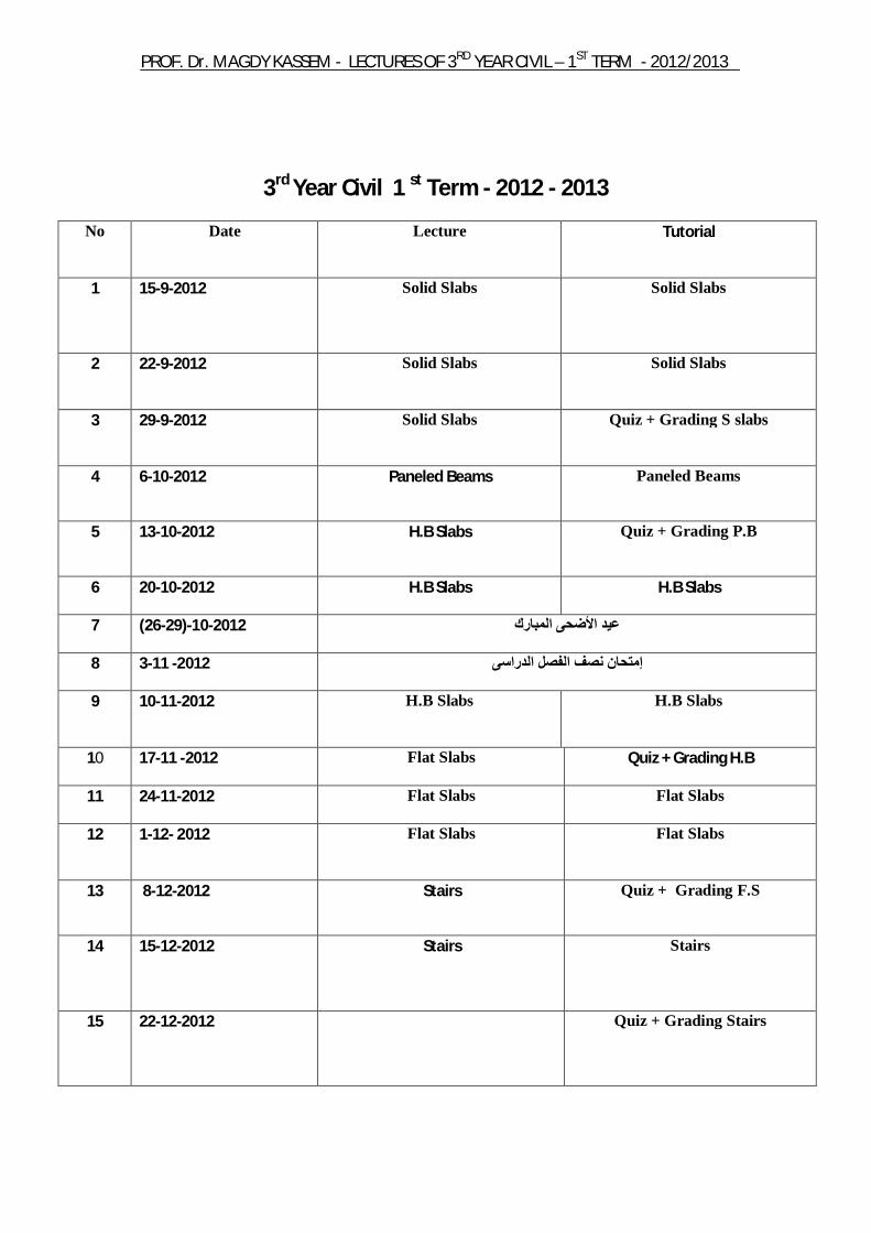
3rd Year Civil 1 st Term - 2012 - 2013
Tutorial Lecture Date No
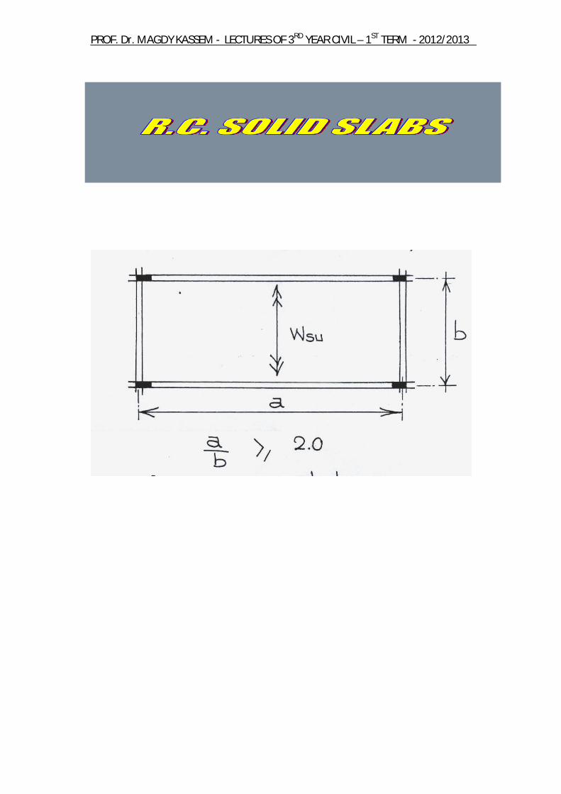
Solid Slabs
Solid Slabs 15-9-2012
1
Solid Slabs
Solid Slabs 22-9-2012 2
Quiz + Grading S slabs
Solid Slabs 29-9-2012 3
Paneled Beams
Paneled Beams 6-10-2012 4
Quiz + Grading P.B
H.B Slabs 13-10-2012 5
H.B Slabs H.B Slabs 20-10-2012 6
7 )2012-10-(29-26 عید األضحى المبارك
8 2012- 11-3 ىإمتحان نصف الفصل الدراس
H.B Slabs
H.B Slabs 10-11-2012 9
Quiz + Grading H.B Flat Slabs 17-11 -2012 10
Flat Slabs
Flat Slabs
24-11-2012 11
Flat Slabs
Flat Slabs
1-12- 2012 12
Quiz + Grading F.S
Stairs 8-12-2012 13
Stairs Stairs 15-12-2012
14
Quiz + Grading Stairs 22-12-2012
15
2012/2013 -TERM ST1 –YEAR CIVIL RDLECTURES OF 3 - AGDY KASSEMDr. MPROF.
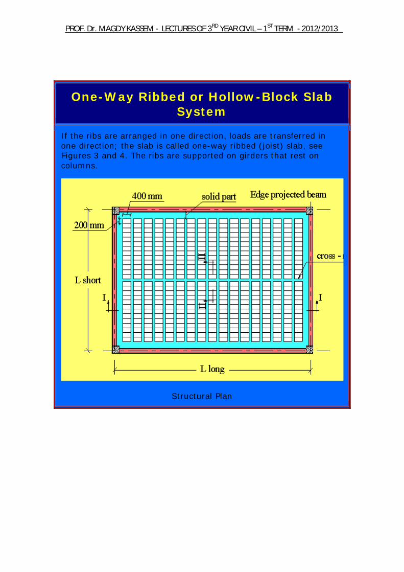
One-Way Ribbed or Hollow-Block Slab System
If the ribs are arranged in one direction, loads are transferred in one direction; the slab is called one-way ribbed (joist) slab, see Figures 3 and 4. The ribs are supported on girders that rest on columns.
Structural Plan

2012/2013 -TERM ST1 –YEAR CIVIL RDLECTURES OF 3 - AGDY KASSEMDr. MPROF.
Figure 3: One-Way hollow-block slab system
Figure 4: Isometric of one-way hollow-block slab system
2012/2013 -TERM ST1 –YEAR CIVIL RDLECTURES OF 3 - AGDY KASSEMDr. MPROF.
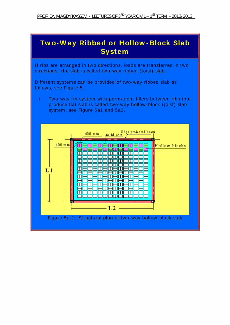
Two-Way Ribbed or Hollow-Block Slab System
If ribs are arranged in two directions, loads are transferred in two directions; the slab is called two-way ribbed (joist) slab. Different systems can be provided of two-way ribbed slab as follows, see Figure 5.
i. Two-way rib system with permanent fillers between ribs that produce flat slab is called two-way hollow-block (joist) slab system, see Figure 5a1 and 5a2.
Figure 5a-1: Structural plan of two-way hollow-block slab
2012/2013 -TERM ST1 –YEAR CIVIL RDLECTURES OF 3 - AGDY KASSEMDr. MPROF.
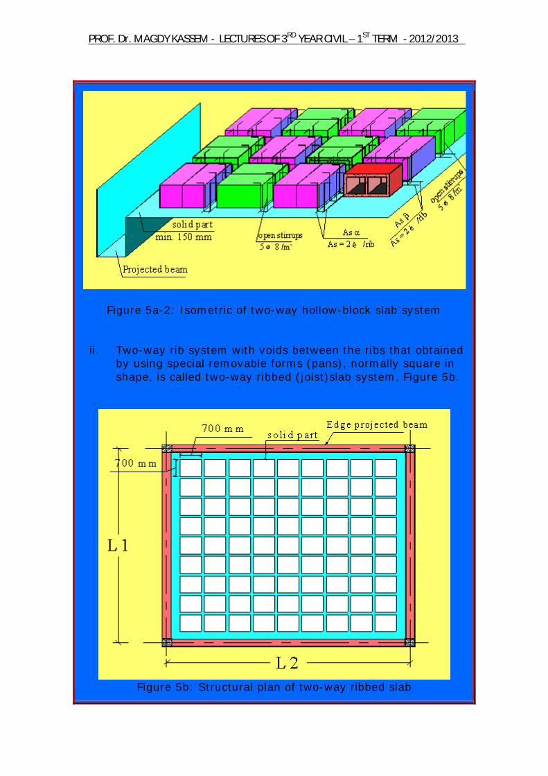
Figure 5a-2: Isometric of two-way hollow-block slab system
ii. Two-way rib system with voids between the ribs that obtained by using special removable forms (pans), normally square in shape, is called two-way ribbed (joist)slab system, Figure 5b.
Figure 5b: Structural plan of two-way ribbed slab
2012/2013 -TERM ST1 –YEAR CIVIL RDLECTURES OF 3 - AGDY KASSEMDr. MPROF.
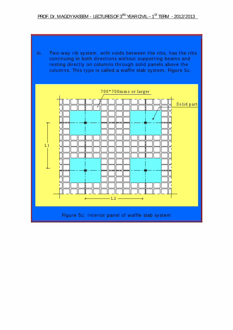
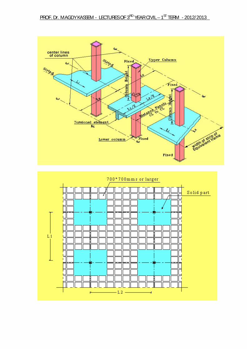
iii. Two-way rib system, with voids between the ribs, has the ribs continuing in both directions without supporting beams and resting directly on columns through solid panels above the columns. This type is called a waffle slab system, Figure 5c.
Figure 5c: Interior panel of waffle slab system
2012/2013 -TERM ST1 –YEAR CIVIL RDLECTURES OF 3 - AGDY KASSEMDr. MPROF.
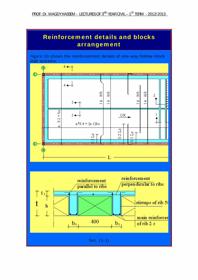
Reinforcement details and blocks arrangement
Figure 10 shows the reinforcement details of one-way hollow-block slab systems.
Sec. (1-1)
2012/2013 -TERM ST1 –YEAR CIVIL RDLECTURES OF 3 - AGDY KASSEMDr. MPROF.
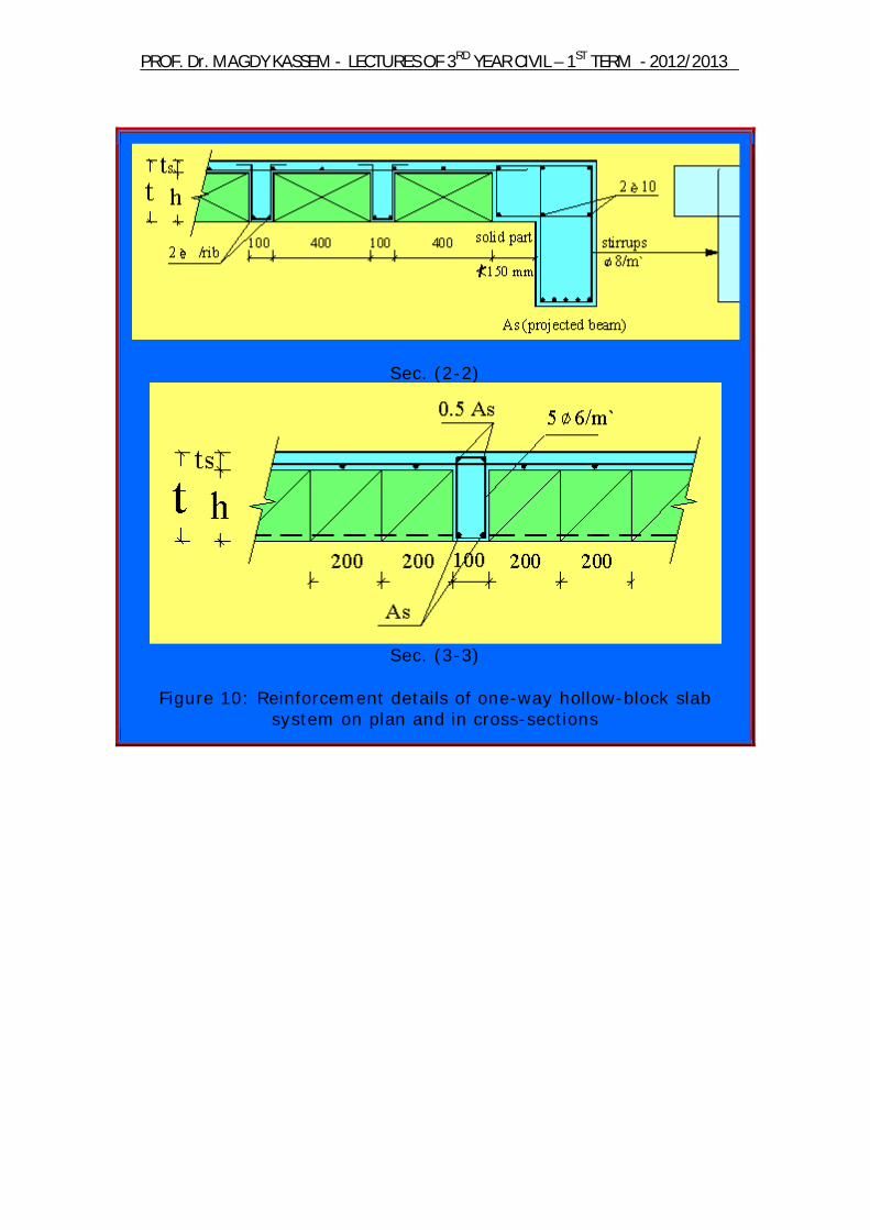
Sec. (2-2)
Sec. (3-3)
Figure 10: Reinforcement details of one-way hollow-block slab
system on plan and in cross-sections
2012/2013 -TERM ST1 –YEAR CIVIL RDLECTURES OF 3 - AGDY KASSEMDr. MPROF.
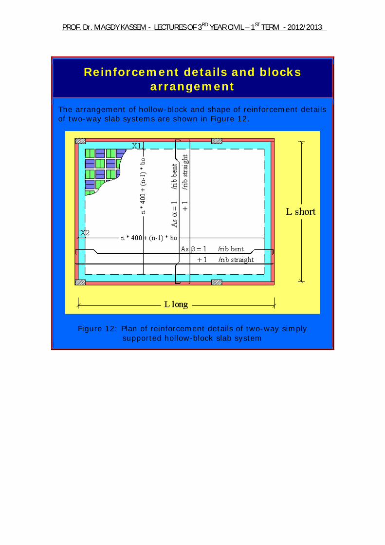
Reinforcement details and blocks arrangement
The arrangement of hollow-block and shape of reinforcement details of two-way slab systems are shown in Figure 12.
Figure 12: Plan of reinforcement details of two-way simply supported hollow-block slab system
2012/2013 -TERM ST1 –YEAR CIVIL RDLECTURES OF 3 - AGDY KASSEMDr. MPROF.
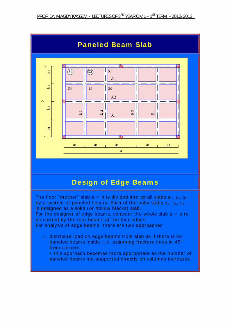
Paneled Beam Slab
Design of Edge Beams
The floor "mother" slab a × b is divided into small slabs s1, s2, s3 by a system of paneled beams. Each of the baby slabs s1, s2, s3 ….. is designed as a solid (or hollow blacks) slab. For the designer of edge beams, consider the whole slab a × b to be carried by the four beams at the four edges: For analysis of edge beams, there are two approaches:
1. distribute load on edge beams from slab as if there is no paneled beams inside, i.e. assuming fracture lines at 45o from corners. • this approach becomes more appropriate as the number of paneled beams not supported directly on columns increases.
2012/2013 -TERM ST1 –YEAR CIVIL RDLECTURES OF 3 - AGDY KASSEMDr. MPROF.
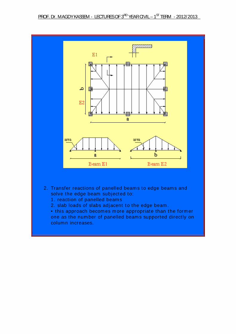
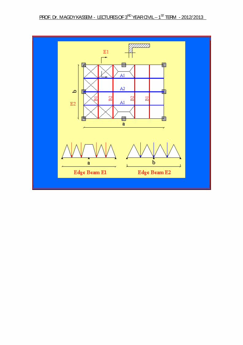
2. Transfer reactions of panelled beams to edge beams and solve the edge beam subjected to: 1. reaction of panelled beams 2. slab loads of slabs adjacent to the edge beam. • this approach becomes more appropriate than the former one as the number of panelled beams supported directly on column increases.
2012/2013 -TERM ST1 –YEAR CIVIL RDLECTURES OF 3 - AGDY KASSEMDr. MPROF.
2012/2013 -TERM ST1 –YEAR CIVIL RDLECTURES OF 3 - AGDY KASSEMDr. MPROF.
Flat Slabs
Introduction
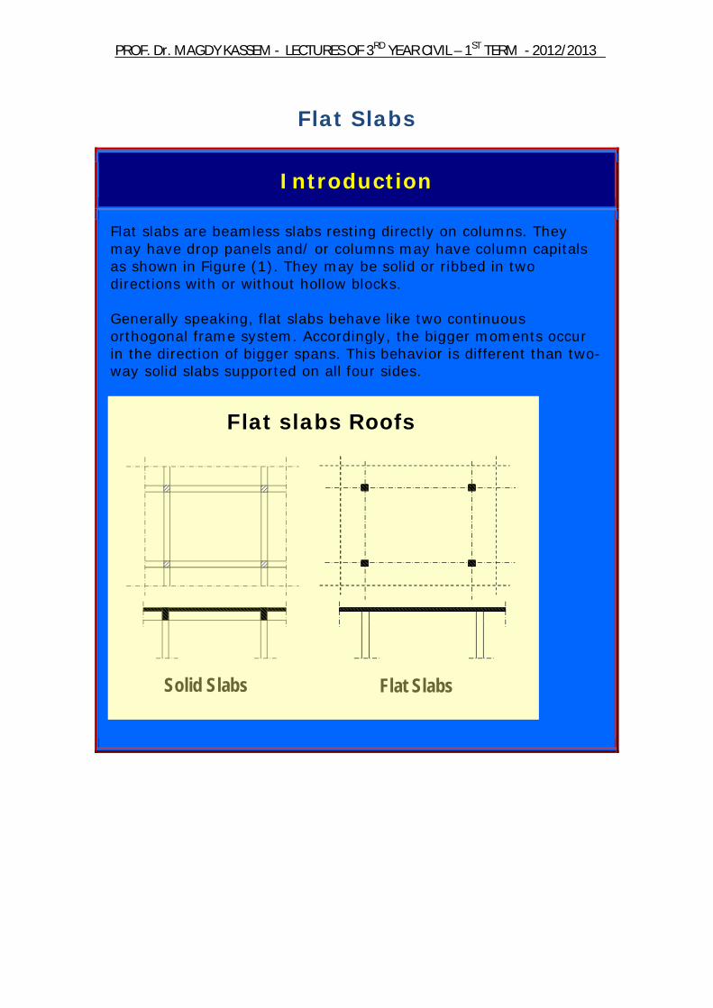
Flat slabs are beamless slabs resting directly on columns. They may have drop panels and/ or columns may have column capitals as shown in Figure (1). They may be solid or ribbed in two directions with or without hollow blocks. Generally speaking, flat slabs behave like two continuous orthogonal frame system. Accordingly, the bigger moments occur in the direction of bigger spans. This behavior is different than two-way solid slabs supported on all four sides.
Flat slabs Roofs
Solid Slabs Flat Slabs
2012/2013 -TERM ST1 –YEAR CIVIL RDLECTURES OF 3 - AGDY KASSEMDr. MPROF.
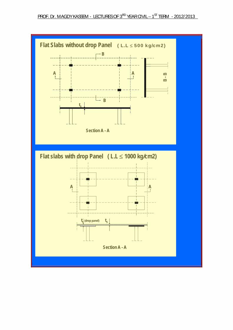
A A
B
B
Section A - A
Flat Slabs without drop Panel ( L.L 500 kg/cm2)
ts
Section A - A
Flat slabs with drop Panel ( L.L 1000 kg/cm2)
A A
tsts (drop panel)
2012/2013 -TERM ST1 –YEAR CIVIL RDLECTURES OF 3 - AGDY KASSEMDr. MPROF.
2012/2013 -TERM ST1 –YEAR CIVIL RDLECTURES OF 3 - AGDY KASSEMDr. MPROF.
Flat Slabs
2012/2013 -TERM ST1 –YEAR CIVIL RDLECTURES OF 3 - AGDY KASSEMDr. MPROF.

2012/2013 -TERM ST1 –YEAR CIVIL RDLECTURES OF 3 - AGDY KASSEMDr. MPROF.
o Stairs Slab and Beam Type Slab Type Cantilever Type
Cantilever Type
2012/2013 -TERM ST1 –YEAR CIVIL RDLECTURES OF 3 - AGDY KASSEMDr. MPROF.
Solid Slabs One Way Slabs
Effective Span Loads Minimum Thickness Bending Moments Reinforcement Supports
Two Way Slabs General Effective Spans Minimum Thickness Simplified Method for Calculating
B.M. in Two Way Slabs Reinforcement Calculations
Practical Cases Concluding Remarks
2012/2013 -TERM ST1 –YEAR CIVIL RDLECTURES OF 3 - AGDY KASSEMDr. MPROF.
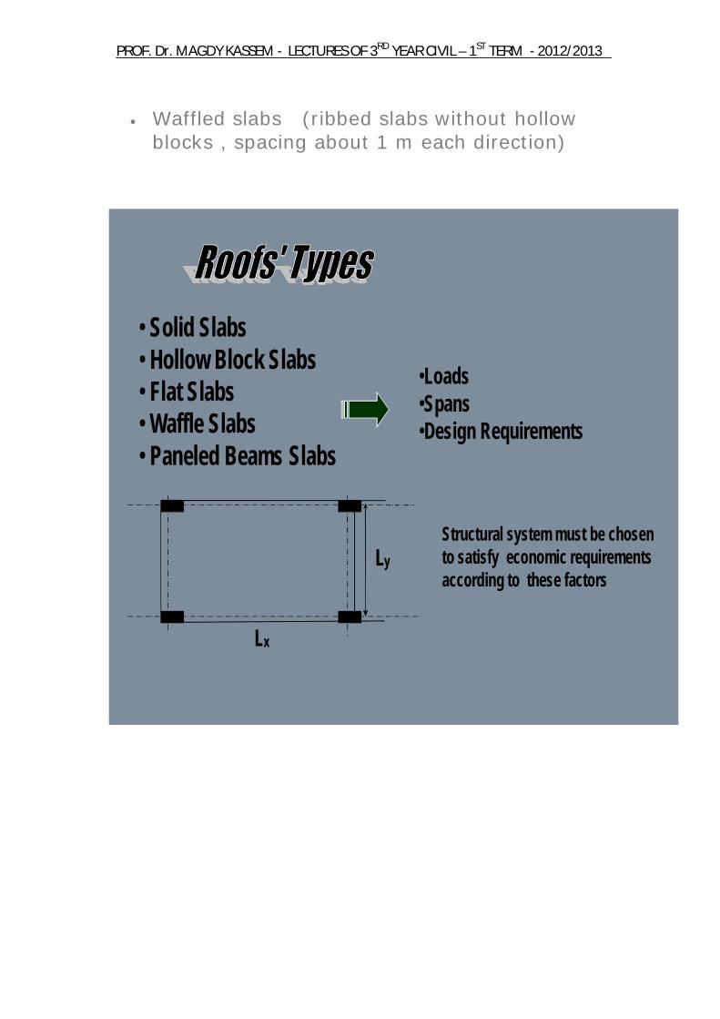
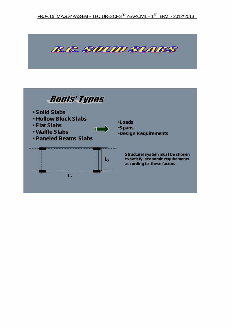
Waffled slabs (ribbed slabs without hollow blocks , spacing about 1 m each direction)
• Solid Slabs• Hollow Block Slabs• Flat Slabs• Waffle Slabs• Paneled Beams Slabs
•Loads•Spans •Design Requirements
Ly
Lx
Structural system must be chosen to satisfy economic requirements according to these factors
2012/2013 -TERM ST1 –YEAR CIVIL RDLECTURES OF 3 - AGDY KASSEMDr. MPROF.
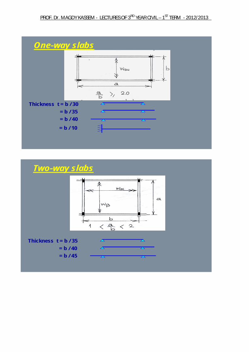
One-way slabs
Thickness t = b / 30= b / 35= b / 40= b / 10
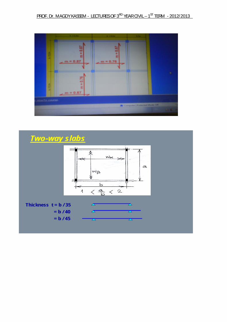
Two-way slabs
Thickness t = b / 35= b / 40= b / 45
2012/2013 -TERM ST1 –YEAR CIVIL RDLECTURES OF 3 - AGDY KASSEMDr. MPROF.
2012/2013 -TERM ST1 –YEAR CIVIL RDLECTURES OF 3 - AGDY KASSEMDr. MPROF.
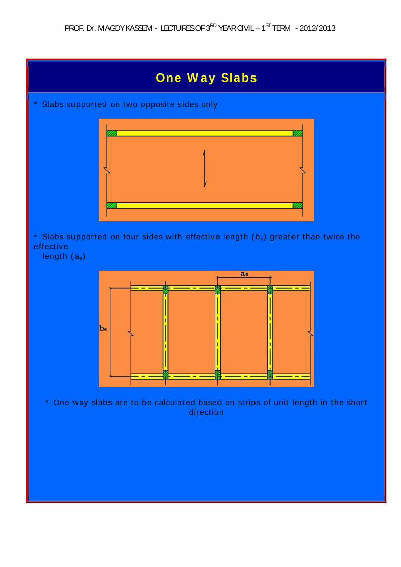
One Way Slabs
* Slabs supported on two opposite sides only
* Slabs supported on four sides with effective length (be) greater than twice the effective length (ae)
* One way slabs are to be calculated based on strips of unit length in the short direction

2012/2013 -TERM ST1 –YEAR CIVIL RDLECTURES OF 3 - AGDY KASSEMDr. MPROF.
Effective Span
i) Le for simple or continues slab is the larger of :
(Lc + ts) or 1.05 Lc or Le < L
ii) Le for cantilever slabs is the smaller of :
L or Lc + ts
iii) Continuous or simply supported slabs supported on beams with b > 0.2 Lc can be designed as fixed at support, and every span can be calculated separately
2012/2013 -TERM ST1 –YEAR CIVIL RDLECTURES OF 3 - AGDY KASSEMDr. MPROF.
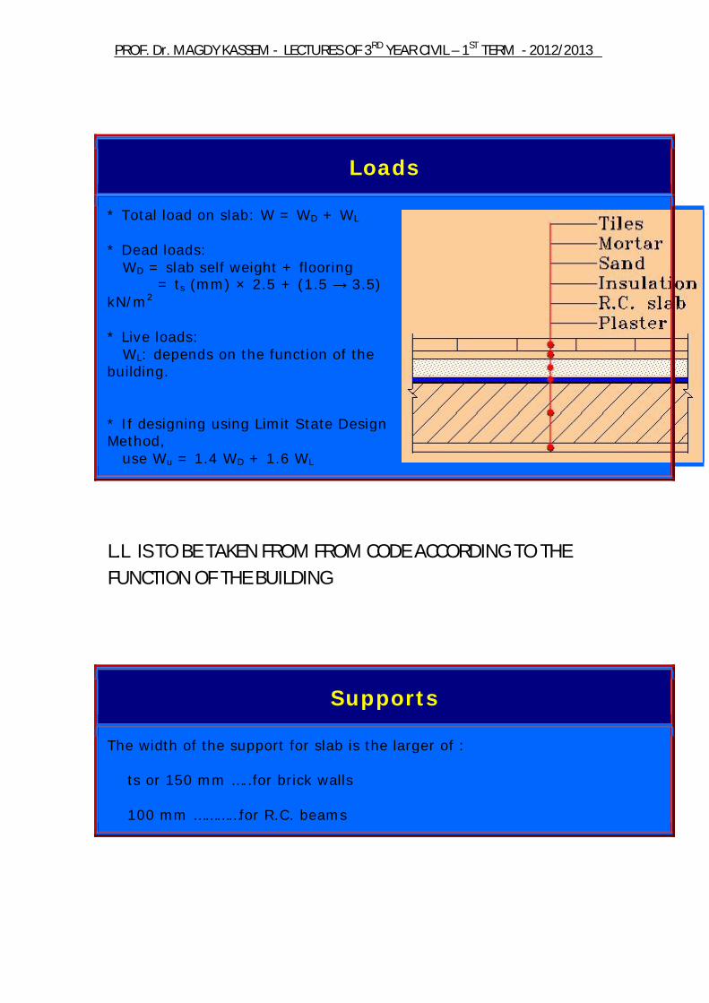
Loads
* Total load on slab: W = WD + WL * Dead loads: WD = slab self weight + flooring = ts (mm) × 2.5 + (1.5 → 3.5) kN/m2 * Live loads: WL: depends on the function of the building. * If designing using Limit State Design Method, use Wu = 1.4 WD + 1.6 WL
L.L IS TO BE TAKEN FROM FROM CODE ACCORDING TO THE FUNCTION OF THE BUILDING
Supports
The width of the support for slab is the larger of : ts or 150 mm …..for brick walls 100 mm …………for R.C. beams

2012/2013 -TERM ST1 –YEAR CIVIL RDLECTURES OF 3 - AGDY KASSEMDr. MPROF.
Minimum Thickness
1. Slab thickness shall not be less than the absolute minimum of: tmin = Le/30 simply supported at both ends tmin = Le/35 continuous at one end tmin = Le/40 continuous at both ends
Where Le is the effective span as defined above 2. For ordinary buildings and cast-in-situ slabs: ts > 80 mm under static loads ts > 120 mm under dynamic loads 3. Smaller thicknesses can be used in pre-cast slabs. 4. Minimum thickness to satisfy the deflection limits in ordinary buildings (i.e. no need to check deflection if the slab thickness is not less than the values indicated) is as follows:
Table (4-10) – ECCS 203-2001
Span / depth ratio; L/d
* Table (4-10) applies only if the following conditions are satisfied: 1. ordinary buildings 2. spans ≤ 10 m 3. uniform, but not heavy, live load, (live load ≤ twice dead load)

2012/2013 -TERM ST1 –YEAR CIVIL RDLECTURES OF 3 - AGDY KASSEMDr. MPROF.
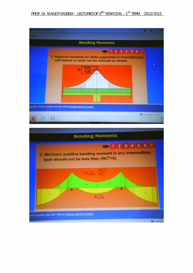
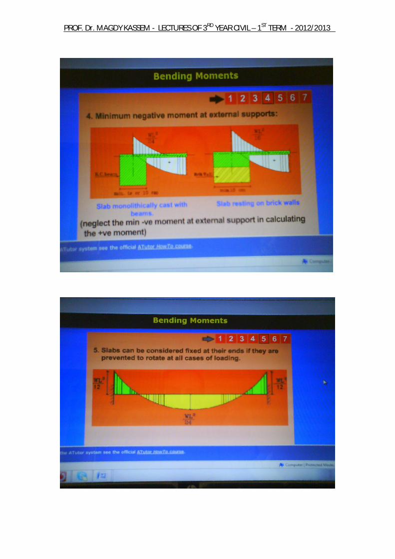
Bending Moments
N.B. * In designing with Ultimate Limit States Design Method: w = wultimate * In designing with Working Stress Design Method: w = wworking
2012/2013 -TERM ST1 –YEAR CIVIL RDLECTURES OF 3 - AGDY KASSEMDr. MPROF.
2012/2013 -TERM ST1 –YEAR CIVIL RDLECTURES OF 3 - AGDY KASSEMDr. MPROF.

2012/2013 -TERM ST1 –YEAR CIVIL RDLECTURES OF 3 - AGDY KASSEMDr. MPROF.
2012/2013 -TERM ST1 –YEAR CIVIL RDLECTURES OF 3 - AGDY KASSEMDr. MPROF.
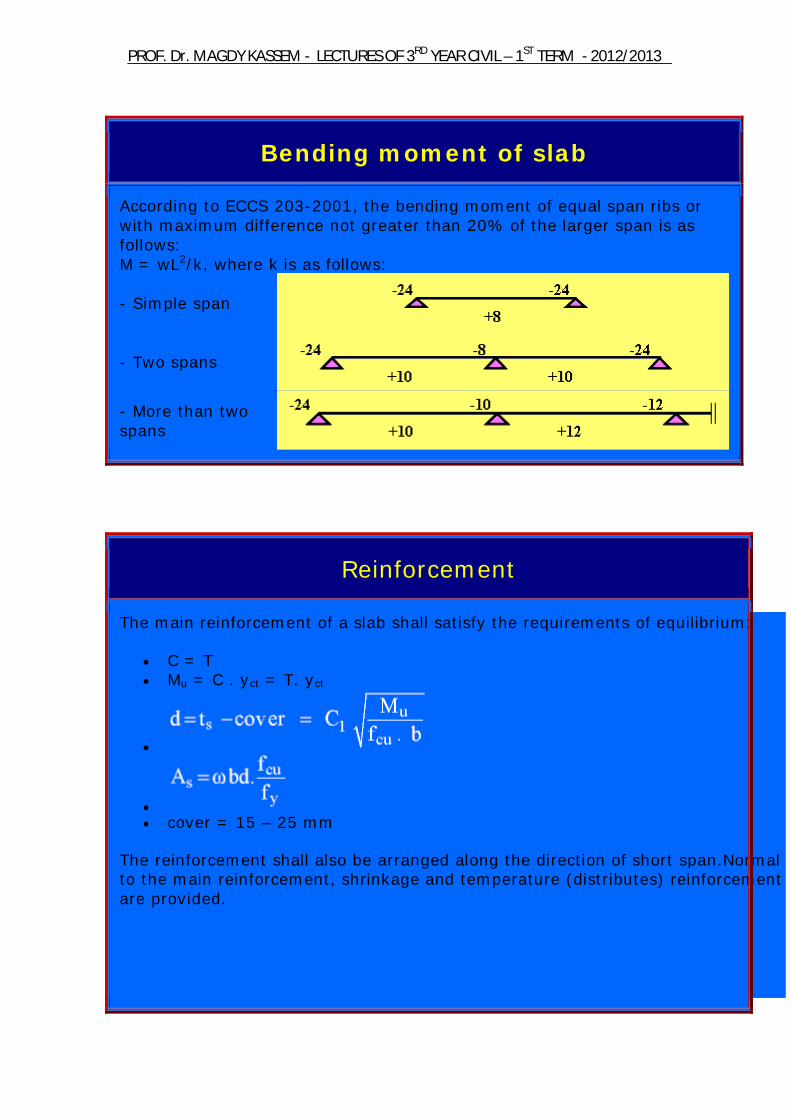
Bending moment of slab
According to ECCS 203-2001, the bending moment of equal span ribs or with maximum difference not greater than 20% of the larger span is as follows: M = wL2/k, where k is as follows:
- Simple span
- Two spans
- More than two spans
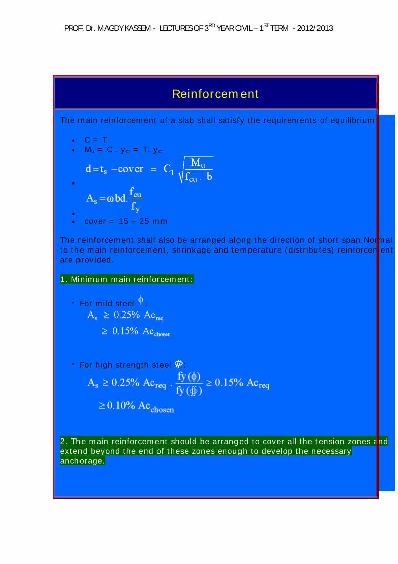
Reinforcement
The main reinforcement of a slab shall satisfy the requirements of equilibrium:
C = T Mu = C . yct = T. yct
cover = 15 – 25 mm
The reinforcement shall also be arranged along the direction of short span.Normal to the main reinforcement, shrinkage and temperature (distributes) reinforcement are provided.
2012/2013 -TERM ST1 –YEAR CIVIL RDLECTURES OF 3 - AGDY KASSEMDr. MPROF.
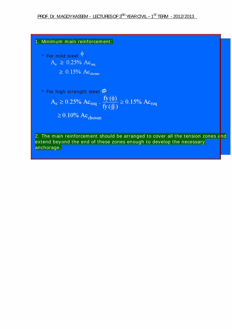
1. Minimum main reinforcement:
* For mild steel :
* For high strength steel :
2. The main reinforcement should be arranged to cover all the tension zones and extend beyond the end of these zones enough to develop the necessary anchorage.
2012/2013 -TERM ST1 –YEAR CIVIL RDLECTURES OF 3 - AGDY KASSEMDr. MPROF.
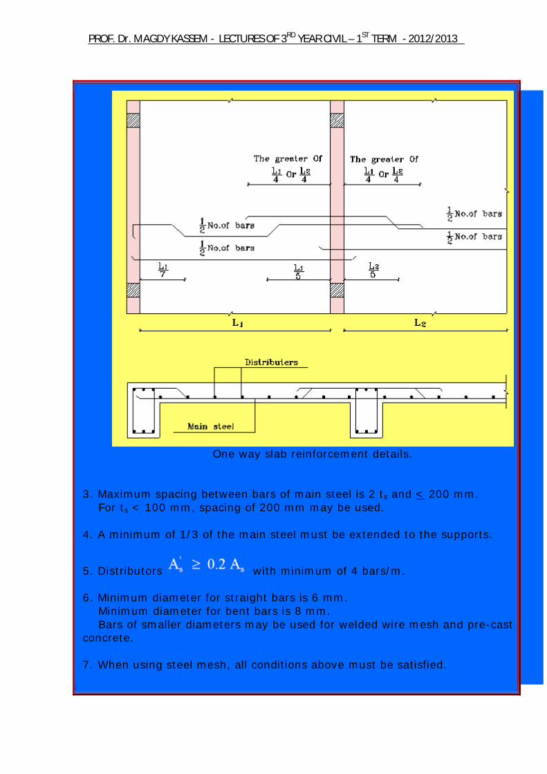
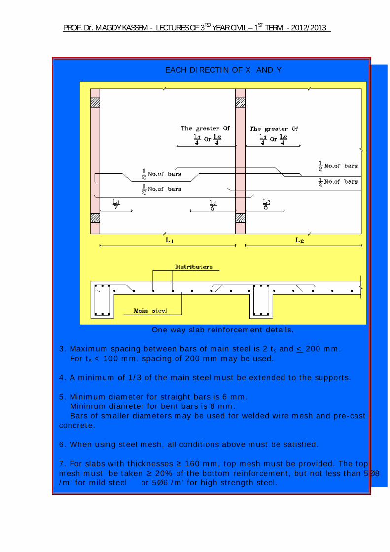
One way slab reinforcement details.
3. Maximum spacing between bars of main steel is 2 ts and < 200 mm. For ts < 100 mm, spacing of 200 mm may be used. 4. A minimum of 1/3 of the main steel must be extended to the supports.
5. Distributors with minimum of 4 bars/m. 6. Minimum diameter for straight bars is 6 mm. Minimum diameter for bent bars is 8 mm. Bars of smaller diameters may be used for welded wire mesh and pre-cast concrete. 7. When using steel mesh, all conditions above must be satisfied.
2012/2013 -TERM ST1 –YEAR CIVIL RDLECTURES OF 3 - AGDY KASSEMDr. MPROF.
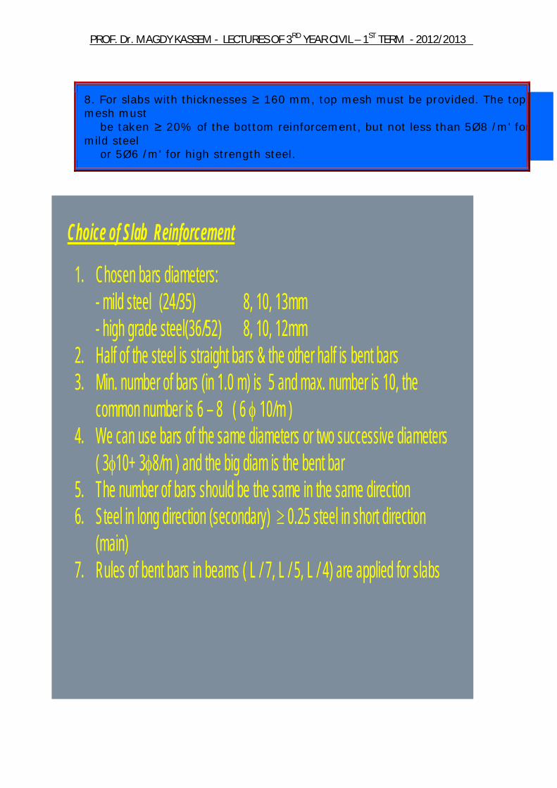
8. For slabs with thicknesses ≥ 160 mm, top mesh must be provided. The top mesh must be taken ≥ 20% of the bottom reinforcement, but not less than 5Ø8 /m' for mild steel or 5Ø6 /m' for high strength steel.
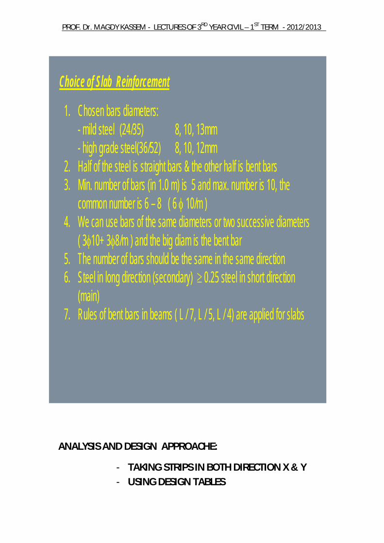
Choice of Slab Reinforcement
1. Chosen bars diameters:- mild steel (24/35) 8, 10, 13mm- high grade steel(36/52) 8, 10, 12mm
2. Half of the steel is straight bars & the other half is bent bars3. Min. number of bars (in 1.0 m) is 5 and max. number is 10, the
common number is 6 – 8 ( 6 10/m )4. We can use bars of the same diameters or two successive diameters
( 310+ 38/m ) and the big diam is the bent bar5. The number of bars should be the same in the same direction6. Steel in long direction (secondary) 0.25 steel in short direction
(main)7. Rules of bent bars in beams ( L / 7, L / 5, L / 4) are applied for slabs
2012/2013 -TERM ST1 –YEAR CIVIL RDLECTURES OF 3 - AGDY KASSEMDr. MPROF.
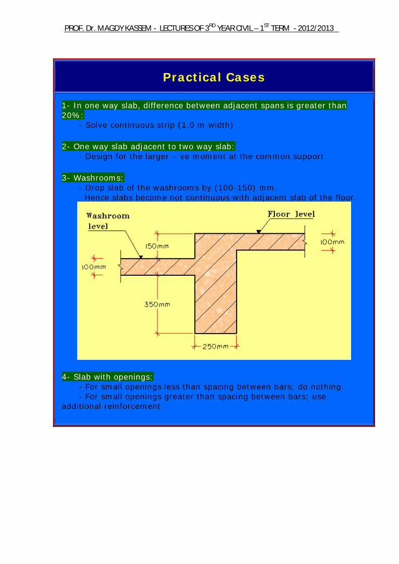
Practical Cases
1- In one way slab, difference between adjacent spans is greater than 20%: - Solve continuous strip (1.0 m width) 2- One way slab adjacent to two way slab: - Design for the larger – ve moment at the common support 3- Washrooms: - Drop slab of the washrooms by (100-150) mm. Hence slabs become not continuous with adjacent slab of the floor.
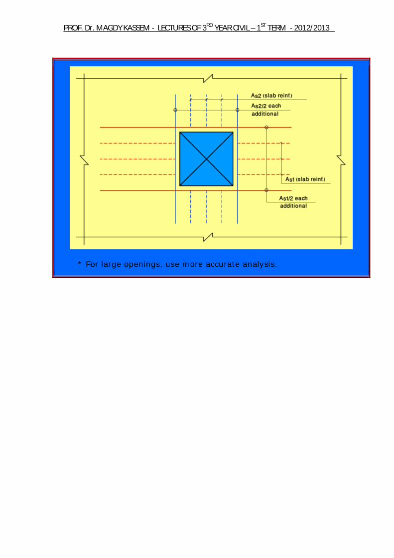
4- Slab with openings: - For small openings less than spacing between bars; do nothing. - For small openings greater than spacing between bars; use additional reinforcement.

2012/2013 -TERM ST1 –YEAR CIVIL RDLECTURES OF 3 - AGDY KASSEMDr. MPROF.
* For large openings, use more accurate analysis.

2012/2013 -TERM ST1 –YEAR CIVIL RDLECTURES OF 3 - AGDY KASSEMDr. MPROF.
Two Way Slabs
Two-way slabs
Thickness t = b / 35= b / 40= b / 45
2012/2013 -TERM ST1 –YEAR CIVIL RDLECTURES OF 3 - AGDY KASSEMDr. MPROF.
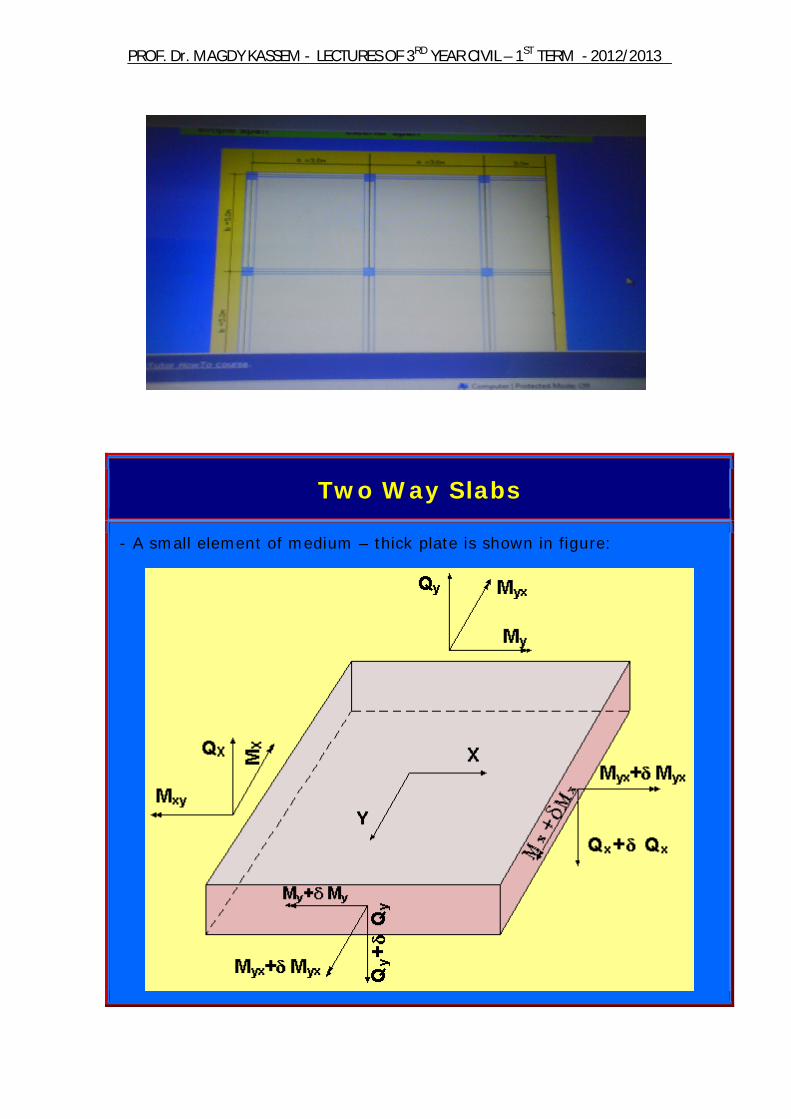
Two Way Slabs
- A small element of medium – thick plate is shown in figure:

2012/2013 -TERM ST1 –YEAR CIVIL RDLECTURES OF 3 - AGDY KASSEMDr. MPROF.
The following equation gives the basic equilibrium requirement for a medium thick plate:
Unlike one way slabs which deform under load into nearly a cylindrical surface, two way slabs bend into a dished surface. This means that at any point, the slab is curved in both directions. The applied distributed load “W” on the element is carried partly by bending as a beam strip in the x-direction producing “Mx”, partly by bending of the strip in the y-direction producing “My”, and the remainder by interaction between the x and y strips, i.e. by torsion producing Mxy .
General
1. Rectangular slabs supported on all four sides can be considered as two way slabs if the rectangularity ratio “r” is smaller than 2, or large than 0.5. 2. Slabs can be solved according to the elastic theories on condition that the reinforcement resisting –ve moments is placed in the right position during casting.. 3. The following method of design is valid only for ordinary buildings with small uniformly distributed live load up to 5 kN/m2.

2012/2013 -TERM ST1 –YEAR CIVIL RDLECTURES OF 3 - AGDY KASSEMDr. MPROF.
Loads
* Total load on slab: W = WD + WL * Dead loads: WD = slab self weight + flooring = ts (mm) × 2.5 + (1.5 → 3.5) kN/m2 * Live loads: WL: depends on the function of the building. * If designing using Limit State Design Method, use Wu = 1.4 WD + 1.6 WL
L.L IS TO BE TAKEN FROM FROM CODE ACCORDING TO THE FUNCTION OF THE BUILDING
Supports
The width of the support for slab is the larger of : ts or 150 mm …..for brick walls 100 mm …………for R.C. beams
Effective Spans
- Refer to one way slabs.

2012/2013 -TERM ST1 –YEAR CIVIL RDLECTURES OF 3 - AGDY KASSEMDr. MPROF.
Minimum Thickness
1. Slab thickness shall not be less than the absolute minimum of: tmin = Le/35 for freely supported slab tmin = Le/40 for slab continuous at one end tmin = Le/45 for continuous or fixed slab
Where Le = the smaller effective span of the slab as indicated in one way slabs.
2012/2013 -TERM ST1 –YEAR CIVIL RDLECTURES OF 3 - AGDY KASSEMDr. MPROF.
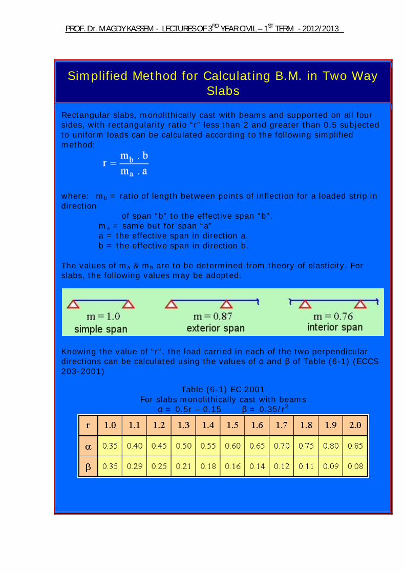
Simplified Method for Calculating B.M. in Two Way Slabs
Rectangular slabs, monolithically cast with beams and supported on all four sides, with rectangularity ratio “r” less than 2 and greater than 0.5 subjected to uniform loads can be calculated according to the following simplified method:
where: mb = ratio of length between points of inflection for a loaded strip in direction of span “b” to the effective span “b”. ma = same but for span “a” a = the effective span in direction a. b = the effective span in direction b. The values of ma & mb are to be determined from theory of elasticity. For slabs, the following values may be adopted.
Knowing the value of “r”, the load carried in each of the two perpendicular directions can be calculated using the values of α and β of Table (6-1) (ECCS 203-2001)
Table (6-1) EC 2001 For slabs monolithically cast with beams
α = 0.5r – 0.15 β = 0.35/r2

2012/2013 -TERM ST1 –YEAR CIVIL RDLECTURES OF 3 - AGDY KASSEMDr. MPROF.
The bending moment in continuous slabs can be calculated as follows:
where: k = 10 for slabs continuous at one end. = 12 for slabs continuous at both ends.
N.B.: negative moment of at exterior support must be considered. For slabs resting on masonry walls, the load distribution factors, α and β are determined according to Table (6-2) ECCS 203-2001.
Table (6-2) (ECCS 203-2001) For slabs resting on masonry walls
* If live load ≥ 500 kg/m2, use Table (6-3) instead of Tables (6-1) and (6-2).
Table (6-3) (ECCS 203-2001) For solid slabs resting with L.L. ≥ 500 kg/m2
2012/2013 -TERM ST1 –YEAR CIVIL RDLECTURES OF 3 - AGDY KASSEMDr. MPROF.
Two-way slabs
Thickness t = b / 35= b / 40= b / 45

2012/2013 -TERM ST1 –YEAR CIVIL RDLECTURES OF 3 - AGDY KASSEMDr. MPROF.
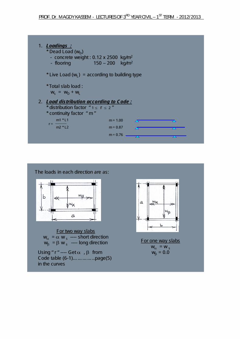
1. Loadings :* Dead Load (wD)
- concrete weight : 0.12 x 2500 kg/m2
- flooring 150 – 200 kg/m2
* Live Load (wL) = according to building type
* Total slab load :ws = wD + wL
2. Load distribution according to Code :* distribution factor “ 1 r 2 ”* continuity factor “ m ”
r =m2 * L2
m1 * L1 m = 1.00
m = 0.87
m = 0.76
The loads in each direction are as:
For two way slabsw = w s ---- short directionw = w s ---- long direction
Using “ r “ ---- Get , from Code table (6-1)…………..page(5) in the curves
For one way slabsw = w sw = 0.0

2012/2013 -TERM ST1 –YEAR CIVIL RDLECTURES OF 3 - AGDY KASSEMDr. MPROF.
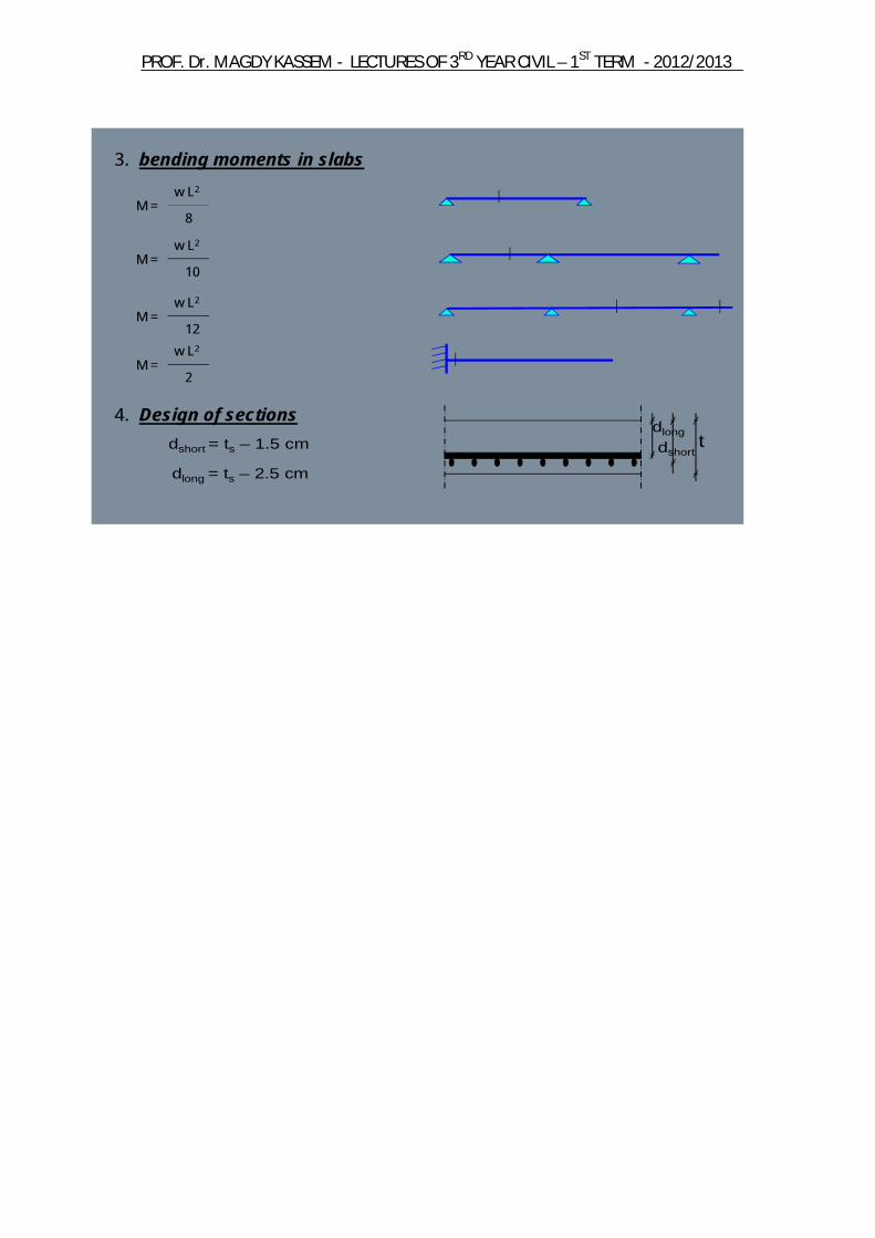
M =8
w L2
3. bending moments in slabs
M =10
w L2
M =12
w L2
4. Design of sections
M =2
w L2
dlong
dshorttdshort = ts – 1.5 cm
dlong = ts – 2.5 cm
2012/2013 -TERM ST1 –YEAR CIVIL RDLECTURES OF 3 - AGDY KASSEMDr. MPROF.
Reinforcement
The main reinforcement of a slab shall satisfy the requirements of equilibrium:
C = T Mu = C . yct = T. yct
cover = 15 – 25 mm
The reinforcement shall also be arranged along the direction of short span.Normal to the main reinforcement, shrinkage and temperature (distributes) reinforcement are provided. 1. Minimum main reinforcement:
* For mild steel :
* For high strength steel :
2. The main reinforcement should be arranged to cover all the tension zones and extend beyond the end of these zones enough to develop the necessary anchorage.
2012/2013 -TERM ST1 –YEAR CIVIL RDLECTURES OF 3 - AGDY KASSEMDr. MPROF.
EACH DIRECTIN OF X AND Y
One way slab reinforcement details.
3. Maximum spacing between bars of main steel is 2 ts and < 200 mm. For ts < 100 mm, spacing of 200 mm may be used. 4. A minimum of 1/3 of the main steel must be extended to the supports. 5. Minimum diameter for straight bars is 6 mm. Minimum diameter for bent bars is 8 mm. Bars of smaller diameters may be used for welded wire mesh and pre-cast concrete. 6. When using steel mesh, all conditions above must be satisfied. 7. For slabs with thicknesses ≥ 160 mm, top mesh must be provided. The top mesh must be taken ≥ 20% of the bottom reinforcement, but not less than 5Ø8 /m' for mild steel or 5Ø6 /m' for high strength steel.

2012/2013 -TERM ST1 –YEAR CIVIL RDLECTURES OF 3 - AGDY KASSEMDr. MPROF.
Reinforcement
1. Maximum spacing of main reinforcement in the middle zone of the span is 2ts but not more than 200 mm. However, For ts < 100 mm , 5 bars/m may be used. 2. Reinforcement in the secondary direction should not be less than 0.25 of the main reinforcement with minimum of 5 bars/m'. 3. Positive reinforcement adjacent and parallel to a continuous edge may be reduced by 25% for a width of not more than ¼ the shorter span of the panel. 4. For other details, refer to one way slabs.
2012/2013 -TERM ST1 –YEAR CIVIL RDLECTURES OF 3 - AGDY KASSEMDr. MPROF.
Choice of Slab Reinforcement
1. Chosen bars diameters:- mild steel (24/35) 8, 10, 13mm- high grade steel(36/52) 8, 10, 12mm
2. Half of the steel is straight bars & the other half is bent bars3. Min. number of bars (in 1.0 m) is 5 and max. number is 10, the
common number is 6 – 8 ( 6 10/m )4. We can use bars of the same diameters or two successive diameters
( 310+ 38/m ) and the big diam is the bent bar5. The number of bars should be the same in the same direction6. Steel in long direction (secondary) 0.25 steel in short direction
(main)7. Rules of bent bars in beams ( L / 7, L / 5, L / 4) are applied for slabs
ANALYSIS AND DESIGN APPROACHE:
- TAKING STRIPS IN BOTH DIRECTION X & Y - USING DESIGN TABLES
2012/2013 -TERM ST1 –YEAR CIVIL RDLECTURES OF 3 - AGDY KASSEMDr. MPROF.
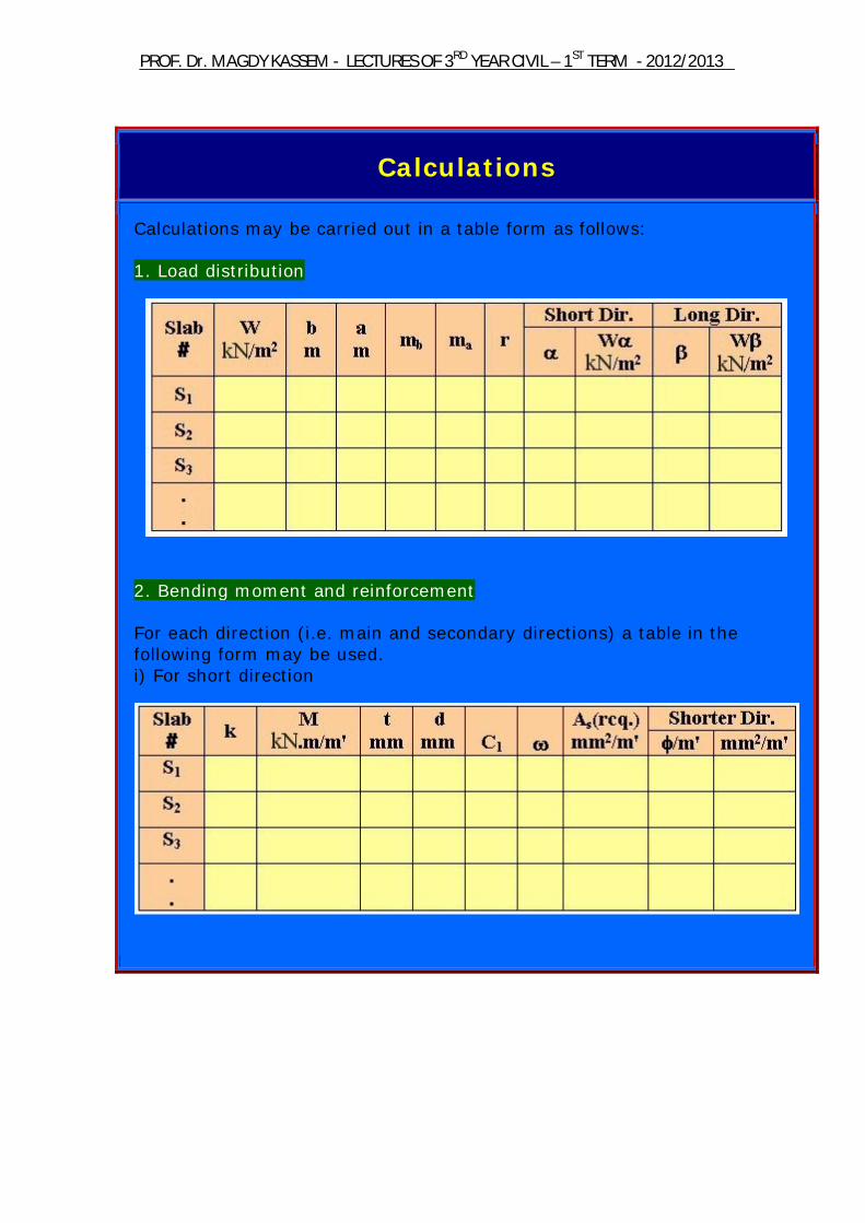
Calculations
Calculations may be carried out in a table form as follows: 1. Load distribution
2. Bending moment and reinforcement For each direction (i.e. main and secondary directions) a table in the following form may be used. i) For short direction
2012/2013 -TERM ST1 –YEAR CIVIL RDLECTURES OF 3 - AGDY KASSEMDr. MPROF.
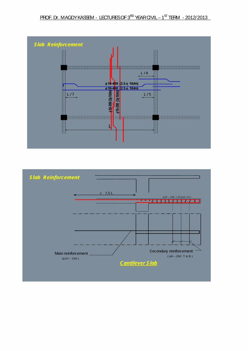
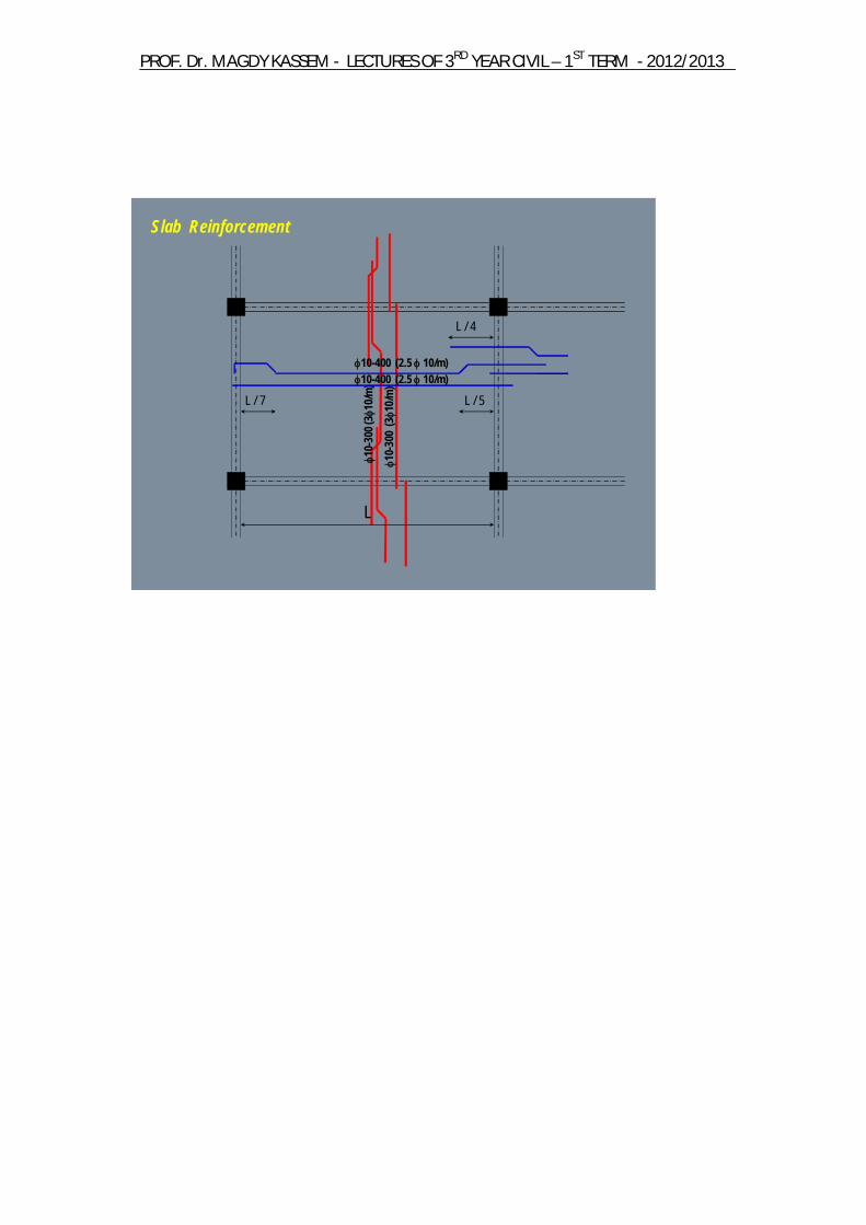
10-3
00 (31
0/m)
10-3
00 (3
10/m
)
10-400 (2.5 10/m)10-400 (2.5 10/m)
Slab Reinforcement
L / 7 L / 5
L / 4
L
1.5 L
•10 – 100 ( 10 10 / m )
• • • • •• • •• • • • • •• • •• • •• • •• • • •
( 8 – 200 T & B )
Secondary reinforcementMain reinforcement(10 – 100 )
Slab Reinforcement
Cantilever Slab

2012/2013 -TERM ST1 –YEAR CIVIL RDLECTURES OF 3 - AGDY KASSEMDr. MPROF.
Practical Cases
1- In one way slab, difference between adjacent spans is greater than 20%: - Solve continuous strip (1.0 m width) 2- One way slab adjacent to two way slab: - Design for the larger – ve moment at the common support 3- Washrooms: - Drop slab of the washrooms by (100-150) mm. Hence slabs become not continuous with adjacent slab of the floor.
4- Slab with openings: - For small openings less than spacing between bars; do nothing. - For small openings greater than spacing between bars; use additional reinforcement.
2012/2013 -TERM ST1 –YEAR CIVIL RDLECTURES OF 3 - AGDY KASSEMDr. MPROF.
* For large openings, use more accurate analysis.
2012/2013 -TERM ST1 –YEAR CIVIL RDLECTURES OF 3 - AGDY KASSEMDr. MPROF.
• Solid Slabs• Hollow Block Slabs• Flat Slabs• Waffle Slabs• Paneled Beams Slabs
•Loads•Spans •Design Requirements
Ly
Lx
Structural system must be chosen to satisfy economic requirements according to these factors

2012/2013 -TERM ST1 –YEAR CIVIL RDLECTURES OF 3 - AGDY KASSEMDr. MPROF.
One-way slabs
Thickness t = b / 30= b / 35= b / 40= b / 10
Two-way slabs
Thickness t = b / 35= b / 40= b / 45
2012/2013 -TERM ST1 –YEAR CIVIL RDLECTURES OF 3 - AGDY KASSEMDr. MPROF.
1. Loadings :* Dead Load (wD)
- concrete weight : 0.12 x 2500 kg/m2
- flooring 150 – 200 kg/m2
* Live Load (wL) = according to building type
* Total slab load :ws = wD + wL
2. Load distribution according to Code :* distribution factor “ 1 r 2 ”* continuity factor “ m ”
r =m2 * L2
m1 * L1 m = 1.00
m = 0.87
m = 0.76
The loads in each direction are as:
For two way slabsw = w s ---- short directionw = w s ---- long direction
Using “ r “ ---- Get , from Code table (6-1)…………..page(5) in the curves
For one way slabsw = w sw = 0.0
2012/2013 -TERM ST1 –YEAR CIVIL RDLECTURES OF 3 - AGDY KASSEMDr. MPROF.
M =8
w L2
3. bending moments in slabs
M =10
w L2
M =12
w L2
4. Design of sections
M =2
w L2
dlong
dshorttdshort = ts – 1.5 cm
dlong = ts – 2.5 cm
2012/2013 -TERM ST1 –YEAR CIVIL RDLECTURES OF 3 - AGDY KASSEMDr. MPROF.
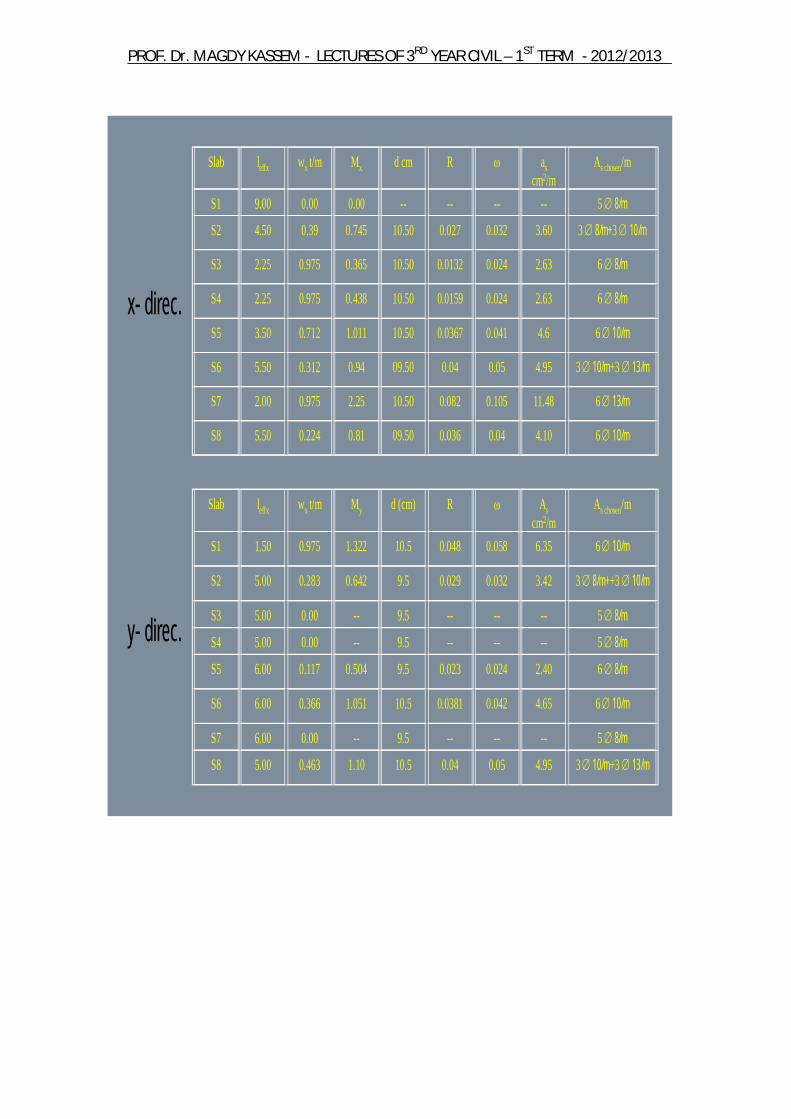
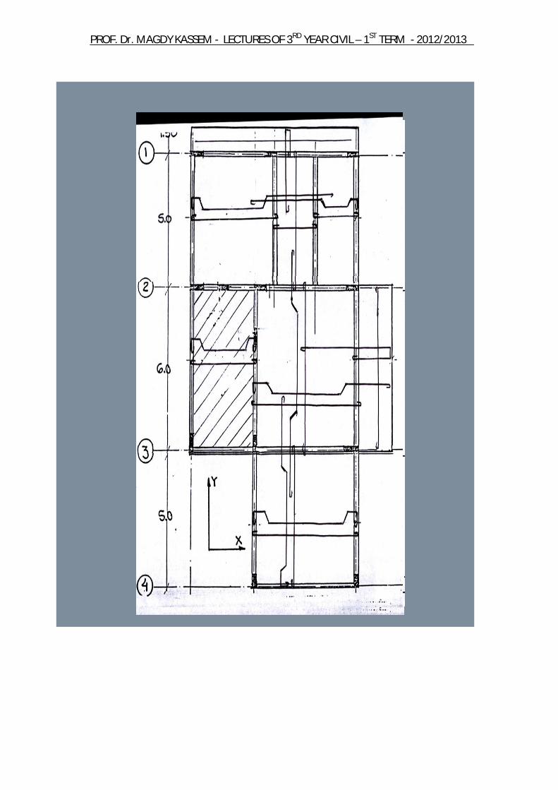
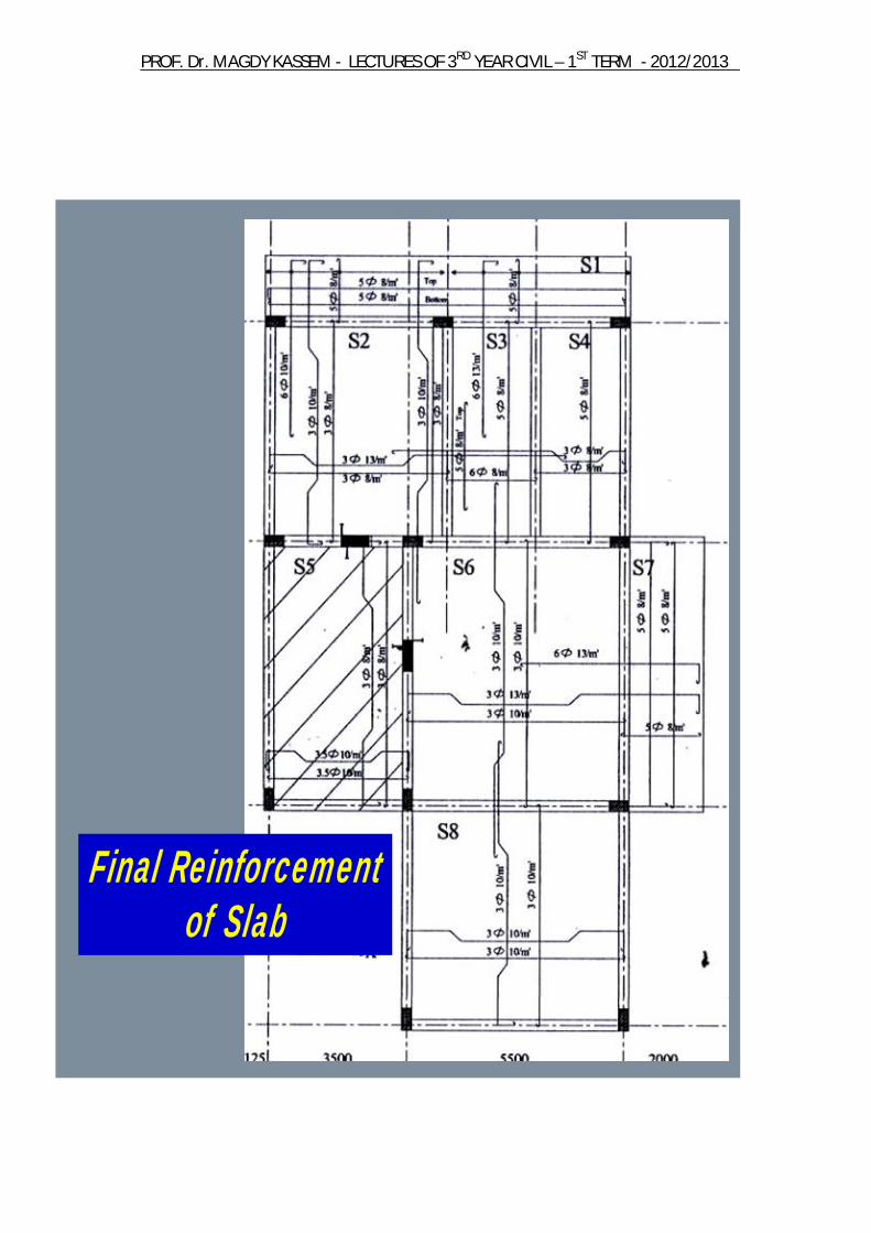
Slab leffx wx t/m Mx d cm R ascm2/m
As chosen/m
S1 9.00 0.00 0.00 -- -- -- -- 5 8/mS2 4.50 0.39 0.745 10.50 0.027 0.032 3.60 3 8/m+3 10/m
S3 2.25 0.975 0.365 10.50 0.0132 0.024 2.63 6 8/m
S4 2.25 0.975 0.438 10.50 0.0159 0.024 2.63 6 8/m
S5 3.50 0.712 1.011 10.50 0.0367 0.041 4.6 6 10/m
S6 5.50 0.312 0.94 09.50 0.04 0.05 4.95 3 10/m+3 13/m
S7 2.00 0.975 2.25 10.50 0.082 0.105 11.48 6 13/m
S8 5.50 0.224 0.81 09.50 0.036 0.04 4.10 6 10/m
Slab leffx wx t/m My d (cm) R Ascm2/m
As chosen/m
S1 1.50 0.975 1.322 10.5 0.048 0.058 6.35 6 10/m
S2 5.00 0.283 0.642 9.5 0.029 0.032 3.42 3 8/m++3 10/m
S3 5.00 0.00 -- 9.5 -- -- -- 5 8/mS4 5.00 0.00 -- 9.5 -- -- -- 5 8/mS5 6.00 0.117 0.504 9.5 0.023 0.024 2.40 6 8/m
S6 6.00 0.366 1.051 10.5 0.0381 0.042 4.65 6 10/m
S7 6.00 0.00 -- 9.5 -- -- -- 5 8/mS8 5.00 0.463 1.10 10.5 0.04 0.05 4.95 3 10/m+3 13/m
x- direc.
y- direc.

2012/2013 -TERM ST1 –YEAR CIVIL RDLECTURES OF 3 - AGDY KASSEMDr. MPROF.
Choice of Slab Reinforcement
1. Chosen bars diameters:- mild steel (24/35) 8, 10, 13mm- high grade steel(36/52) 8, 10, 12mm
2. Half of the steel is straight bars & the other half is bent bars3. Min. number of bars (in 1.0 m) is 5 and max. number is 10, the
common number is 6 – 8 ( 6 10/m )4. We can use bars of the same diameters or two successive diameters
( 310+ 38/m ) and the big diam is the bent bar5. The number of bars should be the same in the same direction6. Steel in long direction (secondary) 0.25 steel in short direction
(main)7. Rules of bent bars in beams ( L / 7, L / 5, L / 4) are applied for slabs
2012/2013 -TERM ST1 –YEAR CIVIL RDLECTURES OF 3 - AGDY KASSEMDr. MPROF.
10-
300 (
310
/m)
10-
300
(31
0/m)
10-400 (2.5 10/m)10-400 (2.5 10/m)
Slab Reinforcement
L / 7 L / 5
L / 4
L

2012/2013 -TERM ST1 –YEAR CIVIL RDLECTURES OF 3 - AGDY KASSEMDr. MPROF.
1.5 L
•10 – 100 ( 10 10 / m )
• • • • •• • •• • • • • •• • •• • •• • •• • • •
( 8 – 200 T & B )
Secondary reinforcementMain reinforcement(10 – 100 )
Slab Reinforcement
Cantilever Slab
2012/2013 -TERM ST1 –YEAR CIVIL RDLECTURES OF 3 - AGDY KASSEMDr. MPROF.
2012/2013 -TERM ST1 –YEAR CIVIL RDLECTURES OF 3 - AGDY KASSEMDr. MPROF.
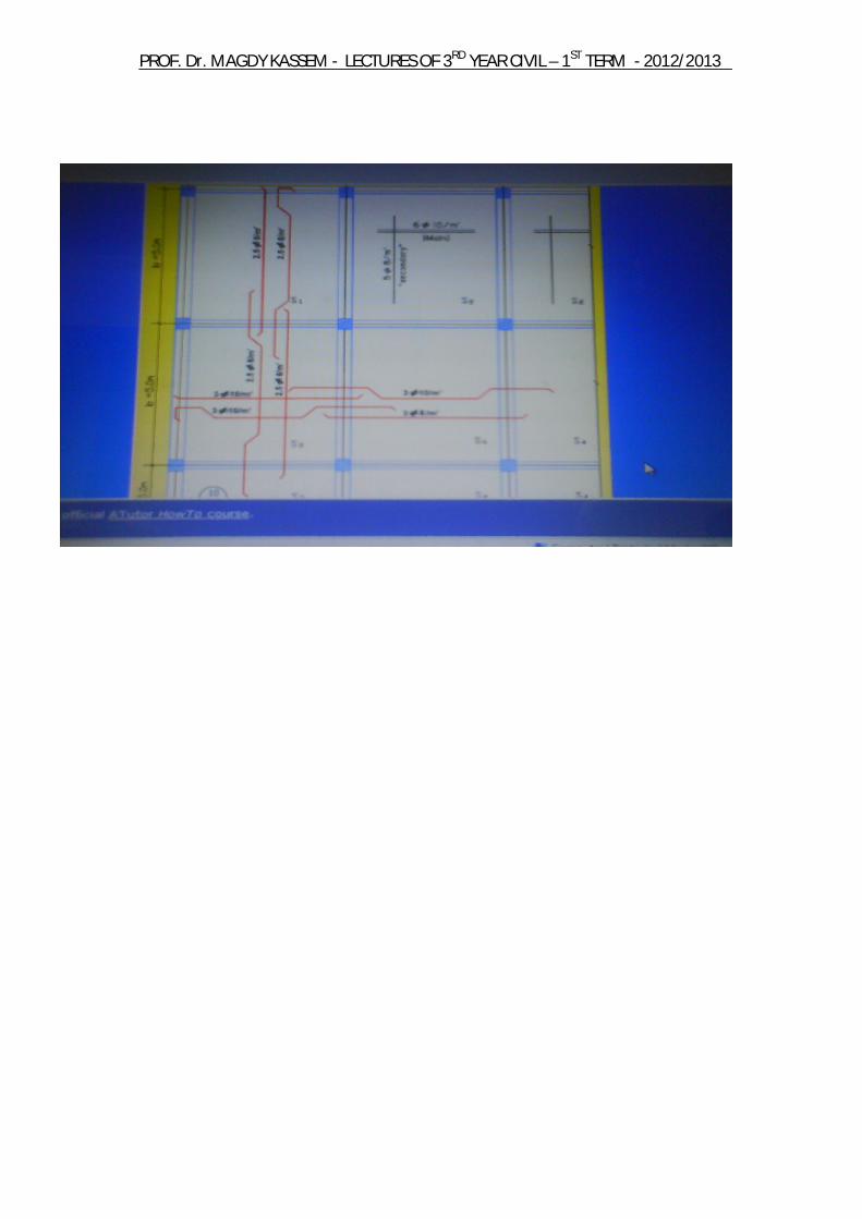
Final Reinforcement of Slab
2012/2013 -TERM ST1 –YEAR CIVIL RDLECTURES OF 3 - AGDY KASSEMDr. MPROF.