rehabilitation of malatya-narli no:7 railroad tunnel …
TRANSCRIPT

REHABILITATION OF MALATYA-NARLI NO:7 RAILROAD TUNNEL
A THESIS SUBMITTED TO THE GRADUATE SCHOOL OF NATURAL AND APPLIED SCIENCES
OF MIDDLE EAST TECHNICAL UNIVERSITY
BY
BARIŞ DİVLELİ
IN PARTIAL FULFILLMENT OF THE REQUIREMENTS FOR THE DEGREE OF MASTER OF SCIENCE
IN MINING ENGINEERING
SEPTEMBER 2004

Approval of the Graduate School of Informatics ________________ (Prof. Dr. Canan Özgen) Director I certify that this thesis satisfies all the requirements as a thesis for the degree of Master of Science/Doctor of Philosophy. ___________________ (Prof. Dr. Ümit Atalay) Head of Department This is to certify that we have read this thesis and that in our opinion it is fully adequate, in scope and quality, as a thesis for the degree of Master of Science/Doctor of Philosophy. _________________ (Prof. Dr. Erdal Ünal) Supervisor Examining Committee Members Prof. Dr. Bahtiyar Ünver _____________________ Prof. Dr. Erdal Ünal _____________________ Assoc. Prof. Dr. Aydın Bilgin _____________________ Assist. Prof. Dr. İhsan Özkan _____________________ M.Sc.Mete Gürler _____________________

iii
I hereby declare that all information in this document has been obtained and presented in accordance with academic rules and ethical conduct. I also declare that, as required by these rules and conduct, I have fully cited and referenced all material and results that are not original to this work. Name, Last name: Barış Divleli Signature :

iv
ABSTRACT
REHABILITATION OF MALATYA-NARLI NO:7
RAILROAD TUNNEL
Divleli, Barış
M.Sc., Mining Engineering Department
Supervisor: Prof. Dr. Erdal Ünal
Semptember 2004, 145 pages
In thesis thesis, studies associated with the rehabilitation of the Malatya-
Narlı No: 7 Railroad Tunnel are presented.
The rehabilitation work includes cleaning of two collapses and stopping of
deformations occurring in the tunnel as well as characterizing the rock-mass by
evaluating the cores obtained from 67 drill holes. Due to two collapses ocurred in
the tunnel a large sinkhole (15x10x20 meters) was developed at the surface and the
tunnel closed to train traffic for 10 months (September, 2002-July, 2003) covering
the initiation of Iraq War.
Originally, the tunnel had been opened into the paleo-landslide material in
1930. The rock-mass surrounding the tunnel consists of limestones, metavolcanics,
and schists.

v
Although the main problem in the tunnel is the reduced tunnel span caused
by displacements triggerred by underground water, poor rock mass and time
dependent deformations, from engineering point of view the other problems can be
sited as collapses occurred in the tunnel, sinkhole devoloped at the surface and
unstable sections existing in the tunnel.
During the field studies, 15 deformation monitoring stations were installed
aimed at determining the deviation from tunnel alignment. In order to provide
stability of the tunnel Self Drilling Anchors (Mai bolts) were installed systematically
around the tunnel. The details of the rock reinforcement design was presented in this
thesis.
Key words: Rehabilitation, collapse, sinkhole, deformation, convergence
measurement, Mai bolts

vi
ÖZ
MALATYA-NARLI HATTI 7 NUMARALI DEMİRYOLU TÜNELİNİN
ISLAH ETME ÇALIŞMALARI
Divleli, Barış
Yüksek Lisans, Maden Mühendisliği Bölümü
Tez Yöneticisi: Prof. Dr. Erdal Ünal
Eylül 2004, 145 sayfa
Bu tezde, Malatya-Narlı hattı 7 numaralı Demiryolu Tünelinin ıslah etme
çalışmaları sunulmuştur.
Islah etme çalışmaları iki göçüğün temizlenmesini, tünelde oluşan
deformasyonların durdurulmasını ve bunlara ilaveten 67 adet sondaj karotlarının
değerlendirilerek kaya kütlesinin tanımlanmasını içermektedir. Tünelde meydana
gelen iki göçükden dolayı yüzeyde 15x10x20 metre ebatlarında çukur oluşmuş ve
tünel ırak savaşının başlangıcı döneminde 10 ay (Eylül, 2002-Temmuz, 2003)
boyunca trafiğe kapatılmıştır.
Başlangıçta, tünel 1930 yılında eski (paleo) heyelan kütlesi içerisinde
açılmıştır. Tüneli çevreleyen kaya kütlesi kireçtaşları, metavolkanitler ve şistlerden
oluşmaktadır.

vii
Tüneldeki esas sorun yeraltı suyunun, zayıf kaya kütlesinin ve zamana
bağlı hareketlerin tetiklediği yer değiştirmeden dolayı oluşan tünel gaberisindeki
azalma olmasına rağmen, mühendislik bakış açısına göre diğer sorunlar göçükler,
yüzeyde oluşmuş çukur, tünel içersinde sağlam olmayan bölgeler olarak
söylenebilir.
Arazi çalışmaları sırasında tünel ekseninde oluşan kaymayı saptamak
amacıyla 15 adet deformasyon gözlem istasyonu oluşturulmuştur. Tünelin
sağlamlığını arttırmak amacıyla Mai bulonları belirli bir düzen içersinde tünelde
uygulanmıştır. Bu konuyla ilgili detaylar bu tez çalışmasında sunulmaktadır.
Anahtar kelimeler: Islah, göçük, çukur, yer değiştirme, kapanma-açılma
(konverjans) ölçümü, Mai bulon

viii
To My Family

ix
ACKNOWLEDGEMENTS
I would like to express my deepest appreciation to Prof. Dr. Erdal Ünal for his kind
supervision, critical review, valuable suggestions, discussion and friendship
throughout this study.
I gratefully acknowledge to the members of examining committee namely, Prof. Dr.
Bahtiyar Ünver, Assoc. Prof. Dr. Aydın Bilgin, Assist. Prof. Dr. İhsan Özkan and
M.Sc. Mete Gürler for their comments and valuable suggestions on this study.
I also wish to express my thanks to Reza R. Osgoui and Alper K. Denli for their
precious suggestions and friendship during my study.
I also wish to express my sincere appreciation to management and all members of
the General Directory of Turkish Railroad especially to the workers of No: 7 Tunnel
in Malatya for their kind assistance in field work.
Finally, but most, I am indepted to all members of my family for their constant
support and encouragement.
x
TABLE OF CONTENTS
PLAGIARISM ......................................................................... iii
ABSTRACT ......................................................................... iv
ÖZ ......................................................................... vi
DEDICATION ......................................................................... viii
ACKNOWLEDGEMENTS ......................................................................... ix
TABLE OF CONTENTS ......................................................................... x
LIST OF TABLES ......................................................................... xiv
LIST OF FIGURES ......................................................................... xv
CHAPTER
1. INTRODUCTION............................................................................ 1
1.1 General Remarks...................................................................... 1
1.2 Statement of the Problem......................................................... 2
1.3 Objectives of the Thesis........................................................... 2
1.4 Thesis Outline.......................................................................... 2
2.LITERATURE SURVEY................................................................. 3
2.1 General..................................................................................... 3
2.2 Factors Affecting the Stability of the Tunnels......................... 3
2.2.1 Underground Water...................................................... 4
2.2.2 Discontinuities.............................................................. 12
2.2.3 Rock Mass.................................................................... 13
2.2.4 Geometry of the Opening............................................. 16
2.2.5 Earthquake.................................................................... 18

xi
2.3 Collapses in Tunnels................................................................... 19
2.3.1 Collapses........................................................................... 19
2.3.2 Sinkhole............................................................................ 27
2.3.3 Subsidence........................................................................ 28
2.3.4 Slope Tunnels................................................................... 30
2.4 Rehabilitation and Improvements of the Tunnels....................... 31
2.4.1 Shotcrete, Bolting and Mesh............................................ 31
2.4.1.1 Examples of Rehabilitated Tunnels....................... 34
2.4.2 Rock Mass Improvement.................................................. 37
2.4.2.1 Soil Improving Intervention.................................. 37
2.4.2.2 Soil Preserving Intervention.................................. 39
2.4.2.3 Examples of Soil and Rock Improvement
Techniques in Tunnels........................................... 40
2.4.3 Regeneration of Lining..................................................... 51
2.4.4 Tunnelling Through Running Ground by
Forepoling Method........................................................... 54
2.5 Stability Measurements of the Tunnels....................................... 56
3. GENERAL INFORMATION ON NO: 7 MALATYA-NARLI
RAILROAD TUNNEL..................................................................... 61
3.1 General........................................................................................ 61
3.2 General Information About No:7 Malatya-Narlı
Railroad Tunnel........................................................................... 61
3.2.1 Location of the Tunnel...................................................... 61
3.2.2 Details Related to Excavation and Dimensions................ 63
3.3 Geology of the Site...................................................................... 64
3.4 Hydrogeology of the Site............................................................ 66
3.5 Stability Problems in the Tunnel 67
4. PROBLEMS RELATED TO THE STABILITY OF THE NO:7
RAILROAD TUNNEL..................................................................... 70
4.1 Problems Related to the Stability of the Tunnel......................... 70
4.2 Excessive Displacements Occurred in the Tunnel...................... 70
4.3 Collapses Occurred During Rehabilitation Work....................... 71

xii
4.3.1 Clearance of the Roof Fall................................................ 74
4.4 Sinkhole Developed at the Surface due to Roof Collapse and Rock Mass Flow into the Tunnel............................................... 81
4.5 Reduced Tunnel Span and Height Preventing Trains to Pass Freelly........................................................................................ 82
4.6 Poor Rock Mass Causing Instability.......................................... 83
4.6.1 Condition of the Tunnel Roof........................................... 83
4.6.2 Condition of the Wall at the Mountain Side..................... 83
4.6.3 Condition of the Wall at the Creek Side........................... 85
4.6.4 Condition of the Tunnel Floor.......................................... 87
4.6.5 Results of Borehole Investigation after Roof Fall............ 87
4.7 Surface and Underground Water Reducing the Tunnel Stability 98
4.7.1 History.............................................................................. 98
4.7.2 Work Performed Inside the Tunnel.................................. 98
4.7.3 Work Performed on the Surface....................................... 100
4.8 Unstable Sections Requiring Urgent Repair............................... 102
5. ROCK REINFORCEMENT IN NO:7 RAILROAD
TUNNEL........................................................................................... 108
5.1 General........................................................................................ 108
5.2 General Remarks about Rock Reinforcement............................. 108
5.3 Reinforced Sections (at the walls of the Tunnel)........................ 109
5.4 Stability of the Floor................................................................... 113
5.5 Self Drilling Anchorage (MAI Bolt)........................................... 117
6. FIELD MEASUREMENTS IN NO:7 MALATYA-NARLI RAILROAD TUNNEL..................................................................... 121
6.1 Introduction................................................................................. 121
6.2 Convergence Measurement......................................................... 121
6.3 Distometer................................................................................... 122
6.4 Locations of Convergence Stations............................................ 124
6.5 Installation of Convergence Stations.......................................... 124
6.6 Frequency of Convergence Measurements................................. 127
6.7 Relations Between “Convergence“ and “Time”......................... 128
7 CONCLUSIONS AND RECOMMENDATIONS............................ 136
7.1 Conclusions................................................................................. 136

xiii
7.2 Recommendations....................................................................... 139
References ........................................................................................................ 140

xiv
LIST OF TABLES
Tables 2.1 Geotechnical Characteristics of the Material............................................. 364.1 The Information Obtained from Cores about the
Stability of the Tunnel............................................................................... 944.2 The Quantity of the Applied Injection in
Different Sections...................................................................................... 1075.1 Technical Specifications of Mai SDA....................................................... 120
5.2 Technical Specifications of Mai Pump...................................................... 120
6.1 Measured Convergence Values................................................................. 131

xv
LIST OF FIGURES
Figures 2.1 (a) Examples of Concrete Tunnels
(b) An Example of an Old Masonry Tunnel............................................. 52.2 Surface Drainage on the Mengen Portal.................................................. 8
2.3 Construction of Impermeable Curtain with Jet Grouting......................... 10
2.4 The Condition of Stresses for Arch Roof and Flat Roof.......................... 172.5 Sidi Mezghiche Tunnel-Cross Sections
(a) Before the Collapse (b) After the Collapse......................................... 202.6 First Collapse in Round 165..................................................................... 21
2.7 Side Wall Failure Showing Configurations of Shear Planes.................... 232.8 (a) View of the Collapse in the Tunnel Face
(b) View of the Sinkhole Form at the Surface.......................................... 242.9 Cross Section of the Collapsed Area and Grouting Pattern
in Kurtkulağı Irrigation Tunnel................................................................ 252.10 Section of the Collapsed Zone in the Kinoura Tunnel............................. 26
2.11 Outline of Countermeasures in Tsukayama Tunnel................................. 35
2.12 Example of Grout Injection Carried Out from the Pilot Tunnel.............. 412.13 Example of Pipe Umbrella Intervention to Improve the
Stability of the Tunnel and the Face of a Road Tunnel............................ 432.14 Some Failed Tunnels in Jiulongkou Mine................................................ 47
2.15 Section of Grouting Holes at the Bottom................................................. 49
2.16 Phased Excavation of the Collapsed Zone............................................... 51
2.17 Measurements in the Reinforcement Zone............................................... 60
3.1 The Location of Gölbaşı........................................................................... 62
3.2 Turkish Railroad Map.............................................................................. 62
3.3 Malatya-Narlı Railroad Map.................................................................... 633.4 Detailed Information Related to No: 7 Tunnel and its
Surroundings............................................................................................ 633.5 The Creek Flowing Parallel to the Tunnel............................................... 653.6 The Location of the Landslides at Right and Left
Banks at Kapıdere.................................................................................... 66
xvi
3.7 Alışlıseki Landslide scarp, Swelling and Settlements at the Mountain Side.................................................................................... 68
3.8 Landslide Materials at the Mountain Side................................................ 68
3.9 Landslide Materials at the Mountain Side................................................ 69
3.10 Landslide Materials at the Mountain Side................................................ 69
4.1 Excessive Displacements Occurred in the Tunnel................................... 71
4.2 Collapse Area and the Void Developed Above the Tunnel....................................................................................................... 72
4.3 Apperance of the Roof-Fall. (a) from Malatya Side (b) from Narlı Side........................................................................................................... 73
4.4 Range of Injection Made Above the Roof of the Collapsed Area................................................................................... 74
4.5 Views of the Support System Used During Clearance of the Collapse......................................................................... 75
4.6 Bench Support Used During Clearance of the Collapsed Material............................................................................. 76
4.7 Installation of Limp (Short) Leg of the Steel-Arch and of the Temporary I-Profiles................................................................................ 76
4.8 Support Used in No:7 Tunnel During Clearance of the Caved Material................................................................................... 78
4.9 Bench Support Used During Clearance of the Collapsed Material............................................................................. 79
4.10 Last Stage of the Clearance of the Collapse............................................. 79
4.11 Sinkhole Developed at the Surface as a Result of the Collapse............... 80
4.12 Estimated Geometry of the Subsidence above the Collapsed Tunnel................................................................................ 81
4.13 Photograph Showing a Reduced Span Close to the Collapsed Area................................................................................... 82
4.14 Cores Taken from the Roof at Station No:4............................................. 84
4.15 Typical Rock Mass at 122.5 m (ST-2) on the Mountain Side of the No:7 Tunnel........................................................................................ 86
4.16 Typical Rock Mass at 122.5 m (ST-2) on the Creek Side of the No:7 Tunnel........................................................................................ 86
4.17 Drilling Stations Before and After Collapse............................................ 89
4.18 Cores Obtained from the Roof in Section 2............................................. 90
4.19 Cores Obtained from the Side Walls in Section 2.................................... 91
4.20 Core Classification and Color Codes....................................................... 92

xvii
4.21 Coreholes Showing Rock Mass Conditions Surrounding Station 2.............................................................................. 93
4.22 Water Drainage Ditches Before and After Inserting the Tunnel Type Drainage Pipes.............................................................. 99
4.23 Perforated Drainage Pipes at the Walls of the Tunnel............................. 99
4.24 The Drainage System Along the Tunnel.................................................. 100
4.25 The Drainage System Above the Tunnel................................................. 101
4.26 The Condition of Drainage Gallery after Rehabilitation.......................... 101
4.27 The Condition of Section 7 Before the Rehabilitation of the Tunnel............................................................................................ 104
4.28 The Condition of Section 7 After the Rehabilitation of the Tunnel............................................................................................ 104
4.29 Examples of Spalling at the Tunnel Before Rehabilitation Work......................................................................................................... 105
4.30 The Condition of the Sections 7 and 8 at the Mountain Side after Rehabilitation Works............................................................................... 105
4.31 Nailing of the Steel Sets by Using 3 m Bolts........................................... 106
4.32 Concrete Injection Covering the Roof..................................................... 106
5.1 SDA Applied Sections for the Tunnel Walls........................................... 110
5.2 Mai Bolt (SDA) Installation Pattern for Section B.................................. 111
5.3 Mai Bolt (SDA) Installation Pattern for Sections A1 and A2.................. 112
5.4 Rock Reinforcement Application for the Floor........................................ 113
5.5 The Mai Bolt Applied Sections for the Tunnel Floor.............................. 114
5.6 Jumbo Used in No:7 Tunnel for Installation MAI SDA.......................... 115
5.7 Coupling and Drill Bits Used for MAI Self Drilling Installation............ 115
5.8 (a) Grout Injection, (b) Grout Coming out of the Drill Hole (c) Rock Bolt Plate................................................................................... 116
5.9 Components of MAI Bolt SDA................................................................ 119
5.10 M400 MAI Pump Used During Pumping Grout into the Hole................ 119
6.1 Distometer and its Basic Calibration Equipment..................................... 1236.2 General View of a Convergence Station where Horizontal and Vertical
Displacements are measured.................................................................... 124
6.3 Locations of the Stations Through the Tunnel......................................... 125

xviii
6.4 Locations of the Rebars Used as Measuring Points................................. 126
6.5 Convergence Measurement at a Station................................................... 127
6.6 “Convergence” vs. “Time” Relation for Station 1, 2, 6 and 8................. 128
6.7 Horizontal Closure and Vertical Dilation in Section 2............................ 129
6.8 The Behaviour of Tunnel Sections 3 and 4.............................................. 130
6.9 Relationship Between Convergence (Dilation) and Time for Vertical Stations..................................................................................................... 132
6.10 Relationship Between Convergence (Closure) and Time for Vertical Stations..................................................................................................... 133
6.11 Relationship Between Convergence (Closure) and Time for Horizontal Stations..................................................................................................... 134
6.12 Relationship Between Convergence (Dilation) and Time for Horizontal Stations..................................................................................................... 135
CHAPTER 1
INTRODUCTION
1.1 General Remarks
In the last decade, there is a considerable increase in tunnel design and
construction facilities in Turkey as stated by Turkish Road Association in 2002.
Many of old tunnels in Turkey and in the world are approaching their
design life expectations. However, due to high cost of replacing these facilities,
many tunnel systems are being rehabilitated to extend their useful lives into the next
century.
According to studies carried out by Maintenance Department of General
Directorate of Highways (KGM) approximately 84 percent of tunnels has been
constructed concrete lining, 16 percent of them are unlined tunnels under high water
effect and constructed between 1954-1965. There is high segregation and spalling in
these tunnels in which concrete lining was used. Reason for this type of defects is
the quality of concrete. Concrete class for the concrete lining was BS 16 until 1980
and increased to BS 20 from this date on. Based on the studies of KGM there are 6
tunnels with total length of 1033 meters, where increasing weathering of rock
behind concrete lining causes additional loading onto lining and high water effect
reduce quality of concrete. All those effects bring dangerous conditions for
structural stability of tunnel.
1

1.2 Statement of the Problem
Poor rock mass condition, water problem and structural instability were
observed in No:7 Malatya-Narlı Railroad Tunnel. As a result of groundwater effect
and time dependent deformations (creep) the tunnel walls between km 155+550 and
655 was displaced 1.67 m towards the creek side, resulting in an undulating tunnel
shape, a reduced roof-span, distorted steel-arches and cracked concrete-lining.
Consequently, there were serious problems occuring in the tunnel namely, collapses,
reducing tunnel span and unstable opening.
1.3 Objectives of the Thesis
In this thesis a comprehensive literature survey has been presented related
to rehabilitation work in unstable tunnels. In addition, details of the rehabilitation
work and convergence measurements carried out in Malatya-Narlı line “No: 7
Tunnel” has been given.
1.4 Thesis Outline
Following the introduction in Chapter 1, case studies related to the factors
affecting the instability, collapses, improvement work and stability measurements
are reviewed in Chapter 2, as part of a comprehensive literature survey. Chapter 3
includes information about the location of No:7 Malatya-Narlı Railroad Tunnel and
material pertinent to the study. The problems related with the stability of the No:7
Railroad Tunnel i.e., collapses occurred during rehabilitation work, sinkhole
developed at the surface due to roof collapse, are presented in Chapter 4. Chapter 5
includes MAI Self Drilling Anchors application patterns and Chapter 6 explains the
convergence measurement results. Finally, conclusions and recommendations
pertinent to this study are presented in Chapter 7.
2

CHAPTER 2
LITERATURE SURVEY
2.1 General
In this chapter, an extensive literature survey carried out and state of the art
on stability and rehabilitation of tunnels is presented. Basically, the following topics
are considered;
i. Factors affecting the stability of tunnels
ii. Collapses in tunnels
iii. Rehabilitation and improvements of tunnels
iv. Stability measurements
In addition to general information given, examples taken from case studies
are included in the literature survey.
2.2 Factors Affecting the Stability of Tunnels
The main factors affecting the stability of tunnels are underground water,
discontinuities, rock mass surrounding the tunnel, geometry of the opening, and
earthquake.
3

2.2.1 Underground Water
Water is a problem in any tunneller’s life. It causes problems during
excavation and support of the ground, can give rise to more expensive linings. Water
leakage is the most common maintenance hazard, causing problems during the
working life of a tunnel, not only to the tunnel lining, but also to the fittings within
the tunnel (Richards, 1998). Generally talking some precaution or countermeasures
against water leakage should be taken in order (Asakura and Kojima, 2003);
i. to maintain the function of the lining as a structure against the
deterioration of the lining materials due to water leakage, unbalanced
pressure and ground surface settlement due to the formation of voids
behind the lining, resulting from flowing soil into the tunnel and the
occurrence of a collapse;
ii. to prevent the corrosion of track materials such as rails, and tie-plates,
the malfunction of signal communication systems, electric power
facilities and so on;
iii. to prevent harmful influences to railway service, and to passing trains;
iv. to secure the safety of work and workers inside the tunnel; and
v. to maintain the appearance of the tunnel.
Problems are sometimes encountered with incoming water in tunnels in
conjunction with frost, giving rise to: i. reduction of the size of the opening by the
formation of ice barriers; ii. icing of the pavement in road tunnels; iii. obstruction of
ventilation and other service ducts and shafts; and iv. hazards from icicles forming
in the tunnel roof (Richards, 1998).
Water leakage damages the tunnel lining, the type of damage varying with
the type of lining and also the method/integrity of the construction. Two main types
of linings are reviewed: i. brick and masonry tunnels; ii. concrete tunnels; Examples
of these two tunnel types are shown in Figure 2.1.
4

(a)
(b)
Figure 2.1 (a) Examples of Concrete Tunnels (after www.pghbridges.com) (b) An Example of an Old Masonry Tunnel (after Szechy, 1973)
5
Brickwork and Masonry Tunnels (Richards, 1998)
In many of the older tunnels, the lining is made up of 5 or more courses of
brickwork. In areas where the ground support was required during construction of
the lining, this was provided by wooden beams and uprights which were often left in
place. The inevitable voids between the lining and the excavated ground were filled
by packed tunnel debris, generally comprising a high proportion of stones and
boulders. The latter provided a good drainage medium behind the lining. These type
of tunnels are very laborious and expensive.
Bricks are sensitive to water, even if it is not aggressive, depending on their
firing temperature and chemical nature. Water leakage encouraged by the drainage
medium inadvertently formed behind the lining leads over a period of time to
decomposition or rotting of the timber supports, washing out of the ground and
backfill material behind the lining causing large voids or hollow areas to form and
weathering and deterioration of the brickwork and the mortar of the lining. The
effects of water on mortars, especially those made with lime, are well known: the
mortar loses its strength and becomes brittle. In some cases, chemical reaction from
sulphates in the seeping water causes swelling.
The forming of voids can lead to increased water leakage and collapsing of
ground which, together with water filled voids, may cause structural distress to the
lining.
Concrete Tunnels (Richards, 1998)
These take the form of tunnels with unreinforced and reinforced cast-in situ
concrete linings or tunnels with segmental concrete lining. Water leakage is most
commonly the cause of giving rise to transportation of fines, the formation of voids,
settlement of ground, and eventually eccentric loading and distress of the lining as
described previously for the brickwork and masonry tunnels.
6

Inadequate sealing of the joints between concrete segments and poorly
constructed joints in cast in situ concrete linings can lead to water leakage. Water
leakage through porous or cracked concrete will result in loss of cement, making the
lining more pervious and less strong.
The corrosion of reinforcement in both reinforced cast in situ and
segmented concrete linings is a principal concern. Corrosion is caused by pervious
concrete or inadequate concrete cover and will inevitably lead to cracking and
spalling of the concrete and loss of structural capacity. The presence of soft water or
chlorides in the water will accelerate the effects.
Repairs to the Drainage System (Szechy, 1973)
According to Szechy (1973) the most severe damage is caused by water
and, thus reconstruction and repair work, in general, should be aimed primarily at
protection against water. There are two alternatives for such protection: the water
can be kept out of the tunnel altogether in which case the infiltration of groundwater
should be prevented and it should be sealed out completely, or the water may be
allowed to penetrate the tunnel but in a controlled manner through special subdrains
so that it can be intercepted and removed regularly. A disadvantage of the first
method is that the tunnel lining has to carry the hydrostatic pressure as well as the
overburden. It has to be constructed in a box-like form; in addition, waterproofing
can be also rather complicated and expensive to construct, particularly if it is done
on the extrados. On the other hand, there is no danger of disturbing the equilibrium
of the surrounding water-bearing ground, no continuous underground streams and
no danger of wash-outs accompanied by a loosening and saturation of the
surrounding ground. The second method is not without drawback, either, because
the construction on an interceptor drainage system behind the tunnel lining is a
complicated and expensive proposition. The construction of special drainage
galleries and adits is also expensive, and it relieves the immediate vicinity of the
tunnel from wash-outs and loosening only to a limited extent. Some case studies are
given in the following.
7

Dorukhan Tunnel (Akçelik et al., 2002)
Dorukhan Tunnel, with 903 m length, was completed by conventional
methods in difficult geological conditions and opened to traffic in 1976. Due to lack
of water insulation, there was water inflow towards the tunnel especially at the
conjunction of the main tunnel and cut and cover section of the tunnel. Water flow
through the tunnel was reduced by establishing surface drainage with concrete lining
trenches in portals of the tunnel (Figure 2.2).
Figure 2.2 Surface Drainage on the Mengen Portal (after Akçelik et al., 2002)
Repair on Shindagha Tunnel (Duddeck, 1989)
The repair of the Shindagha Tunnel, which runs underneath Dubai Creek in
the United Arab Emirates, is relying on an epoxy resin system developed by Cormix
Middle East, the Dubai-Based associate of Cormix, British specialist in concrete
chemicals.
8

The problem with the tunnel was the leaking construction and expansion
joints let in sea water, leading to severe attack on both concrete and steel
reinforcement. Sea water and seeping through the water stops in the joints and
permeating through the concrete lining caused the most damage. Alternate wetting
and drying inside the tunnel left a concentration of salt on the surface concrete
which penetrated and attacked the reinforcing steel.
Repairing started in 1986 and completed in 1989. The remedial work
necessitated the waterproofing of all construction and expansion joints, which were
placed at 9 m intervals along the tunnel. The technique included the injection of
epoxy resin into cracks in the concrete of the tunnel lining to restore structural
integrity; and into the joints in the lining where faults were found to exist.
The epoxy resin proved highly successful in practice. It was normally hand
mixed prior to injection and every drum was tested prior to being issued for use.
Two hardening tests were carried out each day for every injection machine and gang
working.
Furka Base Tunnel (Amberg and Sala, 1984)
During the construction of Furka Base Tunnel, the numerous water inflows
were a considerable problem. The usual method of sealing by means of plastic
drains consisting of tubes cut in half and a rapid hardening mortar proved to be too
time-consuming and complicated. The area of rock surface requiring treatment was
more than 75000 m2. With a special grout, which hardens within seconds and can be
applied using a machine, an adequate solution could be found. Both bond and
compressive strength tests gave adequate results so that the new technique could be
adopted. The average compressive strength amounted to 12 N/mm2 after 1 hour and
increased to 45 N/mm2 in 28 days. The special grout was applied in layers of 1.5-2.5
cm thickness. Although the latter was relatively thin, an excellent sealing effect was
achieved. In areas of diffuse water inflow the surfaces affected could be sealed
systematically. The technique employed was firstly to fix the plastic drains at equal
9

distances (0.50-0.60 m) by spraying over them. Then these plastic drains and the
intermediate rock surfaces were covered with about 2.5 cm of grout. By sealing in
this way the water was forced through the joints and the cracks developed by
blasting into the plastic drains. Thus an absolutely dry surface was obtained.
Kızlaç Tunnel (Etkesen et al., 2002)
Permanent drainage measures were applied. The water was collected
outside grouting ring by using perforated drainage pipes, which are 50 mm and 8 m
in length. Pipes were installed slightly (5°-10°) upwards in the bench and radial in
the top heading. The spacing of rows was 3 m.
Kızılay Tunnel (Özaslan et al., 2002)
The periphery of the tunnel was stabilized and groundwater leakage into the
tunnel was minimized by forming grout columns in the crown and sidewalls of the
tunnel. It has been decided to perform this method from the ground surface
considering the difficulties in execution, time factor and water leakage that may
originate from the probable deviation in the horizontal drilling in case of
implementing this method inside the tunnel. Figure 2.3 shows the applied jet
grouting columns.
Track 2
Jet Grout Columns
Minimum Diameter 0.70 m
Track 1
Figure 2.3 Construction of Impermeable Curtain with Jet Grouting (after Özaslan et al., 2002)
10

Giswil Highway Tunnel (Meier et al., 2005) A successful waterproofing was achieved in Giswil highway tunnel in
Switzerland by a sprayable membrane system, consisting of a minimum 3 mm thick
spray applied membrane which is located between two layers of sprayed concrete.
The membrane provided bonding to the rock support sprayed concrete substrate, as
well as to inner layer of sprayed concrete which was applied onto the membrane
after the initial curing. The membrane was applied to the full tunnel profile
including the invert, to provide an undrained design solution. The double sided
bonding, which the system provides, ensured no migration of water along the
membrane-concrete interfaces. Hence, a continuous waterproof structure was
achieved.
In a project work carried out by Park et al., (2005), the N.T.R (New
Tabular Roof) method was modified and utilized for solving those problems
occuring because of the lack of stability due to the water leakage from walls and
roof. Park et al., (2005) explains the features and the procedure of N.T.R method
and mentions the applicability of the method for underground development in Korea
using the data obtained from a construction site for underground drainage system
and the results obtained from numerical analysis for the stability of that system.
Lambert and Hoek (2005) presents a new method for leakage repair called
Bio Sealing. The new method causes bio-clogging at the leakage and has been tested
in laboratory experiments and recently, also in a field-experiment. The method was
developed according to following principles: i. the natural chemical, physical and
biological properties of soil and groundwater, ii. the groundwater flow through the
leak. Furthermore bio-sealing is based on the following assumptions: i. the location
of the leak is known within 5 to 10 m distance, ii. the natural direction of
groundwater flow is known, iii. bacteries are available at any place in the soil, they
only have to be activated. Purposes of the repair are: i. the hydraulic conductivity of
the leak has to be decreased, at least, five times ii. injections at a certain distance of
the leak can be regulated such that they cause clogging at the desired location, in and
nearby the leak. After small series of survey experiments, biological clogging was
11

identified to be the most promising mechanism. The injection of even small
quantities bio-activators caused a decrease of permeability with a factor 5-20.
2.2.2 Discontinuities
The effect of mountain (rock mass) structure on tunneling is quite obvious.
Tunnel construction is simplified, accelerated and made less expensive by the
uniformity and soundness of rock and the greater the variation and fracturization of
layers, the more involved, expensive and time consuming the tunneling methods will
be. Mountain formations, devoid of stratification are much more favorable for
tunneling than mountains composed of layers, or shales, or granular masses of
varying degrees of solidification. In the selection of the location and depth of the
tunnel axis its position relative to the stratification should be thoroughly studied
(Szechy, 1973).
Where the tunnel axis is perpendicular to the strike of a steeply dipping
rock stratum, the excavation of the tunnel is likely to succeed under favorable rock
pressure conditions. However, where the tunnel axis is parallel to the strike higher
rock pressure may be expected to occur (Szechy, 1973).
Tunnel passing through mountains involves comparatively complicated
geological conditions. Geological investigation for such tunnels is very important.
Aerial surveying and remote sensing have been used for decades in geological
investigations for some tunnels, with satisfactory results (Mi and Shiting, 1989).
The Da Yao Shan Tunnel has been driven through the mountain. Thirteen
of the linear tectonic structures predicted on the basis of the remote sensing pictures
were in good agreement with field verification; five of the predictions were
somewhat off. Construction also proved that not all of the linear tectonic structures
distinguished by remote sensing were fault structures. Rather, they included
compressed broken belts, concentrated rifts and weak falling. These geological
weaknesses indicate areas where collapse and water leakage may occur (Mi and
Shiting, 1989).
12

Kızlaç tunnel, divided into two sections as T3A to the west and T3B to the
east, is the longest tunnel on Tarsus-Adana-Gaziantep (TAG) motorway, located in a
region nearby the South Eastern Anatolian Thrust Fault Zone and is intensively
under the effect of secondary faults of different strike and dip angles with respect to
the tunnel axis. The tunnel has been excavated in rock units consisting of sandstone,
siltstone and shale with zones crushed and weathered material. During excavation a
lot of fault zones varying thickness (5-30 m) have been encountered and collapses
occurred at some these zones, which could not be predetermined in the field work
and design phase (Etkesen et al., 2002).
The determination of the condition of rocks along the tunnel axis is one of
the primary tasks of geological investigation. Investigations should be extended to
the possible physical, chemical or biological action to which the rocks may have
been exposed during their geological history and which may have influenced their
strength to a certain extent and in a certain location (Szechy, 1973).
2.2.3 Rock Mass
Squeezing Rock
Squeezing ground or rock behavior is characterized by the occurrence of
large rock pressure which may lead to the failure of the lining. As a consequence of
insufficient or vanishing lining resistance, large rock deformations may develop.
Rock pressure and rock displacements generally occur around the whole cross
section frequently involving the invert as well. Especially in larger excavation
sections the face is also subjected to large deformations or instabilities. It is an
established empirical fact that low strength and high deformability of the rock as
well as the presence of porewater pressure facilitate squeezing (Kovari and Status,
1996).
The expression ”squeezing rock” seems to be very familiar to the tunnel
engineer and it is assumed that squeezing rock conditions implies that:
13

i. A process of failure of the rock mass occurs at the walls of the tunnel,
ii. The rock mass deforms plastically in the yielding zone around the tunnel
iii. The yield zone has a rather large extent.
All these conditions bring about large convergences that may be considered
as the main feature of squeezing rock conditions (Panet, 1996).
Austrian Road Tunnel (Ayaydin and Huber, 2005)
Ayaydın and Huber (2005) explains that in the western part of Austria for
an Expressway a road tunnel with two tubes each 5,8 km are under construction. On
a length of approximately 2500 m heavily squeezing rock mass behaviour were
encountered. Large deformations up to 0.80 m were to be mastered with continuous
adjustment of rock bolt lenghts and numbers as well as with the installation of
yielding steel elements in slots of shotcrete lining. The optimization of the support
measures were based on the interpretation of the geotechnical measurements and on
geological documentation of the tunnel face. The adaptability and economic
application of NATM has been proven in the project. In this paper Ayaydın and
Huber (2005) explains some cases of measurement results, geological conditions
and the geomechanical models built up from these data and the measures, which are
applied to manage the difficult conditions.
Swelling Rock
If the squeeze of a decomposed rock is chiefly due to expansion, the rock is
referred to as a swelling rock. Swelling clays and swelling rocks are likely to exert
much heavier pressure on tunnel supports than clays and rocks without any marked
swelling tendency (Terzaghi et al., 1977).
Rocks containing clay minerals and anhydrite increase in volume when
they come into contact with water; this phenomenon is referred to as the swelling of
these rocks. In tunnel construction, swelling of rocks manifests itself as a heave of
14

the tunnel floor, or as pressure on the invert arch. When the lining remains intact, a
heave of the entire opening can occur, where the crown as well as the floor
experiences an upward displacement. In many cases, the pressure resulting from the
swelling of the surrounding rock leads to a failure of the invert arch (Kovari, 1988).
The consequences of such movements range from problems associated with
broken drainage channels and interference with vehicular traffic during construction,
to destruction of initial and final supports as well as to deformation of the railway or
highway roadbeds impeding traffic (Einstein, 1996).
The analyses given by Gysel (1987) provide closed form solutions for
circular tunnels in swelling rock of reversible type (swelling of clay minerals).
Using the method suggested by Gysel (1987) it is possible to analyze the forces
which are transmitted from the swelling rock to the tunnel lining in a given case. In
principle, the method could be transformed into an elasto-plastic approach. For
complex cases, the geometrical boundary conditions may not allow the use of a
circular tunnel model. In such cases, Gysel (1987) suggests to use finite element
solutions which are available for swelling calculations in the elasto-plastic
formulation straight away.
Influence of Rock Mass Type
The support pressure is directly proportional to the size of the tunnel
opening in the case of weak or poor rock masses, whereas in good rock masses the
situation is reversed. Hence, it can be inferred that the applicability of an approach
developed for weak or poor rock masses is doubtful in good rock masses (Goel et
al., 1996).
The approach of Unal (Unal 1984, in Goel et al., 1996) has been evaluated
for Indian rock tunnels having an arched roof. The results show that in good rock
masses experiencing non-squeezing ground conditions, the predicted support
pressure by Unal is safe for medium size (tunnel diameter 6-9 m) tunnels, but it is
15

unsafe for small tunnels (3-6 m) and conservative for large tunnels (9-12 m).
It shows that the correlation of Unal (1984) would not be applicable in rock tunnels
through hard rocks with an arched roof, as more emphasis on tunnel size has been
given.
Goel et al., (1996) have evaluated the approaches of Barton et al., (1974)
and Singh et al., (1992) using the measured tunnel support pressures from 25 tunnel
sections. They found that the approach of Barton may need to be modified in
squeezing ground conditions and the reliability of the approaches of Singh and that
of Barton depend upon the rating of Barton’s Stress Reduction Factor (SRF). It has
also been found that the approach of Singh may be inappropriate for larger tunnels
in squeezing ground conditions (Goel et al., 1996).
2.2.4 Geometry of the Opening
Prediction of support pressure in tunnels and the effect of tunnel size on
support pressure are two important problems in tunnel mechanics. Various empirical
approaches for predicting support pressures have been developed in the recent past.
Some demonstrated that the support pressure is independent of tunnel size (Daemen
1975 and Singh et al., 1992, in Goel et al., 1996), whereas others advocated that the
support pressure is directly dependent on tunnel size (Terzaghi 1946 and Unal 1984,
in Goel et al., 1996).
Influence of Shape of the Opening
Some empirical approaches have been developed for flat shaped roofs and
some for arched roofs. In the case of an underground opening with a flat roof, the
support pressure is generally found to vary with the width or size of the opening;
whereas, in arched roof tunnels, the support pressure is found to be independent of
tunnel size. The RSR system of Wickham (Wickham et al., 1972, in Goel et al.,
1996) is an exception in this regard probably because the system, being
16

conservative, was not backed by actual field measurement. Figure 2.4 shows the
stresses for arch roof and flat roof.
Arch Roof
Flat Roof
Figure 2.4 The Condition of Stresses for Arch Roof and Flat Roof
(after Goel et al., 1996)
The mechanics suggests that the normal forces will be greater in the case of
a rectangular opening with flat roof by virtue of the weight of detached block of
rock which is free to fall. It is highlighted that the detached blocks become
interlocked on displacement in an arched roof because of the dilatant behavior (Goel
et al., 1996).
Some underground excavation designers have concluded that, because the
stresses induced in the rock around an excavation are independent of the size of the
excavation, the stability of the excavation is also independent of the size. If the rock
mass is perfectly elastic and completely free of defects this conclusion would
reasonably correct, but it is not valid for real rock masses which are already
fractured. Even if the stresses are the same, the stability of an excavation in a
fractured and jointed rock mass will be controlled by the ratio of excavation size to
the size of the blocks in the rock mass (Hoek and Brown 1980, in Goel et al., 1996).
17

Consequently, increasing the size of an excavation in a typical jointed rock
mass may not cause an increase in stress, but it will almost certainly give rise to a
decrease in stability (Hoek and Brown 1980, in Goel et al., 1996).
2.2.5 Earthquake
Earthquakes are hazardous to all surface and underground structures. They
arise typically from sudden release of stresses at depths ranging up to several
hundred kilometers, often by movement in the plane of a fault (Megaw and Bartlett,
1981).
Substantial surface structures are principally damaged by the horizontal
component of acceleration in the vibrations at the surface, particularly in
unconsolidated strata. No structure can, of course, resist a shearing movement in the
plane of a fault if the structure is continuous across that plane. Tunnels in solid
ground are unlikely to be severely damaged by vibrations unless the ground itself is
sheared. There is, however, obvious danger of landslips at tunnel portals or in the
sides of a mountain valley (Megaw and Bartlett, 1981).
The behavior of an underground linear structure such as a tunnel in the
event of earthquake is independent of deformation of the adjacent ground. This is
very much different from a structure on the ground such as a bridge which is greatly
affected by its own inertia force. Even if a large amount of reinforcement bars are
provided in the axial direction, cracks may happen on the tunnel body in the event of
earthquake and strain may be intensified there. When the tunnel suffers from the
forced displacement from the adjacent ground in the event of earthquake,
deformation of tunnel and sectional force are small if the adjacent ground of tunnels
is soft. In case the tunnel ground is soft, the sectional force becomes small because
the tunnel can follow the deformation of the ground without repulsion. On this
account, in the case of a tunnel with soft ground such as a submerged tunnel,
distance of installation of joints can be greater since the deformation of ground can
18

be mitigated. On the other hand, in the case of a shield tunnel with a small stiffness,
there is no need of joints because the tunnel can follow the deformation. However,
in the case of the present tunnel with a high degree of stiffness, which is very much
affected by the effects of hard ground, the tunnel is deformed to almost a close shape
displacement of ground. And, a large sectional force occurs to resist this. Therefore,
the distance of joints must be smaller than in the case of a submerged tunnel. Thus,
it is advisable that in the case of a tunnel, which is very much affected by the effect
of hard ground, some of the construction joint of concrete must be flexible structure
with as much cut-off ability as possible (Nakagawa et al., 1992).
2.3 Collapses in Tunnels
2.3.1 Collapses
Typical examples of collapses in tunnels are presented in following
subsections.
The Sidi Mezghiche Tunnel (Panet, 1996)
The 990 m long T8 tunnel is situated close to the city of Sidi Mezghiche,
Algeria. It is a one-way tunnel with a horse shoe-shaped cross-section of 46 square
meters. The maximum overburden is about 65 m.
The tunnel was driven in a mass of flyschs belonging to an overthrust with
a complex geology. The rock consists of laminated argilites with a great number of
lustrous shear surfaces; some parts are more sandy with a limy cementation. An
interbedded stratification may be observed and the whole mass is intensively
tectonised with sharp warping of the beds.
A collapse of the supported tunnel occurred over a length of 100 m with a
large deformation of the support on 100 meters more. The failure went up to the
ground surface. The deformed cross section had the shape of a keyhole. Figure 2.5
shows the condition of the tunnel before and after cave-in or collapse.
19

(a) (b) Figure 2.5 Sidi Mezghiche Tunnel-Cross Sections,
a) Before the Collapse, b) After the Collapse (after Panet, 1996)
Kızlaç Tunnel (Etkesen et al., 2002)
The tunnels advanced properly without any delay until September 30 in
1995, ten days before the first collapse. At round 156 (km:41+836) after an
excavation, water inflow of about half liter per-second and a deformation of 250-300
mm on the steel rib at the left side were observed. At first, support class was not
changed, but round length was reduced to 1.7 m for Rounds 158 and 159, 1.5 m for
Rounds 160-163 respectively, and then rock support class was changed to C3 and
round length was reduced to 1.2 m. About a week later, when the face was at Round
163, in Rounds 153 to 159 settlements, break in rock bolts and concave shape
deformations on several rockbolt washers were observed. Additional bolts were
provided along the right side between Round 152 to 160 as a remedy. Water flow
declined and it was decided to apply extra support to Rounds 163 to 169.
On October 11, 1995; from the right side of the crown of Round 165, the
ground fell down and an overbreak chimney of 12 m3 , occurred. Overbreak volume
stabilized within three meters above the tunnel crown. The collapse occurred
between km 41+831 and 41+840. Figure 2.6 shows the first collapse.
20

1. Rock Bolts 2. Second LayerWM and Shotcrete 3. Support Core 4
. Rock Debris
5. Shotcrete in the Overbreak 6. Water and Rock
Flow 7. Overbreak
5
1
3
Rounds: 158 159 160 161 162 163 164 165
6
7
2
4
Figure 2.6 First Collapse in Round 165 (after Etkesen et al., 2002)
During removal of the rebound material, small but steady trickle of loose
material began flowing into the tunnel from the right shoulder and from the back
face of the cavity. Finally, there occurred a flood with rapidly increasing volume.
Tunnel collapsed (between rounds 163-169). The volume of flowing material was
650 m3, the flow rate of water was 25 lit/sec, respectively.
On 16 th March 1996, shotcrete was cracked in Rounds 138 to 146 in
drived sections of tunnel. Until 19 th March, deformations had spread to Rounds 136
and 137. The second collapse occurred at the face Round 179 (at km: 41+845, while
tunnel was approaching to second fault zone intersecting the tunnel axis with 70°-
75° angles).
During setting out the ribs the surveyors observed unusual noise and
movements. Radial movements were first measured at rib 174 in the right abutment
in the order of 0.22 m, later increasing to 0.27 m. The shotcrete became increasingly
cracked on the right wall of the top heading. Water relief holes were drilled, but
21

operation stopped when it became obvious that a collapse is unavoidable. Instead,
two trucks of excavation material were brought into the face area to reduce the
extent of the collapse. The final collapse started from the face at the right side of the
heading and then extending to the full face. The initial water inflow was about 25
lit/s, decreased to less than 3 lit/s within 4 days and less than 0.5 lit/s within 10 days.
Selatin Tunnel (Bizden and Murat, 2002)
On the date 25 th August 1991 there occurred a big water attack in the
tunnel (km 88+600). On the date 15 th August 1991, 852 m excavation was
completed in tube. A few days ago, at the last 15-20 m of this excavated tube, huge
amount of deformations were measured.
In 11 days, deformations reached to 0.372 m. On the date 25 th August
1991 at hour 23.30, from the upper half face, 250-300 lit/sec water started to flush
causing of about 19.5 m collapse. So it became clear that the reason of big
deformations were water.
Emptying of water started on 26 th August 1991. When the inflush
decreased to 3 lit/sec, excavation of collapsed part started on 9 th September 1991.
Pumping has taken of about 1 month and 30000 m3 of water has been piped out.
Samanalawewa Tunnel (Hagenhofer, 1990)
Samanalawewa is one of the largest single projects ever undertaken in Sri
lanka. The headrace tunnel is 5.35 km long and 4.5 m in diameter.
22

Figure 2.7 Side Wall Failure Showing Configurations of Shear Planes (after Hagenhofer, 1990)
The collapse happened on March 10, 1989. The left side wall failed within
chainage 1175 to 1185, where the tunnel ran along a sharp boundary of completely
different ground. The right side was within strong rock while the rock adjacent to
the tunnel on the left was completely weathered and totally disintegrated to loose
ground comprising clay silt and fine sand. Figure 2.7 shows the side wall failure
within chainage 1175 to 1185.
The failing tunnel side stabilized after attaining a maximum convergence of
about 0.60 m measured at the invert.
23

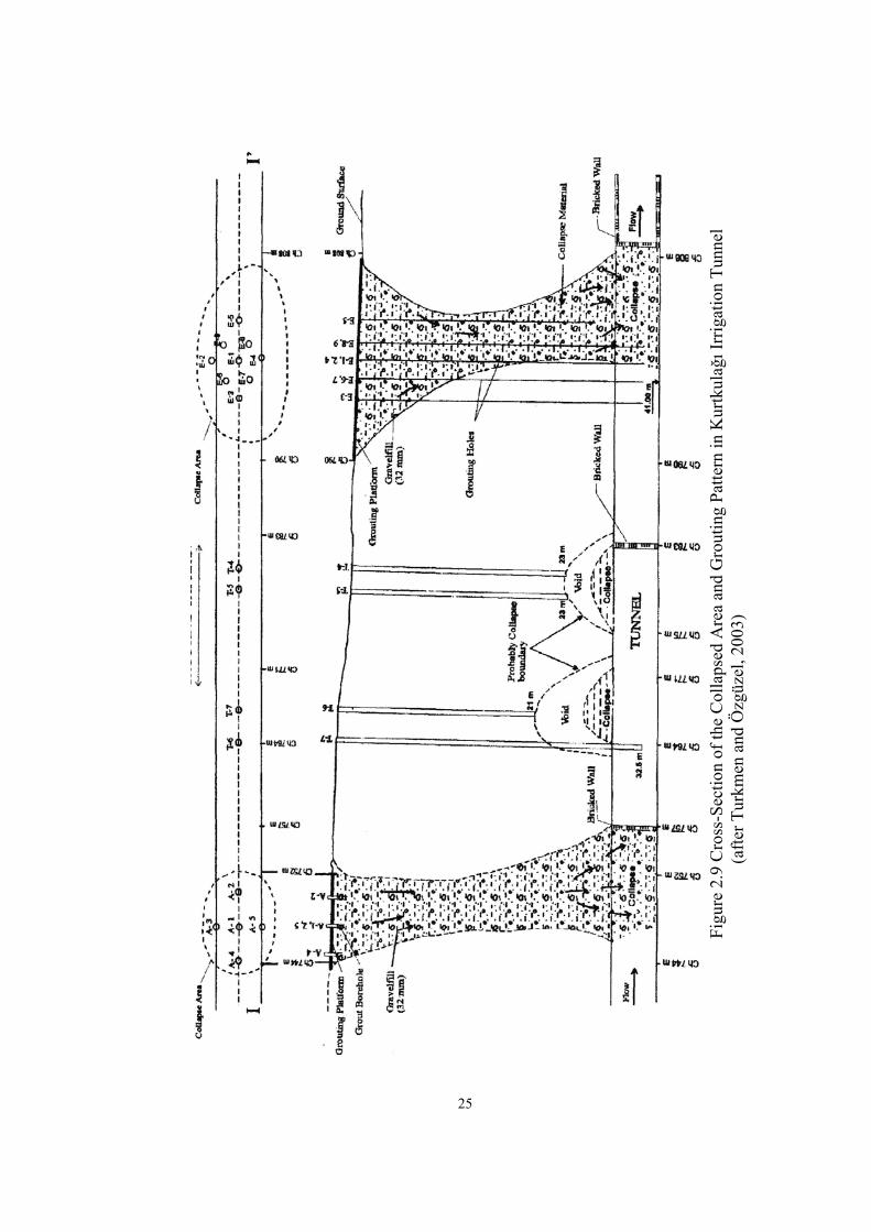
Kurtkulağı Tunnel (Türkmen and Özgüzel, 2003)
Kurtkulağı irrigation tunnel which is 1255 m in length and 3.50 m in
diameter, is an important part of the Yumurtalık Plain Irrigation Project. The tunnel
was excavated using conventional drill and blast, but some tunneling problems
occurred as illustrated in Figure 2.8.
(a) (b)
Figure 2.8 (a) View of the Collapse in the Tunnel Face (b) View of the Sinkhole Form at the Surface
(after Türkmen and Özgüzel, 2003)
During the tunnel advance a fault zone of approximately 150 m was
encountered. During excavation two major collapses occurred between chainage
744-810 m in a fault zone even reaching the ground surface where sinkholes were
formed as demonstrated in Figure 2.9. Tunnelling was being performed at both sides
of the fault zone, the tunnel faces collapsed. Collapse of the tunnel face continued
during removal of the muck material from the tunnel. Consolidation grouting was
applied to prevent collapsing, but it failed because this zone consists of the clayey
material. During the removal of the collapsed material, the tunnel arch collapsed and
two major sinkholes at the surface and several collapses in the tunnel formed.
24
Figu
re 2
.9 C
ross
-Sec
tion
of th
e C
olla
psed
Are
a an
d G
rout
ing
Patte
rn in
Kur
tkul
ağı I
rrig
atio
n Tu
nnel
(af
ter T
urkm
en a
nd Ö
zgüz
el, 2
003)
25
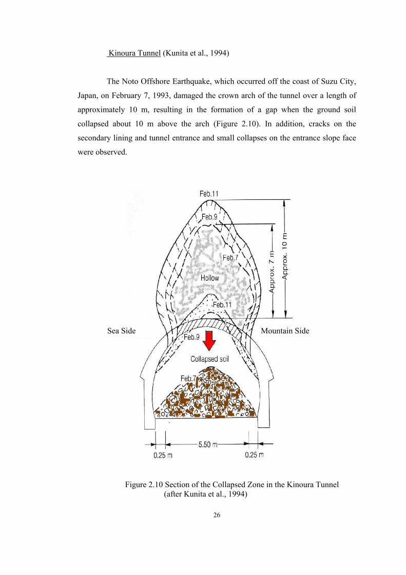
Kinoura Tunnel (Kunita et al., 1994)
The Noto Offshore Earthquake, which occurred off the coast of Suzu City,
Japan, on February 7, 1993, damaged the crown arch of the tunnel over a length of
approximately 10 m, resulting in the formation of a gap when the ground soil
collapsed about 10 m above the arch (Figure 2.10). In addition, cracks on the
secondary lining and tunnel entrance and small collapses on the entrance slope face
were observed.
Sea Side Mountain Side
Figure 2.10 Section of the Collapsed Zone in the Kinoura Tunnel (after Kunita et al., 1994)
26

2.3.2 Sinkhole
In formation of the common and particularly hazardous cover-collapse
sinkhole, a subsurface void forms in soil above an opening in the underlying rock.
The void ultimately propagates to the surface, resulting in subsidence and generally,
formation of a surface pit (Tharp, 1999). Typical examples of sinkholes have been
shown in previous sections (See Figure 2.9 and 2.10).
Factors Associated with Sinkhole Formation (Tharp, 1999)
In some areas most induced sinkholes results from lowering of the water
table, generally to below the soil-rock contact. This condition is conducive to
sinkhole formation as a result of loss of buoyant support, increased pore pressure
gradients and increased amplitude of water level variations. The soil may be
exposed to repeated saturation and drying and the soil may become dry and friable.
Desiccation of this kind may be important in formation of natural sinkholes
associated with natural regional lowering of the water table over geologic time, but
it probably does not occur in many cases of anthropogenic water table lowering. It is
significant that sinkholes can appear very quickly in response to groundwater table
lowering. According to Tharp (1999), Bengston (1987) observed that almost all
sinkholes associated with a 3-day drawdown episode occurred within a day to a few
days. Formation of sinkholes during and after rains is common, often in association
with other causative factors. According to Tharp (1999), Gertje and Jeremias (1989)
describe sinkhole formation associated with a modest rain following a prolonged
drought. Leakage from water supply or drainage pipes is also a common sinkhole
cause.
It is significant that sinkholes form after relatively brief exposure to
changes in hydraulic regime, but it is interesting that they also are precipitated by
loading events of even shorter duration or smaller magnitude. Dynamic loading
commonly causes sinkholes. Blasting is a common trigger for sinkhole formation.
Vibrating equipment and vibro-compaction cause sinkholes, as can even small
earthquakes.
27

2.3.3 Subsidence
Nature and Occurrence of Subsidence due to Tunneling
The occurrence of subsidence during the driving of near-surface tunnels,
especially those connected with urban transport schemes is fairly common feature.
The construction of subway schemes in major cities world-wide has resulted in
measurable subsidence, some of which has been sufficient to cause appreciable
damage to surface structures (Whittaker and Reddish, 1989).
Subsidence above such tunnels is related to the following main factors:
i. The type of ground between the tunnel and the surface
ii. The method of tunnel drivage, together with phasing and degree of permanent support.
iii. The dimensions of the tunnel
iv. The depth of the tunnel below the surface
v. The stress conditions
Ground Conditions
Shallow tunnels are usually driven in soft ground conditions that
necessitate special considerations to be given to temporary support. The generally
weak character of the tunnel gives rise to proneness for roof falls to occur, where a
highly effective and efficient means of temporary support is employed and even
where such well-designed support schemes exist, the occurrence of significant
quantities of water can lead to cavities forming which could result in subsidence
(Whittaker and Reddish, 1989).
According to Whittaker and Reddish (1989), Donovan Jacobs (1985) has
discussed tunnel failures particularly in respect of ground collapses that resulted in
subsidence holes appearing at the surface, and draws attention to experiences with a
serious collapse encountered in the construction phase of a highway tunnel in
Hawaii. In this latter case it was demonstrated that tunnel excavation in soft ground
28

demanded substantially increased attention to safety precautions as compared to
tunnels of equivalent size in solid rock. In the Wilson Tunnel’s collapse water
appeared to play a role in causing the tunnel roof instability to occur which led to
fairly rapid appearance of these sinkholes at the surface and is a particular
characteristic of collapse behavior of unconsolidated clay materials (Whittaker and
Reddish, 1989).
Drivage Method
The method of tunnel drivage whether hand excavated, drill and blast or
machine driven usually results in some delay between excavation and support
application unless a shield allows complete elimination of this excavation-support
delay phase of the drivage operation. Irrespective of how well tunnel drivages are
planned and carried out, there is always a strong likehood that the operations
themselves will allow the opportunity for some subsidence to occur if the other
factors are favorable to its development. However in the majority of the situations
the accompanying subsidence is likely to be of no significance in respect of its effect
on the surface, where a major roof fall occurs in a shallow tunnel, there is a risk of
collapse propagating and a conical depression or even a well-defined subsidence
hole appearing at the surface (Whittaker and Reddish, 1989).
Excavation Size
Tunnel excavated dimensions play a major role in influencing the likehood
of subsidence developing at the surface. The greater the tunnel width, the greater the
imposition placed on the immediate roof to offer self-supporting ability. Since the
tunnel experiences its largest convergence control becomes more difficult as the
tunnel width increases. Effective application of temporary support measures
decreases with increasing size of tunnel, and consequently calls for special care
during the drivage of such tunnels in weak ground (Whittaker and Reddish, 1989).
29

Tunnel Depth
The depth below surface is a major influencing factor on the likehood of
subsidence occurring at the surface above a tunnel. Clearly, if the tunnel is
sufficiently deep, then even the effects of major roof falls may peter out before
reaching the surface (Whittaker and Reddish, 1989).
Stress Field
The nature of the in-situ stress field can play a role in influencing the
stability of near-surface tunnels and consequently their potential for the occurrence
of subsidence. In most situations, however, the state of stress will be governed by
the overburden loading and groundwater conditions thereby giving rise to a
predominantly vertical stress field. In some circumstances high lateral stresses can
exist by virtue of the geological history of the rocks through which the tunnel is
driven and could give rise to stability problems in high tunnels. The conditions
favoring high lateral stress fields are generally encountered in semi-competent and
competent rock situations. High lateral stresses in shallow tunnels can result in
premature failure of natural beams of rock spanning recently excavated tunnels; this
can lead to surface subsidence occurring unless tunnel support is effective
(Whittaker and Reddish, 1989).
2.3.4 Slope Tunnels
Precautions and supporting techniques of tunnels, excavated in soil or rock
formations, differs due to the stipulations of the surrounding. How inconvenient the
stipulations are, so influential would be the problems faced both in designing and
construction stages. A tunnel passing through a slope of a hill, or with it is known
name slope tunnel is one of these conditions presented by nature (Vardar et al.,
2002).
30

It is a known fact that the stability of the tunnel would be affected in a
negative manner if the ground thickness over it were not enough. Similarly, if the
thickness of rock cover is not enough on one side, slope tunnels cannot maintain
their stability anymore and unload their inner energy, which will cause large
deformations. This condition necessitates additional supporting and improvement
works. To prevent excessive deformation of the excavation hole, special supporting
elements should be used and a detailed monitoring program must be used to secure
stability (Vardar et al., 2002).
The most of the important theme of slope tunnels is the thickness of the
pillar between the tunnel and slope of the hill. As the pillar gets thicker, the safer the
tunnel be excavated (Vardar et al., 2002).
2.4 Rehabilitation and Improvements of the Tunnels
Rehabilitation and improvement of the tunnels during the work of the
stabilization of the problematic tunnels, some kinds of techniques are used. In this
part of the literature survey these kinds of case studies are studied and explained in
the following order, namely;
2.4.1 Shotcrete, Bolting and Mesh
Remodeling and Reconstruction of Tunnels
Because of additional clearance requirements of electrification of railway
lines and the construction of additional tracks, a tunnel carrying such lines has to be
reconstructed. Although less frequently, a tunnel may also have to be reconstructed
because of damage caused by subsidence, breakdown and excessive blasting
(Szechy, 1973).
31

Reconstruction for Operational Demands
In order to accommodate a second track, the tunnel section may be
widened on both sides, in which case the existing lining is not to be demolished until
the new one has been completed. This method is most practicable when working
under poor soil conditions and considerable pressures. Work can be started from a
top heading above the crown line, with excavation proceeding from the top and then
constructing the lining in an uninterrupted sequence from the bottom or from drifts
at the bottom of the section. In the latter case the new lining must be constructed in
lifts following the excavated height of the drifts. The first method is limited to firm
soil conditions, the second can be used in poor soil as well (Szechy, 1973).
It is also possible to widen the tunnel section to one side. This is feasible
only in grounds having considerable strength; the existing arch has to be supported
temporarily at the joint with the new lining (Szechy, 1973).
The enlargement and remodeling of underground tunnel profiles is a much
more difficult task owing to usually difficult groundwater and soil conditions and to
the restricted area in which traffic is to be maintained without interruption (Szechy,
1973).
Old double track tunnel of the City and South London was enlarged to a
width of 9.0 meters from 7.5 meters, new tunnel in the relatively reliable London-
clay where no ground water was encountered. The annular space around the
circumference was excavated by hand and the new lining segments could be placed
one by one through the opening left by the demolished and removed elements of the
tunnel while the track was supported step by step by the new concrete pillars placed
on the new invert. Rigid ties offer a great help not only in assuring rigidity of the
partly demolished and incomplete lining rings, in offering supports for various
working platforms (Szechy, 1973).
32

A shotcrete lining provides a surface, the steel ribs acts as linewise support,
whereas rock bolts are effective in a pointwise manner. Steel ribs combined with a
shotcrete lining seem to be attractive for two main reasons:
i. The erection of a steel rib requires only 15 to 20 minutes. The space between the flange and the rock is wedged or shotcreted immediately
ii. The spraying of the shotcrete lining takes more time and the curing of the concrete also needs 5 to 8 hours to attain sufficient compressive strength.
If the shotcrete lining is acting only as a membrane (theoretically), i.e.
subjected only to normal forces and not to bending moments, its load-bearing
capacity is extremely high. Unfortunately, two factors are in play rendering the
shotcrete lining almost useless under the conditions of squeezing ground behavior
(Kovari and Status, 1996):
i. Due to its high stiffness shotcrete cannot accommodate rock convergence to obtain relief of rock pressure
ii. Due to its lack of tensile strength the shotcrete lining fails for even small excentricity of the normal force, i.e. in the presence of bending moments
While special types of steel ribs can be connected with each other to form a
yielding joint and despite retaining a controlled load bearing capacity the shotcrete
will just fail. In order to overcome this difficulty it was proposed to include
longitudinal slots in the shotcrete at the location of the yielding connections of the
steel ribs. The results of this measure are three-fold (Kovari and Status, 1996):
i. No fracture of the shotcrete lining takes place.
ii. The shotcrete will bridge the short distance between the ribs.
iii. The shotcrete lining entirely loses its lining resistance contributing nothing to stabilize the rock
Shotcreting should be performed as promptly as possible as the preliminary
support, the principal purpose of which is to extent the stand-up time of the ambient
33

rock itself, thereby permitting the construction of the performing, i.e. secondary,
support (Zhen-Yu, 1986).
2.4.1.1 Examples of Rehabilitated Tunnels
Malatya-Narlı No:7 Railroad Tunnel (Divleli and Unal, 2005)
Divleli and Unal (2005) presents a case study associated with the
rehabilitation of the Malatya-Narlı No:7 Railroad Tunnel. The rehabilitation work
includes cleaning of two collapses and stopping of deformations occurring in the
tunnel as well as characterizing the rock-mass by evaluating the cores obtained from
50 drill holes.
Tsukayama Tunnel (Asakura and Kojima, 2003)
Tsukayama tunnel was constructed in 1967, with a total length of 1766 m,
as a double-track railway tunnel. The thickness of lining is 0.50 m and invert
concrete was not installed.
Shortly after completion, the tunnel deformed in such a way that both
sidewalls were pushed into the tunnel space accompanied by mud-pumping at the
tracks and heaving at the base. The arch crown was pushed upwards and failed in a
bending and compressive manner. As a countermeasure against this deformation,
invert concrete was installed to close the tunnel section.
In 1990 a wide area of the crown settled where compressive failure had
occurred and many shear cracks developed in a radial manner with their center at the
settled part. The possible collapse of the area was a serious concern. Thus,
preventative work against a collapse of the area was taken immediately as a
temporary measure. As permanent countermeasures, backfilling, rock bolting,
reinforcement and shotcreting with steel fibers were applied, as shown in the Figure
2.11.
34

Figure 2.11 Outline of the Countermeasures in Tsukayama Tunnel
(after Asakura and Kojima, 2003)
La Nerthe Railway Tunnel (Nasri and Winum 2005)
Nasri and Winum (2005) explain rehabilitation of the La Nerthe Tunnel on
the Paris-Maseille High-Speed Railway Line. This 4638 m long double track tunnel
was built at the middle of 19 th century under a maximum cover of 180 m and
currently is used as part of the high speed railway line (TGV). This masonry tunnel
with hard limestone blocks at the sidewalls and bricks at the crown passes through
marl, gypsum and limestone zones. A major fault with accompanying extensive
tectonic deformations cuts across the tunnel axis. The in situ stress tests performed
on the new high-speed rail line in the zone with intense tectonic fractures, tectonic
residual stresses with very high lateral earth pressure coefficients. Nerthe tunnel
underwent ovalization deformation with excessive displacement at the springline
and pinching and bursting of the bricks at the crown. Nasri and Winum (2005)
describe the geological context, damage to the tunnel lining as well as the
rehabilitation system and the constraints of work.
35

The Sidi Mezghiche Tunnel (Panet, 1996)
During the excavation of the tunnel, large convergence of the walls of the
tunnel were measured; displacemensts were typically around 0.10 m and reached up
to 0.25 m in the most unfavorable sections. The convergence of the section was
measured in an unstable section and they increased almost linearly with time. And
finally rock-fall occurred. Before the collapse, the support of the tunnel consisted of
H steel sets (HEB 160 according to ANFOR code) at 0.80 m spacing with a
theoretical 0.15 m thickness of shotcrete; in fact the ring of shotcrete was thicker.
The invert was reinforced by steel sets (TH 36/48 according to the ANFOR code).
The final 0.40 m thick concrete lining was not installed. After the collapse, several
finite element models based on the convergence-confinement method were studied
in order to explain the instability. Some shear tests were carried out to try to
determine the residual shear strengths. From these back-analyses the geotechnical
characteristics in Table 2.1 were obtained.
Table 2.1 Geotechnical Characteristics of the Material
Geotechnical Characteristics
Short term Long term
Deformation modulus (MPa) 100 50
Cohesion (kPa) 90 0
Angle of internal friction 17 10
For the natural state of stress, horizontal to vertical ratio (Ko) value was
taken equal to 1.0. Then, the shape of the cross-section was modified. The support
consisted of H steel sets (HEB 200 according to AFNOR code) at 0.80 m to 1.0 m
spacing and 0.40 m of shotcrete. The invert was closed immediately after the
excavation. The thickness of the reinforced concrete lining was 0.65 m.
36

2.4.2 Rock Mass Improvement
According to Pelizza and Danielle (1993) soil and rock improvement and
reinforcement techniques are applied to permit safe tunnel excavations in difficult
geological conditions. These techniques are used to modify the stresses around the
underground works and the geotechnical parameters of the soil. The main methods
used in Italy and abroad are:
i. Ground reinforcement
ii. Grouting
iii. Jet grouting
iv. Ground freezing
v. Mechanical precutting
Each intervention involves a different approach to the weak soil tunneling
problem, because each modifies one of the different parameters involved within
different technological solutions. The choice of the technique depends on the soil
geotechnical characteristics and on the economical balance between the cost of the
intervention and the benefits it can offer. With regard to their effect on the soil, the
interventions can be divided into two groups:
1-Interventions that improve the soil
2-Interventions that preserve the soil.
2.4.2.1 Soil Improving Intervention
The following interventions produce an improvement in the geotechnical
characteristics of the soil around the excavations (Pelizza and Danielle, 1993).
37

Ground Reinforcement
It is a lasting intervention that is carried out by introducing structural
elements more resistant and rigid than the soil (e.g., bolts, steel cables and steel or
fiberglass pipes) into the ground itself (Pelizza and Danielle, 1993).
Grouting
A lasting intervention that produces its effect by injection of grout mixes
into the soil, at a 20-40 bar pressure. The mixes fill the voids of the soil, thereby
reducing the permeability and improving the soil geotechnical parameters. The grout
mixes can be cement or chemically based (Pelizza and Danielle, 1993).
Jet Grouting
It is a lasting intervention that is carried out by injecting cement-based
grout mix into the soil at a high pressure (over 200 bars). Different injection layouts
have been developed. The final result is a column of treated with better geotechnical
characteristics than the ground itself (Lunardi 1992, in Pelizza and Danielle 1993).
Drainage
It is a lasting intervention that can be applied when water is the main
problem. Drainage system is carried out by reducing the water pressure and
controlling the water inflow with drains of different shafts and topologies (Vielmo
1991, in Pelizza and Danielle 1993).
Freezing
It is a timely intervention that can be applied when the soil is saturated
with soil. The aim of this technique is to excavate the tunnel in frozen ground, which
38

is stable. When the final support is in place, the freezing action is stopped
(Gallavresi 1991, in Pelizza and Danielle 1993).
2.4.2.2 Soil Preserving Intervention
These interventions prevent the parameters of the soil from falling to the
residual values; they allow little disturbance to the stresses around the excavation.
The technological aim of these interventions is to reduce the deformation as much as
possible. Some preserving interventions are briefly described below.
Cellular arch
It is used for short and large underground excavations. A supporting
structure is made before the excavation is carried out. This technique can be
successfully applied in cases where the coverage is so thin that it does not permit the
use of other supporting techniques.
The principal structure support of this system is composed of large
diameter pipes inserted into the ground around the crown and parallel to the
longitudinal axis of the tunnel. The pipes are then filled with concrete and joined
with transversal elements (Lunardi et al., 1991; Focaracci 1991, and Pelizza 1991, in
Pelizza and Danielle, 1993).
Advance Precutting
It is a lasting intervention that is carried out with the excavation of a
preventative “tile cut” around the tunnel, using a chain-saw blade machine. The cut
is filled with a steel–fiber-reinforced concrete lining of high mechanical
characteristics (Lunardi 1991, Arsena et al., 1991, in Pelizza and Danielle, 1993).
39

Jet Grouting Arch
An arch of sub-horizontal columns is carried out at the crown of the future
tunnel. Subvertical columns are often placed in the walls of the tunnel. The arch acts
by supporting the soil during the excavation and by homogenizing the stresses on
the final supports (Pelizza and Danielle, 1993).
Steel Pipe Umbrella
An umbrella of steel pipes with a truncated cone shape is constructed
above the crown of the future tunnel (Carrieri et al., 1991, in Pelizza and Danielle,
1993).
Preconsolidation of the Excavation Face
A timely intervention carried out by inserting fiberglass pipes on the face.
This method is often coupled with a precut or pipe umbrella. This intervention acts
both by reinforcing the ground to be excavated and by preventing movement of the
face. These last two interventions have both an improving and a preserving action
(Pelizza and Danielle, 1993).
2.4.2.3 Examples of Soil and Rock Improvement Techniques in Tunnels
Grouting
In Pelizza and Danielle’s paper (1993), information is given on grouting
application. A double-track tunnel with low overburden was excavated having a
length of 430 meters and excavation diameter of 8.8 meters. The rock mass
consisted of silty sand and sandy gravel. Problems experienced included incohesive
soil requiring prevention in order to stop the movements of the foundations of the
buildings at the surface. Intervention made in the tunnel includes grout injection
40

carried out from the pilot tunnel. The grout mixture consists of both cement and
suitable chemicals. Figure 2.12 shows the grout application pattern.
The following steps were adopted in the operative scheme:
i. The pilot tunnel was bored using a 3.2 m. diameter TBM.
ii. The grouting was carried out by radial injection
iii. The upper half section was excavated and supported with steel arches
iv. (1 m spacing) and shotcrete (0.20 m thick) with wire mesh.
v. The lower half section of the tunnel was excavated.
vi. The invert arch was carried out and the final lining was cast.
B A
C CA
BC: Final lining
A: Pilot tunnel B: Radial injection
21 4 3
1: Injections from pilot tunnel 2: Excavation of half section
3: Excavation of lower part 4: Arch casting
Figure 2.12 Example of Grout Injection Carried Out from the Pilot Tunnel (after Pelizza and Danielle, 1993)
41

Mechanical Precutting
In Pelizza and Danielle’s paper (1993), it is described that a railway double
track tunnel having a maximum overburden thickness of 50 meters and diameter of
12 meters was excavated. The rock mass consisted of clay, sand and sandy clay.
Problems experienced during excavation included large deformations occurring due
to swelling of clay as well as large face deformations. Intervention made in the
tunnel included a 3.5 meters long precut, using steel-fiber-reinforced concrete in a
tile shape. The face was reinforced with fiberglass pipes. The operative scheme
adopted involved the following steps:
i. The precut was carried out.
ii. The previously excavated tile was supported with a steel arch.
iii. The tunnel was excavated (3 m of advance)
iv. After a face advance of 10 m, the inverted arch and the face reinforcement were carried out.
Pipe Umbrella
In Pelizza and Danielle (1993), it is also described that in a road tunnel a
pipe-umbrella intervention was used to improve the stability of the tunnel. The
tunnel was excavated at a depth ranging from 2 to 70 meters from the surface. The
cross sectional area of the tunnel was 90 m2. The rock mass consisted of chaotically
mixed moronic and detrital deposits. Problems experienced included instability of
both the tunnel and the face. Intervention made in the tunnel included an umbrella of
steel pipes with a truncated conic surface 12 meters long. The excavated length per
step is only 9 meters. Thus, there is a 3-meters-long superposition between two
consecutive umbrellas. This intervention provides a guarantee against collapse
during the excavation, and homogenizes the deformative behaviour of the tunnel by
redisturbing the stresses of the supports. Figure 2.13 shows the example of pipe
umbrella intervention to improve the stability of the tunnel and the face of a road
tunnel.
42

The operative scheme consisted of:
i. Placing and injecting the pipes
ii. Reinforcing the face with fiber glass pipes
iii. Excavating the upper half section
iv. Putting in place the steel arches and shotcrete (repeated for 9 m)
v. Supporting the steel arch feet with micropiles
vi. 6-Excavating the lower part of the tunnel
vii. Casting the inverted arch and the final lining
A: Sub-horizontal umbrella pipes B: Twin steel ribs C: Shotcrete D: Wire mesh E: Lateral micropiles F: Subvertical jet columns G: Drainage pipes H: Concrete lining
Figure 2.13 Example of Pipe Umbrella Intervention to Improve the Stability of the Tunnel and the Face of a Road Tunnel (after Pelizza and Danielle, 1993)
43

Kızlaç Tunnel (Etkesen et al., 2002)
Initially, capacity of support applied previously for crown and walls of first
collapsed area was controlled and the cavities above the tunnel verified. Grout is
applied around first collapse area.
At the area affected by the collapse, a self-supporting arch with thickness
of minimum 6 m was established by grouting. The length of arch along the tunnel
profile was 18 m.
The area above the tunnel crown affected by the first and second collapse
were investigated by core drilling (vertically from ground surface) for voids. Open
voids found with in a maximum height of 30 m above the tunnel were filled.
Because rock mass was weathered sandstone, siltstone and shale, grouting
achieved success at the fault zone and outside fault zone.
The aim of grouting was to form a consolidated arch in the loose material
above the tunnel crown with a minimum thickness of 6 m, in order to be able to
advance through the collapsed area. The first grouting sequence covered a length of
18 m. But according to data obtained from forepoling and bore drillings some
additional grout works were done where required.
Grouting created and injected area to prevent excessive flow in the tunnel.
Middle of the tunnel was grouted from side drifts in order to form a grouted body.
Quality and efficiency of treatment were investigated. For this purpose,
core drilling, check of grout intake and rock bolt pullout tests were carried out.
Controls were done to see if there exist any cavities or loosened ground laterally or
vertically.
44

The Kızılay Tunnel (Özaslan et al., 2002)
A 120 m long stretch of the Kızılay tunnel is formed of alluvial deposits
represented by the mixture of clay, silt, sand and gravel. Soil improvement was
recommended over this section in order to contribute to the tunnel stability through
stabilizing the poor soil and to maintain safe working conditions. Jet grouting was
employed for soil treatment since this method was relatively rapid and practical.
Soil improvement was made in a 120 m long stretch of the Kızılay tunnel
passing through the alluvial deposits and existing below the groundwater table.
The crown and sidewalls of the tunnel are stabilized by means of grout
columns. Curtain walls intersecting the tunnel route at right angles were constructed
at an interval of 25 m in order to minimize the amount of water leaking form the
space between the grout columns and to maintain the stability of the tunnel. Grout
columns were made about 0.80 to 0.85 m in diameter.
The most significant problem encountered in the course of the jet grouting
application is the displacement-taking place in the neighboring buildings as a result
of the high pressure grouting since the tunnel route passes through densely
populated areas.
These displacements take place when the grout pressure finds a suitable
path and spreads through the sandy levels within the alluvium and finally reaches
some locations of porous medium, which can be controlled by no means. The jet
grouting is applied through one of the three holes drilled at the corners of an
equilateral triangle with sides 0.80 m long. In order to avoid the displacements, two
holes were drilled and left as relief holes prior to the grouting procedure.
45

Selatin Tunnel (Bizden and Murat, 2002)
After pumping out of the water from the collapsed part of the tunnel, face
covered with wire mesh and shotcrete applied. Later on rock bolts were placed. The
roof of the tunnel, emptied as a result of the collapse, was filled with concrete and
cement injection. Perforated pipes were driven into periphery and cement was
pumped in. Thus, the peripheral rock mass were stabilized. As a result, it became
possible to have a peripheral ground of about 10-15 m stabilized with concrete and
cement around the tunnel. The distance between supports decreased to 0.75 m and
twin W4x13 profiles have been used as supports. In one round 8 m, for the
following round 12 m 15 PG rock bolts were used.
Samanalawewa Tunnel (Hagenhofer, 1990)
The geology of the Samanalawewa site consists of entirely of
metamorphosed crystalline precambrian rocks. Sandy/gravelly areas were densely
compacted, the clayey/sandy silt was generally stiff to firm, with uniaxial
compressive strengths estimated in the range of 60-80 kPa. However, in contact
with water the soil underwent a rapid decrease in material strength, becoming soft or
very soft, flowing ground. There was no support class defined to cope with soft
ground conditions. Therefore, the work cycle had to be changed completely to
implement the new soft ground tunneling concept. In this method, regular holes
were drilled to relieve water pressure in cases of excessive pore water pressure.
Weak and running rock masses were stabilized by applying shotcrete. The
convergence quickly reduced with the application of the new system. No further
collapses occurred after the introduction of the new system.
Kurtkulağı Tunnel (Türkmen and Özgüzel, 2003)
In the Kurtkulağı irrigation tunnel several problems occurred during the
tunneling. Within 70 m long section of the tunnel, collapses occurred at two
locations both occurred along the fault zone in tunnel alignment. A sinkhole was
46

formed at the surface as a result of collapse. Collapses in the tunnel filled by
concrete and the sinkholes were also filled with gravel as the muck was being
removed.
Filling was continued until the sinkhole was completely filled with gravel.
Then, the two sides of the collapsed area were closed with brick walls and grouting
was carried out from the surface. Long (L=1.5 m) grouting pipes were installed in
gravel. The grouting mixture is made of 7/5 (cement/water)+50% sand +2-4%
bentonite.
Jiulongkou Coal Mine (Song and Lu, 2001)
Some of the supports in the permanent access tunnel of the Jiulongkou Coal
Mine had failed and large deformations were observed as shown in Figure 2.14.
Figure 2.14 Some Failed Tunnels in Jiulongkou Mine (after Song and Lue, 2001)
47

In recent years, the supports of the southern main access tunnels were
repaired with steel sets and timbers. The standing duration was only approximately
12 months for steel sets and 3 months for timbers after each repair. Therefore, it was
decided to perform repair of the deformed tunnels with a new approach.
According to the studies, it was concluded that the larger the enlargement,
the greater the further dilatancy deformation, and the more difficult stabilizing the
tunnel will be. The support measure, such as rock bolt, mesh and shotcrete are
adopted based on above concept in repair of the deformed tunnel.
At the Jiulongkou Mine, the rock masses are generally soft rocks, and
therefore development of the loosening zone takes a considerable time. Therefore,
supporting the deformed tunnel was implemented in 2 stages. In the first stage,
flexible support was applied to accommodate the dilatancy deformation during
development of the loosening zone. In the second stage, stiff support was applied to
provide a strong supporting reaction and to maintain the long term stability of the
tunnel.
Based on their engineering practice for the soft rock at the project site,
when the advance distance is 0.6 and 1.2 m roof collapse can be avoided during
enlarging and repairing.
Steel bolts, shotcrete and mesh were used as the supporting measures. Split-
tube steel bolts were applied on the roof and sidewalls. The bolt spacing was 0.5 m
and the bolt length was 1.8 m.
The total thickness of shotcrete applied was 120 mm on average and was
sprayed as 3 layers. The final layer was 50 mm in thickness and was sprayed after
the surrounding rock mass became stable.
The total thickness was used together with shotcrete to increase the tensile
and bending strengths of the shotcrete.
48

Dorukhan Tunnel (Akçelik et al., 2002)
Dorukhan Tunnel’s concrete lining and pavement were heavily damaged;
illumination and ventilation systems could not be established due to the lack of
waterproofing. Vertical area also was not enough.
Tunnel location is near North Anatolian Fault Zone and was driven in
phyllite-metasiltstone and granodiorite which are poor and weathered rock.
Boreholes were driven at the bottom of tunnel to check the rock conditions
during the rehabilitation. Since rock at the tunnel bottom was highly weathered it
was decided to form a grouted zone, as shown in Figure 2.15 with a depth of
approximately 2.5 m at tunnel bottom along the tunnel.
In order to evaluate the performance of grouting, trial of grouting was
performed in 3 sections having different characteristics.
B ACDCA B
E E
Figure 2.15 Section of Grouting Holes at the Bottom (after Akçelik et al., 2002)
A: Grouting inclined from vertical, located at the bottom of the tunnel (L=4.83)
B: Grouting perpendicular to the bottom of the tunnel, located 1.0 m apart from the
wall of the tunnel
49

C: Grouting perpendicular to the bottom of the tunnel, located 2.6 m apart from the
wall of the tunnel
D: Grouting perpendicular to the bottom of the tunnel, located at the tunnel axis
(L=3.1 m)
E: Grouting 65° inclined from vertical, located 0.50 m above the tunnel bottom
(L=3.1 m)
It was concluded that by grouting a reasonable improvement at the tunnel
bottom was maintained. The depth of grouting at the tunnel bottom was increased in
order to obtain a deeper grouted ring in highly weathered rock conditions.
Waterproofing and shotcrete application were performed along the tunnel.
Shotcrete was applied on steel mesh which was reinforced with ø12 mm bars bent in
radial direction with 0.2 m spacing.
Kinoura Tunnel (Kunita et al., 1994)
The Noto Peninsular Offshore Earthquake occurred off the coast of Suzu
City, Japan. As a result of the earthquake, the Kinoura Tunnel was critically
damaged by a collapse of the arch and forced out of service. Because the width of
the excavation in the collapsed zone was greater than the width of the existing
tunnel, excavation was carried out in the sequence as shown in Figure 2.16. During
the excavation of the enlargement zone it was found that the rock mass deteriorated
considerably.
The original lining was removed with a large breaker in 1-m steps, leaving
center core at the face. During the excavation, the ground above the arch fell and the
face in the fallen material collapsed. Therefore, forepoling (l=3 m), shotcreting were
adopted for face stabilization.
Mortar grouted dowel rockbolts were mainly used, although self-drilling
bolts also were used where ground condition were bad.
50

Figure 2.16 Phased Excavation of the Collapsed Zone (after Kunita et al., 1994)
2.4.3 Regeneration of Lining
The deterioration of the tunnel lining is generally considered to be an effect
of aging. In fact, however, it is often related to water leakage. External factors such
as toxic water, frost damage, salt damage and smoke pollution are also operative in
51

some cases. Internal factors include the deficiency of the materials, such as the lack
of cement in the concrete, the insufficient filling of the joints, or in special cases,
deterioration due to an alkali-aggregate reaction (Asakura and Kojima, 2003).
In repairing a deteriorating lining, countermeasures are selected based on
the degree and the causes of the deterioration. It is also necessary, however, to take
into account the locations of the deterioration, the likehood of the drop of lining tips,
and the degree of the critical margin (Asakura and Kojima, 2003).
After an extensive survey of the Negresse railroad tunnel it was decided
that the arch, uprights and floor would have to be repaired in addition to a
straightening of the track and an increase in the gauge (Andrews, 1982).
Work on the tunnel commenced with a preliminary lining of shotcrete 0.07
m deep. This would afford general protection of the site. The shotcrete was
reinforced with a sheet of welded mesh. Once this had been completed systematic
injections of the extrados took place. The injections consisted of a mixture of
cement, fine sand, bentonite and water. It was hoped that they would generate the
lining of the masonry as well as ensuring water tightness. The entire length of the
tunnel was treated through drill holes at a pressure of only 2 bars. A drainage system
was also incorporated into the walls of the tunnel. This consisted of a number of
aureoles in the walls of the tunnel which drained into a common central canal in the
floor (Andrews, 1982).
The roof of the tunnel was reinforced with conventional cast-iron arches.
The cast iron arches were placed in groups of four or five pre-assembled elements
provisionally maintained in place by straps and expanding anchor pins. The
completely assembled ring is finally anchored by 1.5 m long pins and secured by
injections of mortar after plugging (Andrews, 1982).
The arches were placed in conjunction with the reinforced concrete
uprights. The operation was split into two parts, each upright was put in place
52
together with half of the arch, the work was then switched to the other side of the
tunnel and the same repeated. Once this had been achieved the arch was finally
anchored. The arches were placed in groups of four or five pre-assembled elements,
provisionally maintained in place by straps and expanding anchor pins. The
completely assembled ring was finally anchored by pins 1.5 m long and fixed
injections of mortar after plugging. Once this had been achieved the new floor was
placed with a new track (Andrews, 1982).
During the 90 years, various sections of the tunnel had been repaired with a
cast in place concrete arch. In most sections this appeared to be over existing timber
sets. Most of the concrete arches had visible voids and punky areas where the
concrete had decayed and now showed the remains of corroded rebar. These
concrete arched sections were repaired in three steps. First, steel c-channel arches
were bolted into place on 1.2 m centers. Next the steel arches and concrete were
covered with 0.08 m of shotcrete. Finally the voids behind the concrete were filled
with cellular concrete grout. Blocky areas were bolted. The more sheared areas were
supported with a combination of rockbolts, mine straps and shotcrete (Goss, 2002).
The detailed inspection of the tunnels revealed weaknesses in places in the
arching and behind the linings. Some pressure resulted in distortion occurring to
some of the masonry arches within the tunnels. Cement grout was injected under
low pressure to fill the voids and weep holes were made. The old mortar was blown
out by compressed air and the new forced in under high pressure (Goss, 2002).
After the void was concreted, the underlying muckpile was grouted and
stabilized. Finally the remaining adjacent lining in both tunnels was cavity grouted
and fissure grouted and 7 m long rock bolts supplemented with fully grouted dowels
installed between both tunnels (Goss, 2002).
53

Soft Ground
According to Szechy (1973) the rock mass can be divided into four classes
namely: running rock mass, soft rock mass, firm rock mass and self supporting rock
mass. The running rock mass may consists of dry sand or gravel and should be
supported instantly. The soft-rock mass roof should be supported instantly however
the walls could be stable for a short period of time. In the firm rock mass the roof
could stay unsupported for a short time however the side walls and the face could be
stable for a longer period of time. Finally, the self-supporting rock mass can stand
unsupported while the entire tunnel is driven a few meter ahead of the supports.
The standard methods of driving through soft ground are forepoling with
wood or steel, or working in a shield. Plenum method is keeping out soil and water
with air pressure, with either forepoling or shield (Szechy, 1973).
Forepoling: The use of plank forepoles was formerly the standard method
of driving a tunnel through soft ground. While this technique has been largely
replaced by steel liner and poling plates, it is still widely on jobs too small to justify
obtaining steel (Szechy, 1973).
In forepoling, the tunnel is protected by timbering and by breast board set
against the face. Planks are driven through slots cut in the breast board and
supported cantilever fashion to make a temporary roof, under which dirt can be dug
and permanent supports installed (Szechy, 1973).
2.4.4 Tunneling Through Running Ground by Forepoling Method
Material with no cohesion, such as clean sand or gravel is commonly
referred to as running ground regardless of whether it is located below or above the
water table. In running ground, excavation or opening of collapsed part of the tunnel
requires use of the ancient forepoling or one of its modern equivalents (Szechy,
1973).
54

The boards which are driven ahead to support the grounds ahead of the last
rib are known as spiles. They act as cantilevers which carry the weight of the ground
until their forward ends are supported by installing the next rib (Szechy, 1973).
The spiles are installed as far down around the sides of the tunnel as
necessary. Then the top breast boards are removed, the exposed ground is excavated
and the breast boards are reinstalled ahead. This process is continued until the
excavation arrives at floor level, where upon the next rib can be installed. At some
time afterwards the tails of the spiles are cut off (Szechy, 1973).
Tunneling in Raveling Ground
The term raveling ground indicates a ground which can stand up for at least
two or three minutes when an opening approximately 0.91 m wide by 0.41 m
forward is made. However, after this period, it may start to scale off. Slightly
cohesive sand belongs in this category. In the past tunneling through this kind of
ground was done by means of the forepoling method, which is slow, difficult and
expensive. Today, the more expeditious and more economical liner plate method is
generally used (Szechy, 1973).
The installation of liner plates starts at the top center. The top breast board
is removed and an opening just large enough to admit liner plate, usually 0.41 m is
scraped out and the liner plate immediately showed up against the ground. Its rear
flange is bolted to the preceeding course and a block is placed under its leading
edge. The breast board is reinstalled 0.50 m ahead (Szechy, 1973).
Umbrella Arch
Umbrella Arch is usually obtained by means of a series of holes, hole
diameter ranges between 100 and 180 mm, that are drilled, even spaced, along the
contour of the tunnel vault in such a way to form half cone. Similar holes can be
55

drilled, if needed, also along the contour of the sides of the tunnel cross section
(Kadkade, 2002).
In the holes are then placed steel pipes of suitable diameter, perforated
along the lower side; grouting agents are pressure injected in the pipes (Kadkade,
2002).
The umbrella combines the advantageous of modern forepoling system and
of a series of grouting injections. It allows the excavation to progress with a full
control of subsidences through heterogeneous rocks having poor geomechanical
properties as alluvial deposits, moraines, mylonites. A limit to the useful application
of the method is posed only by groundwater under high pressure (Kadkade, 2002).
2.5 Stability Measurements of the Tunnels
Convergence Measurement
The usual laboratory and in-situ tests proved to be insufficient to provide
reliable data at the scale of the rock mass. Limited technique is available to
determine the natural state of stress, the knowledge of which would be essential for
any model. The monitoring of convergences during face advance and the back-
analysis of the measurements appear to be the most reliable approach to provide an
overall assessment of the behavior of the rock mass (Panet, 1996).
Frejus Tunnel (Panet, 1996)
During the excavations of Frejus tunnel, large convergences occurred in
the direction orthogonal to the plane of schistosity. These convergences were
measured with a distometer on about 150 profiles. For each profile, the initial
measurement was carried out close to the face (from 2 m to 5 m), and the
convergences were measured regularly during 3 to 4 months until placing of the
56

concrete lining. The convergences measured were over 0.10 m on many sections; the
maximum value measured for the final convergence was about 0.50 m.
The convergences of a tunnel are to be analyzed taking into account the
immediate convergence due to the advance of the face and the time-dependent
convergence due to the rheological behavior of the rock mass. From the detailed
analysis of the convergences, the following formula was established for the
convergence law in terms of the distance x between the section and the face and
time t:
C(x,t) = A1 ƒ(x)(1+A2 g(t)).......................................[2.1]
For various tunnels, a good agreement is obtained with the following
functions:
f(x)=1-(X/(X+x))2 ..............................................[2.2]
g(t)=1-(T/(T+t))n ..............................................[2.3]
Where x is convergence and t is time. The parameters of this convergence
law are:
i. X which characterizes the distance of influence of the face of the tunnel;
in
the elastic domain, X is equal to 0,375B, B being the width of the tunnel
section and when there is a plastic zone around the tunnel, X is
proportional to the extent of the plastic zone.
ii. T and n are constants depending only on the rheological behavior of the
rock mass.
iii. A1 is the convergence observed for the initial rate of excavation
57

iv. (1+ A2 ) is the ratio between the final convergence and A1 ; it characterizes
the importance of the time-dependent deformations.
In order to stabilize the convergences, the tunnel was supported by
rockbolting and a strong mesh to confine the loose rock between the bolts. The most
extensively used type of rockbolt was φ 20 mm, 4.65 m long anchored rockbolts. In
the most critical areas, the density of bolting was 1.2 bolt per square meter and
various devices were used to increase the yield strain of the bolts and to prevent
their failure. The rate of convergence varied between 0.1 mm/day and 0.5 mm/day
after installation of concrete lining (Panet, 1996).
Significant studies have also been carried out on convergence
measurements and interpretation of the results by Unal et al., in 2001.
In Jiulongkou Coal Mine the first phase of repair work began in mid-1997,
without interfering with normal coal mine production activity, and ended in early
1998. After the first phase repair work repair work and evidence of the effective
results, more repair work has been carried out in other tunnels (Song and Lu, 2001).
A monitoring station was set up during test-phase repair work. Up until
August 1998, the data on tunnel deformation had been taken for over 370 days. It is
evident from the convergence curves of the tunnel that the period of stress
redistribution was approximately 30 days. After the stress had stabilized,
measurements over a further 300 days were taken. These measurements showed that
the maximum convergence was less than 14 mm, and indicate that repair of the
tunnel were successful (Song and Lu, 2001).
For railway tunnels in China, primary stress field and common physical and
mechanical parameters of surrounding rocks are determined by FEM back analysis
on the basis of peripheral displacements measured in-situ. Viscous parameters of
rock mass can be ascertained from further back analysis. Much work also has been
done in investigating and improving measurement instruments. Peripheral
58

displacement measurement instruments of types SWJ-81, SWJ-II, and SWJ-III were
developed in the China Railway research Institute, with nominal mean square error
0.01-0.04. Type SWJ-III instruments also can be used to measure oblique
convergences in the extent of 70° angles (Mi and Shiting, 1989).
A type HW slide resistance displacement measurement instrument; an HJ-
1-type receiver with system sensitivity 0.1 mm/graduation; and a three point
differential transfer type displacement measurement instrument that can be used for
remote measurement of displacements (Mi and Shiting, 1989).
In order to ensure the safety of the supports in the collapsed zone and the
safety of the tunnel during the restoration work and temporary service, series of
measurements were carried out in the reinforcement zone as shown in Figure 2.17
(Kunita et al., 1994).
Inward displacement measured above 5 mm during excavation, but
convergence in several days. Ground displacement was 6-7 mm on the mountain
side and approximated 3 mm on the sea side (Kunita et al., 1994).
The overall results indicated a sufficient level of safety of both the ground
and the supports (Kunita et al., 1994).
Brunswick street rail tunnel was monitored for convergence at the cross
sections below lines of settlement monitoring points. The convergence was
measured using an interfels tape that could be read to 0.01 mm precision. The cross-
sections were read daily, when the face was still close to the monitoring cross-
section, and then at longer intervals as the face moved further away (Asche and
Baxter, 1994).
59

Figure 2.17 Measurements in the Reinforcement Zone (after Kunita et al.,1994)
The results of the convergence monitoring appeared to show some slight
movement initially and then to show virtually no movement after the face had
moved 10 m away. Some long term movement was measured, although it was small
(Asche and Baxter, 1994).
60

CHAPTER 3
GENERAL INFORMATION ON NO: 7 MALATYA-NARLI
RAILROAD TUNNEL
3.1 General
In this chapter, general information about No: 7 Tunnel, geological and
hydrogeological conditon in the vicinity of the tunnel and stability problems will be
summarized.
3.2 General Information About No: 7 Malatya-Narlı Railroad Tunnel
3.2.1 Location of the Tunnel
The nearest town to the tunnel is called Gölbaşı, which is about 7 km away
from the tunnel, and it is located in the west part of Adıyaman. Gölbaşı is
surrounded by Malatya in the north, Besni and Tut in the east, Gaziantep in the
south and Kahramanmaraş in the west. The altitude of Gölbaşı is 862 m. Figure 3.1
shows the location of Gölbasi.
Gölbaşı district is located on the route connecting Blacksea and South
Eastern Anatolia to Mediterranean. It is also located on the route connecting
Malatya, Adıyaman, Gaziantep and Kahramanmaraş to each other. The distrcit’s
economy has been founded based on the advantages of being on the railway and
highway as it is shown in Figure 3.2 and 3.3. 61

Figure 3.1 The Location of Gölbaşı (after www.adiyaman.gov.tr, 2003)
NETWORK OF TCDD
Narlı
Figure 3.2 Turkish Railroad Map (after www.trainsofturkey.com, 2004)
62
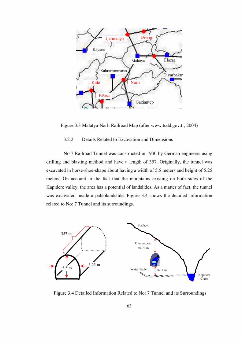
Çetinkaya Divrigi
Kayseri
Malatya Elazıg
Diyarbakır
Narlı
Gaziantep
F.Pasa
T.Kale
Kahramanmaras
Figure 3.3 Malatya-Narlı Railroad Map (after www.tcdd.gov.tr, 2004)
3.2.2 Details Related to Excavation and Dimensions
No:7 Railroad Tunnel was constructed in 1930 by German engineers using
drilling and blasting method and have a length of 357. Originally, the tunnel was
excavated in horse-shoe-shape about having a width of 5.5 meters and height of 5.25
meters. On account to the fact that the mountains existing on both sides of the
Kapıdere valley, the area has a potential of landslides. As a matter of fact, the tunnel
was excavated inside a paleolandslide. Figure 3.4 shows the detailed information
related to No: 7 Tunnel and its surroundings.
Surface
357 m
Overburden 60-70 m
5.5 m5.25 m
Water Table 8-14 m Kapıdere
Creek
Figure 3.4 Detailed Information Related to No: 7 Tunnel and its Surroundings
63

No: 7 Tunnel is located at the back of Alisliseki which is the part of
Kapıdere creek. Kapıdere stretches from North to South direction and flows along
quite rough topography with approximately 250 m wide flood area. But, the creek
passes through bottleneck at the location of No: 7 Tunnel. In this part of the valley,
there is no clear lithological control to prevent occurrence of the flood area.
As shown in Figure 3.5 and 3.6, the riverbed takes place between the right
and left bank of the creek and has been displaced towards left (west) due to
Alisliseki landslide.
The tunnel in question have had some temporary rehabilitation work in
order to reduce or stop deformations and sliding taking place in the tunnel.
However, during the rehabilitation attempts and providing alignment to the slided
tunnel, collapses occurred accompanied with a sinkhole at the surface. Hence, the
tunnel closed to the railroad traffic for about 10 months (September, 2002-July,
2003) during the initiation of Iraq War.
Due to the stopped railroad traffic over Adana and Malatya line the
material transportation was realized over Kayseri, Ulukısla and Adana route. That
compulsory route changing increased the operational expenses in terms of money,
energy and time. The money lost by TCDD was considerable. In addition, the
money lost by steel factory İsdemir, reached to high levels because the iron ore
extracted from Divrigi and Hekimhan was transported through a longer route.
3.3 Geology of the Site
No:7 Railroad Tunnel was excavated within the heel material of a
paleolandslide being accumulated over the old flood area of Kapıdere and eroded
from Alisliseki ridge. The rock mass around the tunnel is melange type having a
complex geology. The rock mass around the tunnel consists of metavolcanics,
schists, fractured limestone blocks, antigorite and radyolite in patches. The matrix
material consists of clay and schist having low swelling potential. Limestone blocks
are generally closely jointed and highly fractured. Pelitic schists around the tunnel
64

have distinct deformations traces and shear deformations around them (Ergun et al.,
2002).
During field studies it was determined that the landslide, having a crest in
some 1140 m. elevation, is a paleolandslide (Ergun et al., 2002). The rock mass
surrounding the tunnel consists of limestones and crystallized limestone pieces
between kilometers 155+453 and 155+663, formed at the crest of this landslide,
while low grade metamorphic rocks and metavolcanics possibly developed in small
blocks at lower parts. However, the rock mass surrounding the tunnel between
kilometers 155+663 and 155+753 mainly consists of metavolcanics and pelitic
schists.
Figure 3.5 The Creek Flowing Parallel to the Tunnel
65

Tunnel
Tunnel
Creek Side
Mountain Side
Figure 3.6 The Location of the Landslides at Right and Left Banks at Kapıdere (after Ergun et al., 2002)
Metavolcanics and schists taking water from limestones turn into smectite
type of clay, having low potential swelling type, by means of hidrotation. The tunnel
takes part in second seismic zone.
3.4 Hydrogeology of the Site
The complex lithological units surrounding the tunnel where very low
permeability schist and metavolcanics taking part as blocks in the matrix material
indicate a medium permeability. However, in the existence of limestone blocks the
permeability level increases due to existence of dense cracks and fractures.
66

3.5 Stability Problems in the Tunnel
No: 7 Railroad Tunnel experienced stability problems ever since the
opening of the tunnel in 1930. The main reason was excavation of the tunnel inside
the toe of a landslide material. In addition, TCDD struggled with the stability
problems created due to two roof-falls, tunnel width decreased due to squeezing,
failure of steel-arches and concrete lining and effect of groundwater.
Morphology of the surrounding of the tunnel clarifies that Kapıdere
riverbed was squeezed by the hillside. The landslide morphology observed along the
Alisliseki ridge and other bank of the creek confirmed the existence of the landslide
as shown in Figure 3.7 and 3.8.
According to geological observations, landslide scarp (crown) takes part in
the east part of the Alisliseki back. Sliding surface ends at the bottom level of
Kapıdere. Limestones taking part in the crown of the landslide with coarse to fine
blocks spreading all the area are observed as floating blocks as shown in Figure 3.9
and 3.10. In addition to limestone blocks, scattered schist and metavolcanic blocks
are observed.
67

Figure 3.7 Alıslıseki Landslide scarp, Swellings and Settlements at the
Mountain Side (after Ergun et al., 2002)
Figure 3.8 Landslide Materials at the Mountain Side (after Ergun et al., 2002)
68

Figure 3.9 Landslide Materials at the Mountain Side (after Ergun et al., 2002)
Figure 3.10 Landslide Materials at the Mountain Side (after Ergun et al., 2002)
69

70
CHAPTER 4
PROBLEMS RELATED TO THE STABILITY OF THE NO: 7 RAILROAD TUNNEL
4.1 Problems Related to the Stability of the Tunnel
The stability problems observed in and around No: 7 Railroad Tunnel can
be categorized into seven main groups, namely;
i. Excessive displacement occurred in the tunnel
ii. Collapses occurred during rehabilitation work
iii. Sinkhole developed on the surface due to roof collapse, and flow of rock material into the tunnel
iv. Reduced tunnel span and height preventing free trains pass inside the tunnel
v. Poor rock mass causing instability in the tunnel
vi. Surface and underground water reducing tunnel stability
vii. Unstable regions requiring urgent repair
4.2 Excessive Displacements Occurred in the Tunnel
An obvious misalignment was observed within 105 meters of the tunnel
between kilometers 155+550 and 155+655 and 35 meter section of it (between
kilometers 155+569.15 and 155+604.15) was displaced about 1.70 meters over the
years. Figure 4.1 demonstrates excessive displacements occurred in the tunnel.

71
Figure 4.1 Excessive Displacements Occurred in the Tunnel
4.3 Collapses Occurred During Rehabilitation Work
The problems in the past include surface and underground water,
deformation, roof rock fall, clay bearing strata and voids existing in the rock mass.
The first collapse in the tunnel (roof-fall) occurred on July 30, 2002 due to breakage
of the existing concrete-lining during enlargement of No: 7 Railroad Tunnel. This
collapsed material flowed from the roof filled a 21-m long section of the tunnel
between km 155+666 and 687 as shown in Figure 4.2. The volume of the roof-fall
material flowed into the tunnel was estimated to be 500 m3. Because of this roof-fall
the tunnel stayed close to traffic for about 10 months.
Malatya Portal
Narlı Portal
km 155+822
km 155+822
km 155+655
km 155+550
1.70 m
Narlı Portal km 155+465
Malatya Portal km 155+822
km 155+569
km 155+604
Misaligned Section
Displaced
Section
km 155+550
km 155+655
km 155+604
km 155+569

72
Figure 4.2 Collapse Area and the Void Developed above the Tunnel
697.65 (231 m)
692 m
689 m
676 m
686.65 (220 m)
Sect
ion
13
Sect
ion
12
Malatya
673 m
669.65 (205 m)
666.65 (202 m)
Section 11
Narlı

73
While cleaning up of the roof-fall material in the tunnel, a new roof-fall
occurred at a 3-meter long section, on February 7, 2003 in such a manner that the
loose material at the roof poured into the tunnel’s cavity as shown in Figure 4.3.
(a)
(b)
Figure 4.3 Appearance of the Roof-Fall, (a) from Malatya Side and
(b) from Narlı Side
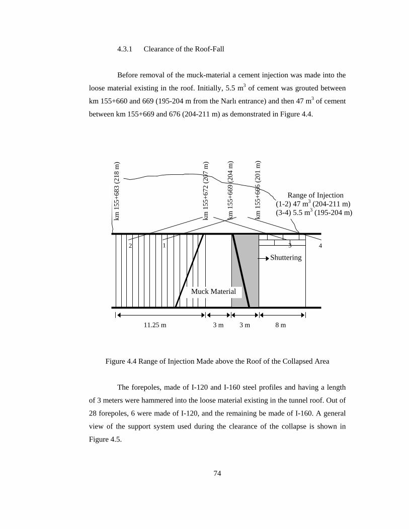
74
4.3.1 Clearance of the Roof-Fall
Before removal of the muck-material a cement injection was made into the
loose material existing in the roof. Initially, 5.5 m3 of cement was grouted between
km 155+660 and 669 (195-204 m from the Narlı entrance) and then 47 m3 of cement
between km 155+669 and 676 (204-211 m) as demonstrated in Figure 4.4.
Figure 4.4 Range of Injection Made above the Roof of the Collapsed Area
The forepoles, made of I-120 and I-160 steel profiles and having a length
of 3 meters were hammered into the loose material existing in the tunnel roof. Out of
28 forepoles, 6 were made of I-120, and the remaining be made of I-160. A general
view of the support system used during the clearance of the collapse is shown in
Figure 4.5.
11.25 m 3 m 3 m 8 m
12 3 4
km 1
55+6
72 (2
07 m
)
km 1
55+6
69 (2
04 m
)
km 1
55+6
66 (2
01 m
)
km 1
55+6
83 (2
18 m
)
Shuttering
Muck Material
Range of Injection (1-2) 47 m3 (204-211 m) (3-4) 5.5 m3 (195-204 m)

75
Figure 4.5 Views of the Support System Used During Clearance of the Collapse
In order to provide an initial stability and a safe working place, 8 steel-sets,
two of which were twin, were installed shoulder to shoulder on the muck material
located between km 155+670 and km 155+676. For this reason, first of all, the muck
material in the both sides of the tunnel walls was removed and cleaned providing a
space of approximately 0.5 m. The top two pieces of the steel-sets forming the arch
were joined to each other from their peak points by using M20x60 mm type bolts.
After this step, the arch parts of the steel-set were inserted into the cavity so opened.
A total of six and four joints or bolts were used in the double and single steel-sets,
respectively.
Furthermore, the steel-sets installed while clearing the bench of the roof-
fall or muck material were connected to each other by using a number of laggings
(or steel-profile brushes). Finally, a steel wire-mesh was installed between the steel-
sets and then the total structure was shotcreted.
The steel-arch profiles were connected to each other by welding with a
horizontal I profile connecting two arch profiles. In addition, two diagonal I profiles
were welded between the horizontal profile and the steel-arch as shown in Figure 4.6
and 4.7.
I-160 and I-120 Steel Profiles
Steel Wire Mesh
Muck Material Muck Material
Steel Set
Steel Set
Laggings

76
Figure 4.6 Bench Support Used During Clearance of the Collapsed Material
Figure 4.7 Installation of the Limp (Short) Leg of the Steel-Arch and of the
Temporary I-Profiles
Steel Wire Mesh
Horizontal Steel Profile
Strut I-Profile
Threaded Steel Bar
Threaded Steel Bar
I-Profile Used as forepoles
Steel Wire Mesh
Muck Material
Strut I-Profile
Threaded Steel Bar
Threaded Steel Bar
I-Profile Used as forepoles
Steel Wire Mesh
Muck Material
Temporarily Installed I-Profile
Steel Wire Mesh

77
The arch part of the steel-set was consolidated in the tunnel wall by
hammering the threaded steel rebars having a length of 2.0 m and diameter of 32
mm. Each rebar was hammered underneath the laggings between two consecutive
steel-sets for the creek and mountain side walls. At this stage, the height and width
of the muck material were 2.0 meters and 4.50 meters, respectively. However, the
height of the muck material to be cleaned at the invert was 3.60 meters.
As a result of the supporting work described in this section, the stability of
the caved area provided as follows:
i. A reaction of reinforcement was provided against lateral loads
ii. The steel-sets were strengthened against sudden loads that might be
exerted from the roof
iii. Measures were taken against the possibility of the steel-arch falling
down. In addition, the legs of the steel-sets were mounted while the
muck material on the floor of the tunnel was removed by using back-
hoe type equipment.
The bottom leg of the steel-arch was completed by welding an additional I-
profile piece beneath the steel-arch.
Using this procedure explained above, the installation of 8 steel-sets was
completed. Initially, it was not possible to put the legs of the steel-sets on the ground
level (floor of the tunnel) as shown in Figure 4.8. In the meantime, two vertical steel
I-profiles were welded temporarily to the horizontally welded I-profile at the
shoulder level. Starting from one side, the muck material on the bottom of the tunnel
was removed.
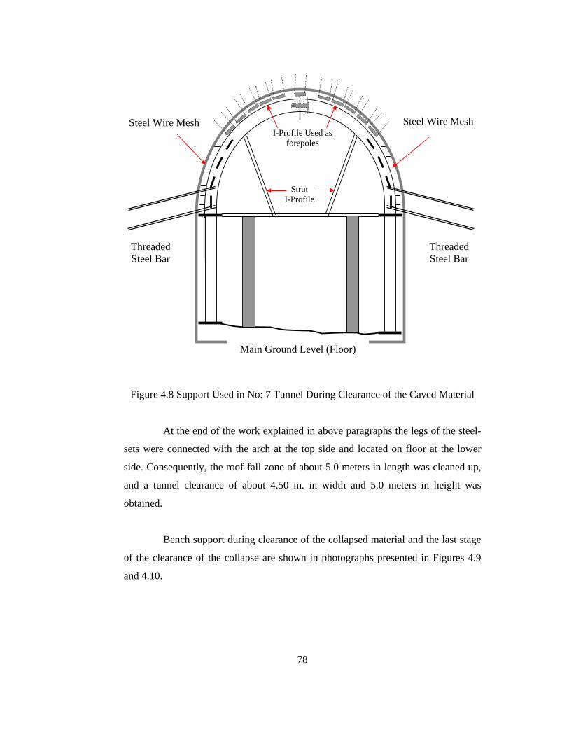
78
Figure 4.8 Support Used in No: 7 Tunnel During Clearance of the Caved Material
At the end of the work explained in above paragraphs the legs of the steel-
sets were connected with the arch at the top side and located on floor at the lower
side. Consequently, the roof-fall zone of about 5.0 meters in length was cleaned up,
and a tunnel clearance of about 4.50 m. in width and 5.0 meters in height was
obtained.
Bench support during clearance of the collapsed material and the last stage
of the clearance of the collapse are shown in photographs presented in Figures 4.9
and 4.10.
Strut I-Profile
Threaded Steel Bar
Threaded Steel Bar
I-Profile Used as forepoles
Steel Wire Mesh Steel Wire Mesh
Main Ground Level (Floor)

79
Figure 4.9 Bench Support Used During Clearance of the Collapsed Material
Figure 4.10 Last Stage of the Clearance of the Collapse

80
4.4 Sinkhole Developed at the Surface due to Roof Collapse and Rock Mass
Flow into the Tunnel
As a result of the two collapses occurred in the tunnel a sinkhole was
developed on the ground surface as a result flow of 500 m3 material into the tunnel
from the tunnel roof. The dimensions of the sinkhole were about 15x10x20 meters.
The sinkhole developed at the ground surface and a sketch of the collapsed area with
the sinkhole developed at the surface are shown in Figures 4.11 and 4.12,
respectively.
(a)
(b)
Figure 4.11 Sinkhole Developed at the Surface as a Result of the Collapse
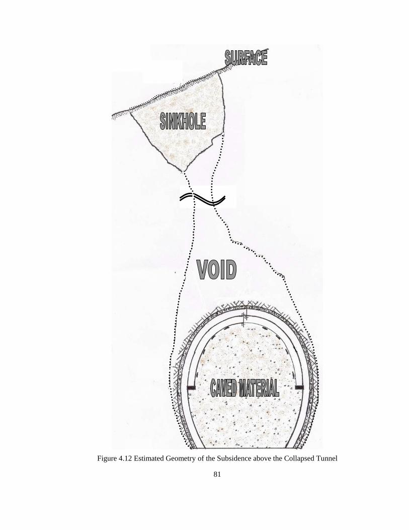
81
Figure 4.12 Estimated Geometry of the Subsidence above the Collapsed Tunnel
111,30
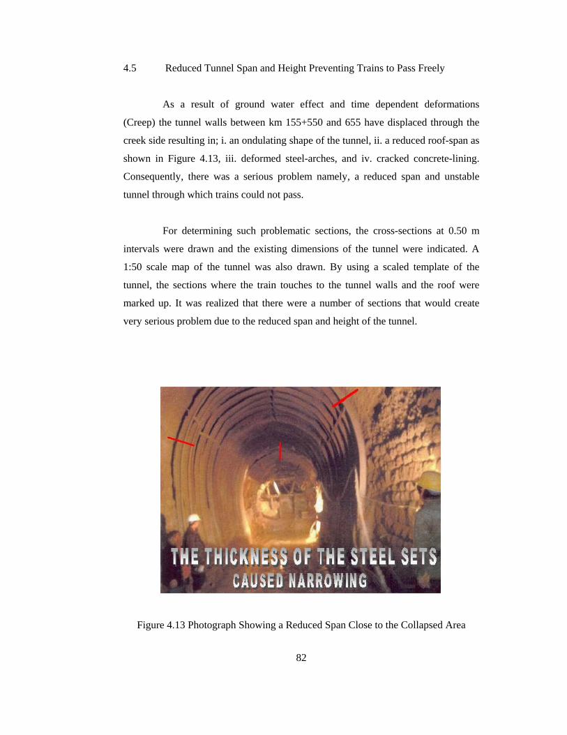
82
4.5 Reduced Tunnel Span and Height Preventing Trains to Pass Freely
As a result of ground water effect and time dependent deformations
(Creep) the tunnel walls between km 155+550 and 655 have displaced through the
creek side resulting in; i. an ondulating shape of the tunnel, ii. a reduced roof-span as
shown in Figure 4.13, iii. deformed steel-arches, and iv. cracked concrete-lining.
Consequently, there was a serious problem namely, a reduced span and unstable
tunnel through which trains could not pass.
For determining such problematic sections, the cross-sections at 0.50 m
intervals were drawn and the existing dimensions of the tunnel were indicated. A
1:50 scale map of the tunnel was also drawn. By using a scaled template of the
tunnel, the sections where the train touches to the tunnel walls and the roof were
marked up. It was realized that there were a number of sections that would create
very serious problem due to the reduced span and height of the tunnel.
Figure 4.13 Photograph Showing a Reduced Span Close to the Collapsed Area
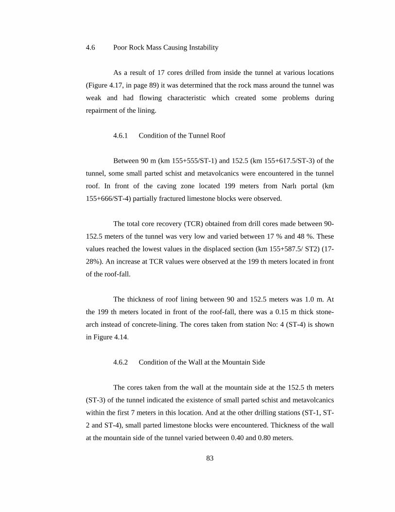
83
4.6 Poor Rock Mass Causing Instability
As a result of 17 cores drilled from inside the tunnel at various locations
(Figure 4.17, in page 89) it was determined that the rock mass around the tunnel was
weak and had flowing characteristic which created some problems during
repairment of the lining.
4.6.1 Condition of the Tunnel Roof
Between 90 m (km 155+555/ST-1) and 152.5 (km 155+617.5/ST-3) of the
tunnel, some small parted schist and metavolcanics were encountered in the tunnel
roof. In front of the caving zone located 199 meters from Narlı portal (km
155+666/ST-4) partially fractured limestone blocks were observed.
The total core recovery (TCR) obtained from drill cores made between 90-
152.5 meters of the tunnel was very low and varied between 17 % and 48 %. These
values reached the lowest values in the displaced section (km 155+587.5/ ST2) (17-
28%). An increase at TCR values were observed at the 199 th meters located in front
of the roof-fall.
The thickness of roof lining between 90 and 152.5 meters was 1.0 m. At
the 199 th meters located in front of the roof-fall, there was a 0.15 m thick stone-
arch instead of concrete-lining. The cores taken from station No: 4 (ST-4) is shown
in Figure 4.14.
4.6.2 Condition of the Wall at the Mountain Side
The cores taken from the wall at the mountain side at the 152.5 th meters
(ST-3) of the tunnel indicated the existence of small parted schist and metavolcanics
within the first 7 meters in this location. And at the other drilling stations (ST-1, ST-
2 and ST-4), small parted limestone blocks were encountered. Thickness of the wall
at the mountain side of the tunnel varied between 0.40 and 0.80 meters.

84
Figure 4.14 Cores Taken from the Roof at Station No: 4

85
Just behind the concrete, there was a weathered clayey matrix with a
thickness of which varied between 0.25-0.60 m. Based on the evaluation of the cores
taken from boreholes drilled in the tunnel it was concluded that rock mass at the
mountain side of the tunnel exhibits of a highly complex structure. At locations
between 90 and 122.5 meters, as from the Narlı entrance, rock mass exhibited
relatively better quality. Its TCR values reached up to 100 % at several locations.
There were only two sections where RQD values were 45 and 55, respectively. The
RQD values were zero in all other locations except these two sections. Typical cores
obtained from different borehole stations are shown in Figure 4.15.
In one of the boreholes drilled at displaced section (122.5 m), it was
observed that especially between the first 1.2-7.5 meters of the drilling, TCR and
Intact Core Recovery (ICR) values were respectively high. These results indicated
the existence of a stronger rock mass behind the tunnel wall exposed to deformation,
which did not exist in the other sections. Rock mass at the 152.5 th meters of the
tunnel was very weak (8<TRC<30; RQD=0) as was the case in most of the other
locations.
4.6.3 Condition of the Wall at the Creek Side
The drillings made towards the wall at creek side, between locations 122.5
and 152.5 meters of the tunnel, showed the availability of small pieces of schists and
metavolcanics within the first 7 meters from the tunnel wall. In the boreholes drilled
at the 90 th m (ST-1), 122.5 th m (ST-2) and 199 th m (ST-4) of the tunnel small
blocks of limestone scattered in the matrix were observed (Figure 4.16) as in the
case of the mountain side.
Thickness of the concrete-lining at the tunnel wall at creek side varied
between 0.40 and 0.90 m. Just behind the tunnel-lining, there was a clayey strata or
cavity having a thickness at 0.30-0.40 m at the displaced section, and 0.70 m at the
90 th meters. Fractured and scattered limestone blocks were seen at locations 152.5
th (ST-3) and 199 th (ST-4) meters. The ICR values at these locations were 30-45%.

86
Figure 4.15 Typical Rock Mass at 122.5 m (ST-2) on the Mountain Side of the
No: 7 Tunnel
Figure 4.16 Typical Rock Mass at 122.5 m (ST-2) on the Creek Side of the
No: 7 Tunnel
Station : ST-2 (0+122.5)
Drilling Code:R2
Start: 0.0 m
Finish: 7.5 m
Station: ST-2 (0+122.5 m)
Drilling Code: L2
Start: 0.0 m
Finish: 7.0 m

87
4.6.4 Condition of the Tunnel Floor
As part of the project work carried out by METU Mining Engineering
Department for TCDD (Unal, 2003), through the drillings made in the tunnel floor it
was understood that concrete-lining invert thickness was 0.5 meter at the 90 th and
122.5 th meters, and 0.75 meter at the 152.5 th meters from the Narlı entrance. TB-2
borehole drilling made at the 122.5 meters from the Narlı entrance progressed in
alluvial sand at depth between 11.5 m and 21.00 m from the tunnel floor and
terminated within ophiolite.
4.6.5 Results of Borehole Investigation after Roof-Fall
A second series of studies were carried out in the tunnel in September-
December, 2003 in order to obtain information from the existing conditions of the
tunnel after cleaning of the collapse and repair of the tunnel (Unal, 2003).
During the studies mentioned above (Unal, 2003) 50 coreholes at different
sections of the tunnel were drilled aimed at investigating the rock mass and
inspecting the possible voids existing around the tunnel, obtaining information
necessary to decide whether the tunnel needs extra support, and lastly determining
thickness of the concrete grout injected in Sections of 2 and 3. To answer all these
questions, 10 boring stations were set as shown in Figure 4.17. Borings were applied
to roof, floor and side walls. Roof boreholes were 10 meters in length, while the side
wall and floor boreholes were 4 meters in length.
The cores obtained from the holes drilled inside the tunnel were evaluated
to obtain following information:
i. Voids around the tunnel
ii. Washed soil during drilling
iii. Existence of clay
iv. Low Total Core Recovery (TCR)

88
v. RQD
vi. Water-loss during drilling
vii. Type of rock mass
Typical coreboxes obtained at station S-2 are shown in Figure 4.18 and
4.19. The borehole information obtained at station-2, color classification and color
codes are shown in Figure 4.20 and Figure 4.21, respectively. The information
obtained from all of the stations are presented in Table 4.1.
The details of the investigations can be found in a report prepared by Unal
Consulting Report, 2003.

89
Figure 4.17 Drilling Stations Before (ST) & After (S) Collapse
Malatya
km 155+697.65
km 155+686.65
km 155+669.65
km 155+666.65
km 155+660.65
km 155+655.15
km 155+631.15
km 155+625.65
km 155+614.65
km 155+604.15
km 155+569.15
km 155+562.8
km 155+550.8
Entrance km 155+465 0.0 m
85.8 m
91.8 m
100.975 m104.15 m
115.82 m
127.42 m
139.15 m
174.15 m
182.15 m
192.9 m
122.5 m
150 m
190 m
195.65 m
202 m199.0 m
205 m
221.65 m
239 m
S-1Narlı
S-2
S-3
S-4
S-5
S-6
S-7
S-8
S-9
S-10
ST-190.0 m
ST-2
160.65 m
166.15 m
ST-3 152.5 m
ST-4
Displaced Section-4
12 13
11 10 9
87
65
32
1
Mountain Side
Creek Side
km 155+822 365 m
14

90
Figu
re 4
.18
Cor
es O
btai
ned
from
the
Roo
f in
Sect
ion
2
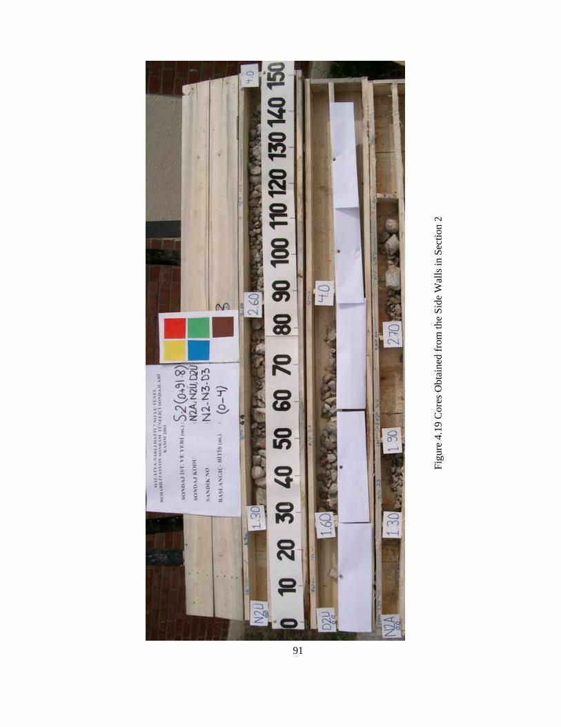
91
Figu
re 4
.19
Cor
es O
btai
ned
from
the
Side
Wal
ls in
Sec
tion
2

92
Figure 4.20 Core Classification and Color Codes (after Unal et al., 2003)
R2
Gravel
Cores
R5
Large Size Particles
R4
R1
Sand
R3
Small Size Particles
R0
Clay

93
Figure 4.21 Coreholes Showing Rock Mass Conditions Surrounding Station 2

94
Dri
lling
St
atio
n
S-3
310
1.0
Sect
ion
Dis
tanc
e fr
om N
arlı
Side
(m)
1/2
Bor
der
85.8
91.8
2
Was
hed
mat
. bet
wee
n 1.
90-2
.70
m; R
3/R
5; %
30
NA
: 1.
30
S-2
S-1
No;
bet
wee
n 1.
6-4.
0 m
; TC
R %
26, w
ater
loss
%80
- No;
bet
wee
n 1.
3-4.
0 m
R3/
R4;
%45
DÜ
:0.8
0D
A:
-N
Ü:
1.30
Voi
d 0.
35 m
wat
er lo
ss %
100;
R3/
(R4+
R5)
+abo
ve 7
m in
j.mat
.%41
V
oid
2.5
m; b
etw
een
1.5-
4 m
TC
R %
8; c
lay
TV:
1.00
(%57
)TB
: 1.
50
The
Thi
ckne
ss o
f the
C
oncr
ete
Lin
ing
(m)
(T
otal
Cor
e R
ecov
ery)
Voi
d 0.
10 m
; bet
wee
n 0.
9-10
m R
3 TC
R=%
57
No;
betw
een
0.9
-4 m
R3
limes
tone
; %49
No;
betw
een
0.8-
2.2
m R
1/R
2; %
60
Voi
d an
d w
ashe
d M
ater
ial B
ehin
d th
e C
oncr
ete
Lin
ing
and
Not
es
-
TV:
0.80
(%78
)TB
: 0.
90D
Ü:
0.80
DA
: 0.
90N
Ü:
070
NA
: -
No;
betw
een
0.9-
4 m
R3
limes
tone
; %49
N
o;be
twee
n 0.
7-4
m R
2/R
3; %
69
No ;
bet
wee
n 1.
5-4.
0 m
. R2/
R3,
wat
er lo
ss %
30-
TV:
1.00
(%60
)TB
: 1.
20D
Ü:
1.60
DA
: 2.
00 (%
?)
No:
bet
wee
n 1-
7 m
R3,
%46
; bet
wee
n 8.
70-8
.90
void
; %10
0 w
ater
loss
Voi
d, b
etw
een
1.2-
4 m
; TC
R %
5; c
lay
No;
bet
wee
n 1.
6-4.
0 m
R3/
R4,
%70
No ;
bet
wee
n 2-
4 m
. R3/
R4;
%54
, wat
er lo
ss %
40 (?
)
TV: R
oof
TB: B
otto
mD
Ü: M
ount
ain
Side
Up
NÜ
: 1.
50N
A:
-
Tab
le 4
.1 T
he In
form
atio
n O
btai
ned
from
Cor
es a
bout
the
Stab
ility
of t
he T
unne
l (1)
DA
: Mou
ntai
n Si
de D
own
TC
R: T
otal
Cor
e R
ecov
ery
(%)
Nar
lı En
tranc
e: K
m 1
55+4
65 m
. N
Ü: C
reek
Sid
e U
pN
A: C
reek
Sid
e D
own
DD
: Mou
ntai
n Si
de W
all
ND
: Cre
ek S
ide
Wal
l

95
Tab
le 4
.1: T
he In
form
atio
n O
btai
ned
from
Cor
es a
bout
the
Stab
ility
of t
he T
unne
l (2)
DA
: Mou
ntai
n Si
de D
own
TC
R: T
otal
Cor
e R
ecov
ery
(%)
Nar
lı En
tranc
e: K
m 1
55+4
65 m
. N
Ü: C
reek
Sid
e U
pN
A: C
reek
Sid
e D
own
DD
: Mou
ntai
n Si
de W
all
ND
: Cre
ek S
ide
Wal
l
TV: R
oof
TB: B
otto
m
DÜ
: Mou
ntai
n Si
de U
p
NÜ
: 1.
00N
A:
0.80
3-4
m u
pper
par
t of t
he tu
nnel
%70
wat
er lo
ss, R
2/R
3; T
CR
%68
No;
betw
een
0.8-
4.0
m R
1/R
2/R
3, T
CR
=%73
TV:
1.00
(%10
0)TB
: 1.
00D
Ü:
0.80
DA
: -
No;
The
last
1 m
dur
ing
drill
ing
TCR
%35
(R3)
Bet
wee
n 1-
2 m
tim
ber/s
and/
clay
;bet
wee
n 2-
4 w
ater
loss
%50
3.6
m u
pper
par
t of t
he tu
nnel
, 0.4
0 m
voi
d an
d %
100
wat
er lo
ss, R
2-N
o;be
twee
n 0.
85-4
.0 m
R2/
R3;
%58
TV:
1.30
(%43
)TB
: 1,
35D
Ü:
1.30
DA
: -
NÜ
: 0.
80N
A:
0.85
- No;
bet
wee
n 0.
8-4.
0 m
R3/
R4;
%49
The
Thi
ckne
ss o
f the
C
oncr
ete
Lin
ing
(m)
(T
otal
Cor
e R
ecov
ery)
No;
bet
wee
n 1.
3-10
m R
2/R
3 %
63W
ashe
d m
at. b
etw
een
1.20
/1.3
5-4.
0 m
. TC
R=
%51
; cla
y / m
arn
No;
bet
wee
n 1.
3-4.
0 m
R3/
R4,
%48
Voi
d an
d w
ashe
d M
ater
ial B
ehin
d th
e C
oncr
ete
Lin
ing
and
Not
es
No;
bet.
1.3-
10 m
. wea
k ro
of, R
1/R
2, u
pper
side
of c
onc.
%45
gen
.%53
Was
hed
mat
.2.8
m, r
emai
ning
ver
y di
sint
egra
ted,
gra
vel,
%35
TV:
1.30
(%69
)TB
: 1.
50
-N
A:
-
S-5
S-4
betw
een
1.5-
4.0
m %
40 w
ater
loss
, TC
R=
%49
, (R
2/R
3)A
t the
end
of t
he d
rillin
g %
60 w
ater
loss
, TC
R=%
47, (
R2/
R3)
betw
een
1.3-
4.0
m w
ater
lost
%30
, (R
1)
DÜ
: 1.
50D
A:
1.50
NÜ
: 1.
30
Dri
lling
St
atio
n
S-6
412
7.42
Sect
ion
Dis
tanc
e fr
om N
arlı
Side
(m)
3/4
Bor
der
104.
15
115.
824

96
Dri
lling
St
atio
n
S-9
818
2.15
Sect
ion
Dis
tanc
e fr
om N
arlı
Side
(m)
4/5
Sını
rı13
9.15
174.
158
No ;
1-2
.5 m
R4;
%72
; 2.5
-4.0
m c
lay;
%63
NA
: 1.
00
S-8
S-7
No,
(btw
. 0.8
-2.1
m R
2/R
3;%
71);
up. 0
.6 m
cla
y; 2
.70-
4 m
R1/
R2
clay
ey- V
oid
2.70
-3.0
m; %
50 w
ater
loss
; TC
R=
%90
DÜ
: 0.
80D
A:
-N
Ü:
1.0
Y+0
.65
No,
bet
wee
n 4-
10 m
%30
wat
er lo
ss, R
2/R
3; T
CR
=%67
No,
R2/
R4;
TC
R=%
47TV
: 1.
50 (%
98)
TB:
1.20
The
Thi
ckne
ss o
f the
C
oncr
ete
Lin
ing
(m)
(T
otal
Cor
e R
ecov
ery)
No;
Sou
nd ro
of
No;
wat
er lo
ss b
ehin
d th
e co
ncre
te (%
50-1
00),
(R3/
R4/
R5)
Voi
d is
ver
y lo
w; R
2/R
3
Voi
d an
d w
ashe
d M
ater
ial B
ehin
d th
e C
oncr
ete
Lin
ing
and
Not
es
-
TV:
1.30
(%86
)TB
: 1.
00D
Ü:
1.00
DA
: 0.
60N
Ü:
1.05
NA
: -
Voi
d, 1
.20
m u
pper
of t
he c
oncr
ete
is R
1/R
2; T
CR
%56
; with
cla
yey
No ;
betw
een
1.05
-4.0
m is
R2/
R3/
R4;
TC
R %
39
Voi
d be
twee
n 2.
5-3
m a
nd %
100
wat
er lo
ss; b
etw
een
1.5-
2.0
m %
72-
TV:
1.00
(%10
0)TB
: 1.
50D
Ü:
0.85
DA
: 0.
90
No;
R2/
R3/
R4;
%51
;bet
wee
n 7-
10 m
%40
wat
er lo
ssN
o; 0
.1 m
cla
y; b
etw
een
1.60
-4 m
R2/
R3;
%65
No;
betw
een
0.8-
4 m
R3/
R4/
R5;
%54
No;
betw
een
0.9-
4 m
R2/
R3;
%61
TV: R
oof
TB: B
otto
mD
Ü: M
ount
ain
Side
Up
NÜ
: 1.
50 (%
?)N
A:
-
Tab
le 4
.1: T
he In
form
atio
n O
btai
ned
from
Cor
es a
bout
the
Stab
ility
of t
he T
unne
l (3)
DA
: Mou
ntai
n Si
de D
own
TC
R: T
otal
Cor
e R
ecov
ery
(%)
Nar
lı En
tranc
e: K
m 1
55+4
65 m
. N
Ü: C
reek
Sid
e U
pN
A: C
reek
Sid
e D
own
DD
: Mou
ntai
n Si
de W
all
ND
: Cre
ek S
ide
Wal
l

97
ND
: 0.3
0
Dri
lling
St
atio
n
ST-E
xtra
10
Sect
ion
Dis
tanc
e fr
om N
arlı
Side
(m)
S-10
btw
. 0.3
-1.5
m R
2/R
3; %
60; b
tw. 1
.5-4
.0 m
R2/
R3
with
inje
ctio
n; %
65
919
2.9
No;
btw
. 1.0
-4.0
m R
2/R
3/R
4/R
5; %
57; 4
m S
urr.
%50
wat
er lo
ssN
o;bt
w. 1
.20-
2.5
m R
2/R
3 cl
ayey
%46
; upp
er p
art R
5; %
66
DA
: -
NÜ
: 1.
00N
A:
1.20
-D
Ü:
1.00
TB: B
otto
mD
Ü: M
ount
ain
Side
UpTab
le 4
.1 T
he In
form
atio
n O
btai
ned
from
Cor
es a
bout
the
Stab
ility
of t
he T
unne
l (4)
The
Thi
ckne
ss o
f the
C
oncr
ete
Lin
ing
(m)
(T
otal
Cor
e R
ecov
ery)
4.20
-5 m
voi
d an
d %
100
wat
er lo
ss; 1
.3-4
.2 m
R4;
%32
. was
hed
mat
.
No;
bet
wee
n 1.
5-3.
0 m
mat
eria
l with
sand
(R1)
; %36
No;
betw
een
1.0-
4.0
m R
2/R
3/R
4/R
5; %
58
Voi
d an
d w
ashe
d M
ater
ial B
ehin
d th
e C
oncr
ete
Lin
ing
and
Not
es
TV:
1.30
(%85
)
TB:
1.50
DA
: Mou
ntai
n Si
de D
own
TC
R: T
otal
Cor
e R
ecov
ery
(%)
Nar
lı En
tranc
e: K
m 1
55+4
65 m
. N
Ü: C
reek
Sid
e U
pN
A: C
reek
Sid
e D
own
DD
: Mou
ntai
n Si
de W
all
ND
: Cre
ek S
ide
Wal
l
TV: R
oof

98
4.7 Surface and Underground Water Reducing the Tunnel Stability
4.7.1 History
The reports prepared earlier by TCDD engineers before the beginning of
the rehabilitation work of the tunnel indicates the existence of a serious water
problem in the tunnel.
The water-table is about 8-14 meters below the tunnel floor and it is
located at the top of an alluvial strata. It is probable that this water-table on alluvial
strata triggers the tunnel to be displaced from the mountain side towards the creek
side. On the other hand, the water precipitation leaking into the rock-mass around
the tunnel has always given rise to stability problems. The water always weakens the
disintegrated rock-mass and exerts pressure on concrete-lining thus reduce the
stability.
During the geological studies carried out before the cleaning of the
collapse, it was comprehended that the tunnel had been driven in paleo-landslide of
melange type. Consequently, it is always expected to have underground water
inflow at different sections of the tunnel, especially from the mountain side. During
investigations it was also seen that a water drainage gallery at a distance of 40 m to
the tunnel on the mountain side had been opened parallel to No:7 Tunnel aimed at
relieving the effect of water. Nonetheless, this precaution worked partially, and the
tunnel continued to deform together with the drainage gallery through the years.
4.7.2 Work Performed Inside the Tunnel
As stated in section 4.7.1 in order to reduce the effect of water to a
minimum inside the tunnel, a drainage system was accomplished to reduce the water
pressure on concrete walls of the tunnel, to prevent the effect of water on poor rock-
mass and reduce the swelling effect of water on smectite type of clay.

99
Along the both sides of the tunnel drainage channels were constructed
inside the invert at the floor. The drainage pipes having a diameter of 200 mm and
surrounded by geotextile were inserted along the tunnel bottom as demonstrated in
Figure 4.22.
Figure 4.22 Water Drainage Ditches before and after Inserting the Tunnel Type Drainage Pipes
Along the mountain side of the tunnel, galvanized and perforated drainage
pipes having a diameter of 75 mm and length of 10 m and spacing of 5.0 meters
were inserted into the tunnel wall with a staggered pattern as shown in Figure 4.23
and 4.24. The location of the upper holes of the drainage pipes were 2.0 meters and
the lower holes were 0.5 m from tunnel bottom.
Figure 4.23 Perforated Drainage Pipes at the Walls of the Tunnel

100
dsdf
Figure 4.24 The Drainage System Along the Tunnel
At the creek side of the tunnel, in Sections 2, 3, 3/4 border, 4 and 8,
drainage pipes having a length of 3.0 meters were inserted.
4.7.3 Work Performed on the Surface
On the earth surface above the tunnel, a total of 11 drainage wells, spaced
15 meters to the each other and having a diameter of 300 mm were sank vertically
from the surface to the drainage gallery, in order to collect the surface and
underground water inside of the drainage gallery as demonstrated in Figure 4.25.
10 m

101
Figure 4.25 The Drainage System above the Tunnel
During rehabilitation work the earlier collapse in the drainage gallery was
cleaned up. Drainage pipes having spacing of 1.0 meter, a diameter of 100 mm, and
a length of 0.50 meter were inserted into the walls as shown in Figure 4.26.
Figure 4.26 The Condition of Drainage Gallery after Rehabilitation
DRAINAGE WELL
Ø 300 mm
DRAINAGE GALLERY
TUNNEL
150 m
Ø 100 PVC PIPES
cm cm cmcm

102
4.8 Unstable Sections Requiring Urgent Repair
Section 13 (The section between km 155-686.65 and 697.65)
This section was shotcreted and supported by 17 temporary steel-arches to
protect existing stone lining. The condition of the old tunnel support (walls made up
of) were in good condition.
Section 11 (The sections between km 155+666.65 and 669.95)
In this section, reinforced concrete-lining was completed and the steel-
frame for making concrete-lining was removed after providing the stability of the
adjacent sections.
Section 10 (The section between km 155+660.65 and 666.65)
There was a 0.60 m cavity between the steel-frame, used for making
concrete-lining, and the tunnel’s stone wall and the existing roof was unstable.
Hence, by applying a grout injection to the roof, a concrete arch having a thickness
of 3.0-4.0 m was formed
Section 8 (The section, 25 meters between km 155+631.15 and 655.15)
The concrete sleeves inserted on the original tunnel walls were broken.
Moreover, axial cracks were observed on the wall at the mountain side. During the
rehabilitation work, the suspended and peeled-off concrete sleeves were broken and
dropped down by workers.

103
Section 7 (The section, 5.5 meters between km 155+625.65 and 631.15)
This is the section where a relatively small roof-fall occurred earlier. The
concrete-lining between the mountain side and the roof arch was broken. Also, the
concrete-lining in the roof was broken. During the rehabilitation works 10 new steel-
sets were installed in this section and shotcreted and the existing cavities in the roof
were back-filled by grouting. In addition, the concrete sleeve that was peeled off at
the creek side was broken and dropped down.
Section 5/6 Boundary
(The 2 meters section between km 155+614.65 and 616.65)
There were some peeled-off rocks in the roof. The old steel-sets could be
visibly seen in the wall at the mountain side. During the rehabilitation work the
concrete sleeves on the creek side were poured, and coated by shotcrete.
Section 2 (The section 12 meters between km 155+550.80 and 562.80)
The sleeved concrete-lining on the creek side was fractured and suspended.
In addition, there were deep cracks especially on the mountain side and arching
towards the inner parts. During the rehabilitation works the concrete sleeves were
peeled off and dropped down. Afterwards, 0.20 m thick shotcrete was applied over
the steel- arches. Typical photographs showing the tunnel Regions requiring
immediate repair and support are shown in Figures 4.27, 28, 29 and 30.

104
Figure 4.27 The Condition of Section 7 before the Rehabilitation of the Tunnel
Figure 4.28 The Condition of Section 7 after the Rehabilitation of the Tunnel
MOUNTAIN SIDE

105
Figure 4.29 Examples of Spalling at the Tunnel before Rehabilitation Work
Figure 4.30 The Condition of the Sections 7 and 8 at the Mountain Side after Rehabilitation works
In Sections 2, 3, 4 (last 5 m to the Section 5 border), 7, 8, 10 and 12 NPI-
160 steel-sets were installed with an interval of 0.50 m. Steel-sets were connected to
each other by using I-120 steel profiles. The legs of the steel-sets were nailed to the
concrete-lining by using 3 m rebars. This application is shown in Figure 4.31.
MOUNTAIN SIDE AT

106
Figure 4.31 Nailing of the Steel-Sets by Using 3 m bolts
After injection of grout having a thickness of 8.0 m at the arch part of
Sections 2, 3, 7 and 10, these sections were reinforced with ribbed or threaded bolts
as shown in Figure 4.32. However, the thickness of the injection was 5.0 meters at
the border of 3 and 4. And also, the quantities of the applied injection in different
sections are given in Table 4.2.
Figure 4.32 Concrete Injection Covering the Roof
3 m
8 m Ø 32 BOLTS
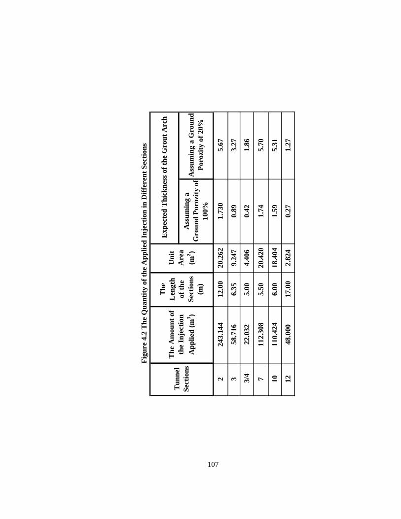
107
110.
424
48.0
00
2 3 3/4 7 10 12
243.
144
58.7
16
18.4
04
2.82
4
6.00
17.0
0
5.00
5.50
22.0
32
112.
308
5.31
1.27
1.73
0
0.89
0.42
1.74
1.59
0.27
5.67
3.27
1.86
5.70
Uni
t A
rea
(m2 )
The
L
engt
h of
the
Sect
ions
(m
)
20.2
62
9.24
7
4.40
6
20.4
20
12.0
0
6.35
Figu
re 4
.2 T
he Q
uant
ity o
f the
App
lied
Inje
ctio
n in
Diff
eren
t Sec
tions
The
Am
ount
of
the
Inje
ctio
n A
pplie
d (m
3 )
Tun
nel
Sect
ions
Exp
ecte
d T
hick
ness
of t
he G
rout
Arc
h
Ass
umin
g a
Gro
und
Poro
zity
of
100%
Ass
umin
g a
Gro
und
Poro
zity
of 2
0%

108
CHAPTER 5
ROCK REINFORCEMENT IN NO: 7 RAILROAD TUNNEL
5.1 General
During rehabilitation work, the collapses were cleaned, adequate span was
provided for normal tunnel traffic, voids were tried to be filled with grout injection
and repair of the support was completed. Consequently, the tunnel was put into
service on August 3, 2003.
After completion of the rehabilitation work, a total of fifty cores were
drilled inside the tunnel in order to assess the rock mass conditions. In addition, to
decide on the short-term behaviour of the tunnel and to evaluate the stability,
deformation measurements were carried out.
Based on existing rock mass conditions and the numerical studies carried
out using Phase 2D software, the lowest safety factor in the roof was found as 1.20
(Unal, 2003). Consequently, Self Drilling Anchors (SDA) and ground injection were
decided to be carried out.
5.2 General Remarks about Rock Reinforcement
Tunnel Sections 2, 3, 4, 5, 6 and 8, located between km 155+548 and km
155+658 (Figure 5.1), have been reinforced systematically by using MAI type self-
drilling anchors (SDA) and ground injection was applied in these sections.

109
5.3 Reinforced Sections (at the Walls of the Tunnel)
Before application of the bolting system, the tunnel has been divided into
different support sections according to the bolting pattern used as A1, B and A2 as
shown in Figure 5.1. The bolt length used in the tunnel was 6.0 meters.
Section B was the most problematic section of the tunnel affected by
excessive deformation and displaced towards the creek side as much as 1.70 m. This
section taking place between km 155+563-610 was reinforced with self-drilling
anchors (SDA) as shown pattern in Figure 5.2. The other two sections, namely, A1
and A2 have been reinforced by the same type of bolts having different pattern as
shown in Figure 5.3.
110
Figure 5.1 SDA Applied Sections for the Tunnel Walls
Creek Side
Malatya
km 155+697.65
km 155+686.65
km 155+669.65
km 155+666.65
km 155+660.65
km 155+655.15
km 155+631.15
km 155+625.65
km 155+614.65
km 155+604.15
km 155+569.15
km 155+562.8
km 155+550.8
Entrance km 155+465 0.0 m
85.8 m
97.8 m
104.15 m
139.15 m
150 m
190 m
195.65 m
202 m205 m
221.65 m
239 m
Narlı
160.65 m
166.15 m
Displaced Section-4
12 13
11 10 9
87
65
32
1
Mountain Side
193 m km 155+658
145 m km 155+610
97.8 m km 155+563
83 m km 155+548
Supported Section (A2)
by MAI Bolts 48 m
Supported Section (B)
by MAI Bolts 47 m
Supported Section (A1)
by MAI Bolts 15 m
14 km 155+822365 m

111
Figu
re 5
.2 M
ai B
olt (
SDA
) Ins
talla
tion
Patte
rn fo
r Sec
tion
B
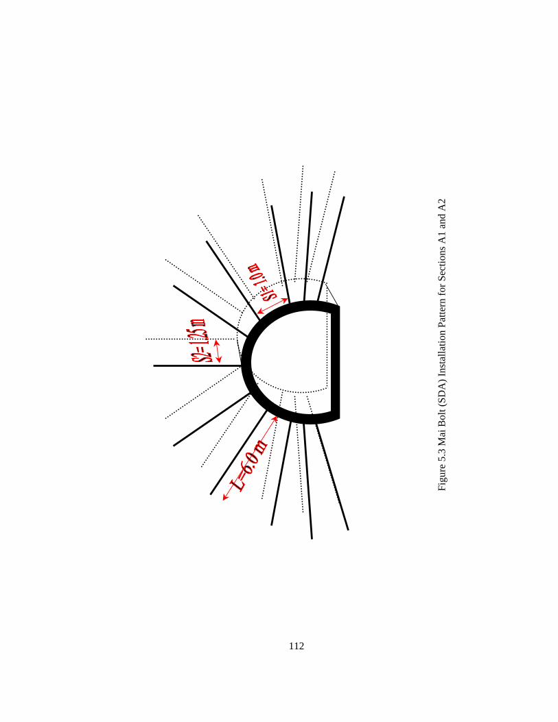
112
Figu
re 5
.3 M
ai B
olt (
SDA
) Ins
talla
tion
Patte
rn fo
r Sec
tions
A1
and
A2

113
5.4 Stability of the Floor
After examining the cores drilled in different sections of the tunnel, the
necessity to improve the stability of the tunnel bottom appeared especially at
Sections 2, 3, 4 and 9 owing to the voids under the bottom of the tunnel.
There were neither concrete and invert nor support in the tunnel bottom at
locations between km 155+545-631 and km 155+631-661 before the MAI bolt
application has been started. There were just ballast, concrete invert having a
thickness of 0.15 m and other fittings under the rail as shown in Figure 5.4. The
suggested rock reinforcement application for the tunnel floor is also shown in Figure
5.5.
Figure 5.4 Rock Reinforcement Application for the Floor
Typical rock reinforcement work carried out in No: 7 Tunnel are shown in
Figures, 5.6, 5,7 and 5,8.
6 meters in length
6 meters in length 6 meters in length
RailSleeperBallastSheet Iron PlateConcrete+Mesh

114
Figure 5.5 The Mai Bolt SDA Applied Sections for the Tunnel Floor
Creek Side
Malatya
km 155+697.65
km 155+686.65
km 155+669.65
km 155+666.65
km 155+660.65
km 155+655.15
km 155+631.15
km 155+625.65
km 155+614.65
km 155+604.15
km 155+569.15
km 155+562.8
km 155+550.8
Entrance km 155+465 0.0 m
85.8 m
97.8 m
104.15 m
139.15 m
150 m
190 m
195.65 m
202 m205 m
221.65 m
239 m
Narlı
160.65 m
166.15 m
Displaced Section-4
12 13
11 10 9
87
65
32
1
Mountain Side
80.0 m km 155+545
29.5 m
80.65 m
14 km 155+822365 m

115
Figure 5.7 Coupling and Drill Bits Used for MAI Self Drilling Installation
Figure 5.6 Jumbo Used in No: 7 Tunnel for Installation of MAI SDA

116
(a) (b)
(c)
Figure 5.8 (a) Grout Injection, (b) Grout Coming Out of the Drill-Hole
(c) Rock Bolt Plate

117
5.5 Self Drilling Anchorage (MAI Bolt)
MAI Self Drilling Anchoring System (SDA) is a fully threaded steel bar
which can be drilled and grouted into loose or collapsing soils without the use of a
casing. The bar, or SDA, features a hollow bore for flushing, or simultaneous
drilling and grouting and has a left-hand rope thread for connection to standard drill
tooling.
The system can be installed in a variety of different soils and ground
conditions ranging from sand and gravel to inconsistent fill, boulders, rubble and
weathered rock as well as through footings and base slabs.
Self Drilling Anchors are installed with air driven or hydraulic rotary
percussion drilling equipment, using a borehole flush medium suitable for the
specific ground conditions.
There are three types of borehole flush: i) water flush for long boreholes in
dense sand, gravel formations or rock conditions, for a better transportation of large
cuttings and cooling of the drill bit; This procedure has been applied in Malatya-
Narlı No: 7 Railroad Tunnel ii) air flush for short boreholes in soft soil, such as
chalk and clay, where water spillage is to be avoided; iii) simultaneous drilling and
grouting for all lengths of boreholes in all unconsolidated soil conditions.
Underground applications of the Mai Bolts include:
i. Radial anchoring for stabilization of tunnel circumference during excavation
ii. As forepoles, spiles or as an umbrella for advance protection of the excavation
iii. As roof piles for reaction load of steel support arches iv. Slope stabilization of a tunnel portal
The system has six main components: bar, NG-coupler, hexagonal nut,
bearing plate, drill bit and grouting MAI Pump as shown in Figure 5.9.
118
The MAI bar is manufactured based on API standard heavy walling steel
tubing, cold rolled to form a rope thread profile (Atlas Copco Catalog, 2003). The
rolling process refines the grain structure of the steel, increasing the yield strength,
producing a durable drill rod suitable for a range of applications. The anchor bar’s
full-length left-hand rope thread gives the flexibility to adjust the bar length to the
actual requirement. So, it is produced in 12 m lengths and then cut to size depending
on requirements.
The NG-coupler enables direct end to end bearing between each rod,
reducing energy loss and ensuring maximum percussive energy at the drill bit. It has
a thread arrangement in which the top half of the thread is rotated against that of the
lower, providing a centre stop for each bar. All couplers exceed the ultimate strength
of the bar by 20%.
The hexagonal nut, which is machined with right-angled edges on both
ends from high precision steel, is tempered to meet any stringent specifications and
the daily operations of underground works. All nuts exceed the ultimate strength of
the bar by 20%.
The bearing plate is a formed steel plate with a centre hole, allowing
articulation of seven degrees in all directions.
The MAI Pump had a flexible adjustment of the water/cement ratio
depending on the geology and positioning of the bolt which ensured that grout
wastage could be reduced to a minimum (Figure 5.10).
Technical specifications of MAI SDA and MAI Pump used in Malatya-
Narlı No: 7 Tunnel are shown in Table 5.1 and 5.2 respectively.
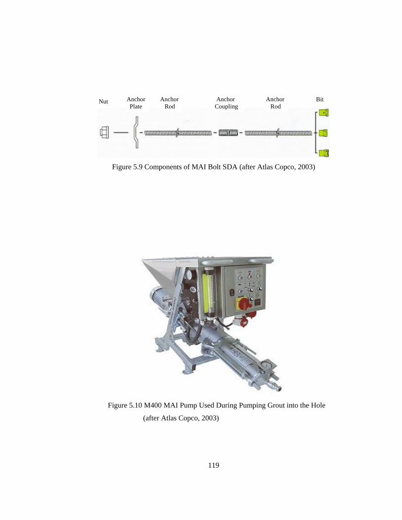
119
Figure 5.9 Components of MAI Bolt SDA (after Atlas Copco, 2003)
Figure 5.10 M400 MAI Pump Used During Pumping Grout into the Hole
(after Atlas Copco, 2003)
Nut Anchor Plate
Anchor Rod
Anchor Coupling
Anchor Rod
Bit

120
Table 5.1 Technical Specifications of Mai SDA
Table 5.2 Technical Specifications of Mai Pump
Unit R32N Size Unit R32Nmm 32 Diameter mm 42mm 18.5 Length mm 160mm 29.1 Weight kg 0.85
mm2 396kN 280kN 230
MPa 720 Size Unit R32N
MPa 560 Key Size mm 46kg 3.4 Length mm 45m 3.0 Weight kg 0.35
Unit R32N Typemm 200x200 EXmm 10mm 35kg 3.0Weight
SizeDRILL BIT
R32NR32/51
Technical detailsANCHOR ROD
Ultimate load capacity
Hole-diameter
Yield load capacity
Ave. tensile strength Rm
Outside dia.Ave. internal dia.Eff. external dia.Ave. eff.cross-sect. area
COUPLING
NUT
Ave. yield strength Rp 0,2
PLATE
ThicknessDimension
WeightLength
Unit m400l/h 400-2400m 60
bar 60mm 1800mm 790mm 1050kg 235V 400A 13.7
bar 4-70.4-0.7
AmperageInjection pressureWater/cement ratio
MAI PUMPTechnical detailsDelivery rateDelivery distanceDelivery pressureTotal lengthTotal widthTotal heightTotal weightElectric supply

121
CHAPTER 6
FIELD MEASUREMENTS IN NO:7 MALATYA-NARLI RAILROAD TUNNEL
6.1 Introduction
In this chapter, details associated with convergence measurements will be
given. In addition, information on convergence recorder “DISTOMETER”,
locations of convergence stations, and installations of stations will be explained.
Finally, the results of convergence measurements will be presented in detail
considering the relation between “convergence” vs. “time”.
6.2 Convergence Measurement
In order to determine the short term behaviour of the tunnel and to evaluate
the stability of the tunnel before rock reinforcement applications, a series of
measurements were carried out at 15 deformation stations. These stations were
installed through the tunnel. In each station, deformation between roof and floor,
and two walls of the tunnel were measured.

122
6.3 Distometer
The Kern Distometer ISETH (a development by members of the Institute
for Road and Rock Engineering of the Federal Institute of Technology, Zurich,
Switzerland) is a mechanical precision instrument determining the differences in
distances with the aid of invar wires. The system combines in one single instrument,
a means for adjustment of tension force with a means for measurement of length
both necessary or measuring with invar wires.
The required tension force is produced by a precision steel spring whose
extension is measured by a dial gauge. The required tensile force of 8 kgf (78.85 N)
is reached as soon as the dial gauge indicates the corresponding elongation which
can be checked by a standard weight.
By means of a shiftable pull rod the Distometer can be varied in length
between its connections at the setting bolt and at the measuring wire. Therefore, a
strechted wire connected with the Distometer is subject to a varying tension force.
The length of the Distometer necessary to maintain a tensional force of 8 kp yields
the measured distance-except for an unimportant constant. A variation in the length
of the observed line is thus indicated by a variation in length of the Distometer
which is equal to the positional variation of the pull rod displayed by a dial gauge.
The difference between two measurements values therefore represents the variation
in length of the measured line.
A calibration gauge for monitoring the length of the Distometer and a
standard weight of 8 kg for calibrating the dial gauge for measuring spring
extension, are part of the Distometer equipment. A general view of Distometer used
during convergence measurements is demonstrated in Figure 6.1.
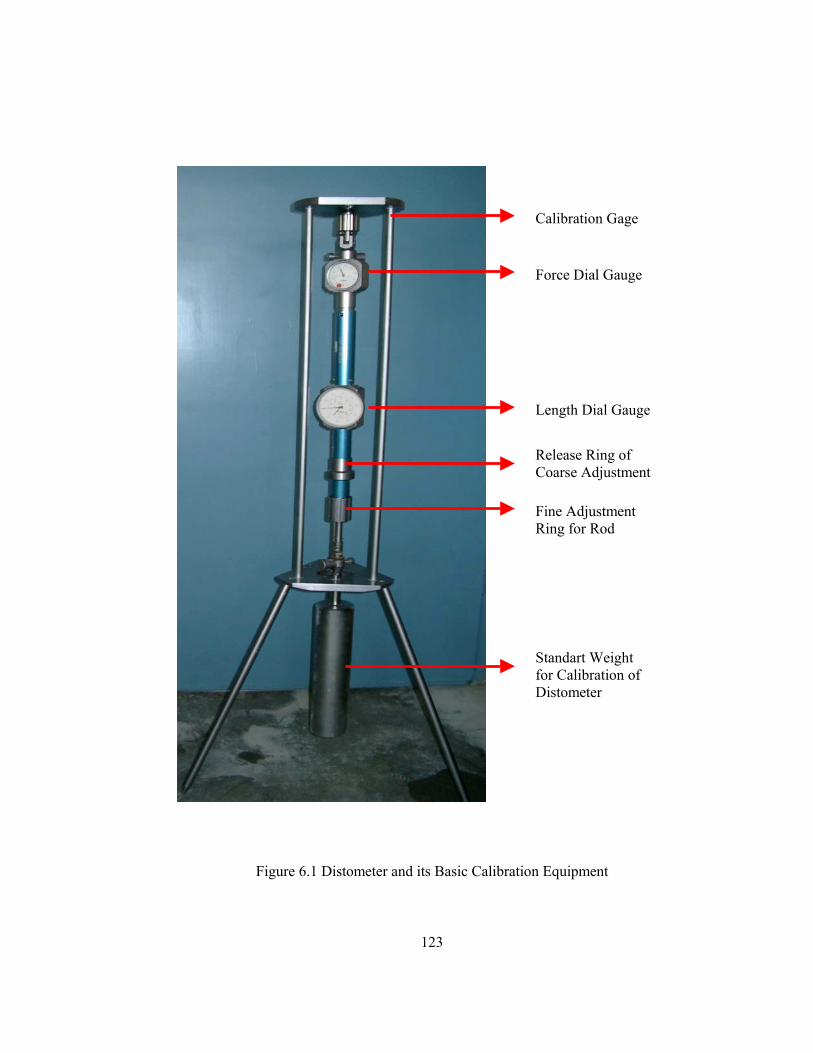
123
Figure 6.1 Distometer and its Basic Calibration Equipment
Force Dial Gauge
Length Dial Gauge
Calibration Gage
Release Ring of Coarse Adjustment
Fine Adjustment Ring for Rod
Standart Weight for Calibration of Distometer

124
6.4 Locations of Convergence Stations
During field studies a total of 15 deformation stations were installed in the
tunnel. 11 of these stations (Y1, Y2,.....Y10) were located in the deformed part, and
5 of them (Y11, Y12,......,Y15) were located in the non-deformed part of the tunnel.
A general view of a convergence station is shown in Figure 6.2. The locations of the
stations through the tunnel are shown in Figure 6.3.
Figure 6.2 General View of a Convergence Station where Horizontal and Vertical Displacements are Measured
6.5 Installation of Convergence Stations
At each convergence station four steel rebars were fixed into the rock-mass
after drilling holes in the both walls, the roof and the bottom, as illustrated in Figure
6.4.

125
Figure 6.3 Locations of the Stations Through the Tunnel
Y1
Station 9
Station 5
km 155+465
1
Displaced Section
MOUNTAINSIDE
CREEK SIDE
Station 15
14 km 155+822
Stable Zones
Station 1
D1D1
Y1
Misaligned Z
ones
D: Vertical Y: Horizontal

126
Figure 6.4 Locations of the Rebars Used as Measuring Points
Each station consisted of 4 rebars. The rebars fixed at the mountain side,
between Stations 2 and 8 were 8 m in length. Whereas the remaining rebars were
0.50 m. The reason why 8.0 meters long rebars were fixed at the mountain side was
because of providing a relatively stationary (not moving) anchorage inside the rock
mass at the mountain side moving towards the creek side.
The convergence stations were installed by the help of the members of
TCDD and contractor firm, Tokacar İnşaat.
Horizontally Installed Rebars
Vertically Installed Rebars
Vertically Installed Rebars
Direction of Movement

127
6.6 Frequency of Convergence Measurements
Convergence measurements were taken as three times between the dates
January 22 and April 30, 2004. Consequently, the movement occuring due to
displacement of the tunnel from the mountain side towards the creek side was tried
to be determined. The measuring period was about 100 days. The measurement
could not be taken after this period because rock reinforcement was started in the
tunnel.
Figure 6.5 Convergence Measurement at a Station
“Convergence” versus “Time” relationships were plotted for each station
by using the data obtained from convergence measurements. Considering the total
convergence occured in the tunnel maximum vertical convergence was 4.78 mm at
Station 2 and maximum horizontal movement was 8.78 mm at Station 4. At this
stage, it was concluded that rehabilitation work had not been adequate enough to
provide stability of the tunnel and additional support would be required.
Interpretations of the other measurements are presented in the next section.
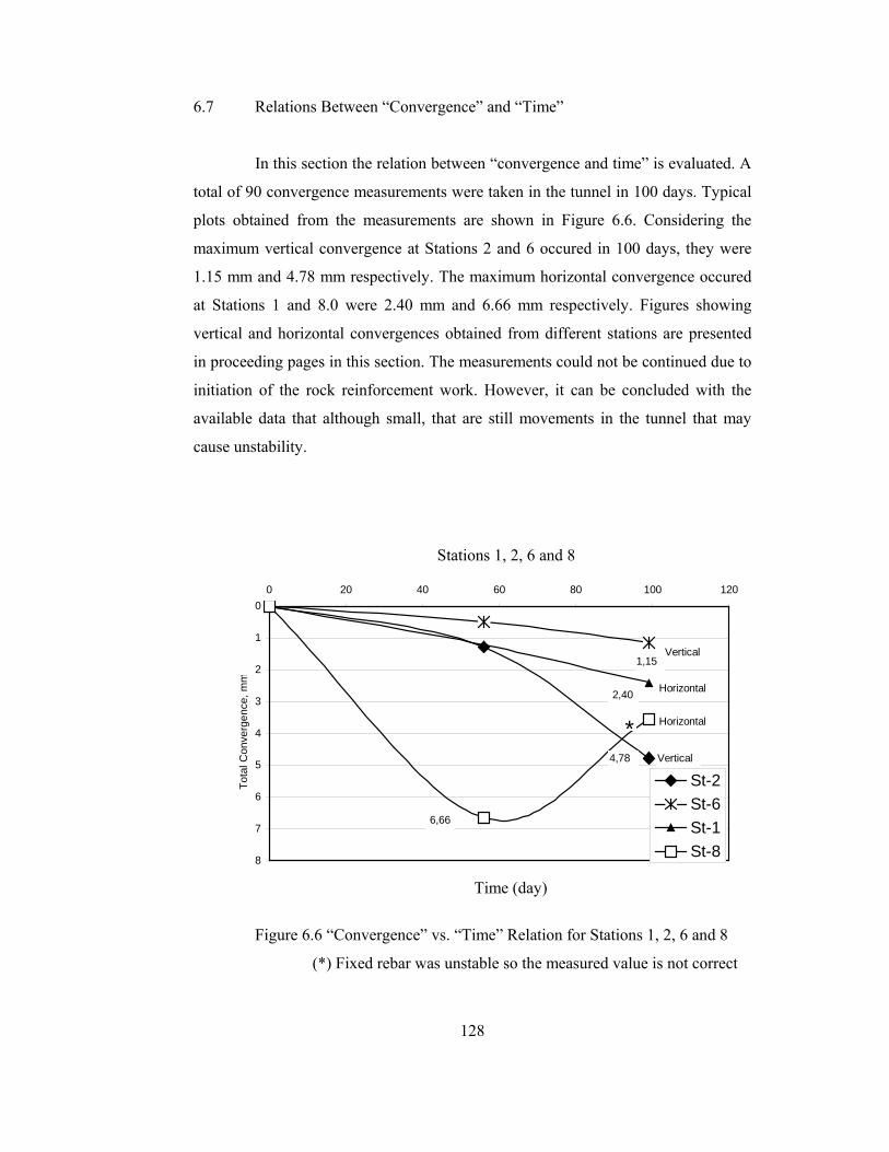
128
6.7 Relations Between “Convergence” and “Time”
In this section the relation between “convergence and time” is evaluated. A
total of 90 convergence measurements were taken in the tunnel in 100 days. Typical
plots obtained from the measurements are shown in Figure 6.6. Considering the
maximum vertical convergence at Stations 2 and 6 occured in 100 days, they were
1.15 mm and 4.78 mm respectively. The maximum horizontal convergence occured
at Stations 1 and 8.0 were 2.40 mm and 6.66 mm respectively. Figures showing
vertical and horizontal convergences obtained from different stations are presented
in proceeding pages in this section. The measurements could not be continued due to
initiation of the rock reinforcement work. However, it can be concluded with the
available data that although small, that are still movements in the tunnel that may
cause unstability.
Figure 6.6 “Convergence” vs. “Time” Relation for Stations 1, 2, 6 and 8
(*) Fixed rebar was unstable so the measured value is not correct
0
1
2
3
4
5
6
7
8
0 20 40 60 80 100 120
Tota
l Con
verg
ence
, mm
St-2St-6St-1St-8
Horizontal
Horizontal
Vertical
Vertical
6,66
2,40
4,78
1,15
*
Stations 1, 2, 6 and 8
Time (day)

129
The convergence results obtained from Stations 9, 10, 11, 12 and 13,
installed in tunnel Sections 8, 9, 10 and 12, are less than 1.0 mm (see Table 6.1 and
Figures 6.9 to 6.12). Although more data is needed to be able to interpret the results,
it can be concluded that 167 meters of the tunnel is stable (including Section 14) as
seen in Figure 6.3.
Due to the compression, closure was observed in the tunnel at Stations 4
and 5 installed in Section 4. The maximum horizontal movement was 8.78 mm at
Station 4 probably due to compressive stresses acting from the mountain side.
Consequently, it was concluded that there were still movement in Section 4.
Sections 2 and 3 were the most problematic sections in the tunnel in terms
of water effect, especially in rainy seasons. At Station 1, installed in Section 2
horizontal closure and vertical dilation were observed as shown in Figure 6.7.
Figure 6.7 Horizontal Closure and Vertical Dilation in Section 2
The last kind of movement of the tunnel occurred at Stations 2, 3, 6, 7 and
8 installed in Sections 3, 4, 5, 6 and 7 respectively. Especially Sections 3 and 4,
which are approximately 40 m in length, have a tendency of displacement from
mountain side towards creek side. Eight meters long measuring pins or rebars were
22

130
fixed in the rock-mass at the mountain side between Stations 2 and 8, in order to
obtain a relatively stable point and observe the movement of the creek side wall.
Based on the measurements in these sections, it can be concluded that the tunnel has
a tendency of shifting from mountain side towards creek side as shown in Figure
6.8. Consequently, a reinforcement application is necessary to stabilize the tunnel.
Figure 6.8 The Behaviour of Tunnel Sections 3 and 4
It is very difficult to interpret the results of convergence because only three
measurements (including, “0”) had been taken in 100 days and then, the rock
reinforcement process was started and caused measurements to be stopped.
However, considering the horizontal and vertical convergences larger than 1.0 mm
(please see, Table 6.1 and Figures 6.9, 6.10, 6.11 and 6.12). It can be concluded that:
i. In tunnel Sections 2, 3, 4 and 7 (Stations 1, 2, 4, 5 and 8) there were
both horizontal and vertical movements.
ii. In tunnel Sections 6 (Station 7) there was horizontal movement only.
iii. These results show that Sections 2 to 9 No: 7 Tunnel are still instable
and requires rock reinforcement.
33
44
Mountain Side
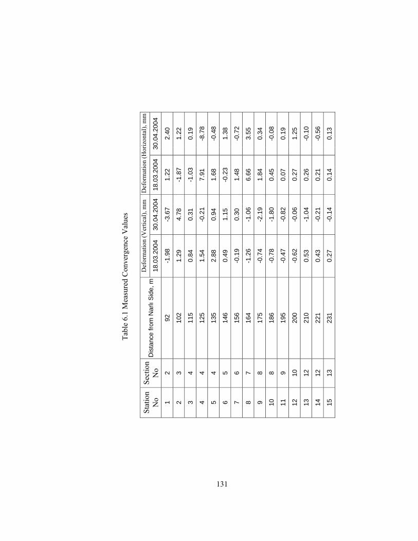
131
30
.04.
2004
2.40
1.22
0.19
-8.7
8
-0.4
8
1.38
-0.7
2
3.55
0.34
-0.0
8
0.19
1.25
-0.1
0
-0.5
6
0.13
Def
orm
atio
n (H
oriz
onta
l), m
m
18.0
3.20
04
1.22
-1.8
7
-1.0
3
7.91
1.68
-0.2
3
1.48
6.66
1.84
0.45
0.07
0.27
0.26
0.21
0.14
30.0
4.20
04
-3.6
7
4.78
0.31
-0.2
1
0.94
1.15
0.30
-1.0
6
-2.1
9
-1.8
0
-0.8
2
-0.0
6
-1.0
4
-0.2
1
-0.1
4
Def
orm
atio
n (V
ertic
al),
mm
18.0
3.20
04
-1.9
8
1.29
0.84
1.54
2.88
0.49
-0.1
9
-1.2
6
-0.7
4
-0.7
8
-0.4
7
-0.6
2
0.53
0.43
0.27
Tabl
e 6.
1 M
easu
red
Con
verg
ence
Val
ues
Dis
tanc
e fro
m N
arlı
Sid
e, m
92
102
115
125
135
146
156
164
175
186
195
200
210
221
231
Sect
ion
No 2 3 4 4 4 5 6 7 8 8 9 10
12
12
13
Stat
ion
No 1 2 3 4 5 6 7 8 9 10
11
12
13
14
15
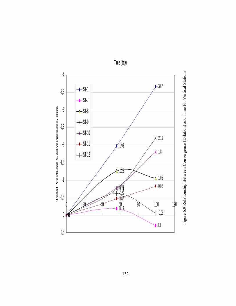
132
0
-1,98
-3,67
0-0,19
0,3
0
-1,26-1,06
0
-0,74
-2,19
0
-0,78
-1,8
0
-0,47
-0,82
0
-0,62
-0,06
-4
-3,5
-3
-2,5
-2
-1,5
-1
-0,5
0
0,5
0 20 40 60 80 100 120
Time (day)T
otal V
ertical C
on
vergen
ces, m
m
ST-1
ST-7
ST-8
ST-9
ST-10
ST-11
ST-12
Figu
re 6
.9 R
elat
ions
hip
Bet
wee
n C
onve
rgen
ce (D
ilatio
n) a
nd T
ime
for V
ertic
al S
tatio
ns

133
0
1,29
4,78
0
0,84
0,310
1,54
-0,210
2,88
0,94
0
0,53
-1,04
00,27
-0,14
-2
-1
0
1
2
3
4
5
6
0 20 40 60 80 100 120
Time (day)T
ota
l V
ertica
l C
on
verg
en
ce, m
m
ST-2
ST-3
ST-4
ST-5
ST-6
ST-13
ST-14
ST-15 Figu
re 6
.10
Rel
atio
nshi
p B
etw
een
Con
verg
ence
(Clo
sure
) and
Tim
e fo
r Ver
tical
Sta
tions

134
0
1,22
2,4
0
1,48
-0,72
0
6,66
3,55
0
1,84
0,340
0,45-0,080 0,07 0,190 0,27
1,25
-2
-1
0
1
2
3
4
5
6
7
8
0 20 40 60 80 100 120
Time (day)T
otal H
orizon
ta
l V
erical C
on
vergen
ce, m
m
ST-1
ST-7
ST-8
ST-9
ST-10
ST-11
ST-12
Figu
re 6
.11
Rel
atio
nshi
p B
etw
een
Con
verg
ence
(Clo
sure
) and
Tim
e fo
r Hor
izon
tal S
tatio
ns

135
0
-1,87
1,22
0-1,03
0,190
7,91
-8,78
0
1,68
-0,480 -0,23
1,38
0 0,26 -0,10 0,21-0,56
0 0,14 0,13
-10
-8
-6
-4
-2
0
2
4
6
8
10
0 20 40 60 80 100 120
Time (day)T
ota
l H
orizo
nta
l C
on
verg
en
ce, m
m
ST-2ST-3ST-4ST-5ST-6ST-13ST-14ST-15
Figu
re 6
.12
Rel
atio
nshi
p B
etw
een
Con
verg
ence
(Dila
tion)
and
Tim
e fo
r Hor
izon
tal S
tatio
ns

136
CHAPTER 7
CONCLUSIONS AND RECOMMENDATIONS
7.1 Conclusions
Based on the studies carried out within the scope of this M.Sc. Thesis, the
following conclusions can be drawn:
1) The extensive literature survey carried out in this study identifies the
problems of the excavated tunnels and typical excavation work
necessary for unstable tunnels.
2) The No: 7 tunnel located between Malatya-Narlı was excavated
within the heel material of a paleo-landslide located over the old
flood area in 1930. This was a big mistake in selecting a tunnel
location on the first place. No: 7 Tunnel continuously faced with
serious stability problems ever since it has been constructed.
3) Based on the field studies, the problems related to instability of No:7
Railroad Tunnel were categorized into five main groups:
i. Collapse: Due to breakage of the existing concrete-lining, carried
out in order to extend the span and to provide alignment, the first
collapse had occurred on July 30, 2002. The second collapse

137
occurred on February 7, 2003 while clearing up the roof-fall
material in the tunnel. The reason of the collapse was a large
unsupported roof span opened in very poor rock mass.
ii. Development of a Sinkhole: As a result of two collapses occurred
in the tunnel a sinkhole having dimensions of 15x10x20 meters was
developed at the ground surface.
iii. Reduced Tunnel Span: Owing to ground water effect and probably
time dependent deformations (Creep), the tunnel between km
155+550 and 655 (105 meters) was misaligned and the tunnel
between kilometers 155+569 and 155+604 (35 meters) was
displaced towards the creek side resulting in an undulating shape of
the tunnel, a reduced roof-span, distorted steel arches and cracked
concrete-lining.
iv. Poor Rock Mass: As a result of cores drilled inside the tunnel at
various locations it was determined that the rock mass around the
tunnel was extremely weak having the following general
characteristics; RMR=0, RQD=0 and 30<TCR<60.
v. Water: Underground water-table is located below the tunnel floor.
On the other hand, the water leaking into the rock mass around the
tunnel due to precipitation always creates problem. The water
which could not be effectively drained disintegrates the extremely
poor rock-mass and exerts pressure on tunnel lining. In addition,
the water-table triggers the movement of the tunnel towards the
creek side. Consequently, the water is the main source of instability
of the tunnel.
4) During rehabilitation work two collapses occurred in different
sections of the tunnel have been cleared up. In addition, a serious

138
problem, namely the reduced tunnel span was extended again to its
normal width thus allowing normal train traffic-run again. However,
so as to comprehend the short and long-term behavior of the tunnel
15 convergence stations were installed at different sections of the
tunnel. The results of measurements indicated the possibility of
tunnel shifting in particular locations.
5) It is very difficult to interpret the results of convergence because only
three measurements (including, 0) had been taken in 100 days and
then, the rock reinforcement process was started and caused
measurements to be stopped. However, considering the horizontal
and vertical convergences larger than 1.0 mm. It can be concluded
that:
i. In tunnel Sections 2, 3, 4 and 7 (Stations 1, 2, 4, 5 and 8) there were
both horizontal and vertical movements.
ii. In tunnel Sections 6 (Station 7) there was horizontal movement
only.
iii. These results show that Sections 2 to 9 No: 7 Tunnel are still
instable and requires rock reinforcement.
5) By evaluating the cores drilled at different sections of the tunnel it
was detected that there were voids in the roof and side-walls of the
tunnel. Especially in sections 2, 4, 5 and 6. It was planned to fill these
voids by cement grouting during MAI bolt application. In addition,
the voids the floor of the tunnel at sections 2, 3, 4 and 9 were decided
to be filled with grouting during application of MAI Self Drilling
Anchors.

139
7.2 Recommendations
1) A detailed study and application of a new technology in design of
surface and underground water-drainage systems is necessary.
2) Studies related to improvement of the passing standards of the tunnel
are necessary. This study requires enlargement of the tunnel size and
locating larger railroad curves in the tunnel.
3) A detailed support design and stability studies for the tunnel should
be carried out.
4) 3-D convergence measurements should be realized after all kind of
work is completed in the tunnel.
5) Slope stability studies should be realized.
6) Inclonometers should be replaced in order to determine the slope
movement.

140
REFERENCES
Amberg, R., and Sala, A., 1984 “Shotcrete as Permanent Lining for the Furka Base
Tunnel”, Rock Mechanics and Rock Engineering, Vol. 17, pp.1-14.
Asakura, T., and Kojima, Y., 2003 “Tunnel Maintenace in Japan”, Tunnelling and
Underground Space Technology, Vol. 18, pp. 161-169.
Asche, H, R., and Baxter, D, A., 1994 “Design and Ground Support Monitoring of
the Brunswick Street Rail Tunnels” Tunnelling and Underground Space
Technology, Vol. 9, No. 2, pp. 233-242
Akçelik, N., Solak, T., and Akış, E., 2002 “Rehabilitation of Dorukhan Tunnel”,
International Conference / Workshop & Exhibition on Tunnelling &
Underground Space Use, October, pp. 219-229.
.
Andrews, W., 1982 “Renovation of the Negresse Tunnel”, Tunnel and Tunnelling,
April, pp. 36-38.
Atlas Copco, 2003. “Rock Reinforcement”, A Technical Reference Edition, First
Edition, pp. 9-12, and pp. 88-93.
Ayaydın, N., and Huber, G., 2005, “The Control of Heavy Squeezing Phenomena in
an Austrian Road Tunnel”, World Tunnel Congress (ITA-AITES, 2005),
May 7-12, Istanbul, Turkey. In Press.
141
Bizden, A., and Murat, H., 2002 “75th Year Selatin Tunnel: An Old Adventure/ a
new Result”, International Conference / Workshop & Exhibition on
Tunnelling & Underground Space Use, October, pp. 66-79.
Divleli, B., and Ünal, E., 2005, “Guidelines for Rehabilitation of Malatya-Narlı
No:7 Railroad Tunnel”, World Tunnel Congress (ITA-AITES, 2005), May
7-12, Istanbul, Turkey. In Press.
Duddeck, H., 1989 “Successful Repair Job on Dubai Tunnel”, Tunnels &
Tunnelling, December, pp. 42-45.
Einstein, H., 1996 “Tunnelling in Difficult Ground-Swelling Behaviour and
Identification of Swelling Rocks” Rock Mechanics and Rock Engineering,
Vol. 29 (3), pp. 113-124.
Ergun, U., E., Doyuran, V., Ünal, E., and Özgenoğlu, A., 2002, “Malatya-Narlı Hattı
Km: 155+465-822 Arasında Yer Alan Tünel Islah Çalışmaları Ön Rapor”,
Project No:02-03-03-2-03-31, METU, 31 pages.
Ergun, U., Ünal, E., Doyuran, V., and Özgenoğlu, A., 2003, “Malatya-Narlı Hattı
Km: 155+465-822 Arasında Yer Alan Tünel Islah Çalışmaları ve Diğer
Seçenekler Hakkında Sonuç Rapor”, Project No:02-03-03-2-03-31,
METU, 64 pages.
Etkesen, Z., Egintav Y., Akçelik, N., and Tuğlu, H., 2002 “Effects of Geological
Structures on Tunnel Excavation and Improvement Works at Kızlaç
Tunnel on Tarsus-Adana-Gaziantep Motorway”, Tunnel and Tunnelling
International, September, pp. 22-24 International Conference / Workshop
& Exhibition on Tunnelling & Underground Space Use, October, pp. 181-
190.

142
Goss, C., 2002 “Rehabilitation in the Rocky Mountains” Tunnels & Tunnelling
International, September.
Goel, R. K., Jethwa, J. L., and Dhars, K., 1996 “Effect of Tunnel Size on Support
Pressure”, International Rock Mechanics and Mining Science, Vol. 33, No.
7, pp. 749-755.
Gysel, M., 1987 “Design of Tunnels in Swelling Rock” Rock Mechanics and rock
Engineering, Vol. 20, pp. 219-242.
Hagenhofer, F., 1990 “NATM to the Rescue at Samanalawewa”, Tunnels &
Tunnelling, pp. 9-21.
Kadkade, G., 2002 “New Development of Excavation Technology for Rock and Soft
Ground Tunnelling Mechanization”, International Conference / Workshop
& Exhibition on Tunnelling & Underground Space Use, October, pp. 200-
218.
Kovari, K., 1988 “Design of Tunnels in Swelling Rock”, International Journal of
Rock Mechanics and Mining Science &Geomechanics Abstracts, Vol. 25,
Issue:3, pp.148-158.
Kovari, K., and Status, J., 1996 “Basic Considerations on Tunnelling in Squeezing
Ground”, Rock Mechanics and Rock Engineering, Vol. 29, No. 4, pp. 203-
210.
Kunita, M., Takemata, R., and Lai, Y., 1994 “Restoration of a Tunnel Damaged by
Earhquake”, Tunnelling and Underground Space Technology, Vol. 9, No.
4, pp. 439-448.

143
Lambert, J., and Hoek, E, V., 2005, “Bio-Sealing, a New Method of Repair of
Underground Constructions”, World Tunnel Congress (ITA-AITES, 2005),
May 7-12, Istanbul, Turkey. In Press.
Martin, D., 1989 “Remedial works in Former Rail Tunnel” Tunnels & Tunnelling,
April, pp. 27-29.
Megaw, T.M., and Barlett, J.V., 1981 “TUNNELS: Planning, Design, Construction”
John Wiley and Sons, Inc., 284 pages.
Meier, W., Holter, K., and Haeusermann, S., 2005 “Waterprofing of an Emergency
Escape Tunnel by Employing an Innovative Sprayable Membrane: the
Highway Tunnel Project, Switzerland”, World Tunnel Congress (ITA-
AITES, 2005), May 7-12, Istanbul, Turkey. In Press.
Mi, Z., and Shiting, J., 1989 “Recent Devolopment in Railway Tunnelling in
China”, Tunnelling and Underground Space Technology, Vol. 4, No. 4,
pp.455-459.
Nakagawa, S., Shikida, N., Tanaka, T., and Othake, S., 1992 “Behaviour of the
Tunnel in the Rugged Hard Ground in the Event of Earthquake, and
Earthquake Resistant Design Method”, in “Towards New worlds
Tunnelling”, Balkema, 444 pages.
Nasri, V., and Winum, C., 2005, “Rehabilitation of the La Nerthe Tunnel on the
Paris-Marseille High-Speed Railway Line”, World Tunnel Congress (ITA-
AITES, 2005), May 7-12, Istanbul, Turkey. In Press.
Özaslan, H., Baydur, H., and Horoz, A., 2002 “The Kızılay Tunnel-A Practice in
Tunnelling Through the Alluvial Deposits”, International Conference /
Workshop & Exhibition on Tunnelling & Underground Space Use,
October, pp. 209-219.

144
Panet, M., 1996 “Two Case Histories of Tunnels Through Squeezing Rocks”, Rock
Mechanics and Rock Engineering, Vol. 29 No.3 pp.155-164.
Park, J., Kim, J., You, K., and Lee, J., 2005, “Underground Drainage System Using
New Tubular Roof Method”, World Tunnel Congress (ITA-AITES, 2005),
May 7-12, Istanbul, Turkey. In Press.
Pelizza, S., and Daniele, P., 1993 “Soil and Rock Reinforcement in Tunnelling”
Tunnelling and Underground Space Technology, Vol. 8, No. 3, pp.357-
372.
Richards, J. A., 1998 “Inspection, Maintenance and Repair of Tunnels: International
Lessons and Practice”, Tunnelling and Underground Space Technology,
Vol. 13, No. 4, pp. 369-375.
Song, H. W., and Lu, S. M., 2001 “Repair of a Deep-Mine Permanent Access
Tunnel Using Bolt, Mesh and Shotcrete,” Tunnelling and Underground
Space Technology, Vol.16, pp. 235-240.
Szechy, K., 1973 “The Art of Tunnelling”, Akademiai Kiado., 1097 pages.
Terzaghi, K., Proctor, R., and White, T., 1977 “Rock Tunnelling with Steel
Supports”, 293 pages.
Tharp, T., 1999 “Mechanics of Upward Propagation of Cover-Collapse Sinkholes”,
Engineering Geology, Vol. 52, pp. 23-33.
Türkmen, S., and Özgüzel, N., 2003 “Grouting a tunnel cave-in from the surface: a
case study on Kurtkulağı irrigation tunnel, Turkey,” Tunnelling and
Underground Space Technology, (from articles in press)

145
Ünal, E., 2003 “Consulting Reports on Rehabilitation of No:7 Tunnel for TCDD”,
September, November and December.
Ünal, E., Ozkan, I., and Cakmakcı, G., 2001 “Modeling the Behaviou of Longwall
Coal Mine Gate Roadways Subjected to Dynamic Loading”, International
Journal of Rock Mechanics & Mining Sciences, Vol. 38, 181-197.
Vardar, M., Güler, E., and Karaoğlan, H., 2002 “Stability Problems of Tunnels on
Slope”, International Conference / Workshop & Exhibition on Tunnelling
& Underground Space Use, October, pp. 51-59.
Whittaker, B., and Reddish, D., 1989 “Subsidence: Occurence, Prediction and
Control” Elsevier, 528 pages.
www.adiyaman.gov.tr, “Adıyaman İli İnternet Sitesi”, September, 2004.
www. pghbridges.com, “Bridges and Tunnels of Allegheny County Pennsylvania
Web Site”, March, 2004.
www.tcdd.gov.tr, “Türkiye Cumhuriyeti Devlet Demiryolları İnternet Sitesi”,
September, 2004.
www.trainsofturkey.com “Turkish Railways Enthusiast Web Site”, September,
2004.
Zhen-Yu, T., 1986 “Design and Performance of Shotcrete-Bolting Support for a
Tunnel in a Special Weak Rock”, Tunnelling and Underground Space
Technology, Vol.1, No. 1 pp. 49-51.