rehab - monash university, melbourne - one of the top … · 1998-06-26 · levels of amputation...
TRANSCRIPT


REHAB Tech- Monash Rehabilitation Technology Research Unit assume no liability for anyclaim of adverse effects resulting from misapplication of the information presented here in.While every effort is made to ensure the accuracy of the guide no responsibility or liabilitywill be taken for any inaccuracies.
REHABTech is finance and supported by
In collaboration with
© Copyright 1998All rights reserved. No part of this publication may be reproduced or transmitted in any formor by any means, electronic or mechanical, including photocopy, recording or any informationstorage and retrieval system, without permission in writing from the publisher.Requests for permission to make copies of any part of the work should be addressed to:
REHAB Tech- Monash Rehabilitation Technology Research UnitC/- C.G.M.C.260 - 294 Kooyong RoadCAULFIELD VIC 3162AUSTRALIAEmail [email protected]
A tester for the decay of hydraulic / pneumatic prosthetic knee control units 2
ECS 5336.03 Biomedical Design
Bill Contoyannis and Ross Stewart
TABLE OF CONTENTSTABLE OF CONTENTS 2
LIST OF FIGURES 3
LIST OF TABLES 3
SUMMARY 4
INTRODUCTION 4
LEVELS OF AMPUTATION 4
COMPONENTS 4
PNEUMATICS AND HYDRAULICS 5
PROBLEM : 5
NEED STATEMENT 5
FURTHER NEED 5
PROBLEM DEFINITION 5
CRITERIA - REQUIREMENTS- OBJECTIVES 6
SOURCE ALTERNATIVES 8
NEW DESIGN-SPECIFIC CRITERIA 10
SPECIFIC ASSUMPTIONS / COMPROMISES 10
OBJECTIVE 10
SPECIFIC CRITERIA 10
RESPONSE OF KNEE UNIT TO DESIRED TEST 11
FAILURE CRITERIA. 14
TESTS PROCEDURE. 15
PREDICTION OF OUTCOMES 16
MODEL 16
SOLUTION SPECIFICATION - TESTER 18
STRUCTURE 19
TIMER 22
FEASIBILITY /EVALUATION 23
RE EVALUATE CRITERIA/COMPROMISES TO OBJECTIVES 23
IMPLEMENTATION/DEVELOPMENT 25

A tester for the decay of hydraulic / pneumatic prosthetic knee control units 3
ECS 5336.03 Biomedical Design
Bill Contoyannis and Ross Stewart
APPENDIX 26
RESPONSE OF HYDRAULIC UNIT TO TEST 26
GEOMETRY OF KNEE FRAMES. 26
KNEE FRAME VARIATIONS 27
List of FiguresFIGURE 1, GEOMETRY OF KNEE AND HYDRAULIC UNIT 7
FIGURE 2, KNEE ANGLE DURING GAIT 10
FIGURE 3, CYLINDER DISPLACEMENT DURING GAIT 11
FIGURE 4, SPRING DAMPER SYSTEM 12
FIGURE 5, RESPONSE OF CYLINDER TO 20 MM DEFLECTION. 13
FIGURE 6, RESPONSE OF KNEE UNIT, WITH DIFFERENT SETTINGS. 14
FIGURE 7, KNEE UNITS RESPONSE TO DIFFERENT VALUES OF K/C. 14
FIGURE 8 - TYPICAL SAM6 WINDOW 17
FIGURE 9 - TYPICAL SAM1 WINDOW SHOWING PATH OF MECHANISM, DAMPER ANDSPRING 17
FIGURE 10 - PROPOSED DESIGN OF TESTER, WITH AND WITHOUT KNEE UNIT (NOTE:TIMER NOT VISIBLE) 18
FIGURE 11, TEST RIG ATTACHMENT POINTS 19
FIGURE 12, PLANE VIEWS OF TEST RIG, WITH KNEE. 20
FIGURE 13, SCHEMATIC OF ATTACHMENT SYSTEM 21
FIGURE 14,GEOMETRY OF CYLINDER AT θ = 90 O AND RANDOM. 26
FIGURE 15, BLATCHFORD TOTAL KNEE, LEFT, OTTO BOCK 3C1, RIGHT. 27
FIGURE 16, USMC MARK V, USMC BLACKMAX, HOSMER QSA 27
FIGURE 17, MARK V KNEE IN PROSTHESIS, DIFFERENT KNEE HYDRAULIC UNITS 28
List of TablesTABLE 1 7
TABLE 2 - ALTERNATIVES - LIST OF ADVANTAGES & DISADVANTAGES 8
TABLE 3, STROKE LENGTH FOR TEST 11
TABLE 4, RATIO OF K/C FOR DIFFERENT CYLINDER SETTINGS 12
TABLE 5, TYPES OF FAILURE AND POSSIBLE CAUSES 15
TABLE 6, SPRING STIFFNESS 18
TABLE 7 - COSTS FOR PROTOTYPE 23

A tester for the decay of hydraulic / pneumatic prosthetic knee control units 4
ECS 5336.03 Biomedical Design
Bill Contoyannis and Ross Stewart
Summary
A test rig has been designed which aims to evaluate the function ofhydraulic and pneumatic knee control units that are used as part of theknee joint of a prosthesis for a trans - femoral (above the knee) amputee.
The rig can be used to asses the decay of the units in the clinical;environment without dismantling the prosthesis. It also allows for apassive test of the unit by the clinician in a manner that would be thecurrent practice.
It is assumed that following a number of clinical evaluations, the rig willbe modified to provide the most appropriate feedback to the clinician.
Introduction
Levels of amputation
The most common form of artificial limbs (prostheses) are used primarilyfor the ambulation of people who have lost one or both of their legs at avariety of different levels. These levels are simply categorised as belowthe knee or above the knee, however international standards terminologydescribes the position as a function of the anatomy which has beenaffected ie a below the knee amputee is a trans tibial amputee. Thecomponents that are being addressed as part of this design are those forwhich provide the knee function for a trans - femoral amputee
Components
The general components of a prosthesis are a simple support structurewith little mechanical function. The most basic aim is to provide balanceand support through a rigid system and some impact absorption andsmooth rolling over whilst walking via a prosthetic foot.
The trans femoral (above the knee) amputee presents unique problemsdue to the absence of the anatomical knee. Mechanical knee mechanismsneed to provide support when the amputee is stepping through with all ofhis/her load on the prosthesis. The artificial knee cannot buckle until theother leg is ready to take the load. When the artificial limb is thenswinging through the mechanism must swing as such to allow the toe ofthe prosthesis to clear the ground and swing through at a rate that willmean the limb is extend ready to take the load at the end of this swingphase in rhythm with the opposite leg. This is achieved by a number of

A tester for the decay of hydraulic / pneumatic prosthetic knee control units 5
ECS 5336.03 Biomedical Design
Bill Contoyannis and Ross Stewart
options including friction, spring, pneumatic and/or hydraulic kneecontrol units.
Pneumatics and hydraulics
Pneumatic and hydraulic units are used as the control systems of anotherwise typically simple single axis mechanical joint. The unitsprovide a resistance to the joint being flexed which can be adjusted tosuit a particular walking style. The major advantage of using thesesystems as opposed to simple springs or friction is that they will varytheir response with velocity according to the turbulent flow theory offluids. This means that a number of gait speeds or cadences will beaccommodated. This is why they are often termed as cadence responsiveunits. These units are also often used in conjunction with a spring andhave an adjustable porting for the fluid flow such that the generalresponse can be altered.
Problem :
Hydraulic / pneumatic prosthetic knee control units fail with little or noindication. They usually fail in one of two ways either spring failure ormore commonly "leakage " failure where the unit cannot sustain fluidpressure. Age is not an indicator and we currently do not have aquantitative method of measuring changes in response.
Need Statement
To know what the decaying response indicators are ( partially done in aprevious study1) and to be able to monitor these in the clinicalenvironment.
Further Need
To be able to assess hydraulic / pneumatic prosthetic knee control unitsin relation to their decaying response (in order to supplement the study 1)
PROBLEM DEFINITION
Establish a (quick / easy ) clinical method of assessing the performanceof a variety of the most commonly used hydraulic / pneumatic prostheticknee control units.

A tester for the decay of hydraulic / pneumatic prosthetic knee control units 6
ECS 5336.03 Biomedical Design
Bill Contoyannis and Ross Stewart
Criteria - Requirements- Objectives
The following criteria have been established as part of the design processthrough the authors’ experience from conducting assessments andeducation about component servicing and feedback from prosthetistswho are the prime clinicians involved in the assessment of these units.
• Inexpensive- A major concern for the use of devices in the clinicalenvironment is the cost. A comparative cost is therefore the only guidethat we can use to assess the market acceptance of cost. The relevantassociated costs are:- $18002 per unit (with a 2 year warranty)- $6003 per service due to failure (with a 6- 12 month warrantyfollowing service.)Interestingly there are almost no assessment tools of this type used inthe field. There are however assessment devices for purposes ofalignment or manufacture of the prosthesis rather than assessment ofthe component. These vary in price between $500-3,000. The price ofan average trans- femoral prosthesis is $3,000 -5,000.
• Small - The clinical environment is frequently an area of limitedspace and assessments may be done in clinical booths in thegymnasium. As such any test rig would need to be easily transportableand useable in this type of environment. Dedicated pieces ofequipment in a particular laboratory are unlikely to be used.
• Give an indication of time response as per study1.(0-10 seconds =minimum to maximum). The study found that this is the primeindicator of deterioration and effectiveness of the units.
• Cope with a variety of prosthetic knees frames . Table 1 shows thegeometric variations of the knee frames into which these hydraulic andpneumatic knee control units are fitted.

A tester for the decay of hydraulic / pneumatic prosthetic knee control units 7
ECS 5336.03 Biomedical Design
Bill Contoyannis and Ross Stewart
ly
y’
x
α
Figure 1, Geometry of Knee and Hydraulic Unit
Knee Unit x, mm y, mm y’, mm l, mm
USMC Mark V8 30 190 25 195
Blatchford IP Knee11 31 164 48 160
Blatchford TotalKnee13
27 160 24 164
Otto Bock 3C1*12 22 191 22 193
USMC Blackmax9 30 190 20 195
Hosmer QSA10 30 190 16 195
Table 1
* The hydraulic unit in the Otto Bock 3C1 can not be removed, exceptby the manufacturer.
• Allows for the investigation of knees as per the protocol. Theestablishment of a test rig means that a greater number of tests can beperformed thus better defining the characteristic responses.
• Be minimally intrusive . To obtain acceptance and usage into regularclinical practice for checking hydraulic and pneumatic knee controlunits, the rig must not only be small but minimally intrusive in termsof function and time. Also it needs to be unintrusive in the areas whereit is likely to be used including the clinic and the prosthetic laboratory.
• Feeling -The current form of assessment of these units is to “feel” theresponse of the unit by manually deflecting it. The hand of theclinician then feels the unit performance. Although this practice has

A tester for the decay of hydraulic / pneumatic prosthetic knee control units 8
ECS 5336.03 Biomedical Design
Bill Contoyannis and Ross Stewart
questionable accuracy and repeatability it is acknowledged that theclinical requirement to do this remains and therefore the rig must allowfor it.
• Range. The units can be adjusted across a range of responses and anychecking or testing must be able to be performed regardless of therange setting it has.
• Permanent attachment . It would be ideal if the test rig could beincorporated into the design of a prosthesis and give feedback to theuser as well as the clinician as to its decay characteristics, life of kneeleft and amount of work the knee has done.
• Indication of percentage of decay. An indication of percentagedecay/performance possibly as “time before next service” would be ofbenefit to both user and clinician. This would allow for planning ofsubsequent servicing. This indication would most likely require datathat has been accumulated as a result of putting a prototype intoservice.
• Repeatability. The test rig must give a repeatable response. As there isnot a current system in place it is impossible to establish the errormargin for that repeatability.
Source alternatives
The following alternatives to were investigated which may meet some ofthe criteria as stated above.
1. Test rig as per study using a displacement transducer
2. Instrom 8501 dynamic tester
3. Prototype tester
4. New design
Each of the potential alternatives has been assessed according to each ofthe criteria, however Table 2 shows some of the major points withregards to the criteria.

A tester for the decay of hydraulic / pneumatic prosthetic knee control units 9
ECS 5336.03 Biomedical Design
Bill Contoyannis and Ross Stewart
Table 2 - Alternatives - list of advantages & disadvantages
ALTERNATIVE ADVANTAGES DISADVANTAGES
1. Test rig as perstudy1 using adisplacementtransducer
• accuracy
• availablecommercially
• The cost of this setup is quite low
• hydraulic unit needsto be removed fromprosthesis
• Connection tocomputer limitsenvironments inwhich test can bemade
2. Instrom 8501dynamic tester
• accuracy
• repeatability
• The cost wouldimmediately rulethis out
• Size
• hydraulic unit needsto be removed fromprosthesis
• clinical availability
3. Prototype tester1
which has beenmocked together as apossible test rig.
• Clinically suitable
• Allows for feel ofunit
• Relativelyinexpensive
• Set up requiredmaking it difficultto use in variety ofclinical situations.
• Completeness. Thedesign is notcomplete.
• hydraulic unit needsto be removed fromprosthesis
• Accuracy
• Size /weight
4. New design design dependant design dependant

A tester for the decay of hydraulic / pneumatic prosthetic knee control units 10
ECS 5336.03 Biomedical Design
Bill Contoyannis and Ross Stewart
New design-Specific criteria
Each aspect of the design has particular constraints, criteria or objectives.These relate to the general objectives however introduce issues morespecific to the test rig design.
Specific assumptions / compromises
The time frame result is the most accurate way of assessing the decayresponse of a hydraulic or pneumatic knee control unit - future data todetermine validity of this
Objective
Test type to be single deflection with timed return.
Specific criteria
The specific criteria of the design are those derived from the generalcriteria and objectives but are unique to the proposed prototype orsolution.
Figure 2, Knee Angle During Gait
From the knee geometries and Figure 2, a knee angle of 40 o was chosenfor the initial deflection angle. This provides around 20 mm deflectionin the cylinder and is typically encountered in normal gait (Figure 3).

A tester for the decay of hydraulic / pneumatic prosthetic knee control units 11
ECS 5336.03 Biomedical Design
Bill Contoyannis and Ross Stewart
Due to the geometry of the knee frames, larger knee angles only providea marginal increase in stroke length.
Figure 3, Cylinder Displacement during Gait
Knee Unit Cylinder lengthat α = 40 o, mm
Change in cylinderlength, mm
USMC Mark V 172 20
Blatchford IP Knee 146 21
Blatchford Total Knee 144 18
Otto Bock 3C1 178 15
USMC Blackmax 172 20
Hosmer QSA 172 20
Table 3, Stroke Length for Test
Response of knee unit to desired test
The cylinder is preloaded to a set deflection. The load is released and theresponse is measured. This test can be modelled as a spring damper 1 st

A tester for the decay of hydraulic / pneumatic prosthetic knee control units 12
ECS 5336.03 Biomedical Design
Bill Contoyannis and Ross Stewart
order system, with an applied load equivalent to a unit step functionmultiplied by the pre loading force.
x
c k
x’
Figure 4, Spring Damper System
this system has a response of x t x ek
ct
( ) ( )= ′ −−
1 , where x’ is the initialdeflection, k is the spring stiffness and c is the damping. (see appendix).
Using this response the ratio of k/c can be calculated for differentcylinder settings using testing information obtained in earlier studies 1.
Cylinder condition k/c
Minium flexion minium extension 0.5
Minium flexion medium extension 0.37
Minium flexion maximum extension 0.11
Medium flexion minium extension 0.6
Medium flexion medium extension 0.42
Medium flexion maximum extension 0.3
Maximum flexion minium extension 0.38
Maximum flexion medium extension 0.22
Maximum flexion maximum extension 0.04
Table 4, Ratio of k/c for different cylinder settings
Ideally altering the flexion characteristics of the unit should not effectextension. However this is not the case. With the an increase in flexionresistance causing a increase in extension resistance.
As would be expected the cylinder is overdamped (c/k >1).
A tester for the decay of hydraulic / pneumatic prosthetic knee control units 13
ECS 5336.03 Biomedical Design
Bill Contoyannis and Ross Stewart
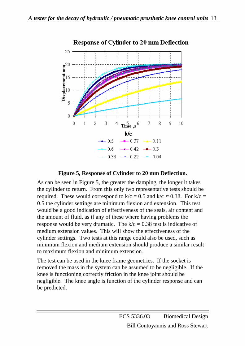
Figure 5, Response of Cylinder to 20 mm Deflection.
As can be seen in Figure 5, the greater the damping, the longer it takesthe cylinder to return. From this only two representative tests should berequired. These would correspond to k/c = 0.5 and k/c ≈ 0.38. For k/c =0.5 the cylinder settings are minimum flexion and extension. This testwould be a good indication of effectiveness of the seals, air content andthe amount of fluid, as if any of these where having problems theresponse would be very dramatic. The k/c ≈ 0.38 test is indicative ofmedium extension values. This will show the effectiveness of thecylinder settings. Two tests at this range could also be used, such asminimum flexion and medium extension should produce a similar resultto maximum flexion and minimum extension.
The test can be used in the knee frame geometries. If the socket isremoved the mass in the system can be assumed to be negligible. If theknee is functioning correctly friction in the knee joint should benegligible. The knee angle is function of the cylinder response and canbe predicted.

A tester for the decay of hydraulic / pneumatic prosthetic knee control units 14
ECS 5336.03 Biomedical Design
Bill Contoyannis and Ross Stewart
Figure 6, Response of Knee Unit, with different settings.
From the Figure 6 acceptable times for k/c = 0.5 would be 4 ± 1 secondand 5 to 6 seconds for k/c = 0.37 for all knee geometries. Response timesearlier than these indicate the fluid is not operating correctly. This givesa stopping knee angle of 5 degrees. Going to 0o is not recommended dueto the exponential nature of the response.
Failure criteria.
From plots of cylinder responses ( Figure 6) failure criteria can bedetermined.
Figure 7, Knee Units Response to different values of k/c.
Figure 7 plots the response of the knee to different cylinder conditions atthe knee. If the response is almost instantaneous (k/c >1 ), the resistancefrom the damper is negligible, indicating failure in this region. Similarly

A tester for the decay of hydraulic / pneumatic prosthetic knee control units 15
ECS 5336.03 Biomedical Design
Bill Contoyannis and Ross Stewart
if the time of the response over a long period, 30 seconds, the effect ofspring is minimal.
Test condition Possible cause offailure
Repair Option
Test time is shorterthan time specified.
Fluid leakage insystem.
Send unit into be serviced
Test time is longerthan specified time,cylinder does notreturn at all.
Spring failure. Send unit into be servicedor replaced.
Test time is longerthan time specified.
Excess friction inknee.
Clean and replace bearingsat knee joint
Squishing noise incylinder duringmotion
Air in cylinder Compress the unit, raisethe mode lever ( enteringflexion lock), extend unitand lower mode lever toallow flexion. May need tobe repeated until all air isout of unit.4 (suitable forCaTech and Mauch unitsonly).
Rough feel whenrotating piston rod.
Worn seals Send unit into be serviced.5
Table 5, Types of Failure and Possible Causes
Further testing is required to verify the test times. Test times for otherhydraulic and pneumatic controllers need to be established. If the timedisplacement plot is recorded further information regarding causes ofknee failure maybe obtained. Such as a response that had jumps couldindicate air in the unit.
Tests procedure.
The socket and cosmetic cover is removed from the prosthesis. Thetesting rig is attached to the knee frame and hydraulic unit. Thehydraulic controller settings are moved to minimum flexion andextension. The knee is then flexed 40o using the test frame. The frame isthen released allowing the knee to return to the original upright position.
A tester for the decay of hydraulic / pneumatic prosthetic knee control units 16
ECS 5336.03 Biomedical Design
Bill Contoyannis and Ross Stewart
The time the knee takes to return from the flexed position to the 5o markis recorded. The time of response should be 4 ± 1 second.
The test is then repeated with the controller settings on mediumextension and minimum flexion. The time of response should be 5 to 6seconds.
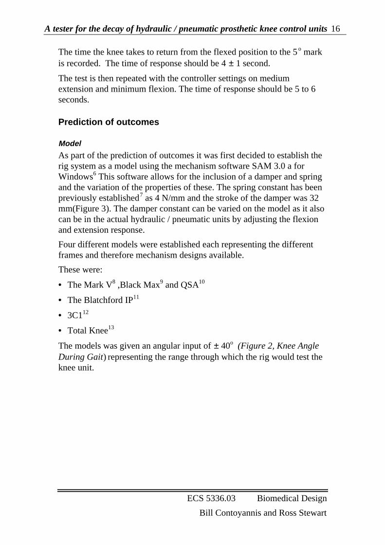
Prediction of outcomes
Model
As part of the prediction of outcomes it was first decided to establish therig system as a model using the mechanism software SAM 3.0 a forWindows6 This software allows for the inclusion of a damper and springand the variation of the properties of these. The spring constant has beenpreviously established7 as 4 N/mm and the stroke of the damper was 32mm(Figure 3). The damper constant can be varied on the model as it alsocan be in the actual hydraulic / pneumatic units by adjusting the flexionand extension response.
Four different models were established each representing the differentframes and therefore mechanism designs available.
These were:
• The Mark V8 ,Black Max9 and QSA10
• The Blatchford IP11
• 3C112
• Total Knee13
The models was given an angular input of ± 40o (Figure 2, Knee AngleDuring Gait) representing the range through which the rig would test theknee unit.
A tester for the decay of hydraulic / pneumatic prosthetic knee control units 17
ECS 5336.03 Biomedical Design
Bill Contoyannis and Ross Stewart
Figure 8 - Typical SAM6 window
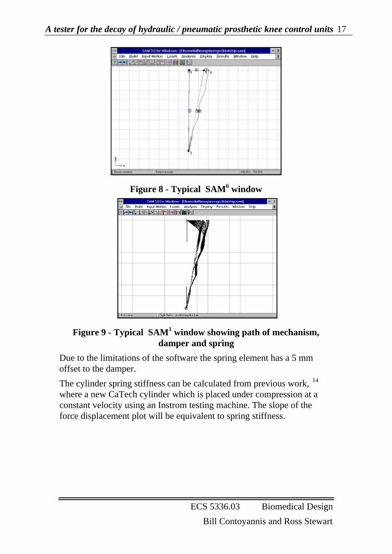
Figure 9 - Typical SAM1 window showing path of mechanism,damper and spring
Due to the limitations of the software the spring element has a 5 mmoffset to the damper.
The cylinder spring stiffness can be calculated from previous work, 14
where a new CaTech cylinder which is placed under compression at aconstant velocity using an Instrom testing machine. The slope of theforce displacement plot will be equivalent to spring stiffness.

A tester for the decay of hydraulic / pneumatic prosthetic knee control units 18
ECS 5336.03 Biomedical Design
Bill Contoyannis and Ross Stewart
Test Condition14 Test velocity, cm /min Slope, N/mm
Minimum Flexion 50 3.6
Medium Flexion 50 4
Maximum Flexion 50 4
Maximum Flexion 20 3.1
Medium Flexion 20 3.1
Minimum Flexion 20 3
Table 6, Spring Stiffness
Having established the model it can be used to correlate with theresponse in the actual system and then determine the damping responsefor a given setting. This can then be replicated in the model for eachframe. This iterative process should lead to an improved and accuratemodel for prediction of responses for a variety of frames.
Solution Specification - Tester
The test rig or tester can be separated into two components
• the structure or frame
• and the timer
Figure 10 - Proposed design of tester, with and without knee unit(note: timer not visible)

A tester for the decay of hydraulic / pneumatic prosthetic knee control units 19
ECS 5336.03 Biomedical Design
Bill Contoyannis and Ross Stewart
Structure
The structure of the test rig needs to ensure:
• each test starts and stops at the same position for each knee.
• Fit different knee frame types
The only common structure for all the knee frames is where they attachto the hydraulic cylinder and the knee axis. This is at the distal cylinderattachment point, knee axis and proximal cylinder attachment point.Even though the relative position of these varies with each knee it is theonly constant for the knees (Figure 11).
90.00°
AttachmentPoints
Figure 11, Test Rig Attachment Points
These points are used for both location, rotation and attachment of thetesting rig. This stops any 3 dimensional effects as all the knees will berotating in one plane, around the regular knee axis.
The 0 o knee angle or test starting point for all knee frames is aperpendicular line between the upper and lower axis (Figure 11).
As the knee frames vary greatly in size, distal and proximal attachmenttypes to the prothesis, it was decided to use the knee frame as part of thetest rig, stopping the need for a different test frame for each knee.
The test rig is shown in Figure 10. It consists of three sections. A lowerframe which attaches to the distal axis. This is in two independenthalves. Once the entire rig is attached to the prosthesis the lower frameis placed in a vice for convenience in conducting the tests.
The lower frame is attached to a fixed upper frame by two steel bars oneach side. The steel bars allow the upper frame to be raised or loweredfor each knee. The upper frame is attached to the knee axis and does notmove in the test. It consists of two "V" shaped bars on each side joinedat the top end of the V. The angle of the V is 50 o. This frame acts as thestarting and ending reference points (flexion and extension limits) for the
A tester for the decay of hydraulic / pneumatic prosthetic knee control units 20
ECS 5336.03 Biomedical Design
Bill Contoyannis and Ross Stewart
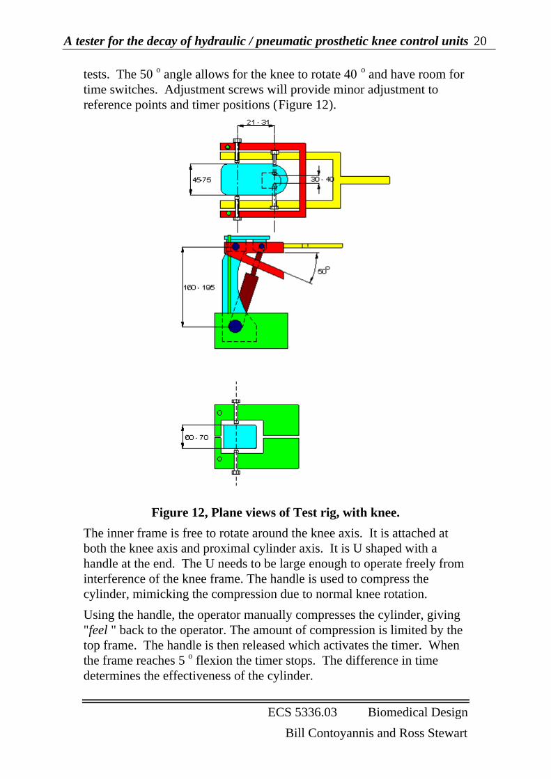
tests. The 50 o angle allows for the knee to rotate 40 o and have room fortime switches. Adjustment screws will provide minor adjustment toreference points and timer positions (Figure 12).
Figure 12, Plane views of Test rig, with knee.
The inner frame is free to rotate around the knee axis. It is attached atboth the knee axis and proximal cylinder axis. It is U shaped with ahandle at the end. The U needs to be large enough to operate freely frominterference of the knee frame. The handle is used to compress thecylinder, mimicking the compression due to normal knee rotation.
Using the handle, the operator manually compresses the cylinder, giving"feel " back to the operator. The amount of compression is limited by thetop frame. The handle is then released which activates the timer. Whenthe frame reaches 5 o flexion the timer stops. The difference in timedetermines the effectiveness of the cylinder.

A tester for the decay of hydraulic / pneumatic prosthetic knee control units 21
ECS 5336.03 Biomedical Design
Bill Contoyannis and Ross Stewart
Aluminium is used for construction. This will reduce the overall weightof the test rig. More importantly it will reduce the weight and inertia ofthe inner frame section.
The tests should be conducted with the knee in an upright position.Slight variations are acceptable. Excessive deviations will change theresponse of the cylinder as the force of the knee plate and the innersection of the test frame will vary depending on if gravity is workingwith or against the cylinder.
The test rig should give good repeatability of tests, as all axis of rotationremain constant regardless of orientation.
Obviously with different size knees there are minimum sizes that the testrig needs to be. These are set so the test rig will not interfere with theknee frame.
This leaves the critical construction being how the test rig actuallyattaches to the knee frame at the specified points. The attachmentmechanisms needs to accommodate all frames, and provide a secureattachment. This is complicated by the knees having different axisheads, from hex, screw and 2 point. The attachment points also need toallow the frame to rotate at these points.
Hex Socket
Frame
ThreadedBolt
Connection Bits
Figure 13, Schematic of attachment system
The end attachments will be commercially available tool bits. These areavailable in different shapes and sizes, with a common hex shaped base.The end bits will then attach to a hex head which is positioned inside alarge bolt. The bolt goes through the test rig and screws into position,locating and securing the test rig.

A tester for the decay of hydraulic / pneumatic prosthetic knee control units 22
ECS 5336.03 Biomedical Design
Bill Contoyannis and Ross Stewart
Timer
The specific monitoring function can be described as a simple timer withthe following general criteria:
• No permanent record is required of specific tests, therefore nohardcopy
• Time indication is only required for the return stoke of the unit
• Some type of indication of pass/ fail is required
• Some type of indication of scale or % performance is required
These criteria can be further analysed into specific functions which canbe defined as being required in two stages.
The first is those required to conduct the testing in order to establish thevalidity of this process and then the actual details of acceptable timeintervals for different systems, assuming the process is valid. These are:
• Timer start at bottom of range
• Timer stop when unit returns to top
• Output of time taken to return
This information would then be recorded manually and a series of testsconducted on hydraulic and pneumatic knee control units of variouscycle age to determine the characteristic response.
The second set of functions is used once the performance characteristicshave been established and are:
• The ability to store the desired response
• Timer start at bottom of range
• Timer stop when unit returns to top
• An alert as to pass or fail
• A monitor at fail to indicate the percentage (not accurately known atthis stage) of ideal performance.
An electronic timer 15 has been sourced which is commercially availableand can provide the required functions at both stages of the test rig use.The timer has a ‘count up’ and ‘timer’ function , both of which operatefrom a single contact which toggles on and off. The timer has a 10 mmLCD display and operates on a single LR44 1.5 volt battery. Thedimensions of the entire unit is H 65 mm x W 50 mm x D 10 mm. It is acommercially available for approximately $6 however a modification

A tester for the decay of hydraulic / pneumatic prosthetic knee control units 23
ECS 5336.03 Biomedical Design
Bill Contoyannis and Ross Stewart
would be required which involves the main operating contact switchbeing mounted onto the structure of the test rig.
The first stage of the testing would involve the ‘count up’ setting whichwould simply time the return in seconds. This time is repeated andmonitored for the same and other units.
The second stage, or general clinical use stage, involves the timer beingset to the ‘timer’ option and the required performance characteristic isstored in memory (available in the basic unit). If the unit passes the test,that is reaches the top of the rig within the appropriate time, an alarm willsound and reset the unit for a further test. If the unit reaches the top priorto the appropriate time (which is the mode of failure of the damper asonly the spring is now operating), a different alarm sounds and the stopwatch function holds the time remaining for the optimal response. It ishypothesised that this time compared to the ideal time will give anindication of the percentage decay of the unit.
Feasibility /Evaluation
re evaluate criteria/compromises to objectives
• Inexpensive-At this stage it is difficult to define an accurate cost, particularly whilethe prototype has not been completed. The estimate of cost is asfollows:
Table 7 - Costs for prototype
Material Cost $
Aluminium 50
Bolts 20
hexagonal adaptors 24
Timer 10
Labour 0
Structure/ frame 600
Timer modification 200
Total 904
A tester for the decay of hydraulic / pneumatic prosthetic knee control units 24
ECS 5336.03 Biomedical Design
Bill Contoyannis and Ross Stewart
This figure is between the cost of a new unit and servicing, however itshould be within the acceptable range of the cost of assessmentequipment ($600 - $3000)
• Small and minimally intrusive -The tester is small enough to be portable and should weigh less than akilogram. This means that it would not be obtrusive in the clinicalenvironment. A compromise of the structure is that it ideally needs tobe fixed in a vice. This improves the structural integrity of the unit andis ideal for the repeatability of the tests. The unit will howeverfunction outside of a vice but this may effect the results and is yet tobe investigated as the prototype is required for this.
• An adequate indication of time response as per study1 will beachieved. Further verification as to the validity will have to bedetermined.
• The current tester design can cope with the variety of prosthetic kneesframes. Table 1.
• The current tester design allows for the investigation of knees as perthe protocol.
• Feeling -The current design allows the clinician to manually deflect the unitwhile in the prosthesis.
• Range-.The units can be adjusted across a range of responses and this does notalter the checking or testing process which will be performed. Thetester also does not need to be removed or re- adjusted to alter therange.
• Permanent attachment .It is impractical to permanently attach this design. This criterion wascompromised for the performance of the tester and the ability toprovide feeling.
• Indication of percentage of decay-. An indication of percentage decay/performance is available due to thetimer mechanism providing a value at which a certain test parameterwas reached (ie too soon by x seconds, or too late by y seconds.) Thetesting will establish if these are valid values or indicators.
• Repeatability- The test rig should give a repeatable response particularly when

A tester for the decay of hydraulic / pneumatic prosthetic knee control units 25
ECS 5336.03 Biomedical Design
Bill Contoyannis and Ross Stewart
mounted on a vice. The prototype will need to be tested to establishthe error margin for that repeatability.
The criteria and objectives have generally been met with a compromiseaffecting the size and portability of the tester. This should mean that thetester can be used to establish the test validity of the performanceresponse of hydraulic and pneumatic knee control units in the clinicalsituation.
Implementation/development
A prototype is currently (11/96) being constructed and is expected to becompleted by the end of this year.The Amputee unit of Caulfield General Medical Centre has agreed to beinvolved in the initial trialling of the tester as they see a need for such aunit. This is expected to commence in early 1997 with an aim ofconducting 50 tests by mid 1997. The validity of the tests and tester willthen be reassessed.

A tester for the decay of hydraulic / pneumatic prosthetic knee control units 26
ECS 5336.03 Biomedical Design
Bill Contoyannis and Ross Stewart
Appendix
Response of Hydraulic unit to Test
x
c k
x’
( )
cx kx Fi t Fik
xx
c sx s x kx sFi
sc k
x sFi
s cs kt
x t x e
ex t
x
k
ct
k
ct
& ( ), ’
( ) ( ) ( )
( )( )
( )
( ) ( )
( )
+ = =′
− + = = =
=+
=
= ′ −
= −′
−
−
−
µ
µ
= preloading force, = displacement due to applied force
, damping coefficent, spring stiffness
Unit step function
0
1
1
Geometry of Knee Frames.
y
ly
l
x
0h
z
h y
l h z z l h
x z
y
x l h
y
y x l y
y x l
xy
l y x xy
=
= + ⇒ = −
= + = + −
⇒ − = −
∴ = + −
= + −
sin
cos
( cos ) sin
cos
cos
θ
θ
θ θ
θ
θ
2 2 2 2 2
2 2
2 2 2 2
2 2 2
2 2
2
2
Figure 14,Geometry of cylinder at θ = 90 o and random.
α = knee angle, θ = 90o - α

A tester for the decay of hydraulic / pneumatic prosthetic knee control units 27
ECS 5336.03 Biomedical Design
Bill Contoyannis and Ross Stewart
Knee frame variations
Figure 15, Blatchford Total Knee, left, Otto Bock 3C1, right.
Figure 16, USMC Mark V, USMC Blackmax, Hosmer QSA

A tester for the decay of hydraulic / pneumatic prosthetic knee control units 28
ECS 5336.03 Biomedical Design
Bill Contoyannis and Ross Stewart
Figure 17, Mark V knee in Prosthesis, Different Knee HydraulicUnits
References1 Experimental Investigation of the decaying Performance of hydraulic knee controllers, Devenport. J.,Mechefske. C.. 1995. Final Year Project, VUT.2 Price of CaTech unit from TechGUIDE, 1996.3 Price of service from G.W. Masson & Sons.4 From Manual for the Henschke - Mauch "Hydraulik", Mauch Laboratories, 1976.5 From discussions with Martin Masson, G.W. Masson & Sons.6 SAM 3.0 a for Windows, ARTAS -Engineering Software, Het Puyven 162, NL - 5672 RJ Nuenen,The Netherlands.7 Spring Constant trial with John Miller, Mechanical Engineering Laboratory, January 1995.8 Mark V knee frame from - USMC - 180 N.San Gabriel Blvd, Pasadena, CA, USA9 Black Max knee frame from - USMC - 180 N.San Gabriel Blvd, Pasadena, CA, USA10 QSA Knee frame from - Hosmer - 561 Division St Cambell, CA, USA11 Blatchford IP from Endolite system- Blatchford Unit 6 Sherrington Way, Basingstoke, HampshireRG22 4LU, England.12 3C1 - Otto Bock Orthopadishe Industrie GmbH & Co, Postfach 12 60 D-37105 Duderstadt,Germany.13 Total Knee from Endolite system- Blatchford Unit 6 Sherrington Way, Basingstoke, HampshireRG22 4LU, England.14 From tests conducted at the Mechanical Engineering Laboratory15 ‘Electronic TIMER CLOCK - Registered design no. 1 049 496, available in Australia through RS