regulated high voltage dc power supplies 124 west main street, po box 317, high bridge, nj...
TRANSCRIPT

ENGINEERINGEXCELLENCE
UNMATCHEDREPUTATIONFOR QUALITY
CUSTOMIZEDSOLUTIONS
HIGH VOLTAGELEADERSHIP
GUARANTEEDPERFORMANCE
INNOVATIVETECHNOLOGY
124 West Main Street, PO Box 317, High Bridge, NJ 08829-0317(908) 638-3800 • Fax (908) 638-3700 • www.glassmanhv.com
Regulated High Voltage DC Power SuppliesGLASSMAN HIGH VOLTAGE INC.Designing Solutions for High Voltage Power Supply Applications
www.glassmanhv.com
1
Please visit our newly expandedwebsite at www.glassmanhv.com tolearn more about our product offeringsand technology. We are constantlyupdating the site with new products,product updates, company news andtechnical information that will be ofinterest for high voltage users. We alsoprovide contact information in order toreach our application design team forspecial requirements.
The site is simple to navigate with aproduct locator on the homepage thatqueries by desired voltage or powerlevel in order to choose the “rightsolution” for your high voltage needs.
The Company
Since 1977, Glassman High Voltagehas been committed to producing thefinest High Voltage DC power suppliesat affordable prices. More than astandard design facility, Glassman hasestablished an enviable reputation fordeveloping High Voltage Solutions tomeet specific customer needs, byemploying a combination of innovativedesign technology and manufacturingflexibility. For example, Glassmanpioneered the use of air as the primarydielectric for power supply high voltageassemblies, eliminating the weight andserviceability problems of otherdielectric medium as well as reliabilityconstraints of solid dielectrics. Todaythe Glassman name is synonymous forhigh quality and technical innovation inthe High Voltage Industry. Glassman’sservice and support of it’s domesticand International customers’ is secondto none in their industry, and no oneoffers a more thorough or extensivewarranty on their products.
The industry’s primary resource forhigh voltage power supplies, Glassmanprovides a full-range of high voltageregulated DC switching power suppliesfor medical, industrial, and scientificapplication. Models range from 0 to500 kV DC, 15W to 40 kW. and areutilized in a broad range of commercialand research settings with leadingOEM’s, National laboratories and MajorUniversities.
www.glassmanhv.com

6
5
4
3
2
1
2
Basic CircuitDesign-High FrequencySwitchmode
• Glassman’s power supply designtopologies are based uponswitchmode power conversiontechnology, while operating atfrequencies approaching 60kHz. The“switcher” is the design of choicefor many industrial and medicalapplications because of a desirablecombination of high efficiency, smallsize, low weight and in the case ofhigh voltages, increased safety.
Power Factor• Power factor (PF) is the ratio of real
power to a load, as measured inwatts, to the apparent powermeasured in volt-amperes. Forsinusoidal voltages and currents, PFequals the cosine of the phase anglebetween the voltage applied to aload and the current passing throughthe load. In an ideal case, when thevoltage and current are exactly inphase, the power factor is unity.
ArcQuench/Arc SensingCircuitry
• Included as a standard feature onmany Glassman power supplies,proprietary arc sensing and quenchcircuitry will suppress arcingconditions that can occur regularly inhigh voltage applications and providemaximum safety and protection forboth the power supply and customerload during processing relatedapplications, including Magnetronsputtering, Electron-beamevaporation, and Ion-beamdeposition to name a few. Theseproducts are also highly utilized inthe research market, as a generalpurpose laboratory power source.
Air Insulation• Glassman supplies are unique in that
they use air as the primary dielectricmedium. Many competitive suppliesuse oil or solid encapsulation. Theuse of air insulation has considerableadvantages. Reduced weight is one.More importantly, air insulation leadsto improved serviceability. Individualcomponents can be replaced, ifnecessary, without the need to scrapan entire assembly.
Manufacturing• We manufacture many different
series of regulated high voltagepower supplies and within eachseries there are many standardmodels. Such a large array ofmodels would be a manufacturingnightmare without the use ofmodular construction. Manystandard or modified modules arecommon to different models andseries. This commonality providesthe cost and time savingsassociated with volume productionwhile still allowing the schedulingflexibility of custom assembly.
Warranty• Glassman High Voltage, Inc. warrants
standard power supplies to be freefrom defects in materials andworkmanship for three years fromdate of shipment. OEM and modifiedstandard power supplies arewarranted for one year from date ofshipment. A formal warranty isavailable.
Glassman High Voltage DC Power Supplies…better by design!
The proper selection of a high voltage power supply for a particular application is amore difficult task than the selection of a low voltage supply. For one thing, today’shigh voltage regulated power supplies are often more complex than their low voltagecounterparts. The selection of high voltage supplies also requires extra attention to thedesign features and construction techniques that contribute to safety and protectionagainst failures.
Any high voltage DC power supply must fulfill certain basic requirements. It mustmeet maximum output voltage and current needs, provide ripple suppression, staticline regulation, and static load regulation that is adequate for the application, and itmust operate with the available AC input line voltage and frequency. Otherconsiderations, however, may be even more important in certain applications.

3
Welcome to Glassman High Voltage
GLASSMAN EUROPE Limited (UK) GLASSMAN JAPAN High Voltage Limited+44 1256 883007 FAX +44 1256 883017 +81 45 902 9988 FAX +81 45 902 2268E-mail: [email protected] E-mail: [email protected]
©Glassman High Voltage, Inc. Printed in the U.S.A. 4/10/02
Hello, I'm Sandy Glassman.
Allow me to introduce you to our company, our products, and mostimportantly, our people.
Beginning with it's inception in 1977, Glassman High Voltage has become thepremier worldwide supplier of high voltage power supply technology tooriginal equipment manufacturers and a very diverse group of researchfacilities. Glassman products feature our proprietary, air-insulation technologyand inverter circuit designs that ensure long-term stability and reliability.
Our people have the talent, ingenuity, and dedication to meet, and exceed,your most demanding requirements. Because of our experience and creativitywith high voltage technology, we are uniquely qualified to lead design anddevelopment projects for specialized equipment. You will discover thatworking with our sales and engineering staffs, is more like a true partnershipthan a vendor/customer relationship.
If the models on the following pages do not meet your requirements, pleasedon't hesitate to contact us so that we may offer modifications or newdesigns. It is our commitment to excellence and innovation that has fueled ourgrowth and customer loyalty.
If there is anything I can personally do to enhance your experience with ourcompany, call me directly at 908-638-3800, or Email [email protected].
Yours truly,
Sandy GlassmanPresident
Designing Solutions for High Voltage Power Supply Applications
GLASSMAN HIGH VOLTAGE INC.124 West Main Street, PO Box 317, High Bridge, NJ 08829-0317(908) 638-3800 • Fax (908) 638-3700 • www.glassmanhv.com • [email protected]

4
GLASSMAN HIGH VOLTAGE INC. www.glassmanhv.com USA (908) 638-3800 • FAX (908) [email protected]
Power Supply Selection ChartSERIES STYLE VOLTAGES POWER
RS-232 Digital Interface Option
MJ Module 3 kV to 30 kV Models 15 W
MK Module 1 kV to 60 kV Models 75 W
MR Module 1 kV to 5 kV Models 300 W
ML Module 8 kV to 60 kV Models 300 W
EL 2U Rack 1 kV to 60 kV Models 45 W
EH 2U Rack 1 kV to 60 kV Models 100 W
FC 1U Rack 1 kV to 60 kV Models 120 W
WR 3U Rack 85 kV to 125 kV Models 250 W
ER 2U Rack 1 kV to 75 kV Models 300 W
FX 1U Rack 1 kV to 60 kV Models 300 W
EW 2U Rack 1 kV to 60 kV Models 500 W
WK 3U Rack 80 kV to125 kV Models 500 W
EK 2U Rack 1 kV to 60 kV Models 600 W
PG-LR 3U Rack + Open Stacks 100 kV to 400 kV Models 250 W/500 W

5
EUROPE (UK) (1256) 883007 • FAX (1256) 883017 JAPAN (045) 902-9988 • FAX (045) [email protected] [email protected]
SERIES STYLE VOLTAGES POWER
PG 3U Rack + Open Stacks(s) 100 kV to 400 kV Models 500 W/1000 W
WX 3U Rack 1 kV to 75 kV Models 1 kW
LX 5U Rack 1 kV to 150 kV Models 1 kW
EQ 2U Rack 1 kV to 60 kV Models 1.2 kW
LT 5U Rack 1 kV to 150 kV Models 2 kW
OS 3U Rack + Open Stack 200 kV to 450 kV Models 2 kW
KL 4U Rack 1 kV to 30 kV Models 3 kW
LK 5U Rack 40 kV to 100 kV Models 3 kW
LH 6U Rack 1 kV to 100 kV Models 5 kW
PK 6/12U Rack 3 kV to 75 kV Models 4/8 kW
PK 9/18U Rack 80 kV to 125 kV Models 4/8 kW
PK 3U Rack + Open Stack(s) 150 kV to 400 kV Models 4/8 kW
SH 10/20U Rack 1 kV to 100 kV Models 8/16 kW
Note: Panel Height U = 1-3/4"

7
EUROPE (UK) (1256) 883007 • FAX (1256) 883017 JAPAN (045) 902-9988 • FAX (045) [email protected] [email protected]
RS-232 IntelligentPower Supply SerialInterface Option
This microcontroller interface is offeredas an option for Glassman High Voltagepower supplies.
Its purpose is to provide remote controlcapability of analog program signals,analog monitor signals, and HV enableusing standard RS-232 interfacecomputer control. (Additional statusindicators are provided on supplies whichnormally have these signals availableexternally.)
SpecificationsINPUT: Power is provided by the HVPS through the“D” connector interconnection between thecontroller and the HVPS for all modelapplications except for the MJ, MK, and FCseries. These models require an externalpower source of +20 to 30 VDC at 200 mAminimum.
RESOLUTION: 0.1%, 10 bit A/D and 12 bit D/A. Theaccuracy of the HV output and monitors aredetermined by the HVPS specifications.
PROTOCOL: RS-232C is used with single-endedtransmission over relatively short lines. Thisstandard defines the electrical characteristicsfor the interfacing of Data TerminalEquipment (DTE) and Data CommunicationsEquipment (DCE). For our case the hostcomputer is the DTE and the Glassman HVPower Supply equipment is the DCE.
The power supply Interface acts strictly as aslave device. It will not transmit anymessages over the data link unless it is firstqueried by the host computer.
The data are conveyed using ASCII encodedcharacter strings. Scale factors are applied tothe analog data by the host computer. Theinstruction manual provides signalinformation and configuration details.
The functions that can be controlled andmonitored are dependent upon the functionsprovided for each HVPS series.
COMPUTER INTERFACE CONNECTORFemale 9 Pin “D” connector (RS-232 port).Instructions for wiring the mating connectorfor “null modem” operation are detailed inthe instruction manual provided.
POWER SUPPLY INTERFACE CONNECTOR: Female 25 Pin “D” connector. The signalconnections vary as a function of the HVPSmodel.
ACCESSORIES: 3 foot shielded HVPS to controller interfacecable including chassis return ground wire,10 foot RS-232 “null modem” controller tohost computer cable, Windows PC controlsoftware.
CONTROL SOFTWARE: Software is provided on a 31/2" floppydiskette which allows the user to remotelyoperate the HVPS from a PC with MSWindows 98 or 2000 operating systems.The program consists of a main window anda pull down configuration menu. The mainwindow allows programming and readbackof the control signals, operation of the digitalinterface functions and reporting, anddisplays messages indicating the status ofthe HVPS and to report any errors.
Note: This option must be ordered with thepower supply. It cannot be added toan existing supply by the user.Contact your Glassman representativefor factory upgrade availability.
Program Screen Outline
Modules are 5"L x 3" W x 5" H
8
GLASSMAN HIGH VOLTAGE INC. www.glassmanhv.com USA (908) 638-3800 • FAX (908) [email protected]
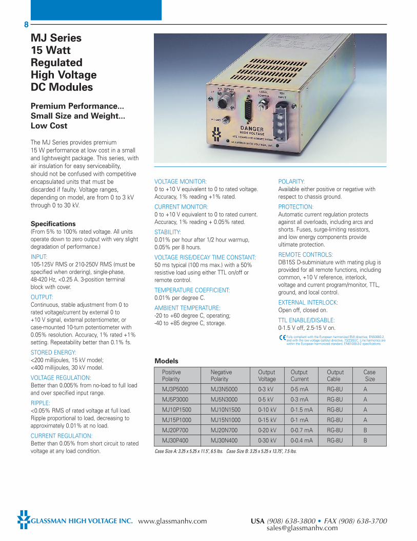
MJ Series15 WattRegulated High VoltageDC Modules
Premium Performance...
Small Size and Weight...
Low Cost
The MJ Series provides premium15 W performance at low cost in a smalland lightweight package. This series, withair insulation for easy serviceability,should not be confused with competitiveencapsulated units that must bediscarded if faulty. Voltage ranges,depending on model, are from 0 to 3 kVthrough 0 to 30 kV.
Specifications(From 5% to 100% rated voltage. All unitsoperate down to zero output with very slightdegradation of performance.)
INPUT: 105-125V RMS or 210-250V RMS (must bespecified when ordering), single-phase,48-420 Hz, <0.25 A. 3-position terminalblock with cover.
OUTPUT: Continuous, stable adjustment from 0 torated voltage/current by external 0 to +10 V signal, external potentiometer, orcase-mounted 10-turn potentiometer with0.05% resolution. Accuracy, 1% rated +1%setting. Repeatability better than 0.1% fs.
STORED ENERGY:<200 millijoules, 15 kV model;<400 millijoules, 30 kV model.
VOLTAGE REGULATION: Better than 0.005% from no-load to full loadand over specified input range.
RIPPLE: <0.05% RMS of rated voltage at full load.Ripple proportional to load, decreasing toapproximately 0.01% at no load.
CURRENT REGULATION: Better than 0.05% from short circuit to ratedvoltage at any load condition.
VOLTAGE MONITOR: 0 to +10 V equivalent to 0 to rated voltage.Accuracy, 1% reading +1% rated.
CURRENT MONITOR: 0 to +10 V equivalent to 0 to rated current.Accuracy, 1% reading + 0.05% rated.
STABILITY: 0.01% per hour after 1/2 hour warmup,0.05% per 8 hours.
VOLTAGE RISE/DECAY TIME CONSTANT: 50 ms typical (100 ms max.) with a 50%resistive load using either TTL on/off orremote control.
TEMPERATURE COEFFICIENT: 0.01% per degree C.
AMBIENT TEMPERATURE:-20 to +60 degree C, operating;-40 to +85 degree C, storage.
POLARITY: Available either positive or negative withrespect to chassis ground.
PROTECTION: Automatic current regulation protects against all overloads, including arcs andshorts. Fuses, surge-limiting resistors, and low energy components provideultimate protection.
REMOTE CONTROLS:DB15S D-subminiature with mating plug isprovided for all remote functions, includingcommon, +10 V reference, interlock,voltage and current program/monitor, TTL,ground, and local control.
EXTERNAL INTERLOCK: Open off, closed on.
TTL ENABLE/DISABLE:0-1.5 V off, 2.5-15 V on.
Fully compliant with the European harmonized EMI directive, EN50082-2,and with the low voltage (safety) directive, 73/23/EEC. Line harmonics arewithin the European harmonized standard, EN61000-3-2 specifications.
Models
Case Size A: 3.25 x 5.25 x 11.5", 6.5 lbs. Case Size B: 3.25 x 5.25 x 13.75", 7.5 lbs.
Positive Negative Output Output Output CasePolarity Polarity Voltage Current Cable Size
MJ3P5000 MJ3N5000 0-3 kV 0-5 mA RG-8U A
MJ5P3000 MJ5N3000 0-5 kV 0-3 mA RG-8U A
MJ10P1500 MJ10N1500 0-10 kV 0-1.5 mA RG-8U A
MJ15P1000 MJ15N1000 0-15 kV 0-1 mA RG-8U A
MJ20P700 MJ20N700 0-20 kV 0-0.7 mA RG-8U B
MJ30P400 MJ30N400 0-30 kV 0-0.4 mA RG-8U B
9
EUROPE (UK) (1256) 883007 • FAX (1256) 883017 JAPAN (045) 902-9988 • FAX (045) [email protected] [email protected]
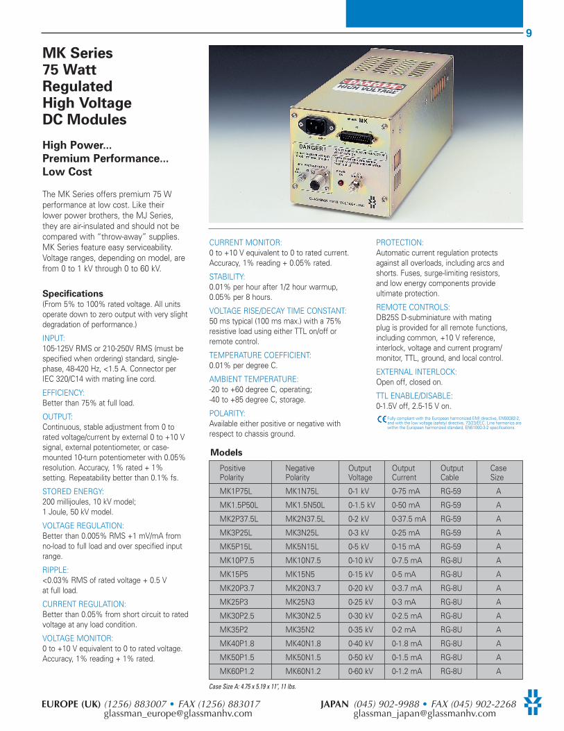
MK Series 75 WattRegulated High VoltageDC Modules
High Power...
Premium Performance...
Low Cost
The MK Series offers premium 75 Wperformance at low cost. Like their lower power brothers, the MJ Series, they are air-insulated and should not becompared with “throw-away” supplies.MK Series feature easy serviceability.Voltage ranges, depending on model, arefrom 0 to 1 kV through 0 to 60 kV.
Specifications(From 5% to 100% rated voltage. All unitsoperate down to zero output with very slightdegradation of performance.)
INPUT: 105-125V RMS or 210-250V RMS (must bespecified when ordering) standard, single-phase, 48-420 Hz, <1.5 A. Connector perIEC 320/C14 with mating line cord.
EFFICIENCY:Better than 75% at full load.
OUTPUT: Continuous, stable adjustment from 0 torated voltage/current by external 0 to +10 Vsignal, external potentiometer, or case-mounted 10-turn potentiometer with 0.05%resolution. Accuracy, 1% rated + 1%setting. Repeatability better than 0.1% fs.
STORED ENERGY: 200 millijoules, 10 kV model;1 Joule, 50 kV model.
VOLTAGE REGULATION:Better than 0.005% RMS +1 mV/mA fromno-load to full load and over specified inputrange.
RIPPLE: <0.03% RMS of rated voltage + 0.5 V at full load.
CURRENT REGULATION: Better than 0.05% from short circuit to ratedvoltage at any load condition.
VOLTAGE MONITOR: 0 to +10 V equivalent to 0 to rated voltage.Accuracy, 1% reading + 1% rated.
CURRENT MONITOR:0 to +10 V equivalent to 0 to rated current.Accuracy, 1% reading + 0.05% rated.
STABILITY: 0.01% per hour after 1/2 hour warmup,0.05% per 8 hours.
VOLTAGE RISE/DECAY TIME CONSTANT: 50 ms typical (100 ms max.) with a 75%resistive load using either TTL on/off orremote control.
TEMPERATURE COEFFICIENT:0.01% per degree C.
AMBIENT TEMPERATURE: -20 to +60 degree C, operating;-40 to +85 degree C, storage.
POLARITY:Available either positive or negative withrespect to chassis ground.
PROTECTION: Automatic current regulation protects against all overloads, including arcs andshorts. Fuses, surge-limiting resistors, and low energy components provideultimate protection.
REMOTE CONTROLS: DB25S D-subminiature with matingplug is provided for all remote functions,including common, +10 V reference,interlock, voltage and current program/monitor, TTL, ground, and local control.
EXTERNAL INTERLOCK: Open off, closed on.
TTL ENABLE/DISABLE: 0-1.5V off, 2.5-15 V on.
Fully compliant with the European harmonized EMI directive, EN50082-2,and with the low voltage (safety) directive, 73/23/EEC. Line harmonics arewithin the European harmonized standard, EN61000-3-2 specifications.
Case Size A: 4.75 x 5.19 x 11", 11 lbs.
Models
Positive Negative Output Output Output CasePolarity Polarity Voltage Current Cable Size
MK1P75L MK1N75L 0-1 kV 0-75 mA RG-59 A
MK1.5P50L MK1.5N50L 0-1.5 kV 0-50 mA RG-59 A
MK2P37.5L MK2N37.5L 0-2 kV 0-37.5 mA RG-59 A
MK3P25L MK3N25L 0-3 kV 0-25 mA RG-59 A
MK5P15L MK5N15L 0-5 kV 0-15 mA RG-59 A
MK10P7.5 MK10N7.5 0-10 kV 0-7.5 mA RG-8U A
MK15P5 MK15N5 0-15 kV 0-5 mA RG-8U A
MK20P3.7 MK20N3.7 0-20 kV 0-3.7 mA RG-8U A
MK25P3 MK25N3 0-25 kV 0-3 mA RG-8U A
MK30P2.5 MK30N2.5 0-30 kV 0-2.5 mA RG-8U A
MK35P2 MK35N2 0-35 kV 0-2 mA RG-8U A
MK40P1.8 MK40N1.8 0-40 kV 0-1.8 mA RG-8U A
MK50P1.5 MK50N1.5 0-50 kV 0-1.5 mA RG-8U A
MK60P1.2 MK60N1.2 0-60 kV 0-1.2 mA RG-8U A

10
GLASSMAN HIGH VOLTAGE INC. www.glassmanhv.com USA (908) 638-3800 • FAX (908) [email protected]
MR Series 300 WattRegulated High VoltageDC Modules
Complies With
IEC & CSA 950 And
UL 1950 Standards As
A Power Supply
Component
The MR Series, with outputs from 0 to1 kV through 0 to 5 kV, is designed tomeet international safety approvals. It ispackaged as a space-saving module thatavoids the cost of expensive panels anddisplays. However, no compromises inperformance and operating features havebeen made. The result is a power supplythat offers outstanding value for a widerange of demanding applications.
Specifications(From 5% to 100% rated voltage. All unitsoperate down to zero output with very slightdegradation of performance.)
INPUT: 103-132V RMS or 198-264V RMS (must bespecified when ordering), single-phase,48-63 Hz, <6 A. Connector per IEC 320/V1with mating line cord.
EFFICIENCY:Typically 85% at full load.
OUTPUT: Continuous, stable adjustment from 0 torated voltage and current through acombination of mounted 10-turnpotentiometer, with 0.05% resolutionexternal 0 to 10 V, or externalpotentiometers. Repeatability, <0.1% fs.Accuracy, 0.25% of rated + 1% of setting.
STORED ENERGY: <0.5 joules.
VOLTAGE REGULATION:<0.005% for line variations. For loadvariations, add 1 mV/mA.
RIPPLE: <0.02% RMS of rated voltage+ 300 mV RMS
CURRENT REGULATION: <0.1% of rated current from short circuit torated voltage at any set current.
VOLTAGE MONITOR: 0 to 10 V for zero rated voltage. Accuracy,1% reading + 0.25% of rated voltage.
CURRENT MONITOR:0 to 10 V for zero to rated current. Accuracy,1% reading + 0.05% of rated current.
STABILITY: 0.01% per hour after 1/2 hour warmup,0.05% per 8 hours.
OUTPUT VOLTAGE TIME CONSTANT: Typically 50 ms rise or decay timeconstant using TTL on/off or remotevoltage control with a minimum of 15%resistive load.
TEMPERATURE COEFFICIENT:0.01% per degree C.
AMBIENT TEMPERATURE: -20 to +40 degree C, operating;-40 to +85 degree C, storage.
POLARITY:Available either positive or negative withrespect to chassis ground.
PROTECTION: User-selected automatic current regulationor current trip protects against all overloads,including arcs and short circuits. Fuses,surge-limiting resistors, and low-energycomponents provide ultimate protection.
ACCESSORIES: Detachable 8-foot HV cable (see Modelschart for choice of output connector andwire type) and 6-foot detachable linecord provided.
REMOTE CONNECTIONS:Common, +10 V reference, interlock, current program, current monitor, voltageprogram, voltage monitor, TTL HV enable,current regulation/trip, and chassis ground.
EXTERNAL INTERLOCK: Open off, closed on.
TTL ENABLE/DISABLE: 0-1.5 V off, 2.5-15 V on.
Fully compliant with the European harmonized EMI directive, EN50082-2,and with the low voltage (safety) directive, 73/23/EEC. Line harmonics arewithin the European harmonized standard, EN61000-3-2 specifications.
Models (SHV connector)Positive Negative Output Output Output Polarity Polarity Voltage Current Cable
MR1P300L MR1N300L 0-1 kV 0-300 mA
MR1.5P200L MR1.5N200L 0-1.5 kV 0-200 mA
MR2P150L MR2N150L 0-2 kV 0-150 mA RG - 59
MR3P100L MR3N100L 0-3 kV 0-100 mA
MR5P60L MR5N60L 0-5 kV 0-60 mA
Modules are 3.38" H x 7.25" W x 16" D, weight less than 11 lbs. SHV version shown on left, Alden connector on right
Models (Alden connector)
Positive Negative Output Output Output Polarity Polarity Voltage Current Cable
MR1P300 MR1N300 0-1 kV 0-300 mA
MR1.5P200 MR1.5N200 0-1.5 kV 0-200 mA
MR2P150 MR2N150 0-2 kV 0-150 mA Silicone wire
MR3P100 MR3N100 0-3 kV 0-100 mA
MR5P60 MR5N60 0-5 kV 0-60 mA
11
EUROPE (UK) (1256) 883007 • FAX (1256) 883017 JAPAN (045) 902-9988 • FAX (045) [email protected] [email protected]
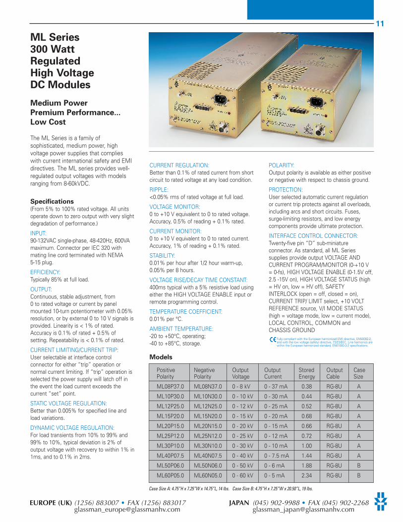
ML Series300 WattRegulated High VoltageDC Modules
Medium Power
Premium Performance...
Low Cost
The ML Series is a family ofsophisticated, medium power, highvoltage power supplies that complieswith current international safety and EMIdirectives. The ML series provides well-regulated output voltages with modelsranging from 8-60kVDC.
Specifications(From 5% to 100% rated voltage. All unitsoperate down to zero output with very slightdegradation of performance.)
INPUT: 90-132VAC single-phase, 48-420Hz, 600VAmaximum. Connector per IEC 320 withmating line cord terminated with NEMA5-15 plug.
EFFICIENCY: Typically 85% at full load.
OUTPUT: Continuous, stable adjustment, from0 to rated voltage or current by panelmounted 10-turn potentiometer with 0.05%resolution, or by external 0 to 10 V signals isprovided. Linearity is < 1% of rated.Accuracy is 0.1% of rated + 0.5% ofsetting. Repeatability is < 0.1% of rated.
CURRENT LIMITING/CURRENT TRIP: User selectable at interface controlconnector for either “trip” operation ornormal current limiting. If “trip” operation isselected the power supply will latch off inthe event the load current exceeds thecurrent “set” point.
STATIC VOLTAGE REGULATION: Better than 0.005% for specified line andload variations.
DYNAMIC VOLTAGE REGULATION: For load transients from 10% to 99% and99% to 10%, typical deviation is 2% ofoutput voltage with recovery to within 1% in1ms, and to 0.1% in 2ms.
CURRENT REGULATION: Better than 0.1% of rated current from shortcircuit to rated voltage at any load condition.
RIPPLE: <0.05% rms of rated voltage at full load.
VOLTAGE MONITOR: 0 to +10 V equivalent to 0 to rated voltage.Accuracy, 0.5% of reading + 0.1% rated.
CURRENT MONITOR: 0 to +10 V equivalent to 0 to rated current.Accuracy, 1% of reading + 0.1% rated.
STABILITY: 0.01% per hour after 1/2 hour warm-up,0.05% per 8 hours.
VOLTAGE RISE/DECAY TIME CONSTANT: 400ms typical with a 5% resistive load usingeither the HIGH VOLTAGE ENABLE input orremote programming control.
TEMPERATURE COEFFICIENT: 0.01% per °C.
AMBIENT TEMPERATURE: -20 to +50°C, operating; -40 to +85°C, storage.
POLARITY:Output polarity is available as either positiveor negative with respect to chassis ground.
PROTECTION: User selected automatic current regulationor current trip protects against all overloads,including arcs and short circuits. Fuses,surge-limiting resistors, and low energycomponents provide ultimate protection.
INTERFACE CONTROL CONNECTOR: Twenty-five pin “D” sub-miniatureconnector. As standard, all ML Seriessupplies provide output VOLTAGE ANDCURRENT PROGRAM/MONITOR (0-+10 V= 0-fs), HIGH VOLTAGE ENABLE (0-1.5V off,2.5 -15V on), HIGH VOLTAGE STATUS (high= HV on, low = HV off), SAFETYINTERLOCK (open = off, closed = on),CURRENT TRIP/ LIMIT select, +10 VOLTREFERENCE source, V/I MODE STATUS(high = voltage mode, low = current mode),LOCAL CONTROL, COMMON andCHASSIS GROUND
Fully compliant with the European harmonized EMI directive, EN50082-2,and with the low voltage (safety) directive, 73/23/EEC. Line harmonics arewithin the European harmonized standard, EN61000-3-2 specifications.
Models
Positive Negative Output Output Stored Output CasePolarity Polarity Voltage Current Energy Cable Size
ML08P37.0 ML08N37.0 0 - 8 kV 0 - 37 mA 0.38 RG-8U A
ML10P30.0 ML10N30.0 0 - 10 kV 0 - 30 mA 0.44 RG-8U A
ML12P25.0 ML12N25.0 0 - 12 kV 0 - 25 mA 0.52 RG-8U A
ML15P20.0 ML15N20.0 0 - 15 kV 0 - 20 mA 0.68 RG-8U A
ML20P15.0 ML20N15.0 0 - 20 kV 0 - 15 mA 0.66 RG-8U A
ML25P12.0 ML25N12.0 0 - 25 kV 0 - 12 mA 0.72 RG-8U A
ML30P10.0 ML30N10.0 0 - 30 kV 0 - 10 mA 1.00 RG-8U A
ML40P07.5 ML40N07.5 0 - 40 kV 0 - 7.5 mA 1.44 RG-8U A
ML50P06.0 ML50N06.0 0 - 50 kV 0 - 6 mA 1.88 RG-8U B
ML60P05.0 ML60N05.0 0 - 60 kV 0 - 5 mA 2.34 RG-8U B
Case Size A: 4.75”H x 7.25”W x 14.75”L, 14 lbs. Case Size B: 4.75”H x 7.25”W x 20.50”L, 19 lbs.
12
GLASSMAN HIGH VOLTAGE INC. www.glassmanhv.com USA (908) 638-3800 • FAX (908) [email protected]
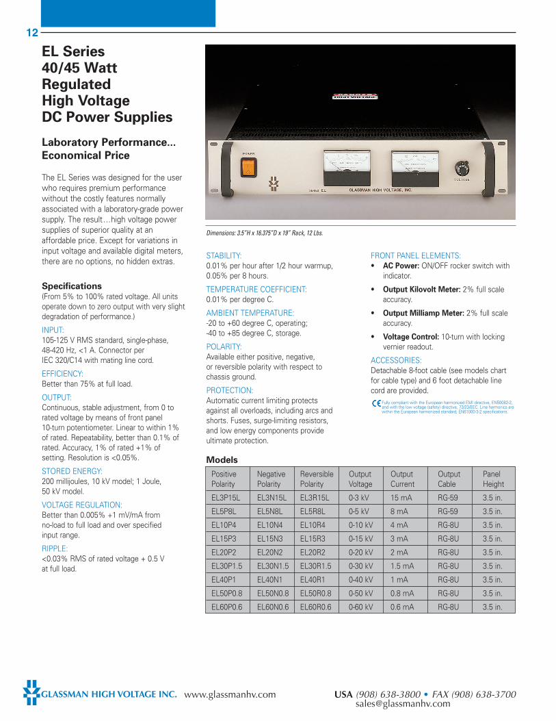
EL Series40/45 WattRegulated High VoltageDC Power Supplies
Laboratory Performance...
Economical Price
The EL Series was designed for the userwho requires premium performancewithout the costly features normallyassociated with a laboratory-grade powersupply. The result ...high voltage powersupplies of superior quality at anaffordable price. Except for variations ininput voltage and available digital meters,there are no options, no hidden extras.
Specifications(From 5% to 100% rated voltage. All unitsoperate down to zero output with very slightdegradation of performance.)
INPUT: 105-125 V RMS standard, single-phase, 48-420 Hz, <1 A. Connector per IEC 320/C14 with mating line cord.
EFFICIENCY: Better than 75% at full load.
OUTPUT:Continuous, stable adjustment, from 0 torated voltage by means of front panel10-turn potentiometer. Linear to within 1%of rated. Repeatability, better than 0.1% ofrated. Accuracy, 1% of rated +1% ofsetting. Resolution is <0.05%.
STORED ENERGY: 200 millijoules, 10 kV model; 1 Joule, 50 kV model.
VOLTAGE REGULATION: Better than 0.005% +1 mV/mA fromno-load to full load and over specifiedinput range.
RIPPLE: <0.03% RMS of rated voltage + 0.5 V at full load.
STABILITY:0.01% per hour after 1/2 hour warmup,0.05% per 8 hours.
TEMPERATURE COEFFICIENT: 0.01% per degree C.
AMBIENT TEMPERATURE: -20 to +60 degree C, operating;-40 to +85 degree C, storage.
POLARITY: Available either positive, negative, or reversible polarity with respect to chassis ground.
PROTECTION: Automatic current limiting protects against all overloads, including arcs andshorts. Fuses, surge-limiting resistors,and low energy components provideultimate protection.
FRONT PANEL ELEMENTS: • AC Power: ON/OFF rocker switch with
indicator.
• Output Kilovolt Meter: 2% full scaleaccuracy.
• Output Milliamp Meter: 2% full scaleaccuracy.
• Voltage Control: 10-turn with lockingvernier readout.
ACCESSORIES: Detachable 8-foot cable (see models chartfor cable type) and 6 foot detachable linecord are provided.
Fully compliant with the European harmonized EMI directive, EN50082-2,and with the low voltage (safety) directive, 73/23/EEC. Line harmonics arewithin the European harmonized standard, EN61000-3-2 specifications.
Positive Negative Reversible Output Output Output PanelPolarity Polarity Polarity Voltage Current Cable Height
EL3P15L EL3N15L EL3R15L 0-3 kV 15 mA RG-59 3.5 in.
EL5P8L EL5N8L EL5R8L 0-5 kV 8 mA RG-59 3.5 in.
EL10P4 EL10N4 EL10R4 0-10 kV 4 mA RG-8U 3.5 in.
EL15P3 EL15N3 EL15R3 0-15 kV 3 mA RG-8U 3.5 in.
EL20P2 EL20N2 EL20R2 0-20 kV 2 mA RG-8U 3.5 in.
EL30P1.5 EL30N1.5 EL30R1.5 0-30 kV 1.5 mA RG-8U 3.5 in.
EL40P1 EL40N1 EL40R1 0-40 kV 1 mA RG-8U 3.5 in.
EL50P0.8 EL50N0.8 EL50R0.8 0-50 kV 0.8 mA RG-8U 3.5 in.
EL60P0.6 EL60N0.6 EL60R0.6 0-60 kV 0.6 mA RG-8U 3.5 in.
Models
Dimensions: 3.5”H x 16.375”D x 19” Rack, 12 Lbs.
13
EUROPE (UK) (1256) 883007 • FAX (1256) 883017 JAPAN (045) 902-9988 • FAX (045) [email protected] [email protected]
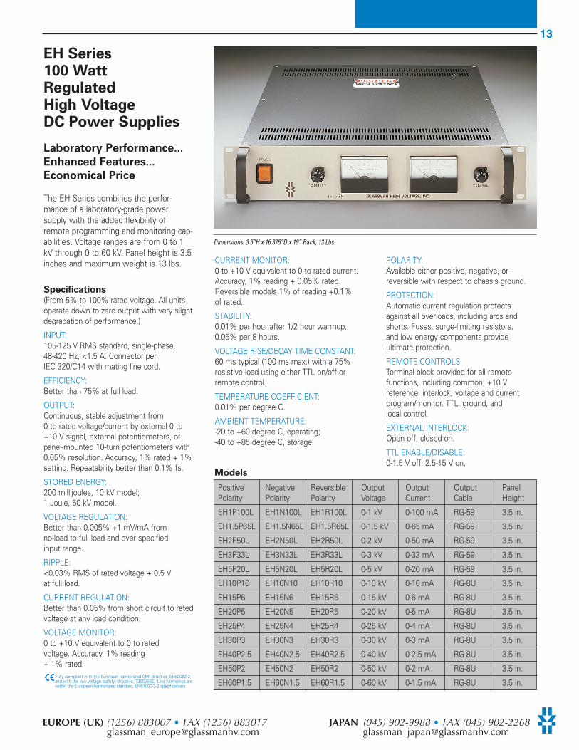
EH Series100 WattRegulatedHigh VoltageDC Power Supplies
Laboratory Performance...
Enhanced Features...
Economical Price
The EH Series combines the perfor-mance of a laboratory-grade powersupply with the added flexibility ofremote programming and monitoring cap-abilities. Voltage ranges are from 0 to 1kV through 0 to 60 kV. Panel height is 3.5inches and maximum weight is 13 lbs.
Specifications(From 5% to 100% rated voltage. All unitsoperate down to zero output with very slightdegradation of performance.)
INPUT: 105-125 V RMS standard, single-phase, 48-420 Hz, <1.5 A. Connector per IEC 320/C14 with mating line cord.
EFFICIENCY:Better than 75% at full load.
OUTPUT:Continuous, stable adjustment from0 to rated voltage/current by external 0 to+10 V signal, external potentiometers, orpanel-mounted 10-turn potentiometers with0.05% resolution. Accuracy, 1% rated + 1%setting. Repeatability better than 0.1% fs.
STORED ENERGY: 200 millijoules, 10 kV model;1 Joule, 50 kV model.
VOLTAGE REGULATION: Better than 0.005% +1 mV/mA fromno-load to full load and over specifiedinput range.
RIPPLE: <0.03% RMS of rated voltage + 0.5 V at full load.
CURRENT REGULATION: Better than 0.05% from short circuit to ratedvoltage at any load condition.
VOLTAGE MONITOR: 0 to +10 V equivalent to 0 to ratedvoltage. Accuracy, 1% reading+ 1% rated.
Fully compliant with the European harmonized EMI directive, EN50082-2,and with the low voltage (safety) directive, 73/23/EEC. Line harmonics arewithin the European harmonized standard, EN61000-3-2 specifications.
CURRENT MONITOR: 0 to +10 V equivalent to 0 to rated current.Accuracy, 1% reading + 0.05% rated.Reversible models 1% of reading +0.1%of rated.
STABILITY: 0.01% per hour after 1/2 hour warmup,0.05% per 8 hours.
VOLTAGE RISE/DECAY TIME CONSTANT: 60 ms typical (100 ms max.) with a 75%resistive load using either TTL on/off orremote control.
TEMPERATURE COEFFICIENT: 0.01% per degree C.
AMBIENT TEMPERATURE: -20 to +60 degree C, operating;-40 to +85 degree C, storage.
POLARITY: Available either positive, negative, orreversible with respect to chassis ground.
PROTECTION: Automatic current regulation protects against all overloads, including arcs andshorts. Fuses, surge-limiting resistors, and low energy components provideultimate protection.
REMOTE CONTROLS: Terminal block provided for all remotefunctions, including common, +10 Vreference, interlock, voltage and currentprogram/monitor, TTL, ground, andlocal control.
EXTERNAL INTERLOCK: Open off, closed on.
TTL ENABLE/DISABLE: 0-1.5 V off, 2.5-15 V on.
Models
Positive Negative Reversible Output Output Output PanelPolarity Polarity Polarity Voltage Current Cable Height
EH1P100L EH1N100L EH1R100L 0-1 kV 0-100 mA RG-59 3.5 in.
EH1.5P65L EH1.5N65L EH1.5R65L 0-1.5 kV 0-65 mA RG-59 3.5 in.
EH2P50L EH2N50L EH2R50L 0-2 kV 0-50 mA RG-59 3.5 in.
EH3P33L EH3N33L EH3R33L 0-3 kV 0-33 mA RG-59 3.5 in.
EH5P20L EH5N20L EH5R20L 0-5 kV 0-20 mA RG-59 3.5 in.
EH10P10 EH10N10 EH10R10 0-10 kV 0-10 mA RG-8U 3.5 in.
EH15P6 EH15N6 EH15R6 0-15 kV 0-6 mA RG-8U 3.5 in.
EH20P5 EH20N5 EH20R5 0-20 kV 0-5 mA RG-8U 3.5 in.
EH25P4 EH25N4 EH25R4 0-25 kV 0-4 mA RG-8U 3.5 in.
EH30P3 EH30N3 EH30R3 0-30 kV 0-3 mA RG-8U 3.5 in.
EH40P2.5 EH40N2.5 EH40R2.5 0-40 kV 0-2.5 mA RG-8U 3.5 in.
EH50P2 EH50N2 EH50R2 0-50 kV 0-2 mA RG-8U 3.5 in.
EH60P1.5 EH60N1.5 EH60R1.5 0-60 kV 0-1.5 mA RG-8U 3.5 in.
Dimensions: 3.5”H x 16.375”D x 19” Rack, 13 Lbs.

14
GLASSMAN HIGH VOLTAGE INC. www.glassmanhv.com USA (908) 638-3800 • FAX (908) [email protected]
FC Series120 WattRegulatedHigh VoltageDC Power Supplies
1 to 60 kV, 1.75" Panel
CE Compliant
The FC Series are sophisticated, 120 Watt,high voltage power supplies in a small andlightweight package. They are air insulated,fast response units, with tight regulation.
The FC Series are fully compliant with theEuropean Harmonized EMI DirectiveEN50082-2 including standards EN55011(Group 1, Class B), ENV50140, ENV50141,ENV50204, EN61000-4-2, and EN61000-4-4.The series are also designed to meet allapplicable standards of the proposedEuropean Low Voltage Safety Directive,73/23/EEC, based on IEC 1010-1.
Specifications(From 5% to 100% rated voltage. All unitsoperate down to zero output with very slightdegradation of performance.)
INPUT: 103-132V RMS standard, single-phase,48-420 Hz, <2.5A at 105V. Connector perIEC 320/VI with mating line cord terminatedwith NEMA 5-15 plug.
EFFICIENCY:Typically 80% at full load.
OUTPUT:Continuous, stable adjustment from 0 torated voltage/current by external 0 to +10 Vsignal, external potentiometers, or panel-mounted 10-turn potentiometers with 0.05%resolution. Accuracy, 0.1% rated + 0.5%setting. Repeatability better than 0.1%of rated.
STORED ENERGY:See Models chart.
STATIC VOLTAGE REGULATION:Better than 0.005% for specified linevariations and 0.005% + 0.5 mV/mA forload variations.
DYNAMIC VOLTAGE REGULATIONFor load transients from 10% to 100% and100% to 10%, typical deviation is 2% ofoutput voltage with recovery to within 1% in500 µs and to 0.1% in 1 ms.
RIPPLE:<0.02% of rated voltage + 300 mV RMSat full load.
CURRENT REGULATION:Better than 0.05% from short circuit to ratedvoltage at any load condition.
VOLTAGE MONITOR0 to +10 V equivalent to 0 to rated voltage.Accuracy, 0.1% reading + 0.5% rated.
CURRENT MONITOR:0 to +10 V equivalent to 0 to rated current.Accuracy, 0.1% of reading +0.5% rated.
STABILITY:0.01% per hour after 1/2 hour warmup,0.05% per 8 hours.
VOLTAGE RISE/DECAY TIME CONSTANT:400 ms typical with a 10% resistive loadusing either TTL on/off or remote program-ming control.
TEMPERATURE COEFFICIENT:0.01% per degree C.
AMBIENT TEMPERATURE:-20 to +50 degree C, operating; -40 to +85 degree C, storage.
POLARITY:Available with either positive, negative,or reversible polarity with respect tochassis ground.
PROTECTION:Automatic current regulation protects againstall overloads, including arcs and shorts. Fuses,surge-limiting resistors,and low energycomponents provide ultimate protection.
REMOTE CONTROLS:A five position terminal block and a 15 Pin“D” connector are provided for all remotefunctions, including common, +10 Vreference, interlock, voltage and currentprogram/monitor, HV enable, ground, andlocal control. A rear panel toggle switchselects either local or remote operation.
EXTERNAL INTERLOCK:Open off, closed on. Normally latching exceptfor blank panel version where it is non-latching.
REMOTE HV ENABLE:0-1.5V off, 2.5-15V on.
ACCESSORIES:Detachable 8 foot shielded high voltagecoaxial cable (see models chart for wiretype), 6 foot detachable line cord and mating15 Pin “D” connector and shell are provided.
Positive Negative Reversible Output Output Stored OutputPolarity Polarity Polarity Voltage Current Energy Cable
FC1P120 FC1N120 FC1R120 0-1kV 0-120mA 0.2J RG-58
FC1.5P80 FC1.5N80 FC1.5R80 0-1.5kV 0-80mA 0.45J RG-58
FC2P60 FC2N60 FC2R60 0-2kV 0-60mA 0.1J RG-58
FC3P40 FC3N40 FC3R40 0-3kV 0-40mA 0.2J RG-58
FC5P24 FC5N24 FC5R24 0-5kV 0-24mA 0.3J RG-58
FC6P20 FC6N20 FC6R20 0-6kV 0-20mA 0.25J RG-8U
FC8P15 FC8N15 FC8R15 0-8kV 0-15mA 0.3J RG-8U
FC10P12 FC10N12 FC10R12 0-10kV 0-12mA 0.4J RG-8U
FC12P10 FC12N10 FC12R10 0-12kV 0-10mA 0.7J RG-8U
FC15P8 FC15N8 FC15R8 0-15kV 0-8mA 1.1J RG-8U
FC20P6 FC20N6 FC20R6 0-20kV 0-6mA 0.85J RG-8U
FC25P4.8 FC25N4.8 FC25R4.8 0-25kV 0-4.8mA 1J RG-8U
FC30P4 FC30N4 FC30R4 0-30kV 0-4mA 1J RG-8U
FC40P3 FC40N3 FC40R3 0-40kV 0-3mA 1.5J RG-8U
FC50P2.4 FC50N2.4 FC50R2.4 0-50kV 0-2.4mA 2J RG-8U
FC60P2 FC60N2 FC60R2 0-60kV 0-2mA 2.4J RG-8U
Models
Dimensions: 1.75”H x 20.25”D x 19” Rack, 12 Lbs.
15
EUROPE (UK) (1256) 883007 • FAX (1256) 883017 JAPAN (045) 902-9988 • FAX (045) [email protected] [email protected]
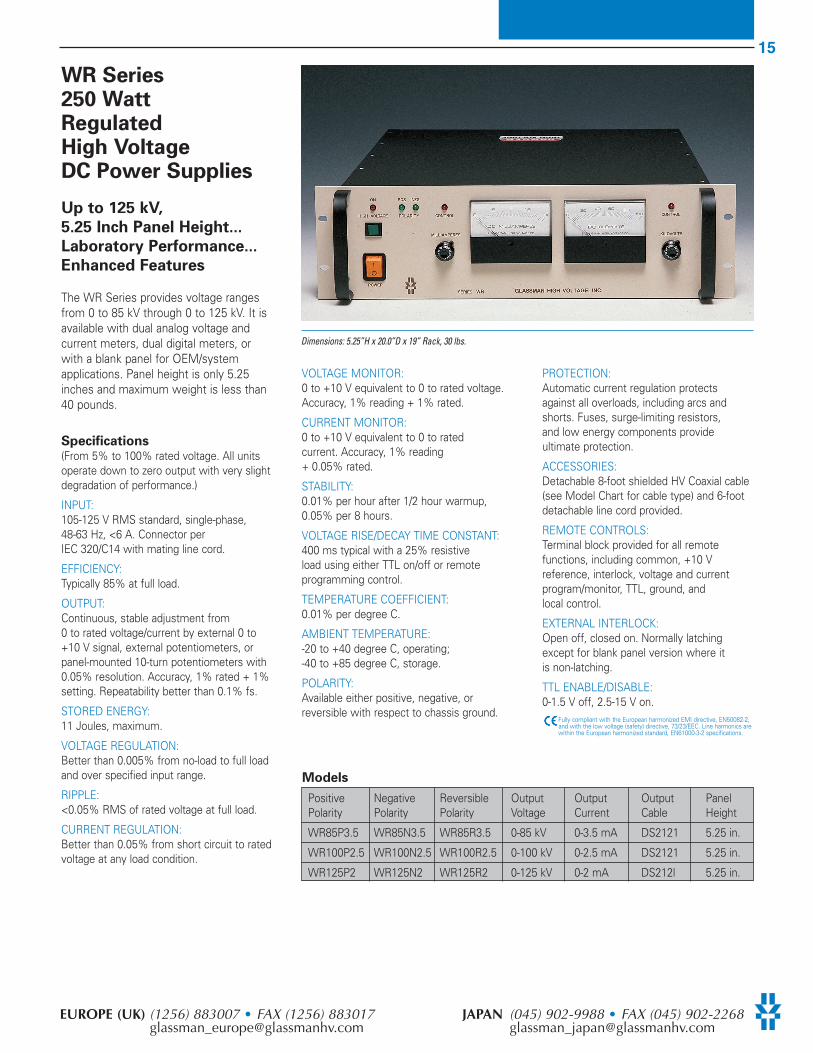
WR Series250 WattRegulatedHigh VoltageDC Power Supplies
Up to 125 kV,
5.25 Inch Panel Height...
Laboratory Performance...
Enhanced Features
The WR Series provides voltage rangesfrom 0 to 85 kV through 0 to 125 kV. It isavailable with dual analog voltage andcurrent meters, dual digital meters, orwith a blank panel for OEM/systemapplications. Panel height is only 5.25inches and maximum weight is less than40 pounds.
Specifications(From 5% to 100% rated voltage. All unitsoperate down to zero output with very slightdegradation of performance.)
INPUT: 105-125 V RMS standard, single-phase, 48-63 Hz, <6 A. Connector per IEC 320/C14 with mating line cord.
EFFICIENCY: Typically 85% at full load.
OUTPUT: Continuous, stable adjustment from0 to rated voltage/current by external 0 to+10 V signal, external potentiometers, orpanel-mounted 10-turn potentiometers with0.05% resolution. Accuracy, 1% rated + 1%setting. Repeatability better than 0.1% fs.
STORED ENERGY: 11 Joules, maximum.
VOLTAGE REGULATION:Better than 0.005% from no-load to full loadand over specified input range.
RIPPLE: <0.05% RMS of rated voltage at full load.
CURRENT REGULATION: Better than 0.05% from short circuit to ratedvoltage at any load condition.
VOLTAGE MONITOR: 0 to +10 V equivalent to 0 to rated voltage.Accuracy, 1% reading + 1% rated.
CURRENT MONITOR: 0 to +10 V equivalent to 0 to ratedcurrent. Accuracy, 1% reading+ 0.05% rated.
STABILITY: 0.01% per hour after 1/2 hour warmup,0.05% per 8 hours.
VOLTAGE RISE/DECAY TIME CONSTANT: 400 ms typical with a 25% resistiveload using either TTL on/off or remoteprogramming control.
TEMPERATURE COEFFICIENT:0.01% per degree C.
AMBIENT TEMPERATURE:-20 to +40 degree C, operating;-40 to +85 degree C, storage.
POLARITY: Available either positive, negative, orreversible with respect to chassis ground.
PROTECTION: Automatic current regulation protects against all overloads, including arcs andshorts. Fuses, surge-limiting resistors, and low energy components provideultimate protection.
ACCESSORIES:Detachable 8-foot shielded HV Coaxial cable(see Model Chart for cable type) and 6-footdetachable line cord provided.
REMOTE CONTROLS:Terminal block provided for all remotefunctions, including common, +10 Vreference, interlock, voltage and currentprogram/monitor, TTL, ground, andlocal control.
EXTERNAL INTERLOCK: Open off, closed on. Normally latchingexcept for blank panel version where it is non-latching.
TTL ENABLE/DISABLE: 0-1.5 V off, 2.5-15 V on.
Fully compliant with the European harmonized EMI directive, EN50082-2,and with the low voltage (safety) directive, 73/23/EEC. Line harmonics arewithin the European harmonized standard, EN61000-3-2 specifications.
Positive Negative Reversible Output Output Output PanelPolarity Polarity Polarity Voltage Current Cable Height
WR85P3.5 WR85N3.5 WR85R3.5 0-85 kV 0-3.5 mA DS2121 5.25 in.
WR100P2.5 WR100N2.5 WR100R2.5 0-100 kV 0-2.5 mA DS2121 5.25 in.
WR125P2 WR125N2 WR125R2 0-125 kV 0-2 mA DS212l 5.25 in.
Models
Dimensions: 5.25”H x 20.0”D x 19” Rack, 30 lbs.
16
GLASSMAN HIGH VOLTAGE INC. www.glassmanhv.com USA (908) 638-3800 • FAX (908) [email protected]
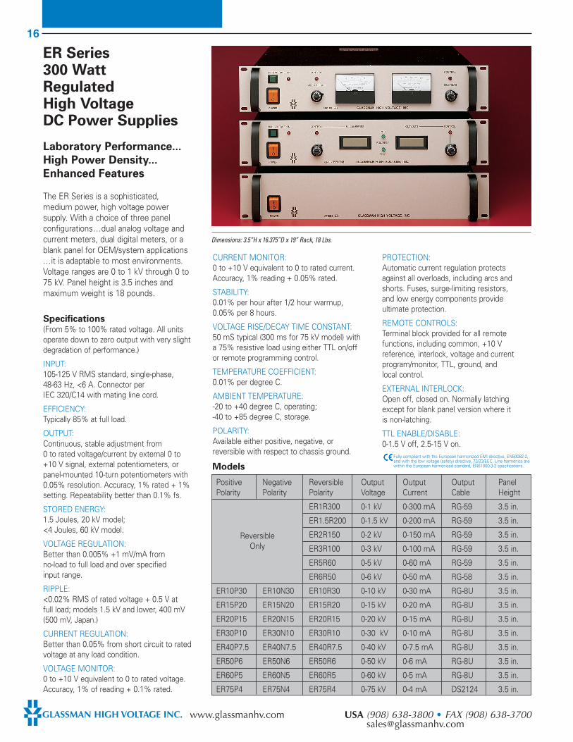
ER Series300 WattRegulatedHigh VoltageDC Power Supplies
Laboratory Performance...
High Power Density...
Enhanced Features
The ER Series is a sophisticated,medium power, high voltage powersupply. With a choice of three panelconfigurations...dual analog voltage andcurrent meters, dual digital meters, or ablank panel for OEM/system applications...it is adaptable to most environments.Voltage ranges are 0 to 1 kV through 0 to75 kV. Panel height is 3.5 inches andmaximum weight is 18 pounds.
Specifications(From 5% to 100% rated voltage. All unitsoperate down to zero output with very slightdegradation of performance.)
INPUT: 105-125 V RMS standard, single-phase, 48-63 Hz, <6 A. Connector per IEC 320/C14 with mating line cord.
EFFICIENCY:Typically 85% at full load.
OUTPUT:Continuous, stable adjustment from0 to rated voltage/current by external 0 to+10 V signal, external potentiometers, orpanel-mounted 10-turn potentiometers with0.05% resolution. Accuracy, 1% rated + 1%setting. Repeatability better than 0.1% fs.
STORED ENERGY: 1.5 Joules, 20 kV model;<4 Joules, 60 kV model.
VOLTAGE REGULATION: Better than 0.005% +1 mV/mA fromno-load to full load and over specifiedinput range.
RIPPLE: <0.02% RMS of rated voltage + 0.5 V at full load; models 1.5 kV and lower, 400 mV (500 mV, Japan.)
CURRENT REGULATION: Better than 0.05% from short circuit to ratedvoltage at any load condition.
VOLTAGE MONITOR: 0 to +10 V equivalent to 0 to rated voltage.Accuracy, 1% of reading + 0.1% rated.
CURRENT MONITOR:0 to +10 V equivalent to 0 to rated current.Accuracy, 1% reading + 0.05% rated.
STABILITY: 0.01% per hour after 1/2 hour warmup,0.05% per 8 hours.
VOLTAGE RISE/DECAY TIME CONSTANT: 50 mS typical (300 ms for 75 kV model) witha 75% resistive load using either TTL on/offor remote programming control.
TEMPERATURE COEFFICIENT: 0.01% per degree C.
AMBIENT TEMPERATURE: -20 to +40 degree C, operating;-40 to +85 degree C, storage.
POLARITY: Available either positive, negative, orreversible with respect to chassis ground.
PROTECTION: Automatic current regulation protects against all overloads, including arcs andshorts. Fuses, surge-limiting resistors, and low energy components provide ultimate protection.
REMOTE CONTROLS: Terminal block provided for all remotefunctions, including common, +10 Vreference, interlock, voltage and currentprogram/monitor, TTL, ground, andlocal control.
EXTERNAL INTERLOCK: Open off, closed on. Normally latching except for blank panel version where it is non-latching.
TTL ENABLE/DISABLE: 0-1.5 V off, 2.5-15 V on.
Fully compliant with the European harmonized EMI directive, EN50082-2,and with the low voltage (safety) directive, 73/23/EEC. Line harmonics arewithin the European harmonized standard, EN61000-3-2 specifications.
Positive Negative Reversible Output Output Output PanelPolarity Polarity Polarity Voltage Current Cable Height
ER1R300 0-1 kV 0-300 mA RG-59 3.5 in.
ER1.5R200 0-1.5 kV 0-200 mA RG-59 3.5 in.
ER2R150 0-2 kV 0-150 mA RG-59 3.5 in.
ER3R100 0-3 kV 0-100 mA RG-59 3.5 in.
ER5R60 0-5 kV 0-60 mA RG-59 3.5 in.
ER6R50 0-6 kV 0-50 mA RG-58 3.5 in.
ER10P30 ER10N30 ER10R30 0-10 kV 0-30 mA RG-8U 3.5 in.
ER15P20 ER15N20 ER15R20 0-15 kV 0-20 mA RG-8U 3.5 in.
ER20P15 ER20N15 ER20R15 0-20 kV 0-15 mA RG-8U 3.5 in.
ER30P10 ER30N10 ER30R10 0-30 kV 0-10 mA RG-8U 3.5 in.
ER40P7.5 ER40N7.5 ER40R7.5 0-40 kV 0-7.5 mA RG-8U 3.5 in.
ER50P6 ER50N6 ER50R6 0-50 kV 0-6 mA RG-8U 3.5 in.
ER60P5 ER60N5 ER60R5 0-60 kV 0-5 mA RG-8U 3.5 in.
ER75P4 ER75N4 ER75R4 0-75 kV 0-4 mA DS2124 3.5 in.
Models
ReversibleOnly
Dimensions: 3.5”H x 16.375”D x 19” Rack, 18 Lbs.
17
EUROPE (UK) (1256) 883007 • FAX (1256) 883017 JAPAN (045) 902-9988 • FAX (045) [email protected] [email protected]
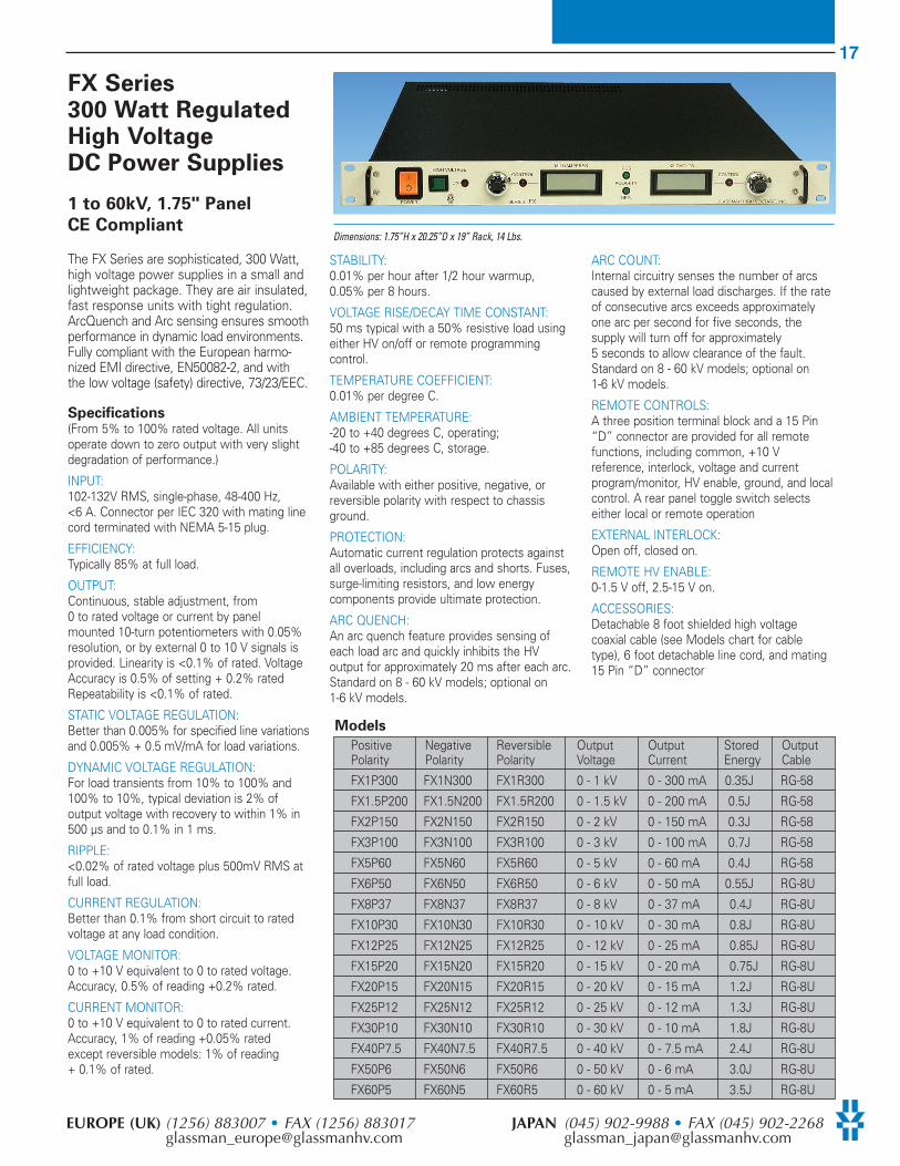
FX Series300 Watt Regulated High VoltageDC Power Supplies
1 to 60kV, 1.75" Panel
CE Compliant
The FX Series are sophisticated, 300 Watt,high voltage power supplies in a small andlightweight package. They are air insulated,fast response units with tight regulation.ArcQuench and Arc sensing ensures smoothperformance in dynamic load environments.Fully compliant with the European harmo-nized EMI directive, EN50082-2, and withthe low voltage (safety) directive, 73/23/EEC.
Specifications(From 5% to 100% rated voltage. All unitsoperate down to zero output with very slightdegradation of performance.)
INPUT: 102-132V RMS, single-phase, 48-400 Hz,<6 A. Connector per IEC 320 with mating linecord terminated with NEMA 5-15 plug.
EFFICIENCY: Typically 85% at full load.
OUTPUT: Continuous, stable adjustment, from0 to rated voltage or current by panelmounted 10-turn potentiometers with 0.05%resolution, or by external 0 to 10 V signals isprovided. Linearity is <0.1% of rated. VoltageAccuracy is 0.5% of setting + 0.2% ratedRepeatability is <0.1% of rated.
STATIC VOLTAGE REGULATION: Better than 0.005% for specified line variationsand 0.005% + 0.5 mV/mA for load variations.
DYNAMIC VOLTAGE REGULATION: For load transients from 10% to 100% and100% to 10%, typical deviation is 2% ofoutput voltage with recovery to within 1% in500 µs and to 0.1% in 1 ms.
RIPPLE: <0.02% of rated voltage plus 500mV RMS atfull load.
CURRENT REGULATION: Better than 0.1% from short circuit to ratedvoltage at any load condition.
VOLTAGE MONITOR: 0 to +10 V equivalent to 0 to rated voltage.Accuracy, 0.5% of reading +0.2% rated.
CURRENT MONITOR: 0 to +10 V equivalent to 0 to rated current.Accuracy, 1% of reading +0.05% rated except reversible models: 1% of reading+ 0.1% of rated.
STABILITY: 0.01% per hour after 1/2 hour warmup,0.05% per 8 hours.
VOLTAGE RISE/DECAY TIME CONSTANT: 50 ms typical with a 50% resistive load usingeither HV on/off or remote programmingcontrol.
TEMPERATURE COEFFICIENT: 0.01% per degree C.
AMBIENT TEMPERATURE: -20 to +40 degrees C, operating; -40 to +85 degrees C, storage.
POLARITY: Available with either positive, negative, orreversible polarity with respect to chassisground.
PROTECTION: Automatic current regulation protects againstall overloads, including arcs and shorts. Fuses,surge-limiting resistors, and low energycomponents provide ultimate protection.
ARC QUENCH: An arc quench feature provides sensing ofeach load arc and quickly inhibits the HVoutput for approximately 20 ms after each arc.Standard on 8 - 60 kV models; optional on1-6 kV models.
ARC COUNT: Internal circuitry senses the number of arcscaused by external load discharges. If the rateof consecutive arcs exceeds approximatelyone arc per second for five seconds, thesupply will turn off for approximately5 seconds to allow clearance of the fault.Standard on 8 - 60 kV models; optional on1-6 kV models.
REMOTE CONTROLS: A three position terminal block and a 15 Pin“D” connector are provided for all remotefunctions, including common, +10 Vreference, interlock, voltage and currentprogram/monitor, HV enable, ground, and localcontrol. A rear panel toggle switch selectseither local or remote operation
EXTERNAL INTERLOCK: Open off, closed on.
REMOTE HV ENABLE: 0-1.5 V off, 2.5-15 V on.
ACCESSORIES: Detachable 8 foot shielded high voltagecoaxial cable (see Models chart for cabletype), 6 foot detachable line cord, and mating15 Pin “D” connector
Models
Positive Negative Reversible Output Output Stored OutputPolarity Polarity Polarity Voltage Current Energy Cable
FX1P300 FX1N300 FX1R300 0 - 1 kV 0 - 300 mA 0.35J RG-58
FX1.5P200 FX1.5N200 FX1.5R200 0 - 1.5 kV 0 - 200 mA 0.5J RG-58
FX2P150 FX2N150 FX2R150 0 - 2 kV 0 - 150 mA 0.3J RG-58
FX3P100 FX3N100 FX3R100 0 - 3 kV 0 - 100 mA 0.7J RG-58
FX5P60 FX5N60 FX5R60 0 - 5 kV 0 - 60 mA 0.4J RG-58
FX6P50 FX6N50 FX6R50 0 - 6 kV 0 - 50 mA 0.55J RG-8U
FX8P37 FX8N37 FX8R37 0 - 8 kV 0 - 37 mA 0.4J RG-8U
FX10P30 FX10N30 FX10R30 0 - 10 kV 0 - 30 mA 0.8J RG-8U
FX12P25 FX12N25 FX12R25 0 - 12 kV 0 - 25 mA 0.85J RG-8U
FX15P20 FX15N20 FX15R20 0 - 15 kV 0 - 20 mA 0.75J RG-8U
FX20P15 FX20N15 FX20R15 0 - 20 kV 0 - 15 mA 1.2J RG-8U
FX25P12 FX25N12 FX25R12 0 - 25 kV 0 - 12 mA 1.3J RG-8U
FX30P10 FX30N10 FX30R10 0 - 30 kV 0 - 10 mA 1.8J RG-8U
FX40P7.5 FX40N7.5 FX40R7.5 0 - 40 kV 0 - 7.5 mA 2.4J RG-8U
FX50P6 FX50N6 FX50R6 0 - 50 kV 0 - 6 mA 3.0J RG-8U
FX60P5 FX60N5 FX60R5 0 - 60 kV 0 - 5 mA 3.5J RG-8U
Dimensions: 1.75”H x 20.25”D x 19” Rack, 14 Lbs.

18
GLASSMAN HIGH VOLTAGE INC. www.glassmanhv.com USA (908) 638-3800 • FAX (908) [email protected]
EW SeriesExtended Current500 Watt RegulatedHigh VoltageDC Power Supplies
Up to 60 kV,
3.5 Inch Panel Height...
Laboratory Performance...
Enhanced Features
The EW Series is a 500 watt regulated highvoltage DC power supply with an importantdifference...maximum current ratings areequivalent to a 600 W supply! Thismaximum current, which is available for alloutput voltages up to 84% of rated voltage,should be of significant interest for manyapplications. Voltage ranges are 0 to 1 kVthrough 0 to 60 kV.
Specifications(From 5% to 100% rated voltage. All unitsoperate down to zero output with very slightdegradation of performance.)
INPUT: 102-132 V RMS standard, single-phase,48-63 Hz, <10 A. Connector per IEC 320/C14with mating line cord, terminated withNEMA 5-15 plug.
EFFICIENCY: Typically 85% at full load.
OUTPUT: Continuous, stable adjustment from0 to rated voltage/current by external 0 to+10 V signal, external potentiometers, orpanel-mounted 10-turn potentiometers with0.05% resolution. Accuracy, 1% rated + 1%setting. Repeatability better than 0.1% fs.
STORED ENERGY: <1.5 Joules, 20 kV; <4 Joules, 60 kV.
VOLTAGE REGULATION: Better than 0.005% for specified linevariations and 0.005% + 1 mV/mA for load variations.
RIPPLE:<0.02% of rated voltage + 0.5 V RMS at full load.
CURRENT REGULATION: Better than 0.05% from short circuit to ratedvoltage at any load condition.
VOLTAGE MONITOR: 0 to +10 V equivalent to 0 to rated voltage.Accuracy, 1% reading + 1% rated.
CURRENT MONITOR: 0 to +10 V equivalent to 0 to rated current.Accuracy, 1% reading + 0.05% rated forsingle polarity, 1% reading + 0.1% rated forreversible polarity.
STABILITY:0.01% per hour after 1/2 hour warmup,0.05% per 8 hours.
VOLTAGE RISE/DECAY TIME CONSTANT: 50 ms typical with a 30% resistive load using either TTL on/off or remoteprogramming control.
TEMPERATURE COEFFICIENT: 0.01% per degree C.
AMBIENT TEMPERATURE: -20 to +40 degree C, operating;-40 to +85 degree C, storage.
POLARITY: Available either positive, negative, orreversible with respect to chassis ground.
PROTECTION: Automatic current regulation protects against all overloads, including arcs andshorts. Fuses, surge-limiting resistors, and low energy components provideultimate protection.
REMOTE CONTROLS: Terminal block provided for all remotefunctions, including common, +10 Vreference, interlock, voltage and currentprogram/monitor, TTL, ground, and local control.
EXTERNAL INTERLOCK: Open off, closed on. Normally latching except for blank panel version where it is non-latching.
TTL ENABLE/DISABLE: 0-1.5 V off, 2.5-15 V on.
Fully compliant with the European harmonized EMI directive, EN50082-2,and with the low voltage (safety) directive, 73/23/EEC. Line harmonics arewithin the European harmonized standard, EN61000-3-2 specifications.
Positive Negative Reversible Output Output Output PanelPolarity Polarity Polarity Voltage Current Cable Height
EW1R600 0-1 kV 0-600 mA RG-59 3.5 in.
EW1.5R400 0-1.5 kV 0-400 mA RG-59 3.5 in.
EW2R300 0-2 kV 0-300 mA RG-59 3.5 in.
EW3R200 0-3 kV 0-200 mA RG-59 3.5 in.
EW5R120 0-5 kV 0-120 mA RG-59 3.5 in.
EW7P85 EW7N85 EW7R85 0-7 kV 0-85 mA RG-8U 3.5 in.
EW10P60 EW10N60 EW10R60 0-10 kV 0-60 mA RG-8U 3.5 in.
EW15P40 EW15N40 EW15R40 0-15 kV 0-40 mA RG-8U 3.5 in.
EW20P30 EW20N30 EW20R30 0-20 kV 0-30 mA RG-8U 3.5 in.
EW25P24 EW25N24 EW25R24 0-25 kV 0-24 mA RG-8U 3.5 in.
EW30P20 EW30N20 EW30R20 0-30 kV 0-20 mA RG-8U 3.5 in.
EW40P15 EW40N15 EW40R15 0-40 kV 0-15 mA RG-8U 3.5 in.
EW50P12 EW50N12 EW50R12 0-50 kV 0-12 mA RG-8U 3.5 in.
EW60P10 EW60N10 EW60R10 0-60 kV 0-10 mA RG-8U 3.5 in.
Models
Note: Product of voltage and current automatically limited to 500 W maximum.
ReversibleOnly
Dimensions: 3.5”H x 16.375”D x 19” Rack, 18 Lbs.

19
EUROPE (UK) (1256) 883007 • FAX (1256) 883017 JAPAN (045) 902-9988 • FAX (045) [email protected] [email protected]
WK SeriesExtended Current500 WattRegulatedHigh VoltageDC Power Supplies
Up To 125 kV...
5.25 Inch Panel Height...
Laboratory Performance...
Enhanced Features
The WK Series is a 500 watt regulatedDC power supply offering output voltageranges from 80 kV to 125 kV and aninteresting “plus.” Maximum currentratings are equivalent to a 600 W supplyup to 84% of rated voltage! Panel heightis only 5.25 inches and weight is less than30 pounds. The WK Series is availablewith dual analog output meters or,optionally, with digital meters or a blankpanel for OEM/ system applications.
Specifications(From 5% to 100% rated voltage. All unitsoperate down to zero output with very slightdegradation of performance.)
INPUT: 102-132V RMS, 48-63 Hz single phase, <10 A. Connector per IEC 320/Vl withmating line cord and NEMA 5-15 plug.
EFFICIENCY: Typically 83% at full load.
OUTPUT: Continuous, stable adjustment from zero torated voltage and current via 10-turnpotentiometers, with 0.05% resolution,external 0 to 10 V, or externalpotentiometers. Linearity, <1% fs.Repeatability, <0.1% fs. Accuracy, 0.25% ofrated + 1% of setting.
STORED ENERGY: 9 J, 80 kV; 11 J, 100 kV; 14.5 J, 125 kV.
VOLTAGE REGULATION:<0.005%, line or load.
RIPPLE: <0.1% RMS of rated voltage at full load.
CURRENT REGULATION: <0.1% of full scale from short circuit to rated voltage.
VOLTAGE MONITOR: 0 to +10 V DC for zero to rated voltage.Accuracy, 1% of reading + 1% ofrated voltage.
CURRENT MONITOR: 0 to +10 V DC for zero to rated current.Accuracy, 1% of reading + 0.05% (0.1% for reversible model) of rated current.
STABILITY: 0.01% per hour after 1/2 hour warmup.0.05% per 8 hours.
OUTPUT VOLTAGE TIME CONSTANT:Typically 400 ms rise or decay time constantfor 125 kV model, using TTL on/off orremote voltage control, with 15%resistive load.
TEMPERATURE COEFFICIENT: 0.01%/degree C.
AMBIENT TEMPERATURE: -20 to +40 degrees C, operating;-40 to +85 degrees C, storage.
POLARITY: Positive, negative, or reversible with respectto chassis ground.
PROTECTION:Automatic current regulation protects against all overloads, including arcs andshorts. Fuses, surge-limiting resistors,and low-energy components provideultimate protection.
ACCESSORIES: Detachable 8-foot shielded HV coaxial cable(see Model Chart for cable type) and 6-footdetachable line cord provided.
REMOTE CONTROLS: Terminal block provided for all remotefunctions, including common, +10 Vreference, interlock, voltage and currentprogram/monitor, TTL, ground, andlocal control.
EXTERNAL INTERLOCK: Open off, closed on. Normally latchingexcept on blank panel version where it isnon-latching.
TTL ENABLE/DISABLE: 0-1.5 V off, 2.5-15 V on.
Fully compliant with the European harmonized EMI directive, EN50082-2,and with the low voltage (safety) directive, 73/23/EEC. Line harmonics arewithin the European harmonized standard, EN61000-3-2 specifications.
Positive Negative Reversible Output Output OutputPolarity Polarity Polarity Voltage Current Cable
WK80P7.5 WK80N7.5 WK80R7.5 0-80 kV 0-7.5 mA DS2121
WK100P6 WK100N6 WK100R6 0-100 kV 0-6 mA DS2121
WK125P5 WK125N5 WK125R5 0-125 kV 0-5 mA DS2121Note: Product of voltage and current automatically limited to 500 W maximum.
Models
Dimensions: 5.25”H x 20”D x 19” Rack, 30 lbs.
20
GLASSMAN HIGH VOLTAGE INC. www.glassmanhv.com USA (908) 638-3800 • FAX (908) [email protected]
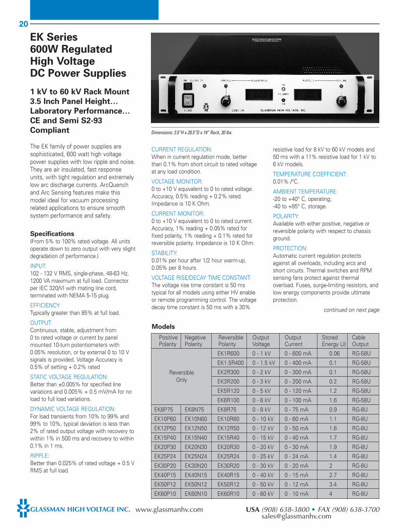
EK Series 600W RegulatedHigh Voltage DC Power Supplies
1 kV to 60 kV Rack Mount
3.5 Inch Panel Height…
Laboratory Performance…
CE and Semi S2-93
Compliant
The EK family of power supplies aresophisticated, 600 watt high voltagepower supplies with low ripple and noise.They are air insulated, fast responseunits, with tight regulation and extremelylow arc discharge currents. ArcQuenchand Arc Sensing features make thismodel ideal for vacuum processingrelated applications to ensure smoothsystem performance and safety.
Specifications(From 5% to 100% rated voltage. All unitsoperate down to zero output with very slightdegradation of performance.)
INPUT: 102 - 132 V RMS, single-phase, 48-63 Hz,1200 VA maximum at full load. Connectorper IEC 320/VI with mating line cord,terminated with NEMA 5-15 plug.
EFFICIENCY: Typically greater than 85% at full load.
OUTPUT: Continuous, stable, adjustment from0 to rated voltage or current by panelmounted 10-turn potentiometers with0.05% resolution, or by external 0 to 10 Vsignals is provided. Voltage Accuracy is0.5% of setting + 0.2% rated
STATIC VOLTAGE REGULATION: Better than ±0.005% for specified linevariations and 0.005% + 0.5 mV/mA for noload to full load variations.
DYNAMIC VOLTAGE REGULATION: For load transients from 10% to 99% and99% to 10%, typical deviation is less than2% of rated output voltage with recovery towithin 1% in 500 ms and recovery to within0.1% in 1 ms.
RIPPLE: Better than 0.025% of rated voltage + 0.5 VRMS at full load.
CURRENT REGULATION: When in current regulation mode, betterthan 0.1% from short circuit to rated voltageat any load condition.
VOLTAGE MONITOR: 0 to +10 V equivalent to 0 to rated voltage.Accuracy, 0.5% reading + 0.2% rated.Impedance is 10 K Ohm.
CURRENT MONITOR: 0 to +10 V equivalent to 0 to rated current.Accuracy, 1% reading + 0.05% rated forfixed polarity, 1% reading + 0.1% rated forreversible polarity. Impedance is 10 K Ohm.
STABILITY: 0.01% per hour after 1/2 hour warm-up,0.05% per 8 hours.
VOLTAGE RISE/DECAY TIME CONSTANT: The voltage rise time constant is 50 mstypical for all models using either HV enableor remote programming control. The voltagedecay time constant is 50 ms with a 30%
resistive load for 8 kV to 60 kV models and50 ms with a 11% resistive load for 1 kV to6 kV models.
TEMPERATURE COEFFICIENT: 0.01% /°C.
AMBIENT TEMPERATURE: -20 to +40° C, operating; -40 to +85° C, storage.
POLARITY: Available with either positive, negative orreversible polarity with respect to chassisground.
PROTECTION: Automatic current regulation protectsagainst all overloads, including arcs andshort circuits. Thermal switches and RPMsensing fans protect against thermaloverload. Fuses, surge-limiting resistors, andlow energy components provide ultimateprotection.
continued on next page
Models
Positive Negative Reversible Output Output Stored CablePolarity Polarity Polarity Voltage Current Energy (J) Output
EK1R600 0 - 1 kV 0 - 600 mA 0.06 RG-58U
EK1.5R400 0 - 1.5 kV 0 - 400 mA 0.1 RG-58U
EK2R300 0 - 2 kV 0 - 300 mA 0.1 RG-58U
EK3R200 0 - 3 kV 0 - 200 mA 0.2 RG-58U
EK5R120 0 - 5 kV 0 - 120 mA 1.2 RG-58U
EK6R100 0 - 6 kV 0 - 100 mA 1.6 RG-58U
EK8P75 EK8N75 EK8R75 0 - 8 kV 0 - 75 mA 0.9 RG-8U
EK10P60 EK10N60 EK10R60 0 - 10 kV 0 - 60 mA 1.1 RG-8U
EK12P50 EK12N50 EK12R50 0 - 12 kV 0 - 50 mA 1.6 RG-8U
EK15P40 EK15N40 EK15R40 0 - 15 kV 0 - 40 mA 1.7 RG-8U
EK20P30 EK20N30 EK20R30 0 - 20 kV 0 - 30 mA 1.9 RG-8U
EK25P24 EK25N24 EK25R24 0 - 25 kV 0 - 24 mA 1.4 RG-8U
EK30P20 EK30N20 EK30R20 0 - 30 kV 0 - 20 mA 2 RG-8U
EK40P15 EK40N15 EK40R15 0 - 40 kV 0 - 15 mA 2.7 RG-8U
EK50P12 EK50N12 EK50R12 0 - 50 kV 0 - 12 mA 3.4 RG-8U
EK60P10 EK60N10 EK60R10 0 - 60 kV 0 - 10 mA 4 RG-8U
ReversibleOnly
Dimensions: 3.5”H x 20.5”D x 19” Rack, 20 lbs.

21
EUROPE (UK) (1256) 883007 • FAX (1256) 883017 JAPAN (045) 902-9988 • FAX (045) [email protected] [email protected]
ARC QUENCH: An arc quench feature provides sensing ofeach load arc and quickly inhibits the HVoutput for approximately 20 ms after eacharc. Standard on 8 - 60 kV models; optionalon 1- 6 kV models.
ARC COUNT: Internal circuitry senses the number of arcscaused by external load discharges. If therate of consecutive arcs exceeds approxi-mately one arc per second for five arcs, thesupply will turn off for approximately5 seconds to allow clearance of the fault.After this period the supply will automaticallyreturn to the programmed kV value with therise time constant indicated. If the load faultstill exists the above cycle will repeat.Standard on 8 - 60 kV models; optional on1 - 6 kV models.
EXTERNAL INTERLOCK: Open = off, closed = on. Normally latchingexcept for blank front panel version where itis non-latching.
FRONT PANEL ELEMENTS:The front panel contains all local controlfunctions. These control functions are: ACpower on/off switch and pilot light, separate10-turn controls with locking vernier dialsused to set voltage and current levels, and ahigh voltage ON switch. LED's indicatewhen high voltage is on, output polarity, andwhether the supply is operating in a voltageor current regulating mode. Output levelsare indicated by voltage and current digitalmeters.
REAR PANEL ELEMENTS:AC power entry connector, fuses, power onindicator, ground stud, HV output connector,and remote interface terminal strip.
The signals provided on the remote interfaceterminal strip are as follows:
• Inputs: Safety interlock, output voltageand current program signals, and highvoltage enable.
• Outputs: Output voltage and currentmonitor signals, and a +10 V referencesource.
Signal common and ground referenceterminals are also provided.
• Remote HV Enable/Disable:
0 - 1.5 V = OFF, 2.5 - 15 V = ON.
ACCESSORIES: Detachable, 8 foot, shielded high voltagecoaxial cable (see models chart for cabletype) and 6 foot detachable line cord areprovided.
Fully compliant with the European harmonized EMI directive, EN50082-2,and with the low voltage (safety) directive, 73/23/EEC. Line harmonics arewithin the European harmonized standard, EN61000-3-2 specifications.

22
GLASSMAN HIGH VOLTAGE INC. www.glassmanhv.com USA (908) 638-3800 • FAX (908) [email protected]
PG Series500/1000 WattRegulatedHigh VoltageDC Power Supplies
PG-LR Series250/500 WattLow RippleRegulatedHigh VoltageDC Power Supplies
100 kV to 400 kV...
The PG Series is available in twoconfigurations ... as a standard PG Seriesor as an ultra-low ripple PG-LR Series fordemanding applications, such as particleaccelerators. Shown is the dual-stackPG-LR Series with remote control unit. Onestack serves as a high voltage multiplierwhile the second stack provides anadditional lowpass ripple filter. Thestandard PG Series is supplied with onlythe multiplier stack and remote control unit.
Specifications(From 5% to 100% rated voltage. All unitsoperate down to zero output with very slightdegradation of performance.)
INPUT: 105-125 V RMS, single-phase, 48-63 Hz,<15 A. Series PG-LR: 208 V RMS+/- 10%, 3-phase, 48-63 Hz, <5 A.
EFFICIENCY: Typically 75% at full load.
OUTPUT: Continuous, stable adjustment from0 to rated voltage and current by meansof front panel 10-turn potentiometers,external zero to +10 V signals, or externalpotentiometers. Linearity to within 1%of full scale.
VOLTAGE REGULATION:Better than 0.005% + 1 V, line or load.
RIPPLE: Better than 0.1% of rated voltage at full load.Series PG-LR: See models chart.
CURRENT REGULATION: Better than 100 µA from short circuit to ratedvoltage for any load condition; 0.005% + 1 µAfor line variations.
VOLTAGE/CURRENT MONITOR:Zero to +10 V signal for zero to ratedvoltage/current.
STABILITY: 0.01% + 1 V per hour after 1/2 hour warmup,0.05% + 2 V per 8 hours.
TEMPERATURE COEFFICIENT: 0.01% per degree C + 1 V.
AMBIENT TEMPERATURE: -20 to +60 degree C, operating;-40 to +85 degree C, non-operating.
POLARITY: Available with either positive, negative, orreversible (PG only) polarity with respect tochassis ground.
PROTECTION: Automatic current regulation protects thepower supply against all overload conditions,including arcs and short circuits. Fuses,surge-limiting resistors, and low energycomponents provide the ultimate protection.
EXTERNAL INTERLOCK: Open off, closed on.
Positive Negative Reversible Output Output Panel StackPolarity Polarity Polarity Voltage Current Height Height
PG100P5 PG100N5 PG100R5 0-100 kV 0-5 mA 5.25 in 22.75 in
PG100P10 PG100N10 PG100R10 0-100 kV 0-10 mA 5.25 in 22.75 in
PG150P3 PG150N3 PG150R3 0-150 kV 0-3 mA 5.25 in 29.75 in
PG150P6 PG150N6 PG150R6 0-150 kV 0-6 mA 5.25 in 29.75 in
PG200P2.5 PG200N2.5 PG200R2.5 0-200 kV 0-2.5 mA 5.25 in 34.75 in
PG200P5 PG200N5 PG200R5 0-200 kV 0-5 mA 5.25 in 34.75 in
PG250P1 PG250N1 PG250R1 0-250 kV 0-1 mA 5.25 in 40.50 in
PG250P2 PG250N2 PG250R2 0-250 kV 0-2 mA 5.25 in 40.50 in
PG300P1 PG300N1 PG300R1 0-300 kV 0-1 mA 5.25 in 50.88 in
PG300P2 PG300N2 PG300R2 0-300 kV 0-2 mA 5.25 in 50.88 in
PG400P1 PG400N1 PG400R1 0-400 kV 0-1 mA 5.25 in 63.25 in
PG Models
PG-LR Models (same panel and stack heights as above)
Positive Negative Output Output Ripple (V p-p)Polarity Polarity Voltage Current Typ. Max.PG100P2.5-LR PG100N2.5-LR 0-100 kV 0-2.5 mA 2 4.5
PG100P5-LR PG100N5-LR 0-100 kV 0-5 mA 4 7
PG150P2-LR PG150N2-LR 0-150 kV 0-2 mA 3 5
PG150P3-LR PG150N3-LR 0-150 kV 0-3 mA 6 9
PG200P1-LR PG200N1-LR 0-200 kV 0-1 mA 3.5 5
PG200P2-LR PG200N2-LR 0-200 kV 0-2 mA 7 10
PG250P1-LR PG250N1-LR 0-250 kV 0-1 mA 4.5 6.5
PG250P2-LR PG250N2-LR 0-250 kV 0-2 mA 8.5 12.5
PG300P1-LR PG300N1-LR 0-300 kV 0-1 mA 5 7.5
PG300P2-LR PG300N2-LR 0-300 kV 0-2 mA 10 15
PG400P1-LR PG400N1-LR 0-400 kV 0-1 mA 7 10

23
EUROPE (UK) (1256) 883007 • FAX (1256) 883017 JAPAN (045) 902-9988 • FAX (045) [email protected] [email protected]
WX Series1000 WattRegulatedHigh VoltageDC Power Supplies
Up to 75 kV,
5.25 Inch Panel Height...
Laboratory Performance...
Enhanced Features
The WX Series provides 1000 watts ofoutput power with voltage ranges from 0to 1 kV through 0 to 75 kV in a rack-panelheight of only 5.25 inches. Standardmodels have dual analog voltage andcurrent meters. As an option, WX isavailable with dual digital meters orwith a blank panel for OEM/systemapplications. Local front panel and fullremote controls are standard. Maximumweight is 30 lbs.
Specifications(From 5% to 100% rated voltage. All unitsoperate down to zero output with very slightdegradation of performance.)
INPUT: 198-242 V RMS standard, single-phase, 48-63 Hz, <9.5 A. Connector per IEC 320/C14 with mating line cord,terminated with NEMA 6-15 plug.
EFFICIENCY: Typically 83% at full load.
OUTPUT: Continuous, stable adjustment from0 to rated voltage/current by external 0 to+10 V signal, external potentiometers, orpanel-mounted 10-turn potentiometers with0.05% resolution. Accuracy, 1% rated + 1%setting. Repeatability better than 0.1% fs.
STORED ENERGY:6 Joules, maximum, up to 50 kV;9 Joules, maximum, 60 and 75 kV.
VOLTAGE REGULATION: Better than 0.005% for specified linevariations and 0.01% + 1 mV/mA for load variations.
RIPPLE: <0.05% of rated voltage + 0.5 V RMS at full load.
CURRENT REGULATION: Better than 0.05% from short circuit to ratedvoltage at any load condition.
VOLTAGE MONITOR: 0 to +10 V equivalent to 0 to rated voltage.Accuracy, 1% reading + 1% rated.
CURRENT MONITOR: 0 to +10 V equivalent to 0 to rated current.Accuracy, 1% reading + 0.05% rated.
STABILITY: 0.01% per hour after 1/2 hour warmup,0.05% per 8 hour.
VOLTAGE RISE/DECAY TIME CONSTANT: 50 ms typical with a 50% resistive load using either TTL on/off or remoteprogramming control.
TEMPERATURE COEFFICIENT: 0.01% per degree C.
AMBIENT TEMPERATURE: -20 to +45 degree C, operating;-40 to +85 degree C, storage.
POLARITY: Available either positive, negative, orreversible with respect to chassis ground.
PROTECTION: Automatic current regulation protectsagainst all overloads. including arcs andshorts. Fuses, surge-limiting resistors, andlow energy components provide ultimateprotection.
REMOTE CONTROLS: Terminal blocks provided for all remotefunctions, including common, +10 V refer-ence, interlock, voltage and current program/monitor, TTL, ground, and local control.
EXTERNAL INTERLOCK: Open off, closed on. Normally latchingexcept for blank panel version where it is non-latching.
TTL ENABLE/DISABLE: 0-1.5 V off, 2.5-15 V on.
Fully compliant with the European harmonized EMI directive, EN50082-2,and with the low voltage (safety) directive, 73/23/EEC. Line harmonics arewithin the European harmonized standard, EN61000-3-2 specifications.
Positive Negative Reversible Output Output Output PanelPolarity Polarity Polarity Voltage Current Cable Height
WX1R1000 0-1 kV 0-1000 mA RG-59 5.25 in.
WX1.5R700 0-1.5 kV 0-700 mA RG-59 5.25 in.
WX2R500 0-2 kV 0-500 mA RG-59 5.25 in.
WX3R350 0-3 kV 0-350 mA RG-59 5.25 in.
WX5R200 0-5 kV 0-200 mA RG-59 5.25 in.
WX10P100 WX10N100 WX10R100 0-10 kV 0-100 mA RG-8U 5.25 in.
WX15P70 WX15N70 WX15R70 0-15 kV 0-70 mA RG-8U 5.25 in.
WX20P50 WX20N50 WX20R50 0-20 kV 0-50 mA RG-8U 5.25 in.
WX30P35 WX30N35 WX30R35 0-30 kV 0-35 mA RG-8U 5.25 in.
WX40P25 WX40N25 WX40R25 0-40 kV 0-25 mA RG-8U 5.25 in.
WX50P20 WX50N20 WX50R20 0-50 kV 0-20 mA RG-8U 5.25 in.
WX60P15 WX60N15 WX60R15 0-60 kV 0-15 mA RG-8U 5.25 in.
WX75P12 WX75N12 WX75R12 0-75 kV 0-12 mA DS2124 5.25 in.
Models
ReversibleOnly
Dimensions: 5.25”H x 20.0”D x 14” Rack, 30 lbs.
24
GLASSMAN HIGH VOLTAGE INC.www.glassmanhv.com USA (908) 638-3800 • FAX (908) 638-3700
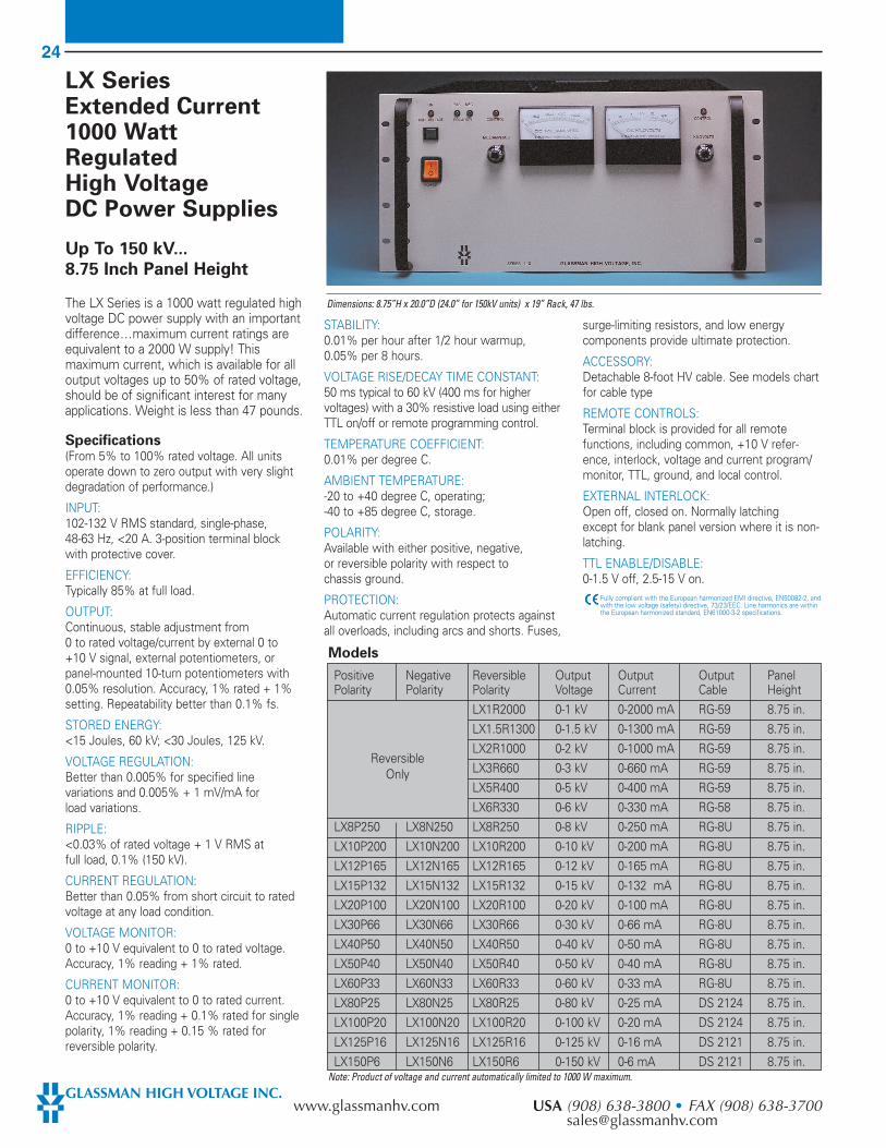
LX SeriesExtended Current1000 WattRegulatedHigh VoltageDC Power Supplies
Up To 150 kV...
8.75 Inch Panel Height
The LX Series is a 1000 watt regulated highvoltage DC power supply with an importantdifference...maximum current ratings areequivalent to a 2000 W supply! Thismaximum current, which is available for alloutput voltages up to 50% of rated voltage,should be of significant interest for manyapplications. Weight is less than 47 pounds.
Specifications (From 5% to 100% rated voltage. All unitsoperate down to zero output with very slightdegradation of performance.)
INPUT: 102-132 V RMS standard, single-phase,48-63 Hz, <20 A. 3-position terminal blockwith protective cover.
EFFICIENCY: Typically 85% at full load.
OUTPUT: Continuous, stable adjustment from0 to rated voltage/current by external 0 to+10 V signal, external potentiometers, orpanel-mounted 10-turn potentiometers with0.05% resolution. Accuracy, 1% rated + 1%setting. Repeatability better than 0.1% fs.
STORED ENERGY: <15 Joules, 60 kV; <30 Joules, 125 kV.
VOLTAGE REGULATION: Better than 0.005% for specified linevariations and 0.005% + 1 mV/mA forload variations.
RIPPLE: <0.03% of rated voltage + 1 V RMS atfull load, 0.1% (150 kV).
CURRENT REGULATION: Better than 0.05% from short circuit to ratedvoltage at any load condition.
VOLTAGE MONITOR: 0 to +10 V equivalent to 0 to rated voltage.Accuracy, 1% reading + 1% rated.
CURRENT MONITOR: 0 to +10 V equivalent to 0 to rated current.Accuracy, 1% reading + 0.1% rated for singlepolarity, 1% reading + 0.15 % rated forreversible polarity.
STABILITY: 0.01% per hour after 1/2 hour warmup,0.05% per 8 hours.
VOLTAGE RISE/DECAY TIME CONSTANT: 50 ms typical to 60 kV (400 ms for highervoltages) with a 30% resistive load using eitherTTL on/off or remote programming control.
TEMPERATURE COEFFICIENT: 0.01% per degree C.
AMBIENT TEMPERATURE: -20 to +40 degree C, operating;-40 to +85 degree C, storage.
POLARITY: Available with either positive, negative,or reversible polarity with respect tochassis ground.
PROTECTION: Automatic current regulation protects againstall overloads, including arcs and shorts. Fuses,
surge-limiting resistors, and low energycomponents provide ultimate protection.
ACCESSORY: Detachable 8-foot HV cable. See models chartfor cable type
REMOTE CONTROLS: Terminal block is provided for all remotefunctions, including common, +10 V refer-ence, interlock, voltage and current program/monitor, TTL, ground, and local control.
EXTERNAL INTERLOCK: Open off, closed on. Normally latching except for blank panel version where it is non-latching.
TTL ENABLE/DISABLE: 0-1.5 V off, 2.5-15 V on.
Fully compliant with the European harmonized EMI directive, EN50082-2, andwith the low voltage (safety) directive, 73/23/EEC. Line harmonics are withinthe European harmonized standard, EN61000-3-2 specifications.
Positive Negative Reversible Output Output Output PanelPolarity Polarity Polarity Voltage Current Cable Height
LX1R2000 0-1 kV 0-2000 mA RG-59 8.75 in.LX1.5R1300 0-1.5 kV 0-1300 mA RG-59 8.75 in.LX2R1000 0-2 kV 0-1000 mA RG-59 8.75 in.LX3R660 0-3 kV 0-660 mA RG-59 8.75 in.LX5R400 0-5 kV 0-400 mA RG-59 8.75 in.LX6R330 0-6 kV 0-330 mA RG-58 8.75 in.
LX8P250 LX8N250 LX8R250 0-8 kV 0-250 mA RG-8U 8.75 in.LX10P200 LX10N200 LX10R200 0-10 kV 0-200 mA RG-8U 8.75 in.LX12P165 LX12N165 LX12R165 0-12 kV 0-165 mA RG-8U 8.75 in.LX15P132 LX15N132 LX15R132 0-15 kV 0-132 mA RG-8U 8.75 in.LX20P100 LX20N100 LX20R100 0-20 kV 0-100 mA RG-8U 8.75 in.LX30P66 LX30N66 LX30R66 0-30 kV 0-66 mA RG-8U 8.75 in.LX40P50 LX40N50 LX40R50 0-40 kV 0-50 mA RG-8U 8.75 in.LX50P40 LX50N40 LX50R40 0-50 kV 0-40 mA RG-8U 8.75 in.LX60P33 LX60N33 LX60R33 0-60 kV 0-33 mA RG-8U 8.75 in.LX80P25 LX80N25 LX80R25 0-80 kV 0-25 mA DS 2124 8.75 in.LX100P20 LX100N20 LX100R20 0-100 kV 0-20 mA DS 2124 8.75 in.LX125P16 LX125N16 LX125R16 0-125 kV 0-16 mA DS 2121 8.75 in.LX150P6 LX150N6 LX150R6 0-150 kV 0-6 mA DS 2121 8.75 in.
Models
ReversibleOnly
Note: Product of voltage and current automatically limited to 1000 W maximum.
Dimensions: 8.75”H x 20.0”D (24.0” for 150kV units) x 19” Rack, 47 lbs.

25
EUROPE (UK) (1256) 883007 • FAX (1256) 883017 JAPAN (045) 902-9988 • FAX (045) [email protected] [email protected]
EQ Series1.2 kW RegulatedHigh VoltageDC Power Supplies
1 to 60 kV, 3.5" Panel
Single-phase 198-264 VInput, 1420 VA
Power Factor Corrected to >0.995.Harmonics Well BelowIEC 555-2 Specs
The EQ Series are sophisticated, 1.2 kW,high voltage power supplies in a small andlightweight package. They are designed tomeet the growing demands from bothusers and electric utilities for switchingpower supplies with excellent input powerfactors that draw harmonic currents belowthose specified in EN61000-3-2
Specifications(From 5% to 100% rated voltage. All unitsoperate down to zero output with very slightdegradation of performance.)
INPUT:198-264 V RMS standard, single-phase,48-63 Hz, 1420 VA maximum. <7 A at 220 V.Connector per IEC 320/VI with mating linecord terminated with NEMA 6-15 plug.
EFFICIENCY:Typically 85% at full load. Power factor >0.995.
OUTPUT:Continuous, stable adjustment from 0 to ratedvoltage/current by external 0 to +10 V signal,external potentiometers, or panel-mounted10-turn potentiometers with 0.05% resolution.Accuracy, 0.25% rated + 0.25% setting.Repeatability better than 0.1% of setting.
STATIC VOLTAGE REGULATION:Better than 0.005% for specified line variationsand 0.005% + 0.5 mV/mA for load variations.
DYNAMIC VOLTAGE REGULATION:For load transients from 10% to 100% and100% to 10%, typical deviation is 2% ofoutput voltage with recovery to within 1% in500 µs and to 0.1% in 1 ms.
RIPPLE:<0.02% of rated voltage + 300 mV RMS atfull load.
CURRENT REGULATION:Better than 0.05% + 100 µA from short circuitto rated voltage at any load condition.
VOLTAGE MONITOR:0 to +10 V equivalent to 0 to rated voltage.Accuracy, 0.25% reading + 0.25% rated.
CURRENT MONITOR:0 to +10 V equivalent to 0 to rated current.Accuracy, 1% reading + 0.05% rated forsingle polarity, 1% reading + 0.1% rated forreversible polarity
STABILITY:0.01% per hour after 1/2 hour warmup,0.05% per 8 hours.
VOLTAGE RISE/DECAY TIME CONSTANT:50 ms typical with a 10% resistive load usingeither TTL on/off or remote programmingcontrol.
TEMPERATURE COEFFICIENT:0.01% per degree C.
AMBIENT TEMPERATURE:-20 to +40 degree C, operating;-40 to +85 degree C, storage.
POLARITY:Available with either positive, negative, or reversible polarity with respect tochassis ground.
PROTECTION:Automatic current regulation protects againstall overloads, including arcs and shorts. Fuses,surge-limiting resistors, and low energycomponents provide ultimate protection,.
ARC COUNT: Internal circuitry senses the number of arcscaused by flawed external load characteristics.If the rate of consecutive arcs exceeds approxi-mately 2 per second, the supply will turn offfor approximately 2 seconds to allow clearanceof the fault and then automatically resumenormal operation. Custom modifications of thisfeature are available. Consult the factory.
REMOTE CONTROLS:Terminal block is provided for all remotefunctions, including common, +10 V reference,interlock, voltage and current program/monitor,HV enable, ground, and local control.
EXTERNAL INTERLOCK:Open off, closed on. Normally latching exceptfor blank panel version where it is non-latching.
REMOTE HV ENABLE:0-1.5 V off, 2.5-15 V on.
Fully compliant with the European harmonized EMI directive, EN50082-2,and with the low voltage (safety) directive, 73/23/EEC. Line harmonics arewithin the European harmonized standard, EN61000-3-2 specifications.
Positive Negative Reversible Output Output Stored OutputPolarity Polarity Polarity Voltage Current Energy (J) Cable
EQ1R1200 0-1kV 0-1200mA 1.0 RG-58
EQ1.5R800 0-1.5kV 0-800mA 1.1 RG-58
EQ2R600 0-2kV 0-600mA 1.0 RG-58
EQ3R400 0-3kV 0-400mA 1.1 RG-58
EQ5R240 0-5kV 0-240mA 1.2 RG-58
EQ6R200 0-6kV 0-200mA 1.4 RG-58
EQ8P150 EQ8N150 EQ8R150 0-8kV 0-150mA 1.3 RG-8U
EQ10P120 EQ10N120 EQ10R120 0-10kV 0-120mA 1.6 RG-8U
EQ12P100 EQ12N100 EQ12R100 0-12kV 0-100mA 2.0 RG-8U
EQ15P80 EQ15N80 EQ15R80 0-15kV 0-80mA 1.6 RG-8U
EQ20P60 EQ20N60 EQ20R60 0-20kV 0-60mA 2.0 RG-8U
EQ30P40 EQ30N40 EQ30R40 0-30kV 0-40mA 2.1 RG-8U
EQ40P30 EQ40N30 EQ40R30 0-40kV 0-30mA 2.8 RG-8U
EQ50P24 EQ50N24 EQ50R24 0-50kV 0-24mA 3.4 RG-8U
EQ60P20 EQ60N20 EQ60R20 0-60kV 0-20mA 4.1 RG-8U
Models
ReversibleOnly
Dimensions: 3.5”H x 20.5”D x 19” Rack, 22 lbs.
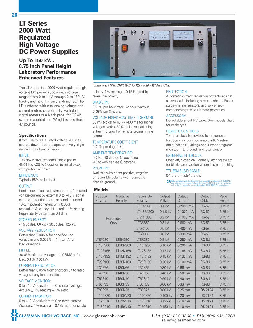
26
GLASSMAN HIGH VOLTAGE INC. www.glassmanhv.com USA (908) 638-3800 • FAX (908) [email protected]
LT Series2000 WattRegulatedHigh VoltageDC Power Supplies
Up To 150 kV...
8.75 Inch Panel Height
Laboratory Performance
Enhanced Features
The LT Series is a 2000 watt regulated highvoltage DC power supply with voltageranges from 0 to 1 kV through 0 to 150 kV.Rack-panel height is only 8.75 inches. TheLT is offered with dual analog voltage andcurrent meters or, optionally, with dualdigital meters or a blank panel for OEM/systems applications. Weight is less than47 pounds.
Specifications (From 5% to 100% rated voltage. All unitsoperate down to zero output with very slightdegradation of performance.)
INPUT: 198-264 V RMS standard, single-phase,48-63 Hz, <20 A. 3-position terminal blockwith protective cover.
EFFICIENCY: Typically 85% at full load.
OUTPUT: Continuous, stable adjustment from 0 to ratedvoltage/current by external 0 to +10 V signal,external potentiometers, or panel-mounted10-turn potentiometers with 0.05%resolution. Accuracy, 1% rated + 1% setting.Repeatability better than 0.1% fs.
STORED ENERGY: <15 Joules, 60 kV; <30 Joules, 125 kV.
VOLTAGE REGULATION: Better than 0.005% for specified linevariations and 0.005% + 1 mV/mA forload variations.
RIPPLE: <0.03% of rated voltage + 1 V RMS at fullload, 0.1% (150 kV).
CURRENT REGULATION:Better than 0.05% from short circuit to ratedvoltage at any load condition.
VOLTAGE MONITOR: 0 to +10 V equivalent to 0 to rated voltage.Accuracy, 1% reading + 1% rated.
CURRENT MONITOR: 0 to +10 V equivalent to 0 to rated current.Accuracy, 1% reading + 0.1% rated for single
polarity, 1% reading + 0.15% rated forreversible polarity.
STABILITY: 0.01% per hour after 1/2 hour warmup,0.05% per 8 hours.
VOLTAGE RISE/DECAY TIME CONSTANT: 50 ms typical to 60 kV (400 ms for highervoltages) with a 30% resistive load usingeither TTL on/off or remote programmingcontrol.
TEMPERATURE COEFFICIENT:0.01% per degree C.
AMBIENT TEMPERATURE:-20 to +40 degree C, operating;-40 to +85 degree C, storage.
POLARITY: Available with either positive, negative,or reversible polarity with respect tochassis ground.
PROTECTION: Automatic current regulation protects againstall overloads, including arcs and shorts. Fuses,surge-limiting resistors, and low energycomponents provide ultimate protection.
ACCESSORY: Detachable 8-foot HV cable. See models chartfor cable type
REMOTE CONTROLS: Terminal block is provided for all remotefunctions, including common, +10 V refer-ence, interlock, voltage and current program/monitor, TTL, ground, and local control.
EXTERNAL INTERLOCK: Open off, closed on. Normally latching exceptfor blank panel version where it is non-latching.
TTL ENABLE/DISABLE: 0-1.5 V off, 2.5-15 V on.
Fully compliant with the European harmonized EMI directive, EN50082-2,and with the low voltage (safety) directive, 73/23/EEC. Line harmonics arewithin the European harmonized standard, EN61000-3-2 specifications.
Positive Negative Reversible Output Output Output PanelPolarity Polarity Polarity Voltage Current Cable Height
LT1R2000 0-1 kV 0-2000 mA RG-59 8.75 in.LT1.5R1300 0-1.5 kV 0-1300 mA RG-59 8.75 in.LT2R1000 0-2 kV 0-1000 mA RG-59 8.75 in.LT3R660 0-3 kV 0-660 mA RG-59 8.75 in.LT5R400 0-5 kV 0-400 mA RG-59 8.75 in.LT6R330 0-6 kV 0-330 mA RG-58 8.75 in.
LT8P250 LT8N250 LT8R250 0-8 kV 0-250 mA RG-8U 8.75 in.LT10P200 LT10N200 LT10R200 0-10 kV 0-200 mA RG-8U 8.75 in.LT12P165 LT12N165 LT12R165 0-12 kV 0-165 mA RG-8U 8.75 in.LT15P132 LT15N132 LT15R132 0-15 kV 0-132 mA RG-8U 8.75 in.LT20P100 LT20N100 LT20R100 0-20 kV 0-100 mA RG-8U 8.75 in.LT30P66 LT30N66 LT30R66 0-30 kV 0-66 mA RG-8U 8.75 in.LT40P50 LT40N50 LT40R50 0-40 kV 0-50 mA RG-8U 8.75 in.LT50P40 LT50N40 LT50R40 0-50 kV 0-40 mA RG-8U 8.75 in.LT60P33 LT60N33 LT60R33 0-60 kV 0-33 mA RG-8U 8.75 in.LT80P25 LT80N25 LT80R25 0-80 kV 0-25 mA DS 2124 8.75 in.LT100P20 LT100N20 LT100R20 0-100 kV 0-20 mA DS 2124 8.75 in.LT125P16 LT125N16 LT125R16 0-125 kV 0-16 mA DS 2121 8.75 in.LT150P10 LT150N10 LT150R10 0-150 kV 0-10 mA DS 2121 8.75 in.
Models
ReversibleOnly
Dimensions: 8.75”H x 20.0”D (24.0” for 150kV units) x 19” Rack, 47 lbs.
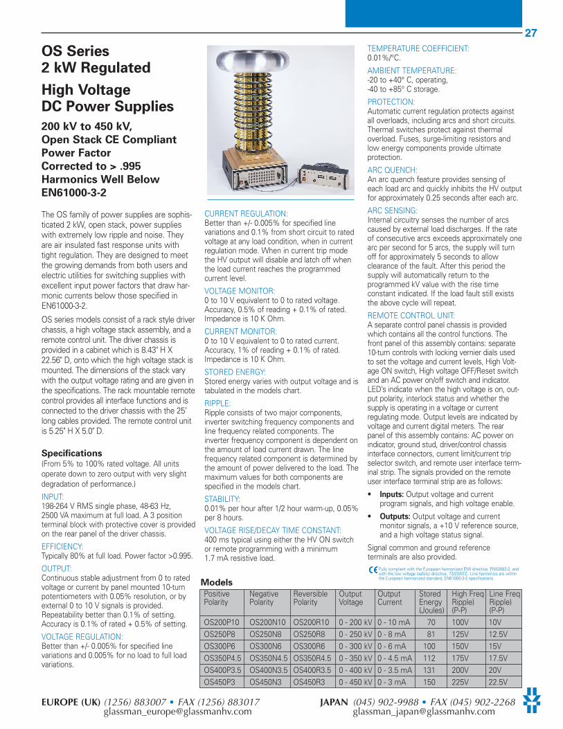
27
EUROPE (UK) (1256) 883007 • FAX (1256) 883017 JAPAN (045) 902-9988 • FAX (045) [email protected] [email protected]
OS Series2 kW Regulated
High VoltageDC Power Supplies
200 kV to 450 kV,
Open Stack CE Compliant
Power Factor
Corrected to > .995
Harmonics Well Below
EN61000-3-2
The OS family of power supplies are sophis-ticated 2 kW, open stack, power supplieswith extremely low ripple and noise. Theyare air insulated fast response units withtight regulation. They are designed to meetthe growing demands from both users andelectric utilities for switching supplies withexcellent input power factors that draw har-monic currents below those specified inEN61000-3-2.
OS series models consist of a rack style driverchassis, a high voltage stack assembly, and aremote control unit. The driver chassis isprovided in a cabinet which is 8.43" H X22.56" D, onto which the high voltage stack ismounted. The dimensions of the stack varywith the output voltage rating and are given inthe specifications. The rack mountable remotecontrol provides all interface functions and isconnected to the driver chassis with the 25’long cables provided. The remote control unitis 5.25" H X 5.0" D.
Specifications (From 5% to 100% rated voltage. All unitsoperate down to zero output with very slightdegradation of performance.)
INPUT: 198-264 V RMS single phase, 48-63 Hz,2500 VA maximum at full load. A 3 positionterminal block with protective cover is providedon the rear panel of the driver chassis.
EFFICIENCY: Typically 80% at full load. Power factor >0.995.
OUTPUT: Continuous stable adjustment from 0 to ratedvoltage or current by panel mounted 10-turnpotentiometers with 0.05% resolution, or byexternal 0 to 10 V signals is provided.Repeatability better than 0.1% of setting.Accuracy is 0.1% of rated + 0.5% of setting.
VOLTAGE REGULATION: Better than +/- 0.005% for specified linevariations and 0.005% for no load to full loadvariations.
CURRENT REGULATION: Better than +/- 0.005% for specified linevariations and 0.1% from short circuit to ratedvoltage at any load condition, when in currentregulation mode. When in current trip modethe HV output will disable and latch off whenthe load current reaches the programmedcurrent level.
VOLTAGE MONITOR: 0 to 10 V equivalent to 0 to rated voltage.Accuracy, 0.5% of reading + 0.1% of rated.Impedance is 10 K Ohm.
CURRENT MONITOR: 0 to 10 V equivalent to 0 to rated current.Accuracy, 1% of reading + 0.1% of rated.Impedance is 10 K Ohm.
STORED ENERGY: Stored energy varies with output voltage and istabulated in the models chart.
RIPPLE: Ripple consists of two major components,inverter switching frequency components andline frequency related components. Theinverter frequency component is dependent onthe amount of load current drawn. The linefrequency related component is determined bythe amount of power delivered to the load. Themaximum values for both components arespecified in the models chart.
STABILITY: 0.01% per hour after 1/2 hour warm-up, 0.05%per 8 hours.
VOLTAGE RISE/DECAY TIME CONSTANT: 400 ms typical using either the HV ON switchor remote programming with a minimum1.7 mA resistive load.
TEMPERATURE COEFFICIENT: 0.01%/°C.
AMBIENT TEMPERATURE: -20 to +40° C, operating, -40 to +85° C storage.
PROTECTION: Automatic current regulation protects againstall overloads, including arcs and short circuits.Thermal switches protect against thermaloverload. Fuses, surge-limiting resistors andlow energy components provide ultimateprotection.
ARC QUENCH: An arc quench feature provides sensing ofeach load arc and quickly inhibits the HV outputfor approximately 0.25 seconds after each arc.
ARC SENSING: Internal circuitry senses the number of arcscaused by external load discharges. If the rateof consecutive arcs exceeds approximately onearc per second for 5 arcs, the supply will turnoff for approximately 5 seconds to allowclearance of the fault. After this period thesupply will automatically return to theprogrammed kV value with the rise timeconstant indicated. If the load fault still existsthe above cycle will repeat.
REMOTE CONTROL UNIT: A separate control panel chassis is providedwhich contains all the control functions. Thefront panel of this assembly contains: separate10-turn controls with locking vernier dials usedto set the voltage and current levels, High Volt-age ON switch, High voltage OFF/Reset switchand an AC power on/off switch and indicator.LED’s indicate when the high voltage is on, out-put polarity, interlock status and whether thesupply is operating in a voltage or currentregulating mode. Output levels are indicated byvoltage and current digital meters. The rearpanel of this assembly contains: AC power onindicator, ground stud, driver/control chassisinterface connectors, current limit/current tripselector switch, and remote user interface term-inal strip. The signals provided on the remoteuser interface terminal strip are as follows:
• Inputs: Output voltage and currentprogram signals, and high voltage enable.
• Outputs: Output voltage and currentmonitor signals, a +10 V reference source,and a high voltage status signal.
Signal common and ground referenceterminals are also provided.
Fully compliant with the European harmonized EMI directive, EN50082-2, andwith the low voltage (safety) directive, 73/23/EEC. Line harmonics are withinthe European harmonized standard, EN61000-3-2 specifications.
Models
Positive Negative Reversible Output Output Stored High Freq Line FreqPolarity Polarity Polarity Voltage Current Energy Ripple) Ripple)
(Joules) (P-P) (P-P)OS200P10 OS200N10 OS200R10 0 - 200 kV 0 - 10 mA 70 100V 10VOS250P8 OS250N8 OS250R8 0 - 250 kV 0 - 8 mA 81 125V 12.5VOS300P6 OS300N6 OS300R6 0 - 300 kV 0 - 6 mA 100 150V 15VOS350P4.5 OS350N4.5 OS350R4.5 0 - 350 kV 0 - 4.5 mA 112 175V 17.5VOS400P3.5 OS400N3.5 OS400R3.5 0 - 400 kV 0 - 3.5 mA 131 200V 20VOS450P3 OS450N3 OS450R3 0 - 450 kV 0 - 3 mA 150 225V 22.5V
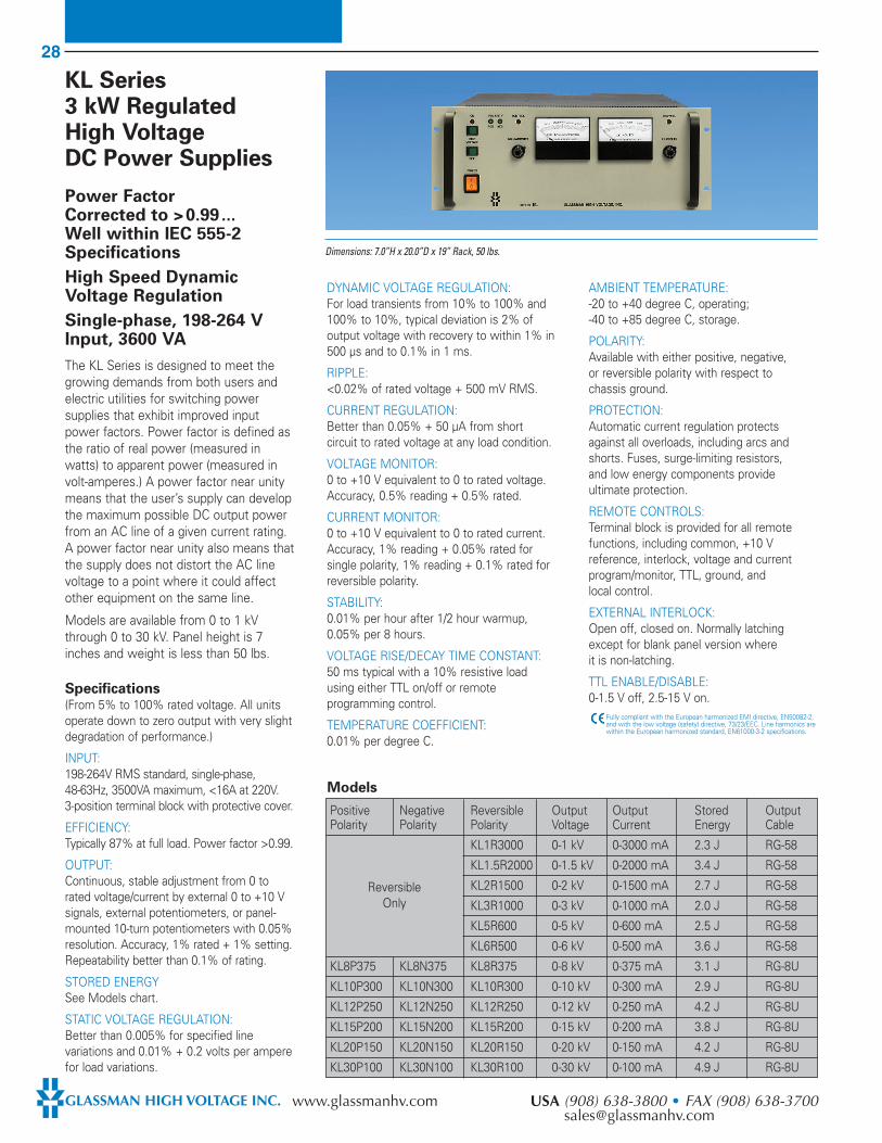
28
GLASSMAN HIGH VOLTAGE INC. www.glassmanhv.com USA (908) 638-3800 • FAX (908) [email protected]
KL Series3 kW RegulatedHigh VoltageDC Power Supplies
Power FactorCorrected to >0.99...Well within IEC 555-2Specifications
High Speed DynamicVoltage Regulation
Single-phase, 198-264 VInput, 3600 VA
The KL Series is designed to meet thegrowing demands from both users andelectric utilities for switching powersupplies that exhibit improved inputpower factors. Power factor is defined asthe ratio of real power (measured inwatts) to apparent power (measured involt-amperes.) A power factor near unitymeans that the user’s supply can developthe maximum possible DC output powerfrom an AC line of a given current rating.A power factor near unity also means thatthe supply does not distort the AC linevoltage to a point where it could affectother equipment on the same line.
Models are available from 0 to 1 kVthrough 0 to 30 kV. Panel height is 7inches and weight is less than 50 lbs.
Specifications(From 5% to 100% rated voltage. All unitsoperate down to zero output with very slightdegradation of performance.)
INPUT:198-264V RMS standard, single-phase,48-63Hz, 3500VA maximum, <16A at 220V.3-position terminal block with protective cover.
EFFICIENCY:Typically 87% at full load. Power factor >0.99.
OUTPUT:Continuous, stable adjustment from 0 torated voltage/current by external 0 to +10 Vsignals, external potentiometers, or panel-mounted 10-turn potentiometers with 0.05%resolution. Accuracy, 1% rated + 1% setting.Repeatability better than 0.1% of rating.
STORED ENERGYSee Models chart.
STATIC VOLTAGE REGULATION:Better than 0.005% for specified linevariations and 0.01% + 0.2 volts per amperefor load variations.
DYNAMIC VOLTAGE REGULATION:For load transients from 10% to 100% and100% to 10%, typical deviation is 2% ofoutput voltage with recovery to within 1% in500 µs and to 0.1% in 1 ms.
RIPPLE:<0.02% of rated voltage + 500 mV RMS.
CURRENT REGULATION:Better than 0.05% + 50 µA from shortcircuit to rated voltage at any load condition.
VOLTAGE MONITOR:0 to +10 V equivalent to 0 to rated voltage.Accuracy, 0.5% reading + 0.5% rated.
CURRENT MONITOR:0 to +10 V equivalent to 0 to rated current.Accuracy, 1% reading + 0.05% rated forsingle polarity, 1% reading + 0.1% rated forreversible polarity.
STABILITY:0.01% per hour after 1/2 hour warmup,0.05% per 8 hours.
VOLTAGE RISE/DECAY TIME CONSTANT:50 ms typical with a 10% resistive loadusing either TTL on/off or remoteprogramming control.
TEMPERATURE COEFFICIENT:0.01% per degree C.
AMBIENT TEMPERATURE:-20 to +40 degree C, operating;-40 to +85 degree C, storage.
POLARITY:Available with either positive, negative,or reversible polarity with respect tochassis ground.
PROTECTION:Automatic current regulation protectsagainst all overloads, including arcs andshorts. Fuses, surge-limiting resistors,and low energy components provideultimate protection.
REMOTE CONTROLS:Terminal block is provided for all remotefunctions, including common, +10 Vreference, interlock, voltage and currentprogram/monitor, TTL, ground, andlocal control.
EXTERNAL INTERLOCK:Open off, closed on. Normally latchingexcept for blank panel version whereit is non-latching.
TTL ENABLE/DISABLE:0-1.5 V off, 2.5-15 V on.
Fully compliant with the European harmonized EMI directive, EN50082-2,and with the low voltage (safety) directive, 73/23/EEC. Line harmonics arewithin the European harmonized standard, EN61000-3-2 specifications.
Positive Negative Reversible Output Output Stored OutputPolarity Polarity Polarity Voltage Current Energy Cable
KL1R3000 0-1 kV 0-3000 mA 2.3 J RG-58
KL1.5R2000 0-1.5 kV 0-2000 mA 3.4 J RG-58
KL2R1500 0-2 kV 0-1500 mA 2.7 J RG-58
KL3R1000 0-3 kV 0-1000 mA 2.0 J RG-58
KL5R600 0-5 kV 0-600 mA 2.5 J RG-58
KL6R500 0-6 kV 0-500 mA 3.6 J RG-58
KL8P375 KL8N375 KL8R375 0-8 kV 0-375 mA 3.1 J RG-8U
KL10P300 KL10N300 KL10R300 0-10 kV 0-300 mA 2.9 J RG-8U
KL12P250 KL12N250 KL12R250 0-12 kV 0-250 mA 4.2 J RG-8U
KL15P200 KL15N200 KL15R200 0-15 kV 0-200 mA 3.8 J RG-8U
KL20P150 KL20N150 KL20R150 0-20 kV 0-150 mA 4.2 J RG-8U
KL30P100 KL30N100 KL30R100 0-30 kV 0-100 mA 4.9 J RG-8U
Models
ReversibleOnly
Dimensions: 7.0”H x 20.0”D x 19” Rack, 50 lbs.
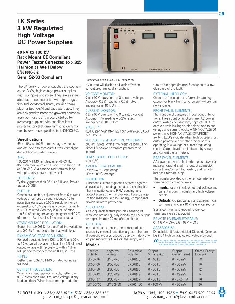
29
EUROPE (UK) (1256) 883007 • FAX (1256) 883017 JAPAN (045) 902-9988 • FAX (045) [email protected] [email protected]
LK Series 3 kW Regulated High VoltageDC Power Supplies
40 kV to 100 kV Rack Mount CE CompliantPower Factor Corrected to >.995Harmonics Well BelowEN61000-3-2
Semi S2-93 Compliant
The LK family of power supplies are sophisti-cated, 3 kW, high voltage power supplieswith low ripple and noise. They are air insul-ated, fast response units, with tight regula-tion and low-stored energy making themideal for both OEM and Laboratory use. Theyare designed to meet the growing demandsfrom both users and electric utilities forswitching supplies with excellent inputpower factors that draw harmonic currentswell below those specified in EN61000-3-2.
Specifications(From 5% to 100% rated voltage. All unitsoperate down to zero output with very slightdegradation of performance.)
INPUT: 198-264 V RMS, single-phase, 48-63 Hz,3500 VA maximum at full load. Less than 16 Aat 220 VAC. A 3-position rear terminal blockwith protective cover is provided.
EFFICIENCY: Typically greater than 85% at full load. Powerfactor >0.995.
OUTPUT: Continuous, stable, adjustment from 0 to ratedvoltage or current by panel mounted 10-turnpotentiometers with 0.05% resolution, or byexternal 0 to 10 V signals is provided. Linearityis < 1% of rated. Accuracy is 0.2% of rated+ 0.5% of setting for voltage program and 0.2%of rated + 1% of setting for current program.
STATIC VOLTAGE REGULATION: Better than ±0.005% for specified line variationsand 0.01% for no load to full load variations.
DYNAMIC VOLTAGE REGULATION: For load transients from 10% to 99% and 99%to 10%, typical deviation is less than 2% of ratedoutput voltage with recovery to within 1% in500 µs and recovery to within 0.1% in 1 ms.
RIPPLE: Better than 0.025% RMS of rated voltage atfull load.
CURRENT REGULATION: When in current regulation mode, better than0.1% from short circuit to rated voltage at anyload condition. When in current trip mode the
HV output will disable and latch off whencurrent program level is reached.
VOLTAGE MONITOR: 0 to +10 V equivalent to 0 to rated voltage.Accuracy, 0.5% reading + 0.2% rated.Impedance is 10 K Ohm.
CURRENT MONITOR: 0 to +10 V equivalent to 0 to rated current.Accuracy, 1% reading + 0.2% rated.Impedance is 10 K Ohm.
STABILITY: 0.01% per hour after 1/2 hour warm-up, 0.05%per 8 hours.
VOLTAGE RISE/DECAY TIME CONSTANT: 200 ms typical with a 7% resistive load usingeither HV enable or remote programmingcontrol.
TEMPERATURE COEFFICIENT: 0.01%/ºC.
AMBIENT TEMPERATURE: -20 to +40ºC, operating; -40 to +85ºC, storage.
PROTECTION: Automatic current regulation protects againstall overloads, including arcs and short circuits.Thermal switches and RPM sensing fansprotect against thermal overload. Fuses, surge-limiting resistors, and low energy componentsprovide ultimate protection.
ARC QUENCH: An arc quench feature provides sensing ofeach load arc and quickly inhibits the HV outputfor approximately 20 ms after each arc.
ARC COUNT: Internal circuitry senses the number of arcscaused by external load discharges. If the rateof consecutive arcs exceeds approximately onearc per second for five arcs, the supply will
turn off for approximately 5 seconds to allowclearance of the fault.
EXTERNAL INTERLOCK: Open = off, closed = on. Normally latchingexcept for blank front panel version where it isnon-latching.
FRONT PANEL ELEMENTS: The front panel contains all local control func-tions. These control functions are: AC poweron/off switch and pilot light, separate 10-turncontrols with locking vernier dials used to setvoltage and current levels, HIGH VOLTAGE ONswitch, and HIGH VOLTAGE OFF/RESETswitch. LED's indicate when high voltage is on,output polarity, and whether the supply isoperating in a voltage or current regulatingmode. Output levels are indicated by voltageand current digital meters.
REAR PANEL ELEMENTS:AC power entry terminal strip, fuses, power onindicator, ground stud, HV output connector,current limit/current trip switch, and remoteinterface terminal strip.
The signals provided on the remote interfaceterminal strip are as follows:
• Inputs: Safety interlock, output voltage andcurrent program signals, and high voltageenable.
• Outputs: Output voltage and current moni-tor signals, and a +10 V reference source.
Signal common and ground referenceterminals are also provided.
REMOTE HV ENABLE/DISABLE: 0 - 1.5 V = OFF, 2.5 - 15 V = ON.
ACCESSORIES: Detachable, 8 foot, shielded Dielectric SciencesDS2124 high voltage coaxial cable provided.
Fully compliant with the European harmonized EMI directive, EN50082-2, andwith the low voltage (safety) directive, 73/23/EEC. Line harmonics are withinthe European harmonized standard, EN61000-3-2 specifications.Models
Positive Negative Reversible Output Output Stored EnergyPolarity Polarity Polarity Voltage (kV) Current (mA) (Joules)LK40P75 LK40N75 LK40R75 0 - 40 kV 0 - 75 mA 8LK50P60 LK50N60 LK50R60 0 - 50 kV 0 - 60 mA 10LK60P50 LK60N50 LK60R50 0 - 60 kV 0 - 50 mA 12LK70P43 LK70N43 LK70R43 0 - 70 kV 0 - 43 mA 14LK80P37 LK80N37 LK80R37 0 - 80 kV 0 - 37.5 mA 16LK100P30 LK100N30 LK100R30 0 - 100 kV 0 - 30 mA 20
Dimensions: 8.75”H x 24.0”D x 19” Rack, 55 lbs.
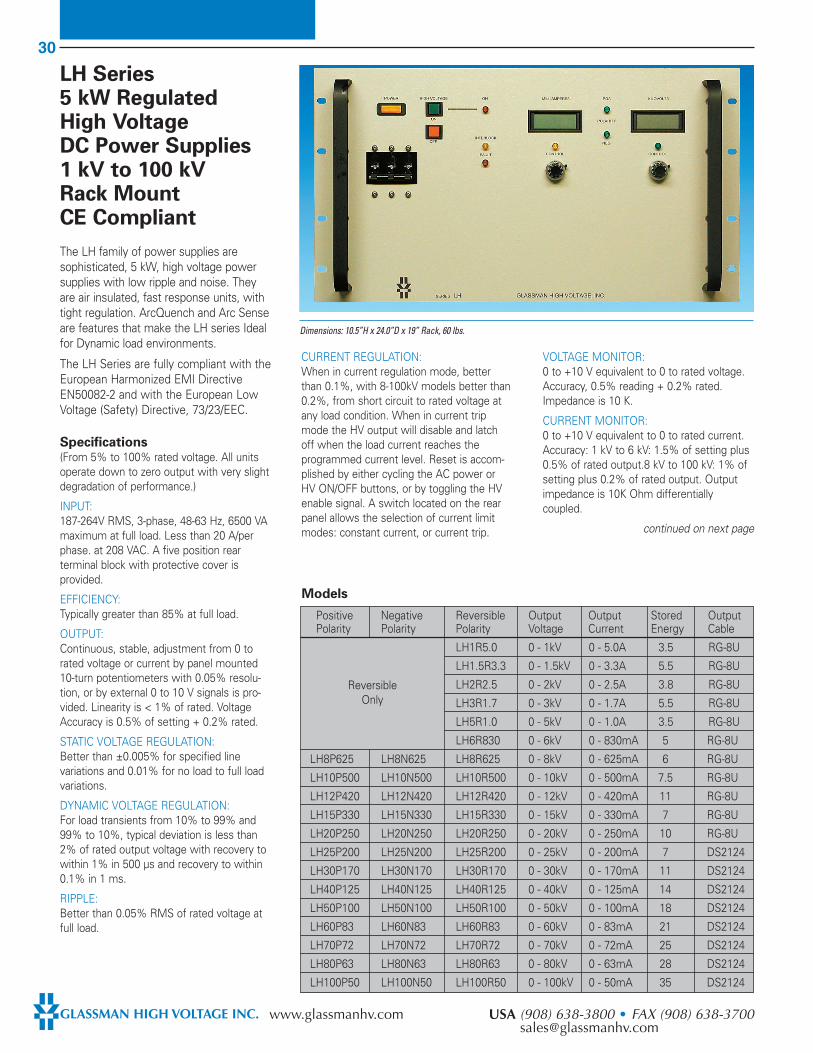
30
GLASSMAN HIGH VOLTAGE INC. www.glassmanhv.com USA (908) 638-3800 • FAX (908) [email protected]
LH Series5 kW RegulatedHigh VoltageDC Power Supplies1 kV to 100 kVRack MountCE Compliant
The LH family of power supplies aresophisticated, 5 kW, high voltage powersupplies with low ripple and noise. Theyare air insulated, fast response units, withtight regulation. ArcQuench and Arc Senseare features that make the LH series Idealfor Dynamic load environments.
The LH Series are fully compliant with theEuropean Harmonized EMI DirectiveEN50082-2 and with the European LowVoltage (Safety) Directive, 73/23/EEC.
Specifications(From 5% to 100% rated voltage. All unitsoperate down to zero output with very slightdegradation of performance.)
INPUT: 187-264V RMS, 3-phase, 48-63 Hz, 6500 VAmaximum at full load. Less than 20 A/perphase. at 208 VAC. A five position rearterminal block with protective cover isprovided.
EFFICIENCY: Typically greater than 85% at full load.
OUTPUT: Continuous, stable, adjustment from 0 torated voltage or current by panel mounted10-turn potentiometers with 0.05% resolu-tion, or by external 0 to 10 V signals is pro-vided. Linearity is < 1% of rated. VoltageAccuracy is 0.5% of setting + 0.2% rated.
STATIC VOLTAGE REGULATION: Better than ±0.005% for specified linevariations and 0.01% for no load to full loadvariations.
DYNAMIC VOLTAGE REGULATION: For load transients from 10% to 99% and99% to 10%, typical deviation is less than2% of rated output voltage with recovery towithin 1% in 500 µs and recovery to within0.1% in 1 ms.
RIPPLE: Better than 0.05% RMS of rated voltage atfull load.
CURRENT REGULATION: When in current regulation mode, betterthan 0.1%, with 8-100kV models better than0.2%, from short circuit to rated voltage atany load condition. When in current tripmode the HV output will disable and latchoff when the load current reaches theprogrammed current level. Reset is accom-plished by either cycling the AC power orHV ON/OFF buttons, or by toggling the HVenable signal. A switch located on the rearpanel allows the selection of current limitmodes: constant current, or current trip.
VOLTAGE MONITOR: 0 to +10 V equivalent to 0 to rated voltage.Accuracy, 0.5% reading + 0.2% rated.Impedance is 10 K.
CURRENT MONITOR: 0 to +10 V equivalent to 0 to rated current.Accuracy: 1 kV to 6 kV: 1.5% of setting plus0.5% of rated output.8 kV to 100 kV: 1% ofsetting plus 0.2% of rated output. Outputimpedance is 10K Ohm differentiallycoupled.
continued on next page
Dimensions: 10.5”H x 24.0”D x 19” Rack, 60 lbs.
Models
Positive Negative Reversible Output Output Stored OutputPolarity Polarity Polarity Voltage Current Energy Cable
LH1R5.0 0 - 1kV 0 - 5.0A 3.5 RG-8U
LH1.5R3.3 0 - 1.5kV 0 - 3.3A 5.5 RG-8U
LH2R2.5 0 - 2kV 0 - 2.5A 3.8 RG-8U
LH3R1.7 0 - 3kV 0 - 1.7A 5.5 RG-8U
LH5R1.0 0 - 5kV 0 - 1.0A 3.5 RG-8U
LH6R830 0 - 6kV 0 - 830mA 5 RG-8U
LH8P625 LH8N625 LH8R625 0 - 8kV 0 - 625mA 6 RG-8U
LH10P500 LH10N500 LH10R500 0 - 10kV 0 - 500mA 7.5 RG-8U
LH12P420 LH12N420 LH12R420 0 - 12kV 0 - 420mA 11 RG-8U
LH15P330 LH15N330 LH15R330 0 - 15kV 0 - 330mA 7 RG-8U
LH20P250 LH20N250 LH20R250 0 - 20kV 0 - 250mA 10 RG-8U
LH25P200 LH25N200 LH25R200 0 - 25kV 0 - 200mA 7 DS2124
LH30P170 LH30N170 LH30R170 0 - 30kV 0 - 170mA 11 DS2124
LH40P125 LH40N125 LH40R125 0 - 40kV 0 - 125mA 14 DS2124
LH50P100 LH50N100 LH50R100 0 - 50kV 0 - 100mA 18 DS2124
LH60P83 LH60N83 LH60R83 0 - 60kV 0 - 83mA 21 DS2124
LH70P72 LH70N72 LH70R72 0 - 70kV 0 - 72mA 25 DS2124
LH80P63 LH80N63 LH80R63 0 - 80kV 0 - 63mA 28 DS2124
LH100P50 LH100N50 LH100R50 0 - 100kV 0 - 50mA 35 DS2124
ReversibleOnly
31
EUROPE (UK) (1256) 883007 • FAX (1256) 883017 JAPAN (045) 902-9988 • FAX (045) [email protected] [email protected]
VOLTAGE RISE/DECAY TIME CONSTANT:(Typical using either HV enable or remoteprogramming control and a resistive load.)1-6 kV: t = 50 ms with TBD% min. load.8-20 kV: t = 50 ms with 9% min. load.25-100 kV: t = 200 ms with 7% min load.
TEMPERATURE COEFFICIENT: 0.01%/ºC.
AMBIENT TEMPERATURE: -20 to +40ºC,operating;-40 to +85ºC, storage.
PROTECTION: Automatic current regulation protectsagainst all overloads, including arcs andshort circuits. Thermal switches and RPMsensing fans protect against thermaloverload. Fuses, surge-limiting resistors, andlow energy components provide ultimateprotection.
ARC QUENCH: Optional on models 1 kV through 6 kV;standard on models 8 kV through 100 kV. Anarc quench feature provides sensing of eachload arc and quickly inhibits the HV outputfor approximately 20 ms after each arc.
ARC COUNT: Optional on models 1 kV through 6 kV;standard on models 8 kV through 100 kV.Internal circuitry senses the number of arcscaused by external load discharges. If therate of consecutive arcs exceeds approxi-mately one arc per second for five arcs, thesupply will turn off for approximately fiveseconds to allow clearance of the fault. Afterthis period, the supply will return automati-cally to the programmed output voltagevalue with the voltage rise time constantindicated. If the load fault still exists, theabove cycle will be repeated
EXTERNAL INTERLOCK: Open = off, closed = on. Normally latchingexcept for blank front panel version where itis non-latching.
FRONT PANEL ELEMENTS: The front panel contains all local controlfunctions. These control functions are: ACpower on/off circuit breaker and indicatorlight, separate 10-turn controls with lockingvernier dials used to set voltage and currentlevels, HIGH VOLTAGE ON switch, andHIGH VOLTAGE OFF/RESET switch. LED'sindicate: when high voltage is on, outputpolarity, interlock, fault status, and whetherthe supply is operating in a voltage orcurrent regulating mode. Output levels areindicated by voltage and current digitalmeters.
REAR PANEL ELEMENTS:AC power entry terminal strip, power onindicator, ground stud, HV output connectorcurrent limit/current trip switch, remoteinterface terminal strip and connector.
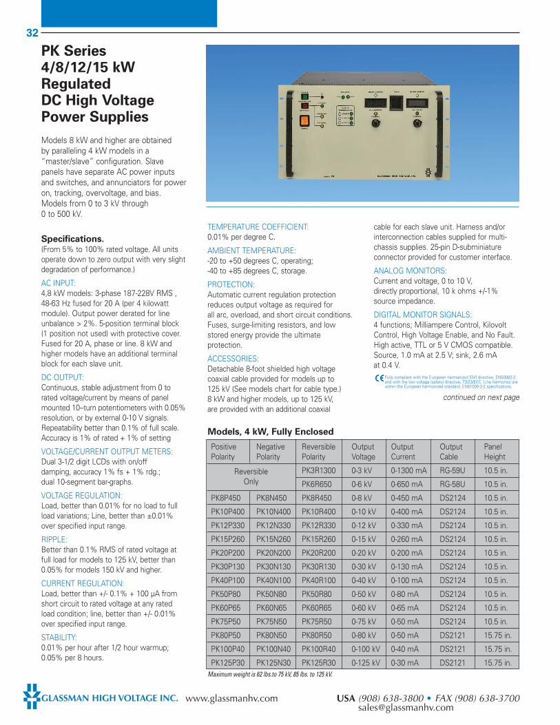
32
GLASSMAN HIGH VOLTAGE INC. www.glassmanhv.com USA (908) 638-3800 • FAX (908) [email protected]
PK Series4/8/12/15 kWRegulatedDC High VoltagePower Supplies
Models 8 kW and higher are obtainedby paralleling 4 kW models in a“master/slave” configuration. Slavepanels have separate AC power inputsand switches, and annunciators for poweron, tracking, overvoltage, and bias.Models from 0 to 3 kV through0 to 500 kV.
Specifications.(From 5% to 100% rated voltage. All unitsoperate down to zero output with very slightdegradation of performance.)
AC INPUT: 4,8 kW models: 3-phase 187-228V RMS ,48-63 Hz fused for 20 A (per 4 kilowattmodule). Output power derated for lineunbalance > 2%. 5-position terminal block(1 position not used) with protective cover.Fused for 20 A, phase or line. 8 kW andhigher models have an additional terminalblock for each slave unit.
DC OUTPUT:Continuous, stable adjustment from 0 torated voltage/current by means of panelmounted 10--turn potentiometers with 0.05%resolution, or by external 0-10 V signals.Repeatability better than 0.1% of full scale.Accuracy is 1% of rated + 1% of setting
VOLTAGE/CURRENT OUTPUT METERS: Dual 3-1/2 digit LCDs with on/off damping, accuracy 1% fs + 1% rdg.; dual 10-segment bar-graphs.
VOLTAGE REGULATION: Load, better than 0.01% for no load to fullload variations; Line, better than ±0.01%over specified input range.
RIPPLE:Better than 0.1% RMS of rated voltage atfull load for models to 125 kV, better than0.05% for models 150 kV and higher.
CURRENT REGULATION: Load, better than +/- 0.1% + 100 µA fromshort circuit to rated voltage at any ratedload condition; line, better than +/- 0.01%over specified input range.
STABILITY: 0.01% per hour after 1/2 hour warmup;0.05% per 8 hours.
TEMPERATURE COEFFICIENT:0.01% per degree C.
AMBIENT TEMPERATURE: -20 to +50 degrees C, operating;-40 to +85 degrees C, storage.
PROTECTION: Automatic current regulation protectionreduces output voltage as required forall arc, overload, and short circuit conditions.Fuses, surge-limiting resistors, and lowstored energy provide the ultimateprotection.
ACCESSORIES: Detachable 8-foot shielded high voltagecoaxial cable provided for models up to125 kV (See models chart for cable type.)8 kW and higher models, up to 125 kV, are provided with an additional coaxial
cable for each slave unit. Harness and/orinterconnection cables supplied for multi-chassis supplies. 25-pin D-subminiatureconnector provided for customer interface.
ANALOG MONITORS:Current and voltage, 0 to 10 V,directly proportional, 10 k ohms +/-1%source impedance.
DIGITAL MONITOR SIGNALS: 4 functions; Milliampere Control, KilovoltControl, High Voltage Enable, and No Fault.High active, TTL or 5 V CMOS compatible.Source, 1.0 mA at 2.5 V; sink, 2.6 mA at 0.4 V.
Fully compliant with the European harmonized EMI directive, EN50082-2,and with the low voltage (safety) directive, 73/23/EEC. Line harmonics arewithin the European harmonized standard, EN61000-3-2 specifications.
continued on next page
Positive Negative Reversible Output Output Output PanelPolarity Polarity Polarity Voltage Current Cable Height
PK3R1300 0-3 kV 0-1300 mA RG-59U 10.5 in.
PK6R650 0-6 kV 0-650 mA RG-58U 10.5 in.
PK8P450 PK8N450 PK8R450 0-8 kV 0-450 mA DS2124 10.5 in.
PK10P400 PK10N400 PK10R400 0-10 kV 0-400 mA DS2124 10.5 in.
PK12P330 PK12N330 PK12R330 0-12 kV 0-330 mA DS2124 10.5 in.
PK15P260 PK15N260 PK15R260 0-15 kV 0-260 mA DS2124 10.5 in.
PK20P200 PK20N200 PK20R200 0-20 kV 0-200 mA DS2124 10.5 in.
PK30P130 PK30N130 PK30R130 0-30 kV 0-130 mA DS2124 10.5 in.
PK40P100 PK40N100 PK40R100 0-40 kV 0-100 mA DS2124 10.5 in.
PK50P80 PK50N80 PK50R80 0-50 kV 0-80 mA DS2124 10.5 in.
PK60P65 PK60N65 PK60R65 0-60 kV 0-65 mA DS2124 10.5 in.
PK75P50 PK75N50 PK75R50 0-75 kV 0-50 mA DS2124 10.5 in.
PK80P50 PK80N50 PK80R50 0-80 kV 0-50 mA DS2121 15.75 in.
PK100P40 PK100N40 PK100R40 0-100 kV 0-40 mA DS2121 15.75 in.
PK125P30 PK125N30 PK125R30 0-125 kV 0-30 mA DS2121 15.75 in.Maximum weight is 62 lbs.to 75 kV, 85 lbs. to 125 kV.
Models, 4 kW, Fully Enclosed
ReversibleOnly

33
EUROPE (UK) (1256) 883007 • FAX (1256) 883017 JAPAN (045) 902-9988 • FAX (045) [email protected] [email protected]
Positive Negative Reversible Output Output Panel StackPolarity Polarity Polarity Voltage Current Height Height
PK150P25 PK150N25 PK150R25 0-150 kV 0-25 mA 5.25 in. 35.1 in.
PK200P18 PK200N18 PK200R18 0-200 kV 0-18 mA 5.25 in. 40.1 in.
PK250P14 PK250N14 PK250R14 0-250 kV 0-14 mA 5.25 in. 45.9 in.
PK300P10 PK300N10 PK300R10 0-300 kV 0-10 mA 5.25 in. 60.2 in.
PK350P8 PK350N8 PK350R8 0-350 kV 0-8 mA 5.25 in. 68.6 in.
PK400P6 PK400N6 PK400R6 0-400 kV 0-6 mA 5.25 in. 68.6 in.
Positive Negative Reversible Output Output Output PanelPolarity Polarity Polarity Voltage Current Cable Height
PK3R2600 0-3 kV 0-2600 mA RG-59U 21 in.
PK6R1300 0-6 kV 0-1300 mA RG-58U 21 in.
PK8P900 PK8N900 PK8R900 0-8 kV 0-900 mA DS2124 21 in.
PK10P800 PK10N800 PK10R800 0-10 kV 0-800 mA DS2124 21 in.
PK12P660 PK12N660 PK12R660 0-12 kV 0-660 mA DS2124 21 in.
PK15P520 PK15N520 PK15R520 0-15 kV 0-520 mA DS2124 21 in.
PK20P400 PK20N400 PK20R400 0-20 kV 0-400 mA DS2124 21 in.
PK30P260 PK30N260 PK30R260 0-30 kV 0-260 mA DS2124 21 in.
PK40P200 PK40N200 PK40R200 0-40 kV 0-200 mA DS2124 21 in.
PK50P160 PK50N160 PK50R160 0-50 kV 0-160 mA DS2124 21 in.
PK60P130 PK60N130 PK60R130 0-60 kV 0-130 mA DS2124 21 in.
PK75P100 PK75N100 PK75R100 0-75 kV 0-100 mA DS2124 21 in.
PK80P100 PK80N100 PK80R100 0-80 kV 0-100 mA DS2121 31.5 in.
PK100P80 PK100N80 PK100R80 0-100 kV 0-80 mA DS2121 31.5 in.
PK125P60 PK125N60 PK125R60 0-125 kV 0-60 mA DS2121 31.5 in.
Positive Negative Reversible Output Output Panel StackPolarity Polarity Polarity Voltage Current Height Height
PK150P50 PK150N50 PK150R50 0-150 kV 0-50 mA 5.25 in. 35.1 in.
PK200P36 PK200N36 PK200R36 0-200 kV 0-36 mA 5.25 in. 40.1 in.
PK250P28 PK250N28 PK250R28 0-250 kV 0-28 mA 5.25 in. 45.9 in.
PK300P20 PK300N20 PK300R20 0-300 kV 0-20 mA 5.25 in. 60.2 in.
PK350P16 PK350N16 PK350R16 0-350 kV 0-16 mA 5.25 in. 68.6 in.
PK400P12 PK400N12 PK400R12 0-400 kV 0-12 mA 5.25 in. 68.6 in.
Models, 4 kW, Open Stack
Models, 8 kW, Fully Enclosed (for models to 15 kW, consult factory)
Models, 8 kW, Open Stack
Maximum weight is 125 lbs.
Maximum weight is 125 lbs. to 75 kV, 170 lbs. to 125 kV.
Maximum weight is 200 lbs.
ReversibleOnly
Specifications… continuedOPTO-ISOLATED OUTPUT: Opto-isolated NPN transistor output,controlled by any one of the digitalmonitor signals. Not to be used for highvoltage isolation.
DIGITAL HV ON/OFF CONTROL: 2 inputs; Enable, to activate high voltage,switch selected, high on, low off andExternal, to disable high voltage, overrideslocal or remote enable, high for disable.External has 2 programmable modes,level-controlled interrupt or edge-triggeredshutdown. Both inputs are TTL or 5 VCMOS compatible. Input active with 2-15 Vsignal. Impedance, 100 k ohms at 0-5 V,10 k ohms at 15 V, approximate.
INTERLOCK: Open off, closed on.
Typical Open Stack Configurationfor Series PKCP and Series PK.

34
GLASSMAN HIGH VOLTAGE INC. www.glassmanhv.com USA (908) 638-3800 • FAX (908) [email protected]
SH Series 8 kW to 40 kW Regulated High Voltage DC Power Supplies
1 kV to 100 kV
Rack Mount
CE and Semi S2-93Compliant
The SH family of “Master/slave” powersupplies are sophisticated, 8 kW through40 kW, high voltage power supplies withlow ripple and noise. They are air insulatedfast response units with tight regulationand extremely low arc discharge currents.ArcQuench and Arc-sense features makethe SH ideal for Vacuum processingrelated applications.
Specifications(From 5% to 100% rated voltage. All unitsoperate down to zero output with very slightdegradation of performance.)
(For 16 kW power supplies, unless other-wise indicated, the performance specifica-tion limits could be increased by a factor ofup to 30%. For power supplies over 16 kWconsult the factory.)
INPUT: 187-228 V rms, three-phase, 48-63 Hz,11,500 VA maximum at full load (less than35 A per phase). Inrush current is less than45 A with a nominal decay time constant of60 ms. Four 10-32 studs for AC line connec-tion with a safety cover and strain relief areprovided. For systems 16 kW and greater, aseparate AC input connection is required foreach additional slave chassis. Mains servicemust be protected with fuses or circuitbreakers with a maximum rating of 125 A anda minimum interrupting capacity of 50,000 A.
EFFICIENCY: Typically 85% at full load.
OUTPUT: Continuous, stable adjustment from 0 torated voltage/current by means of panel-mounted 10-turn potentiometers (0.05%resolution), or external 0 to +10 V signals.Repeatability better than 0.1% of setting.
VOLTAGE PROGRAMMING ACCURACY: 0.5% of setting + 0.2% of rated output.Resolution is a function of the programmingmethod used. External voltage programmingis differentially coupled with a maximumcommon mode voltage of ±3 VDC.
VOLTAGE REGULATION: Better than ±0.005% for specified linevariations and 0.01% + 10 mV/A for no loadto full load variations.
CURRENT REGULATION: 1-6kV: Better than 0.5%, 8-100kV: Betterthan 0.2%
VOLTAGE MONITOR: 0 to +10 V equivalent to 0 to rated voltage.Accuracy, 0.5% of reading + 0.2% of rating.Output impedance is 10 K Ohm differentiallycoupled.
CURRENT MONITOR: 0 to +10 V equivalent to 0 to rated current.Accuracy: 1 kV to 6 kV: 1.5% of setting plus0.5% of rated output. 8 kV to 100 kV: 1% ofsetting plus 0.2% of rated output. Outputimpedance is 10 K Ohm differentially coupled.
RIPPLE: Better than 0.025% of rated voltage +1 VRMS at full load.
STABILITY: 0.01% per hour after 1/2 hour warm-up,0.05% per 8 hours.
VOLTAGE RISE TIME CONSTANT: 200 ms for 8 kV to 100 kV models and 50 msfor 1 kV to 6 kV models typical, using eitherHV enable or remote programming control.
VOLTAGE DECAY TIME CONSTANT: Decay time constant is a function of theapplied load. The decay time constant willbe equal to the rise time constant with aminimum load of 5% of rated maximum.
continued on next page
8kW Models
Positive Negative Reversible Output Output Stored CablePolarity Polarity Polarity Voltage Current Energy (J) Output
SH1R8.0 0 - 1kV 0 - 8 A 8 RG-8U
SH1.5R5.3 0 - 1.5kV 0 - 5.3 A 7.8 RG-8U
SH2R4.0 0 - 2kV 0 - 4.0 A 7.5 RG-8U
SH3R2.7 0 - 3kV 0 - 2.7 A 8 RG-8U
SH5R1.6 0 - 5kV 0 - 1.6 A 7 RG-8U
SH6R1.3 0 - 6kV 0 - 1.3 A 8 RG-8U
SH8P1.0 SH8N1.0 SH8R1.0 0 - 8kV 0 - 1.0 A 10 RG-8U
SH10P800 SH10N800 SH10R800 0 - 10kV 0 - 800 mA 12 RG-8U
SH12P670 SH12N670 SH12R670 0 - 12kV 0 - 670 mA 17 RG-8U
SH15P530 SH15N530 SH15R530 0 - 15kV 0 - 530 mA 10 RG-8U
SH20P400 SH20N400 SH20R400 0 - 20kV 0 - 400 mA 18 RG-8U
SH25P320 SH25N320 SH25R320 0 - 25kV 0 - 320 mA 13 RG-8U
SH30P270 SH30N270 SH30R270 0 - 30kV 0 - 270 mA 18 RG-8U
SH40P200 SH40N200 SH40R200 0 - 40kV 0 - 200 mA 16 RG-8U
SH50P160 SH50N160 SH50R160 0 - 50kV 0 - 160 mA 20 RG-8U
SH60P130 SH60N130 SH60R130 0 - 60kV 0 - 130 mA 24 DS2121
SH70P110 SH70N110 SH70R110 0 - 70kV 0 - 110 mA 28 DS2121
SH80P100 SH80N100 SH80R100 0 - 80kV 0 - 100 mA 32 DS2121
SH100P80 SH100N80 SH100R80 0 - 100kV 0 - 80 mA 40 DS2121
ReversibleOnly
Dimensions: 8kW models are 17.5”H x 24.0”D, 110 lbs.

35
EUROPE (UK) (1256) 883007 • FAX (1256) 883017 JAPAN (045) 902-9988 • FAX (045) [email protected] [email protected]
TEMPERATURE COEFFICIENT: 0.01%/° C.
AMBIENT TEMPERATURE: -20 to +40° C, operating; -40 to +85° C, storage.
POLARITY: Available with either Positive, Negative, orReversible polarity with respect to chassisground.
PROTECTION: Automatic current regulation protectsagainst all overloads, including arcs andshort circuits. Thermal switches and rpmsensing fans protect against thermaloverload. Circuit breaker, fuses, surge-limiting resistors, and low energycomponents provide ultimate protection.
ARC QUENCH:Optional on models 1 kV through 6 kV;standard on models 8 kV through 100 kV. Anarc quench feature provides sensing of eachload arc and quickly inhibits the HV outputfor approximately 20 ms after each arc.
ARC COUNT:Optional on models 1 kV through 6 kV;standard on models 8 kV through 100 kV.Internal circuitry senses the number of arcscaused by external load discharges. If therate of consecutive arcs exceedsapproximately one arc per second for fivearcs, the supply will turn off forapproximately five seconds to allowclearance of the fault. After this period, thesupply will return automatically to the pro-grammed output voltage value with the volt-age rise time constant indicated. If the loadfault still exists, the above cycle will berepeated.
CURRENT LIMIT: In current limit mode the power supply willregulate the load current at the programmedcurrent level with automatic crossover bet-ween voltage and current regulating modes.
CURRENT TRIP: A switch located on the rear of the controlpanel assembly allows the selection ofcurrent limit or current trip operation. Whenthe switch is set to current trip mode, theHV output will disable and latch off whenthe load current reaches the programmedcurrent level. Reset is accomplished byeither cycling the AC power, toggling the HVenable signal, or by pushing the HV off/resetand then the HV on switches.
FRONT PANEL ELEMENTS:The front panel contains all local controlfunctions and remote/local selectorswitches. These control functions are: ACpower on/off circuit breaker and indicatorlight, separate 10-turn controls with lockingvernier dials used to set voltage and currentlevels, high voltage on switch, and highvoltage off/reset switch. LED's indicate:when high voltage is on, output polarity,interlock, fault status, and whether thesupply is operating in a voltage or currentregulating mode. Output levels are indicatedby voltage and current digital meters.Remote/local switches are provided forvoltage and current programming and HVon/off functions.
SLAVE FRONT PANEL ELEMENTS:(When applicable). AC power breaker/switchand indicator. Bias, tracking (overvoltage),and thermal overload/low fan speedindicators. Slave current and voltage servicetest points.
REMOTE CONTROL INTERFACE:All standard SH family power suppliesprovide a user's remote interface. Thesignals provided are:
INPUTS: Safety interlock, output voltage and currentprogram signals, high voltage enable andconnections for remote HV on and offpushbuttons.
OUTPUTS: Output voltage and current monitor signals,HV enable status, I/V regulation modestatus, fault status, and a +10 V referencesource. Signal common and groundreference terminals are also provided.
Toggle switches on the rear of the controlchassis select either current limit or currenttrip operation and local or remote HV enable.
EXTERNAL INTERLOCK: Open = off, closed = on. Normally latchingexcept for “NC” option supplies where it isnon-latching. The interlock indicator LED is litwhen the interlock is open.
HV ENABLE: REMOTE MODE: 0 - 1.5 V = OFF, 2.5 - 15 V = ON.
LOCAL MODE: The HV output is permanently enabled. HVEnable, Fault and I/V Regulation Status: Eachare a set of form “C” relay contacts.
ACCESSORIES: Detachable, 8 foot, shielded high voltagecoaxial cable provided. Models 16 kW andabove are provided with an additional HVcable per slave module. A 25 pinD-subminiature connector for customerinterface is provided. All chassisinterconnection cables are provided.
Fully compliant with the European harmonized EMI directive, EN50082-2,and with the low voltage (safety) directive, 73/23/EEC. Line harmonics arewithin the European harmonized standard, EN61000-3-2 specifications.
16kW Models (For Models Greater Than 16 kW, Please Consult Factory.)
Positive Negative Reversible Output Output Stored CablePolarity Polarity Polarity Voltage Current Energy (J) Output
SH1R16.0 0 - 1kV 0 - 16.0 16 2X RG-8U
SH1.5R10.6 0 - 1.5kV 0 - 10.6 15.6 2X RG-8U
SH2R8.0 0 - 2kV 0 - 8.0 A 15 2X RG-8U
SH3R5.4 0 - 3kV 0 - 5.4 A 16 2X RG-8U
SH5R3.2 0 - 5kV 0 - 3.2 A 14 2X RG-8U
SH6R2.6 0 - 6kV 0 - 2.6 A 16 2X RG-8U
SH8P2.0 SH8N2.0 SH8R2.0 0 - 8kV 0 - 2.0 A 20 2X RG-8U
SH10P1.6 SH10N1.6 SH10R1.6 0 - 10kV 0 - 1.6 A 24 2X RG-8U
SH12P1.3 SH12N1.3 SH12R1.3 0 - 12kV 0 - 1.3 A 34 2X RG-8U
SH15P1.06 SH15N1.06 SH15R1.06 0 - 15kV 0 - 1.06 A 20 2X RG-8U
SH20P800 SH20N800 SH20R800 0 - 20kV 0 - 800 mA 36 2X RG-8U
SH25P640 SH25N640 SH25R640 0 - 25kV 0 - 640 mA 26 2X RG-8U
SH30P540 SH30N540 SH30R540 0 - 30kV 0 - 540 mA 36 2X RG-8U
SH40P400 SH40N400 SH40R400 0 - 40kV 0 - 400 mA 32 2X RG-8U
SH50P320 SH50N320 SH50R320 0 - 50kV 0 - 320 mA 40 2X RG-8U
SH60P260 SH60N260 SH60R260 0 - 60kV 0 - 260 mA 48 2X RG-8U
SH70P220 SH70N220 SH70R220 0 - 70kV 0 - 220 mA 56 2X DS2121
SH80P200 SH80N200 SH80R200 0 - 80kV 0 - 200 mA 64 2X DS2121
SH100P160 SH100N160 SH100R160 0 - 100kV 0 - 160 mA 80 2XDS2121
ReversibleOnly
Ordering Notes:
Series: Model: Page: Options:
______________________________________________________________________________________________________________________________________________________________________________________________________________________________________________________________________________________________________________________________________________________________________________________________________________________________________________________________________________________________________________________________________________________________________________________________________________________________________________________________________________________________________________________________________________________________________________________________________________________________________________________________________________________________________________________________________________________
GLASSMAN HIGH VOLTAGE INC.Designing Solutions for High Voltage Power Supply Applications
www.glassmanhv.com
USA(908) 638-3800 • FAX (908) 638-3700
EUROPE (UK)(1256) 883007 • FAX (1256) [email protected]
JAPAN(045) 902-9988 • FAX (045) 902-2268
Printed in U.S.A. © Glassman High Voltage, Inc. 2002
GLASSMAN U.S.A.Glassman High Voltage, Inc.
124 West Main StreetPO Box 317High Bridge, NJ 08829-0317U.S.A.Telephone: (908) 638-3800FAX: (908) [email protected]
GLASSMAN EUROPEGlassman Europe Limited
21 Campbell CourtCampbell RoadBramleyHampshire RG26 5EGEnglandTelephone: (1256) 883007FAX: (1256) [email protected]
GLASSMAN JAPANGlassman Japan High Voltage Limited
Green City Building2-17 Utsukushigaoka 5-chomeAoba-ku, Yokohama 225-0002JapanTelephone: +81 45 902 9988FAX: +81 45 902 [email protected]