registration methods in multi-modality imaging methods in multi-modality imaging ankur kapoor...
TRANSCRIPT

Registration Methods In Multi-modality Imaging
Ankur KapoorClinical Center, National Institutes of Health
2
Objectives
• Define the terms registration and image fusion
• Present different registration algorithms
• Discuss features and limitations of these
• Match potential algorithms with applicable clinical applications
3
What is Registration?
• Finding the spatial transform that maps points from one data set to corresponding points in another data set.
• Data sets– 2D or 3D Image
– Intra-operative tool positions
– Robot coordinates
– Patient position
4
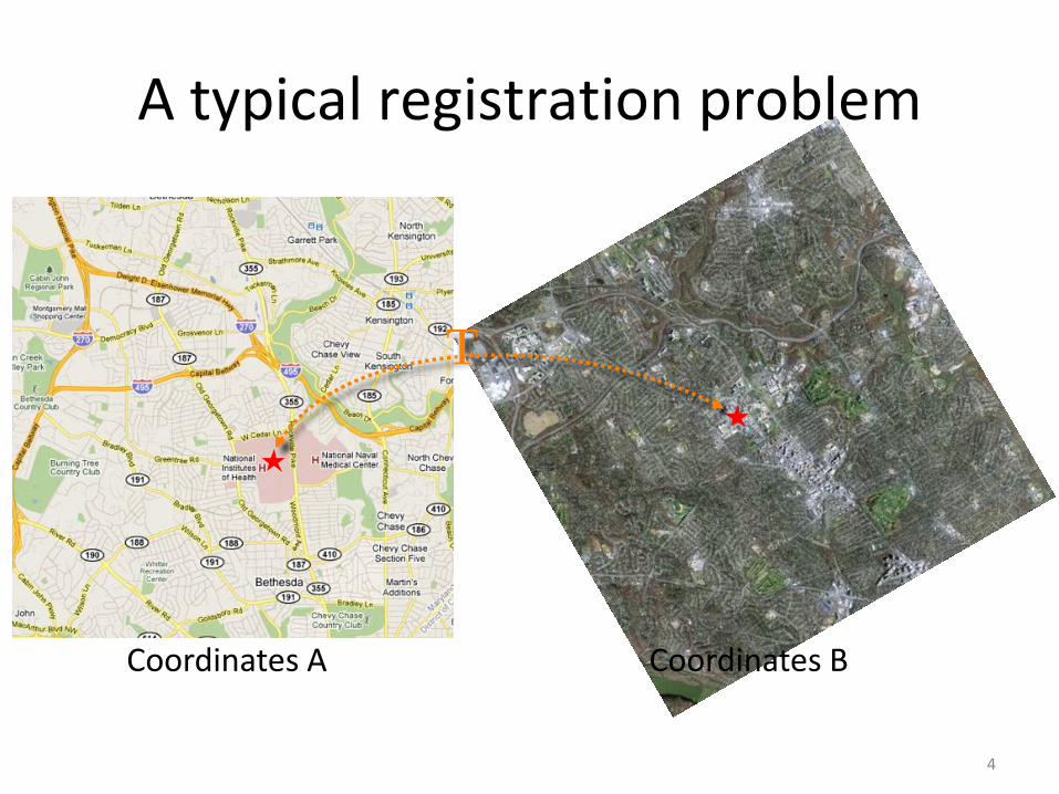
A typical registration problem
Coordinates A Coordinates B
T
5
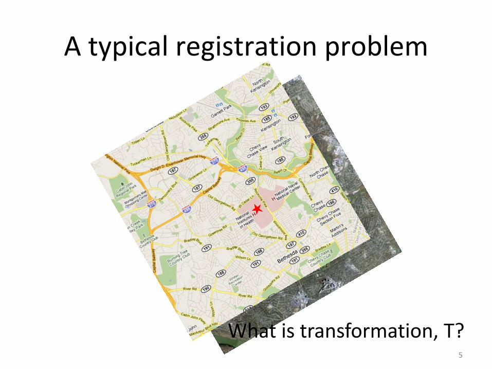
A typical registration problem
What is transformation, T?
6
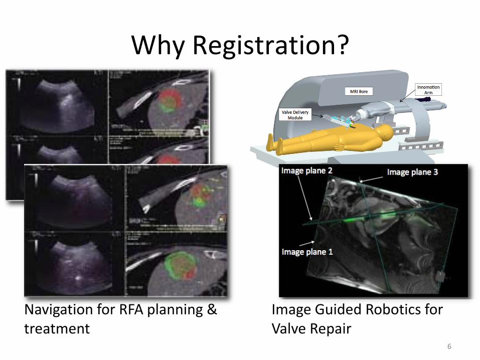
Why Registration?
Navigation for RFA planning & treatment
Image Guided Robotics for Valve Repair

7
Use of PET & Real-time US
Why Registration?Multi modality image fusion
Use of MRI & TRUS

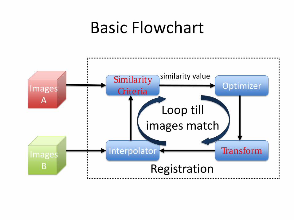
Basic Flowchart
Images A
ImagesB
Interpolator
Similarity Criteria Optimizer
Transform
Loop till images match
similarity value
Registration
Images A
ImagesB
Interpolator
Similarity Criteria Optimizer
Transform
Loop till images match
similarity value
Registration
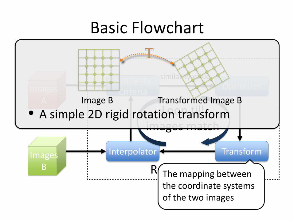
Basic Flowchart
The mapping between the coordinate systems of the two images
T
Image B Transformed Image B
• A simple 2D rigid rotation transform
Images A
ImagesB
Interpolator
Similarity Criteria Optimizer
Transform
Loop till images match
similarity value
Registration
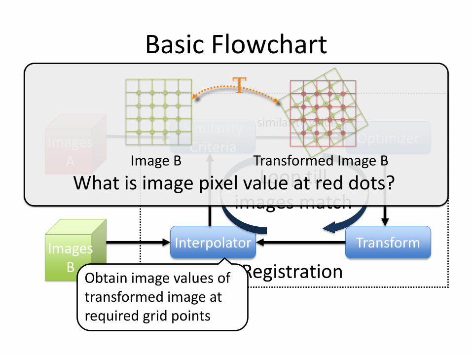
Basic Flowchart
Obtain image values of transformed image at required grid points
T
What is image pixel value at red dots?Image B Transformed Image B

Images A
ImagesB
Interpolator
Similarity Criteria Optimizer
Transform
Loop till images match
similarity value
Registration
Basic FlowchartQuantitatively measures how well the transformed “matches”
• Are these two imagessimilar? alike? homologous?
• Defining the metric is critical• No one solution fits all• Unfortunately, few clear-cut rules
Images A
ImagesB
Interpolator
Similarity Criteria Optimizer
Transform
Loop till images match
similarity value
Registration
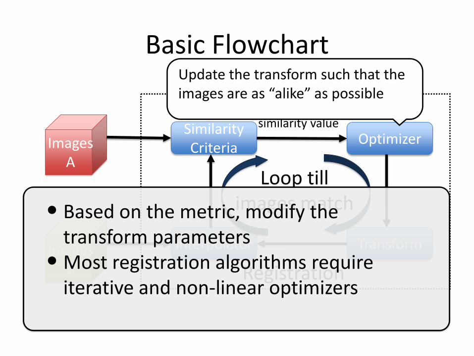
Basic FlowchartUpdate the transform such that the images are as “alike” as possible
• Based on the metric, modify the transform parameters
• Most registration algorithms require iterative and non-linear optimizers

Basic Flowchart
Images A
ImagesB
Interpolator
Similarity Criteria Optimizer
Transform
Loop till images match
similarity value
Registration

Transform
Complexity Rigid
Bsplines
Elastic
Rigid + Shear + Scale
Rigid + Scale
Volume
Thin plateLow High
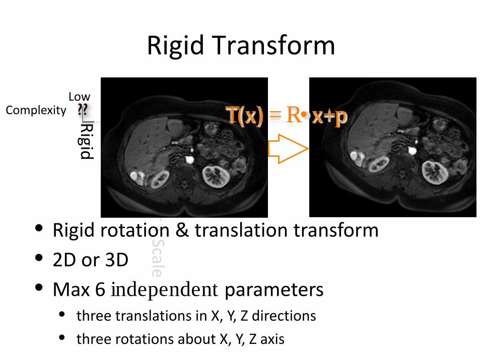
Rigid Transform
Complexity Rigid
Bsplines
Elastic
Rigid + Shear + Scale
Rigid + Scale
Volume
Thin plateLow High
T(x) = R• x+p
• Rigid rotation & translation transform• 2D or 3D• Max 6 independent parameters
• three translations in X, Y, Z directions
• three rotations about X, Y, Z axis

Affine Transform
Complexity Rigid
Bsplines
Elastic
Rigid + Shear + ScaleRigid + Scale
Volume
Thin plateLow High
• Deceptively simple & Tricky• Scaling has non-linear effects• Max 12 parameters
T(x) = A• x+p
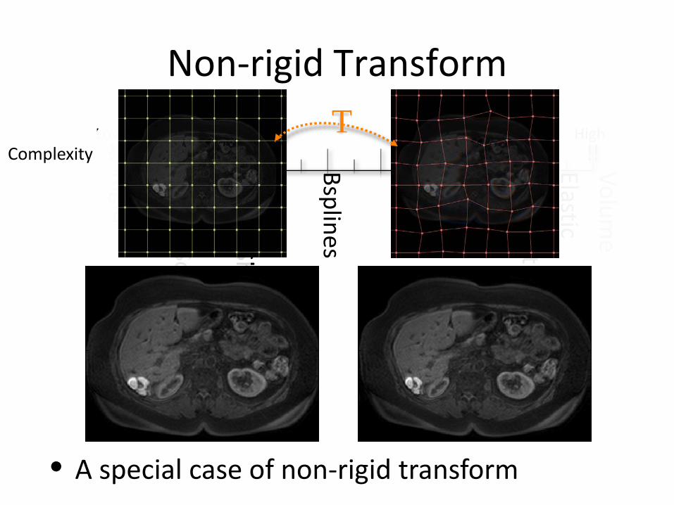
Non-rigid Transform
Complexity Rigid
Bsplines
Elastic
Rigid + Shear + ScaleRigid + Scale
Volume
Thin plateLow HighT
• A special case of non-rigid transform
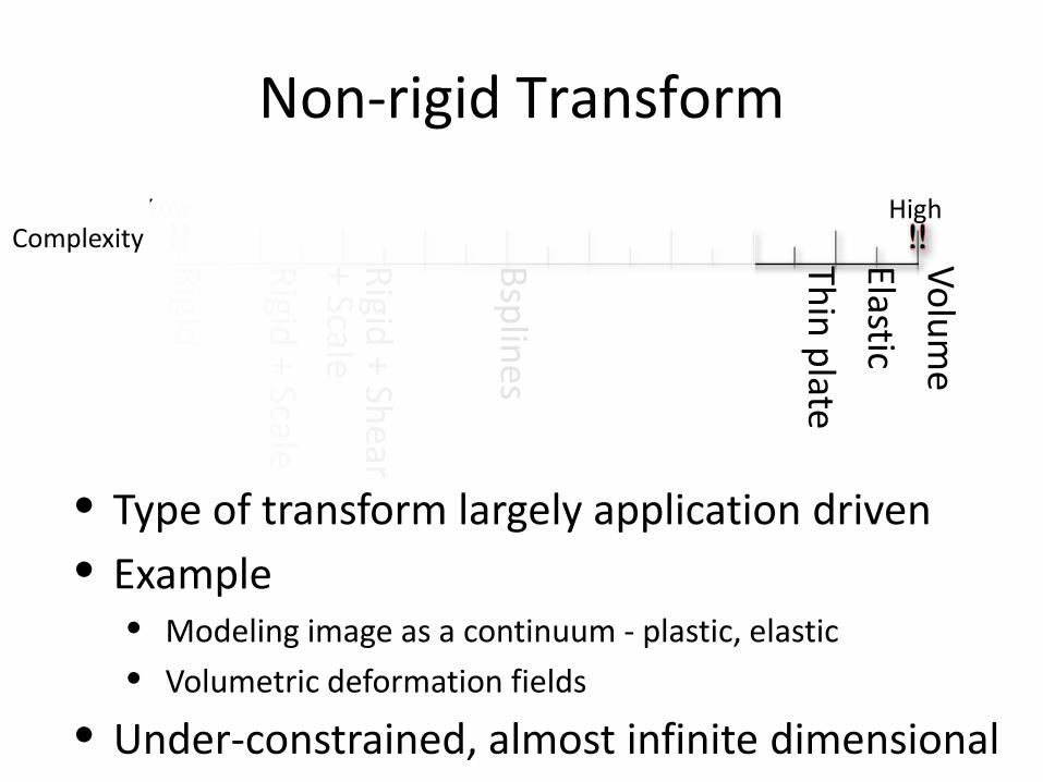
Non-rigid Transform
Complexity Rigid
Bsplines
Elastic
Rigid + Shear + ScaleRigid + Scale
Volume
Thin plateLow High
• Type of transform largely application driven• Example
• Modeling image as a continuum - plastic, elastic
• Volumetric deformation fields
• Under-constrained, almost infinite dimensional
19
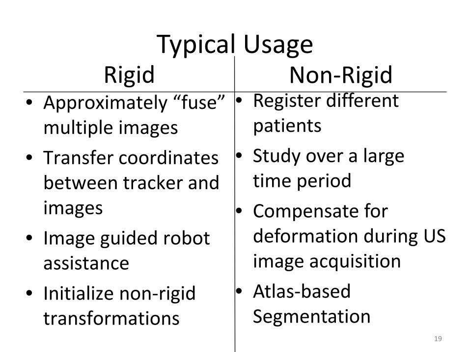
Rigid• Approximately “fuse”
multiple images
• Transfer coordinates between tracker and images
• Image guided robot assistance
• Initialize non-rigid transformations
• Register different patients
• Study over a large time period
• Compensate for deformation during US image acquisition
• Atlas-based Segmentation
Non-RigidTypical Usage
Basic Flowchart
Images A
ImagesB
Interpolator
Similarity Criteria Optimizer
Transform
Loop till images match
similarity value
Registration

Similarity Criteria
•Internal Fiducial•External Fiducial
•Surfaces•Vessels, etc
•Mutual Information•Voxel property
Landmark
Segmentation
Intensity
ComplexityLow
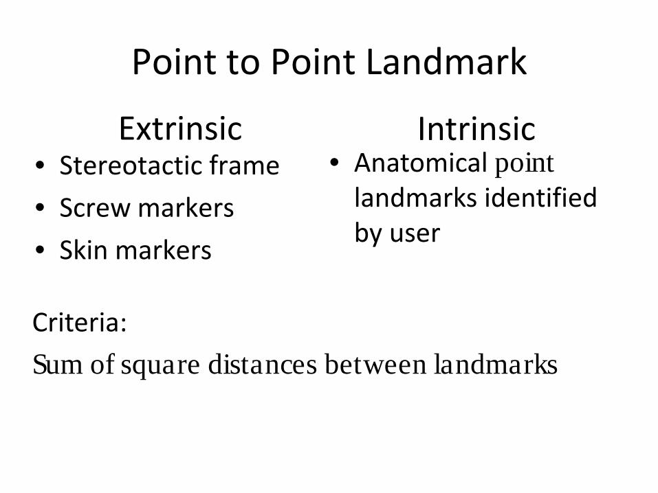
Point to Point Landmark
• Stereotactic frame
• Screw markers
• Skin markers
Extrinsic• Anatomical point
landmarks identified by user
Intrinsic
Criteria:
Sum of square distances between landmarks
Point to Point Landmark Registration
• Requires two sets of N points, N > 3
• Robust, versatile, very fast
• Finding correspondence
• Transfer coordinates between tracker & images
• In practice, limited to rigid/affine transformations
24
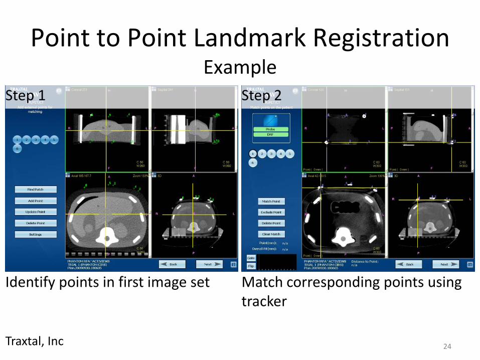
Point to Point Landmark RegistrationExample
Traxtal, Inc
Step 1 Step 2
Identify points in first image set Match corresponding points using tracker
25
Segmentation based• Extract structure (surface, and curve)
• Criteria:– Depends on structure
• Segmentation can be range from automatic-manual– Largely defined by application
– Segmentation effects accuracy
• Applicable to non-rigid, lower computational complexity
26
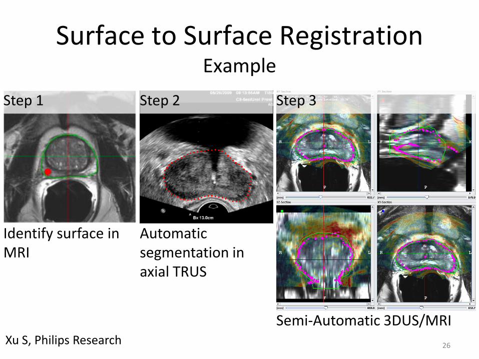
Surface to Surface RegistrationExample
Xu S, Philips Research
Step 1 Step 2 Step 3
Identify surface in MRI
Automatic segmentation in axial TRUS
Semi-Automatic 3DUS/MRI
27
• 2D US/3D MRI registration is sensitive
• Multiple images increase robustness
• Accuracy up to 3mm
• Motion compensation – Using 3D US / TRUS registration
– Improved MRI / US overlap
Surface to Surface RegistrationExample
28
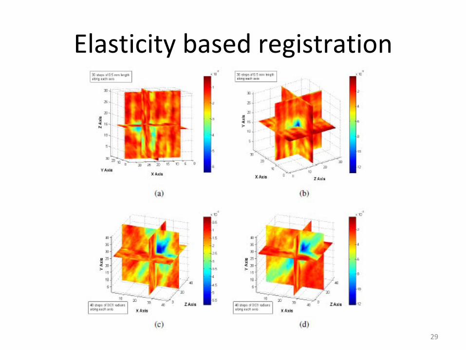
Voxel property
• Derived full image content
• Most flexible
• Considerable computation costs
• Common Criteria:– Absolute difference of intensities
– Mean squares difference of intensities
– Cross-correlation
– Mutual information
29
Elasticity based registration
30
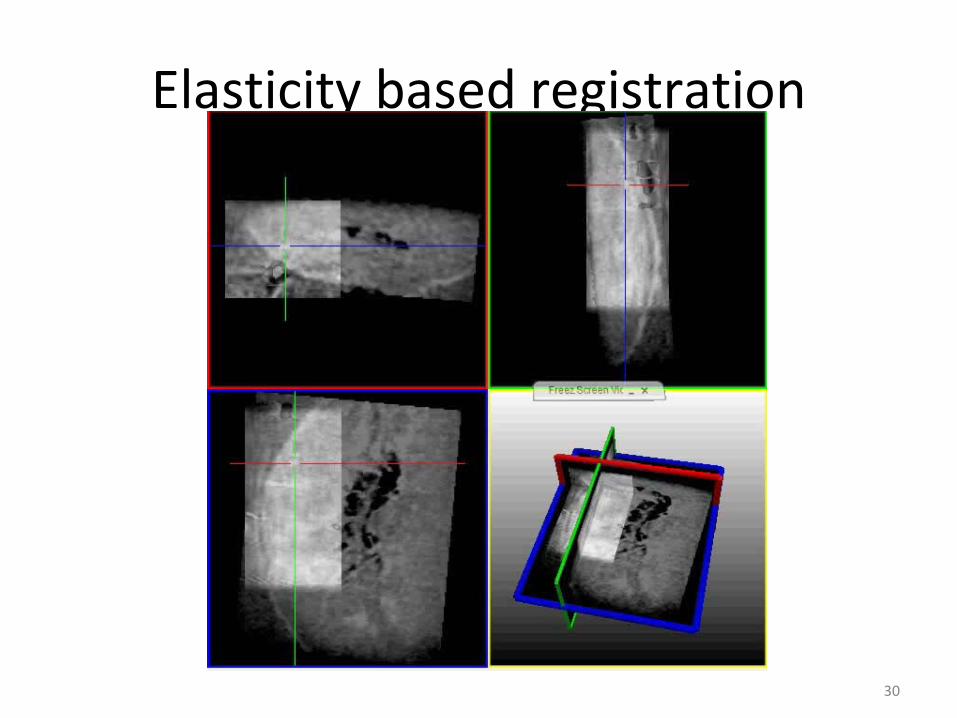
Elasticity based registration

31
3D-3D Rigid RegistrationMean Squares Example
• Series of images at different interval
• Same Imaging modality
• Simple, less computationally expensive

32
3D-3D Deformable Example
Deformable 3D/3D
registration
Update Atlas / statistics
Initial Atlas
(mean shape and shape modes)
Updated Atlas
Subject CT scans
Warped CT scans (to meanshape)
Boot-strapping Loop
Deformed Mesh Instances
Statistical Atlas
Chintalapani G, MICCAI, 2007

33
• Start with a initial approximate atlas, subject CT scans, subject mesh
• Do a Rigid registration
• Obtain a mean CT-like volume, mean shape and modes
3D-3D Deformable Example
Chintalapani G, MICCAI, 2007
Step 1
34
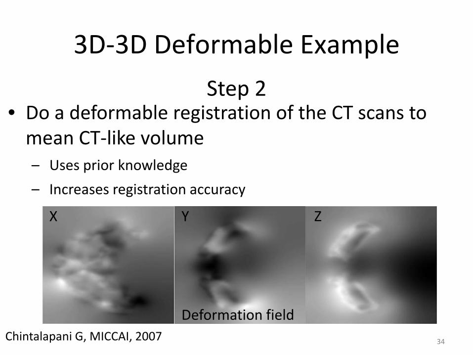
• Do a deformable registration of the CT scans to mean CT-like volume– Uses prior knowledge
– Increases registration accuracy
3D-3D Deformable Example
Chintalapani G, MICCAI, 2007
Step 2
Deformation field
X Y Z

35
• Generate mesh from deformably registered CTs
• Create a new atlas from the deformed mesh
3D-3D Deformable Example
Chintalapani G, MICCAI, 2007
Step 3
36
• Repeat steps 2 & 3 until satisfied
3D-3D Deformable Example
Chintalapani G, MICCAI, 2007
Step 4
37
Summary
• Define the terms registration and image fusion
• Different methods based on need
• Scope and limitations
• Clinical applications
38
References
• Toolkits– ITK (itk.org)
– MITK (mitk.org)
– MeVisLab (mevislab.de)
– Slicer (slicer.org)
• A Survey of Medical Image Registration– Maintz and Viergever, Med. Img. Anal., 1998, 2(1),
1-36
39
References
• Xu S. et al., Real-time MRI-TRUS fusion for guidance of targeted prostate biopsies. Comp Aided Surg. 2008, 13(5), 255-64
• Krücker J. et al, Electromagnetic tracking for thermal ablation and biopsy guidance: clinical evaluation of spatial accuracy. J Vasc Interv Radiol. 2007, 18(9), 1141-50
40
References
• Sadowsky O. et al., Deformable 2D-3D registration of the pelvis with a limited field of view, using shape statistics. MICCAI. 2007, LNCS 4792, 519-26
• Chintalapani G. et al., Statistical Atlases of Bone Anatomy: Construction, Iterative Improvement and Validation. MICCAI. 2007 LNCS 4791, 499-506
• Ellingsen L.M. and Prince JL., Mjolnir: extending HAMMER using a diffusion t f ti d l d hi t