regional reliability reference directory # 1 design and ... · npcc reliability reference directory...
TRANSCRIPT

NPCC Reliability Reference Directory # 1 Design and Operation of the Bulk Power System
This document, when downloaded or printed, becomes UNCONTROLLED. Users should check the NPCC website for the current CONTROLLED version of this document.
1
Regional Reliability Reference Directory # 1 Design and Operation of the Bulk Power System
Task Force on Coordination of Planning Revision Review Record:
December 01, 2009 September 30, 2015
Adopted by the Members of the Northeast Power Coordinating Council, Inc., on December 01, 2009 based on recommendation by the Reliability Coordinating Committee, in accordance with Section VIII of the NPCC Amended and Restated Bylaws dated July 24, 2007 as amended to date.

NPCC Reliability Reference Directory # 1 Design and Operation of the Bulk Power System
This document, when downloaded or printed, becomes UNCONTROLLED. Users should check the NPCC website for the current CONTROLLED version of this document.
2
Revision History
Version
Date
Action
Change Tracking (New, Errata or Revisions)
0 12/1/2009 New 1 4/20/2012 Errata Changes in
Appendices B and E. Errata
2 9/30/2015 TFCP/TFCO Review Revised

NPCC Reliability Reference Directory # 1 Design and Operation of the Bulk Power System
This document, when downloaded or printed, becomes UNCONTROLLED. Users should check the NPCC website for the current CONTROLLED version of this document.
3
Table of Contents
1.0 Introduction .................................................................................................................... 4 1.1 Title: Design and Operation of the Bulk Power System ................................................. 4 1.2 Directory Number: 1 ....................................................................................................... 4 1.3 Objective: ........................................................................................................................ 4 1.4 Effective Date: December 1, 2009 .................................................................................. 4 1.5 Background ..................................................................................................................... 4 1.6 Applicability ................................................................................................................... 5 1.6.1 Functional Entities ...................................................................................................... 5 1.6.2 Applicability of NPCC Criteria: ................................................................................. 5
2.0 Defined Terms ................................................................................................................. 5
3.0 NPCC Full Member, More Stringent Criteria ……………………………………… 6
4.0 Compliance………………………………………………………………………….....11 Table 1 - Planning Design Criteria, Contingency events, Fault type, Performance requirements Table 2 - Planning Criteria: Extreme Contingency and System Conditions, Fault type,
Performance assessments Table 3 - Operating Criteria, Contingency events, Fault type, Performance requirements Appendix A – ERO Standards Appendix B - Guidelines and Procedures for NPCC Area Transmission Review Appendix C - Procedure for Testing and Analysis of Extreme Contingencies Appendix D - Guidelines for Area Review of Resource Adequacy Appendix E - Guidelines for Requesting Exclusions to Simultaneous Loss of Two Adjacent Transmission Circuits on a Multiple Circuit Tower Appendix F - Procedure for Operational Planning Coordination Appendix G - Procedures for Inter Reliability Coordinator Area Voltage Control

NPCC Reliability Reference Directory # 1 Design and Operation of the Bulk Power System
This document, when downloaded or printed, becomes UNCONTROLLED. Users should check the NPCC website for the current CONTROLLED version of this document.
4
1.0 Introduction
1.1 Title: Design and Operation of the Bulk Power System
1.2 Directory Number: 1
1.3 Objective: The objective of this Directory is to provide a “design-based approach” to design and operate the bulk power system to a level of reliability that will not result in the loss or unintentional separation of a major portion of the system from any of the contingencies referenced in Requirement R7 and Requirement R13. The intent of this approach is to avoid instability, voltage collapse and widespread cascading outages. Loss of small portions of a system (such as radial portions) may be tolerated provided these do not jeopardize the reliability of the remaining bulk power system. In NPCC the technique for achieving this level of reliability is to require that the bulk power system be designed and operated to meet the performance requirements for the representative contingencies as specified in this Directory. Simulations shall be used to assess and analyze these contingencies. As a minimum, contingency events shall be applied on bulk power system elements and the resulting performance requirements shall be monitored on the bulk power system. If an entity becomes aware1 of a contingency not on a bulk power system element that results in a significant adverse impact outside the local area, that entity must design and/or operate the system to respect that event. The characteristics of a reliable bulk power system include adequate resources and transmission to reliably meet projected customer electricity demand and energy requirements as prescribed in this document.
1.4 Effective Date: December 1, 2009
1.5 Background
This Directory was developed from the NPCC A-2 criteria document - Basic Criteria for the Design and Operation of Interconnected Power Systems (May 6, 2004 version). Guidelines and Procedures for consideration in the implementation of this Directory are provided in the Appendices.
1 NPCC Members shall strive to meet the reliability objectives in this document. However, there is no affirmative requirement for an NPCC Member to explicitly identify every potential non-BPS contingency that may impact the BPS.

NPCC Reliability Reference Directory # 1 Design and Operation of the Bulk Power System
This document, when downloaded or printed, becomes UNCONTROLLED. Users should check the NPCC website for the current CONTROLLED version of this document.
5
1.6 Applicability
1.6.1 Functional Entities
Reliability Coordinators Transmission Operators Balancing Authorities Planning Coordinators Transmission Planners Resource Planners Generator Owners Transmission Owners
1.6.2 Applicability of NPCC Criteria: The requirements of an NPCC Directory apply only to those facilities defined as NPCC bulk power system elements as identified through the performance based methodology of NPCC Document A-10, “Classification of Bulk Power System Elements,” the list of which is maintained by the NPCC Task Force on System Studies and approved by the NPCC Reliability Coordinating Committee. Requirements to abide by an NPCC Directory may also reside in external tariff requirements, bilateral contracts and other agreements between facility owners and/or operators and their assigned Reliability Coordinator, Planning Coordinator, Transmission Operator, Balancing Authority and/or Transmission Owner as applicable and may be enforceable through those external tariff requirements, bilateral contracts and other agreements. NPCC will not enforce compliance to the NPCC Directory requirements in this document on any entity that is not an NPCC Full Member.
2.0 Defined Terms:
Unless specifically noted in this document terms in bold typeface are defined in the NPCC Glossary of Terms.

NPCC Reliability Reference Directory # 1 Design and Operation of the Bulk Power System
This document, when downloaded or printed, becomes UNCONTROLLED. Users should check the NPCC website for the current CONTROLLED version of this document.
6
3.0 NPCC Full Member Criteria:
Information for Planning and Operational Assessments
R1 Each Functional Entity that owns equipment shall submit verified information
representing the physical or control characteristics of its equipment for system modelling and reliability analysis of the bulk power system in accordance with Requirement R2.
R2 Each Planning Coordinator and Reliability Coordinator shall collect and maintain
information needed for system modelling and reliability analysis of the bulk power system. R2.1 System modelling information shall be submitted to an NPCC Task Force
upon request. R3 Each Reliability Coordinator shall share and coordinate forecast system information
and real-time information to enable and enhance the analysis and modeling of the interconnected bulk power system by security application software on energy management systems.
Resource Adequacy R4 Each Planning Coordinator or Resource Planner shall probabilistically evaluate
resource adequacy of its Planning Coordinator Area portion of the bulk power system to demonstrate that the loss of load expectation (LOLE) of disconnecting firm load due to resource deficiencies is, on average, no more than 0.1 days per year.
R4.1 Make due allowances for demand uncertainty, scheduled outages and
deratings, forced outages and deratings, assistance over interconnections with neighboring Planning Coordinator Areas, transmission transfer capabilities, and capacity and/or load relief from available operating procedures.
R5 Each Planning Coordinator shall report and obtain Reliability Coordinating
Committee (RCC) approval for its Review of Resource Adequacy. Appendix D provides guidance for the Area Review of Resource Adequacy.
R5.1 The Review of Resource Adequacy will be presented to the NPCC Task
Force on Coordination of Planning (TFCP). Comprehensive and Interim reviews shall be presented to the TFCP before the beginning of the first time period covered by the assessment.
R5.2 A Comprehensive Review of Resource Adequacy is required every three
years and will cover a time period of five years. If changes in planned

NPCC Reliability Reference Directory # 1 Design and Operation of the Bulk Power System
This document, when downloaded or printed, becomes UNCONTROLLED. Users should check the NPCC website for the current CONTROLLED version of this document.
7
facilities or forecasted system conditions warrant, TFCP may require a Comprehensive Review of Resource Adequacy in less than 3 years.
R5.3 In subsequent years, each Planning Coordinator shall conduct an Annual
Interim Review of Resource Adequacy that will cover, at a minimum, the remaining years studied in the Comprehensive Review of Resource Adequacy.
R6 Each Reliability Coordinator shall coordinate outages and deratings of resources to
verify adequate resources will be available to meet the forecasted demand and reserve requirements. Appendix F provides guidance for Operational Planning Coordination.
R6.1 A Summer and Winter Reliability Assessment will be presented to the NPCC Task Force on Coordination of Operation (TFCO) every year.
Transmission Planning R7 Each Transmission Planner and Planning Coordinator shall plan its bulk power
system to have sufficient transmission capability to meet the respective requirements as specified in Table 1 while serving forecasted demand.
R7.1 Credible combinations of system conditions which stress the system shall be modelled including, load forecast, inter-Area and intra-Area transfers, transmission configuration, active and reactive resources, generation availability and other dispatch scenarios. All reclosing facilities shall be assumed in service unless it is known that such facilities will be rendered inoperative.
R8 Each Transmission Planner and Planning Coordinator shall assess the impact of the extreme contingencies listed in Table 2. Appendix C provides guidance for testing and analyzing extreme contingencies.
R9 Each Transmission Planner and Planning Coordinator shall assess the impact of extreme system conditions, one condition at a time, subject to contingencies as listed in the “Extreme System Conditions” category of Table 2.
R10 Each Transmission Planner and Planning Coordinator shall have procedures and implement a system design that ensures equipment capabilities are adequate for fault current levels with all transmission and generation facilities in service for all operating conditions which are not prohibited by a procedure and coordinate these procedures with materially affected Transmission Planner and Planning Coordinator Areas.

NPCC Reliability Reference Directory # 1 Design and Operation of the Bulk Power System
This document, when downloaded or printed, becomes UNCONTROLLED. Users should check the NPCC website for the current CONTROLLED version of this document.
8
R11 Each Planning Coordinator shall conduct and obtain Reliability Coordinating Committee (RCC) approval for its Transmission Review. Appendix B provides guidance for Transmission Reviews.
R11.1 A Comprehensive Transmission Review is required at least once every five years or if major or pervasive system changes have occurred. If changes in the planned facilities or forecasted system conditions warrant, the Task Force on System Studies (TFSS) may require a Comprehensive Transmission Review in less than five years.
R11.2 The proposal for the type of annual Transmission Review shall be presented to TFSS by March of the year during which the review is conducted. Approval for the type of Transmission Review shall be obtained from the TFSS. The annual Transmission Review shall be presented to the TFSS by April of the following year.
R11.3 If the results of the Transmission Review indicate that the planned bulk power system will not be in conformance with NPCC Directory #1, the Transmission Review shall incorporate a corrective action plan to achieve conformance.
Special Protection Systems
R12 Each Functional Entity that proposes a new or modified SPS shall consider the
complexity of the scheme and the consequences of correct or incorrect operation as well as its benefits.
R12.1 Provide a rationale and justification to the TFCP including factors such as project delays, temporary construction configurations, unusual combinations of system conditions, equipment outages and infrequent contingencies.
Transmission Operation R13 Each Reliability Coordinator and Transmission Operator shall establish normal
transfer capabilities and emergency transfer capabilities, for its portion of the bulk power system to meet the respective performance requirements for the contingencies as specified in Table 3.
R14 Each Reliability Coordinator and Transmission Operator shall operate to normal transfer capabilities unless an emergency, in accordance with NPCC Directory# 2, is identified.
NPCC Reliability Reference Directory # 1 Design and Operation of the Bulk Power System
This document, when downloaded or printed, becomes UNCONTROLLED. Users should check the NPCC website for the current CONTROLLED version of this document.
9
R15 Each Reliability Coordinator and Transmission Operator shall make system adjustments once an emergency has been identified, including the pre-contingency disconnection of firm load, to avoid exceeding emergency transfer capabilities.
R16 Each Reliability Coordinator and Transmission Operator shall assess the status of the bulk power system immediately after the occurrence of any contingency and prepare for the next contingency as specified in Table 3.
R16.1 Voltage reduction and shedding of firm load shall be deployed to return the system to a secure state, if other system adjustments are not adequate. Voltage reduction need not be initiated and firm load need not be shed to observe a post contingency loading requirement until the contingency occurs, provided that adequate response time for this action is available.
R16.2 System adjustments shall be completed as quickly as possible following any contingency, but within 30 minutes after the occurrence of any contingency specified in Table 3.
R17 Each Reliability Coordinator shall notify the applicable Reliability Coordinators of forced outages of any facility as per the NPCC Transmission Facilities Notification List and of any other condition which may impact inter-Area reliability.
R18 Each Reliability Coordinator shall coordinate scheduled outages of facilities that are on the NPCC Transmission Facilities Notification List sufficiently in advance of the outage to permit the affected Reliability Coordinators to maintain reliability. Appendix F provides guidance for Operational Planning Coordination.
R18.1 Review and update its Facilities Notification List and submit the list to the NPCC Task Force on Coordination of Operation (TFCO) annually.
R19 Each Reliability Coordinator shall coordinate voltage control between Transmission Operator Areas. Appendix G provides guidance for Inter- Reliability Coordinator Area Voltage Control.
R19.1 Metering for reactive power resources and voltage controller status shall be consistent between adjacent Transmission Operators.
R19.2 Upon request from the TFCO, perform an Inter-Area Voltage Control Assessment.

NPCC Reliability Reference Directory # 1 Design and Operation of the Bulk Power System
This document, when downloaded or printed, becomes UNCONTROLLED. Users should check the NPCC website for the current CONTROLLED version of this document.
10
4.0 Compliance:
Compliance with the requirements set forth in this Directory will be in accordance with the NPCC Criteria Compliance and Enforcement Program (CCEP).
NPCC will not enforce a duplicate sanction for the violation of any Directory#1 requirement that is also required for compliance with a NERC Reliability Standard.
___________________________________________________________________________
Prepared by: Task Force on Coordination of Planning Review and Approval: Revision to any portion of this Directory will be posted by the lead
Task Force in the NPCC Open Process for a 45 day review and comment period. Upon addressing all the comments in this forum, the Directory document will be sent to the remaining Task Forces for their recommendation to seek RCC approval.
Upon approval of the RCC, this Directory will be sent to the Full Member Representatives for their final approval if sections pertaining to the Requirements and Criteria portion have been revised. All voting and approvals will be conducted according to the most current "NPCC. Bylaws" in effect at the time the ballots are cast.
Revisions pertaining to the Appendices or other portions of the document such as links, etc., only require RCC approval. Errata may be corrected by the Lead Task Force at any time. This Directory will be updated at least once every three years and as often as necessary to keep it current and consistent with NERC, Regional Reliability Standards and other NPCC documents.
References: NPCC Glossary of Terms Emergency Operations (NPCC Directory #2) Bulk Power System Protection Criteria (NPCC Directory #4) Reserve (NPCC Directory #5) Special Protection Systems (NPCC Directory #7)) Classification of Bulk Power System Elements (A-10)
NPCC Directory #1 Table 1
This document, when downloaded or printed, becomes UNCONTROLLED. Users should check the NPCC website for the current CONTROLLED version of this document.
1
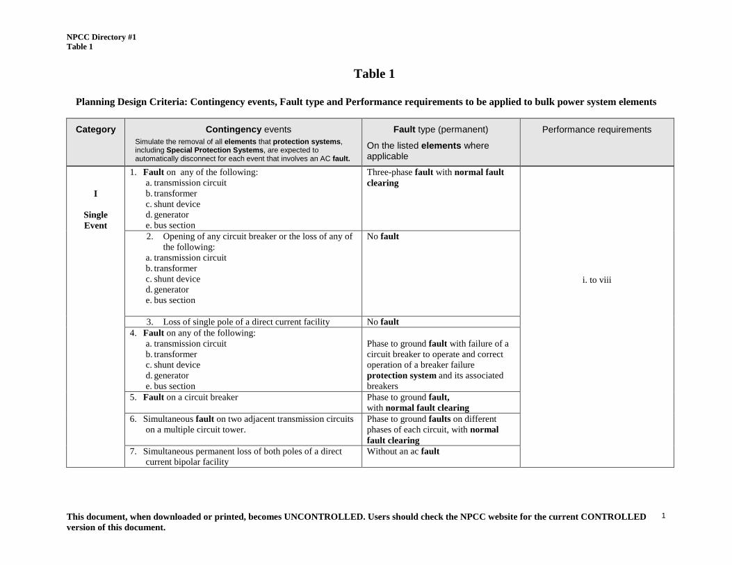
Table 1
Planning Design Criteria: Contingency events, Fault type and Performance requirements to be applied to bulk power system elements
Category Contingency events Simulate the removal of all elements that protection systems, including Special Protection Systems, are expected to automatically disconnect for each event that involves an AC fault.
Fault type (permanent)
On the listed elements where applicable
Performance requirements
I
Single Event
1. Fault on any of the following: a. transmission circuit b. transformer c. shunt device d. generator e. bus section
Three-phase fault with normal fault clearing
i. to viii
2. Opening of any circuit breaker or the loss of any of the following:
a. transmission circuit b. transformer c. shunt device d. generator e. bus section
No fault
3. Loss of single pole of a direct current facility No fault 4. Fault on any of the following:
a. transmission circuit b. transformer c. shunt device d. generator e. bus section
Phase to ground fault with failure of a circuit breaker to operate and correct operation of a breaker failure protection system and its associated breakers
5. Fault on a circuit breaker Phase to ground fault, with normal fault clearing
6. Simultaneous fault on two adjacent transmission circuits on a multiple circuit tower.
Phase to ground faults on different phases of each circuit, with normal fault clearing
7. Simultaneous permanent loss of both poles of a direct current bipolar facility
Without an ac fault

NPCC Directory #1 Table 1
This document, when downloaded or printed, becomes UNCONTROLLED. Users should check the NPCC website for the current CONTROLLED version of this document.
2
Category Contingency events Simulate the removal of all elements that protection systems, including Special Protection Systems, are expected to automatically disconnect for each event that involves an AC fault.
Fault type (permanent)
On the listed elements where applicable
Performance requirements
8. The failure of a circuit breaker to operate when initiated by a SPS after a fault on the following: a. transmission circuit b. transformer c. shunt device d. generator e. bus section
Phase to ground fault, with normal fault clearing
i. to viii
9. The failure of a circuit breaker to operate when initiated by a SPS after opening of any circuit breaker or the loss of any of the following:
a. transmission circuit b. transformer c. shunt device d. generator e. bus section
No fault

NPCC Directory #1 Table 1
This document, when downloaded or printed, becomes UNCONTROLLED. Users should check the NPCC website for the current CONTROLLED version of this document.
3
Category Contingency events Simulate the removal of all elements that protection systems, including Special Protection Systems, are expected to automatically disconnect for each event that involves an AC fault.
Fault type (permanent)
On the listed elements where applicable
Performance requirements
II
Event(s) after a first
loss and after
System Adjustment
1. Following the loss of any critical: a. transmission circuit, b. transformer, c. series or shunt compensating device or d. generator e. Single pole of a direct current facility
and after System Adjustment, Category I Contingencies shall also apply.
Any Category I event as described above.
Performance requirements i to viii apply Area generation and power flows are adjusted between outages by the use of resources available within ten minutes following notification and other system adjustments such as HVDC and phase angle regulator adjustments that can be made within 30 minutes.
Performance Requirements for the contingencies defined in Table 1:
i. Loss of a major portion of the system or unintentional separation of a major portion of the system shall not occur.
ii. Loss of small or radial portions of the system is acceptable provided the performance requirements are not violated for the remaining bulk power system.
iii. Voltages and loadings shall be within applicable limits for pre-contingency conditions.
iv. Voltages and loadings shall be within applicable limits for post-contingency conditions except for small or radial portions of the system as described in ii.
v. The stability of the bulk power system shall be maintained during and following the most severe contingencies, with due regard to successful and unsuccessful reclosing except for small or radial portions of the system as described in ii.
vi. For each of the contingencies that involve fault clearing, stability shall be maintained when the simulation is based on fault clearing initiated by the “system A” protection group and also shall be maintained when the simulation is based on fault clearing initiated by the “system B” protection group. When applying this requirement to contingency event #6, the failure of a protection group shall apply only to one circuit at a time. When evaluating contingency event#4 breaker failure protection is assumed to operate correctly even if only a single breaker failure protection system exists.
vii. Regarding contingency event#6 if multiple circuit towers are used only for station entrance and exit purposes and if they do not exceed five towers at each station, then this condition is an acceptable risk and therefore can be excluded. Other similar situations can be excluded on the basis of acceptable risk, provided that the Reliability Coordinating Committee specifically accepts each request for exclusion. (See Appendix E.)
viii. Transient voltage response shall be within acceptable limits established by the Planning Coordinator and the Transmission Planner except for small or radial portions of the system as described in ii.

NPCC Directory #1 Table 2
This document, when downloaded or printed, becomes UNCONTROLLED. Users should check the NPCC website for the current CONTROLLED version of this document.
1
Table 2
Planning Criteria: Extreme Contingency and System Conditions, Fault type and Performance Assessments to be applied to
bulk power system elements .
Category Contingency events Simulate the removal of all elements that protection systems, including Special Protection Systems, are expected to automatically disconnect for each event that involves an AC fault.
Fault type (permanent) and/or condition applied
On the listed elements where applicable
Performance to be
assessed
Extreme
Contingency
1. Loss of the entire capability of a generating station. No Fault
i, ii, iii
2. Loss of all transmission circuits emanating from a generating station, switching station, substation or dc terminal.
No Fault
3. Loss of all transmission circuits on a common right-of-way. No Fault 4. Fault on of any of the following:
a. transmission circuit b. transformer c. shunt device d. generator e. bus section
Three- phase fault with failure of a circuit breaker to operate and correct operation of a breaker failure protection system and its associated breakers. (with due regard to successful and unsuccessful reclosing.)
5. Fault on a circuit breaker Three-phase fault, with normal fault clearing 6. Sudden loss of a large load or major load center. No Fault 7. The effect of severe power swings arising from disturbances
outside the NPCC’s interconnected systems. Fault applied as necessary.
8. Failure of a Special Protection System, to operate when required following the normal contingencies listed in Table 1, Category I, Single Event.
As listed in Table 1, Category I, Single Event.
9. The operation or partial operation of a Special Protection System for an event or condition for which it was not intended to operate.
No Fault
10. Sudden loss of fuel delivery system to multiple plants, (e.g. gas pipeline contingencies).
No Fault.
Any additional extreme contingencies identified by each Planning Coordinator Area.
Fault applied as necessary.

NPCC Directory #1 Table 2
This document, when downloaded or printed, becomes UNCONTROLLED. Users should check the NPCC website for the current CONTROLLED version of this document.
2
Category Contingency events Simulate the removal of all elements that protection systems, including Special Protection Systems, are expected to automatically disconnect for each event that involves an AC fault.
Fault type (permanent) and/or condition applied
On the listed elements where applicable
Performance to be
assessed
Extreme System
Conditions
Contingency events listed in Table 1, Category I, Single Event Peak load conditions resulting from extreme weather. i (b, c), ii, iii Generating unit(s) fuel shortage (e.g. gas supply adequacy or low hydro) under normal weather peak conditions
i (c), ii, iii
Performance Assessment
i. Model the following pre-contingency conditions:
a. transfers within or between Transmission Planner and Planning Coordinator Areas should be studied at values not expected to be exceeded more than 25% of the time.
b. highly probable dispatch patterns of generation for the transfers being studied
c. appropriate load representation (e.g. active and reactive power as a function of voltage) for transient tests and post transient load flows.
ii. Examine post contingency steady state conditions, as well as stability, overload, cascading outages and voltage collapse to obtain an indication of system robustness and determine the extent of any widespread system disturbance
iii. Where assessment concludes there are serious consequences, an evaluation of implementing a change to design or operating practices to address such contingencies shall be conducted.

NPCC Directory #1 Table 3
This document, when downloaded or printed, becomes UNCONTROLLED. Users should check the NPCC website for the current CONTROLLED version of this document.
1
Table 3
Operating Criteria: Contingency events, Fault type and Performance requirements to be applied to bulk power system elements to establish transfer capabilities. Contingency events
Simulate the removal of all elements that protection systems, including Special Protection Systems, are expected to automatically disconnect for each event that involves an AC fault.
Fault type (permanent)
On the listed elements where applicable
Performance requirements Normal Transfer
Capability Emergency Transfer
Capability (only after an Emergency
is identified)
1. Fault on any of the following: a. transmission circuit b. transformer c. shunt device d. generator e. bus section
Three-phase fault, with normal fault clearing
i, ii, iii, iv, v, vi, vii, ix, x
i, ii, iii, iv, v, vi, vii, ix, xi
2. Opening of any circuit breaker or the loss of any of the following:
a. transmission circuit b. transformer c. shunt device d. generator e. bus section
No fault
3. Loss of single pole of a direct current facility No fault 4. Fault on any of the following: a. transmission circuit b. transformer c. shunt device d. generator e. bus section
Phase to ground fault with failure of a circuit breaker to operate and correct operation of a breaker failure protection system and its associated breakers.
i,ii,iii,iv,v,vi,vii, viii, ix,x
Contingency Events 4 through 8 do not apply after an emergency is
identified.
5. Fault on a circuit breaker Phase to ground fault, with normal fault clearing
6. Simultaneous fault on two adjacent transmission circuits on a multiple circuit tower.
Phase to ground faults on different phases of each circuit with normal fault clearing
7. Simultaneous permanent loss of both poles of a direct current bipolar facility
Without an ac fault

NPCC Directory #1 Table 3
This document, when downloaded or printed, becomes UNCONTROLLED. Users should check the NPCC website for the current CONTROLLED version of this document.
2
8. The failure of a circuit breaker to operate when
initiated by a SPS after a fault on the following:
a. transmission circuit b. transformer c. shunt device d. generator e. bus section
Phase to ground fault, with normal fault clearing
i,ii,iii,iv,v,vi,vii, viii, ix,x
Contingency Events 4 through 8 do not apply after an emergency is
identified.
9. The failure of a circuit breaker to operate when initiated by a SPS after an opening of any circuit breaker or the loss of any of the following:
a. transmission circuit b. transformer c. shunt device d. generator e. bus section
No fault.
Performance Requirements for the contingencies defined in Table 3:
i. Loss of a major portion of the system or unintentional separation of a major portion of the system shall not occur.
ii. Loss of small or radial portions of the system is acceptable provided the performance requirements are not violated for the remaining bulk power system.
iii. Individual Reliability Coordinator Areas shall be operated in a manner such that Contingencies and conditions applied can be withstood without causing significant adverse impact on other Reliability Coordinator Areas.
iv. Voltages and loadings shall be within applicable limits for the pre-contingency conditions.
v. Voltages and loadings shall be within applicable limits for post-contingency conditions except for small or radial portions of the system as described in ii.
vi. The stability of the bulk power system shall be maintained, with due regard to successful and unsuccessful reclosing except for small or radial portions of

NPCC Directory #1 Table 3
This document, when downloaded or printed, becomes UNCONTROLLED. Users should check the NPCC website for the current CONTROLLED version of this document.
3
the system as described in ii.
vii. For each of the contingencies that involve fault clearing, stability shall be maintained when the simulation is based on fault clearing initiated by the “system A” protection group, and also shall be maintained when the simulation is based on fault clearing initiated by the “system B” protection group. When applying this requirement to contingency event#6 the failure of a protection group shall apply only to one circuit at a time. When evaluating contingency event#4 breaker failure protection is assumed to operate correctly even if only a single breaker failure protection system exists
viii. Regarding contingency event#6 if multiple circuit towers are used only for station entrance and exit purposes, and if they do not exceed five towers at each station, then this condition is an acceptable risk and therefore can be excluded. Other similar situations can be excluded on the basis of acceptable risk, provided that the Reliability Coordinating Committee specifically accepts each request for exclusion. (See Appendix E.)
ix. Appropriate adjustments shall be made to Reliability Coordinator Area operation to accommodate the impact of protection group outages, including the outage of a protection group which is a part of a Type I special protection system. For typical periods of forced outage or maintenance of a protection group, it can be assumed, unless there are indications to the contrary, that the remaining protection will function as designed. If the protection group will be out of service for an extended period of time, additional adjustments to operations may be appropriate considering other system conditions and the consequences of possible failure of the remaining protection group.
x. Normal transfer levels shall not require system adjustments before attempting manual reclosing of elements unless specific instructions describing alternate actions are in effect to maintain stability of the bulk power system.
xi. Emergency transfer levels may require system adjustments before attempting manual reclosing of elements to maintain stability of the bulk power system.
Operating to the contingencies listed above in Table 3 is considered to provide an acceptable level of bulk power system security. However, under high risk conditions, such as severe weather, the expectation of the occurrence of contingencies not listed in Table 3 and/or the associated consequences may be judged to be significantly greater. When these conditions exist, consideration should be given to operating in a more conservative manner.

NPCC Directory #1 Appendix A
This document, when downloaded or printed, becomes UNCONTROLLED. Users should check the NPCC website for the current CONTROLLED version of this document.
0
Appendix A - NERC ERO Reliability Standard Requirements:
The NERC ERO Reliability Standards containing requirements associated with this Directory but not necessarily enforceable in all NPCC areas include but may not be limited to:
3.1 EOP-001-2.1b - Emergency Operations Planning 3.2 FAC-011-2 - System Operating Limits Methodology for the Operations Horizon 3.3 IRO-002-2 - Reliability Coordination - Facilities 3.4 IRO-014-1 — Procedures, Processes, or Plans to Support Coordination Between
Reliability Coordinators 3.5 MOD-010-0 - Steady-State Data for Modeling and Simulation of the Interconnected
Transmission System 3.6 MOD-011-0 — Regional Steady-State Data Requirements and Reporting Procedures
FERC approved the withdrawal of MOD-011-0 pursuant to a letter order issued May 1, 2014 in Docket No. RD14-5-000. MOD-011-0 was replaced by MOD-032-1--- Standard subject to future enforcement.
3.7 MOD-012-0 — Dynamics Data for Modeling and Simulation of the Interconnected Transmission System
3.8 MOD-013-1 — RRO Dynamics Data Requirements and Reporting Procedures FERC approved the withdrawal of MOD-013-1 pursuant to a letter order issued May 1, 2014 in Docket No. RD14-5-000. MOD-013-1 was replaced by MOD-032-1--- Standard subject to future enforcement.
3.9 MOD-014-0 — Development of Interconnection-Specific Steady State System Models FERC approved the withdrawal of MOD-014-0 pursuant to a letter order issued May 1, 2014 in Docket No. RD14-5-000. MOD-014-0 was replaced by MOD-032-1--- Standard subject to future enforcement.
3.10 MOD-016-1.1 — Actual and Forecast Demands , Net Energy for Load, Controllable DSM 3.11 TOP-001-1a — Reliability Responsibilities and Authorities 3.12 TOP-002-2.1b— Normal Operations Planning 3.13 TOP-003-1 — Planned Outage Coordination 3.14 TOP-004-2 — Transmission Operations 3.15 TPL-001-0.1 — System Performance Under Normal (No Contingency) Conditions
(Category A) Will be replaced by TPL-001-4 (R2 through R6 and R8). The inactive date for TPL-001.01 is 12/31/2015. Please see the details link for TPL-001-4 for more information.
3.16 TPL-001-4 — Transmission System Planning Performance Requirements 3.17 TPL-002-0b — System Performance Following Loss of a Single Bulk Electric
System Element (Category B) Will be replaced by TPL-001-4 (R2 through R6 and R8). The inactive date for TPL-002.0b is 12/31/2015. Please see the details link for TPL-001-4 for more information.
3.18 TPL-003-0b — System Performance Following Loss of Two or More Bulk Electric System Elements (Category C) Will be replaced by TPL-001-4 (R2 through R6 and R8). The inactive date for TPL-003.0b is 12/31/2015. Please see the details link for TPL-001-4 for more information.
3.19 TPL-004-0a — System Performance Following Extreme Events Resulting in the Loss of Two or More Bulk Electric System Elements (Category D) Will be replaced by TPL-001-4 (R2 through R6 and R8). The inactive date for TPL-004.0a is 12/31/2015. Please see the details link for TPL-001-4 for more information.
3.20 VAR-001-4 — Voltage and Reactive Control

NPCC Directory #1 Appendix B
This document, when downloaded or printed, becomes UNCONTROLLED. Users should check the NPCC website for the current CONTROLLED version of this document.
0
Appendix B - Guidelines and Procedures for NPCC Transmission Reviews
1.0 Introduction
NPCC has established a Reliability Assessment Program to bring together work done by NPCC, Transmission Planners and Planning Coordinators relevant to the assessment of BPS reliability. As part of the Reliability Assessment Program, the Task Force on System Studies (TFSS) is charged on an ongoing basis with conducting periodic reviews of the reliability of the planned bulk power system of each Planning Coordinator Area of NPCC. The purpose of these reviews is to determine whether each Planning Coordinator Area’s planned bulk power transmission system is in conformance with the NPCC Directory #1 Design and Operation of the Bulk Power System. The annual Area Transmission Review required in Requirement R11 is presented for this purpose. It is expected that this Review will cover Directory #1 requirements as they apply to the bulk power system.
2.0 Purpose of Review Presentation The purpose of the presentation associated with an Area Transmission Review is to demonstrate that the Planning Coordinator’s planned bulk power system based on its projection of available demand, transmission, and resources, is in conformance with the Directory #1 criteria. By such a presentation, the Task Force will satisfy itself that the criteria have been met and, in general, that the reliability of the NPCC Interconnected Systems will be maintained.
3.0 Study Year To Be Considered
It is suggested that a study year of 4 to 6 years from the reporting date is a realistic one, both from the viewpoint of minimum lead times required for construction, and the ability to alter plans or facilities. The reviews may be conducted for a longer term beyond 6 years to address identified marginal conditions that may have longer lead-time solutions.
4.0 Types and Frequency of Reviews
As described in Requirement R11, each Planning Coordinator is required to present an annual transmission review to TFSS. However, the review presented by the Planning Coordinator may be one of three types: a Comprehensive (or Full) Review, an Intermediate (or Partial) Review, or an Interim Review. A Comprehensive Review is a thorough assessment of the Planning Coordinator’s entire bulk power system, and includes sufficient analyses to fully address all aspects of an Area Transmission Review as described in Requirement R11. In the years between Comprehensive Reviews, Planning Coordinators may conduct either an Interim Review, or an Intermediate Review, depending on the extent of the Planning Coordinator’s system changes since its last Comprehensive Review. If the system
NPCC Directory #1 Appendix B
This document, when downloaded or printed, becomes UNCONTROLLED. Users should check the NPCC website for the current CONTROLLED version of this document.
1
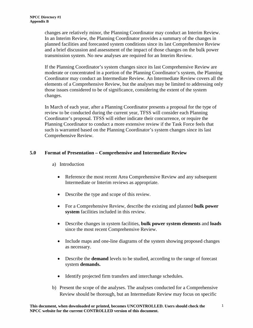
changes are relatively minor, the Planning Coordinator may conduct an Interim Review. In an Interim Review, the Planning Coordinator provides a summary of the changes in planned facilities and forecasted system conditions since its last Comprehensive Review and a brief discussion and assessment of the impact of those changes on the bulk power transmission system. No new analyses are required for an Interim Review. If the Planning Coordinator’s system changes since its last Comprehensive Review are moderate or concentrated in a portion of the Planning Coordinator’s system, the Planning Coordinator may conduct an Intermediate Review. An Intermediate Review covers all the elements of a Comprehensive Review, but the analyses may be limited to addressing only those issues considered to be of significance, considering the extent of the system changes. In March of each year, after a Planning Coordinator presents a proposal for the type of review to be conducted during the current year, TFSS will consider each Planning Coordinator’s proposal. TFSS will either indicate their concurrence, or require the Planning Coordinator to conduct a more extensive review if the Task Force feels that such is warranted based on the Planning Coordinator’s system changes since its last Comprehensive Review.
5.0 Format of Presentation – Comprehensive and Intermediate Review
a) Introduction
• Reference the most recent Area Comprehensive Review and any subsequent Intermediate or Interim reviews as appropriate.
• Describe the type and scope of this review. • For a Comprehensive Review, describe the existing and planned bulk power
system facilities included in this review. • Describe changes in system facilities, bulk power system elements and loads
since the most recent Comprehensive Review. • Include maps and one-line diagrams of the system showing proposed changes
as necessary.
• Describe the demand levels to be studied, according to the range of forecast system demands.
• Identify projected firm transfers and interchange schedules.
b) Present the scope of the analyses. The analyses conducted for a Comprehensive
Review should be thorough, but an Intermediate Review may focus on specific
NPCC Directory #1 Appendix B
This document, when downloaded or printed, becomes UNCONTROLLED. Users should check the NPCC website for the current CONTROLLED version of this document.
2
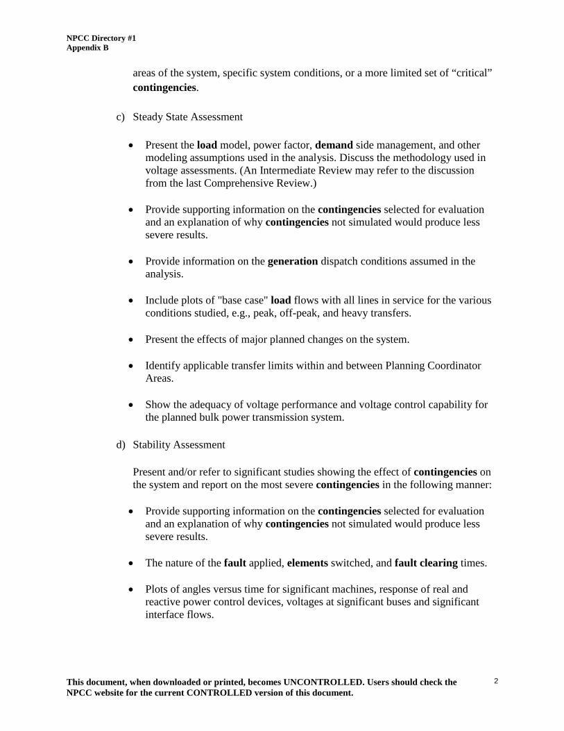
areas of the system, specific system conditions, or a more limited set of “critical” contingencies.
c) Steady State Assessment
• Present the load model, power factor, demand side management, and other
modeling assumptions used in the analysis. Discuss the methodology used in voltage assessments. (An Intermediate Review may refer to the discussion from the last Comprehensive Review.)
• Provide supporting information on the contingencies selected for evaluation
and an explanation of why contingencies not simulated would produce less severe results.
• Provide information on the generation dispatch conditions assumed in the
analysis. • Include plots of "base case" load flows with all lines in service for the various
conditions studied, e.g., peak, off-peak, and heavy transfers. • Present the effects of major planned changes on the system. • Identify applicable transfer limits within and between Planning Coordinator
Areas. • Show the adequacy of voltage performance and voltage control capability for
the planned bulk power transmission system.
d) Stability Assessment
Present and/or refer to significant studies showing the effect of contingencies on the system and report on the most severe contingencies in the following manner: • Provide supporting information on the contingencies selected for evaluation
and an explanation of why contingencies not simulated would produce less severe results.
• The nature of the fault applied, elements switched, and fault clearing times. • Plots of angles versus time for significant machines, response of real and
reactive power control devices, voltages at significant buses and significant interface flows.

NPCC Directory #1 Appendix B
This document, when downloaded or printed, becomes UNCONTROLLED. Users should check the NPCC website for the current CONTROLLED version of this document.
3
For a Comprehensive or Intermediate Review, present the load model and other modeling assumptions used in the analysis. (An Intermediate Review may refer to the discussion from the last Comprehensive Review.)
e) Fault Current Assessment
• Present the methodology and assumptions used in the fault current assessment.
(An Intermediate Review may refer to the discussion from the last Comprehensive Review.)
• Present instances where fault levels exceed equipment capabilities and
measures to mitigate such occurrences. • Present changes to fault levels at stations adjacent to other Planning
Coordinator Areas.
f) Extreme Contingency Assessment
• Present the scope of the analyses including a description of the system conditions assessed. The analyses conducted for a Comprehensive Review should be thorough, but an Intermediate Review may focus on specific areas of the system, specific system conditions, or a more limited set of “critical” contingencies.
• Provide supporting information on the extreme contingencies selected for
evaluation and an explanation of why the remaining contingencies not simulated would produce less severe results.
• Review the results for widespread cascading due to overloads, instability or
voltage collapse caused by extreme contingencies • In the case where contingency assessment reveals serious consequences,
conduct an evaluation of implementing a change to address such contingencies.
g) Extreme System Condition Assessment
• Present the scope of the analyses including a description of the system
conditions assessed. The analyses conducted for a Comprehensive Review should be thorough, but an Intermediate Review may focus on specific areas of

NPCC Directory #1 Appendix B
This document, when downloaded or printed, becomes UNCONTROLLED. Users should check the NPCC website for the current CONTROLLED version of this document.
4
the system, specific system conditions, or a more limited set of “critical” contingencies.
• Provide the rationale for the loss of fuel supply conditions selected for
evaluation and an explanation of why other loss of fuel supply conditions not simulated would produce less severe results.
• Provide supporting information on the contingencies selected for evaluation
and an explanation of why the remaining contingencies not simulated would produce less severe results.
• In the case where extreme condition assessment reveals serious consequences,
conduct an evaluation of implementing measures to mitigate such consequences.
h) Review of Special Protection Systems (SPSs)
• Present the scope of review. A Comprehensive Review should review all the
existing, new and modified SPSs included in its transmission plan. An Intermediate Review may focus on the new and modified SPSs, and just those existing SPSs that may have been impacted by system changes since they were last reviewed.
• Present the need and utilization for Type I and Type II SPSs. For instances
where a SPS utilization is anticipated to increase, the TFSS should inform the Task Force on Coordination of Planning (TFCP) of this finding.
• Review the validity of the classification of Type III SPSs. For instances where
a SPS which was formerly considered to have only local consequences is identified as having the potential for inter- Planning Coordinator Area effects, for the time period being reviewed, the TFSS should notify the Task Force on Coordination of Planning, System Protection and Coordination of Operation. In such instances a complete review of the SPS should be made, as per the Procedure for NPCC Review of New or Modified Bulk Power System Special Protection Systems (SPS) in Directory #7.
i) Review of Dynamic Control Systems (DCSs)
Review of potential consequences of failure or misoperation of Dynamic Control Systems (DCS), as defined in NPCC Document C-33 Procedure for Analysis and Classification of Dynamic Control Systems. For Type I and Type II DCSs, present

NPCC Directory #1 Appendix B
This document, when downloaded or printed, becomes UNCONTROLLED. Users should check the NPCC website for the current CONTROLLED version of this document.
5
and/or refer to appropriate stability studies analyzing the consequences of failure or misoperation in accordance with the Joint Working Group (JWG)-1 report, "Technical Considerations and Suggested Methodology for the Performance Evaluation of Dynamic Control Systems". A Comprehensive Review should address all potentially impactful existing and new DCSs, but an Intermediate Review may focus on new DCSs and only those existing DCSs that may have been impacted by system changes since they were last reviewed.
j) Review of Exclusions to the Directory#1 Criteria
Review any exclusions granted under NPCC Guidelines for Requesting Exclusions to Simultaneous Loss of Two Adjacent Transmission Circuits on a Multiple Circuit Tower (Appendix E). A Comprehensive Review should address all exclusions, but an Intermediate Review may focus on just those exclusions that may have been impacted by system changes since they were last reviewed.
k) Overview Summary of System Performance for Year Studied
6.0 Format of Presentation - Interim Review
a) Introduction of Interim Review
b) Reference the most recent Comprehensive Review and any subsequent Intermediate or Interim Reviews as appropriate.
c) Changes in Facilities (Existing and Planned) and Forecasted System Conditions
Since the Last Comprehensive Review.
• Load Forecast • Generation Resources
• Bulk Power System elements • Transmission Facilities • Special Protection Systems • Dynamic Control Systems • Exclusions
NPCC Directory #1 Appendix B
This document, when downloaded or printed, becomes UNCONTROLLED. Users should check the NPCC website for the current CONTROLLED version of this document.
6
d) Brief Impact Assessment and Overview Summary
The Planning Coordinator will provide a brief assessment of the impact of these changes on the reliability of the interconnected bulk power system, based on engineering judgment and internal and joint system studies as appropriate.
7.0 Documentation
The documentation required for a Comprehensive or Intermediate Review should be in the form of a report addressing each of the items of the above presentation format. The report should be accompanied by the Planning Coordinator’s bulk power system map and one-line diagram, summary tables, figures, and appendices, as appropriate. The report may include references to other studies performed by the Planning Coordinator or by utilities within the Planning Coordinator Area that are relevant to the Area Transmission Review, with appropriate excerpts from those studies. The documentation required for an Interim Review should be in the form of a short summary report (normally not exceeding 5 pages), containing a description of system changes and a brief assessment on their impact on the reliability of the interconnected bulk power system
8.0 Task Force Follow-Up Procedures
8.1 Once a Planning Coordinator has presented its Transmission Review report to the TFSS, TFSS will review the Planning Coordinator’s report and any supporting documentation and consider whether to accept the report as complete and in full conformance with these Guidelines :
a. If the report is found to be unacceptable, TFSS will indicate to the
Planning Coordinator the specific areas of deficiency, and request the Planning Coordinator to address those deficiencies.
b. If there is no concurrence about the results and conclusion(s) of the
Planning Coordinator’s Review, TFSS will indicate to the Planning Coordinator the specific areas of disagreement, and work with the Planning Coordinator to try to achieve concurrence. If agreement has not been reached within a reasonable period of time, TFSS will prepare a summary of the results of its review, and present the summary to the TFCP.
c. If the report is considered as complete and in full conformance with these
Guidelines, TFSS will accept the report.
8.2 If the Area Transmission Review indicates an overall bulk power system reliability concern (not specific to the Planning Coordinator’s planned bulk power transmission system), TFSS will consider what additional studies may be

NPCC Directory #1 Appendix B
This document, when downloaded or printed, becomes UNCONTROLLED. Users should check the NPCC website for the current CONTROLLED version of this document.
7
necessary to address the concern, and prepare a summary discussion and recommendation to the Task Force on Coordination of Planning
8.3 Upon completion of an Area Review, TFSS will report the results of the review to
the Task Force on Coordination of Planning. The TFCP will then review and vote on the completeness and acceptability of the Area Transmission Review and report its finding to the Reliability Coordinating Committee for a final review and approval.

NPCC Directory #1 Appendix C
1
Appendix C - Procedure for Testing and Analysis of Extreme Contingencies 1.0 Introduction
Extreme Contingencies (ECs) are tested "as a measure of system strength" in order to identify potential patterns of weakness in the bulk power transmission system. This procedure for the testing and analysis of ECs should be used when testing ECs for NPCC studies or studies submitted for NPCC review. This procedure applies to transmission planning studies that consider the overall performance of the interconnected systems of the NPCC Planning Coordinator Areas. It principally applies to NPCC - wide studies of the bulk power system and generally does not apply to studies normally conducted by NPCC Transmission Planner and Planning Coordinators that concentrate on individual or a limited number of facilities. This procedure also applies to Area Transmission Reviews, and may be applicable to other studies conducted by the Transmission Planner and Planning Coordinators, and even to individual facility investigations, where such studies and investigations consider the overall performance of the interconnected systems of the NPCC Planning Coordinator Areas. Certain Transmission Planners or Planning Coordinators may elect to completely mitigate the effects of specific ECs. Finally, this procedure should be followed in multi-regional studies in which NPCC is an active participant, to the extent that this is within the scope of such multi-regional efforts.
2.0 Choosing Contingencies for Testing
The ECs are defined as per Requirement R8. Testing should focus on those ECs expected to have the greatest potential effect on the interconnected system. Particular attention should be paid to contingencies which would result in major angular power shifts, e.g., interruption of shorter transmission paths carrying heavy power flows, leaving longer transmission paths as the only remaining paths. Additionally, contingencies which would result in reversal of major power transfers, e.g. loss of major ties in a neighboring region or Area when said region or Area was transferring power away from the area of interest, should be considered for their impact in subjecting the system to severe power swings. In considering specific contingencies to be investigated in an NPCC study, all relevant testing done at the Transmission Planner and Planning Coordinator level should first be reviewed. In general, a contingency in a particular Planning Coordinator Area should be studied, if requested by any other Transmission Planner or Planning Coordinator, based on a reasonable surmise that the requesting Entity may be adversely affected.

NPCC Directory #1 Appendix C
2
3.0 Modeling Assumptions
As referenced in Table 2, performance assessment “i” for Requirement R8, the assumed generation dispatch, transfers levels, load levels and load representation are major considerations in EC tests. It is not the intent to test the worst imaginable extreme, but EC tests should be severe.
The specification of appropriate load representation applies to long term stability tests or post-transient power flows as well as transient stability tests.
4.0 Evaluating Individual Test Results
A question in evaluating the results of a particular test run is - “Does the system "pass" or "fail" for this contingency?” While in the final analysis this is a matter of informed engineering judgment, factors which should be considered include:
1. Lines or transformers loaded above short time emergency ratings, 2. Buses with voltage levels in violation of applicable emergency limits, (which vary
depending on the location within the system), 3. Magnitude and geographic distribution of such overloads and voltage violations
across the system, 4. Transient generator angles, frequencies, voltages and power, 5. Operation of Dynamic Control Systems and Special Protection Systems (SPS), 6. Oscillations that could cause generators to lose synchronism or lead to dynamic
instability, 7. Net loss of source resulting from any combination of loss of synchronism of one or
more units, generation rejection or runback initiated by SPS, or any other defined system separation,
8. Identification of the extent of the Planning Coordinator Area (s) involved for any
indicated instability or islanding (the involvement of more than one Planning Coordinator Area, should be a major consideration),
9. Relay operations or the proximity of apparent impedance trajectories to relay trip
characteristics, 10. The angle across opened breakers,

NPCC Directory #1 Appendix C
3
11. Adequacy of computer simulation models and data.
Finally, a judgment should be attempted as to whether a "failure" is symptomatic of a basic system weakness, or just sensitivity to a particular EC. For example, should failures turn up for several EC tests in a particular part of the system, it is likely that a basic system weakness has been identified. The loss of portions of the system should not necessarily be considered a failed result, provided that these losses do not jeopardize the integrity of the overall bulk power system. NPCC study groups should avoid characterizations like "successful" and "unsuccessful" when commenting on individual runs. Rather, the specific initial conditions directly causing or related to the failure, the complete description of the nature of the failure (e.g., voltage collapse, instability, system separation, as well as the facilities involved), and the extent of potential impact on other Planning Coordinator Areas should be reported.
5.0 Evaluating the Results of EC Tests
EC test reports should focus on those portions of the system in which basic system weaknesses may be developing, rather than on the results of one specific contingency.
Any patterns of weaknesses should be identified, which may include reference to earlier NPCC studies and/or Transmission Planner, Planning Coordinator or member system investigations. There is also a need to distinguish between a "failed" test which indicates sensitivity only to a particular contingency run and a "failed" test which indicates a more general system weakness (always keeping in mind the severity of possible consequences of the contingency). Actions taken by member systems, Transmission Planners or Planning Coordinators to reduce the probability of occurrence or mitigate the consequences of the contingency should also be cited. NPCC follow-up, after publication of a final report, is appropriate only for instances of possible general system weakness. In these instances, the results should be specifically referred to the affected Transmission Planner(s) or Planning Coordinator(s) for further and more detailed investigation with subsequent reporting to NPCC.

NPCC Directory #1 Appendix D
1
Appendix D - Guidelines for Area Review of Resource Adequacy
1.0 Introduction
NPCC has established a Reliability Assessment Program to bring together work done by the NPCC and Planning Coordinators relevant to the assessment of bulk power system reliability. As part of the Reliability Assessment Program, each Planning Coordinator submits to the Task Force on Coordination of Planning its Area Review of Resource Adequacy, which is an annual assessment to demonstrate that the proposed resources of each NPCC Planning Coordinator will meet NPCC resource adequacy planning requirements, consistent with these guidelines. The Task Force is charged, on an ongoing basis, with reviewing and recommending NPCC Reliability Coordinating Committee approval of these reviews of resource adequacy of each Planning Coordinator Area of NPCC. The NPCC role in monitoring conformance with the NPCC Directory #1 - Design and Operation of Bulk Power System is essential because under this criterion, each Planning Coordinator determines its resource requirements by considering interconnection assistance from other Planning Coordinators, on the basis that adequate resources will be available in those Planning Coordinator Areas. Because of this reliance on interconnection assistance, inadequate resources in one Planning Coordinator Area could result in adverse consequences in another Planning Coordinator Area. It is recognized that all Planning Coordinators may not necessarily express their own resource adequacy criterion as stated in Requirements R4, Requirement R5 and Requirement R6 of the Directory #1 criteria. However, the Directory #1 criteria provide a reference point against which a Planning Coordinator’s resource adequacy criterion can be compared.
2.0 Purpose of Presentation
The purpose of the presentation associated with a resource adequacy review is to show that each Planning Coordinator's proposed resources are in accordance with the NPCC Directory #1 - Design and Operation of the Bulk Power System. By such a presentation, the Task Force will satisfy itself that the proposed resources of each NPCC Planning Coordinator will meet the NPCC Resource Adequacy Requirements, as defined NPCC Directory #1, over the time period under consideration.

NPCC Directory #1 Appendix D
2
3.0 Format of Presentation and Report – Comprehensive Review
Each Planning Coordinator should include in its presentations and in the accompanying report documentation, as a minimum, the information listed below. At its own discretion, the Planning Coordinator may discuss other related issues not covered specifically by these guidelines.
3.1 Executive Summary
3.1.1 Briefly illustrate the major findings of the review. 3.1.2 Provide a table format summary of major assumptions and results.
3.2 Table of Contents 3.2.1 Include listing of all tables and figures.
3.3 Introduction 3.3.1 Reference the previous NPCC Area Review. 3.3.2 Compare the proposed resources and load forecast covered in this NPCC
review with that covered in the previous review 3.4 Resource Adequacy Criterion
3.4.1 State the Planning Coordinator's resource adequacy criterion. 3.4.2 State how the Planning Coordinator criterion is applied; e.g., load relief
steps.
3.4.3 Summarize resource requirements to meet the criteria for the time period under consideration. If interconnections to other Planning Coordinators and regions are considered in determining this requirement, indicate the value of the interconnections in terms of megawatts. In the calculation of available resources, supply-side resources from neighboring systems are limited to firm capacity backed purchases.
3.4.4 Provide either an estimate of the resources required to meet the NPCC criteria or
a statement as to the comparison of the two criteria, if the Planning Coordinator criterion is different from the NPCC criterion

NPCC Directory #1 Appendix D
3
3.5 Resource Adequacy Assessment 3.5.1 Evaluate proposed resources versus the requirement to reliably meet
projected electricity demand assuming the Planning Coordinator's most likely load forecast.
3.5.2 Evaluate proposed resources versus the requirement to reliably meet
projected electricity demand assuming the Planning Coordinator’s high load growth scenario.
3.5.3 Describe load and resource uncertainties on projected Planning
Coordinator Area reliability and describe mechanisms to mitigate anticipated material adverse effects on reliability.
3.5.4 Describe anticipated effects from proposed major changes to market rules
on Planning Coordinator Area reliability. 3.5.5 Summarize resource adequacy studies conducted since the previous Area
Review, as appropriate
3.6 Reliability Impacts Due to Environmental Regulations and Fuel Supply Issues. 3.6.1 Discuss anticipated material adverse effects on reliability resulting from
the proposed resources fuel supply and transportation. 3.6.2 Discuss anticipated reliability impacts related to an Area’s compliance
with State, Federal or Provincial requirements (such as environmental, renewable energy, or greenhouse gas reductions).
3.7 Mitigation Measures for Environmental Regulations and Fuel Supply Issues
3.7.1 Describe available mechanisms to mitigate anticipated reliability impacts of resource fuel supply, demand resource response, fuel transportation issues and/or environmental considerations.
4.0 Format of Presentation and Report – Annual Interim Review The Annual Interim Review should include a reference to the most recent Comprehensive Review; a listing of major changes in: facilities and system conditions, load forecast, generation resources availability; related fuel supply and transportation information, environmental considerations, demand response programs, transfer capability and emergency operating procedures. In addition, the assessment should also include a comparison of major changes in market rules, implementation of new rules, locational requirements, and installed capacity requirements. Finally, the report should include a

NPCC Directory #1 Appendix D
4
brief impact assessment and an overall summary. The Planning Coordinator will provide a brief assessment of the impact of these changes on the reliability of the interconnected bulk power system. This assessment should be based on engineering judgment, internal system studies and appropriate joint interconnected studies. To the extent that engineering judgment or existing studies can be used to clearly demonstrate that a Planning Coordinator Area is expected to meet the NPCC resource adequacy criterion, detailed system LOLE studies are not required. The documentation for the Annual Interim Review should be in the form of a summary report (normally not exceeding three to five pages.) Sections A and B should describe the reliability model and program used for the resource adequacy studies discussed in Section 3.5. Section C should describe the Task Force follow-up procedures.
A. Description of Resource Reliability Model
1.1 Load Model
1.1.1 Description of the load model and basis of period load shapes. 1.1.2 How load forecast uncertainty is handled in model. 1.1.3 How the electricity demand and energy projections of interconnected
entities within the Planning Coordinator Area that are not members of the Planning Coordinator Area are addressed.
1.1.4 How the effects (demand and energy) of demand-side management
programs (e.g., conversion, interruptible demand, direct control load management, demand (load) response programs) are addressed.
1.2 Supply Side Resource Representation
1.2.1 Resource Ratings
1.2.1.1 Definitions. 1.2.1.2 Criteria for verifying ratings. Reference NPCC Directory#9
Verification of Gross and Net Real Power Capability and Directory#10 Verification of Gross and Net Reactive Power Capability.
1.2.2 Unavailability Factors Represented

NPCC Directory #1 Appendix D
5
1.2.2.1 Type of unavailability factors represented; e.g., forced outages, planned outages, partial derating, etc.
1.2.2.2 Source of each type of factor represented and whether generic or
individual unit history provides basis for existing and new units 1.2.2.3 Maturity considerations, including any possible allowance for in-
service date uncertainty. 1.2.2.4 Tabulation of typical unavailability factors.
1.2.3 Purchase and Sale Representation
1.2.3.1 Describe characteristics and level of dependability of transactions. 1.2.4 Retirements.
1.2.4.1 Summarize proposed retirements.
1.3 Representation of Interconnected System in Multi-Area Reliability Analysis,
including which Planning Coordinator Areas and regions are considered, interconnection capacities assumed, and how expansion plans of other Planning Coordinators and regions are considered.
1.4 Modeling of Variable and Limited Energy Sources. 1.5 Modeling of Demand Side Resources and Demand (Load) Response Programs.
1.5.1 Description should include how such factors as in-service date uncertainty,
rating, availability, performance and duration are addressed.
1.6 Modeling of all Resources.
1.6.1 Description should include how such factors as in-service date uncertainty; capacity value, availability, emergency assistance, scheduling and deliverability are addressed.
1.7 Other assumptions i.e., internal transmission limitations, maintenance over-runs,
fuel supply and transportation and environmental constraints. 1.8 Incorporate the reliability impacts of market rules.
B. Other Factors, If Any, Considered in Establishing Reserve Requirement
Documentation

NPCC Directory #1 Appendix D
6
The documentation required to meet the requirements of the above format should be in the form of summaries of studies performed within a Planning Coordinator Area, including references to applicable reports, summaries of reports or submissions made to regulatory agencies.
C. Task Force Follow-Up Procedures
Once a specific Planning Coordinator has made a presentation or a series of presentations to the Task Force on Coordination of Planning, the latter shall:
1.1 Prepare a brief summary of key issues discussed during the presentation.
1.2 Note where further information was requested and the results of such further
interrogations. 1.3 Note the specific items that require additional study and indicate the
responsibilities for undertaking these studies.
1.4 Recommend to the Reliability Coordinating Committee whether the Resource Adequacy Review is suitable for approval.

NPCC Directory #1 Appendix E
1
Appendix E - Guidelines for Requesting Exclusions to Simultaneous Loss of Two Adjacent Transmission Circuits on a Multiple Circuit Tower. 1.0 Introduction Directory #1 allows for requests for exclusion from the simultaneous loss of two adjacent
transmission circuits on multiple circuit towers on the basis of acceptable risk. All exclusions must be reviewed by the applicable Task Forces and approved by the Reliability Coordinating Committee (RCC). An acceptance of a request for exclusion is dependent on the successful demonstration that such exclusion is an acceptable risk. These guidelines describe the procedure to be followed and the supporting documentation required when requesting exclusion, and establishes a procedure for periodic review of exclusions of record.
2.0 Documentation The documentation supporting a request for exclusion to the Criteria includes the
following:
2.1 A description of the facilities involved, including geographic location, length and type of construction, and electrical connections to the rest of the interconnected power system;
2.2 Relevant design information pertinent to the assessment of acceptable risk, which
might include: details of the construction of the facilities, geographic or atmospheric conditions, or any other factors that influence the risk of sustaining the loss of adjacent transmission circuits on a multiple circuit tower;
2.3 An assessment of the consequences of the loss of adjacent transmission circuits on
a multiple circuit tower, including, but not limited to, a discussion of levels of exposure and probability of occurrence of significant adverse impact on the bulk power system ;
2.4 For existing facilities, the historical outage performance, including cause, for such
contingencies on the specific facility (facilities) involved as compared to that of other multiple circuit tower facilities;
2.5 For planned facilities, the estimated frequency of adjacent transmission circuit
multiple circuit tower contingencies based on the historical performance of facilities of similar construction located in an area with similar geographic climate and topography.

NPCC Directory #1 Appendix E
2
3.0 Procedure for obtaining an Exclusion
The following procedure is used to obtain an exclusion:
3.1 The entity requesting the exclusion (the Requestor) submits the request and supporting documentation to the Task Force on System Studies (TFSS) after acceptance has been granted by the Requestor’s own Planning Coordinator, if such process is applicable.
3.2 TFSS reviews the request, verifies that the documentation requirements have been met, and determines the acceptability of the request.
3.3 If TFSS deems the request acceptable, TFSS requests the Task Force on Coordination of Planning (TFCP), the Task Force on Coordination of Operation (TFCO), and the Task Force on System Protection (TFSP) to review the request. The Requestor provides copies of the request and supporting documentation to the other Task Forces as directed by TFSS. If additional information is requested by the other Task Forces as part of their assessment, the Requestor provides this information directly to the interested Task Force, with a copy to the TFSS. The other Task Forces review the request and indicate their acceptance or non-acceptance to TFSS.
3.4 If all Task Forces deem the request for exclusion acceptable, the TFSS will
forward a recommendation for approval to the RCC.
3.5 Exclusion requests will be effective upon approval by the RCC.

NPCC Directory #1 Appendix F
1
Appendix F – Procedure for Operational Planning Coordination
1.0 Introduction
The Reliability Coordinators (RC) of the Northeast Power Coordinating Council, Inc. (NPCC) require access to the security data specified in this procedure in order to adequately assess the reliability of the NPCC bulk power system. All users of the electric systems, including market participants, should supply such data to the NPCC Reliability Coordinators. Coordination among and within the Reliability Coordinator Areas (RC Area) of NPCC is essential to the reliability of interconnected operations. Timely information concerning system conditions should be transmitted by the NPCC RC Areas to other RC Areas as needed to assure reliable operation of the bulk power system. One aspect of this coordination is to ensure that adjacent RC Areas and neighboring systems are advised on a regular basis of expected operating conditions, including generator, transmission and system protection, including Type I special protection system, outages that may materially reduce the ability of an RC Area to contribute to the reliable operation of the interconnected system, or to receive and/or render assistance to another RC Area. To the extent practical, the coordination of outage schedules is desirable in order to limit the severity of such impacts.
To ensure that there is effective coordination for system reliability concerns, this document establishes procedures for the exchange of information regarding load/capacity forecasts, including firm sales and firm purchases, generator outage schedules, and transmission outage schedules for those elements that may have an adverse impact on other RC Area(s). It also details general action that may be taken to improve the communication of problems as well as specific topics that may be discussed in regularly scheduled conference calls or ad -hoc conference calls arranged in anticipation of problems such as capacity deficiency or inadequate light load margin in one or more RC Areas.
NPCC participants and other recipients of the information provided by processes in this guideline should adhere to the NPCC Critical Energy Infrastructure Information Non –Disclosure agreement.
2.0 Load/Capacity Forecasts
2.1 Twice yearly by May 15th and November 15th respectively, the Operations Planning Working Group (CO 12) will perform a summer and winter assessment for the next season.
The results will be reviewed by the NPCC TFCO and the NPCC Reliability Coordinating Committee (RCC) during the spring and autumn meetings of both groups and documented in the summer and winter NPCC Reliability Assessment reports.

NPCC Directory #1 Appendix F
2
2.2 Each week, each RC Area will review its weekly net resource capacity margin,
as defined in Attachment A, for the twelve weeks to follow and forward the information to the NPCC Staff for distribution to all NPCC RC Areas. If an NPCC RC Area identifies a deficiency or light load condition, the RC Area should identify the cause(s) and mitigation measures that have been implemented, or will be implemented, to manage the issue.
3.0 Generator Outage Coordination
3.1 Each RC Area should exchange current and expected generator outages that may have a significant impact on an adjacent RC Area or neighboring systems or a significant impact on the transfer capability between RC Areas.
4.0 Transmission Outage Coordination
4.1 Advance Planning of Transmission Facility Outages Each RC should exchange critical transmission element outages as identified in the coordination agreements with their interconnected neighbors, elements identified on the Facilities Notification List and multiple transmission element outages that may have an adverse impact on external energy transfers. Each Reliability Coordinator shall minimize the duration of outages to facilities that impact inter-Reliability Coordinator Areas.
4.2 Facilities Notification List
The NPCC Facilities Notification List, Attachment D, has two components:
1) the NPCC Transmission Facilities Notification List; and 2) the list of NPCC Type I special protection systems.
The Facilities Notification List is developed by each RC Area and specifies all facilities that, if removed from service, may have a significant, direct or indirect impact on another RC Area’s transfer capability. The cause of such impact might include stability, voltage, and/or thermal considerations.
Prior to October 1st of each year, each RC Area will review and update its Facilities Notification List and coordinate necessary changes with other appropriate NPCC RC Areas. Prior to January 1st, and after review by the TFCO, the jointly developed, updated and approved Facilities Notification List will be posted on the NPCC secure website.
It should be noted that revisions to the Facilities Notification List will not follow the NPCC Process for Open Review due to the secure nature of the information

NPCC Directory #1 Appendix F
3
contained, and Attachment D is not openly published with this Procedure.
A temporary reconfiguration of the network may result in an outage to one or more facilities not listed in Attachment D having an impact on other NPCC RC Areas. It is the responsibility of the RC experiencing the condition to notify impacted RCs in a timely manner and provide updated status reports during the condition.
4.3 Notifications of Transmission Element Outages:
4.3.1 Notification requirements for Transmission Element Outages should be defined in interconnection coordination agreements. The time frames identified below are the minimum notification requirements.
4.3.2 Reliability Coordinators will advise affected RCs of all planned and
unplanned outages of elements on the Facilities Notification List and those multiple transmission element outages that may have an adverse impact on external energy transfers.
All outages to equipment listed in the Facilities Notification List and those multiple transmission element outages that may have an adverse impact on external energy transfers should be planned with as much advance notice as practical.
Normally, notification for outages on elements covered by this instruction will be submitted to the appropriate RC Areas at least two (2) working days prior to the time the element is to be taken out of service.
When an RC Area receives an outage notification from another RC Area, prompt attention will be given to the notification and appropriate comments rendered.
4.3.3 An RC Area will not normally remove from service any transmission
elements, which might have a reliability impact on an RC Area without prior notification to and appropriate review by that RC Area. In the event of an emergency condition, each RC Area may take action as deemed appropriate. Other RC Areas should be notified immediately.
An RC Area will make every effort to reschedule routine (non-emergency) transmission outages that severely degrade the reliability of an adjacent RC Area or neighboring system.
4.3.4 Each RC Area will advise the other affected RC Areas of any protection
outage associated with RC Area tie line facilities Coordination agreements may identify additional reporting requirements associated with protection outages.

NPCC Directory #1 Appendix F
4
5.0 Specific Communications
Conditions in an RC Area that may have an impact on another RC Area should be communicated in a clear and timely manner. Specific communications are conducted as follows:
5.1 Weekly
Each Thursday a conference call will be initiated by the NPCC Staff to discuss operations expected during the seven-day period starting with the following Sunday. Operations personnel from the NPCC RC Areas and, as necessary, adjacent RC Areas will participate. In advance of the conference call, each RC Area will prepare the data specified in Attachments A and B, and forward it to the NPCC Staff a minimum of one hour in advance of the scheduled call. The completed “NPCC Weekly Conference Call Generating Capacity Worksheet,” Attachment B, together with the list of “Twelve Weeks Projections of Net Margins,” will be forwarded to the conference call participants by the NPCC Staff.
Each RC will review its weekly capacity margins for the next twelve week period. If a deficiency or light load condition is identified, the RC will identify the cause of the deficiency or light load condition and discuss proposed mitigation measures.
The NPCC Staff will prepare Conference Call Notes that will be forwarded to the conference call participants and members of the TFCO by the following Friday afternoon.
Items of particular concern that should be addressed during the weekly conference call are described in Attachment C.
5.2 Emergency Preparedness Conference Call
Whenever adverse system operating or weather conditions are expected, any RC Area may request the NPCC Staff to arrange an Emergency Preparedness Conference Call (NPCC Document C-01) to discuss operating details with appropriate operations management personnel from the NPCC RC Areas and neighboring systems.
5.3 Daily Conference Calls
Each of the NPCC Reliability Coordinator Area control rooms participate in a regularly scheduled daily conference call. The goal of this call is to alert NPCC Reliability Coordinators of any potential emerging problems. Subjects for discussion are limited to credible events which could impact the ability of a

NPCC Directory #1 Appendix F
5
Reliability Coordinator to serve its load and meet its operating reserve obligations, or which would impose a burden to the Interconnection.

NPCC Directory #1 Appendix F
6
Procedure for Operational Planning Coordination – Attachment A
Load and Capacity Table Instructions
and Generating Capacity Worksheet Instructions
Week Beginning The seven day period for which data is to be
reported is defined as starting with the Sunday following the conference call through the following Saturday.
Installed Generating Capacity (Line Item 1)
Include all available generation at its maximum demonstrated capability for the appropriate seasonal capability period.
Other Generating Capacity(Line Item 2) Include all available generation not included in
Item#1. This item includes, but is not limited to, co-generators, small power producers and all other non-utility electricity producers, such as exempt wholesale generators who sell electricity.
Firm Purchases (Line Item 3) Include only those transactions where capacity
is delivered. Exclude “energy only” transactions. Firm Sales (Line Item 4) Include only those transactions where capacity
is delivered. Exclude “energy only” transactions. Net Capacity (Line Item 5) Add Installed Generating Capacity and Firm
Purchases. Subtract Firm Sales. (Line 1+Line 2-Line3)
Peak Load Forecast (Line Item 6) The peak load forecast along with the day during
which the peak is expected to occur should be the best estimate of the RC Area’s maximum peak load exposure anticipated for the week reported.
Available Reserve (Line Item 7) Subtract Peak Load Forecast from Net
Capacity. (Line 4-Line5.) Demand Side Management (Line Item 8) Include only maximum capability which can be
obtained by operator initialization within four (4) hours.

NPCC Directory #1 Appendix F
7
Attachment A (continued)
Known Unavailable Capacity (Line Item 9)
Include all known outages, as well as those deratings or unit outages presently forced out, unavailable, on extended cold standby or which are anticipated to remain out of service. This would also include capacity unavailable due to transmission constraints.
Net Reserve (Line Item 10) Available Reserve plus Demand Side
Management minus Known Unavailable Capacity. (Line 6+Line 7-Line 8)
Required Operating Reserve (Line Item 11)
The methodology used by each RC Area in calculating operating reserves should, at a minimum, meet the requirements of NPCC Directory # 5, “Reserve.” Methodologies differing from the Directory #5 requirements should be clarified in Attachment B, “NPCC Weekly Conference Call Generating Capacity Worksheet,” under the tab for “Operating Reserve.”
Gross Margin (Line Item 12) Subtract Required Operating Reserve from Net
Reserve. (Line 9-Line 10) Unplanned Outages (Line Item 13) Estimate the amount of generating capacity
which will be unavailable. This quantity should be based on historical averages for forced outages and deratings.
Net Resource Capacity Margin (Line Item 14)
Subtract Unplanned Outages from Gross Margin. A positive value reflects surplus reserve. A negative value reflects a deficiency. (Line 11-Line 12)
Forecast High / Low Temperatures and Days (Line Item 15)
Include the expected high and low temperatures for the RC Area for the week, and indicate the day on which they are expected to occur.

NPCC Directory #1 Appendix F
8
Attachment A (continued) Seasonal High / Low Temperatures (Line Item 16)
Include the expected high and low forecast seasonal temperatures for the RC Area.
Minimum Load Forecast (Line Item 17) The minimum load forecast, indicating the day on
which it is expected to occur should be the best estimate of the RC Area’s minimum load exposure anticipated for the week reported.
Minimum Resources (Line Item 18) The Minimum Resources are the Reliability
Coordinator Area’s total expected on-line generator minimum output capability and must-take purchases.
Light Load Margin (Line Item 19) Subtract Minimum Resources from Minimum
Load Forecast. A negative number indicates a light load condition. (Line 17-Line 18)

NPCC Directory #1 Appendix F
9
Procedure for Operational Planning Coordination – Attachment B
NPCC Weekly Conference Call Generating Capacity Worksheet The “NPCC Weekly Conference Call Generating Capacity Worksheet” is an active spreadsheet used each week to assist in the calculation of the data discussed during the weekly conference call. A blank template is available from the NPCC office.

10
Procedure for Operational Planning Coordination - Attachment C
CONDITIONS FOR DISCUSSION
Items of particular concern that should be discussed during a conference call can include, but are not limited to, the following:
• anticipated weather;
• largest first and second contingencies;
• operating reserve requirements and expected available operating reserve;
• capacity deficiencies;
• potential fuel shortages or potential supply disruptions which could lead to energy
shortfalls;
• light load margins;
• general and specific voltage conditions throughout each system or RC Area;
• status of short term contracts and other scheduled arrangements, including those that impact on operating reserves;
• additional capability available within twelve hours and four hours;
• generator outages that may have a significant impact on an adjacent RC Area or
neighboring system;
• transmission outages that may have an adverse impact on external energy transfers;
• potential need for emergency transfers;
• expected transfer limits and limiting elements;
• a change or anticipated change in the normal operating configuration of the
system, such as the temporary modification of relay protection schemes so that the usual and customary levels of protection will not be provided, or the arming of special protection systems not normally armed, or the application of abnormal operating procedures; and
• update of the abnormal status of NPCC Type I special protection systems forced
out of service

11
Attachment D
NPCC Facilities Notification List Attachment D is not publicly available due to the confidential nature of the information presented.

NPCC Directory #1 Appendix G
1
Appendix G - Procedures for Inter Reliability Coordinator Area Voltage Control 1.0 Introduction
This Procedure provides general principles and guidance to Reliability Coordinators and Transmission Operators for effective inter- Transmission Operator Area voltage control, consistent with the NPCC, Directory #1, “Design and Operation of the Bulk Power System”. Specific methods to implement this Procedure may vary among Reliability Coordinators and Transmission Operators, depending on local requirements. Coordinated inter- Transmission Operator Area voltage control is necessary to regulate voltages to protect equipment from damage and prevent voltage collapse. Coordinated voltage regulation reduces electrical losses on the network and lessens equipment degradation. Local control actions are generally most effective for voltage regulation. Occasions arise when adjacent Reliability Coordinators and Transmission Operators can assist each other to compensate for deficiencies or excesses of reactive power and improve voltage profiles and system security.
2.0 Principles
Each Reliability Coordinator and Transmission Operator operates, in accordance with NPCC, Directory #1, “Design and Operation of the Bulk Power System” criteria, their own individual or joint operating policies, procedures and applicable interconnection agreements. Adjacent Reliability Coordinators and Transmission Operator should be familiar with the respective criteria and procedures of their neighboring Reliability Coordinators and Transmission Operator Areas, and should mutually agree upon procedures for inter- Transmission Reliability Coordinator and Operator Area voltage control. In the event the system state changes to a condition that requires a voltage or reactive corrective action, the Reliability Coordinator and Transmission Operator for the Area in which the condition is originating from should immediately take corrective action. If the corrective control actions are ineffective, or the Reliability Coordinator and Transmission Operator for the Area have insufficient reactive resources to control the problem, assistance may be requested from other Reliability Coordinators and Transmission Operator Areas. Whether inter- Reliability Coordinator and Transmission Operator Area voltage control is carried out through specific or general procedures, the following should be considered and implemented if applicable:
2.1 To effectively coordinate voltage control, location and placement of metering for
reactive power resources and voltage controller status should be the same between adjacent Reliability Coordinators and Transmission Operator Areas;
2.2 the availability of voltage regulating transformers in the proximity of tie lines;
NPCC Directory #1 Appendix G
2
2.3 voltage levels, limits, and regulation requirements for stations on either side of an
inter- Reliability Coordinator and Transmission Operator Area interface; 2.4 the circulation of reactive power (export at one tie point in exchange for import
at another); 2.5 tie line reactive losses as a function of active power transfer; 2.6 the sharing of the reactive requirements of tie lines and series regulating
equipment (either equally or in proportion to line lengths, etc.); 2.7 the transfer of reactive power from one Reliability Coordinator and Transmission
Operator Area to another 2.8 reactive reserve of on-line generators; 2.9 shunt reactive device availability and switching strategy; 2.10 static VAR compensator availability, reactive reserve, and control strategy; 2.11 each Reliability Coordinator and Transmission Operator Area should anticipate
voltage trends and initiate corrective action in advance of critical periods of heavy and light loads.
2.12 Each Reliability Coordinator and Transmission Operator Area should maintain a
mix of static and dynamic resources, including reactive reserves
3.0 Procedure for Triennial Monitoring and Reporting of Inter-Area Voltage Control
3.1 On, or shortly before, the first of July, the Task Force Coordination of Operations
(TFCO) Secretary will write to each TFCO member, requesting a written response by the end of July in the form of:
a) A copy of any new or revised procedures, principles, or understandings (such
as minutes of an operating committee meeting between Reliability Coordinators and Transmission Operator Areas) between the reporting Reliability Coordinator and adjacent Reliability Coordinators, or,
b) a response indicating no change to existing procedures, principles, or
understandings currently on file at NPCC. 3.2 The TFCO Secretary will summarize the responses and will forward it to TFCO
members at least two weeks prior to the October TFCO meeting.

NPCC Directory #1 Appendix G
3
3.3 Following TFCO review and acceptance of the responses, the TFCO Chairman
will forward the summary to the Chairman of the Reliability Coordinating Committee (RCC) for informational purposes. This will normally be forwarded three weeks prior to the next regularly scheduled RCC meeting.