refuse trailers - east manufacturing...tarping is mandatory for refuse trailers in many states....
TRANSCRIPT

OPERATION MANUAL
Refuse Trailers
East Refuge Ops Manual Cover2.indd 1 7/15/19 11:49 AM

INT
RO
DU
CT
ION
OP
ER
AT
ION
PR
EV
EN
TIV
EM
AIN
TE
NA
NC
EC
OM
PO
NE
NT
OP
ER
AT
ION
NH
TS
AIN
FOR
MA
TIO
NW
AR
RA
NT
Y

Contents Page 3
Contents
Contents ............................................................................................................... 3
Introduction .......................................................................................................... 4 Safety Information .......................................................................................... 4 Decals ............................................................................................................ 5
Operation ............................................................................................................. 7 Normal Trailer Use .......................................................................................... 7 Pre-Trip Inspection Checklist ......................................................................... 8 Coupling and Uncoupling Procedures ........................................................... 9 Coupling Preparation .............................................................................. 9 Coupling Procedure ................................................................................ 9 Uncoupling Preparation ........................................................................ 10 Uncoupling Procedure .......................................................................... 10 Loading Procedure ....................................................................................... 11 Unloading Procedure ................................................................................... 11
Preventive Maintenance ................................................................................... 14 Weekly Inspection and Service .................................................................... 14 Monthly Inspection ....................................................................................... 16
Component Operation ...................................................................................... 17 General Instructions ..................................................................................... 17 Landing Gear (2-Speed) ............................................................................... 17 Lubrication ............................................................................................ 18 Suspensions ................................................................................................. 18 Air Springs............................................................................................. 18 Shock Absorbers .................................................................................. 19 Air Controls ........................................................................................... 20 Height Control Valve ............................................................................. 20 Disc Wheels ................................................................................................. 21 Changing Flat Tire ................................................................................. 21
NHTSA Information ........................................................................................... 22
East Refuse Limited Warranty .......................................................................... 23
Page 4
INT
RO
DU
CT
ION
IntroduCtIon
This manual:
• Describes the proper procedures that must be considered prior to operating any of East Manufacturing Corporation’s refuse trailers.
• Contains safety information, instructions and preventive maintenance checks that the operator should perform periodically.
• Should be kept with the trailer at all times.
• East manuals are available online at EastMfg.com.
East reserves the right to change its products and documents without notice.
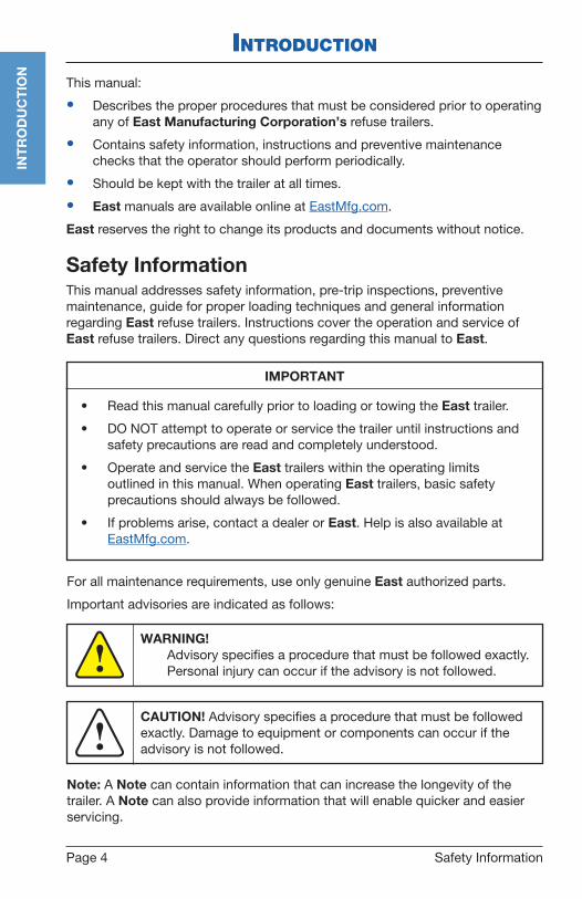
Safety InformationThis manual addresses safety information, pre-trip inspections, preventive maintenance, guide for proper loading techniques and general information regarding East refuse trailers. Instructions cover the operation and service of East refuse trailers. Direct any questions regarding this manual to East.
Safety Information
IMPORTANT
• Read this manual carefully prior to loading or towing the East trailer.
• DO NOT attempt to operate or service the trailer until instructions and safety precautions are read and completely understood.
• Operate and service the East trailers within the operating limits outlined in this manual. When operating East trailers, basic safety precautions should always be followed.
• If problems arise, contact a dealer or East. Help is also available at EastMfg.com.
For all maintenance requirements, use only genuine East authorized parts.
Important advisories are indicated as follows:
WARNING! Advisory specifies a procedure that must be followed exactly.
Personal injury can occur if the advisory is not followed. !CAUTION! Advisory specifies a procedure that must be followed exactly. Damage to equipment or components can occur if the advisory is not followed.!
Note: A Note can contain information that can increase the longevity of the trailer. A Note can also provide information that will enable quicker and easier servicing.
Page 5
INT
RO
DU
CT
ION
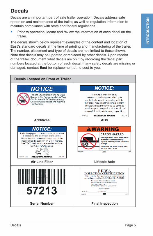
Decals
DecalsDecals are an important part of safe trailer operation. Decals address safe operation and maintenance of the trailer, as well as regulation information to maintain compliance with state and federal regulations.
• Prior to operation, locate and review the information of each decal on the trailer.
The decals shown below represent examples of the content and location of East’s standard decals at the time of printing and manufacturing of the trailer. The number, placement and type of decals are not limited to those shown. Note that decals may be updated or replaced by other decals. Upon receipt of the trailer, document what decals are on it by recording the decal part numbers located at the bottom of each decal. If any safety decals are missing or damaged, contact East for replacement at no cost to you.
Decals Located on Front of Trailer
Air Line Filter Liftable Axle
Additives ABS
Serial Number Final Inspection

Page 6
INT
RO
DU
CT
ION
Decals
Decals Located on Side of Trailer
Beam WarningShakeproof Bolt
Page 7
OP
ER
AT
ION
operatIon
Normal Trailer UseEast trailers are designed for operation within the legal highway speed limits and tire manufacturer speed limit on reasonable road surfaces for the type of service it was built to perform in accordance with the following:
The trailer was built to carry cargo within the limitations of two weight ratings listed on the VIN plate. The VIN plate is located on the main chassis rail, roadside, directly to the rear of the landing gear. These weight ratings are:
• GAWR (gross axle weight rating) – The structural capability of the lowest rated member of the running gear components: suspension and spring system, hubs, wheels, drums, rims, bearings, brakes, axles or tires.
• GVWR (gross vehicle weight rating) – The structural capability of the trailer when supported by the upper coupler assembly and axles with the load uniformly distributed throughout the cargo space.
Normal Trailer Use
WARNING!• Walk carefully on the trailer. The floor or catwalk may be
slippery. Enter and leave the trailer from the mandoor or ladder mounted on the body of the trailer. Advise others of these precautions.
• Operation of this trailer outside the limitation of this manual or against any federal law will void any responsibility of East for any of the results.
!
CAUTION! The maximum load indicated on the VIN plate may or may NOT be a legal load on the highway you plan to use. !

Page 8
OP
ER
AT
ION
Pre-Trip Inspection Checklist
Pre-Trip Inspection Checklist
Driver pre-trip inspections must be completed before the first trip of each day and each subsequent trip during the day. Each pre-trip inspection will visually inspect for deficiencies, including the following:
Verify that all lights function properly.
Check that all reflectors are in place and not obscured.
Check that tailgate latches open and close.
Make sure tailgate latching linkage is properly adjusted. When latched, the locking cams must pass over center on both tailgate latches.
Inspect for any apparent damage.
Visually inspect all leaf springs for cracked or broken leaf and equal arch.
Be sure leaf springs are secured within the hangers and equalizers.
Check that all air springs are inflated, and shock absorber fasteners are tight.
Look for oil, water or fuel leaks.
Verify that the spare tire is secure in the carrier to avoid tire carrier damage. Be sure the tire carrier is securely bolted in place.
Visually check the brake pads or shoes for wear.
Make sure there is sufficient hydraulic oil in the hydraulic tank.
Check for chafed hoses or cracked fittings.
Examine the landing gear for proper road clearance and ensure the crank handle is securely stowed.
Verify the kingpin is engaged and locked within the fifth wheel.
By actuation, verify that the brake system is in proper working order, and listen for air leaks when the system is charged.
Check air pressure in all tires. If needed, inflate tires to tire manufacturer’s recommendation.
Check for loose or missing fasteners on the fifth wheel plate.
Ensure kingpin has zero movement.
CAUTION! East refuse trailers must be operated ONLY by trained and qualified professional drivers.!
Page 9
OP
ER
AT
ION
Coupling and Uncoupling Procedures
Coupling and Uncoupling Procedures
Coupling Preparation1. Prior to coupling the tractor to the trailer, place blocks securely behind the
rear tires of the trailer.
2. Align the tractor with the trailer.
3. Check the position of the fifth wheel with respect to the trailer coupler plate to ensure that the fifth wheel is at the proper height.
4. Ensure that the contact with the fifth wheel and the nose of the trailer is just to the rear of the center of the fifth wheel.
5. Adjust the height of the coupler plate by adjusting the landing gear using the crank handle.
Coupling Procedure1. Once the tractor and trailer are properly aligned, back the tractor until the
fifth wheel coupler jaws engage the kingpin.
2. When the locked engagement has been made, verify a positive hookup by attempting to move the vehicle forward while the trailer brakes are still applied.
3. Once coupling is complete as described above,
A. Attach all airlines.
B. Ensure correct coupling.
C. Connect the electrical connection.
D. Connect the hydraulic hoses, if applicable.
4. Visually inspect the fifth wheel locking mechanism and verify that the kingpin has been properly positioned within the fifth wheel coupler jaws.
WARNING! Severe Injury or Death may occur as a result of failing to
properly couple or uncouple trailer. To properly couple or uncouple trailer, follow instructions below.
!
CAUTION! If the nose of the trailer is too low and contact with the nose of the trailer is made at the rear of the fifth wheel, too much force will be required to lift the trailer. The extra force needed to make engagement can result in impact damage to the nose of the trailer. Avoid this ramming technique.
!
CAUTION! If the nose of the trailer is too high, the kingpin can override the jaws of the fifth wheel, resulting in “high hookup,” which could damage the fifth wheel mechanism.!

Page 10
OP
ER
AT
ION
5. Charge the trailer brakes with air.
6. With the landing gear crank in the low gear position, raise the landing gear until ground clearance is achieved (see page 17).
7. With the landing gear off the ground, place the landing gear crank in the high gear position to raise the gear to the proper height for ground clearance (see page 17).
8. Stow the crank handle in the high gear position in the bracket provided.
9. If this procedure has been followed, the trailer brake system has already been actuated and performance checked at the time the coupling check was made.
10. If chocks were used and the air brake system has not been checked, do so at this time.
11. Inspect the electrical coupling.
12. Operate the trailer lights by energizing the tractor light switches and applying the brake.
13. The final check for complete tractor-to-trailer coupling is made with the trailer brakes applied. Attempt to move the trailer forward and backward by tractor power to ensure fifth wheel is locked securely.
Uncoupling Preparation1. Set the trailer parking brakes.
2. Place chock blocks in front and rear of the wheels of the trailer.
Uncoupling Procedure1. Lower the landing gear with the crank handle in the high gear position until
ground contact is made (see page 17).
2. With the crank handle in the low position, turn the crank handle to transfer the weight of the trailer from the fifth wheel of the tractor onto the landing gear (see page 17).
3. If the tractor is equipped with shutoff cocks for the airlines, close them before disengaging the glad hands at the front of the trailer.
4. Disconnect the air and electric jumper lines, and hydraulic hose if applicable, from the trailer.
5. Prepare the fifth wheel for uncoupling by activating the release handle(s).
6. To ensure disengagement of the trailer, slowly move the tractor forward until clear of the trailer.
Note: Although the U.S. Department of Transportation (DOT) requires trailer automatic parking brakes, chocks are still recommended for safety.
Coupling and Uncoupling Procedures

Page 11
OP
ER
AT
ION
Loading Procedure / Unloading Procedure
Loading ProcedureThe most common method of loading a refuse trailer is with a front-end loader. Front-end loading has some disadvantages:
• The loader operator often cannot see inside the trailer body and may load more of the material to one side or the other. Uneven loading can contribute to a rollover on the highway or a tip-over during unloading operations.
• Front-end loader buckets and lift arms often damage the trailer sideboards and top rail.
Loads with high centers of gravity require special safety precautions. A high center of gravity requires special attention due to the impact on roll stability. Lower operating speeds will best compensate for a high center of gravity load.
Tarping is mandatory for refuse trailers in many states. Tarping is recommended any time the load is near the top of the trailer body. Proper tarping helps prevent material loss and damage to other vehicles on the roadway.
Unloading ProcedureNote: East refuse trailers must be operated ONLY by fully trained and qualified, professional drivers.
1. Back the trailer to the unloading site.
A. If unloading using a tipping platform, do not back onto the tipping platform until the trailer is ready to unload in Step 9.
2. Set the brakes and exit the cab.
3. Inspect the site and the trailer. When operating a live floor Unloader, ensure the following:
A. The ground is firm and level.
B. The area around the trailer is clear of personnel and equipment.
4. Remove the tarp and other accessories that might interfere with unloading.
5. On trailers with air ride suspension, deflate the air springs to lower the trailer body onto the internal hard cushions. DO NOT try to unload the load with the air springs inflated.
CAUTION! Overloading the trailer can apply excessive torque to the PTO output shaft and may pit or break gear teeth, destroy bearings or fracture the housing. The PTO may fail immediately or over an extended period of time.
!

Page 12
OP
ER
AT
ION
6. Verify that the tailgate latching links are locked over center. The locking cam must be firmly clamped against the stop block.
7. Loosen and unhook each of the gate winders starting at the hinge side of the gate, working toward the opposite side. Stand clear when removing the last gate winder.
8. Release the tailgate latches with either the ball valve switch or gate handle provided.
9. If operating a tipper-type refuse trailer, perform the following unloading procedures:
A. If the trailer has a side swing tailgate, pull open the tailgate. Avoid falling debris. Swing the tailgate fully open and secure it with the safety chain provided.
B. Back the trailer squarely onto the tipping platform. Rear bumper should contact the tipping platform backstop on both sides.
C. The unloading facility may require uncoupling of the tractor and trailer. Refer to page 10 for detailed uncoupling instructions.
D. After unloading, couple the tractor and trailer. Refer to page 9 for detailed coupling instructions.
E. Pull the trailer from the tipping platform.
10. If operating a live floor Unloader refuse trailer, perform the following unloading procedures:
A. Pull open the tailgate. Avoid falling debris. Swing the tailgate fully open and secure it with the safety chain provided.
B. Start the live floor unloading operations. Refer to the live floor manufacturer’s operation manual for detailed unloading instructions.
C. When the trailer is fully unloaded and live floor operations are completed, pull the trailer forward to clear the load.
Unloading Procedure
WARNING! TAILGATE BREAKAWAY. Can cause severe injury or death.
Loosening a gate winder when the tailgate is not locked can allow the tailgate to spring open. Before loosening a gate winder, verify that the tailgate locking linkage is locked “over center.”
!
CAUTION! Open and secure the tailgate before starting the live floor operation. Operating the live floor with the tailgate closed will damage the tailgate.!

Page 13
OP
ER
AT
ION
Unloading Procedure
11. Close and latch the tailgate. DO NOT operate the trailer on the highway with the tailgate open.
12. Close and tighten each of the tailgate safety winders. Failure to close and tighten the tailgate safety winders before reloading the refuse trailer may cause the tailgate to fail.
13. Check the trailer for loose debris. Remove all loose material before leaving the unloading site. DO NOT allow loose material to fall off during highway travel.
14. Check and secure all accessories before leaving the unloading site.
Page 14 Weekly Inspection and Service
preventIve MaIntenanCe
It is important to perform preventive maintenance inspections to ensure safe operation of the trailer.
Every trailer owner and/or operator should have an organized Trailer Preventive Maintenance program. DOT requires that maintenance records be kept on every commercial highway vehicle.
For helpful publications in setting up and operating a Trailer Preventive Maintenance program, contact:
Truck Trailer Manufacturers Association 7001 Heritage Village Plaza Suite 220 Gainesville, VA 20155 ttmanet.org (703) 549-3010
Weekly Inspection and Service
The operator’s weekly preventive maintenance procedure includes the following:
Body Inspect for any damage.
Verify that all lights function, are in place and are not obscured.
Check the electrical system for chafed wires, missing clips and positive grounding.
Tailgate Verify that the tailgate latches open and close properly.
Check the tailgate lock adjustments. The tailgate latches should be clamped firmly, and the small end of each locking cam must snap into position against the cam stop block. If needed, adjust the tailgate locks according to the instructions.
Check the tailgate for alignment and for complete closure to avoid any material leakage.
Inspect the tailgate sealing faces for excessive wear.
Grease the tailgate latches, the coal door linkage and the top corner hinges. Use the grease fittings provided.
Note: Lubrication of the over slung hinges should be performed from inside the trailer body.
PR
EV
EN
TIV
EM
AIN
TE
NA
NC
E
CAUTION! Maintenance must be performed only by trained and qualified personnel following these instructions and those specified in the component manufacturers’ instruction manuals.!

Page 15Weekly Inspection and Service
PR
EV
EN
TIV
EM
AIN
TE
NA
NC
E
Live Floor Hydraulics Check the oil level in the hydraulic tank. Add fresh, filtered hydraulic oil, as
needed. See dealer for recommended hydraulic oils.
Check for chafed hoses or cracked fittings.
Inspect all high-pressure hydraulic lines for leakage.
Inspect the live floor cylinders for oil leakage.
Note: Oil leakage from the hydraulic cylinder will be more noticeable when unloading a fully loaded trailer.
Chassis Inspect the chassis for visible damage.
Check the fifth wheel kingpin for cracks and unusual or excessive wear. Grease the fifth wheel.
Inspect the landing gear mounting plates and the bracing for cracks. Tighten any loose fasteners.
Grease the landing gear according to the original equipment manufacturer’s instructions.
Suspension Visually inspect all suspension springs for broken leaf springs and equal
arch.
Be sure the springs are positioned within the hangers and equalizers.
Visually inspect all air springs and airlines for chafing or leaks.
Inspect shocks for leaks or damage.
Brakes Check the brake valves for leaks and ensure proper operation.
Check for and remove any foreign material from within the dust shields.
Check all air lines and hoses for chafing.
Remove dirt and other foreign material from the brake drums.
Drain condensation from trailer air reservoirs.
Wheels and Tires Check the tire pressures. Inflate the tires according to the tire manufacturer’s
specifications.
Check that wheel lugs are tight.
Check the oil level in the wheel hubs to ensure proper wheel bearing lubrication. Add oil as needed.
Inspect seals/hubcaps for leaks.
Page 16 Monthly Inspection
PR
EV
EN
TIV
EM
AIN
TE
NA
NC
EMonthly InspectionFor monthly inspection, perform the following in addition to those required for weekly preventive maintenance inspection:
General Inspection Check all welds for cracks.
Check fifth wheel plate for corrosion between plate and main rail.
Check fifth wheel plate and kingpin fasteners for tightness.
Suspension Inspect the suspension bushings for excessive wear and freedom
of movement.
Check that suspension hanger bolts are tight. If below required torque of 225 ft-lb, retorque. If below 225 ft-lb more than once, replace bolts.
Wheels, Rims and Tires Check and adjust the endplay of the wheel bearings according to the
applicable instructions.

Page 17General Instructions / Landing Gear (2-Speed)
CoMponent operatIon
General Instructions
Good maintenance practices benefit trailer operators who properly maintain their equipment. Performing recommended cleaning and maintenance procedures saves time and money.
Maintenance for vehicle appearance includes cleaning, brightening and polishing.
• Knowledge of proper usage of recommended materials and compounds is essential for satisfactory results.
• Numerous chemical firms provide materials along with instructions for obtaining the best results.
• Maintenance performed with various chemical compounds will be similar but may vary. Be sure to follow the product manufacturers’ instructions.
Landing Gear (2-Speed)• To raise or lower the trailer, push the landing gear crankshaft inward
to engage low gear. To quickly extend or retract, pull the landing gear crankshaft outward to engage high gear.
• To extend downward, engage the crank handle with the crankshaft and turn it clockwise.
• To retract upward, engage the crank handle with the crankshaft and turn it counterclockwise.
CAUTION! East uses high quality components produced by reliable original equipment manufacturers in all of its custom-built trailers. Refer to each component manufacturer’s service manual for specific product information.
!
CAUTION! After extending or retracting the landing gear, pull the crankshaft outward, into high gear, fold the crank handle and place it in the crank handle holder. Never leave the gears in the neutral position or allow the crank handle to be unsecured.
Failure to use both high and low gears will void warranty.
!
Figure 1: Landing Gear Operation
CO
MP
ON
EN
TO
PE
RA
TIO
N

Page 18
CO
MP
ON
EN
TO
PE
RA
TIO
N
Landing Gear (2-Speed) / Suspensions
LubricationAlthough the landing gear is greased and packed with high-quality lubricants at the time of manufacture, it may be necessary to periodically lubricate the landing gear to maintain satisfactory performance. Additional lubrication may be needed when landing gear is used frequently. Two times a year, or as required by the manufacturer’s service manual, lubricate landing gear through the grease fittings provided.
SuspensionsSuspensions for over-the-road operations require periodic inspections to ensure continued safe performance.
The operator should check the following during the pre-delivery inspection, then check monthly after the first 1,000 miles of operation:
1. The ride is level.
2. Trailer is at the specified height.
3. All welds are of acceptable quality.
4. All bolts are securely in place.
5. The articulation of the suspension has no interferences.
6. All bolts are at the specified torque.
– Torque: The amount of force with which certain fasteners (nuts, bolts, etc.) are to be tightened are specified by torque values as noted in foot-pounds (ft-lb).
– A decal is mounted on each East chassis that has the required torque values for the bolted connections of that vehicle.
7. Suspension alignment is correct; adjust if needed.
8. Check for corrosion buildup between dissimilar metal mating surfaces that can occur due to de-icing agents being used on the roads. Examples of this include the interfaces between the main beam and the suspension hangers or the main beam and fifth wheel plate.
Air SpringsIn most applications, air springs should last almost indefinitely. However, rubbing, scuffing or puncturing causes air springs to fail quickly.
If an air spring fails, the vehicle will rest on the internal rubber bumpers, enabling the vehicle to be taken to the next convenient service facility.
The cause of the air spring failure must be determined to avoid reoccurrence.
CAUTION! Failure to do inspection may cause premature wear on suspension components and tires.!

Page 19
CO
MP
ON
EN
TO
PE
RA
TIO
N
Suspensions
To replace an air spring:
1. Raise and support the vehicle in a safe manner.
2. If jacks are used, you must use jack stands at the rear corners of the trailer frame.
3. Ensure all air is drained from bags and disconnect the air lines.
4. Unbolt the damaged air spring from its mount to allow the replacement spring to be installed.
Shock AbsorbersShock absorbers absorb energy to prevent suspension oscillation. They are also used as rebound stops in most air suspensions. Air springs can be pulled apart if their stroke is not restrained by the shock absorber or some other device.
In many operations, the air suspension functions well without shock absorbers. As a result, unless operational problems are detected, immediate replacement of shock absorbers may not be necessary.
When necessary to replace the shock absorbers:
1. Remove the end fasteners.
2. Secure the new shock absorber with the correct size and grade of bolts and lock nuts.
3. Ensure replacement shock absorbers:
A. Match the original specifications for performance range.
B. Comply with suspension manufacturer’s recommendations.
– Because your suspension may have unique travel requirements, the shock absorber used will probably have its own special characteristics.
CAUTION! DO NOT lift the trailer without the shock absorbers in place. Damage will likely occur to the air springs because of over extension.!CAUTION! DO NOT exceed 5 mph when traveling in reverse and aggressively apply brakes. Separation of the shock absorber could result.!
Page 20
CO
MP
ON
EN
TO
PE
RA
TIO
N
Suspensions
Air ControlsMany types of air controls are available for use with the suspension system. The most common systems automatically regulate the design height by controlling the air pressure supplied to the air springs. Design height is the distance from the center line of the axle to the underside of the chassis at the location where the height control valve is located.
When an air suspension is used in conjunction with other suspensions, such as the mechanical leaf spring type, an operator-controlled pressure regulator may be used. This operator-controlled regulator allows the operator to select the appropriate amount of air pressure to equalize the axle loadings.
Note the following about air controls:
• If lift axles are installed, other special control circuits and components must be added to properly coordinate this independent suspension with the others.
• All air suspensions on the trailer operate from an isolated compressed air supply.
• In addition to providing pressure for equalized axle loadings, the air suspension is also capable of changing the suspension height within a limited range.
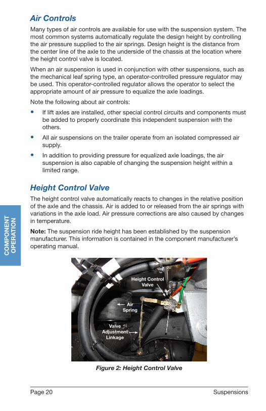
Height Control ValveThe height control valve automatically reacts to changes in the relative position of the axle and the chassis. Air is added to or released from the air springs with variations in the axle load. Air pressure corrections are also caused by changes in temperature.
Note: The suspension ride height has been established by the suspension manufacturer. This information is contained in the component manufacturer’s operating manual.
Height ControlValve
Valve Adjustment
Linkage
Air Spring
Figure 2: Height Control Valve

Page 21
CO
MP
ON
EN
TO
PE
RA
TIO
N
Disc Wheels
Disc Wheels
CAUTION! Make sure all wheel lug nuts are properly torqued to values ranging between 400 ft-lb and 500 ft-lb. These nuts should be checked often. Whenever tires are changed, the nuts and studs should be inspected to ensure they are in good condition. If nuts require frequent tightening, if studs break frequently, or if wheel nut seats round out, the assembly and mounting practices should be reviewed in order to eliminate any inappropriate procedure.
!
WARNING!• DO NOT use two-piece cone lock nuts to mount wheels
machined for use with ball seat cap nuts. Wheels that are machined to accept ball seat cap nuts will not have enough surface area to properly support a cone lock nut. Loss of torque, broken studs and cracked wheels can result from this mismatched component assembly.
• DO NOT weld aluminum wheels for any reason.• DO NOT heat aluminum wheel in an attempt to soften it for
straightening or to repair damage from impacts or other causes. Heating will weaken the aluminum alloy structure of the wheel.
!
CAUTION! Lubricants must NOT be applied to the cap nut seats or to the wheel. Lubricants must be wiped clean from the cap nut seats if applied accidentally.!
Changing Flat Tire
1. Exhaust air in the suspension air bags.
2. Set vehicle brakes and chock wheels not being serviced.
3. Place jack under the axle as close to the affected wheel as possible.
4. Jack up axle until the wheel is off of the ground then change tire.
5. Torque lug nuts in a cross pattern to 400-500 ft-lb.
WARNING!• DO NOT change tires or wheels with air pressure in the
suspension air bags. This can lead to instability, severe injury or death.
!

Page 22 NHTSA Information
NHTSA InforMatIon
If you believe that your vehicle has a defect which could cause a crash or could cause injury or death, you should immediately inform the National Highway Traffic Safety Administration (NHTSA), in addition to notifying East Manufacturing Corporation.
If NHTSA receives similar complaints, it may open an investigation, and if it finds that a safety defect exists in a group of vehicles, it may order a recall and remedy campaign. However, NHTSA cannot become involved in individual problems between you, your dealer or East Manufacturing Corporation.
To contact NHTSA, you may either call the Vehicle Safety Hotline toll-free at 888-327-4236 or 800-424-9153, or write to:
NHTSA U.S. Department of Transportation 1200 New Jersey Ave. SE Washington, D.C. 20590
You can also obtain other information about motor vehicle safety from nhtsa.gov and the Vehicle Safety Hotline.
NH
TS
AIN
FOR
MA
TIO
N
Page 23Warranty
east refuse LIMIted Warranty
East Manufacturing Corporation warrants each new refuse trailer manufactured (hereinafter referred to as the equipment) by us to be free from defects in materials and workmanship, provided that the equipment warranted hereunder is operated by the purchaser in accordance with generally approved practices, with loads not exceeding the manufacturer’s rated capacity and with loads that are not abrasive or corrosive in nature.
Refuse frame structure of the equipment found to be defective within the warranty period shall be repaired or replaced (at East’s sole option), at East’s factory location or authorized service facility. The purchaser must notify East or an authorized distributor as soon as any defect becomes apparent. The period of the warranty is for two years from the date of delivery of the equipment, and East shall bear that portion of the cost of repairing or replacing defective parts of the equipment on the following basis:
2 years ............ 100%
Any parts not manufactured by East will carry their own warranties and are carried out according to their own individual component warranties; examples include axles, suspensions, hoist, tarp, landing gear, wheels, rims, hubs, air lines, springs, airbags, valves, bearings, brakes, etc.
Tires are not warranted by East.
Suspension alignments are covered for the first 30 days only.
Paint is covered for 1 year from date of delivery on workmanship and materials. Surface corrosion caused from stone chips, road debris, scratches or impacts are not included in the warranty coverage.
This Warranty does not expand, enlarge upon, or alter in any way, the warranties provided by the manufacturers and suppliers of component parts and accessories.
The purchaser agrees to return the defective equipment or parts to East’s factory location or authorized service facility, freight prepaid, within fifteen days after the defective condition is discovered.
This warranty also excludes the following: normal wear, tear, and deterioration of the equipment; maintenance items including, but not limited
to, light bulbs, paint, brake lining, oil seals and bearings; used equipment sold “as is”; equipment that has been repaired, replaced or altered by someone other than East or one of its authorized service facilities.
EAST AND THE PURCHASER AGREE THAT IN CONSIDERATION OF THE ABOVE EXPRESSED WARRANTY, ALL OTHER WARRANTIES OTHER THAN TITLE, EITHER EXPRESSED OR IMPLIED, WHETHER ARISING UNDER LAW OR EQUALITY INCLUDING WARRANTIES OF MERCHANTABILITY AND FITNESS FOR A PARTICULAR PURPOSE ARE EXCLUDED FROM THIS CONTRACT, FURTHER, THE FOREGOING WARRANTY IS MADE SOLELY TO THE FIRST PURCHASER FROM EAST OR FROM AN AUTHORIZED DISTRIBUTOR.
The sole liability of East and the exclusive remedy of the purchaser arising out of the manufacture, sale or use of the equipment provided hereunder, on warranties or otherwise, shall be limited to the cost of repair or replacement of defective parts as herein specified. Further, East’s maximum liability hereunder arising from any cause whatsoever, including but not limited to, breach of contract or tort (including negligence), shall not exceed the contract price of the equipment furnished hereunder. East shall not be responsible for work done, equipment or parts furnished, or parts or repairs made by others unless the work is specifically ordered by East. In no event shall East be liable for removing defective parts or for reinstalling said parts when repaired or replaced by anyone other than East or an authorized service facility or for any costs incurred with such removal or reinstallation.
CONSEQUENTIAL DAMAGES - NOTWITHSTANDING ANY OTHER PROVISION OF THIS AGREEMENT, IN NO EVENT SHALL EAST BE LIABLE, WHETHER ARISING UNDER CONTRACT, TORT (INCLUDING NEGLIGENCE) OR OTHERWISE, FOR LOSS OF ANTICIPATED PROFITS, DAMAGE TO LOADS OR CONTENTS OF THE EQUIPMENT, TRANSPORTATION EXPENSES DUE TO REPAIRS, NON-OPERATION OR INCREASED EXPENSE OF OPERATION COST OF PURCHASED OR REPLACEMENT EQUIPMENT, CLAIM OF CUSTOMERS, COST OF MONEY, LOSS OF USE OF CAPITAL OR REVENUE, OR FOR ANY SPECIAL INCIDENTAL OR CONSEQUENTIAL LOSS OR DAMAGE OF ANY NATURE ARISING AT ANY TIME OR FROM ANY CAUSE WHATSOEVER.
WA
RR
AN
TY

East Manufacturing Corporation1871 State Route 44
P.O. Box 277Randolph, OH 44265
EastMfg.com
(330) 325-9921
Sales (888) 405-3278
Parts (800) 362-0851
Warranty (330) 325-9921
Service (330) 325-9921
Fax (330) 325-7851