refrigerator service manual - encompass read the safety precautions in this manual. model :...
TRANSCRIPT
CAUTIONBEFORE SERVICING THE UNIT,READ THE SAFETY PRECAUTIONS IN THIS MANUAL.
MODEL : LFX28977ST /01LFX28977WB /01LFX28977SW /01
REFRIGERATOR SERVICE MANUAL

ENC(Engineering Change Number)
- 2 -
Cover Assembly, Lamp
Duct Assembly, Multi
LED Assembly
LED Assembly
Guide, Fan
Tray, Drip
503F
120A
409E
405J
319C
319A
Loc No. SPECIFICATIONS
LFX28977 /01

- 3 -
CONTENTS
SAFETY PRECAUTIONS ....................................................................................................................................................... 21. SPECIFICATIONS ............................................................................................................................................................. 32. PARTS IDENTIFICATION ................................................................................................................................................. 43. DISASSEMBLY ............................................................................................................................................................ 5-17
REMOVING AND REPLACING REFRIGERATOR DOORS ............................................................................................. 5DOOR ............................................................................................................................................................................. 6-7DOOR ALIGNMENT .......................................................................................................................................................... 7FAN AND FAN MOTOR(Evaporator) ................................................................................................................................. 7DEFROST CONTROL ASSEMBLY ................................................................................................................................... 8LAMP ................................................................................................................................................................................. 8MULTI DUCT ..................................................................................................................................................................... 9MAIN PWB ..........................................................................................................................................................................9DISPLAY PCB ....................................................................................................................................................................9ICE BUTTON ASSEMBLY ..................................................................................................................................................9FUNNEL REPLACEMENT ..................................................................................................................................................9WATER BUTTON ASSMEBLY .........................................................................................................................................10DUCT DOOR REPLACEMENT ........................................................................................................................................10ICE CORNER DOOR REPLACEMENT ............................................................................................................................10ICEMAKER ASSEMBLY ...................................................................................................................................................10SUB PWB FOR WORKING DISPENSER ........................................................................................................................11CAP DUCT MOTOR REPLACEMENT .............................................................................................................................11AUGER MOTOR COVER .................................................................................................................................................12HOW TO REMOVE A ICE BIN HOW TO REMOVE A ICE BIN.........................................................................................13HOW TO INSERT A ICE BIN ............................................................................................................................................13HOW TO REMOVE AND REINSTALL THE PULLOUT DRAWER ..............................................................................14-15WATER VALVE DISASSEMBLY METHOD .....................................................................................................................16FAN AND FAN MOTOR DISASSEMBLY METHOD .........................................................................................................16PULL OUT DRAWER .......................................................................................................................................................17
4. ADJUSTMENT ........................................................................................................................................................... 18-19COMPRESSOR ............................................................................................................................................................... 18Introduction of E-Linear Compressor ...........................................................................................................................18-20
5. CIRCUIT DIAGRAM ........................................................................................................................................................ 216. TROUBLESHOOTING ................................................................................................................................................ 22-52
Error Code Summary ....................................................................................................................................................... 22 Troubleshooting With Error .......................................................................................................................................... 23-35 Troubleshooting Else .................................................................................................................................................. 36-54
7. COMPONENT TESTING INFORMATION .................................................................................................................. 55-63 8. TRBOUBLESHOOTING ............................................................................................................................................. 64-689. OPERATION PRINCIPLE AND REPAIR METHOD OF ICEMAKER ........................................................................ 69-7110. DESCRIPTION OF FUNCTION & CIRCUIT OF MICOM ........................................................................................... 72-76 11. EXPLODED VIEW & REPLACEMENT PARTS LIST
SAFETY PRECAUTIONS
Please read the following instructions before servicing yourrefrigerator.1. Unplug the power before handling any elctrical
componets.2. Check the rated current, voltage, and capacity.3. Take caution not to get water near any electrical
components.4. Use exact replacement parts.5. Remove any objects from the top prior to tilting the
product.

- 4 -
1. SPECIFICATIONS
DOOR DESIGN
DIMENSIONS (inches)
NET WEIGHT (pounds)
COOLING SYSTEM
TEMPERATURE CONTROL
DEFROSTING SYSTEM
DOOR FINISH
HANDLE TYPE
INNER CASE
INSULATION
ITEMS
Side Rounded
35 3/4 X 35 3/8 X 69 3/4 (WXDXH) 28cu.ft.
324(28cu.ft.)
Fan Cooling
Micom Control
Full Automatic
Heater Defrost
Embossed Metal, VCM, Stainless
Bar
ABS Resin
Polyurethane Foam
SPECIFICATIONS
VEGETABLE TRAY
COMPRESSOR
EVAPORATOR
CONDENSER
REFRIGERANT
LUBRICATING OIL
DEFROSTING DEVICE
ITEMS
Clear Drawer Type
Linear
Fin Tube Type
Wire Condenser
R-134a (140 g)
ISO10 (280 ml)
SHEATH HEATER
LED Module(24)
LED Module(12)
SPECIFICATIONS
LAMPREFRIGERATOR
FREEZER
DIMENSIONS
Depth w/ Handles
Depth w/ Handles
Depth w/ o Door
Depth (Total with Door Open)
Height to Top of Case
Height to Top of Door Hinge
Width
Width (door open 90 deg. w/o handle)
Width (door open 90 deg. w/ handle)
A
B
C
D
E
F
G
H
I
35 3/8 in
32 7/8 in
29 in
47 5/8 in
68 3/8 in
69 3/4 in
35 3/4 in
39 1/4 in
44 1/4 in
Description LFX28977** /01
28 cu.ft.

- 5 -
2. PARTS IDENTIFICATION
ADJUSTABLE REFRIGERATOR SHELVING1
The refrigerator compartment shelves are adjustable toallow flexibility for storage needs.
GALLON STORAGE BINS2
Three interchangeable bins can be arranged to suit yourstorage needs.
REMOVABLE ICE STORAGE BIN3
The ice storage bin can be removed to fill ice buckets,coolers, or pitchers.
LED INTERIOR LAMPS4
Two separate LED arrays light the freezer andrefrigerator interiors.
SHORT N’TALL BIN5
FIXED DOOR BIN6
- 6 -
3. DISASSEMBLY
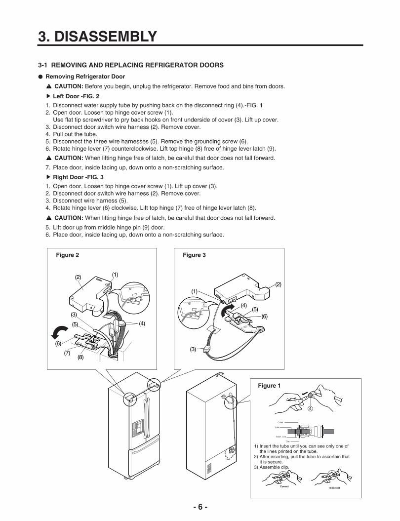
3-1 REMOVING AND REPLACING REFRIGERATOR DOORS
Removing Refrigerator Door
CAUTION: Before you begin, unplug the refrigerator. Remove food and bins from doors.
Left Door -FIG. 2
1. Disconnect water supply tube by pushing back on the disconnect ring (4).-FIG. 12. Open door. Loosen top hinge cover screw (1).
Use flat tip screwdriver to pry back hooks on front underside of cover (3). Lift up cover.3. Disconnect door switch wire harness (2). Remove cover.4. Pull out the tube.5. Disconnect the three wire harnesses (5). Remove the grounding screw (6).6. Rotate hinge lever (7) counterclockwise. Lift top hinge (8) free of hinge lever latch (9).
7. Place door, inside facing up, down onto a non-scratching surface.
CAUTION: When lifting hinge free of latch, be careful that door does not fall forward.
Right Door -FIG. 3
1. Open door. Loosen top hinge cover screw (1). Lift up cover (3).2. Disconnect door switch wire harness (2). Remove cover.3. Disconnect wire harness (5).4. Rotate hinge lever (6) clockwise. Lift top hinge (7) free of hinge lever latch (8).
5. Lift door up from middle hinge pin (9) door.6. Place door, inside facing up, down onto a non-scratching surface.
CAUTION: When lifting hinge free of latch, be careful that door does not fall forward.
Figure 2 Figure 3
Figure 1
1) Insert the tube until you can see only one ofthe lines printed on the tube.
2) After inserting, pull the tube to ascertain thatit is secure.
3) Assemble clip.

- 7 -
3-2 DOOR
Door Gasket Removal
1. Remove door frame coverStarting at top of cover and working down, snap coverout and away from door.
2. Remove gasket bracket clipsThere are two clips on each door. Start bracket removalnear one of the middle clips.1) Pull gasket back to expose gasket bracket clip and
door frame.2) Insert a flat tip screwdriver into seam between gasket
bracket and door frame and pry back until clips snapout.
3) Continue prying back along seam until all clips snapout.
Figure 1
HandleFrame Cover
Door Gasket Replacement
1. Insert gasket bracket clips1) Insert gasket bracket edge beneath door frame edge.2) Turn upper gasket bracket spring so that the spring
ends are in the door channel.3) Push in clip until you hear it snap securely into place.
Figure 4
Correct Incorrect
GasketBracket Clip
Spring
DoorFrame
Figure 5
Correct
Incorrect
4) Push in remaining clip until you hear it snap securelyinto place.
Note: Make sure that no part of gasket bracket edge protrudes from beneath door frame edge.
2. Insert gasket into channel1) Snap gasket assembly into the door bracket.<Inserting the Gasket Assembly into the Bracket Door>
Figure 2
GasketBracket Clip
GasketBracket
DoorFrame
Flat TipScrewdriver
3. Remove gasketPull gasket free from gasket channel on the threeremaining sides of door.
Figure 3

- 8 -
2) Press gasket into channels on the three remainingsides of door.
Figure 6
3. Replace door frame coverStarting at top of cover and working down, snap coverback into door.
Figure 7
Figure 8
3-3 Door Alignment
If the space between your doors is uneven, follow theinstructions below to align the doors:Remove the Base Grillie. Turn the leveling legs (CCW) toraise or (CW) to lower the height of the front of therefrigerator by using flat blade screw driver or 11/32"wrench. Use the wrench (Included with the User Manual) toadjust the bolt in the door hinge to adjust the height. (CCWto raise or CW to lower the height.)
3-4 FAN AND FAN MOTOR(EVAPORATOR)
1. Remove the freezer drawer. (If your refrigerator has anicemaker, remove the icemaker first)
2. Remove the plastic guide for slides on left side byunscrewing phillips head screws.
3. Remove the grille by removing four screws and pullingthe grille forward.
4. Remove the Fan Motor assembly by loosening 3 screwsand disassembling the shroud.
5. Pull out the fan and separate the Fan Motor and Bracket.
Figure 9
FAN MOTOR
BRACKETMOTOR
Shroud
- 9 -
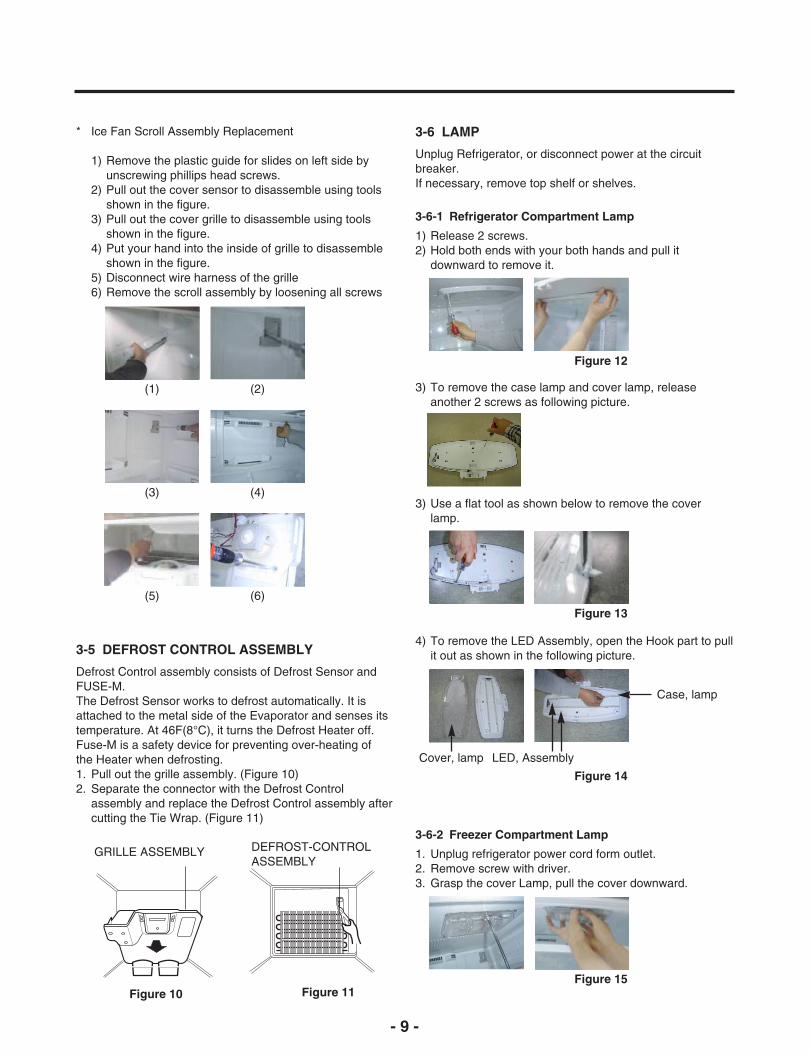
* Ice Fan Scroll Assembly Replacement
1) Remove the plastic guide for slides on left side byunscrewing phillips head screws.
2) Pull out the cover sensor to disassemble using toolsshown in the figure.
3) Pull out the cover grille to disassemble using tools shown in the figure.
4) Put your hand into the inside of grille to disassemble shown in the figure.
5) Disconnect wire harness of the grille 6) Remove the scroll assembly by loosening all screws
(1) (2)
(3) (4)
(5) (6)
Figure 12
3-5 DEFROST CONTROL ASSEMBLY
Defrost Control assembly consists of Defrost Sensor andFUSE-M.The Defrost Sensor works to defrost automatically. It isattached to the metal side of the Evaporator and senses itstemperature. At 46F(8°C), it turns the Defrost Heater off.Fuse-M is a safety device for preventing over-heating ofthe Heater when defrosting.1. Pull out the grille assembly. (Figure 10)2. Separate the connector with the Defrost Control
assembly and replace the Defrost Control assembly aftercutting the Tie Wrap. (Figure 11)
Figure 10 Figure 11
GRILLE ASSEMBLY DEFROST-CONTROLASSEMBLY
3-6 LAMP
Unplug Refrigerator, or disconnect power at the circuitbreaker.If necessary, remove top shelf or shelves.
1) Release 2 screws.2) Hold both ends with your both hands and pull it
downward to remove it.
3-6-1 Refrigerator Compartment Lamp
Figure 13
3) Use a flat tool as shown below to remove the coverlamp.
Figure 14
4) To remove the LED Assembly, open the Hook part to pullit out as shown in the following picture.
Cover, lamp
Case, lamp
LED, Assembly
3) To remove the case lamp and cover lamp, releaseanother 2 screws as following picture.
Figure 15
1. Unplug refrigerator power cord form outlet.2. Remove screw with driver.3. Grasp the cover Lamp, pull the cover downward.
3-6-2 Freezer Compartment Lamp

- 10 -
3-7 MULTI DUCT
1. Remove the upper andlower Caps by using aflat screwdriver, andremove 2 screws.(Figure 16)
2. Disconnect the lead wireon the bottom position.
3-8 MAIN PWB
1) Loosen the 3 screws on the PWB cover.
Figure 16
3-9 DISPENSER
1) Pull out the darin 2) Hold the inner side ofcover dispenser withboth hands at the handleside to pull it out forward.
2) Remove the PWB cover
3) Disconnect wire harness and replace the main PWB inthe reverse order of removal.
3-10 DISPLAY PCB
As shown below, remove 1 case PCB fixing screw.Remove the display PCB fixing screw.
3-11 ICE BUTTON ASSEMBLY
1) Remove the screw fixing the button lever.2) Push the spring from the hanging hook to remove it.3) Apply some pressure to the rib in direction and lift the
button in direction.
3-12 FUNNEL REPLACEMENT
Pull down and forward.
3) If nozzle is interfered with button,push and pull out the bottom ofbutton.
4) Rmove theconnected partof Lead wire.
CAUTION: When replacing the dispensor cover in thereverse order of removal, be careful that the lead wiredoes not come out and the water tube is not pinched bythe dispensor.
Case, PCB
Button Lever
Display PCB

- 11 -- 11 -
3-14 DUCT DOOR REPLACEMENT
1) Pull up and out on the dispenser cover to remove.2) Disconnect the wire harness.3) Remove the funnel4) Replace in reverse order.
3-15 ICE CORNER DOOR REPLACEMENT
1) Loosen the front screw as shown in the picture.2) Lift up the hinge with one hand.3) Pull out the Ice Corner Door with the other hand.
3-13 WATER BUTTON ASSMEBLY
1) Romove screws.2) Grasp the Button assembly and lift up.
3-16 ICEMAKER ASSEMBLY
1) Loosen two screws as shown in the first picture.
2) Disconnect the wire harness & ground screw replacetheIcemaker assembly in the reverse order of removal.
3) It separates a ground connection screw.
Button Lever
hinge

- 12 -- 11 -
3-17 SUB PWB FOR WORKING DISPENSER
1) Loosen the screw on the sub PWB.
2) Pull the sub PWB down.3) Disconnect the wire harness and replace the sub PWB in
the reverse order of removal.
3-18 CAP DUCT MOTOR REPLACEMENT
1) Separate the Housing of the Cap Duct Motor.
2) Unscrew 3 screws to disassemble the motor.
3) When replacing to a new Motor, always hold the DuctDoor with your hand to install the Motor.
4) Assemble on the screws.
5) Contract the Housing.
Cap Duct Motor
Duct Door
- 13 -
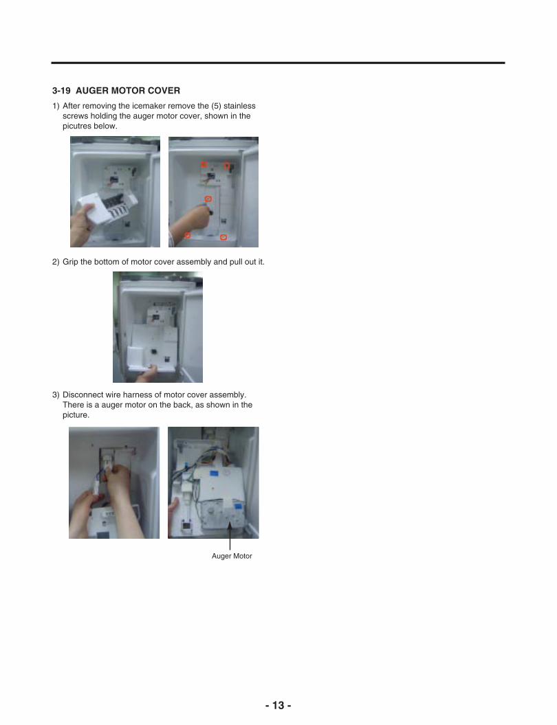
3-19 AUGER MOTOR COVER
1) After removing the icemaker remove the (5) stainlessscrews holding the auger motor cover, shown in thepicutres below.
2) Grip the bottom of motor cover assembly and pull out it.
3) Disconnect wire harness of motor cover assembly.There is a auger motor on the back, as shown in thepicture.
Auger Motor

- 14 -
3-20 HOW TO REMOVE A ICE BIN
1) Grip the handles, as shown in the picture.
2) Lift the lower part slightly.
3-21 HOW TO INSERT A ICE BIN
1) Insert the Ice Bin, slightly tilting it to avoid touching theIcemaker. (especially, icemaker lever)
※ Insert the ice bin carefully avoid contacting the automaticshut off arm.
3) Take the Ice Bin out slowly.

- 15 -
3-22 HOW TO REMOVE AND REINSTALL THE PULLOUT DRAWER
3-22-1 Follow Steps to Remove
Step 1) Open the freezer door. Step 2) Remove the lower basket.
Step 3) Remove the two screws from the guide rails (one from each side).
Step 4) Lift the freezer door up to unhook it from the railsupport and remove.Pull both rails to full extension.
Step 5) First: Remove the gear from the left side first by releasing the tab behind the gear, place a screwdriver between the gear and the tab and pull up on the gear.
Second: Remove the center rail.
Third: Remove the gear from the right side by following the same steps for the left side.
NOTE: THIS TAB MUST BE PUSHED IN TO RELEASE THE GEAR.

- 16 -
3-22-2 Follow Steps to Reinstall
Step 1) Reinstall the right side gear into the clip.
Step 2) Insert the rail into the right side gear. Gears do notneed to be perpendicular to each other.
Step 3) Insert the rail into the left side gear, and insert thegear into the clip.
Step 4) The rail system will align itself by pushing the railsall the way into the freezer section.Pull the rails back out to full extension.
Step 5) Reinstall the freezer door by inserting the rail tabsinto the guide rail.
Step 6) Reinstall the two screws into the guide rails(one from each side).
Step 7) Reinstall the lower basket, and close the freezerdoor.

- 17 -
3-23. WATER VALVE DISASSEMBLY METHOD
1) Turn off the water. Then separate the water line from thevalve.
3-24. FAN AND FAN MOTOR DISASSEMBLYMETHOD
1) Using a short screwdriver, loosen one SCREW in DRAINPIPE ASSEMBLY and one connected to the MOTORCOVER.
2) Separate the Mechanical Cover and Valve Screw.
3) Separate the housing and pull out the valve.
4) Lay a dry towel on the floor and get ready to spill waterfrom the water filter. Pull out the Cilp. Then press tecollet to separate the tube from the connector and pourout the water until emptied.
Mechanical Cover
Housing
MOTOR COVER
2) Pull and separate the FAN ASSEMBLY and MOTORturning counterclockwise based on the MOTOR SHAFT.
FAN ASSEMBLY MOTOR
The assembly is in the reverse order of the disassemblyand take special care for the following details.1. Be careful not to bend the tube during assembly.2. Press the WATER DISPENSER button until water pours
out and check for leakage in the CONNECTOR TUBE (Itdiffers by the water pressure but usually takes about 2minutes until water pours out.)

- 18 -
3-25 PULL OUT DRAWER
To separate the drawer, push the front left and right hooksin ① direction to pull up and remove.Then gently lift the gear part of rear left and right side of thedrawer and pull it out in ③ direction.
To install, reposition the gear part of rear left and right sideof the drawer after pulling out both rails as much aspossible, and gently push down both left and right sidewhile checking the hook on the front part.
- 19 -
4-1-3 Note for usage
(1) Be careful not to allow over-voltage and over-current.(2) If compressor is dropped or handled carelessly, poor
operation and noise may result.(3) Use proper electric components appropriate to the
Particular Compressor in your product.(4) Keep Compressor dry.
If the Compressor gets wet (in the rain or a dampenvironment) and rust forms in the pin of the HermeticTerminal, poor operation and contact may result.
(5) When replacing the Compressor, be careful that dust,humidity, and soldering flux don’t contaminate the insideof the compressor. Dust, humidity, and solder fluxcontaminate the cylinder and may cause noise,improper operation or even cause it to lock up.
4-2-4 Motor Restarting and PTC Cooling
(1) It requires approximately 5 minutes for the pressure toequalize before the compressor can restart.
(2) The PTC device generates heat during operation.Therefore, it must be allowed to cool before thecompressor can restart.
4-2-5 Relation of PTC-Starter and OLP
(1) If the compressor attempts to restart before the PTCdevice is cooled, the PTC device will allow current toflow only to the main winding.
(2) The OLP will open because of the over currentcondition. This same process will continue (3 to 5 times)when the compressor attempts to restart until the PTCdevice has cooled. The correct OLP must be properlyattached to prevent damage to the compressor.Parts may appear physically identical but could havedifferent electrical ratings. Replace parts by part numberand model number. Use only approved substitute parts.
4-2-6 Note for Using the PTC-Starter
(1) Be careful not to allow over-voltage and over-current.(2) Do not drop or handle carelessly.(3) Keep away from any liquid.
If liquid such as oil or water enters the PTC, PTCmaterials may fail due to breakdown of their insulatingcapabilities.
(4) If the exterior of the PTC is damaged, the resistancevalue may be altered. This can cause damage to thecompressor and result in a no-start or hard-to-startcondition.
(5) Always use the PTC designed for the compressor andmake sure it is properly attached to the compressor.Parts may appear physically identical but could havedifferent electrical ratings. Replace parts by part numberand model number. Use only approved substitute parts.
4. ADJUSTMENT
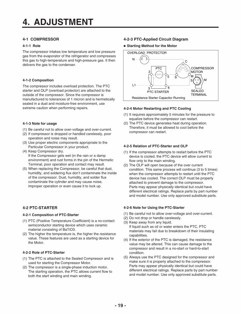
4-2-3 PTC-Applied Circuit Diagram
4-1-1 Role Starting Method for the Motor
4-1 COMPRESSOR
4-2 PTC-STARTER
The compressor intakes low temperature and low pressuregas from the evaporator of the refrigerator and compressesthis gas to high-temperature and high-pressure gas. It thendelivers the gas to the condenser.
4-1-2 Composition
The compressor includes overload protection. The PTCstarter and OLP (overload protector) are attached to theoutside of the compressor. Since the compressor ismanufactured to tolerances of 1 micron and is hermeticallysealed in a dust and moisture-free environment, useextreme caution when performing repairs.
4-2-1 Composition of PTC-Starter
(1) PTC (Positive Temperature Coefficient) is a no-contactsemiconductor starting device which uses ceramicmaterial consisting of BaTiO3.
(2) The higher the temperature is, the higher the resistancevalue. These features are used as a starting device forthe Motor.
4-2-2 Role of PTC-Starter
(1) The PTC is attached to the Sealed Compressor and isused for starting the Compressor Motor.
(2) The compressor is a single-phase induction motor.The starting operation, the PTC allows current flow toboth the start winding and main winding.
PTC STARTER SEALEDTERMINAL
COMPRESSORMOTOR
C
MS M
3 6
5 S
N
L1
OVERLOAD PROTECTOR
Resistance Starter Capacitor Running
PTC22

- 20 -
4-4 TO REMOVE THE COVER PTC
(1) Remove the Cover Back M/C.(2) Disconnect two housing upper side of comp connected
in.(3) Loosen two screws on comp base.
4-3 OLP (OVERLOAD PROTECTOR)
4-3-1 Definition of OLP
4-3-2 Role of the OLP
(1) The OLP is attached to the Sealed Compressor used forthe Refrigerator. It prevents the Motor Coil from beingstarted in the Compressor.
(2) For normal operation of the OLP, do not turn the AdjustScrew of the OLP in any way.
(1) OLP (OVERLOAD PROTECTOR) is attached to theCompressor and protects the Motor by opening thecircuit to the Motor if the temperature rises andactivating the bimetal spring in the OLP.
(2) When high current flows to the Compressor motor, theBimetal works by heating the heater inside the OLP, andthe OLP protects the Motor by cutting off the currentflowing to the Compressor Motor.
PartCustomer partnumber
Lot code/date code330 FBYY -S1 BOX98
12345678
Physicalterminationpart number
Electricalcharacteristics
part number
No. NameBase, phenolic(UL 94 V-0 rated)Movable arm support, plated steelStationary contact support,plated steelHeater support, plated steelHeater, resistance alloyDisc, thermostatic alloyMovable arm, spring temper copper alloyContact, movable, silver on copperContact, stationary, silver on copperSlug, plated steelCover, polyester(UL 94 V -0 rated)Pin connector, plated copper alloy(To engage 2.33/2.66 mm dia. pin)Quick-connect terminal, brass,conforms to UL 310, MEMA DC-2, DIN 46344
(OVERLOAD PROTECTOR cross section)
Figure 19
(1) Remove the Cover Back M/C.(2) Disconnect two housing upper side of comp connected
in.(3) Loosen two screws on comp base.
- 21 -
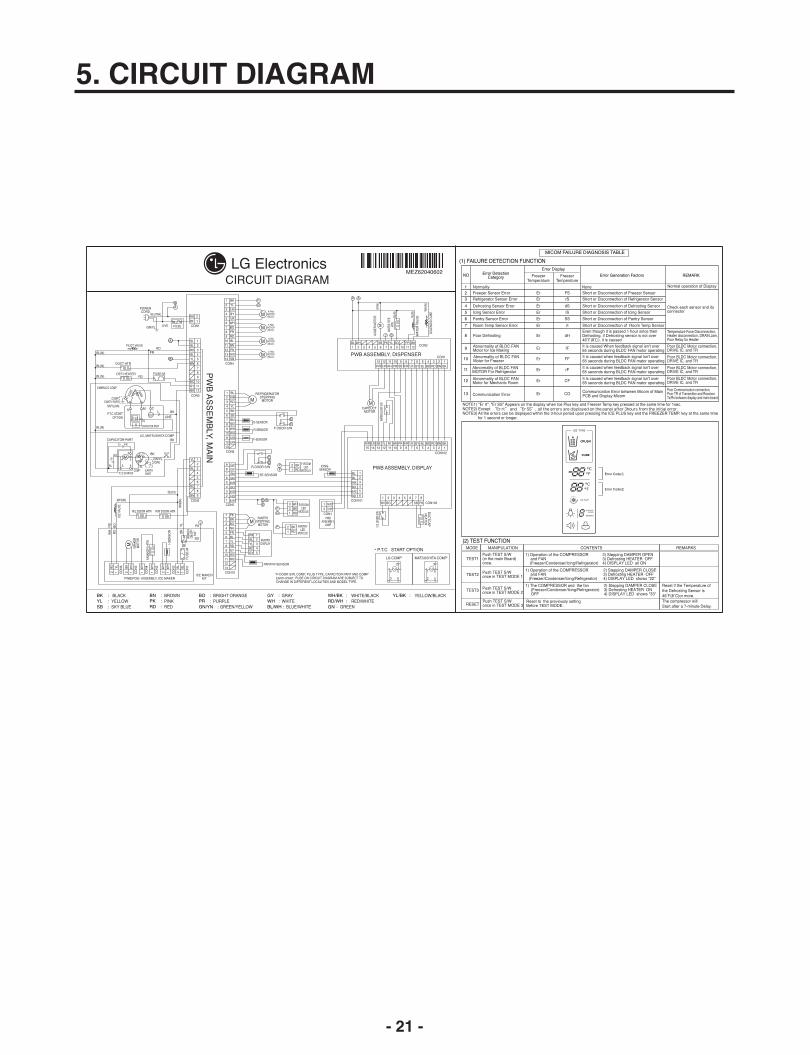
5. CIRCUIT DIAGRAM
- 22 -
6. TROUBLESHOOTING
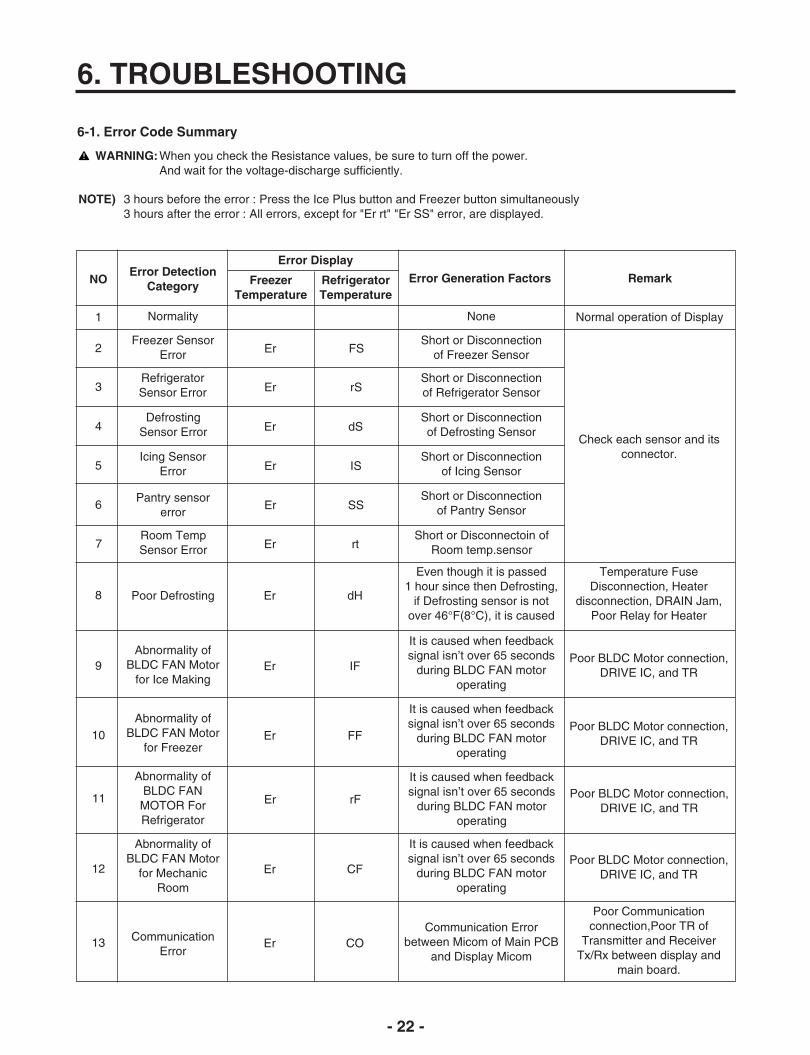
6-1. Error Code Summary
NOError Detection
Category
1 Normality None Normal operation of Display
2Freezer Sensor
Error Er FSShort or Disconnection
of Freezer Sensor
3RefrigeratorSensor Error Er rS
Short or Disconnectionof Refrigerator Sensor
Check each sensor and itsconnector.
Error Generation Factors Remark
WARNING:When you check the Resistance values, be sure to turn off the power.And wait for the voltage-discharge sufficiently.
Error Display
FreezerTemperature
RefrigeratorTemperature
4Defrosting
Sensor Error Er dSShort or Disconnectionof Defrosting Sensor
5Icing Sensor
Error Er ISShort or Disconnection
of Icing Sensor
6Pantry sensor
error Er SS
Short or Disconnectionof Pantry Sensor
8 Poor Defrosting Er dH
Even though it is passed 1 hour since then Defrosting,
if Defrosting sensor is notover 46°F(8°C), it is caused
Temperature FuseDisconnection, Heater
disconnection, DRAIN Jam,Poor Relay for Heater
9Abnormality of
BLDC FAN Motorfor Ice Making
Er IF
It is caused when feedbacksignal isn’t over 65 seconds
during BLDC FAN motoroperating
Poor BLDC Motor connection,DRIVE IC, and TR
10Abnormality of
BLDC FAN Motorfor Freezer
Er FF
It is caused when feedbacksignal isn’t over 65 seconds
during BLDC FAN motoroperating
Poor BLDC Motor connection,DRIVE IC, and TR
12
Abnormality ofBLDC FAN Motor
for MechanicRoom
Er CF
It is caused when feedbacksignal isn’t over 65 seconds
during BLDC FAN motoroperating
Poor BLDC Motor connection,DRIVE IC, and TR
13 CommunicationError
Er COCommunication Error
between Micom of Main PCBand Display Micom
Poor Communicationconnection,Poor TR of
Transmitter and ReceiverTx/Rx between display and
main board.
NOTE) 3 hours before the error : Press the Ice Plus button and Freezer button simultaneously3 hours after the error : All errors, except for "Er rt" "Er SS" error, are displayed.
7Room TempSensor Error Er rt
Short or Disconnectoin ofRoom temp.sensor
11
Abnormality ofBLDC FANMOTOR ForRefrigerator
Er rF
It is caused when feedbacksignal isn’t over 65 seconds
during BLDC FAN motoroperating
Poor BLDC Motor connection,DRIVE IC, and TR
- 23 -
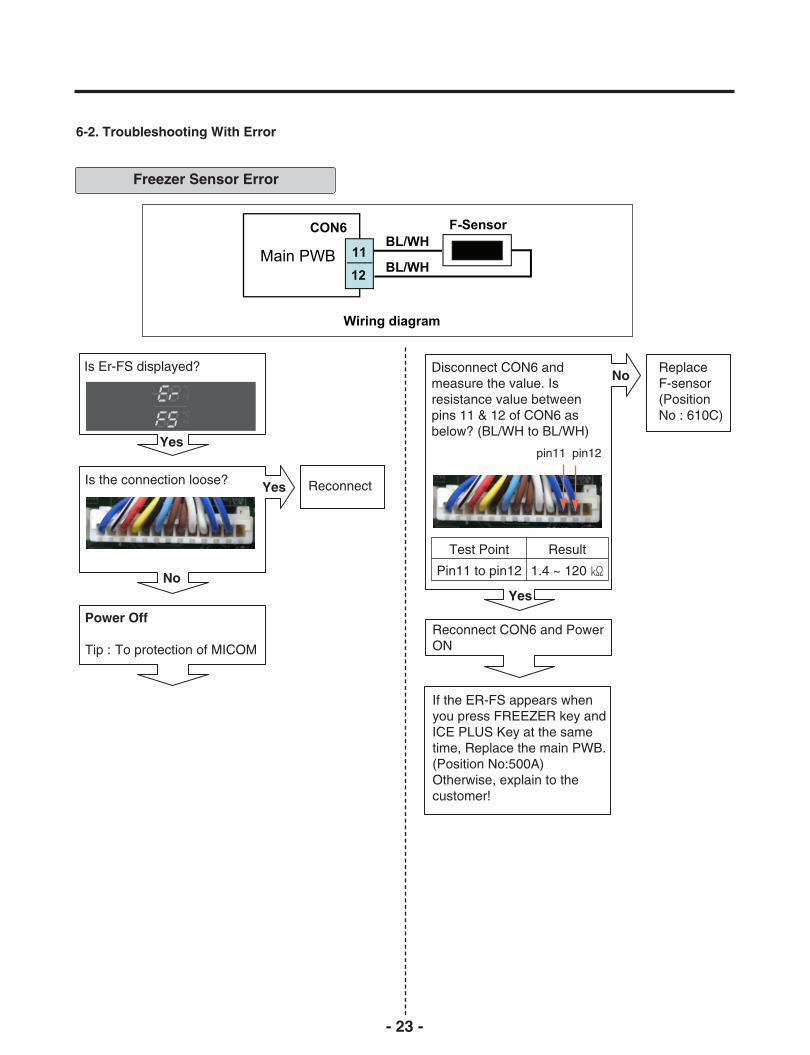
6-2. Troubleshooting With Error
Freezer Sensor Error
Is Er-FS displayed?
Is the connection loose?
Power Off
Tip : To protection of MICOM
Reconnect
Reconnect CON6 and PowerON
If the ER-FS appears whenyou press FREEZER key andICE PLUS Key at the sametime, Replace the main PWB.(Position No:500A)Otherwise, explain to thecustomer!
Disconnect CON6 andmeasure the value. Isresistance value betweenpins 11 & 12 of CON6 asbelow? (BL/WH to BL/WH)
ReplaceF-sensor(PositionNo : 610C)
No
Yes
No
Yes
Yes
Test Point
Pin11 to pin12
Result
1.4 ~ 120
pin11 pin12
- 24 -
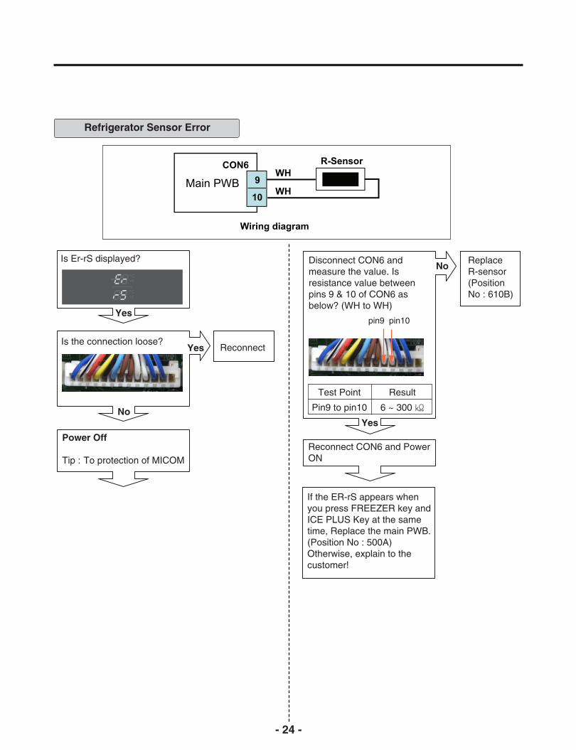
Refrigerator Sensor Error
Is Er-rS displayed?
Is the connection loose?
Power Off
Tip : To protection of MICOM
Reconnect
Reconnect CON6 and PowerON
If the ER-rS appears whenyou press FREEZER key andICE PLUS Key at the sametime, Replace the main PWB.(Position No : 500A)Otherwise, explain to thecustomer!
Disconnect CON6 andmeasure the value. Isresistance value betweenpins 9 & 10 of CON6 asbelow? (WH to WH)
ReplaceR-sensor(PositionNo : 610B)
No
Yes
No
Yes
Yes
Test Point
Pin9 to pin10
Result
6 ~ 300
pin9 pin10

- 25 -
Defrost Sensor Error
Is Er-dS displayed?
Is the connection loose?
Power Off
Tip : To protection of MICOM
Reconnect
Reconnect and Power ON
Checking Open or Short of wire
If the ER-dS appears whenyou press FREEZER key andICE PLUS Key at the sametime, Replace the mainPWB.(Position No : 500A)Otherwise, explain to thecustomer!
Is resistance value betweenpins 1 & 2 of Housing- A asbelow? (BO to BO)
ReplaceD-sensor(PositionNo :400A)
No
Yes
No
Yes
Yes
Test Point
Pin1 To pin2
Result
6 ~ 300
pin1pin2
Disconnect CON6 andmeasure the value. Isresistance value betweenpins 7 & 8 of CON6 asbelow? (BN to BN)
ReplaceD-sensor(PositionNo : 400A)
No
Yes
Test Point
Pin7 to pin8
Result
6 ~ 300
pin7 pin8

- 26 -
Replace theIcing-Sensor(PositionNo : 600B)
No
Icing Room Sensor Error
Is the connection loose?
Display PWB Inner of Icing door
Reconnect
Reconnect and Power ON
Checking Open or Short of wire
If the ER-IS appears whenyou press FREEZER key andICE PLUS Key at the sametime, Replace Display PWB.(Position No : 501A)Otherwise, explain to thecustomer!
Is resistance value betweenpins 1 & 2 of Housing- A asbelow? (BL to BL)
Is Er-IS displayed?
Yes
No
Yes
Yes
Test Point
(1) To (2)
Result
1.4 ~ 120
Icing room Sensor Resistance
Test Point
pin1 To pin2
Result
1.4 ~ 120
Disconnect CON101 andmeasure the value. Isresistance value betweenpins 1 & 2 of CON101 asbelow? (BL to BL)
Replace theIcing-Sensor(PositionNo : 600B)
No
Yes
pin1 BL pin2 BL
pin1 BL
pin2 BL

- 27 -
Pantry Sensor Error
Is Er-SS displayed?
Is the connection loose? Reconnect
Reconnect and Power ON
Checking Open or Short of wire
If the ER-SS appears whenyou press FREEZER key andICE PLUS Key at the sametime, Replace the mainPWB.(Position No : 500A)Otherwise, explain to thecustomer!
Is resistance value betweenpins 3 & 6 of Housing- A asbelow? (BN to BN)
ReplacePantry-sensor
No
Yes
No
Yes
Yes
Test Point
Pin3 To pin6
Result
6 ~ 300
Test Point
Pin10 to pin11
Result
6 ~ 300
Disconnect CON10 andmeasure the value. Isresistance value betweenpins 10 & 11 of CON10 asbelow? (WH/RD to WH/RD)
ReplacePantry-sensor
No
Yes
Power Off
Tip : To protection of MICOM
pin3
pin6
pin10 pin11
- 28 -
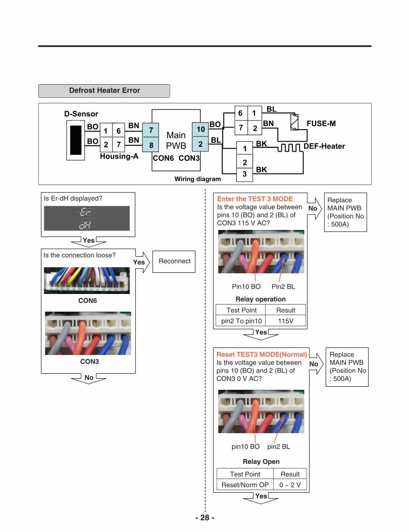
Defrost Heater Error
Is Er-dH displayed?
Is the connection loose?Reconnect
Reset TEST3 MODE(Normal)Is the voltage value betweenpins 10 (BO) and 2 (BL) ofCON3 0 V AC?
Relay operation
Enter the TEST 3 MODEIs the voltage value betweenpins 10 (BO) and 2 (BL) ofCON3 115 V AC?
ReplaceMAIN PWB(Position No: 500A)
No
ReplaceMAIN PWB(Position No: 500A)
No
Yes
Yes
Yes
Yes
Test Point
pin2 To pin10
Result
115V
Relay Open
Test Point
Reset/Norm OP
Result
0 ~ 2 V
No
CON6
CON3
Pin10 BO Pin2 BL
pin10 BO pin2 BL

- 29 -
Is the resistance valuebetween pins 10 (BO) And 2 (BL) of CON3 like as below?
Is the resistance value ofDEF-sensor like as below? Itdepends on the temperature.
Explain to the customer!:It can be occurred, when the gasket is notstuck to product or when you put the hightemperature loads (hot foods) a lot in theproduct.
Heater Resistance
Is the resistance value ofheater like as below?
ReplaceHeater(PositionNo : 408A)
No
ReplaceD-sensor(PositionNo : 400A)
No
NormalYes
Is the connection loose?ReconnectYes
No
Is the resistance value ofFuse –M like as below?
ReplaceFuse-M(PositionNo : 400A)
No
No
Yes
Yes
Test Point
(1) To (2)
Result
34 ~ 42 Ω
Resistance
Test Point
(1) To (2)
Result
34 ~ 42 Ω
Open or Short of Fuse-M
Test Point
(1) To (2)
Result
0 Ω
-30
-20
-10
0
Test Point
129.3
76.96
47.34
30
Result
10
20
30
40
Test Point
19.53
13.03
8.896
6.201
Result
Defrost Sensor Resistance
Pin10 BO Pin2 BL
(1) BL (2) BN
Yes
(1) (2)
(1) BO
(2) BO
- 30 -
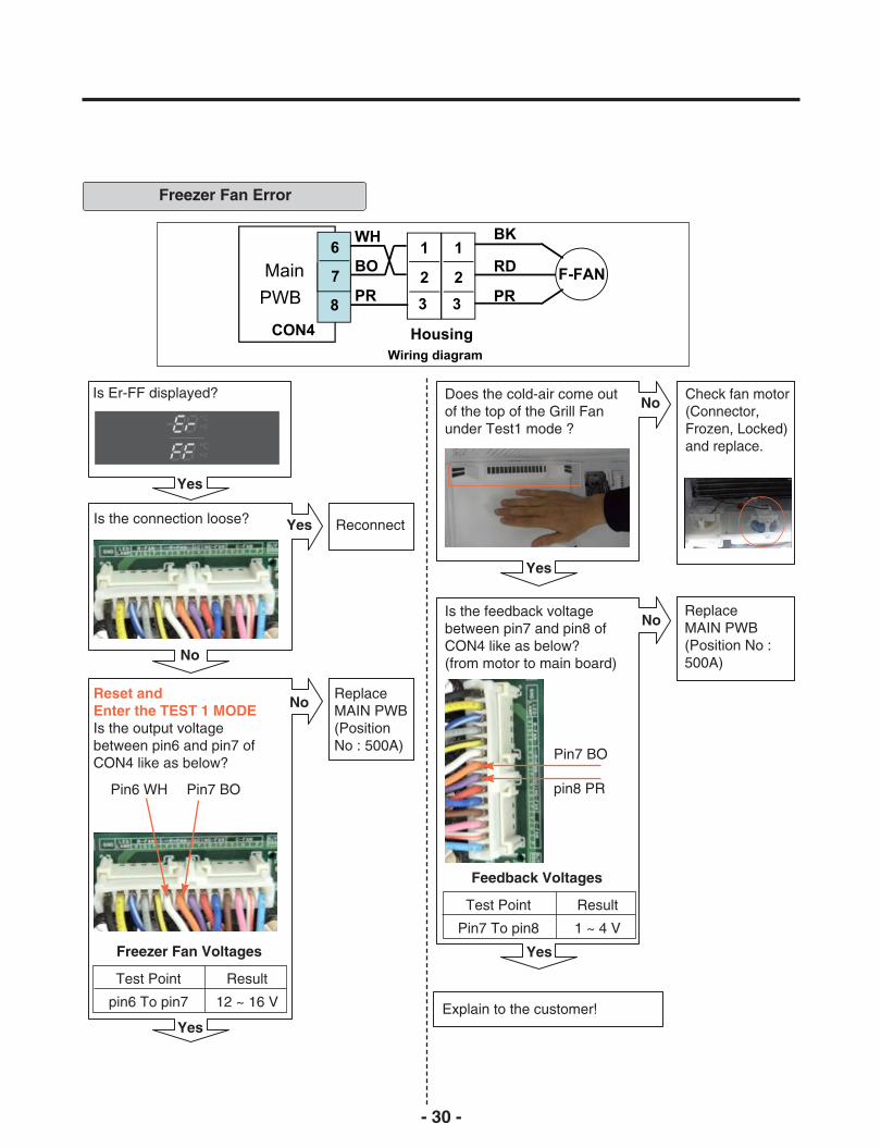
Freezer Fan Error
Is Er-FF displayed?
Is the connection loose? Reconnect
Is the feedback voltagebetween pin7 and pin8 ofCON4 like as below?(from motor to main board)
Does the cold-air come outof the top of the Grill Fanunder Test1 mode ?
Check fan motor(Connector,Frozen, Locked)and replace.
No
ReplaceMAIN PWB(Position No :500A)
No
Yes
Yes
Yes
Yes
Feedback Voltages
Test Point
Pin7 To pin8
Result
1 ~ 4 V
Freezer Fan Voltages
Test Point
pin6 To pin7
Result
12 ~ 16 V
Yes
No
Reset and Enter the TEST 1 MODEIs the output voltagebetween pin6 and pin7 ofCON4 like as below?
ReplaceMAIN PWB(PositionNo : 500A)
Explain to the customer!
No
Pin6 WH Pin7 BO
Pin7 BO
pin8 PR
- 31 -
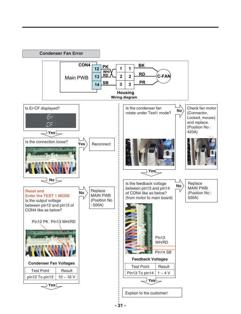
Condenser Fan Error
Is Er-CF displayed?
Is the connection loose? Reconnect
Is the feedback voltagebetween pin13 and pin14of CON4 like as below?(from motor to main board)
Is the condenser fanrotate under Test1 mode?
Check fan motor(Connector,Locked, mouse)and replace.(Position No :420A)
No
ReplaceMAIN PWB(Position No :500A)
No
Yes
Yes
Yes
Yes
Feedback Voltages
Test Point
Pin13 To pin14
Result
1 ~ 4 V
Condenser Fan Voltages
Test Point
pin12 To pin13
Result
10 ~ 16 V
Yes
No
Reset andEnter the TEST 1 MODEIs the output voltagebetween pin12 and pin13 ofCON4 like as below?
ReplaceMAIN PWB(Position No: 500A)
Explain to the customer!
No
Pin12 PK Pin13 WH/RD
Pin13WH/RD
Pin14 SB
- 32 -
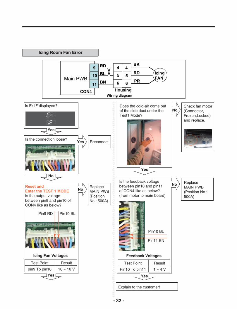
Icing Room Fan Error
Is Er-IF displayed?
Is the connection loose?Reconnect
Is the feedback voltagebetween pin10 and pin11of CON4 like as below?(from motor to main board)
Does the cold-air come outof the side duct under theTest1 Mode?
Check fan motor(Connector,Frozen,Locked)and replace.
No
ReplaceMAIN PWB(Position No :500A)
No
Yes
Yes
Yes
Yes
Feedback Voltages
Test Point
Pin10 To pin11
Result
1 ~ 4 V
Icing Fan Voltages
Test Point
pin9 To pin10
Result
10 ~ 16 V
Yes
No
Reset andEnter the TEST 1 MODEIs the output voltagebetween pin9 and pin10 ofCON4 like as below?
ReplaceMAIN PWB(PositionNo : 500A)
Explain to the customer!
No
Pin9 RD Pin10 BL
Pin10 BL
Pin11 BN
- 33 -
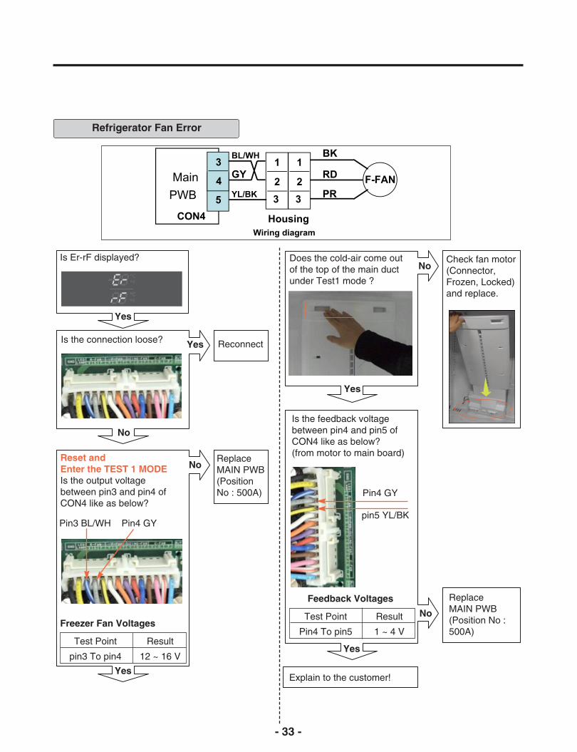
Refrigerator Fan Error
Is Er-rF displayed?
Is the connection loose? Reconnect
Is the feedback voltagebetween pin4 and pin5 ofCON4 like as below?(from motor to main board)
Does the cold-air come outof the top of the main ductunder Test1 mode ?
Check fan motor(Connector,Frozen, Locked)and replace.
No
Yes
Yes
Yes
Feedback Voltages
Test Point
Pin4 To pin5
Result
1 ~ 4 VFreezer Fan Voltages
Test Point
pin3 To pin4
Result
12 ~ 16 V
Yes
No
Reset andEnter the TEST 1 MODEIs the output voltagebetween pin3 and pin4 ofCON4 like as below?
ReplaceMAIN PWB(PositionNo : 500A)
Explain to the customer!
No
ReplaceMAIN PWB(Position No :500A)
No
Pin3 BL/WH Pin4 GY
Yes
Pin4 GY
pin5 YL/BK

- 34 -
Communication Error
Is Er-CO displayed?
Display PWBIs the connection loose?
Reconnect
Display PWBIs the voltage betweenpin4 and pin5 of CON1010 V or 5 V?
Replace theDisplay PWB(Position No :501A)
Yes
Yes
Yes
No
Yes
Transmitter Voltages
Test Point
pin4 To pin5
Result
0 V or 5 V
Receiver fail Voltages
Test Point
pin3 To pin5
Result
0 V or 5 V
No
Display PWBIs the voltage betweenpins 3 and pin 5 of CON101?
Replace theDisplay PWB(Position No: 501A)
Is the joint connection looseIn the Hinge?
Yes
ReconnectNo
Pin5 WH/RD Pin3 WH/BK
No
Pin4 BO
Pin5 WH/RD
- 35 -
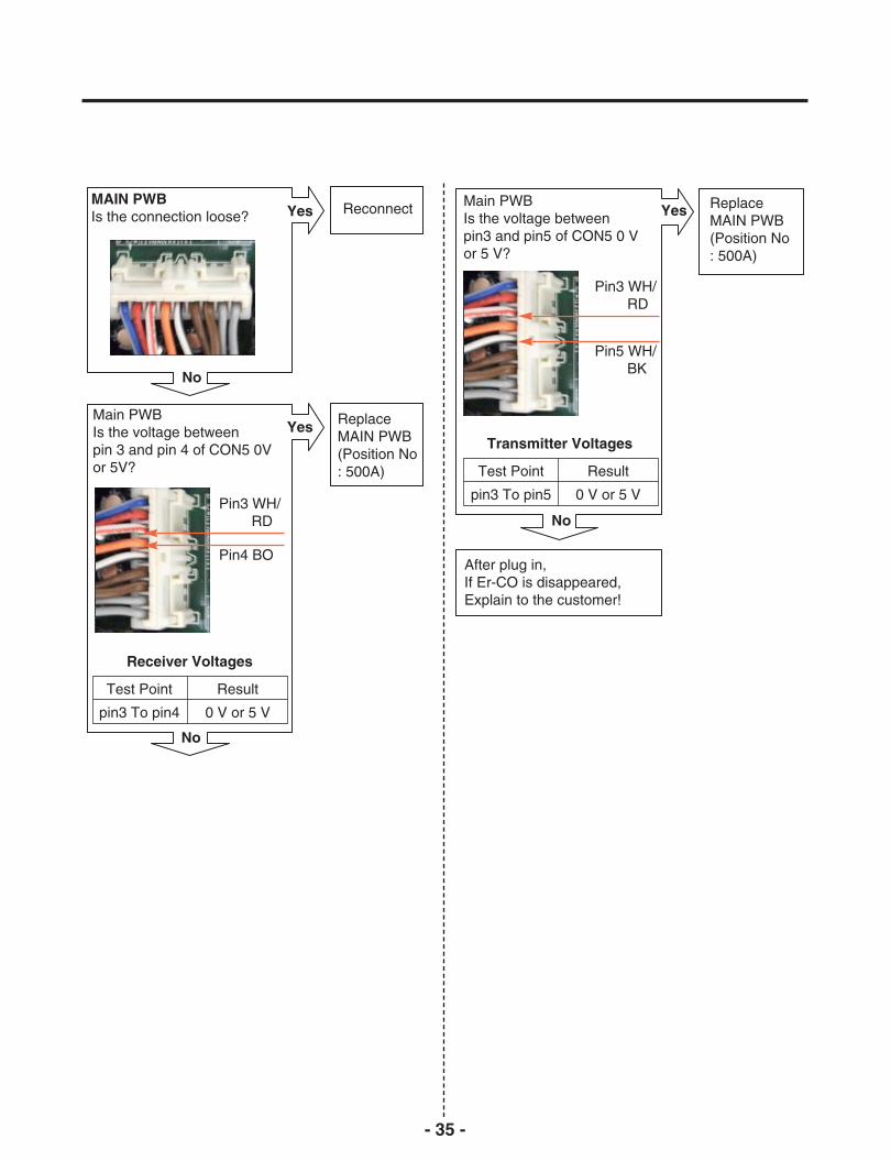
MAIN PWBIs the connection loose?
After plug in,If Er-CO is disappeared,Explain to the customer!
Transmitter Voltages
Main PWBIs the voltage betweenpin3 and pin5 of CON5 0 Vor 5 V?
ReplaceMAIN PWB(Position No: 500A)
YesReconnectYes
Main PWBIs the voltage between pin 3 and pin 4 of CON5 0Vor 5V?
ReplaceMAIN PWB(Position No: 500A)
Yes
No
No
Test Point
pin3 To pin5
Result
0 V or 5 V
Receiver Voltages
Test Point
pin3 To pin4
Result
0 V or 5 V
No
Pin3 WH/RD
Pin4 BO
Pin3 WH/RD
Pin5 WH/BK
- 36 -
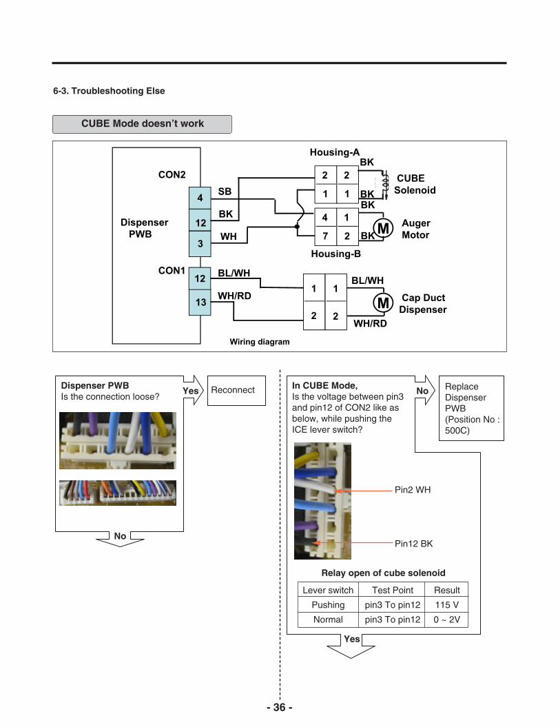
6-3. Troubleshooting Else
CUBE Mode doesn’t work
Dispenser PWBIs the connection loose?
ReconnectYes In CUBE Mode,Is the voltage between pin3and pin12 of CON2 like asbelow, while pushing theICE lever switch?
ReplaceDispenserPWB(Position No :500C)
No
No
Yes
Relay open of cube solenoid
Lever switch
Pushing
Normal
Test Point
pin3 To pin12
pin3 To pin12
Result
115 V
0 ~ 2V
Pin2 WH
Pin12 BK

- 37 -
In CUBE Mode,Is the voltage between pin3and pin4 of CON2 like asbelow, while pushing theICE lever switch?
ReplaceDispenserPWB(PositionNo : 500C)
Resistance of Auger Motor
Is the resistance valuebetween (1) and (2) of theAuger motor like as below?
ReplaceAuger Motor(Position No: 606A)
No
Yes
No
Yes
Test Point
(1) To (2)
Result
2.38 ~ 4.02Ω
(1)(2)
Resistance of Cube solenoid
Is the resistance valuebetween (1) and (2) of thecube solenoid like as below?
ReplaceCubeSolenoid(Position No: 614A)
No
Yes
Test Point
(1) To (2)
Result
32 ~ 40Ω
(1) (2)
Output voltage of auger motor
Lever switch
Pushing
Normal
Test Point
pin3 To pin4
pin3 To pin4
Result
115 V
0 ~ 2 V
In CUBE Mode, Is the voltage between pin12and pin13 of CON1 like asbelow, while pushing the ICElever switch?
ReplaceDispenserPWB(PositionNo: 500C)
Yes
No
Pin12 BL/WHPin13 WH/RD
Output voltage of dispenser cap duct
Lever switch
Pushing
Normal
Test Point
pin12 To pin13
pin12 To pin13
Result
12 V
0 V
Pin3 WH
Pin4 SB

- 38 -
Is the condition ofthe micro switch like asbelow?
ReplaceMicroSwitch(Position No: 402C)
Yes
No
(1)
(2)
Status
Normal
Push the Lever
Tester
Infinity
0 Ω
After plug in,explain to the customer!
- 39 -
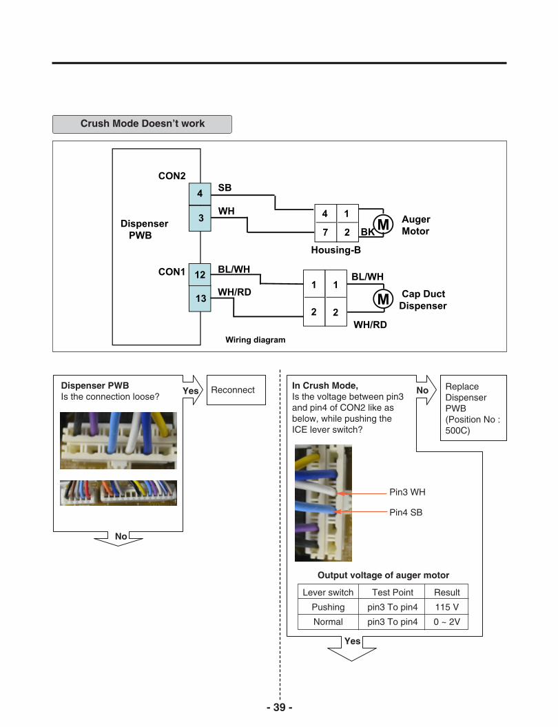
Crush Mode Doesn’t work
Dispenser PWBIs the connection loose?
ReconnectYes In Crush Mode,Is the voltage between pin3and pin4 of CON2 like asbelow, while pushing theICE lever switch?
ReplaceDispenserPWB(Position No :500C)
No
No
Yes
Output voltage of auger motor
Lever switch
Pushing
Normal
Test Point
pin3 To pin4
pin3 To pin4
Result
115 V
0 ~ 2V
Pin3 WH
Pin4 SB

- 40 -
In Crush Mode,Is the voltage betweenpin12 and pin13 of CON1like as below, while pushingthe ICE lever switch?
After plug in, explain to thecustomer!
Is the condition of the microswitch like as below?
ReplaceMicroSwitch(PositionNo: 402C)
NoReplaceDispenserPWB(Position No: 500C)
No
ReplaceAuger Motor(Position No: 606A)
NoIs the resistance valuebetween (1) and (2) of theAuger motor like as below?
Yes
Yes
Status
Normal
Push the Lever
Tester
Infinity
0 Ω
Resistance of Auger Motor
Test Point
(1) To (2)
Result
2.38 ~ 4.02 Ω
Output voltage of dispenser cap duct
Lever switch
Pushing
Normal
Test Point
pin12 To pin13
pin12 To pin13
Result
12 V
0V
Yes
(1) (2)
(1)
(2)
Pin12 BL/WHPin13 WH/RD

- 41 -
Water Mode Doesn’t work
Dispenser PWBIs the connection loose?
ReconnectYes In Water Mode,Is the voltage betweenpin2 and pin11 of CON2 indispenser PWB like asbelow, while pushing theWater lever switch?
ReplaceDispenserPWB(Position No :500C)
No
No
Yes
Output voltage of door water valve
Lever switch
Pushing
Normal
Test Point
pin2 To pin11
pin2 To pin11
Result
115 V
0 V
Pin2 BL
Pin11 PR

- 42 -
In Water Mode,Is the voltage betweenpin2 and pin11 of CON3 inmain PWB like as below,while pushing the level switch?
Is the condition of the microswitch like as below?
Checking resistance of Second-valve
Second Water- valveIs the resistance value ofSecond-water valve like asbelow?
ReplaceSecondWater-valve(Position No :619B)
No
ReplaceMicro Switch(Position No: 279G)
No
ReplaceMAIN PWB(Position No: 500A)
No
ReplaceFirst Water-valve(Position No: 619A)
NoFirst Water- valveIs the resistance valuebetween (1) and (2) of theFirst-water valve like asbelow?
Yes
Yes
Yes
Test Point
(1) To (2)
Result
360 ~ 420 Ω
Checking resistance of First-valve
Test Point
(1) To (2)
Result
360 ~ 420 Ω
Status
Normal
Push the Lever
Tester
Infinity
0 Ω
Main PWBCON3Pin11 GY
Pin2 BL
Output voltage of machine room water valve
Test Point
Pin2 To pin11
Result
115 V
Yes
(1)(2)
(2) PK
(1) YL
(1)
(2)
Machine room
Ice Maker
In door
Door Dispenser
After plug in, explain to the customer!
- 43 -
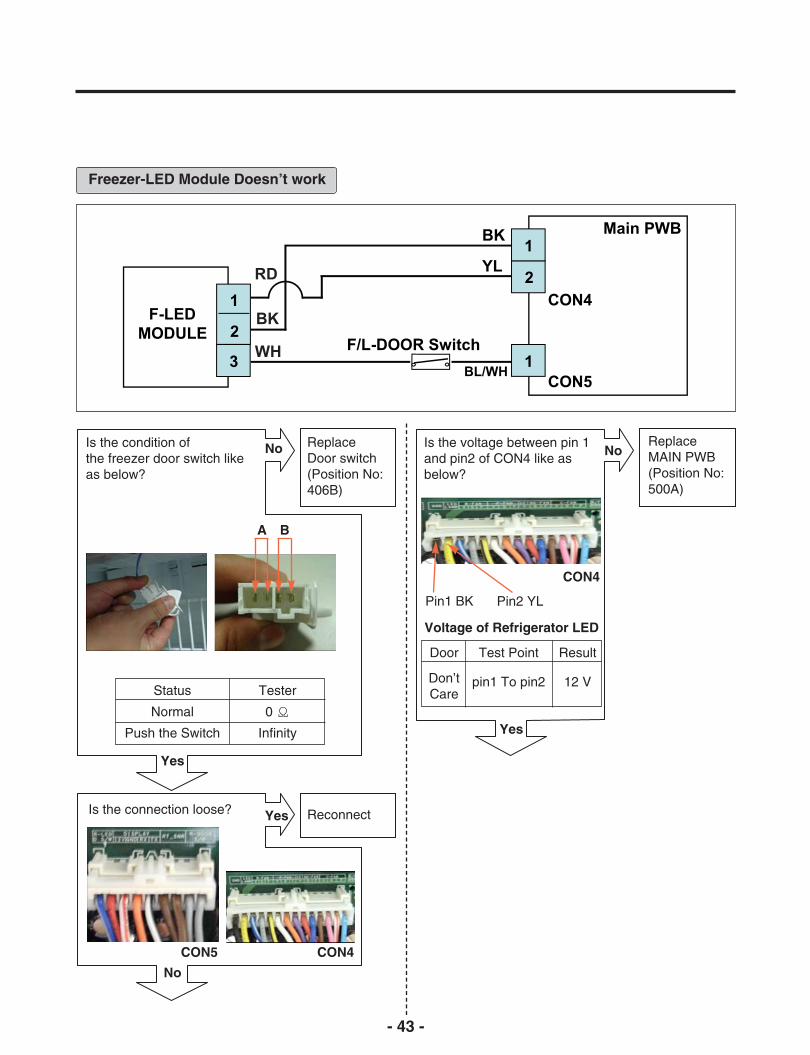
Freezer-LED Module Doesn’t work
Is the condition ofthe freezer door switch likeas below?
Replace Door switch(Position No:406B)
No
Is the connection loose?
CON5 CON4
ReconnectYes
Is the voltage between pin 1and pin2 of CON4 like asbelow?
Replace MAIN PWB(Position No:500A)
No
Yes
No
A B
Status
Normal
Push the Switch
Tester
0 Ω
Infinity Yes
Voltage of Refrigerator LED
Door
Don’tCare
Test Point
pin1 To pin2
Result
12 V
CON4
Pin1 BK Pin2 YL

Is the voltage between pin 1 and pin2 of Freezer LED Module Housing?
1.Check theharness open or short
2.replace FLED Module
Yes
No
Pin2 BK Pin1 RD
Voltage of Freezer LED
Door
Don’t care
Test Point
pin1 To pin2
Result
12 V
- 44 -
- 45 -
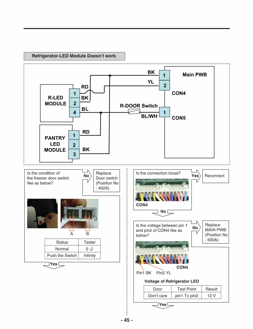
Refrigerator-LED Module Doesn’t work
Is the condition ofthe freezer door switchlike as below?
ReplaceDoor switch(Position No: 402A)
Yes
NoIs the connection loose?
ReconnectYes
No
Yes
CON4
A B
Status
Normal
Push the Switch
Tester
0 Ω
Infinity
Is the voltage between pin 1and pin2 of CON4 like asbelow?
ReplaceMAIN PWB(Position No: 500A)
No
Pin1 BK Pin2 YLCON4
Voltage of Refrigerator LED
Door
Don’t care
Test Point
pin1 To pin2
Result
12 V

- 46 -
Replace R LED Module(Position No : 409D)
Is the voltage betweenpin 1 and pin2 ofRefrigerator LED ModuleHousing?
1.Check theharness openor short 2.replace RLED Module
Yes
No
Pin1 RD Pin2 BK
Voltage of Refrigerator LED
Door
Don’t care
Test Point
pin1 To pin2
Result
12 V
Is the voltage betweenpin 2 and pin3 ofRefrigerator LED ModuleHousing?
1.Check theharness openor short2.replace RLED Module
Yes
No
Pin2 BK Pin3 BL
Voltage of Door S/W Signal
Door
Close
Open
Test Point
pin2 To pin3
pin2 To pin3
Result
0 V
12 V
Is the connection loose?ReconnectYes
No
CON5
Is the voltage between pin 1and 3 of CON5 like as below?
ReplaceMAIN PwB(Position No: 500A)
No
Yes
CON5
Pin1 BL/WH Pin3 WH/RD
Voltage of Door S/W Signal
Door
Don’t care
Test Point
pin1 To pin3
Result
12 V

- 47 -
Poor cooling in the refrigerator compartment
CompressorCheck the compressor Refer to page 51
Enter the TEST 1 MODE
Voltage of R-fan
Test Point
pin3 To pin4
Result
12 ~ 16 V
No
Yes
Is the voltage between pins 3and pin 4 of CON4 like asbelow?
ReplaceMAIN PWB(PositionNo : 500A)
Yes
No
Pin3 BL/WH
Pin4 GY
Feedback voltage of R-fan
Test Point
pin4 To pin5
Result
1 ~ 4 V
Feedback check.Is the voltage between Pin 4and pin 5 of CON4 like asbelow?
ReplaceMAIN PWB(PositionNo : 500A)
Yes
No
Pin4 GY
Pin5 YL/BK
CON4
CON4
- 48 -
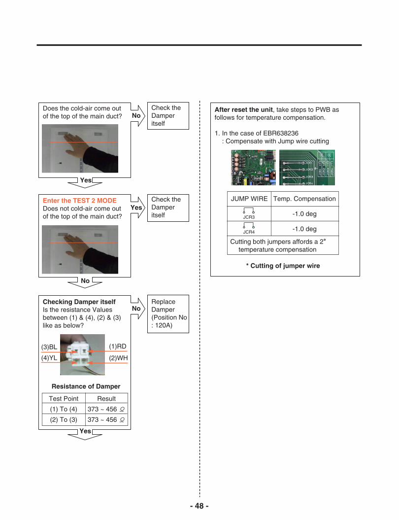
Does the cold-air come outof the top of the main duct?
Check theDamperitself
No
Yes
After reset the unit, take steps to PWB asfollows for temperature compensation.
1. In the case of EBR638236: Compensate with Jump wire cutting
* Cutting of jumper wire
Enter the TEST 2 MODEDoes not cold-air come outof the top of the main duct?
Check theDamperitself
Yes
No
Checking Damper itselfIs the resistance Valuesbetween (1) & (4), (2) & (3)like as below?
ReplaceDamper(Position No: 120A)
No
Yes
(1)RD(3)BL
(4)YL (2)WH
Resistance of Damper
Test Point
(1) To (4)
(2) To (3)
Result
373 ~ 456 Ω
373 ~ 456 Ω
JUMP WIRE
Cutting both jumpers affords a 2。temperature compensation
Temp. Compensation
-1.0 deg
-1.0 deg
JCR3
JCR4

- 49 -
Over cooling in the refrigerator compartment
CompressorCheck the compressor Refer to 4-2-4 of page 17
Enter the TEST 1 MODE
No
Yes
Check the Fan operation byplacing your hand in front ofthe vents to feel for any coldair flow.
ReplaceFan
Yes
No
Door
Open
Closed
Fan-Motor
OFF
ON
Enter the TEST 2 MODEDoes the cold-air coming outof the top of the main duct?
Check theDamperitself
No
Yes
Checking Damper itselfIs the resistance Valuesbetween (1) & (4), (2) & (3)like as below?
ReplaceDamper(Position No: 120A)
No
Yes
(1)RD(3)BL
(4)YL (2)WH
Resistance of Damper
Test Point
(1) To (4)
(2) To (3)
Result
373 ~ 456 Ω
373 ~ 456 Ω

- 50 -
After reset the unit, take steps to PWB asfollows for temperature compensation.
1. In the case of EBR638236: Compensate with Jump wire cutting
* Cutting of jumper wire
JUMP WIRE
Cutting both jumpers affords a 2。temperature compensation
Temp. Compensation
+1.0 deg
+1.0 deg
JCR1
JCR2
Enter the TEST 3 MODEIs the Compressor off?
ReplaceMAIN PWB(PositionNo: 500A)or Compdrive PWB(PositionNo : 360A)
Yes
Yes

- 51 -
1. How To Remove Terminal Position Assurance(TPA)
- After measure the values, you shouldput in the TPA again.
* AC TPA
* DC TPA
3. How To Start Test Mode Push the TEST button on the Main PWB, You canstart the TEST MODE.
2. Wire Color
BL: BlueWH: WhiteBO: Bright OrangeBK: BlackBN: BrownPR: PurpleRD: RedGN: GreenSB: Sky BlueGY: GrayBL/WH : Blue & WhiteWH/RD : White & RedYL/BK : Yellow & Black
* 1 time : Comp / Damper / All FAN on(All things displayed)
[ NOTE ]
TEST BUTTON
- 52 -
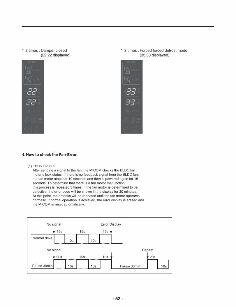
4. How to check the Fan-Error
(1) EBR60028302After sending a signal to the fan, the MICOM checks the BLDC fanmotor s lock status. If there is no feedback signal from the BLDC fan,the fan motor stops for 10 seconds and then is powered again for 15seconds. To determine that there is a fan motor malfunction,this process is repeated 3 times. If the fan motor is determined to bedefective, the error code will be shown in the display for 30 minutes.At this point, the process will be repeated until the fan motor operatesnormally. If normal operation is achieved, the error display is erased andthe MICOM is reset automatically.
No signal Error Display
15s
10s
15s
10s
15s
Normal drive
No signal Repeat
20s
10s
15s
10s Pause 30minPause 30min 10s
15s 20s
* 2 times : Damper closed(22 22 displayed)
* 3 times : Forced forced defrost mode(33 33 displayed)

- 53 -
7. COMPONENT TESTING INFORMATION
7-1. Defrost Controller Assembly
Function - Controller assembly is consist of 2 kinds of part those are fuse-m and sensor. we candecide part is defect or not when we check the resistance.
- Fuse-m can cut off the source when defrost heater operate the unusual high temperature.- Sensor give temperature information to Micom
How toMeasure(Fuse-M)
Set a ohmmeter to the 2 housing pin.Measure the 2 pin connected to Fuse-M.If the ohmmeter indicate below 0.1ohmfuse-m is a good condition, But infinitelygreat ohm Fuse-M is disconnection
How toMeasure(Sensor)
Set a ohmmeter to The 2housing pin.Measure the 2 pin connected to Sensor.If the ohmmeter indicate 11 (at roomtemperature) Sensor is not a defect.When check the ohm at other temperatureCheck the sensor manual.
Standard Sensor (at room temperature)
Test Point
(1) to (2)
Ressult
11Ω
Fuse-M (at all temperature)
Test Point
(1) to (2)
Ressult
0 ~ 0.1Ω
(1) to (2)
(1) to (2)
- 54 -
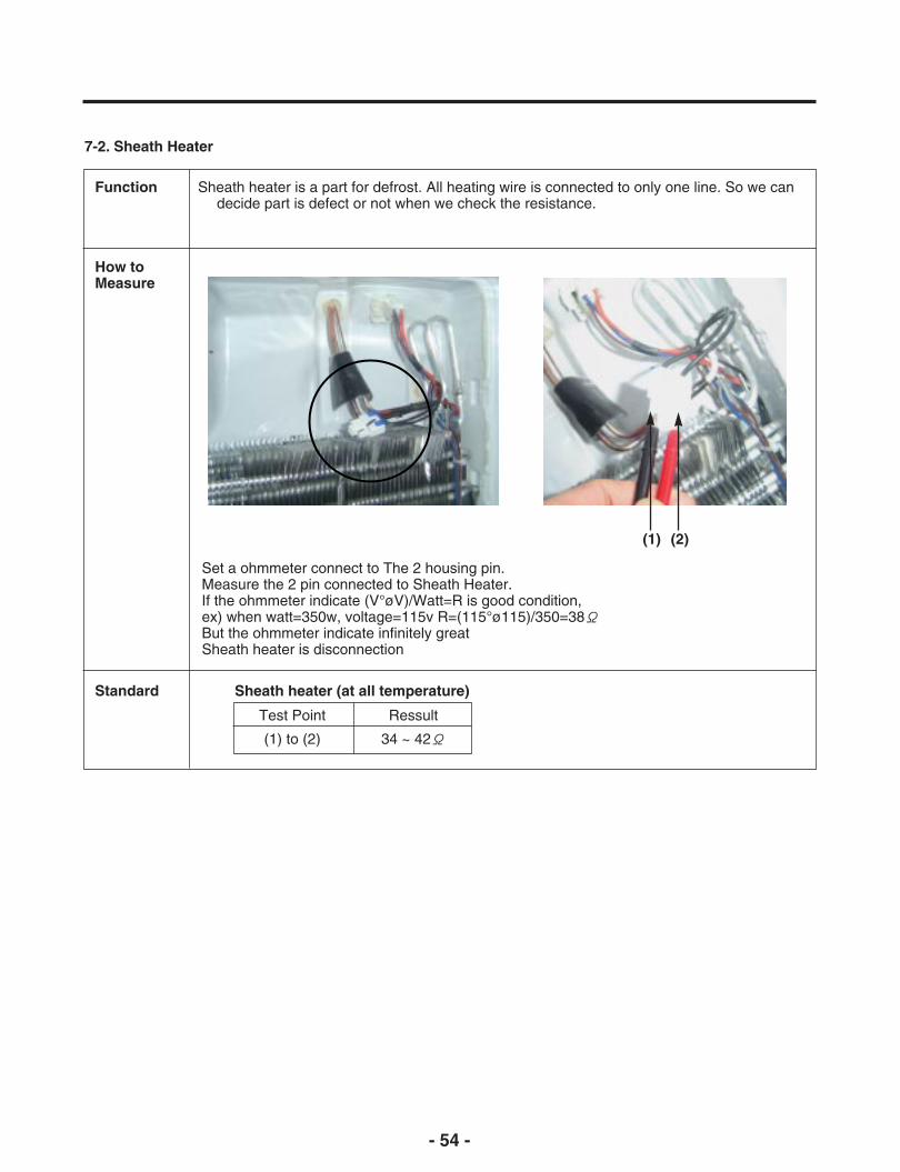
7-2. Sheath Heater
Function Sheath heater is a part for defrost. All heating wire is connected to only one line. So we candecide part is defect or not when we check the resistance.
How toMeasure
Set a ohmmeter connect to The 2 housing pin.Measure the 2 pin connected to Sheath Heater.If the ohmmeter indicate (V°øV)/Watt=R is good condition,ex) when watt=350w, voltage=115v R=(115°ø115)/350=38ΩBut the ohmmeter indicate infinitely greatSheath heater is disconnection
Standard Sheath heater (at all temperature)
Test Point
(1) to (2)
Ressult
34 ~ 42Ω
(1) (2)
- 55 -
1
2
5467
89
3
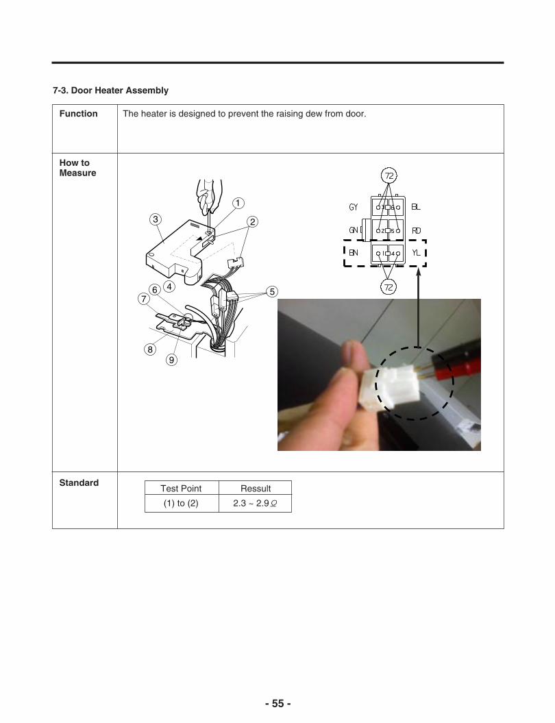
7-3. Door Heater Assembly
Function The heater is designed to prevent the raising dew from door.
How toMeasure
StandardTest Point
(1) to (2)
Ressult
2.3 ~ 2.9Ω
- 56 -
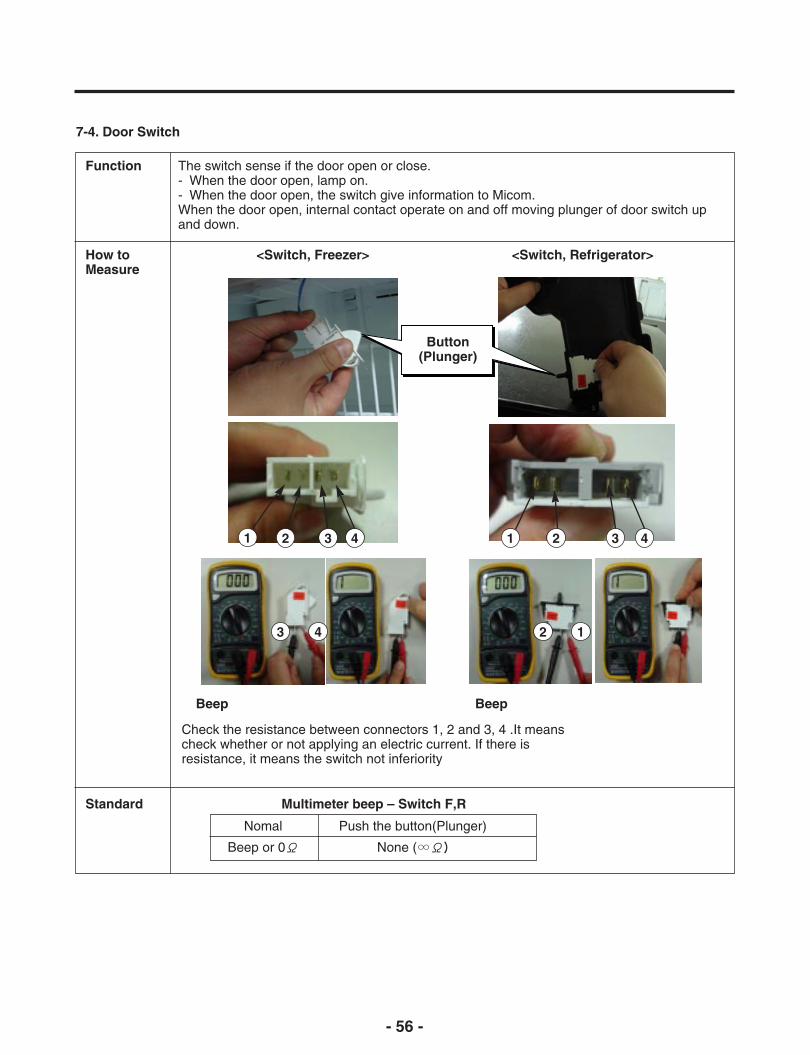
7-4. Door Switch
Function The switch sense if the door open or close.- When the door open, lamp on.- When the door open, the switch give information to Micom.When the door open, internal contact operate on and off moving plunger of door switch upand down.
How toMeasure
<Switch, Freezer> <Switch, Refrigerator>
Check the resistance between connectors 1, 2 and 3, 4 .It meanscheck whether or not applying an electric current. If there isresistance, it means the switch not inferiority
Standard
Beep Beep
Multimeter beep – Switch F,R
Nomal
Beep or 0Ω
Push the button(Plunger)
None (∞Ω)
Button(Plunger)
1 2 3 4
3 4 2 1
1 2 3 4
- 57 -
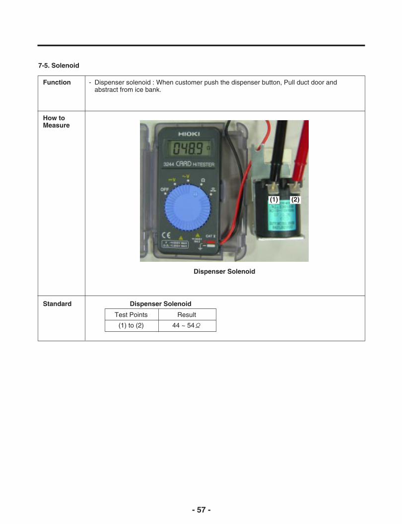
7-5. Solenoid
Function - Dispenser solenoid : When customer push the dispenser button, Pull duct door andabstract from ice bank.
How toMeasure
Standard
Dispenser Solenoid
Dispenser Solenoid
Test Points
(1) to (2)
Result
44 ~ 54Ω
(1) (2)

- 58 -
7-6. AC Motor ASSEMBLY (Geared Motor & Solenoid)
Function The Geared Motor of ac motor assembly advances forward the ice by rotating the ice andThe solenoid of ac motor assembly selects one of the cube mode or crush mode.
- Cube solenoid : Pulling the stir lip for moving the ice in icemaker system.
How toMeasure
< Geared Motor >
T.P
< Geared Motor >
Standard Geared Motor
Test Points
(1) to (2)
Result
2.38 ~ 4.02Ω
Cube Solenoid
Test Points
(3) to (4)
Result
32 ~ 40Ω
Take out the malehousing fromfemale housing
Measure theresistance between(1) and (2)
Check the resistance between connectors (Geared motor 1, 2) and(solenoid 3, 4). It means check whether or not applying anElectric current. If there is resistance, it means the geared motor orsolenoid is not inferiority
Remove thefemale housingfrom terminal.
Measure theres istancebetween (3)and (4)
(1) (2)
(3)
(4)
1
2
1
2
Terminalof solenoid

- 59 -
7-7. Damper
Function The damper supplies the cold air at freezer room to chillroomby using the damper’s plate. Chillroom is colder than beforewhen damper’s plate is open. When damper’s plate is close,chillroom’s temperature will rise.
How toMeasure
< Damper Circuit >
< extension >
Check the ,
Standard Damper
Test Points
Red and Yellow
Result
373 ~ 456Ω
Test Points
Blue and White
Result
373 ~ 456Ω
Check the resistance between connectors 1,3 and 2,4 .It meanscheck whether or not applying an electric current. If there isresistance, it means the damper not inferiority
1 Blue 1 Blue
2 Red
3 White
3 White
1 3
Check the , 2 4 Check the , 1 3
3 Yellow
- 60 -
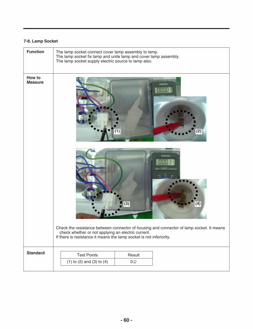
7-8. Lamp Socket
Function The lamp socket connect cover lamp assembly to lamp.The lamp socket fix lamp and unite lamp and cover lamp assembly.The lamp socket supply electric source to lamp also.
How toMeasure
Standard
Check the resistance between connector of housing and connector of lamp socket. It meanscheck whether or not applying an electric current.
If there is resistance it means the lamp socket is not inferiority.
Test Points
(1) to (2) and (3) to (4)
Result
0Ω
(1) (2)
(3) (4)

- 61 -
7-9. Water Valve
Function - First-Water Valve (in machine room): supply the water from city water to water filter in refrigerator
- Second-Water Valve (in door): supply the water from water filter to icemaker and dispenser
How toMeasure
Standard
First-water valve(in machine room)
second-water valve(in door)
Dispense Ice Maker
Test Points
(1) to (2)
Result
360 ~ 420Ω

- 62 -
8. TROUBLESHOOTING
8-1 COMPRESSOR AND ELECTRIC COMPONENTS
1 YES
YES
NO
2
5
5
3
5
1
43
2
3
Power source.Remove TSD-Starterfrom compressor andmeasure voltagebetween terminal C ofcompressor andterminal 5 or 6 of TSD.
(Rated voltage±10%)?
No voltage. OLP disconnected?
Applied voltage isn'tin acceptable range.(115V ±10%)
Check resistancebetween M-C, S-C andM-S in motorcompressor.
Checkresistance ofTSD-Starter.
Check resistance oftwo terminals inTSD-Starter.
Refer to page 12.
4 Check OLP. Check resistance of twoterminals in OLP.
Supplyvoltage ratingwith ±10%.
5 Checkstarting state.
Check the power supplyunder load.(Compressor attemptingto re-start after being offfor 5 minutes).
Replacecompressor.
The range of resistance is between 1~50Ω (ok)
Open or short
Checkresistance ofmotorcompressor.
Advise customer thatpower supply needsto be checked by anelectrician.
Replace OLP.
Check connectioncondition.
Reconnect.
COMPRESSOR DOES NOT SWITCH ON ORSTOPS DURING RUNNING:• Check if the connections have been properly
inserted;(see Assembly Instruction Item for details).
• Check the voltage between TSD terminal “L”and “N”.
• The voltage should be according to theTechnical Specification Item.
• Check if the overload protector is tripping. Ifthis occurs, check the Table of MainRefrigeration Problems. (CompressorApplication Manual from Embraco).
• If you have done all the items above and theproblem persist, change the TSD.
NOTE: For further details, please check theCompressor Application Manual-Embraco.

- 63 -
8-2 TSD AND OLP
Normal operation ofcompressor isimpossible or poor.
Separate TSD-Starterfrom compressor andmeasure resistancebetween No. 5 and 6of PTC-Starter with atester.(Figure 19)
Separate OLP fromcompressor and checkresistance valuebetween two terminalsof OLP with a tester.(Figure 20)
Check anotherelectric component.
Replace OLP.
Shows continuity
Open
Figure 19 Figure 20
Observation value is115V/60Hz : 6.8Ω±30%
Replace TSD-Starter.
The resistance valueis 0Ω (short) or
(open).

- 64 -
8-3 SERVICE DIAGNOSIS CHART
COMPLAINT POINTS TO BE CHECKED REMEDY
No Cooling. • Is the power cord unplugged from the outlet?• Check if the power switch is set to OFF.• Check if the fuse of the power switch is shorted.• Measure the voltage of the power outlet.
• Plug into the outlet.• Set the switch to ON.• Replace the fuse.• If the voltage is low, correct the wiring.
Cools poorly. • Check if the unit is placed too close to the wall.• Check if the unit is placed too close to the stove,
gas cooker, or in direct sunlight.• Is the ambient temperature too high or the room
door closed?• Check if food put in the refrigerator is hot.• Did you open the door of the unit too often or
check if the door is sealed properly?• Check if the Control is set to Warm position.
• Place the unit about 4 inches (10 cm) fromthe wall.
• Place the unit away from these heat sources.• Lower the ambient temperature.
• Put in foods after they have cooled down.• Don't open the door too often and close it
firmly.• Set the control to Recommended position.
Food in theRefrigeratoris frozen.
• Is food placed in the cooling air outlet?
• Check if the control is set to colder position.• Is the ambient temperature below 41°F(5°C)?
• Place foods in the high-temperature section.(front part)
• Set the control to Recommended position.• Set the control to Warm position.
Condensationor ice formsinside the unit.
• Is liquid food sealed?• Check if food put in the refrigerator is hot.• Did you open the door of the unit too often or
check if the door is sealed properly?
• Seal liquid foods with wrap.• Put in foods after they have cooled down.• Don't open the door too often and close it
firmly.
Condensationforms in theExterior Case.
• Check if the ambient temperature and humidity ofthe surrounding air are high.
• Is there a gap in the door gasket?
• Wipe moisture with a dry cloth. It willdisappear in low temperature and humidity.
• Fill up the gap.
There isabnormal noise.
• Is the unit positioned in a firm and even place?
• Are any unnecessary objects placed in the backside of the unit?
• Check if the Drip Tray is not firmly fixed.• Check if the cover of the compressor enclosure in
the lower front side is taken out.
• Adjust the Leveling Screw, and position therefrigerator in a firm place.
• Remove the objects.
• Fix the Drip Tray firmly in the original position.• Place the cover in its original position.
Door does notclose well.
• Check if the door gasket is dirty with an item likejuice.
• Is the refrigerator level?
• Is there too much food in the refrigerator?
• Clean the door gasket.
• Position in a firm place and level the LevelingScrew.
• Make sure food stored in shelves does notprevent the door from closing.
Ice and foodssmellunpleasant.
• Check if the inside of the unit is dirty.• Are foods with a strong odor unwrapped?• The unit smells of plastic.
• Clean the inside of the unit.• Wrap foods that have a strong odor.• New products smell of plastic, but this will go
away after 1-2 weeks.
Other possible problems:
Check if frost formsin the freezer.
Check therefrigeration system.
Check theThermistor.
Notdefrosting
The systemis faulty.
The operation of theThermistor is incorrect.
Check Components ofthe defrosting circuit.
Perform sealedsystem repair.
Replace theThermistor.

- 65 -
8-4 REFRIGERATION CYCLE
Troubleshooting Chart
PARTIALLEAKAGE
Freezercompartment andRefrigerator don'tcool normally.
Low flowing sound ofRefrigerant is heardand frost forms ininlet only.
A little higher thanambienttemperature.
• Refrigerant level is low dueto a leak.
• Normal cooling is possible byrestoring the normal amountof refrigerant and repairingthe leak.
COMPLETELEAKAGE
Freezercompartment andRefrigerator don'tcool normally.
Flowing sound ofrefrigerant is notheard and frost isn'tformed.
Equal to ambienttemperature.
• No discharging ofRefrigerant.
• Normal cooling is possible byrestoring the normal amountof refrigerant and repairingthe leak.
LEA
KA
GE
PARTIALCLOG
Freezercompartment andRefrigerator don'tcool normally.
Flowing sound ofrefrigerant is heardand frost forms ininlet only.
A little higher thanambienttemperature.
• Normal discharging of therefrigerant.
• The capillary tube is faulty.
WHOLECLOG
Freezercompartment andRefrigerator don'tcool.
Flowing sound ofrefrigerant is notheard and frost isn'tformed.
Equal to ambienttemperature.
• Normal discharging of theRefrigerant.
MOISTURE CLOG Cooling operationstops periodically.
Flowing sound ofrefrigerant is notheard and frost melts.
Lower than ambienttemperature.
• Cooling operation restartswhen heating the inlet of thecapillary tube.
CLO
GG
ED
BY
DU
ST
COMP-RESSION
Freezer andRefrigerator don'tcool.
Low flowing sound ofrefrigerant is heardand frost forms ininlet only.
A little higher thanambienttemperature.
• Low pressure at high side ofcompressor due to lowrefrigerant level.
NO COMP-RESSION
No compressingoperation.
Flowing sound ofrefrigerant is notheard and there isno frost.
Equal to ambienttemperature.
• No pressure in the highpressure part of thecompressor.
DE
FE
CT
IVE
CO
MP
RE
SS
ION
CAUSE REMARKSSTATE OF THEEVAPORATOR
TEMPERATUREOF THE
COMPRESSOR
STATE OFTHE UNIT
8-4-1 Cleaning
There is no need for routine condenser cleaning in normal Home operating environments. If the environment isparticularly greasy or dusty, or there is significant pet traffic in the home, the condenser should be cleanedevery 2 to 3 months to ensure maximum efficiency.
If you need to clean the condenser:
Remove the mechanical cover.Use a vacuum cleaner with a soft brush to clean the grille, the open areas behind the grille and the front
surface area of the condenser.Replace the mechanical cover.
- 66 -
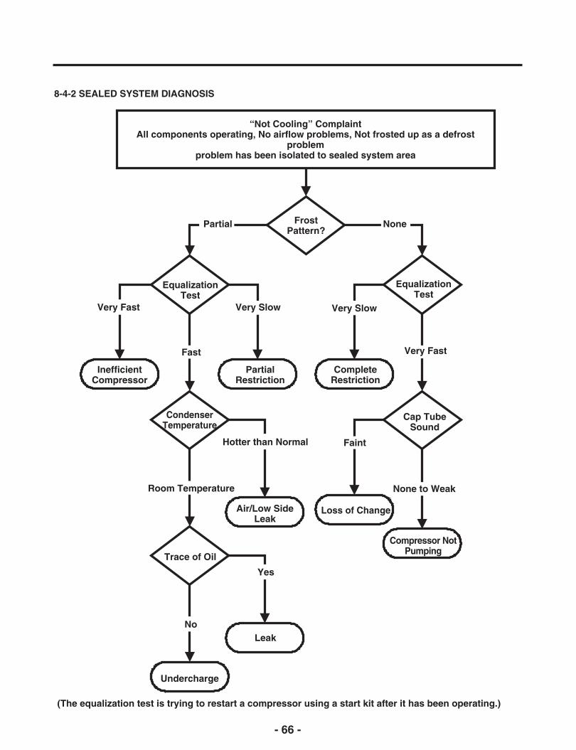
8-4-2 SEALED SYSTEM DIAGNOSIS
“Not Cooling” ComplaintAll components operating, No airflow problems, Not frosted up as a defrost
problemproblem has been isolated to sealed system area
FrostPattern?
Partial
EqualizationTest
Very Slow
None
EqualizationTest
Very FastFast
Very Fast
InefficientCompressor
PartialRestriction
CompleteRestriction
CondenserTemperature
Cap TubeSound
Yes
No
Air/Low SideLeak
Loss of Change
Very Slow
FaintHotter than Normal
None to WeakRoom Temperature
Compressor NotPumping
Trace of Oil
Undercharge
(The equalization test is trying to restart a compressor using a start kit after it has been operating.)
Leak
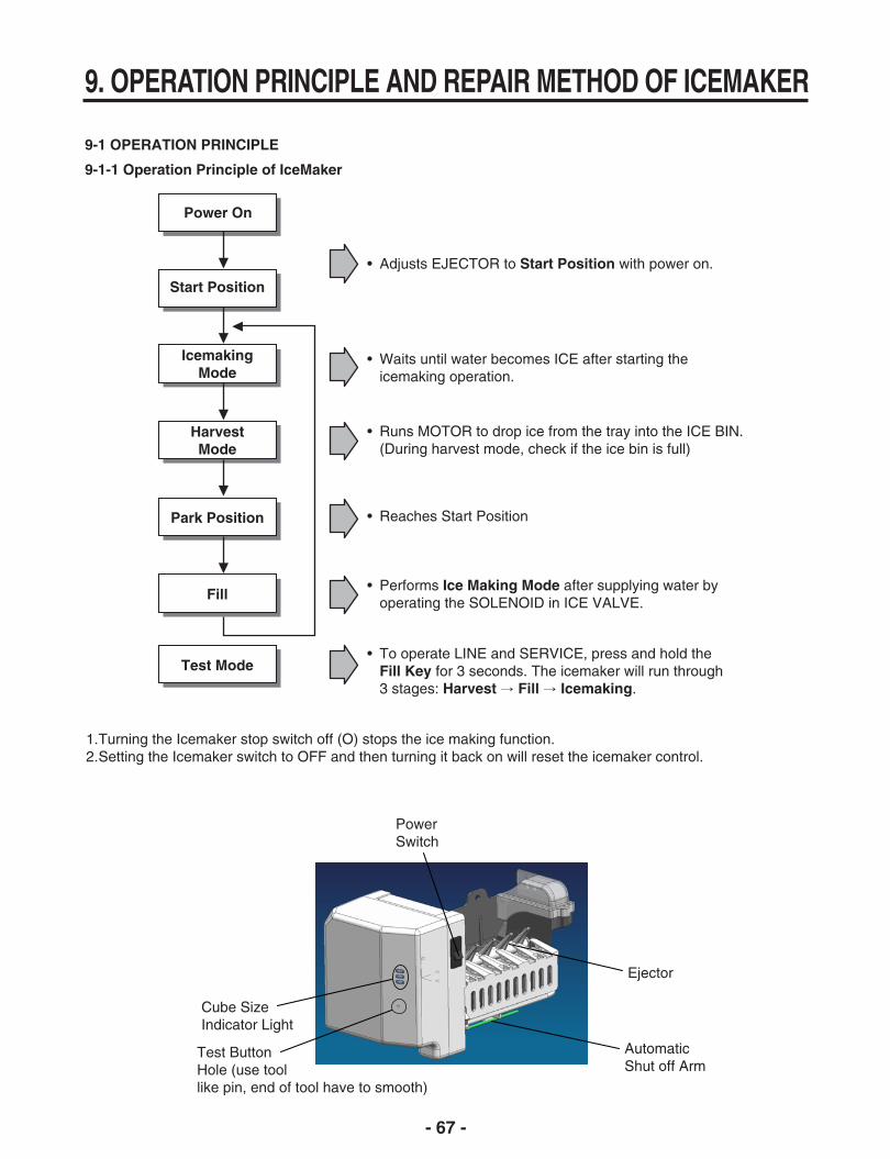
Cube SizeIndicator Light
Test ButtonHole (use toollike pin, end of tool have to smooth)
Power Switch
AutomaticShut off Arm
Ejector
- 67 -
9. OPERATION PRINCIPLE AND REPAIR METHOD OF ICEMAKER
9-1 OPERATION PRINCIPLE
9-1-1 Operation Principle of IceMaker
Power On
Start Position
• Adjusts EJECTOR to Start Position with power on.
IcemakingMode
• Waits until water becomes ICE after starting theicemaking operation.
HarvestMode
• Runs MOTOR to drop ice from the tray into the ICE BIN.(During harvest mode, check if the ice bin is full)
Park Position • Reaches Start Position
Fill• Performs Ice Making Mode after supplying water by
operating the SOLENOID in ICE VALVE.
Test Mode• To operate LINE and SERVICE, press and hold the
Fill Key for 3 seconds. The icemaker will run through 3 stages: Harvest → Fill → Icemaking.
1.Turning the Icemaker stop switch off (O) stops the ice making function.2.Setting the Icemaker switch to OFF and then turning it back on will reset the icemaker control.

- 68 -
9-2 ICE MAKER FUNCTIONS
9-2-1. Icemaking Mode
1. Icemaking refers to the freezing of supplied water in the ice tray. Complete freezing is assured by measuring thetemperature of the Tray with Icemaking SENSOR.
2. Icemaking starts after completion of the water fill operation.3. The Ice Making function is completed when the sensor reaches 19°F (-7°C), 55 minutes after starting.
NOTE : After Icemaker Power is ON, the Icemaker heater will be on for test for 6 sec.
9-2-2. Harvest Mode
If the EJECTOR does not rotate once within 5 minutes in B mode, separate heater control mode starts operating toprevent the EJECTOR from being constrained. (It is recommended that the user open for ice to return to normal mode.)
1. Harvest (Ice removing) refers to the operation of dropping ices into the ice bin from the tray when icemaking hascompleted.
2. Harvest mode:(1) The Heater is ON for 30 seconds, then the motor starts.(2) The feeler arm senses the quantity of ice in the ice storage bin while rotating with the EJECTOR.
A. Ice storage bin is full : The EJECTOR stops (heater off).B. Ice storage bin is not full : The EJECTOR rotates twice to open for ice.
9-2-3. Fill/Park Position
1. Once a normal harvest mode has been completed, the water solenoid will be activated.2. The amount of water is adjusted by pressing the Fill Key repeatedly. This changes the time allowed for fill as illustrated in
the table below.
STAGE TIME TO SUPPLY INDICATIONS REMARKS
1 4.5 sec.
The water amount will varydepending on the water controlSwitch setting, as well as thewater pressure of the connectedwater line.
Water supply amount TABLE
2 4.7 sec.
3 5.0 sec.

- 69 -
9-2-4 Function TEST
1. This is a forced operation for TEST, Service, cleaning, etc. It is operated by pressing and holding the Fill Key for 3seconds.
2. The test works only in the Icemaking Mode. It cannot be entered from the Harvest or Fill mode.3. Caution! If the test is performed before water in the icemaker is frozen, the ejector will pass through the water. When the
Fill mode begins (Stage 4), unless the water supply has been shut off, added water will overflow into the ice bin. If thecontrol doesn’t operate normally in the TEST mode, check and repair as needed.
4. After water is supplied, the normal CYCLE is followed: icemaking → Harvest → Park Position → Fill.5. Five seconds after Stage 5 is completed, the Ice Maker returns to MICOM control. The time needed to supply water
resets to the pre- test setting.
STAGE ITEMS INDICATOR REMARKS
1 HEATERFive seconds after heater starts, aheater will go off if the temperature bysensor is higher than 10°C
Diagnosis TABLE
2 MOTORFive seconds after heater starts, youcan confirm that a motor is moving.
3 HALL IC ICheck if Ice Bin is full or not.If Ice bin is full, the motor and heater areoff and on stand by until Ice bin is empty.
4 HALL IC II You can confirm HALL IC detection ofstart position.
5 VALVE Two seconds after detection of startposition, you can confirm that valve is on.
6 ResetFive seconds after fifth stage iscompleted, The icemaker resets to initialstatus.
Return to Status prior toTEST MODE
NO DIVISION INDICATOR REMARKS
1 Normal Display switch operatesproperly
Mark time to supply
2Icemaking
Sensormalfunction
Make sure that the wire oneach sensor is connected.
CONTENTS
None
Open or short-circuited wire
9-3 DEFECT DIAGNOSIS FUNCTION
9-3-1 ERROR CODES shown on Ice Maker water supply control panel
- 70 -
10. DESCRIPTION OF FUNCTION & CIRCUIT OF MICOM
10-1 Function
10-1-1 Function
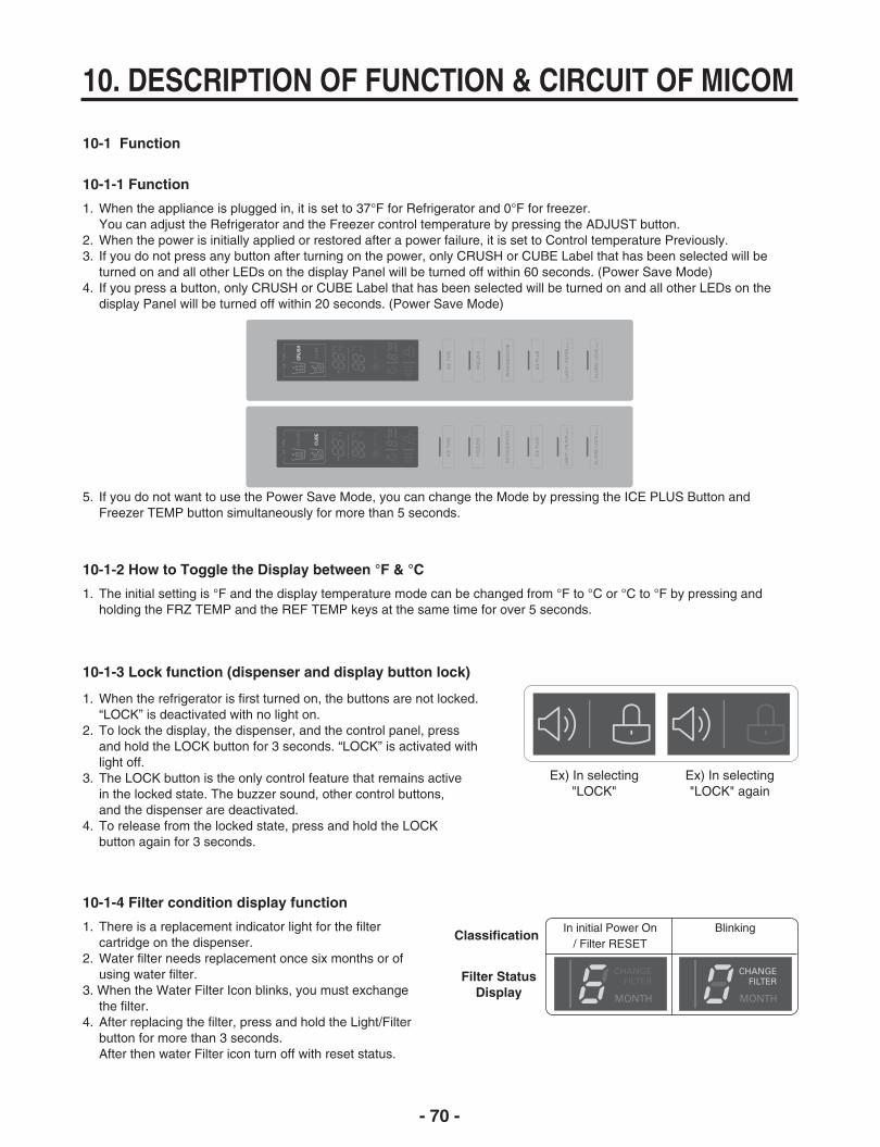
1. When the appliance is plugged in, it is set to 37°F for Refrigerator and 0°F for freezer.You can adjust the Refrigerator and the Freezer control temperature by pressing the ADJUST button.
2. When the power is initially applied or restored after a power failure, it is set to Control temperature Previously.3. If you do not press any button after turning on the power, only CRUSH or CUBE Label that has been selected will be
turned on and all other LEDs on the display Panel will be turned off within 60 seconds. (Power Save Mode)4. If you press a button, only CRUSH or CUBE Label that has been selected will be turned on and all other LEDs on the
display Panel will be turned off within 20 seconds. (Power Save Mode)
10-1-2 How to Toggle the Display between °F & °C
1. The initial setting is °F and the display temperature mode can be changed from °F to °C or °C to °F by pressing andholding the FRZ TEMP and the REF TEMP keys at the same time for over 5 seconds.
10-1-3 Lock function (dispenser and display button lock)
1. When the refrigerator is first turned on, the buttons are not locked.“LOCK” is deactivated with no light on.
2. To lock the display, the dispenser, and the control panel, pressand hold the LOCK button for 3 seconds. “LOCK” is activated withlight off.
3. The LOCK button is the only control feature that remains activein the locked state. The buzzer sound, other control buttons,and the dispenser are deactivated.
4. To release from the locked state, press and hold the LOCKbutton again for 3 seconds.
Ex) In selecting"LOCK"
Ex) In selecting"LOCK" again
5. If you do not want to use the Power Save Mode, you can change the Mode by pressing the ICE PLUS Button andFreezer TEMP button simultaneously for more than 5 seconds.
10-1-4 Filter condition display function
1. There is a replacement indicator light for the filtercartridge on the dispenser.
2. Water filter needs replacement once six months or ofusing water filter.
3. When the Water Filter Icon blinks, you must exchangethe filter.
4. After replacing the filter, press and hold the Light/Filterbutton for more than 3 seconds.After then water Filter icon turn off with reset status.
In initial Power On/ Filter RESET
Blinking
Filter StatusDisplay
Classification

- 71 -
10-1-5 Ice Plus selection
Please select this function for quick freezing.• When you press the Ice Plus Button, the Ice Plus ICON will be
turned on again.• Ice Plus function automatically turns off after a fixed time passes.
10-1-6 Dispenser use selection
You can select water or ice by separated pad switch.
• When you press ice type button, ice type will be changed. (Crush orCube)
• Hold your cup in the dispenser for a few seconds after dispensingice or water to allow the last pieces of ice drops of water to fall intothe cup.
• When after initially establ ishing the water comes out, the water tankinside fills and until at the time of quality the hour is caught.
10-1-7 CONTROL OF FREEZER FAN MOTOR
1. Freezer fan motor has high and standard speeds.2. High speed is used at power-up, for Ultra Ice, and when refrigerator is overloaded.
Standard speeds is used for general purposes.3. To improve cooling speed, the RPM of the freezer fan motor change from normal speed to high.4. High speed (2700RPM) : Initial power on or load corresponding operation, Ultra Ice.
Normal speed (2400RPM) : General working conditions.
10-1-8 Cooling Fan Motor
1. The cooling fan is switched ON and OFF in conjunction with the compressor.2. The cooling fan Motor has high and standard speeds. (When room temper rapture more high then 38°C speed is high)3. The Failure sensing method is the same as in the fan motor of the freezing fan motor(refer to failure diagnosis function
table for failure display).
10-1-9 Ice Compartment Fan
1. The Icing Fan is controlled by the the sensor on the top of the ice compartment.2. The Failure sensing method is the same as in the fan motor of the freezer
(refer to failure diagnosis function table for failure display)
10-1-10 Refrigeration room Fan Motor
1. The refrigeration room fan is switched ON and OFF in conjunction with the refrigeration room temperature.2. The Failure sensing method is the same as in the fan motor of the freezing fan motor (refer to failure diagnosis function
table for failure display).
WATER PADICE PAD

- 72 -
10-1-11 Ice PLUS
1. The purpose of this function is to intensify the cooling speed of freezer and to increase the amount of ice.2. Whenever selection switch is pressed, selection/release, the Icon will turn ON or OFF.3. If there is a power outage and the refrigerator is powered on again, Ice PLUS will be canceled.4. To activate this function, press the Ice PLUS key and the Icon will turn ON. This function will remain activated for 24 hrs.
The first three hours the compressor and Freezer Fan will be ON. The next 21 hours the freezer will be controlled at thelowest temperature. After 24 hours or if the Ice PLUS key is pressed again, the freezer will return to its previoustemperature.
5. During the first 3 hours :(1) Compressor and freezer fan (HIGH RPM) run continuously.(2) If a defrost cycle begins during the first 90 minutes of Ice Plus, the Ice PLUS cycle will complete its cycle after
defrosting has ended.If the defrost cycle begins when Ice Plus has run for more than 90 minutes, Ice PLUS will run for two hours after the defrost is completed.
(3) If Ice PLUS is pressed during defrost, Ice Plus Icon is on but this function will start seven minutes after defrost iscompleted and it shall operate for three hours.
(4) If Ice Plus is selected within seven minutes after compressor has stopped, the compressor (compressor delays seven minutes) shall start after the balance of the delay time.
(5) The fan motor in the freezer compartment runs at high speed during Ice Plus.6. For the rest of the 21 hours, the freezer will be controlled at the lowest temperature.
10-1-12 How to set the display mode and cancel it
1. With the refrigerator door open, keep pressing the Refrigerator Temp Button and ICE PLUS Button more than 5 seconds,then it goes to the display mode with Special Beep Sound.
2. Perform the same way again to cancel the display mode.3. All Freezing unit will be turned off at display mode (Exceptions : Lamp, Display)
10-1-13 Defrosting (removing frost)
1. Defrosting starts each time the COMPRESSOR running time Betwee 7~50 hours.2. For initial power on or for restoring power, defrosting starts when the compressor running time reaches 4 hours.3. Defrosting stops if the sensor temperature reaches 46.4°F(8°C) or more. If the sensor doesn’t reach 46.4°F(8°C) in 1
hours, the defrost mode is malfunctioning. (Refer to the defect diagnosis function, 8-1-15.)4. Defrosting won’t function if its sensor is defective (wires are cut or short circuited)

- 73 -
10-1-15 Auto pantry
1. The temperature control will automatically start upon the selected Auto Pantry temperature control.2. You can adjust the Pantry control with three different temperature ranges by pressing the Temp.Selector button.
10-1-14 Defect Diagnosis Function
1. Automatic diagnosis makes servicing the refrigerator easy.2. When a defect occurs, the buttons will not operate; but the tones. such as ding. will sound.3. When the defect CODE removes the sign, it returns to normal operation (RESET).4. The defect CODE shows on the Refrigerator and Freezer Display.
* Display check function: If simultaneously pressing Ultra Ice button and freezing temperature adjustment button for a second, display LCD graphics on. If releasing the button, the LCD graphic displays the previous status.You can check the error code Within 3-hour Period from initial error
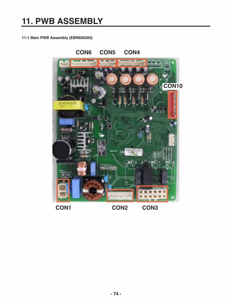
- 74 -
11. PWB ASSEMBLY
11-1 Main PWB Assembly (EBR600283)
CON6
CON1 CON2 CON3
CON5 CON4
CON10

- 75 -
11-2 Display and Dispenser Drive PCB Assembly
Display PWB
CON104
CON103
CON102
CON101

- 76 -
CON1CON3
CON2

11. EXPLODED VIEW & REPLACEMENT PARTS LISTCASE PARTSCAUTION: Use the part number to order part, not the position number.
603C603B
626A624G
607A
624C
S01
103B
103AS01
S02
501F
624A
S03
B01
271B
207B
503D
503E
S11
503G
409D
158A
S11
120C
145A
282G
405E329B
405C
405F
405G
405D
404B
405H
S14
B02
405I282F
405H
404A
405B
329A
405C
405F
407A
S17
103C
315A
315C
315B
106A
409E
503F
106A
S14
313A
411A
500A
410G
S02
271DS10
145B
S11
406D
B01
610D
402A
S03
207A
158B
315B
315C
B04
120B
402A
B02 249C
262B
262H
249D
310B
312A
300A314A
317A
303A
303B 303C
318A
105A
304A
309B 329C
323B
319A
319C
S20
420A
312C
302B
400A
408A
406B
120A
332C
405J
610E

- 2 -
133B
131A
133B
145F
133B
136B
237C
136A
133A
132P
145C
136C
FREEZER PARTSCAUTION: Use the part number to order part, not the position number.
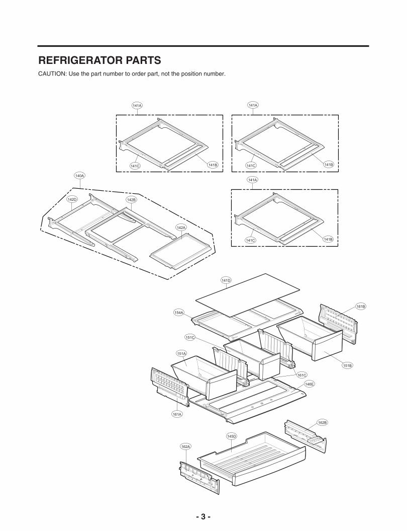
- 3 -
140A
142D 142B
141A
141C 141B
142A
154A
141D
161B
151B
161C
146E
162B
145D
162A
161A
151A
151C
141A
141C 141B
141A
141C 141B
REFRIGERATOR PARTSCAUTION: Use the part number to order part, not the position number.
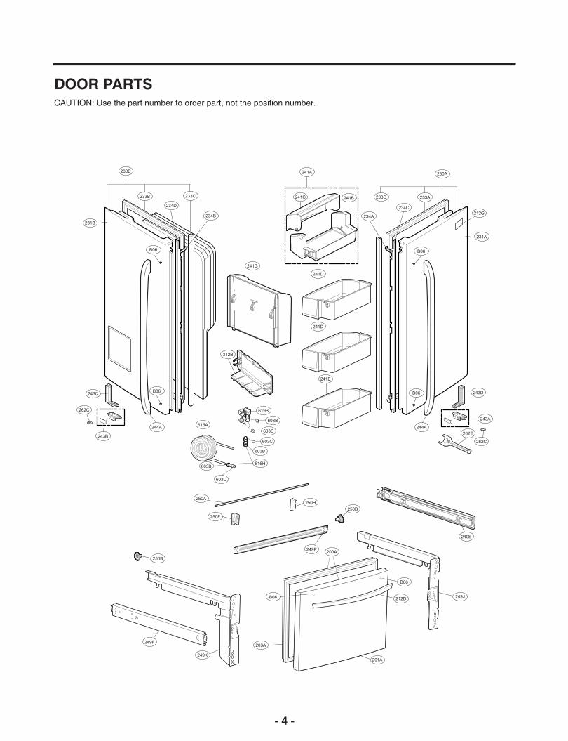
- 4 -
230B
233B
234D
233C
234B
B06
B06243C
244A
243B
312B
241G
241D
241D
241E
B06 243D
243A
262E
244A
241C
241A
241B
234A
233D
234C
233A
230A
212G
B06
249K
203A
B06
250A
250F
212D
B06
249J
250B
249F
250B
249E
615A
603C
603B
619B
616H
603B
603C
603C
603B
262C
262C
200A249P
250H
201A
231B
231A
DOOR PARTSCAUTION: Use the part number to order part, not the position number.

- 5 -
276A
276B
405A
279I
278B
279H
279J
402C
402C
278C
402C
278C
501D
279B
281A
278D
279D
500C
279E
501A
279A
279C
281B
275A
DISPENSER PARTSCAUTION: Use the part number to order part, not the position number.

- 6 -
617A
625A
616G
623B
616J
616G
623B
616J
603C
616D
616D
S31
616F
627B
S31
619A
619E
627A
S31
603B
ICE & WATER PARTSCAUTION: Use the part number to order part, not the position number.
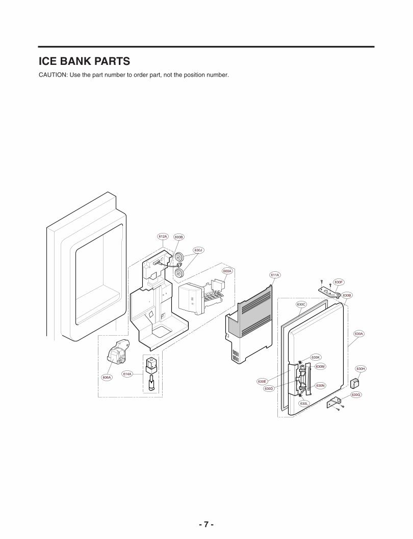
- 7 -
ICE BANK PARTSCAUTION: Use the part number to order part, not the position number.
612A 600B
630J
600A
614A606A
611A
630F
630B
630A
630H
630G
630N
630L
630M
630K
630E
630D
630C

- 8 -
P/No. MFL62188009 NOV. 2011 Printed in Korea