refrigerant detection system installation manual
TRANSCRIPT

Rev 1.03 Jan 2005
Refrigerant Detection System
Installation Manual
Preliminary copy CPC (UK) Ltd. Unit 7&8 Heathrow Causeway Est. Ariel Way, Hounslow, Tel: 0208 630 2270 Middlesex. TW4 6JW Fax: 0208 630 2271
Refigerant Detection System – Installation Manual – Rev 1.03 Jan 2005
2 of 28
INDEX 1 BRIEF DESCRIPTION OF PARTS
1.1 IRLDS Analyser Panel
1.2 Coldroom Refrigerant Leak Alarm Panel
1.2.1 Type 1
1.2.2 Type 2
1.3 Filters
1.3.1 In-line
1.3.2 End-of-line
1.4 Manifolds
1.4.1 Two Way
1.4.2 Three Way
1.4.3 Four Way
1.5 Sampling Tube
1.6 Other Fittings
1.6.1 Vent line
1.6.2 Straight connector
1.6.3 Filter bracket
1.6.4 Beacons
1.6.5 Lampshade collector
2 CHOOSING PANEL POSITIONS
2.1 IRLDS Analyser Panel Location
2.2 Coldroom Refrigerant Leak Alarm Panel Location

Refigerant Detection System – Installation Manual – Rev 1.03 Jan 2005
3 of 28
3 CHOOSING END-OF-LINE POSITIONS
4 READING THE INSTALLATION SCHEDULE
5 INSTALLING SAMPLING TUBE
5.1 Main tube run
5.2 Manifolding
5.3 Packs and Coldrooms
6 STANDARD WIRING & NETWORK DIAGRAMS
6.1 Tesco New Store
6.2 Tesco Refit with Einstein front end
6.3 Tesco Refit with Woodley front end
6.4 Tesco Europe store
6.5 Waitrose store

Refigerant Detection System – Installation Manual – Rev 1.03 Jan 2005
4 of 28
SECTION 1 : BRIEF DESCRIPTION OF PARTS
1.1 IRLDS Analyser Panel Part Number : 885400-006 8 channel Freon Analyser
885400-111 8 channel Ammonia Analyser
885400-004 16 channel Freon Analyser
885400-110 16 channel Ammonia Analyser
The Analyser panel is the main part of the refrigerant detection system. The panel is
available with either 8 or 16 channels and can be fitted with an infrared bench for
either standard CFC, HCFC or HFC refrigerants or an infrared bench for ammonia.
Each panel is fitted with a pump to draw air samples back from each sampling
location to the infrared bench and a waterbowl with a float switch to protect the panel
in case of accidental ingress of water into the sampling tube.
1.2 Coldroom Refrigerant Leak Alarm Panel
1.2.1 Type 1 Part Number : 000-070 8 output channels
000-080 16 output channels
The Coldroom Refrigerant Leak Alarm panel type 1 is designed for use on either a
stand alone refrigerant detection system or a system connected to a third party BMS
or refrigeration alarm panel. It is available with either 8 or 16 outputs and will provide
24Vdc through individual channels as switched by the analyser panel.
1.2.2 Type 2 Part Number : 000-010 7 output channels
000-020 15 output channels
The Coldroom Refrigerant Leak Alarm panel type 2 is designed for use specifically
with a refrigerant detection system connected to a CPC Einstein refrigeration alarm
panel. It is available with either 7 or 15 ouputs and will provide 24Vdc through
individual channels as switched by the Einstein panel.


Refigerant Detection System – Installation Manual – Rev 1.03 Jan 2005
6 of 28
1.3 Filters
1.3.1 Inline Filter Part Number : 272-0621
The Inline Filter is fitted with a fine filtration element and is used to prevent the
ingress of dust particles, etc. into the analyser panel. The inline filters are fitted
underneath the analyser panel and a separate filter is used for every sampling channel
that is occupied on the analyser panel.
1.3.2 End of Line Filter Part Number : 44-5100
The End of Line Filter is fitted with a slightly coarser filtration element than the inline
filter and is used to prevent the ingress of dust and dirt particles into the sampling
tube. End of line filters are fitted at each open end of tube local to the sampling
locations that are to be monitored.
1.4 Manifolds
1.4.1 2 Way Manifold Part Number : 44-5102
The 2 Way Manifold is a Y-piece that is used to split the sampling tube for a single
channel into 2 ends to provide a local spread of sampling close to the required
sampling location (ie. to enable a single sampling channel to be used to measure from
both the left hand and right hand side of a multi-compressor pack without using a
second sampling channel).
1.4.2 3 Way Manifold Part Number : 44-5103
The 3 Way manifold is used to provide further localised spread of sampling than the 2
Way manifold above.
Refigerant Detection System – Installation Manual – Rev 1.03 Jan 2005
7 of 28
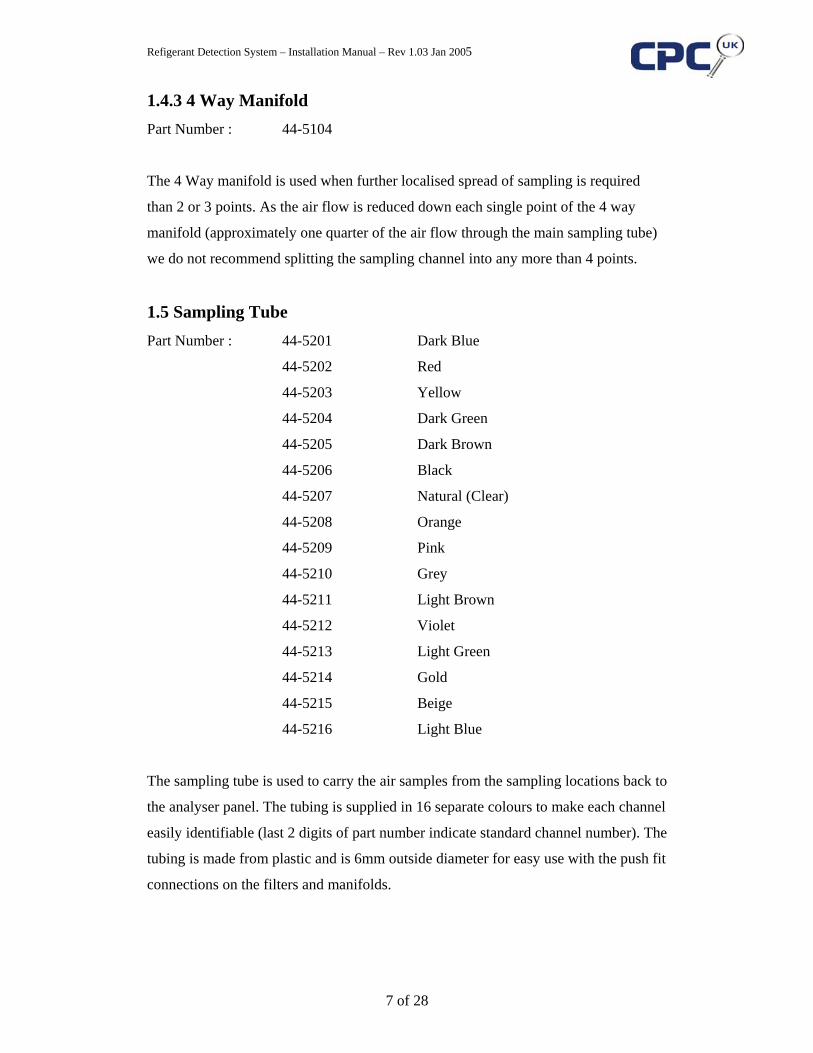
1.4.3 4 Way Manifold
Part Number : 44-5104
The 4 Way manifold is used when further localised spread of sampling is required
than 2 or 3 points. As the air flow is reduced down each single point of the 4 way
manifold (approximately one quarter of the air flow through the main sampling tube)
we do not recommend splitting the sampling channel into any more than 4 points.
1.5 Sampling Tube Part Number : 44-5201 Dark Blue
44-5202 Red
44-5203 Yellow
44-5204 Dark Green
44-5205 Dark Brown
44-5206 Black
44-5207 Natural (Clear)
44-5208 Orange
44-5209 Pink
44-5210 Grey
44-5211 Light Brown
44-5212 Violet
44-5213 Light Green
44-5214 Gold
44-5215 Beige
44-5216 Light Blue
The sampling tube is used to carry the air samples from the sampling locations back to
the analyser panel. The tubing is supplied in 16 separate colours to make each channel
easily identifiable (last 2 digits of part number indicate standard channel number). The
tubing is made from plastic and is 6mm outside diameter for easy use with the push fit
connections on the filters and manifolds.


Refigerant Detection System – Installation Manual – Rev 1.03 Jan 2005
9 of 28
1.6 Other Fittings
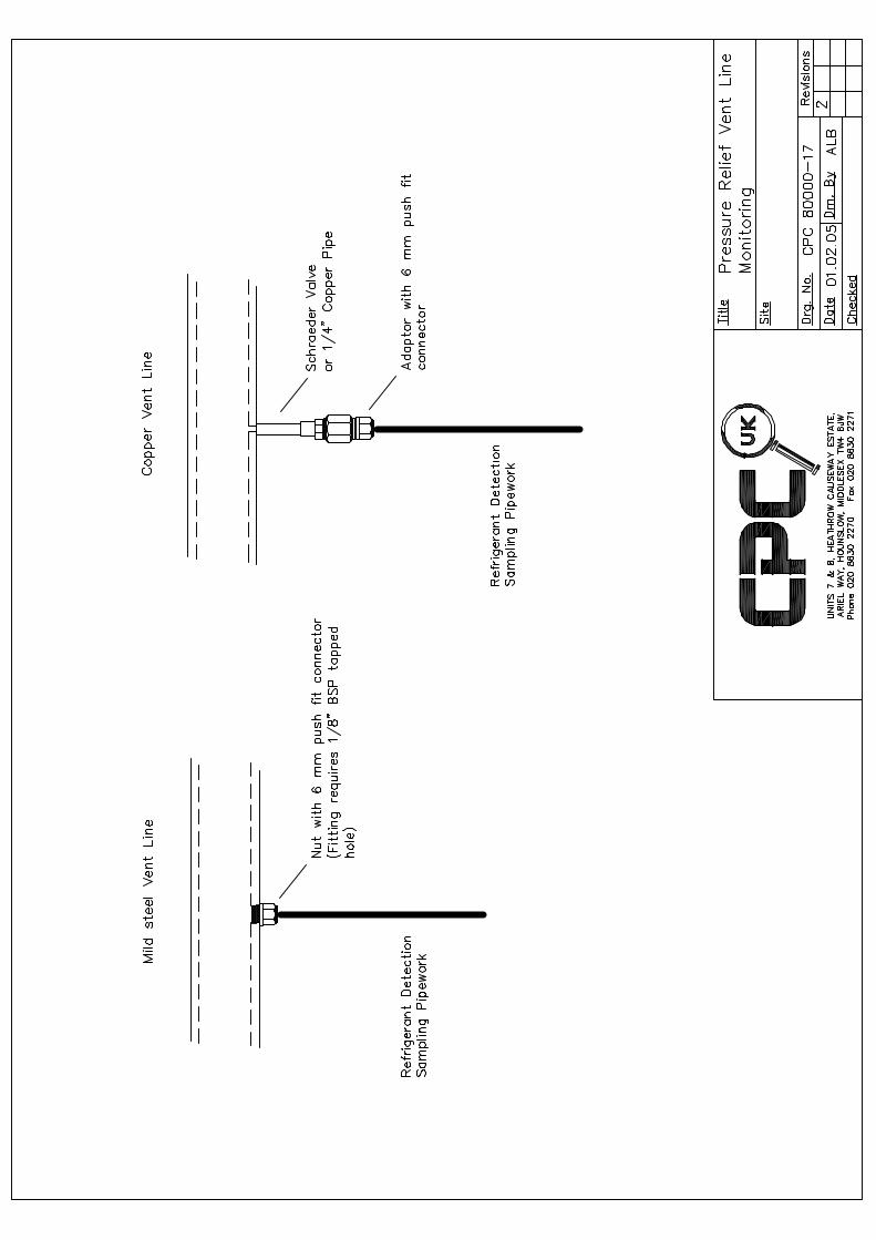
1.6.1 Vent Line Fitting Part number : 44-5100-3
The vent line fitting is used for terminating sampling tube into a steel vent pipe. The
pipe will need to be drilled and tapped to receive the threaded end of the fitting and
the 6mm push fit collar at the other end will receive the sampling tube. Full details for
terminating sampling tube into vent pipes including copper materials are explained
further on.
1.6.2 Straight Connector Part number : 44-5101
The straight connector is used for joining 6mm tube to 6mm tube. It can be used for
joining plastic tube with copper tube when required or simply to repair damaged tube.
1.6.3 Filter Bracket Part number : 44-5111
The filter bracket is used to neatly clip the end of line filters firmly at the required
sampling location. The bracket is screwed to the framework, wall, ceiling, etc. and a
spring clip holds the filter in place.
1.6.4 Warning Beacon Part number : 44-309-5922 Red
44-312-5376 Blue
The warning beacons are used together with the coldroom refrigerant leak alarm
panels to provide local warning to personnel of refrigerant leaks.

Refigerant Detection System – Installation Manual – Rev 1.03 Jan 2005
10 of 28
1.6.5 Lampshade Collector Part number : 45-1000
The Lampshade Collectors are used when the gas being monitored is lighter than air
such as ammonia. The collector allows the end of line filter to be fitted at a lower
level if the ceiling is high making installation and maintenance easier without fear of
missing gas leaks.


Refigerant Detection System – Installation Manual – Rev 1.03 Jan 2005
12 of 28
SECTION 2 : CHOOSING PANEL POSITIONS
2.1 IRLDS Analyser Panel Location
The main points to think about when choosing the analyser position are as follows:-
1) Keep the majority of sampling tubes to the minimum length
2) Easy access for power and communications wiring
3) Accessibility for viewing and acknowledging alarms
4) Possibility of damage
5) Operational noise
Although the sampling tubes can be run in excess of 150 metres for a single channel it
is advisable to keep lengths to a minimum to ensure low pressure drops, good air flow
and minimum sampling and cycle times during sequential sampling. As there are up
to 16 sampling tubes connected to an analyser panel it is best to position the panel
central to the majority of the sampling locations being monitored. The analyser panel
will require mains power to operate and thought must be given to accessibility for
electrical services and communications network wiring to the panel position. The
panel will need to be manually reset in case of alarm and thought must be given to
accessibility to the panel for site personnel. In some cases the panel may be mounted
so that site personnel can view alarms prior to entering a room containing harmful
gases. Analyser panels employed to monitor for ammonia and explosive gases should
be mounted in areas with no possibility of the gas being leaked into. The panel should
be mounted with the display at eye level so that personnel do not have to bend low or
climb ladders when viewing data or alarms. Thought should also be given to the
possibility of damage to the panel if mounted in busy corridors, etc. If the panel must
be mounted in busy areas it is advisable to place protection such as a key clamp to
prevent accidental damage. The final consideration should be given to the operational
noise of the panel; it is not advisable to mount the panel in quiet office areas where
the background noise of the pump in the panel may cause disturbance to site
personnel.


Refigerant Detection System – Installation Manual – Rev 1.03 Jan 2005
14 of 28
2.2 Coldroom Refrigerant Leak Alarm Panel Location
The coldroom refrigerant leak alarm panel, as it’s name suggests, was predominately
designed to initiate warning beacons over the door to individual walk in freezers and
coldrooms in the event of a refrigerant leak being detected in that particular coldroom.
It is therefore advisable to mount the panel in close proximity to the coldroom areas in
order to minimise the cable lengths to the individual beacons for ease of installation.
As with the analyser panel, thought should be given for access to the panel for power
and communications network wiring. The panel is fitted with a buzzer and has a mute
button on the door; therefore the panel should be mounted within easy reach for site
personnel to press the mute button when required.

Refigerant Detection System – Installation Manual – Rev 1.03 Jan 2005
15 of 28
SECTION 3 : CHOOSING END OF LINE POSITIONS
The main points to think about when choosing end of line sampling positions are as
follows:-
1) Most likely points of leakage
2) Areas containing highest gas volumes
3) Protection of personnel
4) Density of gas being monitored
5) Air flow around sampling location and possible collection point
Obviously, the main areas for placing gas detection are the points with the highest
possibility of leakage. Mechanical parts such as valves and compressors and parts
undergoing compression and expansion through pressure or heat have a greater
tendency to leak. Areas containing the largest gas volumes in a system should also be
given high consideration as these have the potential to leak the highest volume.
Working areas with personnel operating within may need consideration in order to
prevent the possibility of toxic fumes causing any harm.
The positioning of the end of line filters within the sampling location is important as
an incorrectly placed filter may cause delay in sensing a leak or may cause the
analyser panel to draw back unwanted substances. The density of the gas being
monitored is an important factor in choosing filter positions; heavier than air gases
will obviously fall towards the floor whilst lighter than air gases will rise towards the
ceiling. Extract fans and louvres will tend to draw the air from a room and
consideration should be given to which way the air may be flowing across the
particular point being monitored to ensure that the leaking gas is pulled towards the
filter rather than away from it. A final consideration should be given to the possibility
of liquids and other unwanted substances being drawn into the sampling lines; end of
line filters should not be placed directly into areas with the possibility of liquid falling
onto them and filters should be fitted at least 50mm above floor level to prevent them
falling into puddles, etc.

Refigerant Detection System – Installation Manual – Rev 1.03 Jan 2005
16 of 28
SECTION 4 : INSTALLATION SCHEDULE
Most CPC detection systems will be supplied together with an installation schedule.
The unit number at the top left hand side of the schedule differentiates between
analyser panels in the event of more than one panel being used on a single site. Other
information at the top of the sheet includes the CPC customer name, contract (quote)
number, the date that the schedule was written and the site name where the equipment
is being installed.
The table on the schedule has 7 labelled columns giving information as follows:-
1) Channel Reference – this indicates the channel number that the sampling
point will be connected to on the analyser panel.
2) Location – this indicates the area or zone to be monitored from.
3) No. of points – this indicates whether a 2 way, 3 way or 4 way manifold is
required. 1 point indicates that no manifold is required.
4) Distance Run – this indicates the length in metres of the main tube run
between the analyser panel and the sampling location.
5) Distance Legs – this indicates the length in metres of each single leg
between the manifold and the end of line filter. Generally this is less than 5
metres.
6) Tube Colour – this indicates which colour tube is assigned to each
particular sampling location. The last 2 digits of the part number printed on
each tube indicate the channel number that the tube is generally used for
(ie. dark blue tube is channel 1, etc.).
7) Comments – this is for any special relevant information that may be
required to assist the installation engineer.
Care should be taken to follow the details on the installation schedule as closely as
possible as in many instances sampling tubes are measured and cut to exact lengths.
Any changes made at site may result in tubes being too short resulting in connectors
and additional tube needing to be supplied.

Uni
t 1In
stal
latio
n Sc
hedu
leC
usto
mer
:C
usto
mer
Engi
neer
s N
ame
:-Q
uote
Ref
:DP
Con
trac
t Num
ber
Dat
e:-
27/0
4/04
Dat
e :-
Site
:-Si
te N
ame
Cha
n.Lo
catio
nN
o O
f D
ista
nce
Tube
Com
men
tsR
ef.
Poin
tsR
unLe
gsC
olou
r
1C
ompr
esso
r Pac
k 1
425
3D
ark
Blu
e
2C
ompr
esso
r Pac
k 2
425
3R
ed
3C
ompr
esso
r Pac
k 3
430
3Y
ello
w
4C
ompr
esso
r Pac
k 4
430
3D
ark
Gre
en
5C
oldr
oom
12
403
Dar
k B
row
n
6C
oldr
oom
22
403
Bla
ck
7C
oldr
oom
33
305
Nat
ural
8C
oldr
oom
43
305
Ora
nge
9M
ain
Ref
riger
atio
n R
iser
240
2P
ink
10S
ales
floor
Are
a 1
175
Gre
y
11S
ales
floor
Are
a 2
175
Ligh
t Bro
wn
12S
ales
floor
Are
a 3
110
0V
iole
t
13S
ales
floor
Are
a 4
110
0Li
ght G
reen
14A
ir H
andl
ing
Uni
t2
502
Gol
d
15C
onde
nser
12
502
Bei
ge
16C
onde
nser
22
502
Ligh
t Blu
e
27/0
4/20
041
of 1

Refigerant Detection System – Installation Manual – Rev 1.03 Jan 2005
18 of 28
SECTION 5 : INSTALLING SAMPLING TUBE
5.1 Main Tube Run
The main considerations when installing the 6mm sampling tube are to keep it tidy,
inconspicuous and not to squash or kink it. The tube can be ran on cable tray,
pipework, steel beams or in trunking or conduit and appropriate fixings should be
used such as cable tie wraps, insulation tape, pipe clips or purling clips. The main tube
runs should be fixed approximately every 1.5 metres to prevent them sagging or
working loose, however, care should be taken not to over tighten any fixings which
may result in crushed or damaged sampling tubes. Tight bends should also be avoided
as this will probably cause the tubing to kink and give flow fault alarms when the
analyser panel is switched on; large radius curves should be used when the tube run
needs to change direction. Main tube runs should be taped at each end until the final
filters are fitted to prevent dirt getting into them.
Thought should be given to ensure that the tube is not installed in areas that may
cause long term damage to it or be a nuisance to maintenance contractors. Tubes run
along hot pipes or close to moving parts run the risk of being melted or worn and
tubes fixed to mechanical parts such as compressors may impede maintenance work.
5.2 Manifolding
The main sampling tube run will connect the analyser panel to the required sampling
location. If the sampling location does not require a localised spread of sampling then
a single end of line filter will be fitted at the sampling location end of the tube. The
sampling tube should have a neat cross sectional cut at the end to ensure a good
connection when fitting the push fit end of line filter. Where a further spread of
sampling is required such as a large multi-compressor pack having several points
fitted underneath the compressors either a 2 way, 3way or 4 way manifold will be
fitted. The single exit of the manifold will be fitted to the end of the main sampling
tube run leaving the multiple exits for the sampling legs. Each sampling leg from the
same manifold should be of equal length and should not exceed 5 metres in length in
order to keep identical air flows through each leg and pressure drops to a minimum.


Refigerant Detection System – Installation Manual – Rev 1.03 Jan 2005
20 of 28
5.3 Packs and Coldrooms
Sampling locations such as compressor packs, receivers, header stations or condensers
generally have steel framework surrounding the main components. It is advisable to
fix the sample tube and sampling legs to the framework and to clip the end of line
filters on the framework supporting the major components.
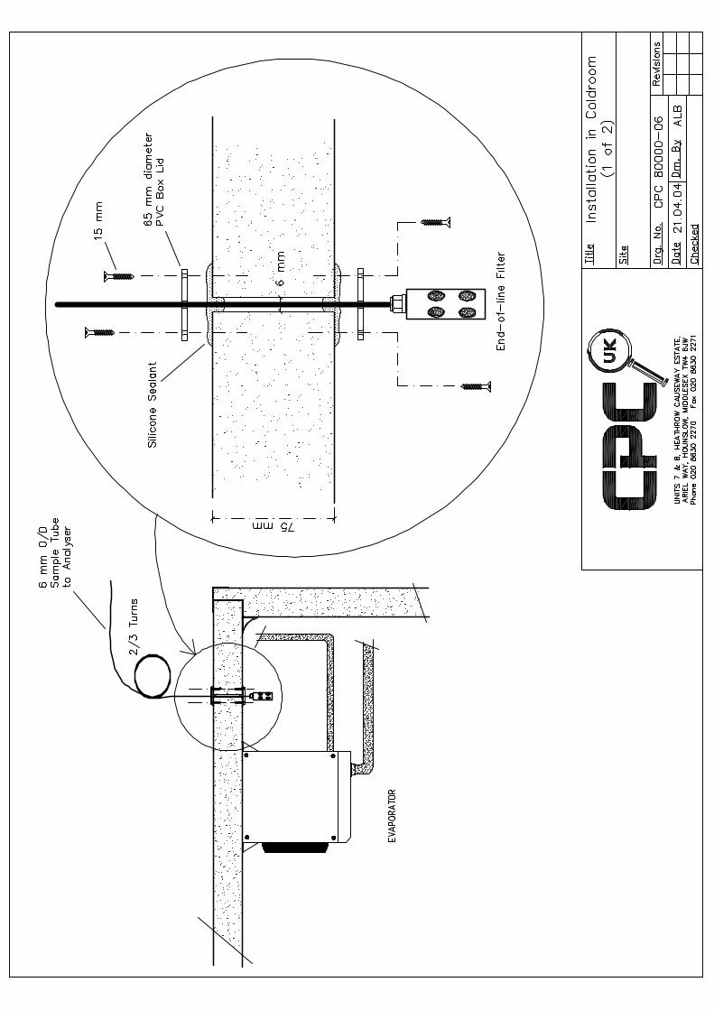
Sample tubes being fitted to coldrooms should be kept to minimum lengths inside the
coldrooms to prevent them freezing up. It is recommended that a sampling point is
fitted behind each evaporator just below the ceiling (heavier than air gases will rely on
the agitation of the air within the room by the evaporator fan to reach the end of line
filters). The manifold should be fitted to the main tube run outside the coldroom and a
separate leg ran behind each evaporator inside the coldroom. A 6mm hole should be
drilled through the coldroom roof just behind the evaporator and through the middle
of two plastic conduit stop end box lids. The box lids should then be fitted above and
below the hole through the roof, the tube pushed completely through the holes and
sealed with silicone sealant.