reflection of electromagnetic waves from thin ionized … of electromagnetic waves from thin ionized...
TRANSCRIPT
JOURNAL O F RESEARCH of the National Bureau of Standards-D. Radio Propagation Vol. 66D, No. I , Janua ry- February 1962
Reflection of Electromagnetic Waves From Thin Ionized Gaseous Layers
F. H. Northover
Contribution from Department of Mathematics, Carleton University, O ttawa, Canad a
(Received Marc h 24, 1961; r evised August 3, 1961)
The reflection properties of thi n ionized layers are examin ed, a nd earli er work o n t he parabolic layer, which seems unsatisfactory in do me respects, is placed upon a more rigoro us footing. " There the layer extends over most of t he trans mission path, a n a pproximate estimate is made of t he rate of attentuation of t he wav es around t he cur vcd cart h. In t his way it seems possible to account for t he freak lo ng distance trans mission of vcry high frequency radio wave which is sometimes observed: a particu lar example of th is is considered in detail.
1. Introduction
I t is the usual practice in ionospheric analysis to make usc of optical methods of treatment. '%ile
I t his tech!1ique is satisfactory for ionospheric layers whose thIcknesses are great compared with the wave-
• length of the critical p enetration frequency of the , layer , results thu s obtained are likely to be misleading
when this condition does not apply. It is now experimentally es tabli heel th at thin E
a~ld sporadic- E layers are capable of causing long dIstance propagation of HF radio waves through re-
I
flections at oblique incidence. One of the first to investigate these reflections theoretically was Hartree [1929], who considered a layer dis tribution law in which the electron den sity increased linearly and symmetrically from the two edges to a peak: at the middle. A simpler formula for the reflection coefficient for this case was given in an independ ent investigation by Beghian and Northover [1943]1 In 1930 other distribution laws were examined by Epstein [1930] and, later on , the parabolic law was investigated by Rydbeck [1943]. Although the results of these last two writers explain the main features of the reflection phenomena for thick layers, their analysis becomes completely erroneous for thin layers. The error arises through th eir attempts to
I short circuit the four equations expressing th e two boundary conditions at each layer edge by attempting to force a physical interpretation upon what
I after all amounts to nothing more nor less than a theorem of pure mathematics. The consequent erroneous conclusions show up much more clearly in the Rydbeck paper because this is concerned with only one specific case- the parabolic distribution.
I The formula (9) on page 347 of his paper for the reflec ti~n coefficient R gives the absurd resul t th at R-o> 1/.J2 as the layer thickness tends to zero. See
I further , appendix 1. On simple ray theory, reflection from the under-
I side of a sporadic-E layer (thin ionized layer
1 See end of section 3.
609993---'62- 7 73
occurring sporadically) would be almost complete for frequencies below the maximum usable frequency ~MUF) but almost negligible for higher frequencies. Vertical incidence measurements, howevcl', have shown that a certain amount of reflection often occurs at frequencies higher than t he NIUF and, for this reason, it may be difficult to decide t lte exact value of the critical frequency of the layer. As far as is lmo wn Lo t he writer, few systemat ic observations have been made at oblique incidence, but it is eviden t both from theory and practical experience that t his phenomenon may becom e increasingly important for rays incident at high obliquit ies upon t he laye r. In particular, serious modifLcations to the skip distances calculated on ray theory may occur when the layer is thin.
2 . Reflection of Plane Waves 2 .1. Prelimina ry Analysis
If t he layer is horizontally stratified , and the waves horizontally polarized, the components of the electric vector satisfy the two-dimensional wave equation
(1)
where oy is horizontal , OZ is ver tical, the usual exponential t ime factor is assumed, i .e., exp (-iwt) , and
2_47['2p ( 11 ) Ii -----cJ2 1- p +i v.f
.iN being the plasma frequen cy at height z and v being t he collision frequency. Here.f is the wave frequen cy and c the velocity of light and we are neglecting the effects of the ear th's magnetic field .
In t he sporadic-E r egion v can usually be neglected in comparison with .f for .f much greater than a megacycle. H ence, neglecting v/.f, and writing
(2)
so that e is the angle which the incident wave makes with the normal, we have,
(3)
The only type of ionic density distribution which is amenable 2 to rigorous mathematical analysis is the parabolic law investigated by R ydbeck in 1943, which m ay sometimes represent an approximation to the truth . Taking the origin at the center of the layer, this may be expressed as
(4)
where 2 7 is the thickness of the layer, N is the ionic density at any point within it, and N o is the maximum value of N within the layer.
It can be shown that the plasma frequency jN is given by
(5)
where e is the charge on the ion and m is its mass: hence,
(6)
wherejNm is the maximum value ofjN'
By (6) and (3) the equation satisfied by F (z) within the layer is
where
d2F d,),Z+JLNm {(A2-1) + l }F= 0 (7)
z "(=-.
T
2.2. Physical Meaning of A
(7A)
It can be shown from l}) that. if the thickness of the layer is large compared with the wavelength of the radio frequency j an upward traveling wave near the center of the layer has the approximate form
Accordingly, if A< I this wave will be strongly attenuated which m eans that strong reflection has occuredlower down. HencejNm sec e is the oblique penetration frequency when the layer thickness is very large compared with the wavelength of the frequency used, so that A denotes the ratio of the frequency used to the maximum usable frequency for thick layers appropriate to the particular obliquity of incidence under consideration.
When the thickness of the layer is of the order of ANm however, it is found that the transition from
'Because tbe parabolic cylinder functions are relatively well known, c.f. Whittaker and Watson .
reflection to transmlsslOn as A increases through unity is a good deal more gradual and, further , t hat if 27 is much less than 0.2 ANm' reflec tion is slight for all values of A.
2.3. Calculation of the Reflection Coefficent
Let the wave incident upon the layer be repre
sented by exp { 21 z cos e}. If R, R are the
complex reflection and transmission coefficients respectively, then the reflected and transmitted waves are represented by
2".ij -- z coso
R e C ,
respectively.
- 2".i/ z cos 0 R e c (9)
If u \"( ) , v("( ) denote any pair of fundamental solutions of (7), the boundary conditions at th e layer give
-~ TCOS() ~TCOS8 ""\
e C + R e c = Au(-l) + Bv(- l ) I . . He~Tcos8=Au(1)+Bv(1) ~
~:w cos e(e -:TCOS 0 - R e '-'f.T cos O)= Au'( - 1) + B v'(- l ) J ~7W cos e R e '-'fTcoso=Au'(l ) + Bv' (l ).
74
c
(10) where
w= 27rj. (lOA)
Writing 2iw R R - TeOSe (11) 1= e C
and L = u(l)v( - 1) -u( - l )v( l )
JLMI = u' (l )v( - 1) -u( - l )v' (1 ) (12) JLM2 = u(1)v' (- l )-u' (- l )v(l )
JL2N=u' (1)v' (-1) -u' (- l )v' (1) where
JL = 27rT/A (12a) we have
RI (L cos2 e- N) +i(M I + M 2) cos e
(13) (L cos2 e+ N) +i(M 1- J112) cos e
In the most important cases physically the solutions of (7) can be approximated to by the Jeffrey's (W .K .B .) method of asymptotic approximation. This method was afterwards extended by R. E . Langer [1937]. It consists of obtaining an asymptotic solution of the standard equation
(14) in the form
(15) I
It can be shown that (IS) is useful only when both
/Scp' 2/32cp3/ and /cp" /4cp2/ are small ,3 and that a further
refmement of (IS) is
cp- I! 4 exp [ ±ifY {~_ cpl/ /8cp3!2+ ScpI2/32cp5! 2 } d')] (16)
We require only the approximate values of u and v neftI' (.he edges of the layer (-y = ± 1) and then the above conditions of validity for (IS) require that
and !lNmA 2> 2 if A> 1
(17)
2.4. Calculation of u(-y) and vb) at the Loyer Edges
The approximate formulas for u and v near -y = + 1 cannot be used ncar -y = - Ion account of a Stokes phenomenon in the asympto tic solution (IS ) as we pass through the layer . We shall obtain the required continuation of u (-y ) and v(-y) for negative values of-y from the theory of the Weber Parabolic Cylinder Function [Whittaker and Watson, 1927] .
EquaLion (7) can be writLen
where V= -y (2!lN m) 1/ 2 ;
and solutions are
D ±ia-t (ve=F~) and D ±ia-! (_ve=F7}
(18)
(1 8A)
We shall take, for u(-y) and v (1') , the conjugate
But no Stokes line is crossed between 1' = + 1 and . v2 •
-y = + cx) , S111Ce a+4 rrma111R positive. Hence, by
(20 and (22) we have
(23)
This formula is valid near the upper edge ot the layer (-y = 1) subject to the conditions (17) . Now
+ 27r , (ia+!,)i" D ( ~) (24) r (- ia+ t) e - /a- 1 ve .
Hence for 1
-~<arg v< 7r ,
- (i ,,- , ) --5i" ( i") u (- 'Y)= e 4 D ia -1 ve 4
+ , /27r 3i" (ia+1) ( ~) r (- ia+ t ) e 4 D_ f a - l ve 4
= ei,.. (ia- t) U (-y) + ,I"'F 1 e1(ia+ ,)i".V(-Y ) r (-W+ 2)
(2S)
(26)
functions Again, from (23)
(-y real). (19)
The Jeffrey's approximations to (18) are found to be
(20)
Now if v-t CX) and a is fixed, the well known formulas
valid when z is large, n fixed and /arg z/< 37r/4 gives
(22)
, Say less tban )4.
75
the error being of the order of the error incurred in using Jeffery's approximations. Hence, (2S) and (26) give, neglecting error terms of order
(2!lNmA 3)-1
u(l ) (A~) ia (!l;m) va-teti!'NmA (28)
u( - 1) = - i e-,,"a (A + l )ia (!lNm) 1ia-te,!,N miA
.fA 2
.J2; ~+!!>: (A+ l) -ia + e 2 4 • -'---'-=~-r ( - ia+1h) .fA
(29)
l_
Hence L = u (l)u( - 1) - u(1 )u ( - 1)
-the conjugate function
1 (}J.Nrn) - 1/2 . . . =A: 2 e-"a(2~+2ta S1l1 cp)
where
Similarly, we find
(32)
(33)
}J.lvC= .f2j;.cm • 2iae-"a cos cp= - }J.M2 (34,35)
Now
wL= 1 + a sin cp }
wlYf1= a cos 8 cos cp=-wJYf2
wN= cosz 8(asin cp - 1)
where w is a constant factor3 This gives
R 1 . = ----; e'<P
I a~
(36)
(37)
(38)
(39)
This formula is ~rue subject to the conditions (17), so long as 1/a IS large compared with the error
76
incurred in using J effrey's approximations . Using the refinement (16) it is possible to show that
where
Hence, even when }J.Nm is not small, there is a wide divergence from Rydbeck's result 4 when a exceeds about 0.5, and the reflection coefficient actually vanishes for values of A and }J.Nm which make cp near to an odd multiple of ?f 7['.
2.5. Case when }J.Nm is Small- the Series Solutions to (7)
Equation (7) is
dl2~+(A+Hl) Q= 0 G')'
where
(41)
(41a)
and it can be shown that, as far as squares and products of the small quantIties A and B, two fundamental solu tions 5 of this equation are
u (')') -'-- l - ! A')'2_~ B')'4+~ A2')'4 . 2 12 24
7 AB 6 1 B2 8 +360 'Y +672 'Y
( ) --'- 1 A 3 1 B 5+ 1 A2 5 V 'Y --;-1-"6 'Y - 20 'Y 120 'Y
+ 13 AB 7+ 1 B2 9 2520 ')' 1440 'Y
(42)
Using these approximations to evaluate approximately the functions L , M I , M 2 ) and N we find
whence
(44)
• F ormula (9), p. 347 for R . • Kot the U(7) and V(7) in (19) ctc.

provided that }J.Nrn and 2}J.Nrn(A2- 1) are both less than unity. The reflection coefficient therefore becomes small if }J.N1Il < < 1 and tends to unity if }J.Nrn/r > > 1,
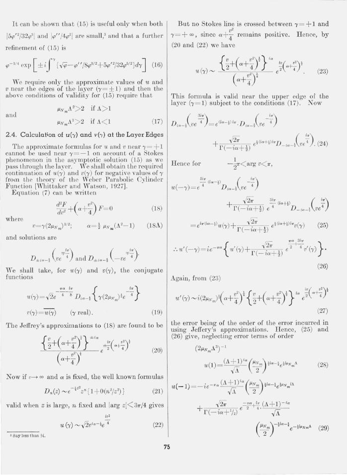
3 . Discussion of Results
The behavior of I R I for the most interesting values of}J.N and A is exhibited in the graph. Now, as }J.N -=:'0, IR I-3>O, and, as }J.N -3>00,
In Tn
IR I-3>1 if A< 1
-3>1//2 if A= 1
-3>0 if A> 1.
Since lE I is contin uous it must, for every fixed A> l, have a maximum value IRIM for some value J.lM (A), say, of }J.,vrn and it can be hown that IE I'1 and J.1.M are steadily decreasing function s of A when A> 1. If we say that IRI>lh for appreciable reflection, we find that the greatest frequen cy for which good reflection can occur (IHI", > 1/3) is given by 1\ = 1.23, approximately, the corresponding value of }J.M then being about 1.33 . Taking as typical the values jNrn= 3Mc/s, h = 80 km, we find that the greatest freq uency which can suffer appreciable reflection (under the above mentioned criterion) is 23 Mc/s/ provided that the layer thickne s is then near 42 m.
When the frequency is near the ray theory MUF (in this case about 19 Mc/s), A= I , and Ill l exceeds }~ only for layer thickne ses greater than 0.16 ANrn.
Thus, for j =3M c/s, good reflection can be obtained at the ray theory MUF for layers down to about 16 m thick.
3.1. Intense Sporadic- E Formation- Bennington's Figures
In the case of the intense sporadic- E ionization described by Bennington [1952], INrn may be expected to be as large as 7 Mc/s for roughly 8 percent of the time during the summer months (c.f., fig. 4 of his paper). It woulcl seem, therefore, to be not unreasonable to take 7 Mc/s as a typical value for fNm
for intense sporadic- E ionization. As the height of this ionization was about 115 km, we now find that the greatest frequency which can suffer appreciable reflection, according to the criteria and theory of the preceding paragraph, is 45 Mc/s, provided that the layer thickness is then near 18 m.
When the frequency is near the ray theory MUF (in this case about 37 Mc/s) , A ~ 1, and lE I exceeds 1/3 for layer thicknesses greater than 0.16 ANm• Thu for fNm= 7 Mc/s good reflection can be obtained at the ray theory MUF for layers down to about 7 m thiclc
' 'l'his corresponds to the ray which strikes the layer at the greatest possible obliQuit.y and i~ determined by elementary geometry of the curved earth.
77
1.0 --...,---..---...,---..--":";";';;' :.:.=::.:::,....::..:..:..:.:..!.~-~
I-2 w
0.8
Q 0 .6 u.. u.. w o u 2 o i= u 'j 0.4 u.. w 0::
0.2
4/3
R.C. BECOMES OSCILLATORY
... 0 AS l\. INCREASES
o '--_-'-__ .1....-_-'-__ '--_ L..._--I-_---l __ "":
0 . 6 0.8 1.0 1.2
l\.
FlOmm 1. R efl ection coefficient versus A.
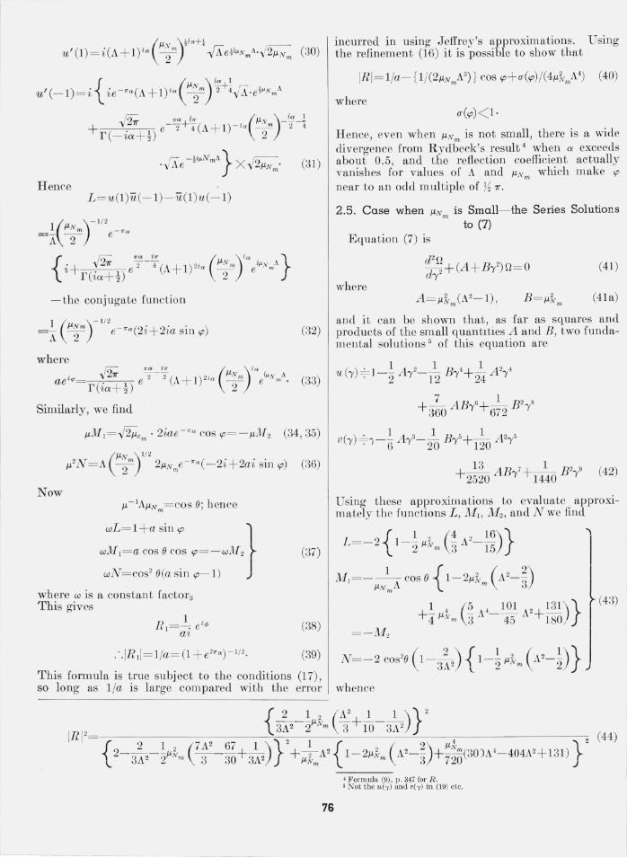
3.2. Note on the Linear Law of Ionic Density Distribution
The writr.r has investigated tbe linear law of distribution
However, as only straightforward mathematical methods are required for what is in this case a straightforward boundary value problem we shall only quote below the result obtained for the reflection coefficient of such a layer. It is
IR I=_-/1 ~X2 where
where
lc= (J I/3 J ":1/3- J i/3 J - 1/3) (J I/3J i/3+ J -1/3.!!.2/3)
+ (J i/3J -2/3- J :2/3J 2/3) (Ji/3 J2/3+J~1/3J -2/3)
I n is written for J nUs }J.NmA3)
J * is written for J { ~}J. (A2_ 1)3/2 } n n 3 Nm .

I-Z W u G: lJ.. W 0 v z Q l-v w ..J lJ.. w II::
( LI NE AR LAW) (LOG SCALE) .5 r------.-------.------,-------,-----~
.4
.3
. 2
. 1
.05 1.388
.04
.03
. 02
.Ol~----~~----~~----~----~~----~ o 2.5
r / AN m FIGURE 2. R eflection coefficient verS1lS 'Tj twm.
4 . Attenuation of the Waves Around a Curved Earth
paper. fig. 2), it might be possible for sporadic- E ionization to develop over much of the transmission path if this lay nearly along a meridian. If the sporadic-E was well developed over the widely separated points necessary for multi-hop transmission (see appendix 2), the field strength over the transmission path would be approximately the same as that which would be due to a thin ionized layer concentric with the earth. vVe therefore proceed to investigate the latter problem and in this way at, tempt to account for the extraordinary reception !
of the BBC's 1949 Oxford-Cambridge Boat Race television transmission in Capetown, and other more recent similar freak transmissions.7
4.1 . Field Beneath a Parabolically Ionized Layer
Let the field be due to a horizontal dipole situated below the layer at height H above the ground. and be emitting waves of frequency j. The effective dielectric constant below and above the layer will be taken as unity, and, within the layer as approximately I - I MP where jJ.- ft-m (1 - 'Y 2) {see (la) and (6) }.
We take spherical polar coordinates (T,O,</» with origin at the earth's center, initial line (0 = 0) along the line joining the earth's center to the transmitter, and the direction of the dipole axis parallel to </> = 11"12 . It can then be shown [Northover, 1952] that the tangential electric field E~ over a perfectly conducting earth (this assumption is a good approximation in most cases of HF propagation), is,
811"2H z (3rl)t~ or -I • { ( .... r '+ }T) , } (45) R'A3/2 Od T '.7" j exp - A //, j x'O
where H, z are the transmitter and receiver heights, R is the earth's radius, }.. the wavelength, 0 the velocity of light, d= RO, r, the radiated power, and I
X" Y j are numbers given by the equation
(46) In most cases of propagation by reflection from where
sporadic-E layers the ionization is confined to the locality above the mid-point of the path. Since, vj= x(1 + EJ) , however, sporadic-E formation tends to be most marked near noon each day (c.f., Bennington's Here
k N { !:v- y, (y) } 2+ L { !:~ _ ~ (y) } 2_ (1111+ 1112) !:v - ~ (y)!;; _y, (y) NTJv _y,(y) !:v-y,(y) + L!:~_)i (yh'-~(y) - 1I11!:v -y,(yh~- ~ (y) - 1I12!:~_~ (y) TJ p-y,(y) (47) I
In deriving (47) from equation \40) of the abovereferenced Northover paper we are taking Yl = y = 211" (R + H )/}.. since the layer thickness is so small in comparison with /its height. The!:, TJ functions are the Hankel-Nielson Bessel functions defined in the above referenced paper.
where y= 211"(R + H){A
and the layer functions L, M I , M 2, N are defined by (12) in terms of functions u('Y) , v('Y ) which satisfy equation (18) in which now
a =~ ,uNm(A 2_ 1), V= 'Y(2,uNm)Y. } and
A= j {2(p- E) }'A./fNm' p= h/R (47A)
7 For example, the occasional reception of BBC television in the U.S.A.
78

In the present applications, X2/3 p is very large (e.g., if h= 80 km and A= 7m, it is about 364) flnd it may then be hown (c.f., the above-referenced paper) that, for t.he dominant terms of (45), Xj+ iYj is small. Hence for these terms
27.f e - i~/4tv _Y2 (Y) "-' (p- f) -7.f exp { - f .f1 ix(p- f)% }
27.f ei7r / 47}v _Y2(Y) "-'(p-f)-7.f exp { f ,12 iX(p-f)%} (48)
and therefore (45) and (47) become,
tv - 11(X) 7} v- Y2 (x)
N - 2(p-f)L+i [2(p - f )]Y2 (M2+ M 1)
N + 2(p - f )L + i { 2(p-f) }Y2(M2 - MI)
exp { -tiX.f1(p-f)%}=-i~
exp { -ti.f1(P - X +iY)~li} (49)
where P = X2/3 p, and ~ is the complex reflection coefficient of a ray incident upon the layer at an obliquity Xl defined by
(50)
Thus
(51)
Finally, .9; is defined by (c.£. the above-referenced pape}')
Unfortunately, the field series (45) does not admit of a straightforward evaluation as no simple formula for .r:;;;; can be found. We must therefore be content with a rather rough discussion. Since P is very large and X j+iYj is small, it is evident from section 7 of the above-referenced paper that the curvilinear attenuation coefficient xtY j of the principal "modes" is approximately
1. e.,
~_ log (l/IRI) nepers/radian (53) 2-y2p
where R is now the complex reflection coefficient at the obliquiLy given by (50).
4.2. Discussion of the BBC Freak Transmission of 1949
In 1949 the television transmission of the Boat Race was pieked up in South Africa. The above theory may be used to provide an explanation of this (and similar infrequent phenomena) on the hypothesis that a thin ionic layer of sporadie E ionization extended over most of the path (or at any rate over
those parts of it near the widely separated points necessary for a multi-hop transmission over this path).
Taking jNm =3 Mc/s. and h= 80 km, we find that A= 2.26 for A= 7 m. For this value of A it can be shown from (44) that ilM= 0.2182 and IR I.M' = 0.0443. Thus, by (53) the smallest possible value of the curvilinear attenuation coefficient is 9.86 nepers/radian, provided that the layer thickness is then near 7 m . Small though this attenuation rate is, it still gives a somewhat large signal loss over thi.s long transmission path. HjNm = 4 Mc/s, we fmd A= 1.7 , ilM= 0.4082, and IR I.M' = 0.1058. The attenuation coefficient is now 7.1 nepers/radian provided that t he layer thickness is now near 10 m. Finally . in the case of the sporadic E layer ionization as intense as that described by Bennington, it will not be unreasonable to t<1Jm 7 Mc/s as a typical value of jem. Here, h = 115 km and we find tbat A= 1.17 for A= 7 m. For this value of A we have ilM about l.5 flnd IR I1I{ = 0.38. The attenuation coefficient oJ the principal modes is now 2.55 nepers/radian provided that the layer tbiclcness is about 21 m.
5. C ritical Appreciation of the Results As has been already pointed out, it is impossible to
discuss the field strength at distflnt points around the earth's curve caused by reflection from a thin elevated ionic byer with any degree of precision, because it is so difficult t.o estimate the values of the amplitude factors :Y;. But even if this were not so, it would stIll be impossible to obtain an elementary expression for the field streng;th since the attenuation coefficients of the terms at the beginning of the field series (45) decrease so slowly that there are many "modes" having nearly the same low attenuatIOn coefficient (53). These modes will therefore be of roughly the same order of smallness, but. their sum will fluctuate as the transmission distance is increased owing to variation with distance of their relative phases. We should, therefore, expect the field strength to exhibit maxima when these modes were most nearly in phase, and these maxima probably occur when the receiver is near those points on the path which can be reached by the smallest munber of transmitter-receiver ray reflections.
When these principal modes reinforce one another, we may reasonably expect that their sum can be approximated to by a single term containing the attenuation hctor (B /2·lip ) log (l/ IRI) given by (53).
For the London-Capetown great· cirele route the angular distance B is very approximately l.49 radians so, according to the above calculations of (53), we should expect the strength of a field strength peak at this distance to compare very unfavorably with the field strength near the limit of "ground wave" ranges when f em is 3Mc/s but quite favorably when jern is 7 Mc/s. The above argument is necessarily lacking in precision, but the conclusion reached can be seen to be problably true from ray theory considerations since we have already found that the greatest values possible for the reflection coefficients of rays which strike the layer at maximum obliquity
79

(these are the ones likely to carry the furthest) are 0.0443 for fNm=3 l\11c/s but 0.38 for fNm=7 Mc/s.
It seems, therefore, that the hypothesis of the existence of suitably intense sporadic-E formations over the transmission path might well account for freak propagation of the kind described above. It must be remembered, however, that the phenomenon can only be expected to occur infrequently as, not only is it necessary for the sporadic-E to be suitably distributed over the transmission path, but it must also be of the right order of thickness and of exceptionally high intensity.
6 . Appendix 1
Relation (25), which is equivalent to eq (7) of Rydbeck's paper, can be written
1 m,- j,,- ( 1) V('Y) = -fi;r e - 2+"4 r -ia+z u('Y)
1 e",- j,,- ( 1) +-e 2 - 4T -ia+- u(-'Y) -fi;r 2
or, say,
(I) = (II) + (III) .
According to this writer, (III) represents the " transmitted" wave, (I) the "original" (up going) wave, and (II) the "reflected" ( downgoing) wave.
The reflection coefficient R is then said to be given by the absolute value of the ratio of the constant part of (II) to that of (I). This gives our formula (39), which is applicable only under certain circumstances. The present writer cannot see the validity of thus forcing a theorem of pure mathematics (which is an abstract system based on abstract axioms) to bear a direct meaning 111 a field of physics (an experimental science): indeed, as noted below, this kind of treatment leads to absurd results. Instead, a careful setting down of the four boundary conditions at the layer edges is required, as in our text, but boundary conditions are not even mentioned in Rydbeck's paper. Epstein (pp. 628, 629 ff. of his paper) likewise tries to interpret the ratio of the constants in a purely mathematical continuation relation obeyed by one of the functions in the layer, as a "reflection coefficient." This would perhaps be alright if the same analytic law for the layer extended to all heights but it does not- it extends only to the layers boundaries. A different differential equation (with d1fferent solutions) is applicable outside these boundaries and so there is no alternative to the proper application of the
80
usual boundary conditions of electromagnetic theory, It is , therefore, likewise impossible for the present writer to have any confidence in Epstein's result.s.
Reverting to Rydbeck's paper, the present theory shows that his formula (9). page 347, for the reflection coefficient is correct only when A2-1 «l / }1Nm (A > 1)8 and then only when }1NmA3 is not smalL (see text comments after equation 39). His formula makes R----'71/.J2 as the layer thickness is made to tend to zero-a conclusion that is patently absurd.
7. Appendix 2. Note on the "Spreading Condition" Appropriate to Curved Earth Propagation
As h as already been mentioned, it is essential that the reflecting sporadic-E ionization should be sufficiently well developed in the regions which surround the reflection points of the rays of m aximum obliquity. The condition for this is similar to the corr esponding condition for good propagatiol1 of meter wave VHF by high level tropospheric inversions [Northover, 1952) but it is more stringent because the sporadic-E layer cannot be treated as a discontinuity. The analysis is rather long and will not be reproduced h ere owing to lack of space. The condition is, that the linear dimensions of the sporadic-E ionization region near the reflection points of the rays of maximum possible obliquity should be large compared with (R5/ 6}..2/3)/hl / 2.
8. References
Beghian, L. K, and F. H . Northover, The reflection properties of sporadic-E layers, Admiralty Signal and Radar Establishment, London, Photostat No. P. 146 (1943).
Bennington, T. W., The propagation of VHF via sporadic =E, " Wireless World," p . 5 (Jan . 1952).
Epstein, P., Reflection of plane waves in an inhomogeneous absorbing medium, Proc. Nat. Acad. Sci. U.S. 16, 627 (1930).
Hartree, D . R ., The propagation of electromagnetic waves in a stratified medium, Proc . Cambridge Phil. Soc. 25, 97 (1929).
Langer, R. E., On the correction formulas and solutions of the wave equation, Phys. Rev. 51, 669 (1937).
Northover, F. H ., The anomalous propagation of radio waves in the 1- 10 metre band, J. Atmospheric and Terrest. Phys. 2, No.2, 106- 129 (1952).
Rydbeck, O. E. H. , The reflection of electromagnetic waves from a parabolic ionised layer, Phil. Mag. 340, 342 (1943).
Whittaker, E. T. and G. N. Watson, Modern analysis, p. 347, Cambridge Univ. Press, 1927.
B Only the second restriction applies when O< A:S:;L
(Paper 66Dl-175)