refinery piping fires
TRANSCRIPT

7/26/2019 Refinery Piping Fires
http://slidepdf.com/reader/full/refinery-piping-fires 1/16
2ND INTERNATIONAL SYMPOSIUM ON
THE MECHANICAL INTEGRITY OF PROCESS PIPING
January 30 - February 1, 1996 Houston, Texas U.S.A.
Refinery Piping Fires Resulting from Variations in Chemical Composition of
Piping Materials
Richard B. Setterlund, P.E.
Metallurgical Consultants, Inc.
P. O. Box 88046
Houston, TX 77288-0046
Abstract
A number of refinery fires in recent years are traceable to variations in the chemical composition of piping
materials. These fires are typically more destructive than those due to other causes and can take place
without warning. Some, but not all, were the result of the inadvertent use of carbon steel in alloy steel
piping systems. Others were the result of alloy welds in carbon steel systems while still others were due
to variations in residual elements leading to anomalous corrosion behavior. Recommendations are given
on areas of refinery units where the greatest need for close control of material composition exists.
Key Terms: Positive Material Identification, Refinery Fires, Piping Systems, Wet H2S service,
Sulfidation, HF Alkylation
Introduction
This paper is directed to failures in petroleum refinery piping systems that have caused serious fires. Many
refinery services involve highly flammable hydrocarbon liquid and gasses under conditions of high pressure
and/or temperature and while hydrocarbons alone are not corrosive, impurities such as sulfur components
or chemical agents added during processing can cause loss of metal which generally occurs in a uniform
manner. The combination of flammable contents and uniform metal wastage suggests the possibility of a
massive release of hydrocarbons due to failure of thinned piping. However, this rarely occurs due to the
combination of knowledge of the corrosiveness of various systems and by closely monitoring the wall
thickness of piping.
Despite these safeguards, a number of "catastrophic-type" failures have occurred in refinery piping because
one or more components had less resistance to corrosion or environmental deterioration than the balanceof the piping system. Five examples are given, all from refinery failures investigated by our firm.
Examples
Example 1
The first example is the failure of a slurry recycle line in a delayed coker unit in Canada in 1984. The line
in question was specified to be NPS 6,1 schedule 40 ASTM A 3352 grade P5 (UNS K41545) seamless

7/26/2019 Refinery Piping Fires
http://slidepdf.com/reader/full/refinery-piping-fires 2/16
pipe having a nominal composition of 5-percent chromium and 1/2-percent molybdenum. The line
contained oil with sulfur compounds and coke particles at a temperature of 705 EF (374 EC) and a
pressure of 240 psig (1.66 MPa).
The fire was traced to the rupture of a 16-in. (406-mm) long section of carbon steel, shown in Figure 1,
that had been welded into the line approximately five years previously. The carbon steel section had athickness of only 0.090 to 0.125 in. (2.3 to 3.2 mm) prior to the failure while the adjacent pipe was
between 0.250 and 0.260 in. (6.4 to 6.6 mm) thick. The thin pipe had split longitudinally showering the
unit with hot oil and causing a fire to spread through the unit resulting in a half dozen additional pipe failures.
Figure 2 is a longitudinal metallographic section of one of the girth welds at the end of the carbon steel
section illustrating the abrupt change in wall thickness between the carbon steel section and the adjacent
5-percent chromium steel pipe and weld.
This failure was followed a number of years later by a similar failure in another coker unit in Louisiana. This
second failure was also due to the inadvertent use of a carbon steel piping component in a 5-percent
chromium, 1/2-percent molybdenum alloy steel line and also resulted in a devastating fire. In this case,however, the carbon steel component was not from a modification but from the original construction
approximately 16 years earlier.
The unit was subjected to a item by item verification of every alloy piping component prior to being placed
back in service. The oil company expected that there would be about one component per each five or six
feet of run but found that there was approximately one component for each foot of piping. Even more
disconcerting was the finding of an approximate 1.5% error rate in the piping components. Many errors
were relatively innocuous such as chemical compositions being slightly off, higher-alloys being used, or
welded pipe in systems calling for seamless, however, at least one deeply-corroded carbon steel
component was detected.
Partly as a result of these findings, the American Petroleum Institute3 has undertaken the establishment of
an industry-wide document on positive material identification (PMI). The document, RP 578,4 is now in
its initial draft and is based on PMI practices currently in use by a number of major oil companies.
Example 2
The second example is of the failure of a recycle hydrogen line in a Gulf Coast hydrocracker unit in 1994.
The failure was in a section of NPS 6 carbon steel pipe that had been welded into a 1-1/4 Cr - 1/2 Mo
(UNS K11597) hydrogen recycle line. The line contained hydrogen at a temperature of 600EF (315
EC)at a hydrogen partial pressure of 2000 psi (13.8 MPa). The total pressure was 2400 psig (16.5 MPa).
Chromium-molybdenum alloy steel is required for this application to prevent high temperature hydrogen
attack as described in API Publication 941.5
Following the fire, a section of pipe was found to be "missing" from the pipe rack. Fragments, such as
shown in Figure 3, were recovered. The fracture surfaces were flat and brittle appearing.

7/26/2019 Refinery Piping Fires
http://slidepdf.com/reader/full/refinery-piping-fires 3/16
The failure was the result of high temperature hydrogen attack. The microstructure near the outside surface
of the pipe in Figure 4 shows hydrogen attack in its initial form. The iron carbides in the pearlite grains are
being reduced by dissolved hydrogen producing methane gas pressure in the grain boundaries producing
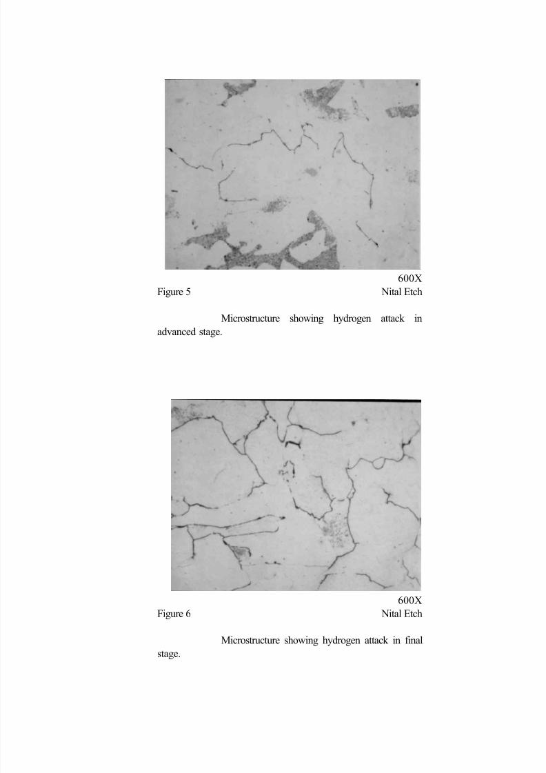
fissures. At the midwall of the pipe, shown in Figure 5, about one-half the carbides had been reduced
producing many cracks. Near the inside nearly all the carbides had been decomposed leaving a network of cracked grain boundaries. See Figure 6.
Investigation revealed that the failed line had been installed twelve years previously during emergency
repairs to the unit following a fire. The line containing hydrogen gas and hydrocarbons was not considered
corrosive and no ultrasonic testing had been done. Over the years the soundness of the carbon steel pipe
deteriorated due to hydrogen attack; increasing the number of internal cracks and pressure from these
cracks added to the pressure inside the pipe produced stresses sufficient to blow the pipe apart. The
explosion and resulting fire from this line had caused failures of other piping in the unit resulting in an intense
fire.
Example 3
In both previous examples, the failures were due to carbon steel components inadvertently installed in
chromium-molybdenum alloy piping systems. This is probably the most common materials error; however,
serious fires can result from the use of chromium-molybdenum filler metal in carbon steel pipe. A recent
fire was due to a welding error in a valve shop during rework of a high pressure carbon steel pressure
letdown valve from a hydrocracker unit. Five percent chromium, one-half percent alloy steel weld filler
metal was used to join carbon steel piping components.
The service conditions for the pressure letdown valve consisted of light hydrocarbons, hydrogen sulfide andmoisture at a temperature of 130EF (54EC) and a pressure of 2714 psig (18.7 MPa). The weld failed
by sulfide-stress cracking (SSC) after approximately 1-1/2 years service. The weld broke open producing
a horizontal V-shaped torch fire pattern which produced secondary flammable liquid fires in downstream
piping and equipment. The failed weld had a chromium content of approximately 4% with approximately
0.5% molybdenum. The weld root had a hardness of HRC 296 and the weld cap had a hardness of HRC
34. The cracking was confined to the hard weld deposit.
Refinery welds for carbon steel in wet H2S service are required to have a maximum hardness of 200 HB7
per NACE RP04728 to prevent SSC. This hardness limit is equivalent to less than HRC 20 on the
Rockwell hardness scale and could have been met without a postweld heat treatment (PWHT) had carbonsteel filler metal been used for the weld. The 5 Cr - 1/2 Mo filler metal that was used is hard in the as-
welded condition and even if its use had been allowed it would have been required to be PWHT by the
refinery piping code.

7/26/2019 Refinery Piping Fires
http://slidepdf.com/reader/full/refinery-piping-fires 4/16
Example 4
The first three examples all were the result of the wrong material being used and could have been prevented
by a PMI program. The final two examples, however, show that similar type fractures can occur due to
compositional differences in material of the same classification.
The failure was in a NPS 4 schedule 80 ASTM A 539 grade B carbon steel line at the outlet of a
hydrodesulfurizer (HDS) charge heater. The line carried heavy naphtha with 0.06 percent sulfur at a
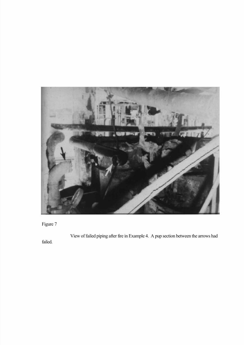
temperature of 610EF (321EC) and a pressure of 450 psig (3.1 MPa). The failure was in a short section
of pipe welded between two 90-degree ells as shown in Figure 7. It was believed that this section had
been added in the field in order to correct an interference problem.
Figure 8 shows the components from the failed line. It was determined that all components other than the
section that failed were silicon-killed carbon steel having between 0.15 and 0.30 percent silicon. The
silicon content of the part that failed was only 0.016 weight percent. Both met the ASTM A 53 grade Bspecification for carbon steel pipe which has no minimum silicon requirement.
The average wall thickness of the piece that failed was only 0.05 in. (1.3 mm) while the five silicon-killed
components had average wall thicknesses of 0.18 to 0.26 in.(4.6 to 6.6 mm) as shown in Figure 9. These
components had been thinned below the minimum wall thickness for new pipe but were above the pipe
retirement thickness shown in the API guide for inspection of refinery equipment then in force.10
Figure 10 shows a longitudinal section of a weld between the failed pipe and adjacent ell.
Field experiences have shown that the silicon content of carbon steel can have a significant effect on therate of sulfidation in hot oil service.11, 12 A failure very similar to that of Example 4 was reported to have
occurred in the feed line to a vacuum heater in a crude unit.13
Example 5
The final example, like the first example given, involved a field splice piece or "pup piece." The pup piece
was believed to have been added in the field to adjust the elevation of the inlet piping to the depropanizer
column in an HF Alkylation Unit. The depropanizer feed line was NPS 3 schedule 80 pipe having an
original nominal wall thickness of 0.216 in. (5.49 mm). It contained mostly C3 to C5 hydrocarbons along
with 0.52 percent HF and a trace of moisture at a temperature of 120E
F (48.9EC).
The 6 in. (15 cm) pup section was thinned to less than 0.05 in. (1.3 mm) wall thickness and failed. Wall
thickness measurements on the balance of the piping showed thicknesses between 0.13 and 0.20 in. (3.3
and 5.1 mm) as shown in Figure 11. The as-received sample is shown in
Figure 12. Note the uniformity of the thinning. Shortly after removal from the line, the failed section had
a rusty color as opposed to the adjacent pipe which retained a metallic color.

7/26/2019 Refinery Piping Fires
http://slidepdf.com/reader/full/refinery-piping-fires 5/16
Chemical analyses of the corroded pup piece and the adjacent pipe showed that both conformed to the
requirements for ASTM A 53 grade B pipe and that the two samples had similar compositions. The failed
section had been deoxidized with aluminum while the adjacent pipe was semi-killed steel. Also, the pup
piece had a somewhat higher level of residual alloying elements.
ASTM A 53Adjacent Pipe Pup Piece grade B
Carbon, % 0.24 0.24 0.30 max.
Manganese, % 0.73 0.99 1.20 max.
Phosphorus, % 0.006 0.007 0.05 max.
Sulfur, % 0.026 0.024 0.06 max.
Silicon, % 0.03 0.04 -
Aluminum, % N.D. 0.02 -
Copper, % 0.01 0.01 -
Nickel, % 0.02 0.09 -Chromium, % 0.02 0.06 -
Molybdenum, % 0.02 0.07 -
(Cu+Ni+Cr), % 0.05 0.16 -
Carbon steel has good resistance to anhydrous hydrogen fluoride (HF) at temperatures up to approximately
160EF (71EC). The corrosion resistance is the result of the formation of a protective iron fluoride scale
that protects the metal from corrosion. The scale restricts the outward diffusion of iron and inward diffusion
of fluoride and the maintenance of an adherent and continuous scale is needed to keep the metal loss at a
minimum. Chromium and silicon which both reduce the rate of corrosion of carbon steel by hot H2S canincrease the rate of corrosion by hot HF.14, 15 Also, chromium, nickel, and copper have all been shown
to be detrimental to the corrosion resistance of steel to hot HF since they affect the formation of the
protective iron fluoride film.16
A recommended maximum combined content of (Cr+Ni+Cu) of 0.2 percent has been proposed for HF
service.17 The failed pup piece met the 0.2 percent combined limit illustrating that composition limits may
not be the proper criterion. The problem was not that the failed section of pipe was "bad" but rather that
it was a short section welded into "better" pipe. Had the piping system been constructed of piping with a
higher impurity level, the loss of wall thickness would have been detected and the piping replaced before
there was a risk of a fire.
Summary
The common factor in the five examples is the unexpected complete failure of a piping component resulting
in a large release of flammable contents. All took place without warning while the units were under normal
operating conditions and, in the five cases presented, the release of hydrocarbon resulted in a major fire.

7/26/2019 Refinery Piping Fires
http://slidepdf.com/reader/full/refinery-piping-fires 6/16
Examples 1 and 2 were cases where carbon steel components were installed in low alloy steel lines. Errors
of this type are now unlikely to occur during new construction since major contractors, as well as most
refiners have strict PMI programs in force. Older units are most likely to contain material errors due to
construction before PMI programs were universally employed and, due to their age, are more likely to have
material errors due to greater amounts of maintenance welding during unit turnarounds, modifications, and
repairs. Individual alloy and carbon steel piping components can easily be segregated by field analyses prior to construction; however, once fabricated and insulated, verification becomes difficult.
The use of incorrect welding materials can also result in serious problems as shown by Example 3. This
can be overcome by quality control procedures during construction followed by PMI of alloy steel welds
to ensure that the correct filler metal is used. Field hardness testing of all welds in wet H2S environments
are recommended to ensure that errors have not produced welds that are susceptible to sulfide-stress
cracking.
Based on Examples 1, 2, and 3 and others mentioned, the following services demand use of a rigorous PMI
program.
1. Hot sulfur-bearing piping systems where chromium-molybdenum or other alloy steels are
needed for sulfidation resistance.
2. Hot hydrogen-bearing piping systems requiring chromium-molybdenum or other alloy
steels to prevent decarburization or fissuring.
3. Piping containing water and sulfide requiring control of hardness and/or stress to prevent
sulfide stress cracking.
The effect of residual elements on corrosion shown by Examples 4 and 5 represent problems that are more
difficult to control. This is due to the fact that residual elements may not be at a high enough level to be
measured by field analyses. Work is continuing on methods to separate silicon-killed steels (>0.1% Si)
from semi-killed steels (<0.1% Si), but at the present time there is no simple and reliable method to do this.
It should be noted, however, that the presence of silicon generally becomes critical only in sulfiding
conditions over approximately 550 EF (288 EC).
Corrosion by hot hydrogen fluoride is another service condition where field analyses are not appropriate
since very small amounts of alloying elements can produce a large change in the corrosion rate. This
problem is now under study by an NACE Task Group.
(18)
In most HF Alkylation units corrosion is not a problem since careful control of the moisture content can keep the corrosion rates of both high and low
impurity steels at very low levels. In those cases where a significant rate of metal loss is found it may be
necessary to make a component-by component check to ensure that the least corrosion resistant
component is located.

7/26/2019 Refinery Piping Fires
http://slidepdf.com/reader/full/refinery-piping-fires 7/16
References
1. NPS 6 refers to six-inch nominal pipe size. This pipe has an outside diameter of 6.625 inches
(168.3 mm).
2. ASTM A 335 "Standard Specification for Seamless Ferritic Alloy-Steel Pipe for High
Temperature," Annual Book of ASTM Standards, Volume 01.01.
3. American Petroleum Institute, 1220 L. Street N.W. Washington, D.C. 20005.
4. API RP 578 "Recommend Practice for Positive Materials Identification (PMI)" (Issue Pending).
5. API Publication 941 "Steels for Hydrogen Service at Elevated Temperature and Pressures in
Petroleum Refineries and Petrochemical Plants," Fourth Edition (1990).
6. Hardness Rockwell C per ASTM E 18 "Rockwell Hardness and Rockwell Superficial Hardness
of Metallic Materials."
7. Hardness Brinell per ASTM E 103 "Rapid Indentation Hardness Testing of Metallic Materials."
8. NACE RP0472 "Methods and Controls to Prevent In-Service Environmental Cracking of Carbon
Steel Weldments in Corrosive Petroleum Refining Environments."
9. ASTM A 53 "Pipe, Steel, Black and Hot-Dipped Zinc Coated, Welded and Seamless."
10. Guide for Inspection of Refinery Equipment, Second Edition (1974), American Petroleum Institute,
Chapter XI pp. 21-24.
11. API Publication 943 "High-Temperature Crude Oil Corrosivity Studies," (1974) p. 23.
12. R. B. Setterlund, "Selecting Process Piping Materials," Hydrocarbon Processing, August 1991, pp.
93-100.
13. R. P. Buhrow, "Know Areas of Vulnerability, Safety Guidelines," Hydrocarbon Processing, August
1986, pp. 19-102.
14. Corrosion Engineering, Fontana and Greene, 2nd Edition (1978) p. 257.
15. G. Trabonellie, et al, Materials Performance, Vol. 24, June (1985) p. 33.
16. T. F. Degnan, "Materials of Construction for Hydrofluoric Acid and Hydrogen Fluoride," Process
Industries Corrosion, NACE (1986) p. 277.
17. H. H. Hashim and W. L. Valerioti, "Effect of Residual copper, Nickel and Chromium on the
Corrosion Resistance of Carbon Steel in Hydrofluoric Acid Alkylation Service," paper 623, Corrosion/93
(1993).
18. NACE Task Group T-8-20, "Materials Considerations for HF Alkylation Units."

7/26/2019 Refinery Piping Fires
http://slidepdf.com/reader/full/refinery-piping-fires 8/16
Figure 1
Drawing showing location of failed carbon steel pup piece in Example 1.
Figure 2
Section through weld showing the difference in wall thickness between carbon
steel pup piece at right and 5% Cr - 1/2% Mo pipe at left.

7/26/2019 Refinery Piping Fires
http://slidepdf.com/reader/full/refinery-piping-fires 9/16
Figure 3
Fractured carbon steel pipe from hydrogen recycle line in Example 2.
600X
Figure 4 Nital Etch
Microstructure showing onset of hydrogen attack.
7/26/2019 Refinery Piping Fires
http://slidepdf.com/reader/full/refinery-piping-fires 10/16
600X
Figure 5 Nital Etch
Microstructure showing hydrogen attack in
advanced stage.
600X
Figure 6 Nital Etch
Microstructure showing hydrogen attack in final
stage.
7/26/2019 Refinery Piping Fires
http://slidepdf.com/reader/full/refinery-piping-fires 11/16
Figure 7
View of failed piping after fire in Example 4. A pup section between the arrows had
failed.

7/26/2019 Refinery Piping Fires
http://slidepdf.com/reader/full/refinery-piping-fires 12/16
Figure 8
Failed sections reassembled in laboratory.

7/26/2019 Refinery Piping Fires
http://slidepdf.com/reader/full/refinery-piping-fires 13/16
Figure 9
Silicon contents and averaged wall thickness measurements of
NPS 4 schedule 80 pipe components.

7/26/2019 Refinery Piping Fires
http://slidepdf.com/reader/full/refinery-piping-fires 14/16
Figure 10
Weld area between failed pup section at right and 90-degree ell at left.

7/26/2019 Refinery Piping Fires
http://slidepdf.com/reader/full/refinery-piping-fires 15/16
Figure 11
Wall thickness readings made after failure of pup piece in HF
Alkylation Depropanizer Column feed line in Example 5.
.20".20"
.20"
SCH 40 ELL
.19"
.19"
.14"
.14"
.14"
.15"
.14"
SCH 40-45
6" PUP PIECE THINNED TO LESS
THAN .05" AND THEN FAILED
.19"
.15"
.15"
.14"
.14"
.15"
.22" MIN
.24" MIN
.14"
.15"
.16"
.15"
.16"
.16"
.16".16"
.19"
.13"
.13"

7/26/2019 Refinery Piping Fires
http://slidepdf.com/reader/full/refinery-piping-fires 16/16
Figure 12
Samples from HF alkylation feed line.
The failed pup piece is at the top and the adjacent pipe at
the bottom.