reference number: tc 8/sc 7/p03/n003/2cdv 1 of 56 committee draft oiml r 137-3 date: 22 may 2013...
TRANSCRIPT

Page 1 of 56
COMMITTEE DRAFT OIML R 137-3
Date: 22 May 2013
Reference number: TC 8/SC 7/P03/N003/2CDV
Supersedes document: TC 8/SC 7/P03/N001/1CD
OIML TC8 / SC7 Circulated to P- and O-members and
liaison international bodies and external
organizations for:
Title: Gas metering discussion at (date and place of
meeting): .............
Secretariat:
The Netherlands
comments by: .....................
vote (P-members only) and
comments by 31 August 2013
TITLE OF THE CD (English):
OIML R 137-3
Gas meters
Part 3: OIML Report format for type evaluation
TITRE DU CD (Français):
OIML R 137-3
Computeurs de gaz
Partie 3: OIML format du rapport d´ exam de type
Original version in: English
Version original en: Anglais
X

Page 2 of 56
Foreword
The International Organization of Legal Metrology (OIML) is a worldwide, intergovernmental organization
whose primary aim is to harmonize the regulations and metrological controls applied by the national
metrological services, or related organizations, of its Member States. The main categories of OIML
publications are:
International Recommendations (OIML R), which are model regulations that establish the
metrological characteristics required of certain measuring instruments and which specify methods
and equipment for checking their conformity. OIML Member States shall implement these
Recommendations to the greatest possible extent;
International Documents (OIML D), which are informative in nature and which are intended to
harmonize and improve work in the field of legal metrology;
International Guides (OIML G), which are also informative in nature and which are intended to
give guidelines for the application of certain requirements to legal metrology; and
International Basic Publications (OIML B), which define the operating rules of the various OIML
structures and systems.
OIML Draft Recommendations, Documents and Guides are developed by Project Groups linked to Technical
Committees or Subcommittees which comprise representatives from the Member States. Certain
international and regional institutions also participate on a consultation basis. Cooperative agreements have
been established between the OIML and certain institutions, such as ISO and the IEC, with the objective of
avoiding contradictory requirements. Consequently, manufacturers and users of measuring instruments, test
laboratories, etc. may simultaneously apply OIML publications and those of other institutions.
International Recommendations, Documents, Guides and Basic Publications are published in English (E) and
translated into French (F) and are subject to periodic revision.
Additionally, the OIML publishes or participates in the publication of Vocabularies (OIML V) and
periodically commissions legal metrology experts to write Expert Reports (OIML E). Expert Reports are
intended to provide information and advice, and are written solely from the viewpoint of their author,
without the involvement of a Technical Committee or Subcommittee, nor that of the CIML. Thus, they do
not necessarily represent the views of the OIML.
This publication - referenced OIML R 137-3, Edition 2013 - was developed by the Technical Subcommittee
TC 8/SC 7 Gas meters. It was approved for final publication by the International Committee of Legal
Metrology in 201x and will be submitted to the International Conference of Legal Metrology in 2016 for
formal sanction.
OIML Publications may be downloaded from the OIML web site in the form of PDF files. Additional
information on OIML Publications may be obtained from the Organization’s headquarters:
Bureau International de Métrologie Légale
11, rue Turgot - 75009 Paris - France
Telephone: 33 (0)1 48 78 12 82
Fax: 33 (0)1 42 82 17 27
E-mail: [email protected]
Internet: www.oiml.org
Page 3 of 56
PART 3: Report format for type evaluation
1 Introduction
This Report Format applies to any kind of gas measuring instruments (gas meters) independent of its
technology. It presents a standardized format for the results of the various tests and examinations, described
in Part 2 of OIML R 137-1 & -2 (2012), to which a type of a gas meter shall be submitted with a view to its
approval based on this OIML Recommendation.
It is recommended that all metrology services or laboratories evaluating and/or testing types of gas meters
according to OIML R 137-1& -2:2012, or to national or regional regulations based on this Recommendation,
use this report format directly, or after translation into a language different from English or French. In case
this Recommendation needs to be translated, it is highly recommended to leave the structure and the
numbering of the clauses unchanged, thus facilitating the interpretation of most of the contents even for
those readers that are not able to easily interpret the applied language..
The Report Format, in the practical application, shall as a minimum contain the clauses A–F (where
applicable) in addition to a cover page issued by the Issuing Authority,
2 Applicability of this Report Format
In the framework of the OIML Certificate System for Measuring Instruments, and the OIML Mutual
Acceptance Arrangement (MAA) applicable to gas meters in conformity with OIML R 137-1& -2:2012, the
use of this report format in French and/or in English is mandatory, including its translation into the national
languages of the countries issuing such certificates, where appropriate.
Concerning the implementation of OIML Recommendation R 137-1&-2 :2012 in national regulations this
Report Format is informative .

Page 4 of 56
3 Guidance for the application of this Test Report Format
Key to the symbols and expressions used in the following pages:
The “summary of the results” and the “results of the tests” shall be completed in agreement with the
following examples:
Class 0.5 Class 1 Class 1.5 No Meaning
Passed for X passed for class 0.5
Passed for X X passed for class 1 and 1.5
Passed for X failed for all classes
Passed for / / / / test is not applicable for this instrument
Unless prescribed otherwise, “Date” in the test report refers to the date of testing.
The name(s) or symbol(s) of the unit(s) used to express the test results shall be specified where
applied.
Where in a table one or several choices can be made, checkboxes are applied. In such case the
columns Y, N, N/A generally are not applicable and thus presented crosshatched (see the example
below)
Clause Description Yes
No
No
t a
pp
lica
ble
Observations
In case a prescribed test is not relevant for the type of instrument to be tested, the reason why the test is
omitted shall be clearly stated in the field “Observations” (for instance tests related to AC mains supply
in case of an instrument only powered by batteries, or partial testing after modification of a previously
approved type).
The numbering of the report and the page numbers shall be completed in the heading.
Pages 1 - 5 of this Report Format are to be replaced by a cover page issued by the Issuing Authority
4 The Evaluation Report
The following pages concern the format for the individual Report starting with space for the cover page.

Page 5 of 56
<Cover page
issued by the
Issuing Authority>
Report number ................... OIML R 137-3 Report page ... of ...
Page 6 of 56
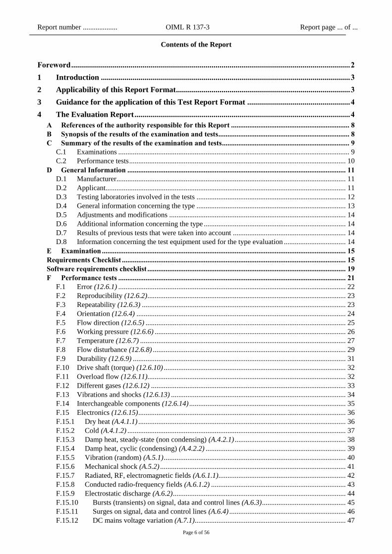
Contents of the Report
Foreword ............................................................................................................................................. 2
1 Introduction .............................................................................................................................. 3
2 Applicability of this Report Format ........................................................................................ 3
3 Guidance for the application of this Test Report Format .................................................... 4
4 The Evaluation Report ............................................................................................................. 4
A References of the authority responsible for this Report ................................................................. 8 B Synopsis of the results of the examination and tests ........................................................................ 8 C Summary of the results of the examination and tests ...................................................................... 9
C.1 Examinations ............................................................................................................................... 9 C.2 Performance tests ....................................................................................................................... 10
D General Information ........................................................................................................................ 11 D.1 Manufacturer .............................................................................................................................. 11 D.2 Applicant.................................................................................................................................... 11 D.3 Testing laboratories involved in the tests .................................................................................. 12 D.4 General information concerning the type .................................................................................. 13 D.5 Adjustments and modifications ................................................................................................. 14 D.6 Additional information concerning the type .............................................................................. 14 D.7 Results of previous tests that were taken into account .............................................................. 14 D.8 Information concerning the test equipment used for the type evaluation .................................. 14
E Examination ...................................................................................................................................... 15 Requirements Checklist ........................................................................................................................... 15 Software requirements checklist ............................................................................................................. 19 F Performance tests ............................................................................................................................. 21
F.1 Error (12.6.1) ............................................................................................................................. 22 F.2 Reproducibility (12.6.2) ............................................................................................................. 23 F.3 Repeatability (12.6.3) ................................................................................................................ 23 F.4 Orientation (12.6.4) ................................................................................................................... 24 F.5 Flow direction (12.6.5) .............................................................................................................. 25 F.6 Working pressure (12.6.6) ......................................................................................................... 26 F.7 Temperature (12.6.7) ................................................................................................................. 27 F.8 Flow disturbance (12.6.8) .......................................................................................................... 29 F.9 Durability (12.6.9) ..................................................................................................................... 31 F.10 Drive shaft (torque) (12.6.10) .................................................................................................... 32 F.11 Overload flow (12.6.11)............................................................................................................. 32 F.12 Different gases (12.6.12) ........................................................................................................... 33 F.13 Vibrations and shocks (12.6.13) ................................................................................................ 34 F.14 Interchangeable components (12.6.14) ...................................................................................... 35 F.15 Electronics (12.6.15) .................................................................................................................. 36 F.15.1 Dry heat (A.4.1.1) .................................................................................................................. 36 F.15.2 Cold (A.4.1.2) ........................................................................................................................ 37 F.15.3 Damp heat, steady-state (non condensing) (A.4.2.1) ............................................................. 38 F.15.4 Damp heat, cyclic (condensing) (A.4.2.2) ............................................................................. 39 F.15.5 Vibration (random) (A.5.1) .................................................................................................... 40 F.15.6 Mechanical shock (A.5.2) ...................................................................................................... 41 F.15.7 Radiated, RF, electromagnetic fields (A.6.1.1) ...................................................................... 42 F.15.8 Conducted radio-frequency fields (A.6.1.2) .......................................................................... 43 F.15.9 Electrostatic discharge (A.6.2) ............................................................................................... 44 F.15.10 Bursts (transients) on signal, data and control lines (A.6.3) .............................................. 45 F.15.11 Surges on signal, data and control lines (A.6.4) ................................................................ 46 F.15.12 DC mains voltage variation (A.7.1) ................................................................................... 47

Report number ................... OIML R 137-3 Report page ... of ...
Page 7 of 56
F.15.13 AC mains voltage variation (A.7.2) ................................................................................... 48 F.15.14 AC mains voltage dips and short interruptions (A.7.3) ..................................................... 49 F.15.15 Voltage dips, short interruptions and voltage variations on DC mains power (A.7.4) ...... 50 F.15.16 Bursts (transients) on AC and DC mains (A.7.5) .............................................................. 52 F.15.17 Surges on AC and DC mains (A.7.6) ................................................................................ 53 F.15.18 Ripple on DC mains power (A.7.7) ................................................................................... 54 F.15.19 Low voltage of internal battery (not connected to the mains power) (A.8) ....................... 55 F.16 Influences from ancillary devices (12.6.16) .............................................................................. 56
Report number ................... OIML R 137-3 Report page ... of ...
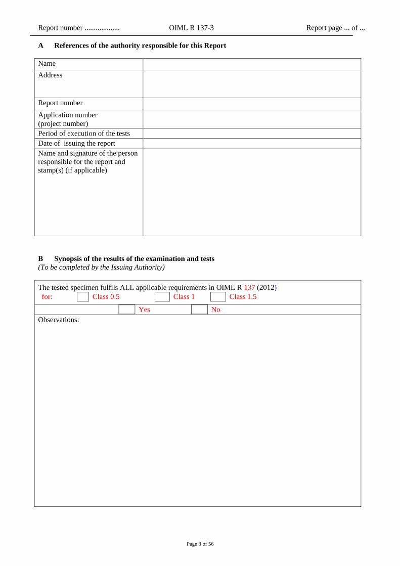
Page 8 of 56
A References of the authority responsible for this Report
Name
Address
Report number
Application number
(project number)
Period of execution of the tests
Date of issuing the report
Name and signature of the person
responsible for the report and
stamp(s) (if applicable)
B Synopsis of the results of the examination and tests
(To be completed by the Issuing Authority)
The tested specimen fulfils ALL applicable requirements in OIML R 137 (2012)
for: Class 0.5 Class 1 Class 1.5
Yes No
Observations:
Report number ................... OIML R 137-3 Report page ... of ...
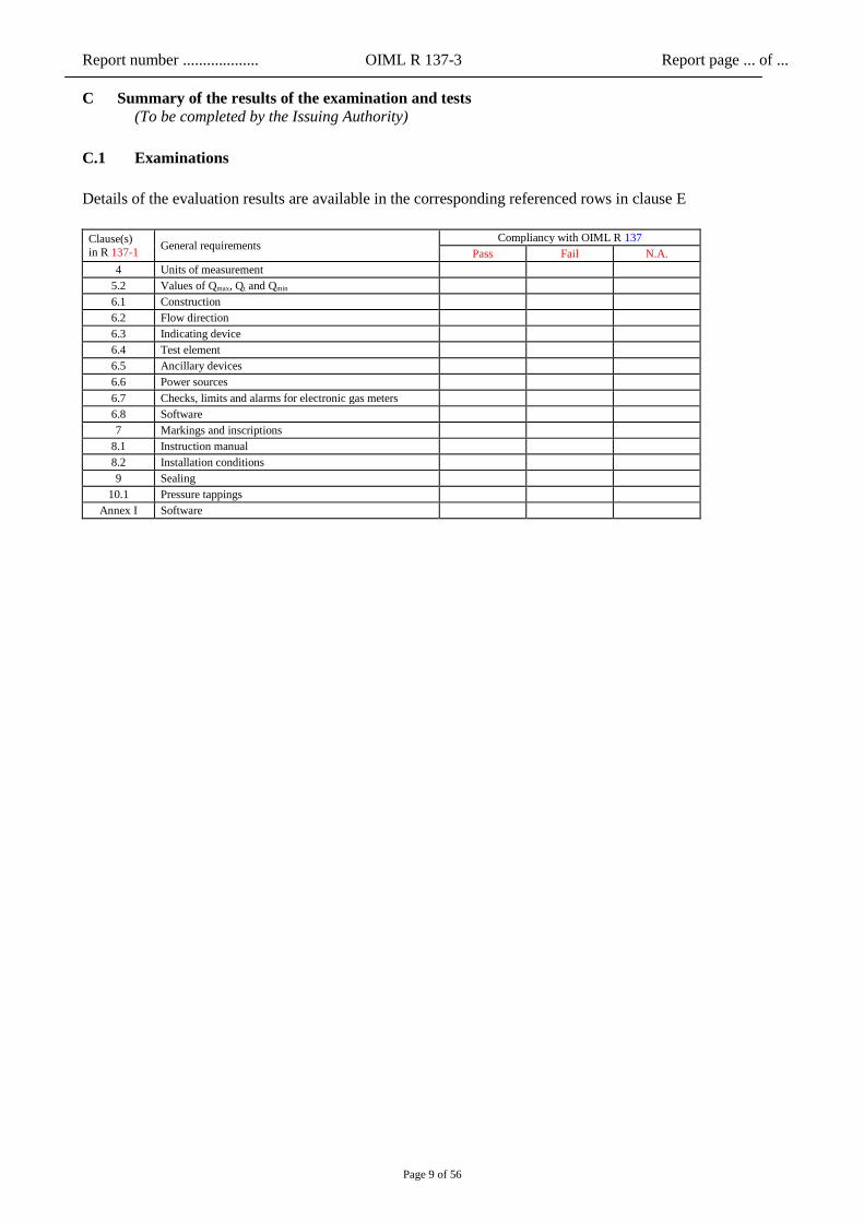
Page 9 of 56
C Summary of the results of the examination and tests
(To be completed by the Issuing Authority)
C.1 Examinations
Details of the evaluation results are available in the corresponding referenced rows in clause E
Clause(s)
in R 137-1 General requirements
Compliancy with OIML R 137
Pass Fail N.A.
4 Units of measurement
5.2 Values of Qmax, Qt and Qmin
6.1 Construction
6.2 Flow direction
6.3 Indicating device
6.4 Test element
6.5 Ancillary devices
6.6 Power sources
6.7 Checks, limits and alarms for electronic gas meters
6.8 Software
7 Markings and inscriptions
8.1 Instruction manual
8.2 Installation conditions
9 Sealing
10.1 Pressure tappings
Annex I Software
Report number ................... OIML R 137-3 Report page ... of ...
Page 10 of 56
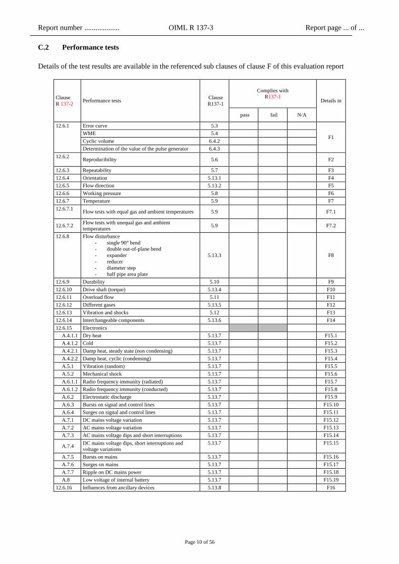
C.2 Performance tests
Details of the test results are available in the referenced sub clauses of clause F of this evaluation report
Clause
R 137-2 Performance tests
Clause
R137-1
Complies with R137-1
Details in
pass fail N/A
12.6.1 Error curve 5.3
F1 WME 5.4
Cyclic volume 6.4.2
Determination of the value of the pulse generator 6.4.3
12.6.2
Reproducibility 5.6
F2
12.6.3 Repeatability 5.7 F3
12.6.4 Orientation 5.13.1 F4
12.6.5 Flow direction 5.13.2 F5
12.6.6 Working pressure 5.8 F6
12.6.7 Temperature 5.9 F7
12.6.7.1
Flow tests with equal gas and ambient temperatures 5.9
F7.1
12.6.7.2 Flow tests with unequal gas and ambient temperatures
5.9
F7.2
12.6.8 Flow disturbance
- single 90° bend
- double out-of-plane bend
- expander
- reducer
- diameter step
- half pipe area plate
5.13.3
F8
12.6.9 Durability 5.10 F9
12.6.10 Drive shaft (torque) 5.13.4 F10
12.6.11 Overload flow 5.11 F11
12.6.12 Different gases 5.13.5 F12
12.6.13 Vibration and shocks 5.12 F13
12.6.14 Interchangeable components 5.13.6 F14
12.6.15 Electronics
A.4.1.1 Dry heat 5.13.7 F15.1
A.4.1.2 Cold 5.13.7 F15.2
A.4.2.1 Damp heat, steady state (non condensing) 5.13.7 F15.3
A.4.2.2 Damp heat, cyclic (condensing) 5.13.7 F15.4
A.5.1 Vibration (random) 5.13.7 F15.5
A.5.2 Mechanical shock 5.13.7 F15.6
A.6.1.1 Radio frequency immunity (radiated) 5.13.7 F15.7
A.6.1.2 Radio frequency immunity (conducted) 5.13.7 F15.8
A.6.2 Electrostatic discharge 5.13.7 F15.9
A.6.3 Bursts on signal and control lines 5.13.7 F15.10
A.6.4 Surges on signal and control lines 5.13.7 F15.11
A.7.1 DC mains voltage variation 5.13.7 F15.12
A.7.2 AC mains voltage variation 5.13.7 F15.13
A.7.3 AC mains voltage dips and short interruptions 5.13.7 F15.14
A.7.4 DC mains voltage dips, short interruptions and voltage variations
5.13.7
F15.15
A.7.5 Bursts on mains 5.13.7 F15.16
A.7.6 Surges on mains 5.13.7 F15.17
A.7.7 Ripple on DC mains power 5.13.7 F15.18
A.8 Low voltage of internal battery 5.13.7 F15.19
12.6.16 Influences from ancillary devices 5.13.8 F16
Report number ................... OIML R 137-3 Report page ... of ...
Page 11 of 56
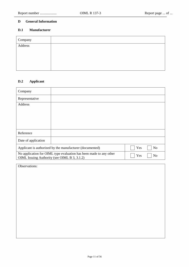
D General Information
D.1 Manufacturer
Company
Address
D.2 Applicant
Company
Representative
Address
Reference
Date of application
Applicant is authorized by the manufacturer (documented) Yes No
No application for OIML type evaluation has been made to any other
OIML Issuing Authority (see OIML B 3, 3.1.2) Yes No
Observations:

Report number ................... OIML R 137-3 Report page ... of ...
Page 12 of 56
D.3 Testing laboratories involved in the tests
(This table to be completed for each test laboratory)
Name
Address
Application number
Tests by this laboratory
Date/period of tests
Name(s) of test engineer(s)
Accredited by Number: Expires (date):
Accreditation includes
OIML R 137 Yes Edition: No
Details of relevant peer
assessment or assessment by
other means
In case tests have been performed
on another location than the
premises of this laboratory, give
details here
Name of the responsible person
Date of signature
Stamp (if applicable) and
signature of the responsible
person
Observations:

Report number ................... OIML R 137-3 Report page ... of ...
Page 13 of 56
D.4 General information concerning the type
and the specimen(s) supplied for the tests
(as stated on the instrument / provided by the manufacturer)
Information, indicated on the instrument
Manufacturer’s trade mark
Type designation
Accuracy class
Cyclic volume (if applicable)
Minimum pressure pmin
Maximum pressure pmax
Ambient temperature range
Gas temperature range
Base pressure (if applicable)
Base temperature (if applicable)
tsp (if applicable)
Electrical power
Identification of software
The following specimens are used during the examination:
Specimen no. Model Serial no. Year of
fabrication
Qmax
[m3/h]
Qt
[m3/h]
Qmin
[m3/h]
1
2
3
4
5
…
Relevant external/internal photographs taken during the examination and tests:

Report number ................... OIML R 137-3 Report page ... of ...
Page 14 of 56
D.5 Adjustments and modifications
Adjustments, modifications, and repairs made to the specimens during the testing:
D.6 Additional information concerning the type
Additional observations and/or information (connection equipment, interfaces, etc.):
D.7 Results of previous tests that were taken into account
D.8 Information concerning the test equipment used for the type evaluation
(including details of simulations and the way uncertainties are taken into account)
Report number ................... OIML R 137-3 Report page ... of ...
Page 15 of 56
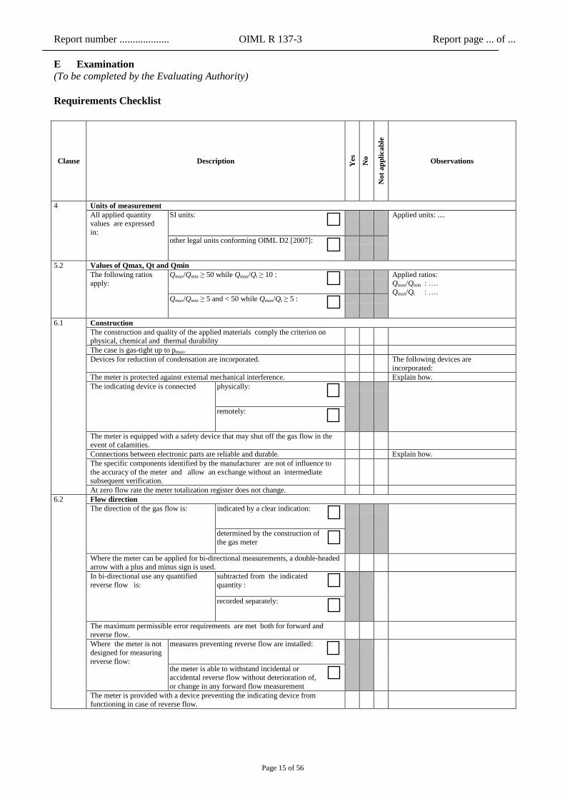
E Examination
(To be completed by the Evaluating Authority)
Requirements Checklist
Clause Description Yes
No
No
t a
pp
lica
ble
Observations
4 Units of measurement
All applied quantity values are expressed
in:
SI units:
Applied units: ....
other legal units conforming OIML D2 [2007]:
5.2 Values of Qmax, Qt and Qmin
The following ratios apply:
Qmax/Qmin ≥ 50 while Qmax/Qt ≥ 10 :
Applied ratios: Qmax/Qmin : ….
Qmax/Qt : …. Qmax/Qmin ≥ 5 and < 50 while Qmax/Qt ≥ 5 :
6.1 Construction
The construction and quality of the applied materials comply the criterion on physical, chemical and thermal durability
The case is gas-tight up to pmax.
Devices for reduction of condensation are incorporated. The following devices are
incorporated:
The meter is protected against external mechanical interference. Explain how.
The indicating device is connected physically:
remotely:
The meter is equipped with a safety device that may shut off the gas flow in the event of calamities.
Connections between electronic parts are reliable and durable. Explain how.
The specific components identified by the manufacturer are not of influence to
the accuracy of the meter and allow an exchange without an intermediate subsequent verification.
At zero flow rate the meter totalization register does not change.
6.2 Flow direction
The direction of the gas flow is:
indicated by a clear indication:
determined by the construction of
the gas meter
Where the meter can be applied for bi-directional measurements, a double-headed arrow with a plus and minus sign is used.
In bi-directional use any quantified
reverse flow is:
subtracted from the indicated
quantity :
recorded separately:
The maximum permissible error requirements are met both for forward and reverse flow.
Where the meter is not
designed for measuring
reverse flow:
measures preventing reverse flow are installed:
the meter is able to withstand incidental or accidental reverse flow without deterioration of,
or change in any forward flow measurement
The meter is provided with a device preventing the indicating device from functioning in case of reverse flow.

Report number ................... OIML R 137-3 Report page ... of ...
Page 16 of 56
Clause Description
Yes
No
No
t a
pp
lica
ble
Observations
6.3 Indicating device
Kind of indicating device :
a) mechanical:
b) electromechanical or electronic:
a combination of a) and b) above:
The quantity of gas is indicated in a clear way and unambiguous,
The indication cannot be reset and is non-volatile.
The applied decimal separtor is clear.
In case one display is applied for different indications it is made clear which is the
actual kind of quantity displayed
The indicating device is able to show at least 1.000 h of operation at Qmax without returning to the original reading.
Number of digits:
The least significant digit doesn’t exceed the quantity of gas passed during one
hour at Qmin.
Value of the least significant digit:
The mechanical indicating device fulfils the requirements on dimensions and appearance of numericals
A display test facility is provided.( electromechanical or electronic indicating
devices only)
Any applied remote indicating device clearly identifies the associated gas meter. The integrity of the communication is checked .
Report number ................... OIML R 137-3 Report page ... of ...
Page 17 of 56
Clause Description Yes
No
No
t a
pp
lica
ble
Observations
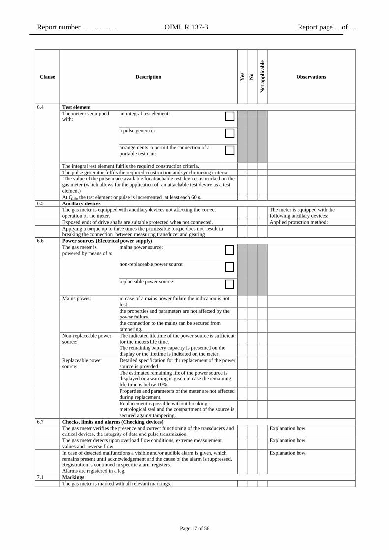
6.4 Test element
The meter is equipped
with:
an integral test element:
a pulse generator:
arrangements to permit the connection of a
portable test unit:
The integral test element fulfils the required construction criteria.
The pulse generator fulfils the required construction and synchronizing criteria.
The value of the pulse made available for attachable test devices is marked on the gas meter (which allows for the application of an attachable test device as a test
element)
At Qmin the test element or pulse is incremented at least each 60 s.
6.5 Ancillary devices
The gas meter is equipped with ancillary devices not affecting the correct operation of the meter.
The meter is equipped with the following ancillary devices:
Exposed ends of drive shafts are suitable protected when not connected. Applied protection method:
Applying a torque up to three times the permissible torque does not result in
breaking the connection between measuring transducer and gearing
6.6 Power sources (Electrical power supply)
The gas meter is
powered by means of a:
mains power source:
non-replaceable power source:
replaceable power source:
Mains power: in case of a mains power failure the indication is not
lost.
the properties and parameters are not affected by the power failure.
the connection to the mains can be secured from
tampering.
Non-replaceable power source:
The indicated lifetime of the power source is sufficient for the meters life time.
The remaining battery capacity is presented on the
display or the lifetime is indicated on the meter.
Replaceable power source:
Detailed specification for the replacement of the power source is provided .
The estimated remaining life of the power source is
displayed or a warning is given in case the remaining life time is below 10%.
Properties and parameters of the meter are not affected
during replacement.
Replacement is possible without breaking a
metrological seal and the compartment of the source is
secured against tampering.
6.7 Checks, limits and alarms (Checking devices)
The gas meter verifies the presence and correct functioning of the transducers and critical devices, the integrity of data and pulse transmission.
Explanation how.
The gas meter detects upon overload flow conditions, extreme measurement
values and reverse flow.
Explanation how.
In case of detected malfunctions a visible and/or audible alarm is given, which remains present until acknowledgement and the cause of the alarm is suppressed.
Registration is continued in specific alarm registers.
Alarms are registered in a log.
Explanation how.
7.1 Markings
The gas meter is marked with all relevant markings.
Report number ................... OIML R 137-3 Report page ... of ...
Page 18 of 56
Clause Description Yes
No
No
t a
pp
lica
ble
Observations
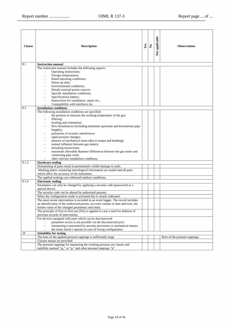
8.1 Instruction manual
The instruction manual includes the following aspects:
- Operating instructions;
- Storage temperatures; - Rated operating conditions;
- Warm up time;
- Environmental conditions; - Details external power sources;
- Specific installation conditions;
- Specifications battery; - Instructions for installation, repair etc.;
- Compatibility with interfaces etc.
8.2 Installation conditions
The following installation conditions are specified: - the position to measure the working temperature of the gas;
- filtering;
- leveling and orientation; - flow disturbances (including minimum upstream and downstream pipe
lengths);
- pulsations of acoustic interference; - rapid pressure changes;
- absence of mechanical stress (due to torque and bending); - mutual influence between gas meters;
- mounting instructions;
- maximum allowable diameter differences between the gas meter and connecting pipe work;
- other relevant installation conditions.
9.1.3 Hardware sealing
Dismantling of parts result in permanently visible damage to seals.
Marking plates containing metrological information are sealed and all parts
which affect the accuracy of the instrument.
The applied sealings can withstand outdoor conditions.
9.1.4 Electronic sealing
Parameters can only be changed by applying a security code (password) or a special device.
The security code can be altered by authorized persons.
When the configuration mode is activated this is clearly indicated.
The most recent intervention is recorded in an event logger. The record includes
an identification of the authorized person, an event counter or date and time, the former value of the changed parameters and totals.
The principle of first-in-first-out (fifo) is applied in case a need for deletion of
previous records of intervention.
For devices equipped with parts which can be disconnected: - parameter access is not possible via the disconnected port;
- interposing is prevented by security provisions or mechanical means; - the meter doesn’t operate in case of wrong configuration.
10 Suitability for testing
The bore of the applied pressure tappings is sufficiently large Bore of the pressure tappings:
Closure means are provided
The pressure tappings for measuring the working pressure are clearly and indelibly marked “pm” or “pr” and other pressure tappings “p”.
Report number ................... OIML R 137-3 Report page ... of ...
Page 19 of 56
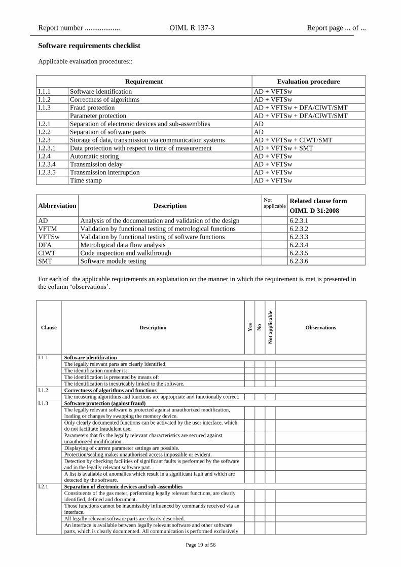
Software requirements checklist
Applicable evaluation procedures::
Requirement Evaluation procedure
I.1.1 Software identification AD + VFTSw
I.1.2 Correctness of algorithms AD + VFTSw
I.1.3 Fraud protection AD + VFTSw + DFA/CIWT/SMT
Parameter protection AD + VFTSw + DFA/CIWT/SMT
I.2.1 Separation of electronic devices and sub-assemblies AD
I.2.2 Separation of software parts AD
I.2.3 Storage of data, transmission via communication systems AD + VFTSw + CIWT/SMT
I.2.3.1 Data protection with respect to time of measurement AD + VFTSw + SMT
I.2.4 Automatic storing AD + VFTSw
I.2.3.4 Transmission delay AD + VFTSw
I.2.3.5 Transmission interruption AD + VFTSw
Time stamp AD + VFTSw
Abbreviation Description Not applicable
Related clause form
OIML D 31:2008
AD Analysis of the documentation and validation of the design 6.2.3.1
VFTM Validation by functional testing of metrological functions 6.2.3.2
VFTSw Validation by functional testing of software functions 6.2.3.3
DFA Metrological data flow analysis 6.2.3.4
CIWT Code inspection and walkthrough 6.2.3.5
SMT Software module testing 6.2.3.6
For each of the applicable requirements an explanation on the manner in which the requirement is met is presented in
the column ‘observations’.
Clause Description Yes
No
No
t a
pp
lica
ble
Observations
I.1.1 Software identification
The legally relevant parts are clearly identified.
The identification number is:
The identification is presented by means of:
The identification is inextricably linked to the software.
I.1.2 Correctness of algorithms and functions
The measuring algorithms and functions are appropriate and functionally correct.
I.1.3 Software protection (against fraud)
The legally relevant software is protected against unauthorized modification,
loading or changes by swapping the memory device.
Only clearly documented functions can be activated by the user interface, which do not facilitate fraudulent use.
Parameters that fix the legally relevant characteristics are secured against
unauthorized modification.
Displaying of current parameter settings are possible.
Protection/sealing makes unauthorised access impossible or evident.
Detection by checking facilities of significant faults is performed by the software
and in the legally relevant software part.
A list is available of anomalies which result in a significant fault and which are detected by the software.
I.2.1 Separation of electronic devices and sub-assemblies
Constituents of the gas meter, performing legally relevant functions, are clearly
identified, defined and document.
Those functions cannot be inadmissibly influenced by commands received via an
interface.
All legally relevant software parts are clearly described.
An interface is available between legally relevant software and other software parts, which is clearly documented. All communication is performed exclusively
Report number ................... OIML R 137-3 Report page ... of ...
Page 20 of 56
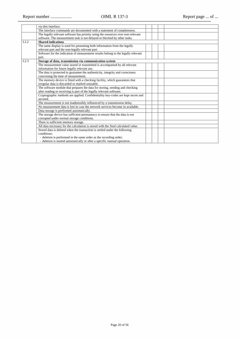
via this interface.
The interface commands are documented with a statement of completeness.
The legally relevant software has priority using the resources over non-relevant
software. The measurement task is not delayed or blocked by other tasks.
I.2.2 Shared indications
The same display is used for presenting both information from the legally
relevant part and the non-legally relevant part.
Software for the indication of measurement results belong to the legally relevant
part.
I.2.3 Storage of data, transmission via communication system
The measurement value stored or transmitted is accompanied by all relevant information for future legally relevant use.
The data is protected to guarantee the authenticity, integrity and correctness
concerning the time of measurement.
The memory device is fitted with a checking facility, which guarantees that irregular data is discarded or marked unusable.
The software module that prepares the data for storing, sending and checking
after reading or receiving is part of the legally relevant software.
Cryptographic methods are applied. Confidentiality key-codes are kept secret and secured.
The measurement is not inadmissibly influenced by a transmission delay.
No measurement data is lost in case the network services become in available.
Data storage is performed automatically.
The storage device has sufficient permanency to ensure that the data is not corrupted under normal storage conditions.
There is sufficient memory storage.
All data necessary for the calculation is stored with the final calculated value.
Stored data is deleted when the transaction is settled under the following conditions:
- deletion is performed in the same order as the recording order;
- deletion is started automatically or after a specific manual operation.

Report number ................... OIML R 137-3 Report page ... of ...
Page 21 of 56
F Performance tests
Concerning the performance tests the following maximum permissible errors have been applied:
Flow rate Q
Accuracy class
0.5 1 1.5
Qmin ≤ Q < Qt ± 1 % ± 2 % ± 3 %
Qt ≤ Q ≤ Qmax ± 0.5 % ± 1 % ± 1.5 %
If applicable the following relaxation on MPE has been applied:
(Applicable to gas meters with built-in conversion devices, showing the volume at base volume only)
In addition to the maximum permissible errors as indicated in the table above an increased
by 0.5 % in the temperature range of (tsp – 15) °C to (tsp + 15) °C and an additional
increase of 0.5 % per additional interval of 10 °C outside this temperature range
Applicable temperature tsp :
The following rate(s) for the weighted mean error (WME) has been applied:
Flow rate Q
Accuracy class
0.5 1 1.5
WME ± 0.2 % ± 0.4 % ± 0.6 %
Report number ................... OIML R 137-3 Report page ... of ...
Page 22 of 56
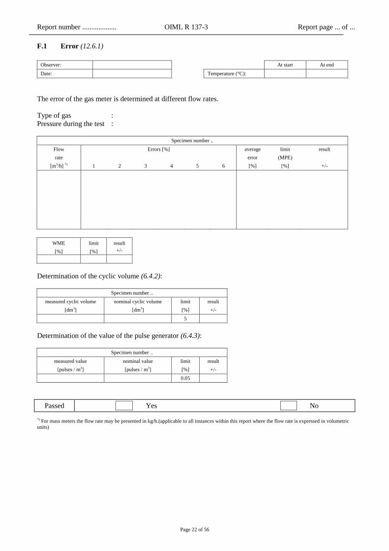
F.1 Error (12.6.1)
Observer: At start At end
Date: Temperature (°C):
The error of the gas meter is determined at different flow rates.
Type of gas :
Pressure during the test :
Specimen number ..
Flow Errors [%] average limit result
rate
error (MPE)
[m3/h] *) 1 2 3 4 5 6 [%] [%] +/-
WME limit result
[%] [%] +/-
Determination of the cyclic volume (6.4.2):
Specimen number ..
measured cyclic volume nominal cyclic volume limit result
[dm3] [dm3] [%] +/-
5
Determination of the value of the pulse generator (6.4.3):
Specimen number ..
measured value nominal value limit result
[pulses / m3] [pulses / m3] [%] +/-
0.05
Passed Yes No
*) For mass meters the flow rate may be presented in kg/h.(applicable to all instances within this report where the flow rate is expressed in volumetric units)

Report number ................... OIML R 137-3 Report page ... of ...
Page 23 of 56
F.2 Reproducibility (12.6.2)
Observer: At start At end
Date: Temperature (°C):
The reproducibility of the gas meter is determined at different flow rates.
Type of gas :
Pressure during the test :
Specimen number ..
Flow Errors [%] maximum limit result
rate
difference (⅓ MPE)
[m3/h] 1 2 3 4 5 6 [%] [%] +/-
Applied operating pressure:
Passed Yes No
F.3 Repeatability (12.6.3)
Observer: At start At end
Date: Temperature (°C):
The repeatability of the gas meter is determined at different flow rates.
Type of gas :
Pressure during the test :
Specimen number ..
Flow Errors [%] maximum limit result
rate
difference (⅓ MPE)
[m3/h] 1 2 3 [%] [%] +/-
Qmax
Qt
Qmin
Applied operating pressure:
Passed Yes No

Report number ................... OIML R 137-3 Report page ... of ...
Page 24 of 56
F.4 Orientation (12.6.4)
Observer: At start At end
Date: Temperature (°C):
The error of the gas meter is determined at different orientations of the gas meter, as stated in the table
below.
Type of gas :
Pressure during the test :
Specimen number ..
Flow rate Errors [%] limit (MPE) result
[m3/h] horizontal vertical up vertical down [%] +/-
Specimen number ..
WME [%]
limit (WME) result
horizontal vertical up vertical down [%] +/-
Intermediate adjustments are necessary to meet the requirements:
Mark to be applied:
Passed Yes No
Report number ................... OIML R 137-3 Report page ... of ...
Page 25 of 56
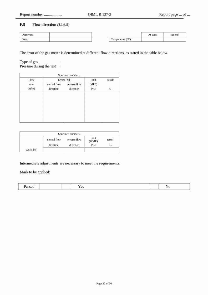
F.5 Flow direction (12.6.5)
Observer: At start At end
Date: Temperature (°C):
The error of the gas meter is determined at different flow directions, as stated in the table below.
Type of gas :
Pressure during the test :
Specimen number ..
Flow Errors [%] limit result
rate normal flow reverse flow (MPE)
[m3/h] direction direction [%] +/-
Specimen number ..
normal flow reverse flow limit
(WME) result
direction direction [%] +/-
WME [%]
Intermediate adjustments are necessary to meet the requirements:
Mark to be applied:
Passed Yes No
Report number ................... OIML R 137-3 Report page ... of ...
Page 26 of 56
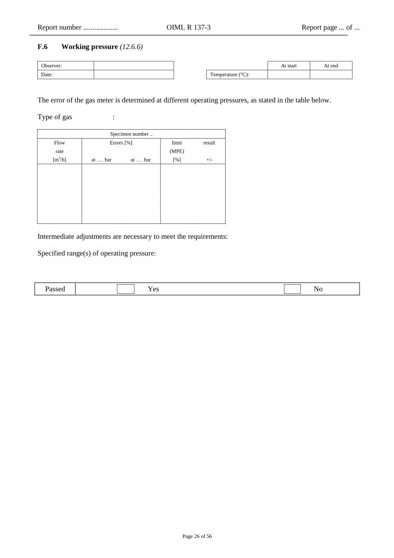
F.6 Working pressure (12.6.6)
Observer: At start At end
Date: Temperature (°C):
The error of the gas meter is determined at different operating pressures, as stated in the table below.
Type of gas :
Specimen number ..
Flow Errors [%] limit result
rate
(MPE)
[m3/h] at …. bar at …. bar [%] +/-
Intermediate adjustments are necessary to meet the requirements:
Specified range(s) of operating pressure:
Passed Yes No
Report number ................... OIML R 137-3 Report page ... of ...
Page 27 of 56
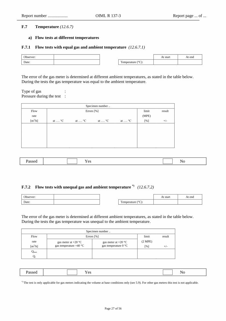
F.7 Temperature (12.6.7)
a) Flow tests at different temperatures
F.7.1 Flow tests with equal gas and ambient temperature (12.6.7.1)
Observer: At start At end
Date: Temperature (°C):
The error of the gas meter is determined at different ambient temperatures, as stated in the table below.
During the tests the gas temperature was equal to the ambient temperature.
Type of gas :
Pressure during the test :
Specimen number ..
Flow Errors [%] limit result
rate
(MPE)
[m3/h] at …. °C at …. °C at …. °C at …. °C [%] +/-
Passed Yes No
F.7.2 Flow tests with unequal gas and ambient temperature *)
(12.6.7.2)
Observer: At start At end
Date: Temperature (°C):
The error of the gas meter is determined at different ambient temperatures, as stated in the table below.
During the tests the gas temperature was unequal to the ambient temperature.
Specimen number ..
Flow Errors [%] limit result
rate gas meter at +20 °C
gas temperature +40 °C
gas meter at +20 °C
gas temperature 0 °C
(2 MPE)
[m3/h] [%] +/-
Qmax
Qt
Passed Yes No
*) The test is only applicable for gas meters indicating the volume at base conditions only (see 5.9). For other gas meters this test is not applicable.
Report number ................... OIML R 137-3 Report page ... of ...
Page 28 of 56
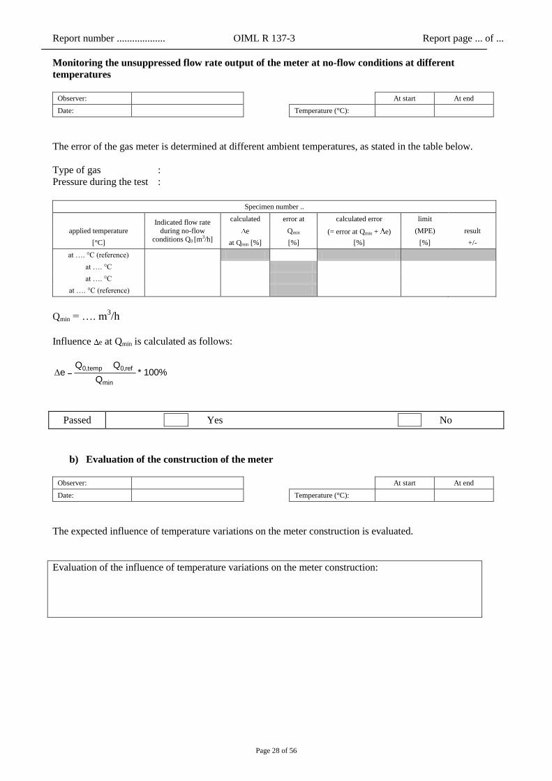
Monitoring the unsuppressed flow rate output of the meter at no-flow conditions at different
temperatures
Observer: At start At end
Date: Temperature (°C):
The error of the gas meter is determined at different ambient temperatures, as stated in the table below.
Type of gas :
Pressure during the test :
Specimen number ..
Indicated flow rate
during no-flow conditions Q0 [m
3/h]
calculated error at calculated error limit
applied temperature e Qmin (= error at Qmin + e) (MPE) result
[°C] at Qmin [%] [%] [%] [%] +/-
at …. °C (reference)
at …. °C
at …. °C
at …. °C (reference)
Qmin = …. m3/h
Influence e at Qmin is calculated as follows:
100% * Q
Q Q e
min
ref0,temp0,Δ
Passed Yes No
b) Evaluation of the construction of the meter
Observer: At start At end
Date: Temperature (°C):
The expected influence of temperature variations on the meter construction is evaluated.
Evaluation of the influence of temperature variations on the meter construction:

Report number ................... OIML R 137-3 Report page ... of ...
Page 29 of 56
F.8 Flow disturbance (12.6.8)
The effect of disturbances to the accuracy of the gas meter is determined at different conditions, as stated in
the tables below.
a) mild disturbances
Observer: At start At end
Date: Temperature (°C):
Applied piping configuration :
Applied flow conditioner :
Applied operating pressure :
Type of gas :
Specimen number ..
Flow
rate at ref.
condi-
tions
single double out-of plane
bend expander reducer
diameter step max. shift
(⅓ MPE) result
[m3/h] 90° bend rotating
right rotating
left +3% -3% [%] +/-
0.25
Qmax
error [%]
shift [%]
0.4 Qmax error [%]
shift [%]
Qmax error [%]
shift [%]
For ultrasonic gas meters, the same test is performed while adding an extra 10D straight pipe length (B.2.5):
Specimen number ..
Flow
rate at ref.
condi-
tions
single double out-of plane
bend expander reducer
diameter step max. shift
(⅓ MPE) result
[m3/h] 90° bend rotating
right
rotating
left +3% -3% [%] +/-
0.25 Qmax
error [%]
shift [%]
0.4 Qmax error [%]
shift [%]
Qmax error [%]
shift [%]

Report number ................... OIML R 137-3 Report page ... of ...
Page 30 of 56
b) severe disturbances
Observer: At start At end
Date: Temperature (°C):
Applied piping configuration :
Applied flow conditioner :
Applied operating pressure :
Type of gas :
Specimen number ..
Flow Errors [%] max. shift
rate
at ref. double out-of plane bend with
half pipe area plate (⅓ MPE) result
[m3/h] conditions rotating right rotating left [%] +/-
0.25 Qmax error [%]
shift [%]
0.4 Qmax error [%]
shift [%]
Qmax error [%]
shift [%]
For ultrasonic gas meters, the same test is performed while adding an extra 10D straight pipe length (B.2.5):
Specimen number ..
Flow Errors [%] max. shift
rate
at ref. double out-of plane bend with
half pipe area plate (⅓ MPE) result
[m3/h] conditions rotating right rotating left [%] +/-
0.25 Qmax error [%]
shift [%]
0.4 Qmax error [%]
shift [%]
Qmax error [%]
shift [%]
Passed Yes No

Report number ................... OIML R 137-3 Report page ... of ...
Page 31 of 56
F.9 Durability (12.6.9)
Observer: At start At end
Date: Temperature (°C):
The accuracy measurements before and after the exposure to the durability test are performed with air.
The gas meters is exposed to a durability test with the following characteristics:
- duration : 2.000 h
- flow rate : Qmax
- type of gas : natural gas
- operating pressure :
Specimen number ..
Flow Errors [%] limit before durability
(MPE)
limit after durability
(2 MPE)
rate before the durability
test
after the durability
test
result shift limit *) result
[m3/h] [%] [%] +/- [%] [%] +/-
Specimen number ..
Flow Errors [%] limit before durability
(MPE)
limit after durability
(2 MPE)
rate before the
durability test
after the
durability test
result shift limit *) result
[m3/h] [%] [%] +/- [%] [%] +/-
Specimen number ..
Flow Errors [%] limit before
durability (MPE)
limit after
durability (2 MPE)
rate before the
durability
test
after the
durability
test
result shift limit *) result
[m3/h] [%] [%] +/- [%] [%] +/-
*) MPE for class 1.5 or ½ MPE for other classes.
Passed Yes No

Report number ................... OIML R 137-3 Report page ... of ...
Page 32 of 56
F.10 Drive shaft (torque) (12.6.10)
Observer: At start At end
Date: Temperature (°C):
The gas meter is exposed to the maximum permissible torque with the following characteristics:
- torque : … N.mm
Type of gas :
Pressure during the test :
Specimen number ..
Flow Errors [%] limit
rate without any with maximum shift (⅓ MPE) result
[m3/h] torque torque [%] [%] +/-
Qmin
Passed Yes No
F.11 Overload flow (12.6.11)
Observer: At start At end
Date: Temperature (°C):
The gas meter is exposed to overload an flow rate with the following characteristics:
- overload flow rate : 1.2 Qmax
- duration : 1 hour
Type of gas :
Pressure during the test :
Specimen number ..
Flow Errors [%] limit before overload
flow
(MPE)
limit after overload
flow
(MPE)
limit
rate before
overload
flow
after
overload
flow
result shift (⅓ MPE) result
[m3/h] [%] [%] +/- [%] [%] +/-
Passed Yes No

Report number ................... OIML R 137-3 Report page ... of ...
Page 33 of 56
F.12 Different gases (12.6.12)
Observer: At start At end
Date: Temperature (°C):
The gas meter is examined with the gases as stated in the table below.
Pressure during the test :
Specimen number ..
Flow Errors [%] limit
rate with with with (MPE) result
[m3/h] air ……. ……. [%] +/-
Intermediate adjustments are necessary to meet the requirements:
Specified range of operating gases:
Passed Yes No

Report number ................... OIML R 137-3 Report page ... of ...
Page 34 of 56
F.13 Vibrations and shocks (12.6.13)
Observer: At start At end
Date: Temperature (°C):
The gas meter is exposed to vibrations and shocks with the following characteristics:
vibrations:
- total frequency range : 10 Hz – 150 Hz
- total RMS level : 7 m.s-2
- ASD level 10 – 20 Hz : 1 m2.s
-3
- ASD level 20 – 150 Hz : -3 dB/octave
shocks:
- height of fall : 50 mm
Type of gas :
Pressure during the test :
Specimen number ..
Flow Errors [%] limit
rate before after shift (½ MPE) result
[m3/h] vibrations
and shocks
vibrations
and shocks [%] [%] +/-
Passed Yes No

Report number ................... OIML R 137-3 Report page ... of ...
Page 35 of 56
F.14 Interchangeable components (12.6.14)
Observer: At start At end
Date: Temperature (°C):
The following component in the gas meter can be exchanged:
The accuracy of the gas meter is while using the starting configuration, after interchange of the component
and after reinstalling the original component.
Type of gas :
Pressure during the test :
Specimen number ..
Flow rate
starting after after max. difference
(⅓ MPE) result
[m3/h] configuration interchange reinstalling [%] +/-
Qt error [%]
shift [%]
Passed Yes No

Report number ................... OIML R 137-3 Report page ... of ...
Page 36 of 56
F.15 Electronics (12.6.15)
The electronics are examined by means of the tests as stated below.
Examined part : complete gas meter / separate electronic device (to be indicated)
Conditions during the tests
Type of gas :
Pressure :
F.15.1 Dry heat (A.4.1.1)
Observer: At start At end
Date: Temperature (°C):
At the upper specified temperature the accuracy of the gas meter is examined.
Applied test method: with actual flow
Specimen number ..
Flow Errors [%] limit result
rate
(MPE)
[m3/h] at …. °C [%] +/-
Applied test method: at no-flow conditions while monitoring the unsuppressed flow rate output of the meter
Specimen number ..
Indicated flow rate
during no-flow
conditions Q0 [m3/h]
calculated error at calculated error limit
applied temperature e Qmin (= error at Qmin + e) (MPE) result
[°C] at Qmin [%] [%] [%] [%] +/-
at …. °C (reference)
at …. °C
at …. °C (reference)
Qmin = …. m3/h
Influence e at Qmin is calculated as follows:
100% * Q
Q Q e
min
ref0,temp0,Δ
Report number ................... OIML R 137-3 Report page ... of ...
Page 37 of 56
Passed Yes No
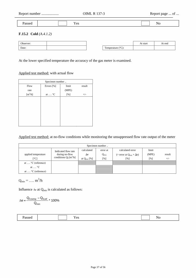
F.15.2 Cold (A.4.1.2)
Observer: At start At end
Date: Temperature (°C):
At the lower specified temperature the accuracy of the gas meter is examined.
Applied test method: with actual flow
Specimen number ..
Flow Errors [%] limit result
rate
(MPE)
[m3/h] at …. °C [%] +/-
Applied test method: at no-flow conditions while monitoring the unsuppressed flow rate output of the meter
Specimen number ..
Indicated flow rate
during no-flow conditions Q0 [m
3/h]
calculated error at calculated error limit
applied temperature e Qmin (= error at Qmin + e) (MPE) result
[°C] at Qmin [%] [%] [%] [%] +/-
at …. °C (reference)
at …. °C
at …. °C (reference)
Qmin = …. m3/h
Influence e at Qmin is calculated as follows:
100% * Q
Q Q e
min
ref0,temp0,Δ
Passed Yes No

Report number ................... OIML R 137-3 Report page ... of ...
Page 38 of 56
F.15.3 Damp heat, steady-state (non condensing) (A.4.2.1)
Observer: At start At end
Date: Temperature (°C):
The gas meter is exposed to the upper temperature at 93% R.H. for 4 days.
The accuracy of the gas meter is examined:
- at reference conditions before the increase of the temperature;
- at the end of the upper temperature phase;
- at reference conditions, 24 hours after the decrease of temperature.
Applied test method: with actual flow
Specimen number ..
Flow Errors [%] limit result
rate at …. °C at …. °C at …. °C (MPE)
[m3/h] (ref. conditions) (ref. conditions) [%] +/-
Applied test method: at no-flow conditions while monitoring the unsuppressed flow rate output of the meter
Specimen number ..
Indicated flow rate
during no-flow
conditions Q0 [m3/h]
calculated error at calculated error limit
applied temperature e Qmin (= error at Qmin + e) (MPE) result
[°C] at Qmin [%] [%] [%] [%] +/-
at …. °C (reference)
at …. °C
at …. °C (reference)
Qmin = …. m3/h
Influence e at Qmin is calculated as follows:
100% * Q
Q Q e
min
ref0,temp0,Δ
Passed Yes No
Report number ................... OIML R 137-3 Report page ... of ...
Page 39 of 56
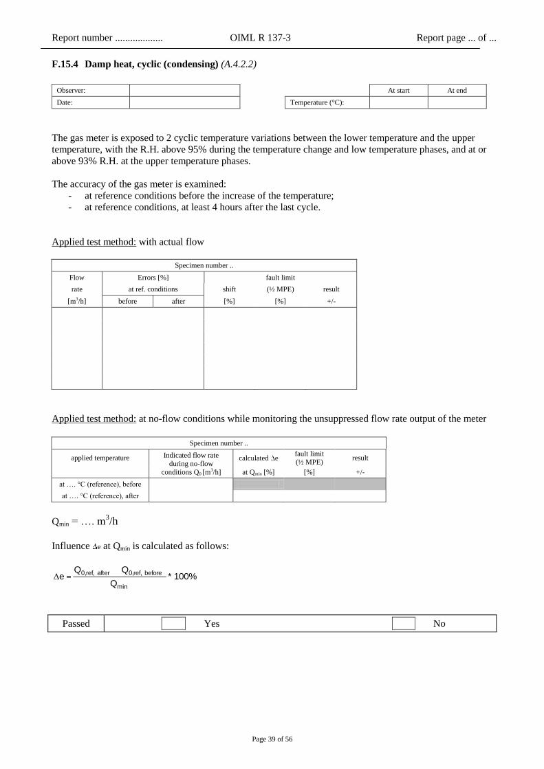
F.15.4 Damp heat, cyclic (condensing) (A.4.2.2)
Observer: At start At end
Date: Temperature (°C):
The gas meter is exposed to 2 cyclic temperature variations between the lower temperature and the upper
temperature, with the R.H. above 95% during the temperature change and low temperature phases, and at or
above 93% R.H. at the upper temperature phases.
The accuracy of the gas meter is examined:
- at reference conditions before the increase of the temperature;
- at reference conditions, at least 4 hours after the last cycle.
Applied test method: with actual flow
Specimen number ..
Flow Errors [%] fault limit
rate at ref. conditions shift (½ MPE) result
[m3/h] before after [%] [%] +/-
Applied test method: at no-flow conditions while monitoring the unsuppressed flow rate output of the meter
Specimen number ..
applied temperature Indicated flow rate
during no-flow
conditions Q0 [m3/h]
calculated e fault limit (½ MPE)
result
at Qmin [%] [%] +/-
at …. °C (reference), before
at …. °C (reference), after
Qmin = …. m3/h
Influence e at Qmin is calculated as follows:
100% * Q
Q Q e
min
before ref,0,after ref,0,Δ
Passed Yes No
Report number ................... OIML R 137-3 Report page ... of ...
Page 40 of 56
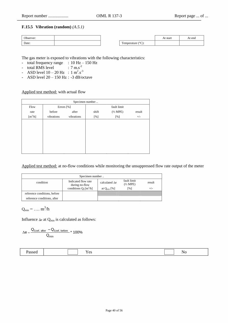
F.15.5 Vibration (random) (A.5.1)
Observer: At start At end
Date: Temperature (°C):
The gas meter is exposed to vibrations with the following characteristics:
- total frequency range : 10 Hz – 150 Hz
- total RMS level : 7 m.s-2
- ASD level 10 – 20 Hz : 1 m2.s
-3
- ASD level 20 – 150 Hz : -3 dB/octave
Applied test method: with actual flow
Specimen number ..
Flow Errors [%] fault limit
rate before after shift (½ MPE) result
[m3/h] vibrations vibrations [%] [%] +/-
Applied test method: at no-flow conditions while monitoring the unsuppressed flow rate output of the meter
Specimen number ..
condition Indicated flow rate
during no-flow
conditions Q0 [m3/h]
calculated e fault limit (½ MPE)
result
at Qmin [%] [%] +/-
reference conditions, before
reference conditions, after
Qmin = …. m3/h
Influence e at Qmin is calculated as follows:
100% * Q
Q Q e
min
before ref,0,after ref,0,Δ
Passed Yes No
Report number ................... OIML R 137-3 Report page ... of ...
Page 41 of 56
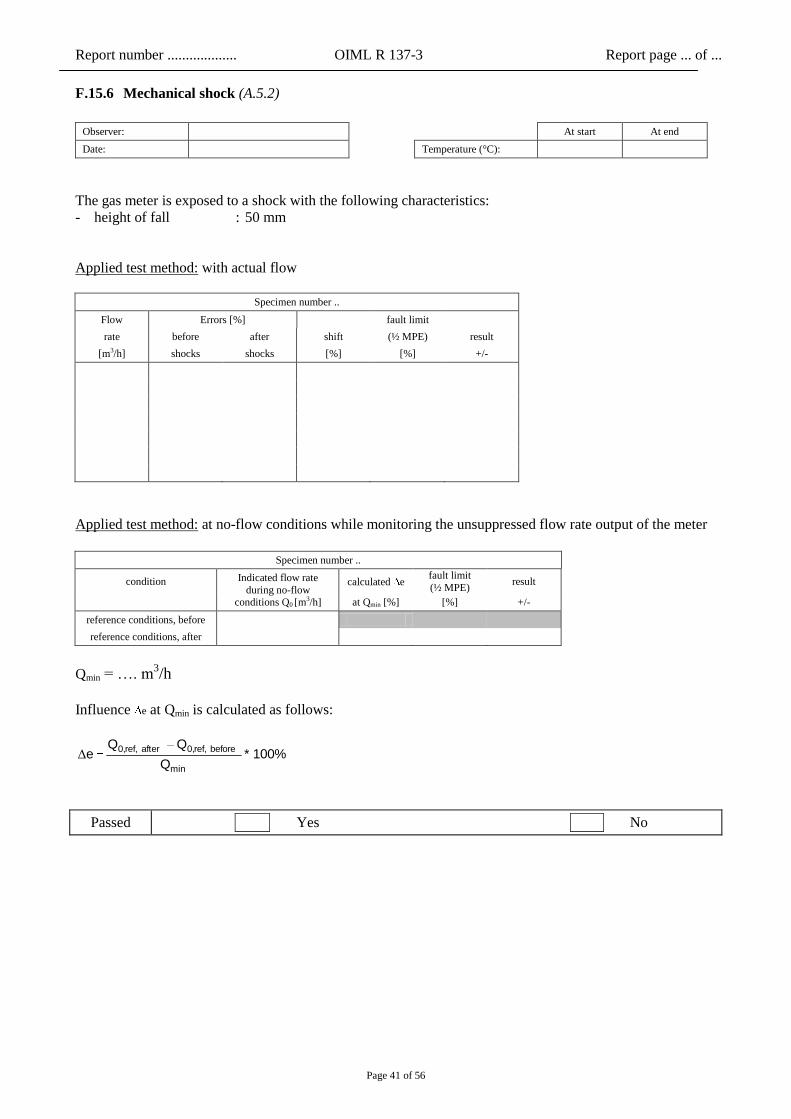
F.15.6 Mechanical shock (A.5.2)
Observer: At start At end
Date: Temperature (°C):
The gas meter is exposed to a shock with the following characteristics:
- height of fall : 50 mm
Applied test method: with actual flow
Specimen number ..
Flow Errors [%] fault limit
rate before after shift (½ MPE) result
[m3/h] shocks shocks [%] [%] +/-
Applied test method: at no-flow conditions while monitoring the unsuppressed flow rate output of the meter
Specimen number ..
condition Indicated flow rate
during no-flow conditions Q0 [m
3/h]
calculated e fault limit
(½ MPE) result
at Qmin [%] [%] +/-
reference conditions, before
reference conditions, after
Qmin = …. m3/h
Influence e at Qmin is calculated as follows:
100% * Q
Q Q e
min
before ref,0,after ref,0,Δ
Passed Yes No

Report number ................... OIML R 137-3 Report page ... of ...
Page 42 of 56
F.15.7 Radiated, RF, electromagnetic fields (A.6.1.1)
Observer: At start At end
Date: Temperature (°C):
The gas meter is exposed to radiated, RF, electromagnetic fields with the following characteristics:
- frequency range : ..... MHz – 3 GHz *)
- field strength : 10 V/m
- modulation : 80 % AM, 1 kHz, sine wave
- step size : 1% of the preceding frequency value **)
Applied test method: with actual flow
Specimen number ..
Flow Radiated field condition fault limit
rate
measured shift (MPE) result [m3/h]
errors [%] [%] [%] +/-
no field
Horizontal polarised field
Vertical polarised field
Applied test method: at no-flow conditions while monitoring the unsuppressed flow rate output of the meter
Specimen number ..
Radiated field condition
Indicated flow rate during no-flow conditions Q0
fault limit
[m3/h] calculated
e (MPE) result
at Qmin [%] [%] +/-
no field
Horizontal polarised field
Vertical polarised field
Qmin = …. m3/h
Influence e at Qmin is calculated as follows:
100% * Q
Q Q e
min
field no0,frequency0,Δ
Passed Yes No
*) start frequency of the sweep 26 MHz or 80 MHz dependent on whether cabling is applied
**) A stepwise frequency sweep is performed over the whole frequency range. At each step a measurement is performed and the fault value
calculated. However, in the test report the results of individual frequencies can be combined by presenting the overall result over the whole frequency range. Details on extremes, where relevant, shall be reported separately.

Report number ................... OIML R 137-3 Report page ... of ...
Page 43 of 56
F.15.8 Conducted radio-frequency fields (A.6.1.2)
Observer: At start At end
Date: Temperature (°C):
The gas meter is exposed to conducted radio-frequency fields with the following characteristics:
- frequency range : 0,15 MHz – 80 MHz
- field strength : 10 V e.m.f.
- modulation : 80 % AM, 1 kHz, sine wave
Applied test method: with actual flow
Specimen number ..
Flow cable which is fault limit
rate exposed to the measured shift (MPE) result
[m3/h] conducted fields errors [%] [%] [%] +/-
none (reference conditions)
power cable
cable ….
cable ….
cable ….
Applied test method: at no-flow conditions while monitoring the unsuppressed flow rate output of the meter
Specimen number ..
cable which is Indicated flow rate during
no-flow conditions Q0
fault limit
exposed to the calculated e (MPE) result
conducted fields [m3/h] at Qmin [%] [%] +/-
none (reference conditions)
power cable
cable ….
cable ….
cable ….
Qmin = …. m3/h
Influence e at Qmin is calculated as follows:
100% * Q
Q Q e
min
conditions ref.0,cable0,Δ
Passed Yes No

Report number ................... OIML R 137-3 Report page ... of ...
Page 44 of 56
F.15.9 Electrostatic discharge (A.6.2)
Observer: At start At end
Date: Temperature (°C):
The gas meter is exposed to electrostatic discharges with the following characteristics:
- contact discharges : 6 kV
- air discharges : 8 kV
Applied test method: with actual flow
Specimen number ..
Flow applied fault limit
rate discharges measured shift (½ MPE) result
[m3/h]
errors [%] [%] [%] +/-
none (reference conditions)
contact discharges positive
contact discharges negative
air discharges positive
air discharges negative
none (reference conditions)
Applied test method: at no-flow conditions while monitoring the unsuppressed flow rate output of the meter
Specimen number ..
applied Indicated flow rate during
no-flow conditions Q0
fault limit
discharges calculated e (½ MPE) result
[m3/h] at Qmin [%] [%] +/-
none (reference conditions)
contact discharges positive
contact discharges negative
air discharges positive
air discharges negative
none (reference conditions)
Qmin = …. m3/h
Influence e at Qmin is calculated as follows:
100% * Q
Q Q e
min
conditions ref.0,discharges0,Δ
Passed Yes No
Report number ................... OIML R 137-3 Report page ... of ...
Page 45 of 56
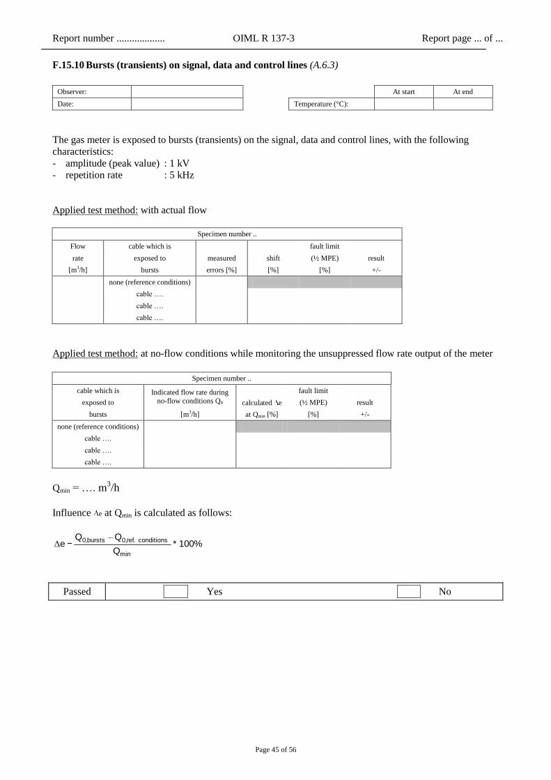
F.15.10 Bursts (transients) on signal, data and control lines (A.6.3)
Observer: At start At end
Date: Temperature (°C):
The gas meter is exposed to bursts (transients) on the signal, data and control lines, with the following
characteristics:
- amplitude (peak value) : 1 kV
- repetition rate : 5 kHz
Applied test method: with actual flow
Specimen number ..
Flow cable which is fault limit
rate exposed to measured shift (½ MPE) result
[m3/h] bursts errors [%] [%] [%] +/-
none (reference conditions)
cable ….
cable ….
cable ….
Applied test method: at no-flow conditions while monitoring the unsuppressed flow rate output of the meter
Specimen number ..
cable which is Indicated flow rate during
no-flow conditions Q0
fault limit
exposed to calculated e (½ MPE) result
bursts [m3/h] at Qmin [%] [%] +/-
none (reference conditions)
cable ….
cable ….
cable ….
Qmin = …. m3/h
Influence e at Qmin is calculated as follows:
100% * Q
Q Q e
min
conditions ref.0,bursts0,Δ
Passed Yes No
Report number ................... OIML R 137-3 Report page ... of ...
Page 46 of 56
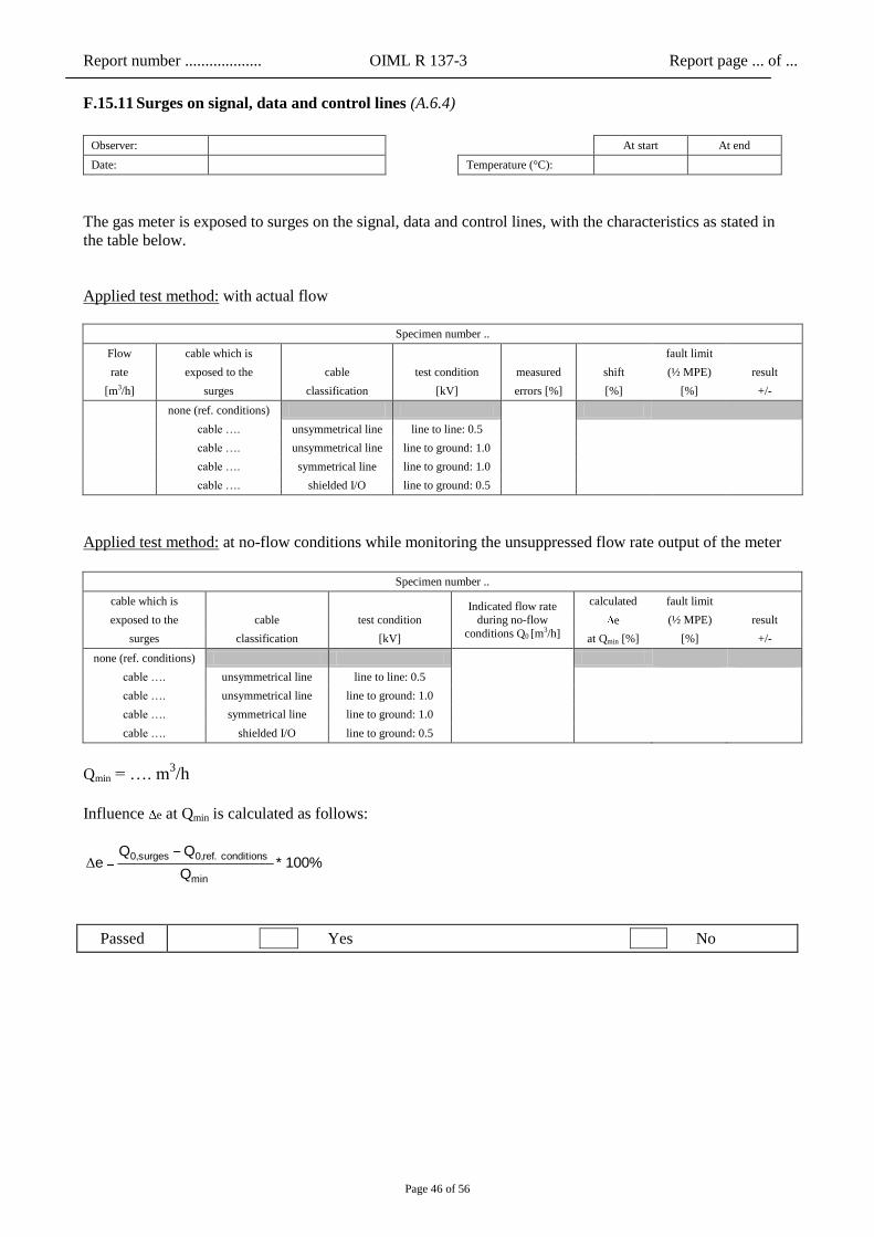
F.15.11 Surges on signal, data and control lines (A.6.4)
Observer: At start At end
Date: Temperature (°C):
The gas meter is exposed to surges on the signal, data and control lines, with the characteristics as stated in
the table below.
Applied test method: with actual flow
Specimen number ..
Flow cable which is fault limit
rate exposed to the cable test condition measured shift (½ MPE) result
[m3/h] surges classification [kV] errors [%] [%] [%] +/-
none (ref. conditions)
cable …. unsymmetrical line line to line: 0.5
cable …. unsymmetrical line line to ground: 1.0
cable …. symmetrical line line to ground: 1.0
cable …. shielded I/O line to ground: 0.5
Applied test method: at no-flow conditions while monitoring the unsuppressed flow rate output of the meter
Specimen number ..
cable which is Indicated flow rate
during no-flow
conditions Q0 [m3/h]
calculated fault limit
exposed to the cable test condition e (½ MPE) result
surges classification [kV] at Qmin [%] [%] +/-
none (ref. conditions)
cable …. unsymmetrical line line to line: 0.5
cable …. unsymmetrical line line to ground: 1.0
cable …. symmetrical line line to ground: 1.0
cable …. shielded I/O line to ground: 0.5
Qmin = …. m3/h
Influence e at Qmin is calculated as follows:
100% * Q
Q Q e
min
conditions ref.0,surges0,Δ
Passed Yes No
Report number ................... OIML R 137-3 Report page ... of ...
Page 47 of 56
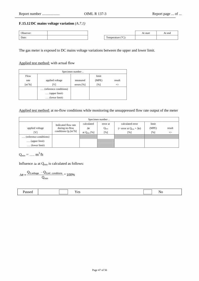
F.15.12 DC mains voltage variation (A.7.1)
Observer: At start At end
Date: Temperature (°C):
The gas meter is exposed to DC mains voltage variations between the upper and lower limit.
Applied test method: with actual flow
Specimen number ..
Flow
limit
rate applied voltage measured (MPE) result
[m3/h] [V] errors [%] [%] +/-
…. (reference conditions)
…. (upper limit)
…. (lower limit)
Applied test method: at no-flow conditions while monitoring the unsuppressed flow rate output of the meter
Specimen number ..
Indicated flow rate
during no-flow
conditions Q0 [m3/h]
calculated error at calculated error limit
applied voltage e Qmin (= error at Qmin + e) (MPE) result
[V] at Qmin [%] [%] [%] [%] +/-
…. (reference conditions)
…. (upper limit)
…. (lower limit)
Qmin = …. m3/h
Influence e at Qmin is calculated as follows:
100% * Q
Q Q e
min
conditions ref.0,voltage0,Δ
Passed Yes No

Report number ................... OIML R 137-3 Report page ... of ...
Page 48 of 56
F.15.13 AC mains voltage variation (A.7.2)
Observer: At start At end
Date: Temperature (°C):
The gas meter is exposed to AC mains voltage variations between the following limits:
- upper limit : Unom + 10%
- lower limit : Unom – 15%
Applied test method: with actual flow
Specimen number ..
Flow
limit
rate applied voltage measured (MPE) result
[m3/h] [V] errors [%] [%] +/-
…. (reference conditions)
…. (upper limit)
…. (lower limit)
Applied test method: at no-flow conditions while monitoring the unsuppressed flow rate output of the meter
Specimen number ..
Indicated flow rate
during no-flow conditions Q0 [m
3/h]
calculated error at calculated error limit
applied voltage e Qmin (= error at Qmin + e) (MPE) result
[V] at Qmin [%] [%] [%] [%] +/-
…. (reference conditions)
…. (upper limit)
…. (lower limit)
Qmin = …. m3/h
Influence e at Qmin is calculated as follows:
100% * Q
Q Q e
min
conditions ref.0,voltage0,Δ
Passed Yes No

Report number ................... OIML R 137-3 Report page ... of ...
Page 49 of 56
F.15.14 AC mains voltage dips and short interruptions (A.7.3)
Observer: At start At end
Date: Temperature (°C):
The gas meter is exposed to AC mains voltage dips and short interruptions, with the characteristics as stated
in the table below.
Applied test method: with actual flow
Specimen number ..
Flow voltage reduction measured
fault limit
rate reduction to duration errors shift (½ MPE) result
[m3/h] [%] [cycles] [%] [%] [%] +/-
no reduction (ref. conditions)
0 0.5
0 1
40 10 / 12
70 25 / 30
80 250 / 300
Applied test method: at no-flow conditions while monitoring the unsuppressed flow rate output of the meter
Specimen number ..
Indicated flow
rate during no-
flow conditions
Q0 [m3/h]
calculated error at calculated error fault limit
reduction to duration e Qmin (= error at Qmin + e) (½ MPE) result
[%] [cycles] at Qmin [%] [%] [%] [%] +/-
no reduction
(ref. conditions)
0 0.5
0 1
40 10 / 12
70 25 / 30
80 250 / 300
Qmin = …. m3/h
Influence e at Qmin is calculated as follows:
100% * Q
Q Q e
min
conditions ref.0,reduction0,Δ
Passed Yes No
Report number ................... OIML R 137-3 Report page ... of ...
Page 50 of 56
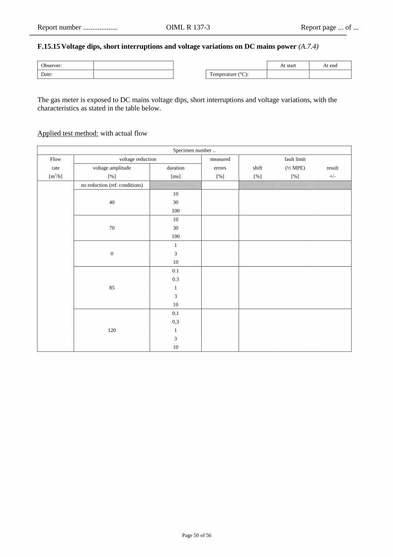
F.15.15 Voltage dips, short interruptions and voltage variations on DC mains power (A.7.4)
Observer: At start At end
Date: Temperature (°C):
The gas meter is exposed to DC mains voltage dips, short interruptions and voltage variations, with the
characteristics as stated in the table below.
Applied test method: with actual flow
Specimen number ..
Flow voltage reduction measured
fault limit
rate voltage amplitude duration errors shift (½ MPE) result
[m3/h] [%] [ms] [%] [%] [%] +/-
no reduction (ref. conditions)
40
10
30
100
70
10
30
100
0
1
3
10
85
0.1
0.3
1
3
10
120
0.1
0,3
1
3
10

Report number ................... OIML R 137-3 Report page ... of ...
Page 51 of 56
Applied test method: at no-flow conditions while monitoring the unsuppressed flow rate output of the meter
Specimen number ..
Indicated flow
rate during no-
flow conditions Q0 [m
3/h]
calculated error at calculated error fault limit
voltage
amplitude duration e Qmin (= error at Qmin + e) (½ MPE) result
[%] [ms] at Qmin [%] [%] [%] [%] +/-
no reduction (ref. conditions)
40
10
30
100
70
10
30
100
0
1
3
10
85
0.1
0.3
1
3
10
120
0.1
0.3
1
3
10
Qmin = …. m3/h
Influence e at Qmin is calculated as follows:
100% * Q
Q Q e
min
conditions ref.0,reduction0,Δ
Passed Yes No
Report number ................... OIML R 137-3 Report page ... of ...
Page 52 of 56
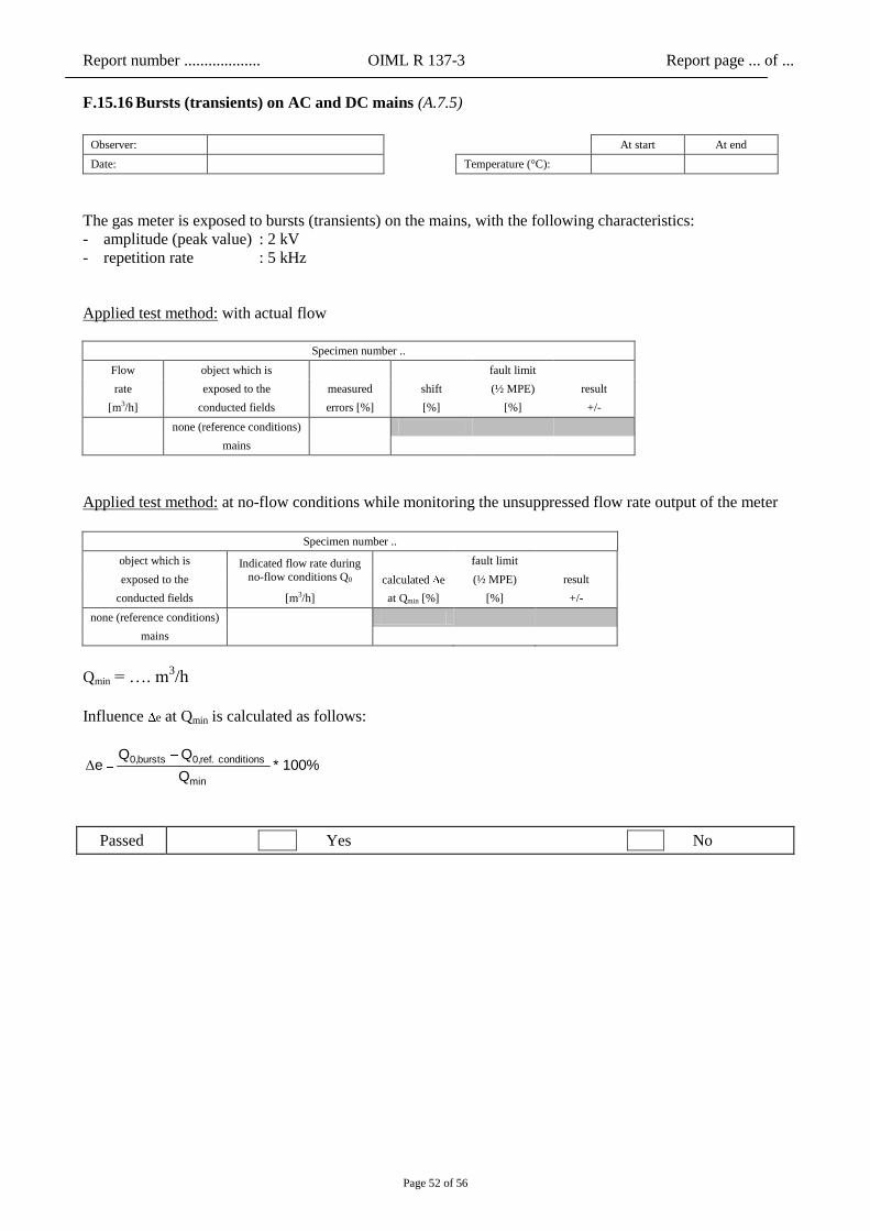
F.15.16 Bursts (transients) on AC and DC mains (A.7.5)
Observer: At start At end
Date: Temperature (°C):
The gas meter is exposed to bursts (transients) on the mains, with the following characteristics:
- amplitude (peak value) : 2 kV
- repetition rate : 5 kHz
Applied test method: with actual flow
Specimen number ..
Flow object which is fault limit
rate exposed to the measured shift (½ MPE) result
[m3/h] conducted fields errors [%] [%] [%] +/-
none (reference conditions)
mains
Applied test method: at no-flow conditions while monitoring the unsuppressed flow rate output of the meter
Specimen number ..
object which is Indicated flow rate during
no-flow conditions Q0
fault limit
exposed to the calculated e (½ MPE) result
conducted fields [m3/h] at Qmin [%] [%] +/-
none (reference conditions)
mains
Qmin = …. m3/h
Influence e at Qmin is calculated as follows:
100% * Q
Q Q e
min
conditions ref.0,bursts0,Δ
Passed Yes No
Report number ................... OIML R 137-3 Report page ... of ...
Page 53 of 56
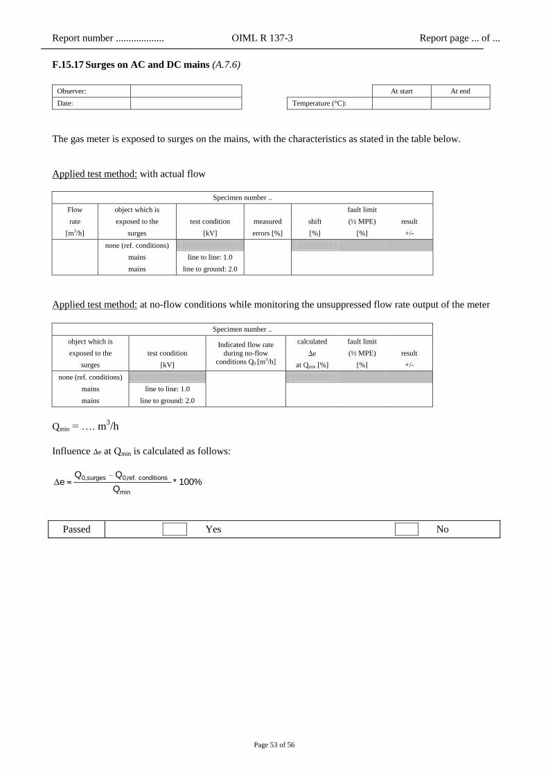
F.15.17 Surges on AC and DC mains (A.7.6)
Observer: At start At end
Date: Temperature (°C):
The gas meter is exposed to surges on the mains, with the characteristics as stated in the table below.
Applied test method: with actual flow
Specimen number ..
Flow object which is fault limit
rate exposed to the test condition measured shift (½ MPE) result
[m3/h] surges [kV] errors [%] [%] [%] +/-
none (ref. conditions)
mains line to line: 1.0
mains line to ground: 2.0
Applied test method: at no-flow conditions while monitoring the unsuppressed flow rate output of the meter
Specimen number ..
object which is Indicated flow rate
during no-flow
conditions Q0 [m3/h]
calculated fault limit
exposed to the test condition e (½ MPE) result
surges [kV] at Qmin [%] [%] +/-
none (ref. conditions)
mains line to line: 1.0
mains line to ground: 2.0
Qmin = …. m3/h
Influence e at Qmin is calculated as follows:
100% * Q
Q Q e
min
conditions ref.0,surges0,Δ
Passed Yes No
Report number ................... OIML R 137-3 Report page ... of ...
Page 54 of 56
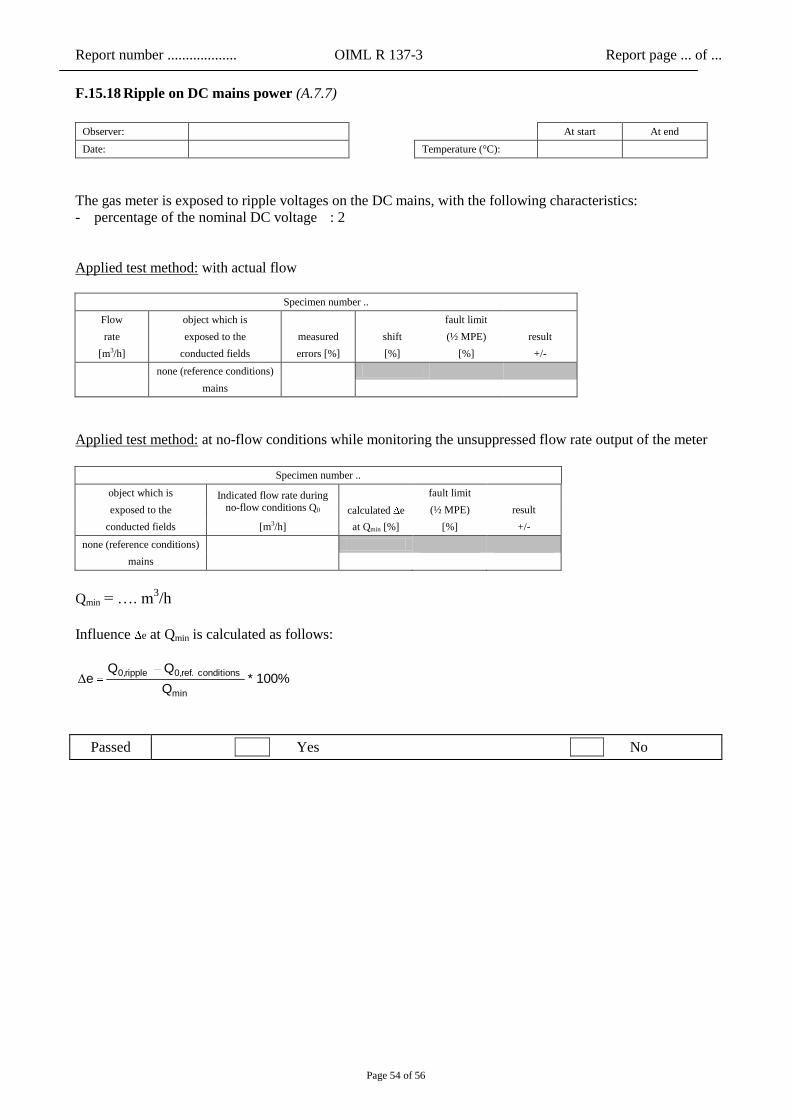
F.15.18 Ripple on DC mains power (A.7.7)
Observer: At start At end
Date: Temperature (°C):
The gas meter is exposed to ripple voltages on the DC mains, with the following characteristics:
- percentage of the nominal DC voltage : 2
Applied test method: with actual flow
Specimen number ..
Flow object which is fault limit
rate exposed to the measured shift (½ MPE) result
[m3/h] conducted fields errors [%] [%] [%] +/-
none (reference conditions)
mains
Applied test method: at no-flow conditions while monitoring the unsuppressed flow rate output of the meter
Specimen number ..
object which is Indicated flow rate during no-flow conditions Q0
fault limit
exposed to the calculated e (½ MPE) result
conducted fields [m3/h] at Qmin [%] [%] +/-
none (reference conditions)
mains
Qmin = …. m3/h
Influence e at Qmin is calculated as follows:
100% * Q
Q Q e
min
conditions ref.0,ripple0,Δ
Passed Yes No
Report number ................... OIML R 137-3 Report page ... of ...
Page 55 of 56
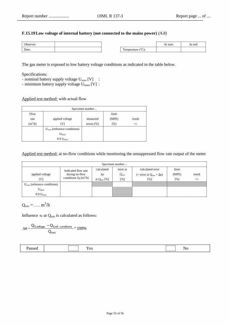
F.15.19 Low voltage of internal battery (not connected to the mains power) (A.8)
Observer: At start At end
Date: Temperature (°C):
The gas meter is exposed to low battery voltage conditions as indicated in the table below.
Specifications:
- nominal battery supply voltage Unom [V] :
- minimum battery supply voltage Ubmin [V] :
Applied test method: with actual flow
Specimen number ..
Flow
limit
rate applied voltage measured (MPE) result
[m3/h] [V] errors [%] [%] +/-
Unom (reference conditions)
Ubmin
0.9 Ubmin
Applied test method: at no-flow conditions while monitoring the unsuppressed flow rate output of the meter
Specimen number ..
Indicated flow rate
during no-flow
conditions Q0 [m3/h]
calculated error at calculated error limit
applied voltage e Qmin (= error at Qmin + e) (MPE) result
[V] at Qmin [%] [%] [%] [%] +/-
Unom (reference conditions)
Ubmin
0.9 Ubmin
Qmin = …. m3/h
Influence e at Qmin is calculated as follows:
100% * Q
Q Q e
min
conditions ref.0,voltage0,Δ
Passed Yes No
Report number ................... OIML R 137-3 Report page ... of ...
Page 56 of 56
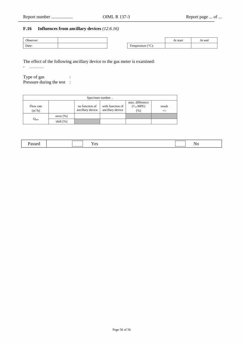
F.16 Influences from ancillary devices (12.6.16)
Observer: At start At end
Date: Temperature (°C):
The effect of the following ancillary device to the gas meter is examined:
- ……….
Type of gas :
Pressure during the test :
Specimen number ..
Flow rate
no function of with function of
max. difference
(¹/10 MPE) result
[m3/h] ancillary device ancillary device [%] +/-
Qmin error [%]
shift [%]
Passed Yes No