reference for development - durham, nc
TRANSCRIPT

City of Durham Reference Guide for Development 2021‐07‐23 Page 1
Reference Guide for
Development
07-23-2021

City of Durham Reference Guide for Development 2021‐07‐23 Page 2
Contents Directory ............................................................................................................................................................ 6
Introduction ........................................................................................................................................................ 8
Alternatives Application Procedures ................................................................................................................. 9
Section 1: Development Review Group’s Role in the Durham City-County Planning Review Process ......... 13
1.1 Engineering Division’s Role and Submittal Requirements .................................................................... 13
1.2 Stormwater Services Division’s Role and Submittal Requirements ...................................................... 19
1.3 Department of Transportation’s Role and Submittal Requirements ...................................................... 30
Section 2: City of Durham Construction Drawing Review and Construction Process .................................... 34
2.1 Review Group’s Role in the Construction Drawing Review Process .................................................... 34
2.2 When Are Construction Drawings Required? ........................................................................................ 35
2.3 Construction Drawing Approval Process ............................................................................................... 36
2.4 Construction Drawing Checklist ............................................................................................................. 38
2.5 Construction Drawing Profiles Checklist................................................................................................ 41
2.6 Construction Permitting ......................................................................................................................... 46
2.7 Construction Phase ............................................................................................................................... 52
Section 3: Other Permits ................................................................................................................................. 56
3.1 Building Permit ....................................................................................................................................... 56
3.2 Moving and Demolition Permit ............................................................................................................... 56
3.3 Construction on City ROW/Private Property Permit .............................................................................. 56
3.4 License or Encroachment Agreements ................................................................................................. 58
3.5 Other Utility Permits ............................................................................................................................... 58
3.6 Soil and Erosion Control (Grading Permit) ............................................................................................ 59
3.7 Wetlands ................................................................................................................................................ 59
3.8 Right of Way Utility Excavation Permit .................................................................................................. 60
3.9 Signalized Intersections ......................................................................................................................... 60
Section 4.0: City of Durham As-built Drawings Review Process .................................................................... 61
4.0.1 When are As-built Drawings Required? ............................................................................................. 61
4.0.2 As-built Review Process ..................................................................................................................... 61
4.0.3 As-built Drawings Checklist ................................................................................................................ 62
4.0.4 Electronic Submittal Requirements .................................................................................................... 64
4.0.5 Approved As-built Drawings Submittal ............................................................................................... 71
Section 4.1: City of Durham Video Inspection Submittal and Review Process .............................................. 73
4.1.1 When is Video Inspection Required? ................................................................................................. 73
4.1.2 Video Inspection Review Process ...................................................................................................... 73
4.1.3 Video Inspection Review Fees ........................................................................................................... 74
4.1.4 Video Inspection Submittal Requirements ......................................................................................... 75

City of Durham Reference Guide for Development 2021‐07‐23 Page 3
Section 5.0: Water Supply/Distribution ............................................................................................................ 76
5.1 Sizing of Water Mains ............................................................................................................................ 76
5.2 Water Main Location .............................................................................................................................. 78
5.4 Fire Hydrants ......................................................................................................................................... 80
5.5 Fire Department Connections (FDC) ..................................................................................................... 81
5.6 Valves .................................................................................................................................................... 81
5.7 Blow-offs ................................................................................................................................................ 83
5.8 Pressure-reducing Valves ..................................................................................................................... 83
5.9 Services and Meters .............................................................................................................................. 83
5.10 Water System Abandonment ............................................................................................................... 84
Section 6.0: Cross Connection Control ........................................................................................................... 85
6.1 Guidelines .............................................................................................................................................. 85
6.2 Facilities that Require Installation of a Backflow Preventer .................................................................. 86
6.3 Approved Backflow Prevention Assemblies .......................................................................................... 87
6.4 Backflow Prevention Assembly Installation ........................................................................................... 87
6.5 Fire Hydrants ......................................................................................................................................... 87
6.6 Lawn Irrigation ....................................................................................................................................... 87
6.7 MEP Drawings ....................................................................................................................................... 87
6.8 Fee Schedule ......................................................................................................................................... 87
Section 7.0: Sanitary Sewer System ............................................................................................................... 88
7.1 General .................................................................................................................................................. 88
7.2 Sizing of Sanitary Sewer Mains ............................................................................................................. 88
7.3 Sanitary Sewer Line Location ................................................................................................................ 89
7.4 Manholes ............................................................................................................................................... 91
7.5 Sewer Taps ............................................................................................................................................ 92
7.6 Anchors .................................................................................................................................................. 92
7.7 Creek Crossings (Aerial) ....................................................................................................................... 92
7.8 Services ................................................................................................................................................. 93
7.9 Force Mains ........................................................................................................................................... 93
7.10 Pump Stations ..................................................................................................................................... 94
7.11 Sanitary Sewer Abandonment ............................................................................................................. 94
Section 8.0: Stormwater Conveyance Systems .............................................................................................. 95
8.0.1 Land Disturbance................................................................................................................................ 95
8.0.2 Design Criteria .................................................................................................................................... 95
8.0.3 Storm Drainage ................................................................................................................................... 98
8.0.4 Culverts ............................................................................................................................................... 99
8.0.5 Open Channels ................................................................................................................................... 99
City of Durham Reference Guide for Development 2021‐07‐23 Page 4
8.0.6 Gutter Spread ................................................................................................................................... 100
8.0.7 Stormwater Conveyance Materials and Installation Standards ........................................................ 101
8.0.8 Stormwater Easements and Building Setbacks ............................................................................... 103
8.0.9 Retaining Walls ................................................................................................................................. 106
Section 8.1: Stormwater Impact Analysis ...................................................................................................... 108
8.1.1 General ............................................................................................................................................. 108
8.1.2 SIA Narrative .................................................................................................................................... 114
8.1.3 Peak Flow Analysis .......................................................................................................................... 116
8.1.4 Pollutant Removal Requirements ..................................................................................................... 129
8.1.5 Potential SCM Location Issues ......................................................................................................... 138
8.1.6 Diffuse Flow into a Riparian Buffer ................................................................................................... 140
Section 8.2: Supplemental Stormwater Development Requirements ........................................................... 142
8.2.1 Provisions for Declaration for Covenants, Conditions & Restrictions ............................................... 142
8.2.2 SCM Permitting Process .................................................................................................................. 145
Section 8.3: Stormwater Control Measures .................................................................................................. 156
8.3.1 General ............................................................................................................................................. 156
Section 8.4: Stormwater SCM Design Summaries ....................................................................................... 158
Dry Detention Basin Design Summary ...................................................................................................... 159
Wet Detention Pond Design Summary ...................................................................................................... 162
Sand Filter Design Summary ..................................................................................................................... 166
Bio-Retention Area Design Summary ........................................................................................................ 168
Constructed Wetland and Pocket Wetland Design Summary ................................................................... 171
Underground Detention Design Summary................................................................................................. 175
Section 8.5: ................................................................................................................................................... 178
Section 8.6: As-built Certification Requirements for SCMs in the City of Durham ........................................ 179
8.6.1 As-built Program Description ............................................................................................................ 179
8.6.2 Critical Components of SCMs .......................................................................................................... 185
8.6.3 Vegetation Establishment ................................................................................................................. 187
8.6.4 Certification Forms and Documents ................................................................................................. 188
General As-Built and Construction Certification ........................................................................................ 190
Geotechnical Certification for Dams and Seepage Controls ..................................................................... 193
Materials Certification for SCMs with Filter Media (except Filterras® and StormFilters®)........................ 194
Dry Ponds, Wet Ponds, Constructed Wetlands, and Pocket Wetlands .................................................... 195
Open Sand Filters ...................................................................................................................................... 199
Closed Sand Filters ................................................................................................................................... 203
Underground Detention Systems .............................................................................................................. 207
Closed Sand Filter with Underground Detention ....................................................................................... 210
City of Durham Reference Guide for Development 2021‐07‐23 Page 5
Bioretention Areas ..................................................................................................................................... 214
Level Spreader-Vegetated Filter Strip Systems ........................................................................................ 218
Vegetated Water Quality Swales ............................................................................................................... 221
Rainwater Harvesting Systems ................................................................................................................. 223
Permeable Pavement ................................................................................................................................ 225
Filterra® Units ............................................................................................................................................ 229
StormFilter® by Contech ........................................................................................................................... 231
Silva Cell Suspended Pavement with Bioretention ................................................................................... 234
Section 9: Streets .......................................................................................................................................... 237
9.1 Street Design ....................................................................................................................................... 237
9.2 Pavement Design ................................................................................................................................ 240
9.3 Curve Design ....................................................................................................................................... 241
9.4 Driveways, Private Drives and Private Access & Common Areas ...................................................... 241
9.5 Sidewalks ............................................................................................................................................. 242
9.6 Street Signage ..................................................................................................................................... 243
9.7 Construction ......................................................................................................................................... 243
9.8 Street Widening ................................................................................................................................... 244
9.9 Storm Drainage .................................................................................................................................... 244
Section 10: Transportation ............................................................................................................................ 245
Section 10.1 Layout ................................................................................................................................... 245
Section 10.2 Signage and Pavement Marking Requirements ................................................................... 246
10.3 Traffic Impact Analysis Requirements ............................................................................................... 248
Section 11: Standard Notes .......................................................................................................................... 258
11.1 Engineering Section Notes ................................................................................................................ 258
11.2 Stormwater Services Notes ............................................................................................................... 262
11.3 Department of Transportation Notes ................................................................................................. 265
Section 12: Forms ......................................................................................................................................... 268
Section 13: Development Fees ..................................................................................................................... 269
13.1 Water and Sanitary Sewer Charges .................................................................................................. 269
13.2 Other Permits and Fees .................................................................................................................... 272
APPENDIX A: Procedure for Obtaining a Copy of the Published NRCS Soil Surveys for NC ..................... 275
City of Durham Reference Guide for Development 2021‐07‐23 Page 6
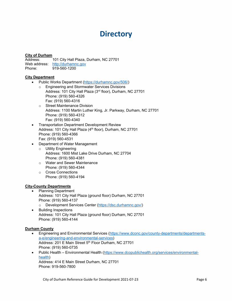
Directory
City of Durham Address: 101 City Hall Plaza, Durham, NC 27701 Web address: http://durhamnc.gov Phone: 919-560-1200 City Department
Public Works Department (https://durhamnc.gov/506/) o Engineering and Stormwater Services Divisions
Address: 101 City Hall Plaza (3rd floor), Durham, NC 27701 Phone: (919) 560-4326 Fax: (919) 560-4316
o Street Maintenance Division Address: 1100 Martin Luther King, Jr. Parkway, Durham, NC 27701 Phone: (919) 560-4312 Fax: (919) 560-4340
Transportation Department Development Review Address: 101 City Hall Plaza (4th floor), Durham, NC 27701 Phone: (919) 560-4366 Fax: (919) 560-4531
Department of Water Management o Utility Engineering
Address: 1600 Mist Lake Drive Durham, NC 27704 Phone: (919) 560-4381
o Water and Sewer Maintenance Phone: (919) 560-4344
o Cross Connections Phone: (919) 560-4194
City-County Departments Planning Department
Address: 101 City Hall Plaza (ground floor) Durham, NC 27701 Phone: (919) 560-4137 o Development Services Center (https://dsc.durhamnc.gov/)
Building Inspections Address: 101 City Hall Plaza (ground floor) Durham, NC 27701 Phone: (919) 560-4144
Durham County Engineering and Environmental Services (https://www.dconc.gov/county-departments/departments-
a-e/engineering-and-environmental-services) Address: 201 E Main Street 5th Floor Durham, NC 27701 Phone: (919) 560-0735
Public Health – Environmental Health (https://www.dcopublichealth.org/services/environmental-health) Address: 414 E Main Street Durham, NC 27701 Phone: 919-560-7800
City of Durham Reference Guide for Development 2021‐07‐23 Page 7
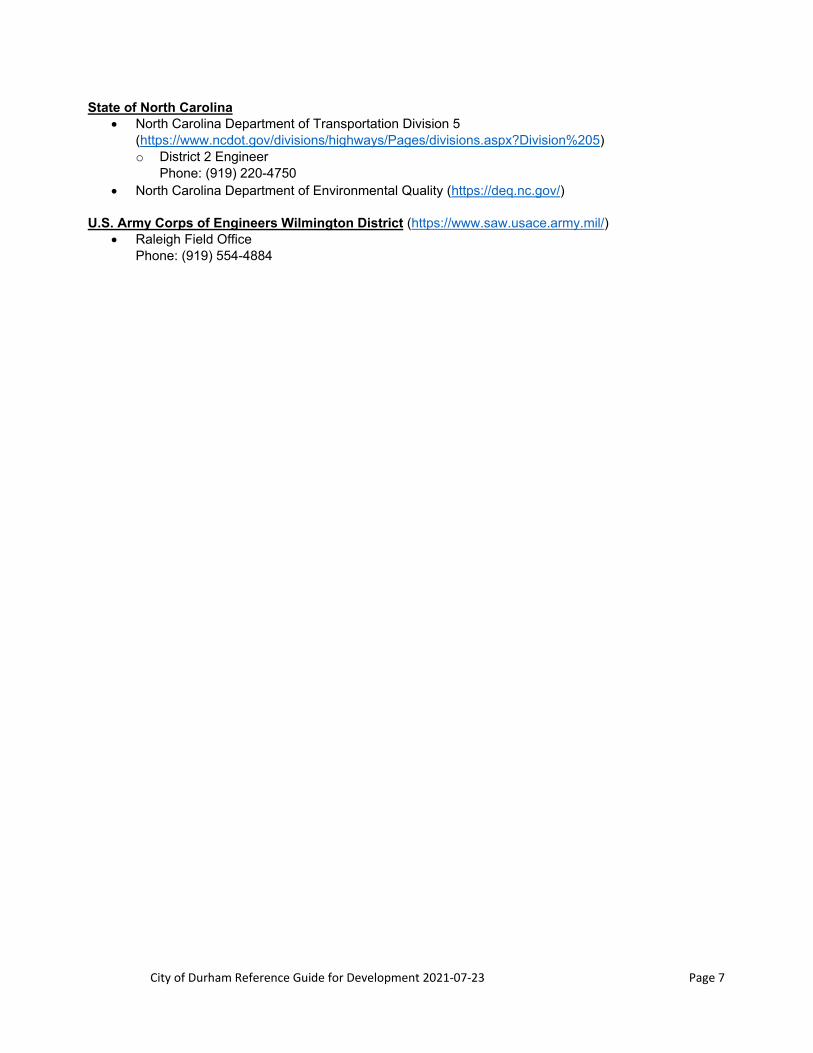
State of North Carolina North Carolina Department of Transportation Division 5
(https://www.ncdot.gov/divisions/highways/Pages/divisions.aspx?Division%205) o District 2 Engineer
Phone: (919) 220-4750 North Carolina Department of Environmental Quality (https://deq.nc.gov/)
U.S. Army Corps of Engineers Wilmington District (https://www.saw.usace.army.mil/) Raleigh Field Office
Phone: (919) 554-4884

City of Durham Reference Guide for Development 2021‐07‐23 Page 8
Introduction
The City of Durham Development Review Process encompasses multiple plan submittals and permit applications to different City departments. The City of Durham Public Works Department Engineering Division and Stormwater Services & GIS Division, the Department of Transportation Development Review and the Department of Water Management Development Review Groups have prepared this guide to explain their involvement in the City’s Development Review Process and to provide a reference manual of some of the City’s design standards and design requirements. Please contact the Development Services Center ([email protected]) for more information about the City’s review process and the City’s Unified Development Ordinance (UDO). Also consult the City’s Code of Ordinances.
Appealing Interpretations of this Document
An appeal of a staff’s application of a standard set by the Reference Guide for Development to a particular development application should initially be made to the Director of the City Department applying the standard. If further action is desired after a decision is made by a Department Director, the appeal may be escalated to the City Manager’s Office. A decision made by the City Manager’s Office shall be final. A request to vary from standards set in this Reference Guide may be initiated by following the steps outlined in the Alternatives Application Procedures found on page 9 of this document.

City of Durham Reference Guide for Development 2021‐07‐23 Page 9
Alternatives Application Procedures
1.0 Intent
A. Any and all Development should be constructed pursuant to the requirements of the RGD. However, rare circumstances may arise in which it is preferable for the developer that the requirements of the RGD to be varied. Consequently, when an owner, contractor, or designer proposes to use a different method of design, construction, equipment, or materials from that which is specified by the RGD, an “Alternate Material, Design or Methods” application (“RGD Alternatives Application”) shall be submitted to the City of Durham Development Services Center (DSC). The DSC will then assign requests to the appropriate City department in charge of the operations of the aspect of the project in which the variance is being requested.
B. The City will not permit construction to a lesser standard than that which is required by the requirements of the RGD. However, the City will evaluate an RGD Alternatives Application to determine if the proposed alternative material, design, or method provides, at minimum, the equivalent level of protection for quality, strength, effectiveness, durability, maintainability, and protection of public and environmental health, safety, and welfare as required by the intent of the RGD. Approval of an RGD Alternatives Application by the City is not intended to represent a “variance” from or a lessening of the minimum standards required by the RGD.
C. The City may consider and/or approve a preferable but lesser alternative to standards set in the RGD if field conditions render the RGD standard impossible, and if the developer has already exhausted alternative options. A developer requesting a variance for this reason should provide documentation of unsuccessful attempts to use alternative methods to rectify the situation.
D. Note that the City does not have the authority to waive minimum requirements as defined in State Statutes and that the City will continue to adhere to the requirements set by all applicable State Statutes in all decisions and processes related to development and construction. When State Statute defines minimum requirements, an appeal to the State must be made prior to any appeal to the City for variance. State approval must be granted and furnished to City staff before City staff can begin any process to consider variance.
E. Note that this process is intended to facilitate a decision-making process for considering alternatives to standards set in the RGD and to provide a process by which requestors can appeal staff decisions regarding requested alternatives. Any other requests related to City of Durham development standards should be resolved with applicable City staff.
2.0 Information required as part of an RGD Alternatives Application
The applicant should provide the following information in writing, along with any other documentation requested by the City to document the equivalent or superior level of quality, strength, effectiveness, durability, maintainability, and protection of public and environmental health, safety, and welfare, is provided by the proposed RGD Alternative.
A. General Information Required
1. Identify the project name, date of request, and project site/street address/lot number/parcel ID. Provide the name of the owner, designer of record and contractor (if applicable) and the contact person for each entity, including their telephone number(s), fax number, email address and mailing address.

City of Durham Reference Guide for Development 2021‐07‐23 Page 10
2. If the applicant is not the owner, designer of record or the contractor, identify the applicant’s association with the project and provide the telephone number(s), fax number, email address and mailing address.
3. The City may require additional information specific to the project, such as development permit type, tract and lot number, etc., and/or other documentation as required before evaluating the RGD alternative.
4. Designs and other applicable reports per State Statute must be signed and sealed by an accredited engineer working within their area of expertise.
B. Submittal Information
1. Reference Guide for Development Alternative Request Application (https://durhamnc.gov/DocumentCenter/View/32708/)
2. Describe the proposed RGD alternative.
3. Identify the RGD section(s) for which the alternative is being requested.
4. Describe why the applicant is seeking the proposed RGD Alternative.
5. Explain how the proposal provides an equivalent or superior level of quality, strength, effectiveness, durability, maintainability, and protection of public health, safety, and welfare as the RGD requirement
6. Provide a set of project drawings, specifications and any other construction documents necessary to evaluate the request.
7. All construction/building data relevant to the request should be provided.
C. Documentation that may accompany request
1. As proof of compliance, Designated City Staff may require tests, test reports, and/or specific analysis that are specified in the State Building code or the RGD.
2. Other required documentation may include manufacturer’s information (details/cut sheets, shop drawings, installation requirements, specifications, etc.), calculations, MSDS sheets, verification of installer credentials, and/or other information as required by Designated City Staff for review to confirm compliance.
3. In addition, a product may require special inspection to verify proper installation. Decisions on special inspections rest solely with Designated City Staff and the cost of any special inspections shall be borne solely by the applicant.
4. Specific tests may not be listed in the State Building code or RGD, particularly for some innovative methodologies. In the absence of recognized and accepted test methods, Designated City Staff can specify and approve what test(s) are appropriate to confirm compliance. Testing reports shall be submitted to Designated City Staff for consideration.
City staff reserves the right to request additional information that is not included in the above list.

City of Durham Reference Guide for Development 2021‐07‐23 Page 11
D. Cost
1. All testing and analyses required to approve an RGD alternative shall be paid for by the applicant and not the City.
2. If the City of Durham does not have the expertise on staff to make a thorough and competent review of the request, a third party review process may be utilized. Any cost associated with a third party review shall be paid by the applicant, and the suitable and appropriate third party to be utilized will be selected by City of Durham staff.
3. Submission of an application for consideration of an alternative to RGD standards are assigned a fee to be paid to the applicable City department. The fee amount shall be determined using the following matrix:
i. Tier 1 Alternative - $1500 fee
a. A Tier 1 Alternative is defined as one that does not significantly impact design or construction, does not necessitate changes to City processes, may be approved by City staff with conditions, and requires analysis from multiple staff members. A Tier 1 Alternative is defined as one that is estimated by staff to require between 4 and 20 hours of staff review time.
Examples include: proposal of an alternative building material, requests to forego construction of a minor traffic feature, installation of a sidewalk or obstruction outside of the right of way and/or in drainage easements, request to utilize an alternative component, requests to vary from minor design features, requests to vary from slope degree, or pipe length, etc.
ii. Tier 2 Alternative - $4000 fee
a. A Tier 2 Alternative is defined as one that significantly impacts design, construction, or future maintenance of the infrastructure in question, or the surrounding property. In addition, it may require changes to City processes, such as inspections and/or maintenance. A Tier 2 Alternative is defined as one that is estimated by staff to require 21 or more hours of staff review time.
Examples include: Request to utilize proprietary technology, request to utilize a type of SCM not currently approved by the City, request to use an alternate design standard, requests pertaining to lift stations, (major requests) to allow non-standard construction in rights of way, reduction of street dimensions, etc.
iii. It should be noted that there exists the possibility that an Alternatives application may not incur a fee if it can be determined that the alternative being requested will require less than a significant amount of staff time to review (less than a few hours), if the alternative being requested is anticipated to not have the potential to negatively impact future maintenance construction or design, or if the alternative is being requested during the construction process in response to a minor change in field conditions. These requests do not require the submission of an application or a fee unless a requestor wishes to appeal City staff’s decision. If a requestor wishes to appeal staff decision on such an alternatives request, the requestor must submit their request as a Tier 1 or 2 Alternative request as determined by staff, accompanied by the appropriate application and fee. The applicant may then appeal the staff decision using the appeal process outlined elsewhere in this document.
Examples of this type of alternatives request include:
City of Durham Reference Guide for Development 2021‐07‐23 Page 12
Cutting tree branches up for sight distance triangles. Unmanned drone aerial pictures and surveys within the right of way. Low hazard right of way plantings (ground cover to non-woody vegetation). Driveway shifts or minor width issues. Curb and gutter transitions to various obstructions. Decorative landscaping self-supporting walls on private property that do not require a
building permit. Retrofitting an on-grade inlet for a roll grate and repairing curb and gutter. Looking at shifting a catch basin, inlet, or fire hydrants for existing conditions a few feet
in either direction. Modifying submittal drawing scale requirements due to size of property Negligible increases in peak flow requirements
3.0 Results
A. An RGD alternative application can be approved or denied or can be approved with conditions by Designated City Staff. Regardless of the outcome, the decision shall only apply to the specific project for which the proposed alternate was submitted. If conditions or the design changes during the course of the project, a new RGD alternative application must be submitted to Designated City Staff for approval.
B. City staff reserves the right to reject and/or deny an application on the basis of missing information and/or an incomplete submission packet where the applicant has not taken action to complete the packet on City staff request.
C. Approval or denial or approved with conditions by Designated City Staff shall be issued in writing to the applicant.
A decision made by Designated City Staff may be appealed through the submission of an appeal to the City Manager’s Office. The City Manager’s Office will review the documentation submitted by the applicant as part of the RGD alternative application and Staff’s written denial and the basis for the denial. The Manager’s Office’s determination regarding an appeal shall be final. A signed determination by the City Manager and/or appointed designee shall be furnished to the applicant after a decision has been made. A “Yes” decision made by City Management after an initial rejection by City departmental staff must be signed and sealed by a third party engineering firm prior to return to the applicant. Said engineering firm will be furnished by the applicant and must be approved by Designated City Staff.
This Document does not imply that Designated City Staff must approve any material, design, or method not specified in the RGD.

City of Durham Reference Guide for Development 2021‐07‐23 Page 13
Section 1: Development Review Group’s Role in the
Durham City‐County Planning Review Process
The following is an overview of the roles and requirements of the Public Works Engineering Division and Stormwater Services Division and the Department of Transportation Development Review Groups in the Planning approval process. Consult the Unified Development Ordinance (UDO) for more information about rezonings, site plans, preliminary plats and final plats requirements. Applications, correspondences and plan submittals must always be directed to the City-County Planning Department (919-560-4137) at the Development Services Center (https://dsc.durhamnc.gov/264/Application-guide). Status and comments of applications can be checked in the City’s website through the Land Development Office portal located here: https://ldo4.durhamnc.gov/DurhamWeb/.
1.1 Engineering Division’s Role and Submittal Requirements
A. Contact Information
The Engineering Development Review Group is located on the 3rd floor of City Hall and can be reached at (919) 560-4326 and fax number (919) 560-4316. Correspondence can be sent to:
Public Works Department Engineering Development Review Group
101 City Hall Plaza Suite 3100 Durham, NC 27701
B. Engineering Development Review Group Role
1. Rezonings, Site Plans, and Preliminary Plats
The Engineering Development Review Group is tasked with reviewing rezonings (with or without annexations/extension agreements), site plans, and preliminary plats applications as they relate to the following:
Public and private road standards (curve standards and street and pavement sections) Sidewalk and curb ramps (PROWAG) Water system Fire protection system Sanitary sewer system Stormwater drainage and conveyance systems
2. Final Plats
The Engineering Development Review Group is tasked with reviewing the following items in final plats applications:
Roadway right of way Water systems and easements Storm drainage conveyance systems and easements

City of Durham Reference Guide for Development 2021‐07‐23 Page 14
Sanitary sewer systems and easements Plat matches the approved construction drawings Request of construction security for infrastructure not completed
Construction drawings shall be approved prior to approval of the final plat. See Section 2 for information about the construction drawing review process.
Per UDO requirements, prior to final plat approval all public infrastructure and private streets built to City public street standards (collectively “Infrastructure”) must be constructed or a performance guarantee acceptable to the City Public Works Department must be provided. If submittal of a performance guarantee is desired, submit a signed and sealed construction cost estimate for completion of the incomplete Infrastructure pursuant to the approved construction drawings. Engineering will determine the performance guarantee amount for the incomplete Infrastructure. See Section 2 and Build it or Bond it for more information on Engineering’s Construction Security Policy.
C. Submittal Requirements (Checklists)
The Engineering Division’s checklists contain the minimum requirements for Planning submittals. These checklists shall be used as a guide prior to submitting any Site Plan, Preliminary Plat, or Final Plat. The Site Plan and Preliminary Plat Checklist and the Final Plat Checklist are not required to be submitted with the plans. The checklists are located online and below. Check with the City-County Planning Department for additional applications required during submittal.

City of Durham Reference Guide for Development 2021‐07‐23 Page 15
CITY OF DURHAM – ENGINEERING SITE PLAN AND PRELIMINARY PLAT CHECKLIST
Department of Public Works 101 City Hall Plaza | Durham, NC 27701 919.560.4326 | F 919.560.4316
www.durhamnc.gov
The following is a list of site plan and preliminary plat requirements from the Engineering Division. This list is intended to give general guidelines only and is not to be considered all-inclusive. Obtain a Summary Utilities Development Statement from the Department of Water Management before submitting the site plan: https://durhamnc.gov/FormCenter/Water-Management-16/Required-Utilities-Statement-Application-173.
1. Cover Sheet
a) Provide sheet index b) Add Engineering standard notes in the Public Works Conditions of Approval box (see Planning Checklist
or Section 11 of Reference Guide)
2. Existing Conditions and Demolition Plan
a) Show all property boundaries with linear bearings and distances, curve boundary information (table format – curve number, radii, length, delta angle, chord bearing and chord distance) and the building setbacks. State the source of the provided boundary information.
b) Label existing property lines which are to be removed as “Hereby removed”. c) Show all buildings and structures and label current use/facility name and finished floor elevation. d) Show all pavement, parking and driveway access points on the property. e) Show all walkways/sidewalks/curb ramps both adjacent to the development and opposite any existing
roadways or intersections. f) Show all adjoining and opposing streets and alleys with names, rights-of-way and pavement widths,
state route numbers. Label all roads as “Public” or “Private” and note any unopened rights-of-way. Show and label all existing features and improvements such as driveways, sidewalk, hydrants, light poles, etc.
g) Show and label (size, material, and inverts) all existing utilities within the right-of-way and the project site: i. Water lines, valves, hydrants (within 500 feet of the site), fire department connections, water
services, water meters and vaults, and backflow preventers ii. Sanitary sewer lines, manholes, sanitary sewer services, cleanouts, force mains, and pump stations iii. Storm sewer pipes, catch basins, headwalls, junction boxes, other structures, ditches and swales
b) Provide abandonment notes for water and sanitary sewer services which are being abandoned. c) Show and label all easements, both public and private with location and width. Define all easements by
centerline bearings, distances and ties to property corners or page book and deed reference. d) Show all topography with a maximum of two-foot contour intervals for the development. Provide notes
that indicate references to any permanent benchmarks, accepted datum, and source data. Durham topography maps may be used but it is recommended to obtain field topography.
3. Site Plan Sheet
a) Show all areas to be dedicated or reserved for public or private use and define with property lines or easements.
b) Show proposed roadways and label pavement and right-of-way widths. Also label as ‘Public’ or ‘Private’. c) Provide typical roadway cross-sections for all proposed public and/or private streets/alleys. Include the
size of curbing, shoulders, sidewalks, pavement widths and rights-of-way widths. d) Provide new street centerline radius. e) Show and label new parking areas and proposed driveways with radii and width.

City of Durham Reference Guide for Development 2021‐07‐23 Page 16
f) For townhome developments proposing Private Access/Common Area, label drives that do not meet City nor NCDOT standards as Private Access and Common Areas and provide standard note about private maintenance for these areas and that the City will never take these drives over for maintenance.
g) Show and label proposed sidewalks and curb ramps. h) Provide water valve, manhole, and temporary turn-around at all phase lines.
4. Grading Plan Sheet
a) Provide storm drainage system layout. Do not provide proposed sizes as these will be reviewed during construction drawing review.
b) Provide preliminary storm drainage easement sizes, setbacks, and locations. c) Label all retaining walls with preliminary top of wall and bottom of wall elevations. d) Provide overland relief for all stormwater pipe systems, inlets, and culverts such that no building or
habitable structure will be flooded or have water impounded against it during the 100-year storm event.
5. Utility Plan Sheet
a) Show and label all proposed water and sanitary sewer lines. Do not provide proposed sizes as these will be reviewed during construction drawing review.
b) Show and label all proposed utility easements and utility easement setbacks per the Reference Guide for Development.
c) Show and label all proposed valves, manholes, services, sanitary sewer cleanouts, hydrants, meters with sizes, fire department connection, backflow preventers, dumpster drains and grease traps.
d) Label utilities as public or private. Label utilities within a Private Access/Common Area as private. e) Extend sewer to property lines for future service of adjacent parcels. f) Provide second waterline feed for projects of 100 units or more.
6. Landscape Plan Sheet
a) Show and label all easements and ensure that landscaping is kept outside of the easements and the public rights-of-way.
b) Show existing and proposed water, sanitary sewer and storm drainage systems to ensure that there are no conflicts with the proposed landscaping.
c) Trees shall be at least 5 feet from utilities.
City of Durham Reference Guide for Development 2021‐07‐23 Page 17
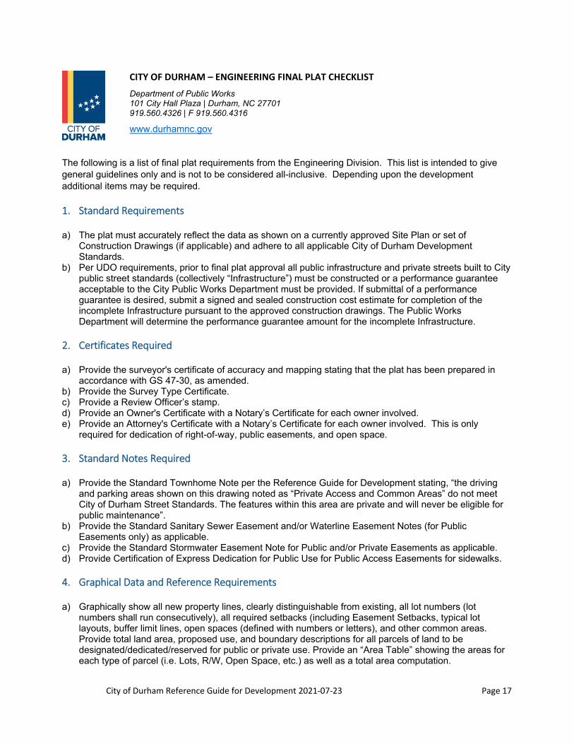
CITY OF DURHAM – ENGINEERING FINAL PLAT CHECKLIST
Department of Public Works 101 City Hall Plaza | Durham, NC 27701 919.560.4326 | F 919.560.4316
www.durhamnc.gov
The following is a list of final plat requirements from the Engineering Division. This list is intended to give general guidelines only and is not to be considered all-inclusive. Depending upon the development additional items may be required.
1. Standard Requirements
a) The plat must accurately reflect the data as shown on a currently approved Site Plan or set of Construction Drawings (if applicable) and adhere to all applicable City of Durham Development Standards.
b) Per UDO requirements, prior to final plat approval all public infrastructure and private streets built to City public street standards (collectively “Infrastructure”) must be constructed or a performance guarantee acceptable to the City Public Works Department must be provided. If submittal of a performance guarantee is desired, submit a signed and sealed construction cost estimate for completion of the incomplete Infrastructure pursuant to the approved construction drawings. The Public Works Department will determine the performance guarantee amount for the incomplete Infrastructure.
2. Certificates Required
a) Provide the surveyor's certificate of accuracy and mapping stating that the plat has been prepared in accordance with GS 47-30, as amended.
b) Provide the Survey Type Certificate. c) Provide a Review Officer’s stamp. d) Provide an Owner's Certificate with a Notary’s Certificate for each owner involved. e) Provide an Attorney's Certificate with a Notary’s Certificate for each owner involved. This is only
required for dedication of right-of-way, public easements, and open space.
3. Standard Notes Required
a) Provide the Standard Townhome Note per the Reference Guide for Development stating, “the driving and parking areas shown on this drawing noted as “Private Access and Common Areas” do not meet City of Durham Street Standards. The features within this area are private and will never be eligible for public maintenance”.
b) Provide the Standard Sanitary Sewer Easement and/or Waterline Easement Notes (for Public Easements only) as applicable.
c) Provide the Standard Stormwater Easement Note for Public and/or Private Easements as applicable. d) Provide Certification of Express Dedication for Public Use for Public Access Easements for sidewalks.
4. Graphical Data and Reference Requirements
a) Graphically show all new property lines, clearly distinguishable from existing, all lot numbers (lot numbers shall run consecutively), all required setbacks (including Easement Setbacks, typical lot layouts, buffer limit lines, open spaces (defined with numbers or letters), and other common areas. Provide total land area, proposed use, and boundary descriptions for all parcels of land to be designated/dedicated/reserved for public or private use. Provide an “Area Table” showing the areas for each type of parcel (i.e. Lots, R/W, Open Space, etc.) as well as a total area computation.
City of Durham Reference Guide for Development 2021‐07‐23 Page 18
b) When subdividing or recombining property, graphically show all property lines to be removed, clearly distinguishable from property lines to remain. Provide data for all property lines or portions of property lines to be removed and label them as “Hereby Removed”.
c) Provide bearing, distance, and curve data for all lot and boundary lines. Linear dimensions shall be expressed in feet and decimals of a foot and all angular measurements shall be expressed by bearings.
d) All curves shall be defined by radius, central angle (delta), tangent, arc, chord distances, and chord bearings. All curve data shall be shown in Curve Tables.
e) All line segments and curves listed in Line Segment and Curve Tables shall be shown in the appropriate locations on the plat, designated by L-# or C-#, and they shall be numbered consecutively throughout all Sheets of the plat. (i.e. do not begin renumbering on each Sheet).
f) Graphically show and appropriately label all “Proposed” alley lines, building setbacks, cemeteries, utility, storm drainage, greenway, and other easements. Define all “Proposed” easements with either boundary data or centerline data, and ties to property corners. (This applies to both Public and Private Easements).
g) Graphically show and appropriately label all “Existing” alley lines, building lines, cemeteries, utility, storm drainage, greenway, and other easements. Define all “Existing” easements with PB/PG and/or DB/PG references and centerline or boundary ties to property corners. If no existing references are available or if the easements have been resurveyed, define them with centerline or boundary data and ties to property corners. (This applies to both Public and Private Easements).
h) Graphically show the angle of departure of all adjoining property and right-of-way lines. i) Provide the names of all adjoining property owners with deed and/or plat book references and Pin and
Parcel ID numbers. If applicable, provide existing adjoining Lot numbers with the existing subdivision name and references.
j) Graphically show all street rights-of-way within or adjoining the property and label them with the street name (and SR Number if applicable), right-of-way width, “Public” or “Private”, and “Existing” or “Hereby Dedicated”. If available, provide the DB and/or PB references for all “Existing” rights-of-way.
k) Where available within 2000’, provide a precise tie (with bearing, distance, co-ordinate sets, and appropriate N.C. Grid Datum labels), between one or more prominent points on the exterior boundary of the property and a N.C. Grid Monument. If no monument is available within 2000’, add a note to the plat stating such, and provide bearing and distance ties, along with appropriate PB/PG references to the existing recorded plat used as the source to establish the plat bearings. NC grid coordinates can also be derived from GPS observations that are processed by OPUS. This does not apply to exempt plats (see Planning Checklist for requirements of Exempt Plats).
l) Label two or more permanent “Control Corners” on the plat. This does not apply to exempt plats (see Planning Checklist for requirements of Exempt Plats).
m) Acquire the addresses from the City of Durham for all lots or parcels and show them on the plat.
5. Additional Requirements for Plats with Multiple Sheets
a) Provide an overall Index Map with a North Arrow, Lot Numbers, Street Names, Matchlines, and Sheet Numbers, defining the total area of coverage and indexing the area of coverage for each Sheet of the plat.
b) Graphically show and label “Matchlines” on each Sheet of the plat. Also, provide labels along the Matchlines ( i.e. “See Sheet___”) defining all adjoining Sheet Numbers.

City of Durham Reference Guide for Development 2021‐07‐23 Page 19
1.2 Stormwater Services Division’s Role and Submittal Requirements
A. Contact Information
The Stormwater Services Division is located on the 3rd floor of City Hall and can be reached at (919) 560-4326 and fax number (919) 560-4316. Correspondence can be sent to:
Public Works Department Stormwater Services Division
101 City Hall Plaza Suite 3100 Durham, NC 27701
B. Stormwater Services Division’s Role
1. Rezonings, Site Plans, and Preliminary Plats
The Stormwater Services Division’s Development Review Group is tasked with reviewing the following items in rezonings, site plans, and preliminary plats applications:
Stormwater impact analyses Stream buffers (secondary to City-County Planning Department) Stormwater control measures Standard Stormwater Services notes from Section 11
2. Final Plats
The Stormwater Services Division’s Development Review Group is tasked with reviewing the following items in final plats applications:
Stream buffers (secondary to City-County Planning Department) Stormwater control measure (SCM) access & maintenance easements Designation of SCM(s) Standard Stormwater Services notes from Section 11 Updated estimate of SCM(s) construction completion costs, and amount of construction security,
which should be 125% of approved cost estimate should the SCM(s) be incomplete Impervious area limits if the project is in a watershed protection overlay (secondary to City-County
Planning Department)
3. Submittal Requirements
The Stormwater Services Division submittal checklists contain the minimum requirements for Planning submittals. These checklists are to be submitted to the Planning Department by the applicable design professional. The submittal checklists for rezoning, site plan, preliminary plat and final plat are to be submitted with all submittals, including resubmittals. Failure to submit these checklists and item requirements with each submittal will result in no review of the documents. The checklists are located online and below.
City of Durham Reference Guide for Development 2021‐07‐23 Page 20
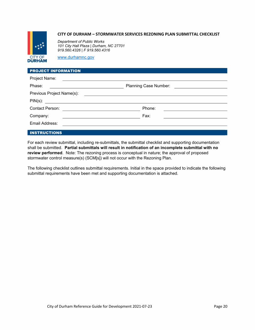
CITY OF DURHAM – STORMWATER SERVICES REZONING PLAN SUBMITTAL CHECKLIST
Department of Public Works 101 City Hall Plaza | Durham, NC 27701 919.560.4326 | F 919.560.4316
www.durhamnc.gov
PROJECT INFORMATION
Project Name:
Phase: Planning Case Number:
Previous Project Name(s):
PIN(s):
Contact Person: Phone:
Company: Fax:
Email Address:
INSTRUCTIONS For each review submittal, including re-submittals, the submittal checklist and supporting documentation shall be submitted. Partial submittals will result in notification of an incomplete submittal with no review performed. Note: The rezoning process is conceptual in nature; the approval of proposed stormwater control measure(s) (SCM[s]) will not occur with the Rezoning Plan.
The following checklist outlines submittal requirements. Initial in the space provided to indicate the following submittal requirements have been met and supporting documentation is attached.

City of Durham Reference Guide for Development 2021‐07‐23 Page 21
REZONING PLAN CHECKLIST
Initial
_____ (Check One) __ INSIDE __ OUTSIDE Watershed Protection Overlay (WPO).
Indicate the WPO(s) where the project is located:
(Check all that apply) __ F/J-A __ F/J-B __ E-A __ E-B __ M/LR-A __ M/LR-B
_____ (Check all that apply) __ Jordan Basin __ Falls Basin __ Lower Neuse Basin
_____ A legible copy of the United States Geological Survey 7.5 Minute Quadrangle map is provided, including map reference, with site boundary clearly shown and labeled. The map clearly shows all streams.
_____ A legible copy of the published Durham County Soil Survey is provided, including map reference, with the site boundary clearly shown and labeled. The map clearly shows all streams, soil types, and soil type boundaries.
_____ Tops of banks for the streams are shown on the plan. [Contact the North Carolina Department of Environment and Natural Resources for stream identifications in the Neuse River Basin (Falls and Lower Neuse Basins). Stream determinations in the Jordan Basin shall be submitted per the Letter to Industry found on Stormwater Development Review’s web site at LTI (25August2011) - New Stream Buffer Requirements.
_____ All Watershed Protection Overlay, Neuse River Basin, and Jordan Basin riparian buffers, measured from the tops of the stream banks, are shown on the plan.
_____ The 10-foot no build setback, measured from all riparian buffers, is shown on the plan.
_____ Diffuse flow is achieved into riparian stream buffers.
_____ (Check One) __ Yes __ No Regulated floodplain located on site.
_____ A legible copy of the effective Federal Emergency Management Agency (FEMA) National Flood Insurance Program Flood Insurance Rate Map is provided. Map number, map date, and site boundary are clearly shown and labeled. [This map is required regardless of whether floodplain is located on the site]. The effective and/or future FEMA 100-year floodplain, with base flood elevations, if applicable, is shown on the plan.

City of Durham Reference Guide for Development 2021‐07‐23 Page 22
CITY OF DURHAM – STORMWATER SERVICES SITE PLAN SUBMITTAL CHECKLIST
Department of Public Works 101 City Hall Plaza | Durham, NC 27701 919.560.4326 | F 919.560.4316
www.durhamnc.gov
PROJECT INFORMATION
Project Name:
Phase: Planning Case Number:
Previous Project Name(s):
PIN(s):
Contact Person: Phone:
Company: Fax:
Email Address:
INSTRUCTIONS For each review submittal, including re-submittals, the entire Stormwater Impact Analysis (SIA) and submittal checklist shall be submitted. Partial SIA and checklist will result in notification of an incomplete submittal with no review performed.
Contact Stormwater Services regarding redevelopment or expansion projects for modified requirements.
The following checklist outlines submittal requirements. Initial in the space provided to indicate the following submittal requirements have been met and supporting documentation is attached.
A. GENERAL REQUIREMENTS
Initials
_____ (Check One) __ INSIDE __ OUTSIDE Watershed Protection Overlay (WPO).
Indicate the WPO(s) where the project is located:
(Check all that apply) __ F/J-A __ F/J-B __ E-A __ E-B __ M/LR-A __ M/LR-B
If inside WPO, notation of WPO Standards is required on plans.
_____ (Check all that apply) __ Jordan Basin __ Falls Basin __ Lower Neuse Basin
_____ A legible copy of the United States Geological Survey 7.5 Minute Quadrangle map is provided, including map reference, with site boundary clearly shown and labeled. The map clearly shows all streams.
_____ A legible copy of the published Durham County Soil Survey is provided, including map reference, with the site boundary clearly shown and labeled. The map clearly shows all streams, soil types and soil type boundaries.
_____ Tops of banks for the streams are shown on the plan. [Contact the North Carolina Department of Environment and Natural Resources for stream identifications in the Neuse River Basin (Falls and Lower Neuse Basins). Stream determinations in the Jordan Basin shall be submitted per the Letter to Industry found on Stormwater Development Reviews’ web site at LTI (25August2011) - New Stream Buffer Requirements.]
City of Durham Reference Guide for Development 2021‐07‐23 Page 23
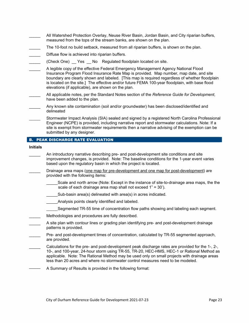
_____ All Watershed Protection Overlay, Neuse River Basin, Jordan Basin, and City riparian buffers, measured from the tops of the stream banks, are shown on the plan.
_____ The 10-foot no build setback, measured from all riparian buffers, is shown on the plan.
_____ Diffuse flow is achieved into riparian buffers.
_____ (Check One) __ Yes __ No Regulated floodplain located on site.
_____ A legible copy of the effective Federal Emergency Management Agency National Flood Insurance Program Flood Insurance Rate Map is provided. Map number, map date, and site boundary are clearly shown and labeled. [This map is required regardless of whether floodplain is located on the site.] The effective and/or future FEMA 100-year floodplain, with base flood elevations (if applicable), are shown on the plan.
_____ All applicable notes, per the Standard Notes section of the Reference Guide for Development, have been added to the plan.
_____ Any known site contamination (soil and/or groundwater) has been disclosed/identified and delineated
_____ Stormwater Impact Analysis (SIA) sealed and signed by a registered North Carolina Professional Engineer (NCPE) is provided, including narrative report and stormwater calculations. Note: If a site is exempt from stormwater requirements then a narrative advising of the exemption can be submitted by any designer.
B. PEAK DISCHARGE RATE EVALUATION
Initials
_____ An introductory narrative describing pre- and post-development site conditions and site improvement changes, is provided. Note: The baseline conditions for the 1-year event varies based upon the regulatory basin in which the project is located.
_____ Drainage area maps (one map for pre-development and one map for post-development) are provided with the following items:
_____Scale and north arrow (Note: Except in the instance of site-to-drainage area maps, the the scale of each drainage area map shall not exceed 1” = 30’).
_____Sub-basin area(s) delineated with area(s) in acres indicated.
_____Analysis points clearly identified and labeled.
_____Segmented TR-55 time of concentration flow paths showing and labeling each segment.
_____ Methodologies and procedures are fully described.
_____ A site plan with contour lines or grading plan identifying pre- and post-development drainage patterns is provided.
_____ Pre- and post-development times of concentration, calculated by TR-55 segmented approach, are provided.
_____ Calculations for the pre- and post-development peak discharge rates are provided for the 1-, 2-, 10-, and 100-year, 24-hour storm using TR-55, TR-20, HEC-HMS, HEC-1 or Rational Method as applicable. Note: The Rational Method may be used only on small projects with drainage areas less than 20 acres and where no stormwater control measures need to be modeled.
_____ A Summary of Results is provided in the following format:

City of Durham Reference Guide for Development 2021‐07‐23 Page 24
Site Analysis Point # __________
Site Condition Storm Event (cfs)
1-year (cfs) 2-year (cfs) 10-year (cfs) 100-year (cfs) ____-year (cfs)
Pre-Development
Post-Development
without Detention
Post-Development
with Detention
_____ Conclusions providing detailed findings are provided.
_____ Stormwater control measure(s) (SCM[s]) are provided (indicate number of each type of SCM):
____Level Spreader w/ Vegetative Filter Strip ____Stormwater Wetland
____Wet Detention Basin ____Sand Filter ____Bioretention ____Grassed Swale
____Restored Riparian Buffer ____Dry Extended Detention Basin
____Permeable Pavement ____Green Roof ____Disconnected Impervious Surface
____Rainwater Harvesting System
____Proprietary Systems or Other________________________________________________
____Not required (provide explanation): ____________________________________________
_____ The SCM(s) indicated above are required to control the following peak discharge rates:
____1-year ____2-year ____10-year ____100-year ____Other_________________________
_____ A downstream analysis in accordance with the Reference Guide for Development is provided with findings, or is ______Not required (provide explanation):
C. POLLUTANT CONTROL REQUIREMENTS Initials
_____ The project is exempt based upon cumulative land disturbance as of the applicable baseline date.
_____ The proposed project is ≥ 24% impervious, 85% Total Suspended Solids (TSS) removal is provided for this project, and all the impervious area as reasonably practical is treated by an SCM.
OR

City of Durham Reference Guide for Development 2021‐07‐23 Page 25
The proposed project is <24% impervious, 85% Total Suspended Solids (TSS) removal for all runoff from non-vegetated conveyances is provided for this project, and all the impervious area as reasonably practical is treated by an SCM.
OR
The project is low density (<24% impervious) without non-vegetated conveyances, thus TSS removal is not required.
_____ SCMs for TSS removal are provided (indicate number of each type of SCM): Note: Not all of the SCMs listed below provide 85% TSS removal as a stand-alone SCM and must be used in series with other SCMs to achieve the minimum TSS removal of 85%.
____Level Spreader w/ Vegetative Filter Strip ____Stormwater Wetland
____Wet Detention Basin ____Sand Filter ____Bioretention ____Grassed Swale
____Restored Riparian Buffer ____Dry Extended Detention Basin
____Permeable Pavement ____Green Roof ____Disconnected Impervious Surface
____Rainwater Harvesting System
____Proprietary Systems or Other________________________________________________
____Not required (provide explanation):
_____ Excel-format electronic copies of the following:
Pre- and post-development nutrient calculations using the Jordan/Falls Lake Stormwater Nutrient Load Accounting Tool (for Lower Neuse Basin) or North Carolina Stormwater Nitrogen and Phosphorus Tool (for Falls Basin).
Note: Nutrient calculations are always required unless the project is exempt from treatment requirements.
The Nutrient Reporting Form (including the Compliance Worksheet tab) per the 3/7/2013 Letter to Industry http://durhamnc.gov/documentcenter/view/3185.
_____ Pre- and post-development land use area maps that correspond to the categories used in the Jordan/Falls Lake Stormwater Nutrient Load Accounting Tool (for Lower Neuse Basin) or the North Carolina Stormwater Nitrogen and Phosphorus Tool (for Falls Basin) for the nutrient calculations, to scale no smaller than 1 inch = 100 feet. The maps shall show the map scale, north arrow, and are to have the different land uses either hatched or shaded with areas indicated in a legend on the maps. Note: The land use area maps are always required unless the project is exempt from treatment requirements.

City of Durham Reference Guide for Development 2021‐07‐23 Page 26
_____ SCMs for nutrient control are provided (indicate number of each type of SCM):
____Level Spreader w/ Vegetative Filter Strip ____Stormwater Wetland
____Wet Detention Basin ____Sand Filter ____Bioretention ____Grassed Swale
____Restored Riparian Buffer ____Dry Extended Detention Basin
____Permeable Pavement ____Green Roof ____Disconnected Impervious Surface
____Rainwater Harvesting System
____Proprietary Systems or Other________________________________________________
____Not required (provide explanation):
_____ After meeting the minimum on-site treatment requirements, additional treatment and/or offsite credit purchases, if needed, is provided by:
____Additional SCMs
____Nutrient Offset Payment to the North Carolina Ecosystem Enhancement Program
____Nutrient Offset Payment to an Approved Nutrient Bank
_____ The project site is located in an area subject to a state-approved Total Maximum Daily Load (TMDL) for bacteria. (As of December 2019, only Northeast Creek has a TMDL for bacteria and Third Fork Creek has a TMDL for turbidity).
_____ SCMs rated as medium or high for bacterial removal are provided (indicate number of each type of SCM):
____Bioretention Area ____ Stormwater Wetlands
____Wet Detention Basin ____ Sand Filter
____Level Spreader w/ Vegetative Filter Strip ____Restored Riparian Buffer
____Dry Extended Detention Basin ____ Permeable Pavement
____Other (specify)_____________________________________________________________
____Not required (provide explanation):
D. WATERSHED PROTECTION OVERLAY REQUIREMENTS

City of Durham Reference Guide for Development 2021‐07‐23 Page 27
Initials
_____ 85% Total Suspended Solids (TSS) removal is required for this project, and 100% of the impervious area will be treated by an SCM. Note: Not all of the SCMs listed below provide 85% TSS removal as a stand-alone SCM and must be used in series with other SCMs to achieve the minimum TSS removal of 85%.
_____ SCM for TSS removal are provided (indicate number of each type of SCM):
____Level Spreader w/ Vegetative Filter Strip ____Stormwater Wetland
____Wet Detention Basin ____Sand Filter ____Bioretention ____Grassed Swale
____Restored Riparian Buffer ____Dry Extended Detention Basin
____Permeable Pavement ____Green Roof
____Disconnected Impervious Surface ____Rainwater Harvesting System
____Proprietary Systems or Other________________________________________________
____Not required (provide explanation):
E. ELECTRONIC FILE SUBMITTAL
Initials
_____ Electronic submittal requirements including the following submittals in accordance with Development Service Center protocols:
____Sealed SIA: entire document including narrative, data, calculations, pre- and post-development drainage area maps, pre- and post-development land use area maps that correspond to the categories used in the JFLSAT/SNAP Tool, and all appendices (pdf format)
____Jordan/Falls Lake Stormwater Accounting Tool or North Carolina Stormwater Nitrogen and Phosphorus Tool (Excel format)
____Nutrient Reporting Form (Excel format)

City of Durham Reference Guide for Development 2021‐07‐23 Page 28
CITY OF DURHAM – STORMWATER SERVICES FINAL PLAT SUBMITTAL CHECKLIST
Department of Public Works 101 City Hall Plaza | Durham, NC 27701 919.560.4326 | F 919.560.4316
www.durhamnc.gov
PROJECT INFORMATION
Project Name:
Phase: Planning Case Number:
Previous Project Name(s):
PIN(s):
Contact Person: Phone:
Company: Fax:
Email Address:
INSTRUCTIONS For each review submittal, including re-submittals, the submittal checklist shall be submitted with the final plat. Partial submittals will result in notification of an incomplete submittal with no review performed. The following is a list of standard final plat requirements that are reviewed by Stormwater Services. This list is intended to give general guidelines only and is not to be considered all-inclusive. Depending upon the development, additional items may be required.
Initial in the space provided to indicate the following submittal requirements have been met and supporting documentation is attached.

City of Durham Reference Guide for Development 2021‐07‐23 Page 29
FINAL PLAT CHECKLIST
Initials
_____ All stormwater control measure(s) (SCM[s]) are delineated and labeled as shown on the approved construction drawings or as constructed. A note may be added to reference the source of the SCM delineation when not constructed and taken from approved construction drawings.
_____ All SCM access and maintenance easements are shown on the final plat exactly as prescribed on the approved construction drawings.
_____ The easement note per the Standard Notes section of the Reference Guide for Development has been added to the final plat for the SCM access and maintenance easement(s).
_____ The restrictive covenants note per the Standard Notes section of the Reference Guide for Development has been added to the final plat for developments with SCMs to ensure responsibilities of HOA members are clearly acknowledged.
_____ The effective and/or future Federal Emergency Management Agency (FEMA) 100-year floodplain, with base flood elevations (if applicable), is shown on the final plat. The effective FEMA National Flood Insurance Program Flood Insurance Rate map number, map date, and flood zones are indicated on the final plat. [Note that the map number, map date, and flood zones shall be indicated on the final plat even if floodplain is not present on the property.]
_____ The maximum impervious surface area per lot when located in a Watershed Protection Overlay, as was approved on the site plan and in the stormwater impact analysis.
_____ Tops of banks for the streams are shown on the final plat. [Contact the North Carolina Department of Environment and Natural Resources for stream identifications in the Neuse River Basin (Falls and Lower Neuse Basin). Stream determinations in the Jordan Basin shall be submitted per the Letter to Industry found on Stormwater Development Review’s web site at LTI (25August2011) - New Stream Buffer Requirements.
_____ All Watershed Protection Overlay, Neuse River Basin, Jordan Basin, and City riparian buffers, measured from the tops of the stream banks, are shown on the final plat.
_____ The 10-foot no build setback, measured from all riparian buffers, is shown on the final plat.
_____ The riparian buffer standard note per the Durham City-County Planning Department has been added to the final plat.
_____ For residential subdivisions: the SCM(s) serving any part of the platted property has been as-built, certified, and completion certificate(s) issued or an SCM construction security for 125% of the approved engineer’s construction completion cost estimate has been provided.
Note: In accordance with the Planning Unified Development Ordinance, Stormwater Services reviews final plats for a specific site after the construction drawings for that site have been approved by the City. As such, Stormwater Services does not review final plats that are only for right-of-way dedication and will have no comments on these types of final plats.
City of Durham Reference Guide for Development 2021‐07‐23 Page 30
1.3 Department of Transportation’s Role and Submittal Requirements
A. Contact Information
The Department of Transportation’s Development Review Group is located on the 4th floor of City Hall and can be reached at (919) 560-4366 and fax number (919) 560-4561. Correspondence can be sent to:
Department of Transportation 101 City Hall Plaza Durham, NC 27701
B. Transportation Development Review Group’s Role
1. Rezonings, Site Plans, and Preliminary Plats
The Department of Transportation is tasked with reviewing rezoning, site plans and preliminary plats as these items relate to:
Proposed public rights-of-way Cross-sections on proposed/existing roads Preserving the most current Durham area Transportation(s) Plan (possible right-of way dedication
and/or upgrade of the existing infrastructure) Preserving the Bicycle Plan Placement of sidewalk Sight distance triangles Vehicular and pedestrian accesses Site traffic analyses (if necessary) Interconnectivity of developments and points of access
2. Final Plats
The Department of Transportation is tasked with reviewing final plats as they relate to:
Proper public rights-of-way or private accesses (easements) Conforming to street naming convention for signage
C. Submittal Requirements
The Department of Transportation submittal checklists contain the minimum requirements for Planning submittals. These checklists shall be used as a guide prior to submitting any Site Plan, Preliminary Plat, or Final Plat. The Site Plan and Preliminary Plat Submittal Checklist and the Final Plat Submittal Checklist are not required to be submitted with the plans. The checklists are located online and below.

City of Durham Reference Guide for Development 2021‐07‐23 Page 31
CITY OF DURHAM – TRANSPORTATION SITE PLAN AND PRELIMINARY PLAT CHECKLIST
Department of Transportation 101 City Hall Plaza | Durham, NC 27701 919.560.4366 | F 919.560.4561
www.durhamnc.gov
The following is a list of site plan and preliminary plat requirements from the Department of Transportation. This list is intended to give general guidelines only and is not to be considered all-inclusive.
1. Access Points
a) 90 or less units – one public street access b) More than 90 units – 2 public street accesses c) Add a note on the plan regarding the limit of units before another access street is built d) Access points needed for connectivity
2. Usability of Access Point
a) Sight distances (horizontal and vertical alignments and obstructions) b) Landscaping in right-of-way or interfering with sight distance (sight triangle) c) Sight distance triangles for adjacent drives d) Relationship to other streets and drives e) Entrance type f) Turning radii (particularly fire access) g) Turning lanes (left and right turns in and out)
3. Adjoining Property
a) Dedicated streets (are connections made or needed?) b) Land locking (is access to adjoining property needed?)
4. Conformance with adopted plans
a) Impact of any proposed transportation improvements adjacent to or through the property (right-of-way and construction)
b) Additional right-of-way needed on streets adjoining project
5. Street Design
a) Meets Table of Minimum Design Requirements for Public and Private Residential Streets b) Sight Distance (vertical and horizontal curves, landscaping, signs etc.) c) Street Lighting d) Driveway spacing, width, location and distance from intersection e) Correct street and right-of-way width – according to street type f) Provisions for on-street parking g) Minimum centerline radius – as per design speed h) Maximum cul-de-sac length = 800’ i) Minimum cul-de-sac bulb radius j) Corner right-of-way radius or sight triangle needed k) Accommodations for bicyclists (Durham Comprehensive Bicycle Transportation Plan) l) Adequate right-of-way width to accommodate sidewalk and other proposed improvements. Is there a
dedication of right-of-way?

City of Durham Reference Guide for Development 2021‐07‐23 Page 32
6. Parking
a) Parking location and control (maneuvering away from entrances and intersections) b) Parking stalls and aisle widths c) Handicapped parking requirement and van accessibility d) Bicycle parking (number, location, rack type) e) Is a complex source permit required?
7. Miscellaneous
a) Dumpster location and access b) Pedestrian access (internal and external sidewalks) c) Stacking requirements d) Internal site circulation e) Transit accommodations (where applicable) f) Off-site improvements needed (signals, street widening, turn lanes at intersections, etc.) g) Traffic Impact Analysis required (peak hour generation > 150 trips) h) Name and dimension cross-sections and right-of-way i) General notes
City of Durham Reference Guide for Development 2021‐07‐23 Page 33
CITY OF DURHAM – TRANSPORTATION FINAL PLAT CHECKLIST
Department of Transportation 101 City Hall Plaza | Durham, NC 27701 919.560.4366 | F 919.560.4561
www.durhamnc.gov
The following is a list of final plat requirements from the Department of Transportation. This list is intended to give general guidelines only and is not to be considered all-inclusive.
1. Show required right-of-way and right-of-way dedication (from site plan) 2. Make sure that the plat does not create any land locked parcels 3. Make sure that the street names on the plat agree with the street naming convention of the City and
County of Durham 4. Illustrate required sight triangles

City of Durham Reference Guide for Development 2021‐07‐23 Page 34
Section 2: City of Durham Construction Drawing
Review and Construction Process
2.1 Review Group’s Role in the Construction Drawing Review Process
The following information is to provide a basic overview of the roles of the above divisions as they relate to the construction drawing review process. All materials shall be submitted to the Development Services Center (https://dsc.durhamnc.gov/234/2482/Construction-Drawings-submittal-portal?activeLiveTab=widgets). Status inquires and correspondences associated with review comments can be directed to the individual reviewer of each Division.
A. Engineering Division
The City of Durham Engineering Development Review is tasked with reviewing construction documents as these items relate to the City of Durham public and private road standards, driveways, sidewalks, water systems, fire protection systems, sanitary sewer systems, stormwater drainage and conveyance systems and easements for these systems.
The Engineering Development Review Group is located on the 3rd floor of City Hall and can be contacted by mail at the following address: Public Works Department Engineering Division 101 City Hall Plaza Suite 3100 Durham, NC 27701. The Engineering Development Review Group can be reached at (919) 560-4326 and fax number (919) 560-4316.
B. Stormwater Services Division
The City of Durham Stormwater Services Development Review Group is tasked with reviewing construction drawing documents as these items relate to stormwater impact analyses/studies, compliance with approved site plans/preliminary plats, design of stormwater quality and/or quantity facilities, coordination of stream buffers and special flood hazards with Planning/Development Services, etc.
The Stormwater Services Development Review Group is located on the 3rd floor of City Hall and can be contacted by mail at the following address: Public Works Department Stormwater Services Division 101 City Hall Plaza Suite 3100 Durham, NC 27701. The Stormwater Services Development Review Group can be reached at (919) 560-4326 and fax number (919) 560-4316.
C. Department of Transportation
The City of Durham Department of Transportation Development Review Group is tasked with reviewing construction documents as they pertain to traffic control devices, signs, pavement markings, lane widths, design and traffic control of roundabouts and placement and design of traffic calming measures. The Transportation Division can be contacted by mail at the following address: Department of Transportation, City of Durham, 101 City Hall Plaza, 4th Floor, Transportation Division, Durham, North Carolina, 27701. The contact phone number for questions is (919) 560-4366 and fax number is (919) 560-4561.

City of Durham Reference Guide for Development 2021‐07‐23 Page 35
D. Department of Water Management
The City of Durham Department of Water Management is tasked with reviewing construction documents for lift stations. The Utility Engineering Division can be contacted by mail at the following address: 1600 Mist Lake Drive, Durham, North Carolina, 27704. The contact phone number for questions is 919-560-4381.
Submit the Intent to Construct a Lift Station Package and Calculation Review Package prior to submitting construction drawings for lift stations (as required in the City of Durham Lift Station Design Standards).
E. City‐County Development Services Center
The City-County Development Services Center (https://dsc.durhamnc.gov/) is tasked with reviewing construction documents as they pertain to floodplain and stream buffer intrusions. Development Services Center can be contacted by mail at the following address: 101 City Hall Plaza Ground Floor Durham, NC 27701. The contact phone number for questions is 919-560-4137 and fax number 919-560-4144.
2.2 When Are Construction Drawings Required?
This section is intended to notify the Engineer and the Developer of those plans that need to be submitted for review and approval before construction can begin. Note: Construction plan approval process typically begins after Zoning and Site Plan approval (may run concurrently with site plan review).
Construction drawings can’t be approved without a valid/approved site plan. If there is any question about the validity of the plan contact the City/County Planning Department.
Table 2.1: Improvements Requiring Construction Drawings
Type of Development Construction Plan Required
Refer to Section
Commercial/Institutional/Educational Yes if any items are listed as 'Yes' in Specific Improvements below
2-9
Multifamily Yes 2-9 Subdivision Yes 2-9 Specific Improvements Construction Plan Required Refer to Section Water system Service (lateral) No 3 (Building Inspections) Water main extension Yes 5 Fire line Yes 5 Backflow prevention (BFP outside building) Yes 6 Hydrant Yes 5 Sanitary sewer system 4” service serving 1 building (lateral) No 3 (Building Inspections) 4” service serving 2 or more buildings Yes 7 6” service that serving 1 building (lateral) No 3 (Building Inspections) Main extensions (pipes 6” or greater) Yes 7 Outfalls Yes 7 Pump stations/forcemains Yes 7 Industrial Yes Water Management Storm Drainage Pipes or conveyance of 15” diameter or Yes 8

City of Durham Reference Guide for Development 2021‐07‐23 Page 36
larger Stormwater Control Measure Yes 8-8.6 Streets (public or private) New streets or private access Yes 9 Turn lanes or road widenings Yes 9 Driveways Commercial with approved site plan No, right of way permit required 3 Commercial when site plan not required Yes, right of way permit required 3 Single-family and townhome with approved site plan
No, right of way permit required 3
Single-family and townhome when site Plan not required
Yes, right of way permit required 3
Sidewalk and curb ramps with approved site plan No, right of way permit required 11 when site plan not required Yes 11
2.3 Construction Drawing Approval Process
This section is intended to aid in the process of construction drawings submittal.
A. Before Submitting Construction Drawings
If a site plan is required, obtain site plan approval prior to the construction drawing review or submit construction drawings concurrently with the site plan review (preferably after one review of the site plan has been completed). Construction drawings can’t be approved until the site plan is approved. Be aware that some site plans may have expiration dates. If there are any questions, contact the City/County Planning Department at (919) 560-4137.
Some projects require additional approvals that are beyond local authority (for example: erosion control permits, wetland permits, etc.). The City of Durham Engineering Division requires that all appropriate agencies be contacted and approvals for the plans shall be obtained. Even if the Engineering Division does not ask for proof of approvals, it does not relieve the applicant from obtaining them.
If water and/or sanitary sewer lines (mains and/or services) are extended outside the City Limits, an Extension Agreement Application and Annexation Petition Package shall be submitted to the City/County Planning Department (this is typically done at rezoning or prior to site plan review). The Extension Agreement shall be approved by the City Council prior to approval of the Construction Drawings. If the site is located within the City Limits the Engineering Division may require an Extension Agreement Application to be submitted. The request for the Extension Agreement Application is typically done during rezoning or site plan review, but if these are not required for the project, the Extension Agreement Application may be requested during construction drawing review.
Developers shall engage the services of a Professional Engineer registered in the State of North Carolina (NCPE) to prepare, sign and seal plans and specifications for the construction of all streets, water, sanitary sewer and applicable storm drainage systems and structures (Developers may also engage the services of a registered Professional Land Surveyor or Landscape Architect registered in the State of North Carolina to prepare, sign, seal plans and specifications for the construction of streets and applicable storm drainage systems and structures). For more detailed requirements of these construction plans see also the Sections 2.3, Construction Phase, through Section 11.0, Standard Notes.
Sanitary sewer pump stations for projects will require coordination with the Department of Water Management prior to submittal of site plan and/or construction drawings. This is to determine if the station is feasible and to determine the design parameters that apply.

City of Durham Reference Guide for Development 2021‐07‐23 Page 37
B. Construction Drawing Submittal Requirements
The consultant shall prepare constructions drawings in accordance with the approved site plan and the City of Durham Reference Guide for Development. The construction drawings shall be submitted to the Development Services Center through their online submittal portal (https://dsc.durhamnc.gov/234/2482/Construction-Drawings-submittal-portal?activeLiveTab=widgets).
The consultant shall complete the City of Durham Construction Drawing Submittal Checklist. The consultant shall mark on the checklist all the appropriate Review Groups that are required to review the construction drawings (see Section 2.1 above).
Engineering Division Stormwater Services Division Department of Transportation Department of Water Management City-County Development Services Center
Not all construction drawings need to be reviewed by all the Review Groups. The consultant shall include all required items listed on the checklist for the relevant Review Groups with the construction drawings.
All submittals will be reviewed for completeness (triage process) by the end of the second business day after receipt. The submittal is considered incomplete if any of the required items from the submittal checklist are missing. The review process will not start until all required items are received. Email [email protected] if you have questions about the triage process.
C. Construction Plan Approval Process
All complete construction drawing submittals will be assigned to the appropriate Review Groups for review. The typical time line for review of construction drawings is approximately 10 business days from the day the construction drawings have successfully been triaged.
When the reviews are completed the contact person listed in the submittal checklist will be notified that redlined plans and reports are available for download in the online portal.
Revise the construction drawings and reports per the Review Groups comments. Provide responses to construction drawing comments directly on the redlined plans or in letter format. Complete a new City of Durham Construction Drawing Submittal Checklist and resubmit the construction drawings and all required items through the online portal. The submittal will be triaged again. A typical construction drawing submittal may have 3 to 4 review cycles.
When plans have completed the last review cycle and there are no further comments from any of the Review Groups, the consultant will be instructed to provide all stormwater fees, surety and maintenance agreements if applicable (see note below) and to submit original drawings (reproducibles) for signatures and approval (see sample of stamp at the end of this section).
Note: Permit fee, surety and executed maintenance agreements for stormwater quality and/or quantity best management practices are required per the Stormwater Services Division. No plans will be allowed to proceed with construction until all of these items are completed.
Figure 2.1: Approval Stamp to be Provided on all of the Construction Drawing Sheets
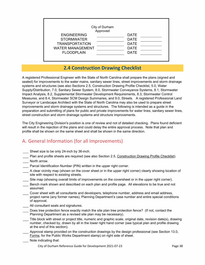
City of Durham Reference Guide for Development 2021‐07‐23 Page 38
City of Durham Approved
ENGINEERING DATE STORMWATER DATE
TRANSPORTATION DATE WATER MANAGEMENT DATE
FLOODPLAIN DATE
2.4 Construction Drawing Checklist
A registered Professional Engineer with the State of North Carolina shall prepare the plans (signed and sealed) for improvements to the water mains, sanitary sewer lines, street improvements and storm drainage systems and structures (see also Sections 2.5, Construction Drawing Profile Checklist, 5.0, Water Supply/Distribution, 7.0, Sanitary Sewer System, 8.0, Stormwater Conveyance Systems, 8.1, Stormwater Impact Analysis, 8.2, Supplemental Stormwater Development Requirements, 8.3, Stormwater Control Measures, and 8.4, Stormwater SCM Design Summaries, and 9.0, Streets. A registered Professional Land Surveyor or Landscape Architect with the State of North Carolina may also be used to prepare street improvements and storm drainage systems and structures. The following is intended as a guide in the preparation and submitting of plans for public and private improvements for water lines, sanitary sewer lines, street construction and storm drainage systems and structure improvements.
The City Engineering Division's position is one of review and not of detailed checking. Plans found deficient will result in the rejection of the plans and could delay the entire approval process. Note that plan and profile shall be shown on the same sheet and shall be shown in the same direction.
A. General Information (for all Improvements)
___ Sheet size to be only 24-inch by 36-inch.
___ Plan and profile sheets are required (see also Section 2.5, Construction Drawing Profile Checklist).
___ North arrow.
___ Parcel Identification Number (PIN) written in the upper right corner.
___ A clear vicinity map (shown on the cover sheet or in the upper right corner) clearly showing location of site with respect to existing streets.
___ Site map (showing overall limits of improvements on the coversheet or in the upper right corner).
___ Bench mark shown and described on each plan and profile page. All elevations to be true and not assumed.
___ Cover sheet with all consultants and developers, telephone number, address and email address, project name (any former names), Planning Department’s case number and entire special conditions of approval.
___ All consultant seals and signatures.
___ Does tree protection fence exactly match the site plan tree protection fence? (If not, contact the Planning Department as a revised site plan may be necessary).
___ Title block with street or project title, numeric and graphic scale, original date, revision date(s), drawing number, checked by, drawn by all in the lower right hand corner (see typical plan and profile drawing at the end of this section).
___ Approval stamp provided on the construction drawings by the design professional (see Section 13.0, Forms, for the Public Works Department stamp) on right side of sheet.
___ Note indicating that:

City of Durham Reference Guide for Development 2021‐07‐23 Page 39
City of Durham standards and specifications are to be used.
___ Clearing limits shown.
Note: If the clearing limits are different than what was approved on the site plan, the revised site plan shall be signed off by the Planning Department prior to approval of the construction drawings. This could require that the plan go through the entire Planning Department development review cycle.
___ Adjacent owner(s) showing:
___ Names (optional).
___ Property lines.
___ Addresses (optional).
___ Tax map numbers.
___ Parcel Identification numbers.
___ Right-of-Way widths.
___ Existing and proposed with dimensions.
___ Easements, existing and proposed with dimensions.
___ Reference of plat book and page for dedication of additional right-of-way (if available).
___ Existing iron pins from location survey (optional).
___ If on a NCDOT road:
___ Reference state road number and street name.
___ Reference centerline intersection distance to nearest state road cross street.
___ Beginning and ending stations, including matchline stations for multiple sheets.
___ Easement Notes (see also section on Section 11.0, Standard Notes).
___ Legend for drawing symbols.
___ Drawing symbols to be proportionate.
___ Existing paved roads are to be bored for water and sanitary sewer crossings. Show /label and dimension encasement pipe, carrier pipe, and bore pit (at least 30 feet long).
___ Show all guardrails (include detail). Use standard NCDOT guardrail.
___ Provide standard utility crossing note on the overall utility plan (See Section 11.0, Standard Notes).
___ Phasing of the project shall match phasing shown in approved site plan. Provide water valve, manhole, and temporary turn-around at all phase lines.
B. Water Mains
___ Existing/proposed water lines shown (sizes, material, and if public or private) and labeled.
___ Dimension and show proposed water main from centerline or right-of-way.
___ Proposed water services installed at right angle to street.
___ Label size of all proposed tees, bends, and blow-off assemblies.
C. Sanitary Sewer Mains
___ Existing/proposed sanitary sewer lines shown (sizes, material, and if public, County, or private) and labeled.
___ Show angle alignment on outfalls.
___ Dimension proposed manhole from centerline.
___ Station manholes from left to right.
___ For outfalls orient the layout so that the lowest elevation manhole is on the left.

City of Durham Reference Guide for Development 2021‐07‐23 Page 40
___ Manholes: station and label.
___ Existing manholes with proposed sanitary sewer connections show the following note: Core drill and install flexible rubber boot.
___ Label the manholes as a drop connection or doghouse as appropriate.
___ Show manhole rims 2-feet above 100-year floodplain elevation (existing or created).
___ All manholes not in street right-of-way to be 3-feet above finished grade.
___ Show stub-out or knock out for future sewer. Stub outs require a minimum sanitary sewer line length of 5-feet (and cap) from the manhole for future sanitary sewer or as directed by the City Engineering Division.
___ Lateral cleanouts shall be located at the easement or right-of-way line.
___ 4-inch lines should tie into the sanitary sewer main with a tap (avoid the manhole) except at cul-de-sacs or as approved by the City Engineering Division.
___ 6-inch lines and larger must tie into a manhole.
___ Show sanitary sewer services installed at right angles to the street/sanitary sewer easement for all lots and buildings.
___ Dumpster pads for food service establishments and all establishments utilizing a compactor shall have a drain connected to the sanitary sewer with a grease trap. Only the runoff from the dumpster pad shall be directed to the dumpster drain.
___ No storm structures or conveyance systems are shown in sanitary sewer easements except as crossing at 90 degrees.
___ Minimum sanitary sewer easement width for sanitary sewer mains is 30-feet and 5-feet building setback. No combined easements are allowed. Overlapping easements are allowed, so long as any structures or conveyance systems are located outside of the sanitary sewer easement and all easements are labeled separately.
Anti-floatation calculations for manholes where high groundwater conditions are anticipated.
D. Storm Drainage
___ An overall grading and drainage plan provided showing existing and proposed grading.
___ Storm drainage calculations with hydraulic grade lines, gutter spread, culvert, flume, overland-relief, and scour velocity and supporting documentation (does not need to be on drawings). See also Section 8.0, Stormwater Design Criteria.
___ Signed and sealed by a registered Professional Engineer if system intercepts stormwater from public streets or offsite drainage.
___ Show all on-site and adjacent storm drainage facilities.
___ Existing drainage shown and labeled including pipes, culverts, manholes, catch basins, ditches, headwalls, endwalls, etc. and appropriate sizes and inverts.
___ Proposed drainage system shown and labeled (numbered) on overall grading and drainage plan.
___ Proposed storm drainage table showing sizes, inverts, grades, lengths, rims, materials, etc.
___ Outlet and inlet protection (type, size/dimensions, material, etc.).
___ Channel detail with size, typical section, lining, etc. (on the construction drawing).
___ Show and label all storm drainage easements.
___ Floodplain data (fringe line, elevation, floodway, and FEMA panel number).
___ Delineated wetlands.
___ Existing bodies of water (lakes, streams, creeks, etc.) with stream buffers and note (see Section 11.0, Standard Notes).
City of Durham Reference Guide for Development 2021‐07‐23 Page 41
___ Show erosion control sediment basin locations. Basins not to be located on or cause stormwater to be retained on sanitary sewer easement or public right-of-way.
___ For public streets with 24-inch pipe or larger include a 4-feet high PVC coated dark green chain link fence at the right-of-way. Length shall be extended to end of fill section as it intersects existing grade.
___ Flared end sections or headwalls are required at beginning and end of all stormwater pipes.
___ Headwalls and endwalls or flared end sections are required on all pipes, however Stormwater Services reserves the right to require headwalls and endwalls instead of flared end sections or vice versa.
___ Minimum stormwater easement width shall be determined per guidelines (Section 8.0, Stormwater Design Criteria). Show 2-feet setback from stormwater easement. No combined easements are allowed. Overlapping easements are allowed, as long as any structures for other utilities are located outside of the stormwater easement and all easements are labeled separately.
___ Overland relief shall be provided for all stormwater pipe systems, inlets, and culverts such that no building or habitable structure will be flooded or have water impounded against it during the 100-year storm event.
E. Streets (Refer to Section 9.0 for Acceptable Street Types)
___ Provide all street centerline bearings and distances. Provide all centerline radii and length of curves.
___ Provide a typical cross section with pavement thickness.
___ Street names and State road numbers if applicable.
Existing pavement width (show shaded) dimensioned to back of curb (BOC).
___ Curve data with super elevation, runoff data and design speed.
___ Residential streets are designed without superelevation. If superelevation is desired or needed, submit a sketch to City Engineering indicating why this is needed.
___ Existing and proposed centerlines (if different or new streets are proposed), curb and gutter, edge of pavement, driveways (with widths and material type), sidewalks, handicap ramps, etc. (All center line information shall contain bearing and distance as well as all horizontal curve information).
___ Roll curb shall transition to standard curb at all radii, catch basins, fire hydrants, and as directed by the Engineering inspector during construction.
___ Stations along centerline and at special features (point of tangent, point of curve, catch basins, centerline point of intersection, low/high point, etc.).
___ Taper and lane storage lengths shown. Calculations of lengths to be placed directly on drawings.
___ Obstructions labeled.
___ Posted speed limits for widening of existing streets.
___ Design speed of new streets.
___ Utilities identified and labeled.
___ Trees and shrubs shown and labeled to remain and those to be removed.
___ Street intersection turnouts with radii.
___ Proposed elevations and grades around cul-de-sac and street intersection radii.
___ Street width (back of curb), right-of-way width and all street intersection radii.
___ Signing and Pavement Markings Sheet (when necessary, see Section 10.0, Transportation).
___ At all road stubs to adjacent properties where required by the Public Works Department, the consultant shall provide all requested future street profiles for review and approval.
2.5 Construction Drawing Profiles Checklist
Profile drawings are required when:
City of Durham Reference Guide for Development 2021‐07‐23 Page 42
Waterline main extensions in existing or new streets Private water lines where they cross sanitary sewer lines (a cross-section is acceptable or
dimension if crossing is on the plan view) Sanitary sewer main extensions Public and private streets
A registered Professional Engineer with the State of North Carolina shall prepare the plans (signed and sealed) for improvements to the water mains, sewer mains, street improvements and storm drainage systems and structures. A registered Professional Land Surveyor or Landscape Architect with the State of North Carolina may also be used to prepare street improvements and storm drainage systems and structures (see also Sections 2.4, Construction Drawing Plan Checklist, 5.0, Water Supply/Distribution, 7.0, Sanitary Sewer System, 8.0, Stormwater Conveyance Systems, 8.1, Stormwater Impact Analysis, 8.2, Supplemental Stormwater Development Requirements, 8.3, Stormwater Control Measures, and 8.4, Stormwater SCM Design Summaries, and 9.0, Streets). The following is intended as a guide in the preparation and submitting of plans for improvements for water lines, sewer lines, street construction and storm drainage system and structures. The City Engineering Division's position is one of review and not of detailed checking. Plans found deficient will result in the rejection of the plans and could delay the entire approval process.
A. General
___ Plan view, required for all profile drawings (see Section 2.4, Construction Drawing Plan Checklist).
___ The plan view is to be at the top and the profile view is to be at the bottom of the sheet (see plan profile sheet at the end of this section for general layout and configuration). Note that plan and profile must be shown on the same sheet and must be shown in the same direction.
___ For all improvements:
___ Sheet size to be 24-inch by 36-inch.
___ The scale shall be: 1-inch = 40-feet horizontally and 1-inch = 4-feet vertically. Show the scale both numerically and graphically.
___ Bench mark shown and described on each plan and profile page. All elevations to be true and not assumed.
___ Elevations shall be labeled in 10-foot intervals on the heavy lines (Ex. 360, 370).
___ Existing centerline profile shall be extended adequately to design future extensions (300-feet preferred).
___ Existing paved roads are to be bored for water and sanitary sewer crossings. Show/label and dimension encasement pipe and carrier pipe and vertical clearance to other pipes crossed.
___ All labels shall be legible and horizontal or vertical. The bottom of all labels shall face toward the bottom of the sheet or the right side of the sheet, whichever is applicable.
B. Water Mains
___ Existing water lines shown with size and type.
___ Proposed water lines shown with size and type.
___ Show minimum cover for proposed underground utilities (3-feet minimum or as required by the Engineering Division).
___ Waterlines above sewer lines.
___ Show minimum clearance between utilities:
___ 18-inches vertical above sanitary sewer lines or 10-feet horizontal from sanitary sewer line.
___ 12-inches from storm drainage lines.

City of Durham Reference Guide for Development 2021‐07‐23 Page 43
___ Waterlines below sanitary sewer lines (sanitary lines shall be ductile iron for 10-feet on either side of crossing).
C. Sanitary Sewer Mains
___ Existing sanitary sewer lines shown with size and type.
___ Proposed sanitary sewer lines shown with size and type.
___ Show sanitary sewer grades, inverts at manholes, lengths, rims, etc.
___ Show intersecting inverts and label invert elevations.
___ Show centerline of intersecting streets with stations.
___ Check grades and inverts for accuracy.
___ Show minimum clearance between utilities:
___ 18-inches vertical below waterlines or 10-feet horizontal from waterlines.
___ 18-inches from storm drainage lines.
___ Indicate 100-year flood elevation (reference FEMA panel #, date).
___ Show manhole rims 2-feet above 100-year floodplain elevation (existing or created).
___ All manholes not in street right-of-way to be 3-feet above finished grade.
___ Add shading to all ductile iron pipe sanitary sewer lines in profiles to distinguish DIP material from PVC material.
___ DIP used as force mains to be lined with “Protecto 401” or equivalent.
D. Storm Drainage
___ Submit drainage calculations (see Section 8.0, Stormwater Design Criteria, for required drainage calculations).
___ Show existing drainage to remain with inverts, size, etc.
___ Show proposed drainage with inverts, grades, size, length, etc.
___ Maintain a minimum of 1% grade on storm drainage pipes. Further calculations will be required for grades less than 1%, but only with Stormwater Services Approval.
___ Easements required when pipe or channel collects stormwater from a public right-of-way. Easement width to be determined Section 8.0, Stormwater Design Criteria). See Section 11.0, Standard Notes, for storm easement note.
E. Street Design
___ Typical section of proposed street if not already shown on plan (refer to Section 9.0, Streets, for acceptable street types).
___ Existing and proposed centerline profile.
___ Existing top of curb profile.
___ Proposed centerline vertical curve information (VPI, VPC, VPT, Elevation, L, DS based on AASHTO and K value). Show TOC elevations at locations not covered by centerline vertical curve information.
___ Proposed grade lines with percent grade shown.
___ Maintain a minimum of 0.7% grade.
___ Existing elevations shown along centerline, right right-of-way and left right-of-way.
___ Profile shall be projected straight down from plan view whenever possible.
___ Show street intersection turnouts in the profile with elevations given at PC, 1/4, 1/2, 3/4, PT.

City of Durham Reference Guide for Development 2021‐07‐23 Page 44
___ At all road stubs to adjacent properties where required by the Public Works Department, the consultant shall provide all requested future street profiles for review and approval.
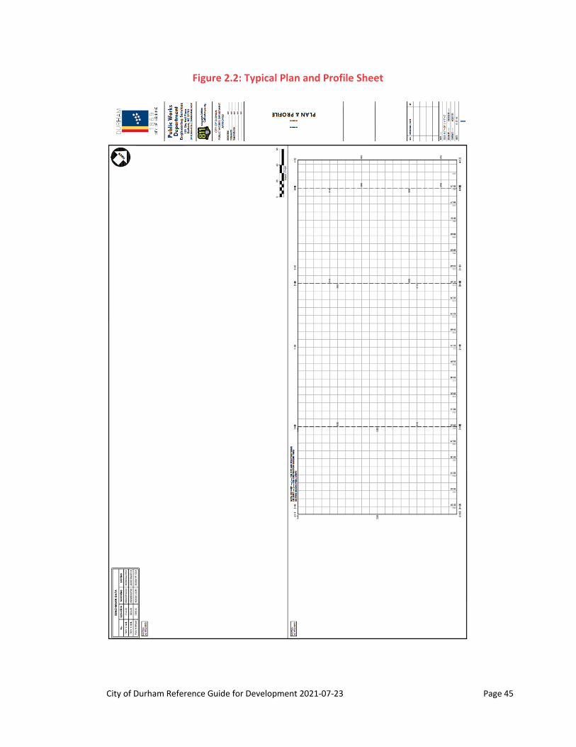
City of Durham Reference Guide for Development 2021‐07‐23 Page 45
Figure 2.2: Typical Plan and Profile Sheet

City of Durham Reference Guide for Development 2021‐07‐23 Page 46
2.6 Construction Permitting
After construction plans are approved and signed by all applicable Review Groups, the applicant will receive signed originals/reproducibles and a City of Durham Letter of Transmittal. The Letter of Transmittal will indicate required permits, the number of copies of the approved construction drawings to be submitted to Engineering Services, and permit fees.
All projects with approved construction drawings are required to submit the following to Engineering Services at the 3rd floor of City Hall or online before the start of construction:
1. Project Information sheet with 4 copies (entire sets) of approved construction drawings
2. Email or load to Box.com with the project name and planning case number the following files:
Combined (one single PDF) file of scans (200 dpi, grayscale) of all sheets of the Approved Construction Drawings
Searchable PDF files (hard copy-only documents, such as the sealed cover sheet and older reports/drawings, may be scanned and included in the PDF, but ensure the rest of the file is searchable): o Fire flow report o Storm drainage conveyance and HGL report o Sealed Stormwater Impact Analysis and Stormwater Control Measure (SCM) design
calculations o Soil sampling report (e.g., for seasonal high water table assessment, soil permeability
assessment) o Geotechnical reports o Engineer’s Cost Estimate for each SCM. o Excel files for nutrient loading spreadsheets, if revised from site plan
Stormwater Nitrogen and Phosphorus (SNAP) Tool Excel files for projects in the Falls Lake drainage basin, or
Jordan/Falls Lake Stormwater Accounting Tool Excel files for projects in the Neuse River Basin below Falls Lake
o SCM Design Summaries in electronic format (not as a scan or non-fillable pdf) o SCM drainage area polygon in one of the following file formats: AutoCAD DWG/DXF,
Microstation DGN, or ESRI ShapeFile. Files should be georeferenced to the North Carolina State Plane (NAD83) coordinate system in the units of US Survey Feet. SCM drainage area polygon to a single CAD layer named: SCM_AREAPOLY.
o Text document listing committed elements from the development plan and/or site plan
Additional items will be listed in the Letter of Transmittal.

City of Durham Reference Guide for Development 2021‐07‐23 Page 47
CITY OF DURHAM – LETTER OF TRANSMITTAL CONSTRUCTION DRAWINGS
Department of Public Works 101 City Hall Plaza | Durham, NC 27701 919.560.4326 | F 919.560.4316
Date: ____________________ www.durhamnc.gov
From:
Contact Person: Company Name:
Project Name: INSTRUCTIONS
We are returning to you the original reproducible plans for the above mentioned project. These plans have been approved and signed by the City of Durham Public Works Department. Complete the items marked below. Allow a minimum of two weeks after submittal for the processing of any items listed below.
Complete the Project Information sheet and submit with 4 sets of plans to Engineering Services at the 3rd floor of City Hall. Applicable Engineering inspection and frontage fees will be invoiced and are to be paid before starting construction.
Email or load to Box.com with the project name and planning case number the following: Combined (one single PDF) file of scans (200 dpi, grayscale) of all sheets of the Approved
Construction Drawings,
Searchable PDF files (hard copy-only documents, such as the sealed cover sheet and older reports/drawings, may be scanned and included in the PDF, but ensure the rest of the file is searchable):
o All pages of all approved calculations, as applicable, including:
Fire flow report Storm drainage conveyance and HGL report Sealed Stormwater Impact Analysis
o Supplemental reports, as applicable, used in the designing of SCMs, such as:
Soil sampling report (e.g., for seasonal high water table assessment, soil permeability assessment)
Geotechnical reports (e.g., for investigations for SCM design) Engineer’s Cost Estimate for each SCM
Excel files for nutrient loading spreadsheets, if revised from site plan
o Stormwater Nitrogen and Phosphorus (SNAP) Tool Excel files for projects in the Falls Lake drainage basin, or
o Jordan/Falls Lake Stormwater Accounting Tool Excel files for projects in the Neuse River Basin below Falls Lake
SCM Design Summaries in electronic format (not as a scan or non-fillable pdf)
The following specifications should be adhered to in the submittal for polygons associated with the SCM drainage areas:
o Submit the SCM drainage area polygon on a CD-ROM and in one of the following file formats: AutoCAD DWG/DXF, Microstation DGN, or ESRI ShapeFile.
o Files should be georeferenced to the North Carolina State Plane (NAD83) coordinate system in the units of US Survey Feet.
o Isolate the SCM drainage area polygon to a single CAD layer named: SCM_AREAPOLY. (All ancillary layers can be included in this layer of the file, but are not required.)

City of Durham Reference Guide for Development 2021‐07‐23 Page 48
Text document listing committed elements from the development plan and/or site plan.
After payment of Engineering inspection and frontage fees, contact City of Durham Engineering Inspections to schedule a pre-construction meeting (click request form at http://durhamnc.gov/667/Engineering-Inspections or email [email protected]). Send the request form or email 48 hours prior to the desired time. The contractor must have the latest edition of permitted drawings at this meeting.
At completion of project, prior to issuance of any certificates of occupancy or compliance, submit 3 sets of as-built drawings, showing inverts of all manholes and inlets, line sizes and slopes and the location of all meters, fire hydrants, valves, clean-outs, storm drainage, SCMs, etc. Engineering or Stormwater Services inspections may have other items required for as-builts. See Section 4.0, As-built Drawings and Section 8.6, As-built Certification Requirements for SCMs in the City of Durham of Reference Guide for Development.
Complete a City of Durham Gravity Sanitary Sewer Extension Permit Application and submit 2 sets of plans and a $450 check made payable to City of Durham to Engineering Services at the 3rd floor of City Hall. If applicable, submit separate co-applications for public sanitary sewer and private sanitary sewer. Approved sanitary sewer permits are required before starting sanitary sewer construction.
Complete the NCDENR application, listing the City of Durham as applicant and submit with 1 set of plans and a $480 check made payable to NCDENR to Engineering Services at the 3rd floor of City Hall. Approved sanitary sewer permits are required before starting sanitary sewer construction (County drainage basin, inside city limits, Public).
Complete the NCDENR application, listing the Developer as applicant and submit with 1 set of plans and a $480 check made payable to NCDENR to Engineering Services at the 3rd floor of City Hall. Approved sanitary sewer permits are required before starting sanitary sewer construction (County drainage basin, inside city limits, Private).
The project is within the County jurisdiction. Obtain a sanitary sewer permit from NCDENR and coordinate with Durham County (919) 560-0735 to obtain acceptance letter. Approved sanitary sewer permits are required before starting sanitary sewer construction.
This project contains a pump station and force main. Complete the NCDENR application, listing City of Durham/Developer (Public/Private) as applicant, and submit with 2 sets of plans and a $480 check made payable to NCDENR to Engineering Services at the 3rd floor of City Hall. Approved pump station permits are required before starting construction.
Complete a City of Durham Water Extension Permit Application and submit 2 sets of plans and $450 check made payable to City of Durham to Engineering Services at the 3rd floor of City Hall. If applicable, submit separate co-applications for public waterlines and private waterlines. Approved water permits are required before starting water main construction.
Submit 1 copy of plans showing signage and pavement markings and/or pedestrian and vehicular traffic control plans.

City of Durham Reference Guide for Development 2021‐07‐23 Page 49
Submit to Engineering Services at the 3rd floor of City Hall 1 folded set of the sheet(s) that have the sanitary sewer and/or water main improvements shown, within NCDOT right-of-way, for an encroachment agreement. Submit 1 original of NCDOT’s 16.6 (3-party) form, with the owner’s signature as the 2nd party. NCDOT encroachment agreements are required before working within NCDOT right-of-way.
Stormwater control facility(ies) (SCM(s)) are required for this project.
If a commercial project, provide the required permit fee(s), surety(ies)/Stormwater Replacement Fund Payment and executed Stormwater Facility Agreement and Covenant document(s), if applicable. These required items are to be provided prior to issuance of any water or sanitary sewer permits or prior to construction of any improvements.
If the project is residential and requires an HOA, provide the required permit fee(s), Stormwater Replacement Fund Payment, 125% financial guarantee (construction security) and executed Stormwater Facility Agreement and Covenant document(s), if applicable. A copy of the HOA Declaration of Covenants, Conditions and Restrictions (CC&Rs) must be emailed to [email protected] for review. These required items are to be provided prior to approval of the final plat or prior to the release of building permits.
Email Rhonda Spivey ([email protected]) for more details.
Stormwater control facility(ies) (SCM(s)) are required for this project. Schedule a pre-construction meeting with the Stormwater Development Review section prior to commencing work on any Stormwater Control Measure (SCM). If the SCM will be constructed initially as a Sedimentation and Erosion Control (S&EC) device, to be converted to a permanent SCM at a later time, the pre-construction meeting should be scheduled prior to construction of the S&EC device. Email Travis Marion at [email protected] to schedule the required meeting a minimum of three business days prior to the desired meeting date.
Backflow Preventer/s are required on this project. Owner/developer must obtain a Backflow Preventer Permit before applying for the water meter. Contact the Cross-Connection Control office at 919-560-4194 (http://durhamnc.gov/952/Cross-Connection-Control) to obtain additional information, installation requirements, and fees.
Other items are as follows:
Other permits may be required for this project (erosion control, NCDOT driveway, etc.). These permits and the items listed above must be obtained/complied with before starting construction or the project may be stopped during construction until these items have been addressed. Downloadable forms can be found for most of the above referenced items on the City of Durham Public Works Department’s website (http://durhamnc.gov/985/Forms-Applications).

City of Durham Reference Guide for Development 2021‐07‐23 Page 50
The applicant is required to submit the required number of permit forms, fees and approved, signed construction documents copies to the City of Durham Engineering Division and/or the State of North Carolina as directed by the Letter of Transmittal. The City will review the permit applications for accuracy and compliance with all requirements. The review takes approximately 10 business days. Applicable Engineering inspection and frontage fees will be invoiced. All City of Durham approved permit applications are issued after all fees are paid. CITY OF DURHAM PERMITS ARE NOT IMMEDIATELY ISSUED AFTER SUBMITTAL OF PERMIT APPLICATIONS. Permit applications, which require State of North Carolina approval or North Carolina Department of Transportation approval, require substantial additional review by those agencies and the City of Durham does not issue these permits and is not responsible for delays in acquiring these permits.
Typical permits which are submitted and/or issued by the City of Durham include public/private water mains (permitted by City of Durham), public/private sanitary sewer mains (permitted by City of Durham and/or the State of North Carolina) and public sanitary sewer pump stations (submitted by City of Durham to the State of North Carolina and issued by the State of North Carolina). NCDOT utility and sidewalk encroachment agreements (submitted by City of Durham to NCDOT) are issued by NCDOT.
Water Extension Permit: http://durhamnc.gov/DocumentCenter/View/3325/ Sewer Extension Permit: http://durhamnc.gov/DocumentCenter/View/3307/
Please note that a variety of permitting situations apply for sanitary sewer inside Durham County and the City of Durham and that the applicant shall pay special attention to these situations and to the Letter of Transmittal. Certain situations will require that the applicant submit plans for review and/or permitting to the State of North Carolina through Durham County Engineering or directly to the State of North Carolina. These situations often involve longer review periods before permits are issued by those review agencies.
B. Water Permits
No person shall do any of the following activities until or they have applied for and have received from the City of Durham a permit and shall have complied with such conditions, if any, as are prescribed by such permit:
Construct any water system within the City's utility service area if the system is to be connected to the City water system or expansions of existing systems on private property. This includes all federal, state, local, and private systems that are using City of Durham public water as a water source.
Alter, extend or change the construction or method of operation of any public or private water system within the City's utility service area if the system is, or is to be connected to the City water system.
Enter into a contract for the construction and installation or the alteration or extension, of any public or private water system that both is within the City's utility service area and is to be connected to the City water system.
1. City
The City of Durham Engineering Division has been delegated by the State of North Carolina to permit waterlines for the state within the City's distribution system. The following waterlines will need a permit:
Public or private waterline distribution systems as defined by NCDEQ All fire lines
o That have taps on them outside of the building o That have fire hydrants
If an extension permit is required:

City of Durham Reference Guide for Development 2021‐07‐23 Page 51
Obtain approval of the construction drawings Complete the water permit application. A separate permit shall be completed for a private system
and a public system: o Owner shall sign application o NCPE shall sign and seal application
Submit application to the Engineering Division: o Provide permit fee for each permit application. For example, if a project had a public and a
private water distribution system, 1 check in the amount of two times the permit fee is required. o Provide two sets for approved the approved construction drawings
Permit applications are generally reviewed within 10 business days of receipt.
2. State
Required for all private waterline distribution systems with wells. Contact North Carolina Department of Environmental Quality for a listing of their requirements and/or the Durham County Health Department.
C. Sewer Permits (NPDES Sewer Extension Permit)
No person shall do any of the following activities until or unless they have applied for and have received from the City a permit and complied with such conditions, if any, as are prescribed by such permit:
Construct any sanitary sewer system within the City's utility service area if the system discharges ultimately into the City’s sanitary sewer system.
Alter, extend or change the construction or method of operation of any public or private sanitary sewer system within the City's utility service area if the system is, or is to be connected to the City sanitary sewer system
Enter into a contract for the construction and installation or the alteration or extension, of any public or private sanitary sewer system that both is within the City's utility service area and is to be connected with the City sanitary sewer system
1. City Gravity System
The City of Durham Engineering Division has been delegated by the State of North Carolina to permit sanitary sewer lines for the state within the City's collection system. All sanitary sewer lines extending from the City of Durham sanitary sewer collection system that fit the definition of a collection system require a sanitary sewer permit before starting sanitary sewer installation. Collection systems shall be as defined by Title 15A of the North Carolina Administrative Code, Subchapter 2H.
If an extension permit is required:
Obtain approval of the construction drawings Complete the sanitary sewer permit application. A separate permit needs to be completed for a
private system and a public system: o Owner shall sign application o NCPE shall sign and seal application
Submit application to the Engineering Division: o Provide permit fee for each permit application. For example, if a project had a public and a
private sanitary sewer distribution system, 1 check in the amount of two times the permit fee is required.
o Provide two sets for approved the approved construction drawings
Permit applications are generally reviewed within 10 business days of receipt.

City of Durham Reference Guide for Development 2021‐07‐23 Page 52
2. City Pump Stations
The Department of Water Management will only accept a lift station if: (1) a basin study indicates it will serve 150 units or more and (2) a gravity outfall cannot feasibly be constructed to serve the development. An applicant shall indicate in the Required Utilities Statement Application that a pump station is proposed with the project. The Department of Water Management will determine the feasibility of a gravity outfall to serve the project and will issue a Summary Utilities Development Statement requiring a gravity outfall or a pump station. Submit the extension permit to the North Carolina Department of Environmental Quality after the construction drawings of the pump station are approved. Be advised that this process takes a longer time to complete since the State will need to review and issue the permit.
Obtain approval of the construction drawings Submit a complete state pump station permit application, listing the City of Durham as the owner. Submit a check in the amount of $480 made payable to North Carolina Department of
Environmental Quality. Submit 2 complete sets of approved plans and specifications.
3. County Gravity System
The County of Durham operates a sanitary sewer collection system in the southeast section of Durham County. Construction drawings for collection systems in this area shall be submitted simultaneously to the City Engineering Division and the County Engineering Division. Contact City Engineering to confirm jurisdiction. After the construction drawings have been approved, the applicant shall forward the plans to the state. Coordinate approvals with the County Engineering and Environmental Services Department Utilities Division at 919-560-9033.
4. County Pump Stations
The County of Durham operates a separate sanitary sewer collection system in the southeast section of Durham County. Construction drawings for collection systems in this area shall be submitted simultaneously to the City Engineering Division and the County Engineering Division. Contact Durham Engineering Division to confirm jurisdiction. After the construction drawings have been approved the applicant shall forward the plans to the State. Coordinate approvals with the County Engineering and Environmental Services Department Utilities Division at 919-560-9033.
D. Other Permits
See Section 3 for information regarding other permits that may be required.
2.7 Construction Phase
A. Starting Construction
Construction shall not begin until:
Construction drawings have been approved, sealed, and signed Submittal of Project Information Sheet All required permits and/or encroachments have been obtained All fees have been paid (including inspection fees) Pre-construction meeting with Engineering Inspections has been held (pre-construction meeting
request form)

City of Durham Reference Guide for Development 2021‐07‐23 Page 53
B. Final Plat
Approval of the final plat of the project may occur before or after construction of the infrastructure.
1. Construction Security in Lieu of Completing the Infrastructure
a. If water and/or sewer extension permits have been approved:
A construction security and payment of the capital facility fees are required to receive approval of the final plat of the project. See Build it or Bond it for information required to calculate the construction security and capital facility fees.
b. Water and/or sewer extension permits have not been submitted for approval:
A construction security is required to receive approval of the final plat of the project. See Build it or Bond it for information required to calculate the construction security.
c. SCMs have not been completed/SCM as-builts have not been approved
A construction security for the SCM(s) is required to receive approval of the final plat of the project. This bond or other construction security provided must be for 125% of the reasonably estimated cost of completion of the SCMs as approved by the City.
2. Complete Infrastructure
Construct all the infrastructure to receive approval of the final plat. Follow scenario 1 above if not all the infrastructure is constructed.
C. During Construction
During construction of a project, the following shall be kept on site at all times:
A set of approved construction drawings and all revisions A copy of all permits, including water, sanitary sewer, driveway and sediment and erosion control A set of drawings showing as-built locations of valves, manholes, catch basins, meters, clean-outs,
storm drain pipes, culverts, etc.
D. Completing Construction (Closing Construction Plan Process)
After all construction is complete the project is not closed until the following items are completed:
The project is complete and is acceptable to the City Engineering Inspection Section If the following items apply to the approved construction drawings or site plan, they shall be
completed prior to the provision of a certificate of compliance: o The Engineer shall submit certification pursuant to State water and sanitary sewer permits and
stormwater best management practice(s) o Utility mainline construction permits for each utility installed o The responsible party for each pavement cut identified o Complete turn lanes if applicable o Complete stormwater collection system and complete stormwater SCM(s) and receive approval
of construction o Complete water and sanitary sewer

City of Durham Reference Guide for Development 2021‐07‐23 Page 54
o Complete roadway construction o Complete sidewalk and have it inspected o The Developer shall furnish the Engineering Division approved as-built drawings as described in
Section 4.0, As-built Drawings. If a right of way map is required for public water, sanitary sewer and stormwater easements, the Developer shall provide a mylar copy of the right-of-way map. NOTE THAT NO METERS OR SANITARY SEWER SERVICE CONNECTIONS SHALL BE MADE PRIOR TO ACCEPTANCE OF ASBUILTS.
o The Developer shall furnish the Stormwater Services Division approved as-built documentation for any stormwater SCMs as described in Section 8.6, As-built Certification Requirements for SCMs in the City of Durham.
o Request for Certificate of Compliance or Infrastructure Acceptance Inspection o Final right-of-way and driveway inspection approved o Provide a construction surety in lieu of completing the required infrastructure (see options
available) o Submit Request for Infrastructure Acceptance form.
For public improvements, the Developer shall provide a 1-year warranty on the improvements from date of the Notification of Completion in Conformance with City Requirements letter issued by the City of Durham Public Works Department.

City of Durham Reference Guide for Development 2021‐07‐23 Page 55
Figure 2.2: Water Meter Release Flow Chart
City of Durham Reference Guide for Development 2021‐07‐23 Page 56
Section 3: Other Permits
3.1 Building Permit
Contact Durham City/County Building Inspections Department at the Development Services Center for the Building Permit application and submittal procedure. Submit a plot plan per the Engineering Building Permit Checklist along with the Building Permit application.
LDO: https://ldo4.durhamnc.gov/DurhamWeb/
3.2 Moving and Demolition Permit
When moving a structure, contact Durham City/County Building Inspections Department for a Moving Permit application.
When demolishing a structure, contact Durham City/County Building Inspections for the Building Demolition Permit Application and a drawing showing existing conditions. Highlight locations of all utilities in the drawing.
All water and sewer services shall be terminated per Section 5 and 6 of this Guide. Provide a Service/Lateral Termination Form to Engineering Inspections.
3.3 Construction on City ROW/Private Property Permit
A. City Maintained Right of Way/Private Property
A City ROW/Private Property permit is required for any construction work performed within the City of Durham right-of-way that is not shown on an approved set of construction drawings. This permit is also required for storm drainage installed on private property. These permits are valid for 90 days from the date of issuance after which time they become void and a new permit will be required. Contact the Public Works Customer Service Desk at the Development Services Center for details or to request the issuance of a permit (919-560-4326 or [email protected]). The permit application can be emailed to [email protected]. Permits are required for the following:
1. Commercial Driveway/Sidewalk
Commercial projects that do not require construction drawings must obtain a ROW/Private Property permit prior to installation of a driveway and/or sidewalk on a City maintained road. Submit to the Public Works Customer Service Desk two copies of the approved site plan showing the location of the proposed driveway and/or sidewalk. Please allow 48 hours for review of the request prior to permit issuance.
2. Dumpster
A ROW/Private Property permit is required if a dumpster or storage container is temporarily (less than 30 days) placed within a City maintained road. Contact the City of Durham Department of Transportation 919-560-4366 to request the permit. Once the Department of Transportation has been provided with the appropriate information the permit may be picked up from the Public Works 3rd floor Customer Service Desk.

City of Durham Reference Guide for Development 2021‐07‐23 Page 57
3. Irrigation/Water/Sewer Service
If the road has not yet been accepted for maintenance by the City or if the owner chooses to have a private contractor install an irrigation, water, or sewer service, a Construction on City ROW/Private Property permit will be required prior to the installation of any service.
4. Residential Driveway/Sidewalk
A ROW/Private Property permit is required prior to construction of a new residential driveway, sidewalk, or the repair of an existing driveway and/or sidewalk on a City maintained road or on a road that will be maintained by the City in the future.
5. Storm Drainage
Minor additions to or repairs of stormwater drainage infrastructure (channels, pipes, culverts, inlets, etc.) that do not require construction drawings must obtain a ROW/Private Property permit prior to installation. Submit two copies of plans and calculations showing the drainage infrastructure to the Public Works Customer Service Desk at the Development Services Center for review and approval. See Section 8.0 of this guide for Stormwater Design Criteria. Please allow 48 hours for review of the request prior to permit issuance. Storm drainage permits will be required for infrastructure located on private property that ties into city roadway or storm drainage systems.
Systems carrying runoff from the public right of way or adjacent property will require to dedicate a storm drainage easement per Section 8.0.
6. Miscellaneous Items
A ROW/Private Property permit is required for any other type of work within a City maintained road not included in the categories above (example: temporary monitoring wells). Please allow 48 hours for review of the permit application.
B. State Maintained Right of Way
1. Driveway Permit
Construction of new driveways on state maintained roads require a driveway permit from NCDOT. Part of the NCDOT driveway application is securing an approval with signature from the Engineering Division. All NCDOT driveway applications shall be submitted with one copy of the signed, stamped and approved valid site plan (stamped by the Durham City/ County Planning Department). All permits shall be completely filled out in order to be signed. Normal turn-around time for obtaining the Engineering Division’s signature in NCDOT’s driveway permit is 24 hours.
2. Storm Drainage or Sidewalk
Construction of storm drainage and/or sidewalk on a State maintained road requires an encroachment agreement with NCDOT. If the road is state maintained contact the NCDOT offices for the appropriate encroachment agreement.

City of Durham Reference Guide for Development 2021‐07‐23 Page 58
3. Water or Sewer Services
Construction of water or sanitary sewer services on a State maintained road requires an encroachment agreement with NCDOT. Contact the NCDOT offices for the appropriate three-party encroachment agreement. The encroachment agreement must be completed and returned to the Engineering Division to be signed by the City Manager’s office prior to being forwarded to NCDOT for approval. The Public Works Customer Service Desk cannot issue a Construction on City ROW/Private Property Permit for the installation of water or sewer tap within NCDOT rights-of-way until the proper encroachment agreement has been obtained from NCDOT.
3.4 License or Encroachment Agreements
A. City
City license agreements are only for encroachments of private utilities (such as irrigation systems or private communication lines) within the rights-of-way of a City street. Submit a License Agreement Application to Engineering Development Review.
B. State
Encroachment Agreements are required for all work located inside the rights-of-way of a State maintained road. Contact NCDOT for a listing of their requirements.
C. Right of Way Inspections
Prior to issuing an occupancy permit by the Durham City-County Building Inspections Department, a right of way inspection is required by the Engineering Division’s Inspection Group. Contact City Engineering Inspection to set up the inspection (919-560-4326).
3.5 Other Utility Permits
A. Septic Systems
The Environmental Health Division of the County’s Health Department oversees the permitting and monitoring of septic systems in the County. Septic systems are not allowed in parcels located within City limits.
B. Temporary Pump and Haul Permit
The Department of Water Management may allow temporary use of a pump and haul service for a site under construction. Two alternatives are available, both requiring approval from the Department of Water Management:
Obtain a contract with Readilite for pump service of the sewage and hauling it to a City wastewater treatment plant. This alternative is only allowed with certain uses and conditions.

City of Durham Reference Guide for Development 2021‐07‐23 Page 59
Obtain a service agreement with the Department of Water Management for pump and haul service. The agreement if for a maximum of one year. Contact the Industrial Pretreatment Coordinator at the Department of Water Management (919-560-4386).
C. Industrial Wastewater Discharge Permit
All industrial users and any other users who discharge wastewater that exceeds the domestic waste concentration as specified in Sec 23-103 of the City's Sanitary Sewer Use Ordinance shall request an industrial user discharge determination from the Wastewater Treatment Division of the Water Management Department. No wastewater discharge is allowed until the Industrial Wastewater Discharge Permit is issued or a determination is made that a permit is not required. Submit an Industrial Wastewater Survey and Permit Application to the City’s Water Management Department. Conditions governing Industrial Wastewater Discharge permit application process and applicable fees are contained in the City's Sanitary Sewer Use Ordinance.
D. Wells
A permit from the State is required for all private waterline distribution systems with wells. Contact the Environmental Health Division of Durham County Public Health. Waterline distribution systems with wells are not allowed within the City limits.
E. Cross Connections
The Department of Water Management’s Cross Connection Control section reviews and issues permits for backflow preventers. See Section 6.0 for more information.
F. Reclaimed Water
Reclaimed water is available at no charge to customers who take at least 250 gallons directly from the North Durham Water Reclamation Facility. Only customers that have completed the required training may obtain permits for bulk reclaimed water from the North Durham Water Reclamation Facility. Contact the Department of Water Management North Durham Water Reclamation Facility for more information about the bulk reclaimed water project.
3.6 Soil and Erosion Control (Grading Permit)
A land-disturbing permit is required on any privately funded, non-agricultural project with a disturbed area greater than 12,000 ft2. A sedimentation and erosion control plan is required when the disturbed area exceeds 1 acre, except in certain water quality areas, where the plan requirement starts at 12,000 ft2. Contact Durham County Stormwater and Erosion Control Division before doing any land disturbing activity anywhere in Durham County (including inside City limits) to verify if a permit or a plan is needed. The sedimentation and erosion control plan review process is separate from site plan review.
3.7 Wetlands
Contact the United States Army Corps of Engineers if there is any possibility of wetlands on the site before starting any land planning. All wetlands shall be mapped and plans approved by the Corps of Engineers. An area is generally considered as potential wetlands if the site has floodplain, creeks (dry or wet weather), ponds, or meets certain other criteria of the Corps of Engineers. Wetland mitigation plans may also be
City of Durham Reference Guide for Development 2021‐07‐23 Page 60
required. Note that it is the responsibility of the applicant to contact the U.S. Army Corps of Engineers early in the planning process.
3.8 Right of Way Utility Excavation Permit
This permit type shall be applied for by all utility companies that possess a franchise or telecommunication license agreement to operate within the City Limits and wish to install their utilities within the existing or proposed public right of way of a development.
Utility companies shall apply online for a Right of Way Utility Excavation Permit.
3.9 Signalized Intersections
Submit plans to the Traffic Operations Engineer of the Department of Transportation for review and approval. See Section 9 for more information about the review process of signalized intersections.
City of Durham Reference Guide for Development 2021‐07‐23 Page 61
Section 4.0: City of Durham As‐built Drawings
Review Process
4.0.1 When are As‐built Drawings Required?
As-built drawings are required for:
Water and/or sanitary sewer service connections Doghouse manhole for service connections Irrigation system connections Water main extensions Fire lines (sprinkler lines) Fire hydrants (including relocations of existing hydrants) Sewer main extensions Sewer outfalls Pump stations and force mains Industrial use sewers Storm drainage conveyance systems within the right of way or private property Stormwater Control Measures (see Section 8.6) New streets (including horizontal & vertical design data) Extensions of existing streets Turn-lanes Sidewalks Other improvements that require permits
Approved as-built drawings are required prior to the installation of water meters and sewer connections and prior to issuance of the certificate of occupancy.
4.0.2 As‐built Review Process
The consultant shall submit the as-built drawings submittal package through the Development Services Center online portal (http://dsc.durhamnc.gov/238/2495/As-built-Drawing-Engineering-submittal-p?activeLiveTab=widgets). Plans are turned-around within 10 business days. Comments are provided as redlines on the plans.
The first submittal shall consist of:
As-built Drawing Submittal Checklist Fee = $100 base fee x # of phases + 4% technology surcharge Electronic submittal:
o As-built drawings o Recorded plats of right of ways and easements o Engineering Certification for Water Extension Form o Engineering Certification for Sewer Extension Form o Request for Certificate of Compliance or Infrastructure Acceptance Inspection Form

City of Durham Reference Guide for Development 2021‐07‐23 Page 62
Include the As-built Drawing Submittal Checklist with all submittals. Include previously redlined plans on resubmittals.
The Developer shall submit as-builts to the Stormwater Services Division for the Stormwater Control Measures with the SCM As-built Drawings Submittal Checklist in accordance with Section 8.6 As-built Certification Requirements for SCMs in the City of Durham.
See Section 4.1 for information on the submittal of the video inspection of utilities and certified report of video inspection (CCTV requirements).
4.0.3 As‐built Drawings Checklist
Show and label all constructed improvements as noted below:
1. Make plans 24”x36” size per approved construction drawings. 2. Provide a cover sheet with a vicinity or site plan map. 3. Correct the construction drawings to the as-built condition. The corrections shall be legible. 4. Remove "Proposed" from all locations unless applicable. 5. Scale horizontal distances within 5-feet and vertical distances within 6-inches. Redraw items to correct
locations, if actual location differs by more than this. 6. Differentiate new construction from existing infrastructure. 7. Show as-built of on and off-site sidewalk and curb cuts. 8. Show and label all abandoned water, sewer, storm, etc. 9. Label all installed pipe sizes, pipe materials and pipe locations (inverts or top elevations). 10. Show on plan view:
a. water connections as dashed lines b. sanitary sewer connections as solid lines
11. For subdivisions, reference water meter and sanitary sewer service cleanout locations to the nearest property lines to the nearest 0.1-feet. For non-subdivision or commercial, tie down to two physical features.
12. If water-only project: locate connections by station from nearest mainline valve or hydrant valve (example: WM 2+00). Label 0+00 at the valve where stationing begins with an arrow indicating the direction that stations run. Stations should generally run in the same direction for each street.
13. If sanitary sewer-only or water and sanitary sewer project: locate services with distance from property corner or from station from nearest downstream manhole (example: W S 1+80).
14. Show on plan view distances between all water line valves, tees, bends, etc. (example: 500-feet valve to tee).
15. Provide for water mains a separate enlarged detailed sketch on the plan view above all intersecting water mains and fire hydrants showing as-built distances between valves, hydrants, crosses, tees, etc.
16. Tie down all FDC, PIV and BFPs. 17. Show and label if gate valve is in a manhole. 18. Show rim elevations to air release valves. 19. Show and tie down grease outlets and interceptor to dumpsters. 20. Show on plan view and profile view as-built stations for all sanitary sewer and storm drainage manholes
(example: MH Sta. 3+01.59). 21. Show on plan and profile view as-built manhole-to-manhole distances for sanitary sewer and storm
drainage manholes (example: 301.59 MH to MH). Measure distances in the field from center of manhole cover to center of manhole cover.
22. Show on profile view as-built manhole rim elevations. (example: RIM 810.10). 23. Show as-built ground elevations to all outfalls. 24. Show all water mains conflicts with as-built dimensions. 25. If a reverse tap was approved for the project, provide a 3-D dimensioned enlarged sketch.

City of Durham Reference Guide for Development 2021‐07‐23 Page 63
26. Show on profile view as-built elevation of all inverts (ins and outs) for all sanitary sewer and storm drainage manholes (example: C/L MH INV 800.10). Show elevations for the invert at the top of the drop pipe for an outside drop manhole and for the vent pipe on a Type B manhole.
27. Use as-built MH-to-MH distances and invert elevations to compute as-built grades to two decimal places (example: 5.06%).
28. Indicate major horizontal alignment changes on plan view. Label bearings, distances and easements of all sanitary sewer outfall sections.
29. Show as-built grades, inverts, rim elevations and locations of all storm drainage structures (storm lines, catch basins, yard inlets, culverts, etc.).
30. Show horizontal or vertical changes in the street alignment or profile if: a. The design speed is affected or the K values for vertical curves per AASHTO. b. The horizontal or vertical change is greater than 0.5-foot. c. Stormwater direction of flow is different from original approved plans
31. Label in plan view street names, lot numbers (as referenced on plat), right-of-way, street widths, intersection radii, cul-de-sac radii, etc.
32. Remove all notes pertaining to copy right infringements and preventing photo copies of drawings. 33. Provide both certification statements signed and sealed from registered NC Professional Engineer
and/or Land Surveyor.
Note: These certification statements must be executed by a registered NC Professional Engineer and/or Land Surveyor with experience in the design, construction, and survey of water systems, sanitary sewer systems, storm drainage conveyance systems and streets of a nature similar in scope to that certified to in this certification. Periodic observations of construction by the certifying registered NC Professional Engineer (or Designee) and a final inspection for design compliance by the certifying registered NC Professional Engineer will be required to complete this certification.

City of Durham Reference Guide for Development 2021‐07‐23 Page 64
Figure 4.0.1: Certification Statements to be included in the As‐builts
FIELD SURVEY CERTIFICATION STATEMENT
I, ________________________, as a duly registered Professional Land Surveyor / Engineer (circle one) in the State of North Carolina, hereby certify that the data shown on this drawing, obtained under my supervision, is an accurate and complete representation of what was constructed in the field, that the physical dimensions or elevations shown thus are as-built conditions and the facility was constructed according to the approved plans, except otherwise noted hereon.
Name: _________________________________________________ Date: ________
NC Registered Seal:
ENGINEER CERTIFICATION STATEMENT
I, ________________________, as a duly registered Professional Engineer in the State of North Carolina, having been authorized to observe (___ periodically, ___ weekly, ___ full time) the construction of the project, _______________, hereby state that, to the best of my abilities, due care and diligence was used in the observation of the construction such that by my inspection of the constructed improvements and my review of the as-built survey data, I hereby certify that the (1) public improvements, (2) private improvements, and (3) public safety of the above referenced project as constructed are in compliance with the requirements of the improvements as prescribed in the approved Construction Drawings, approved design documents, and/or any approved modifications, except as noted in red on the ‘As-Built’ drawings. Furthermore, I certify that the red-noted exceptions do not adversely affect the required performance or public safety aspects of the improvements.
Name: _________________________________________________ Date: ________
NCPE Seal:
4.0.4 Electronic Submittal Requirements
Submit data files as described further through the Development Services Center online portal (http://dsc.durhamnc.gov/238/2495/As-built-Drawing-Engineering-submittal-p?activeLiveTab=widgets), subject to the following requirements:

City of Durham Reference Guide for Development 2021‐07‐23 Page 65
1. Summary information file 2. CAD file(s) that include all as-built structures within the project 3. PDF files of signed and sealed as-built drawing 4. Data files for water, sanitary sewer, and stormwater infrastructure
A. Summary Information File
The summary information file is to be an ASCII file that contains the following items:
1. The project name 2. Name of the firm that prepared the data 3. Date the data was prepared 4. Specification of two or more survey control monuments established and/or used for the project.
The preferred horizontal coordinate system for the digitally submitted data as described below shall be North Carolina State Plane (NAD83), U.S. Survey Feet. The preferred vertical coordinate system for the digitally submitted data as described below shall be North American Vertical Datum, 1988 (NAVD 1988), U.S. Survey Feet. This specification should include the following information for each survey control point:
a. Easting – East coordinate value (+/- 0.01’) b. Northing – North coordinate value (+/- 0.01’) c. Elevation – Elevation (+/- 0.01’) d. Description – A brief description of the control monument (including what type of monument it is,
such as USGS, NCGS, LEC, WKD, or monument located for the project). e. A statement that indicates the horizontal and vertical datum of the control monuments.
B. CAD File(s)
Submit one or more AutoCad/MicroStation (DGN, DWG, or DXF format) drawing files that contain the entire utility infrastructure (water, sewer, and stormwater) that was constructed during the project, as well as all other pertinent reference lines, project information, and survey control data. The infrastructure shall be drawn in the file at the as-built locations as surveyed and certified by the Professional Land Surveyor. The AutoCAD or MicroStation file(s) shall be placed into a folder named “CAD” on the submitted media. Please note: the delivered CAD files should not be of the Plan/Profile sheets, but should be the overall working drawing in “model space” that is registered to North Carolina State Plane, NAD 1983.
C. PDF Files of each As‐built Drawing Submitted
Submit one PDF file for each for each hard copy as-built drawing submitted according to specifications in items 1 and 2 above. The PDF file(s) shall be placed into a folder named “PDF” on the submitted media. The PDF must include the signature and seal of the engineer.
D. Data files for Water, Sanitary Sewer, and Stormwater Infrastructure
Submit as-built data for direct import into the City’s Geographic Information System (GIS). This data shall consist of files in an ASCII Comma Separated Value (CSV or TXT) file format. Coordinate, elevation, and invert data contained in the CSV or TXT files must match the information given on the as-built. The preferred horizontal coordinate system for the digitally submitted data as described below shall be North Carolina State Plane (NAD83), U.S. Survey Feet. The preferred vertical coordinate system for the digitally
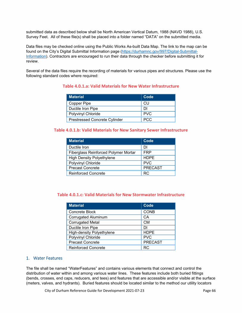
City of Durham Reference Guide for Development 2021‐07‐23 Page 66
submitted data as described below shall be North American Vertical Datum, 1988 (NAVD 1988), U.S. Survey Feet. All of these file(s) shall be placed into a folder named “DATA” on the submitted media.
Data files may be checked online using the Public Works As-built Data Map. The link to the map can be found on the City’s Digital Submittal Information page (https://durhamnc.gov/997/Digital-Submittal-Information). Contractors are encouraged to run their data through the checker before submitting it for review.
Several of the data files require the recording of materials for various pipes and structures. Please use the following standard codes where required:
Table 4.0.1.a: Valid Materials for New Water Infrastructure
Material Code
Copper Pipe CU Ductile Iron Pipe DI Polyvinyl Chloride PVC
Prestressed Concrete Cylinder PCC
Table 4.0.1.b: Valid Materials for New Sanitary Sewer Infrastructure
Material Code
Ductile Iron DI Fiberglass Reinforced Polymer Mortar FRP High Density Polyethylene HDPE Polyvinyl Chloride PVC Precast Concrete PRECAST Reinforced Concrete RC
Table 4.0.1.c: Valid Materials for New Stormwater Infrastructure
Material Code
Concrete Block CONB Corrugated Aluminum CA Corrugated Metal CM Ductile Iron Pipe DI High-density Polyethylene HDPE Polyvinyl Chloride PVC Precast Concrete PRECAST Reinforced Concrete RC
1. Water Features
The file shall be named “WaterFeatures” and contains various elements that connect and control the distribution of water within and among various water lines. These features include both buried fittings (bends, crosses, end caps, reducers, and tees) and features that are accessible and/or visible at the surface (meters, valves, and hydrants). Buried features should be located similar to the method our utility locators

City of Durham Reference Guide for Development 2021‐07‐23 Page 67
use: a paint dot is placed on the pavement at the approximate location of the feature and then surveyed location is taken at the paint mark.
Water line locations (“WATERLINE” type in the table below) are required only if the water line curves. These locations will be surveyed at 25 foot stations along the length of the water line.
Each line of the file shall contain the following information:
b. ID, Type, Easting, Northing, Elevation, Description (all on first line of the file) c. Where:
1. ID - A unique ID number assigned to each feature noted on the as-built plan and profile sheets (e.g. GV-1, HYD-1, etc.)
2. Type - The type of feature. Provide the following codes as indicated in the table below:
Table 4.0.2: Water Features Descriptions
Feature Description Type
Air Release Valve ARV
Backflow Preventer BFP
Bend BEND
Blow Off BLOWOFF
Cross CROSS
End Cap CAP
Fire Department Connection FDC
Fire Hydrant HYDRANT
Post Indicator Valve PIV
Reducer/Increaser REDUCER
Tee/Tapping Sleeve TEE
Water Valve VALVE
Water Line WATERLINE
Water Meter METER
3. Easting – East coordinate value (+/- 2.0’ if buried, +/- 0.1’ otherwise) 4. Northing – North coordinate value (+/- 2.0’ if buried, +/- 0.1’ otherwise) 5. Elevation – Elevation, collected as follows: (+/- 2.0’ if buried, +/- 0.1’ otherwise)
Table 4.0.3: Water Feature Elevation Locations
Feature Type Elevation Location
BEND/BLOWOFF/CROSS/END CAP/REDUCER/TEE
Surface, at the mark that indicates the approximate location of the buried feature.
HYDRANT Top of the fire hydrant.
METER/VALVE Center of the access structure.
WATERLINE Surface, at the mark that indicates the approximate location of the buried line, at 25 foot stations. Only required if a water line is curved.
6. Description - The description of the item for the feature; encoded as follows:
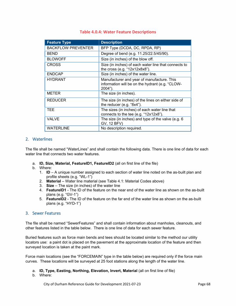
City of Durham Reference Guide for Development 2021‐07‐23 Page 68
Table 4.0.4: Water Feature Descriptions
Feature Type Description
BACKFLOW PREVENTER BFP Type (DCDA, DC, RPDA, RP)
BEND Degree of bend (e.g. 11.25/22.5/45/90).
BLOWOFF Size (in inches) of the blow off.
CROSS Size (in inches) of each water line that connects to the cross (e.g. “12x12x8x8”).
ENDCAP Size (in inches) of the water line.
HYDRANT Manufacturer and year of manufacture. This information will be on the hydrant (e.g. “CLOW-2004”).
METER The size (in inches).
REDUCER The size (in inches) of the lines on either side of the reducer (e.g. “8x4”).
TEE The sizes (in inches) of each water line that connects to the tee (e.g. “12x12x8”).
VALVE The size (in inches) and type of the valve (e.g. 6 GV, 12 BFV)
WATERLINE No description required.
2. Waterlines
The file shall be named “WaterLines” and shall contain the following data. There is one line of data for each water line that connects two water features.
a. ID, Size, Material, FeatureID1, FeatureID2 (all on first line of the file) b. Where:
1. ID – A unique number assigned to each section of water line noted on the as-built plan and profile sheets (e.g. “WL-1”)
2. Material – Water line material (see Table 4.1: Material Codes above) 3. Size – The size (in inches) of the water line 4. FeatureID1 - The ID of the feature on the near end of the water line as shown on the as-built
plans (e.g. “GV-1”) 5. FeatureID2 - The ID of the feature on the far end of the water line as shown on the as-built
plans (e.g. “HYD-1”)
3. Sewer Features
The file shall be named “SewerFeatures” and shall contain information about manholes, cleanouts, and other features listed in the table below. There is one line of data for each sewer feature.
Buried features such as force main bends and tees should be located similar to the method our utility locators use: a paint dot is placed on the pavement at the approximate location of the feature and then surveyed location is taken at the paint mark.
Force main locations (see the “FORCEMAIN” type in the table below) are required only if the force main curves. These locations will be surveyed at 25 foot stations along the length of the water line.
a. ID, Type, Easting, Northing, Elevation, Invert, Material (all on first line of file) b. Where:

City of Durham Reference Guide for Development 2021‐07‐23 Page 69
1. ID – If the feature is a manhole then the number as shown on the as-built drawings (e.g. “MH-1”). If feature is a clean out then a lot number or street address (e.g. “LOT10” or “123 Street Name”).
2. Type – The feature type, coded according to the following table:
Table 4.0.5: Sanitary Sewer Features Descriptions
Feature Description Type
Clean Out CLEANOUT
Drain DRAIN
Force Main Valve FMVALVE
Force Main Tee FMTEE
Force Main Bend FMBEND
Force Main FORCEMAIN
Grease Trap GREASETRAP
Manhole MANHOLE
Oil-Water Separator OWS
3. Easting – East coordinate value (+/- 0.1’). 4. Northing – North coordinate value (+/- 0.1’). 5. Elevation – Rim elevation at the center of cover (+/- 0.1’).
Table 4.0.6: Sanitary Sewer Features Elevations Locations
Feature Type Elevation Location
CLEANOUT Surface adjacent to the cleanout.
DRAIN Center of the drain grate.
FMVALVE Center of the access structure.
FMTEE/FMBEND Surface, at the mark that indicates the approximate location of the buried feature.
FORCEMAIN Surface, at the mark that indicates the approximate location of the buried main, at 25 foot stations. Only required if a force main curves.
GREASETRAP/OWS Center of the structure
MANHOLE Rim of the manhole.
6. Invert – Invert elevation (+/- 0.1’, required only for manholes) 7. Material – Construction material (see Table 4.1: Material Codes above)
4. Sewer Pipes
The file shall be named “SewerPipes” and shall contain the following data. There is one line of data for each sewer pipe.
If the pipe is a force main, values for Size, Material, USId, and DSId only need to be provided.

City of Durham Reference Guide for Development 2021‐07‐23 Page 70
a. ID, Size, Material, USId, DSId, USI, DSI, Slope, Length (all on first line of the file) b. Where:
1. ID – A sequential pipe number as noted on the as-built drawings (e.g. “SSP-1”). 2. Size – Inside pipe diameter (inches). 3. Material – Pipe material (see Table 4.1: Material Codes above). 4. USId – Upstream manhole number as shown on the as-built drawings (e.g. “MH-1”). 5. DSId - Downstream manhole number as shown on the as-built drawings (e.g. “MH-2”). 6. USI – Invert elevation at the upstream end. 7. DSI – Invert elevation at the downstream end. If downstream end is a drop connection provide
both elevations separated by a slash (e.g. 344.10/340.03). 8. Slope – The as-built grade of the pipe, expressed as a percentage and carried out to two
decimal places. 9. Length – The length (in linear feet) of the pipe as indicated on the as-built mylar carried out two
decimal places.
5. Stormwater Features
The file shall be named “StormwaterFeatures.” A storm water feature is either a combination inlet, curb inlet, drop/yard/grate inlet (cast iron grate cover with slotted openings), manhole, riser pipe, or slab inlet (solid concrete cover, supported on the corners with side flow entry). There is one line of data for each storm water structure.
a. ID, Type, Easting, Northing, Elevation, Invert, Material (all on first line of the file) b. Where:
1. ID – Structure number as shown on the as-built drawings (e.g. “SWMH-1”, “CB-2”, “YI-4”,”DI-3”). 2. Type – Type of storm water feature, to be encoded according to the following table:
Table 4.0.7: Stormwater Features Description
Feature Description Type
Frame and Grate Inlet COMBINATION INLET
Curb Inlet (frame, no grate) CURB INLET
Drop/Grate/Yard Inlet (grate flush with ground)
DROP INLET
End Section END SECTION
Headwall HEADWALL
Junction Box JUNCTION BOX
Manhole MANHOLE
Pond Outlet Riser RISER PIPE
Slab Inlet/Open Throat Catch Basin SLAB INLET
Weir Box WEIR BOX
3. Easting – East coordinate value (+/- 0.1’). 4. Northing – North coordinate value (+/- 0.1’). 5. Elevation – Elevation, collected as follows: (+/- 0.1’).
Table 4.0.8: Stormwater Features Elevations Locations
Feature Type Elevation Location
COMBINATION INLET Back of curb, center of box
CURB INLET Back of curb, center of box
DROP INLET Center of grate

City of Durham Reference Guide for Development 2021‐07‐23 Page 71
Feature Type Elevation Location
END SECTION Top of end section
HEADWALL Center of the headwall
JUNCTION BOX Center of cover
MANHOLE Center of cover
RISER PIPE Top of the riser
SLAB INLET Top of slab, center of box
WEIR BOX Top center of box
6. Invert – The invert elevation. 7. Material – Construction material (see Table 4.1: Material Codes above).
6. Stormwater Pipes
Stormwater Pipes – The file shall be named “StormwaterPipes” and shall contain the following data. There is one line of data for each stormwater pipe.
a. ID,Size, Material, USId, DSId, USI, DSI, Slope, Length (all on first line of the file) b. Where:
1. ID – A sequential pipe number as noted on the as-built drawings (e.g. “SWP-1”). 2. Size – Pipe diameter (inches). Non-circular pipe sizes can be indicated with two dimension
values separated by an “X” (e.g. “4x6”). 3. Material – Pipe material (see Table 4.1: Material Codes above). 4. USId – Upstream feature ID number as shown on the as-built drawings (e.g. “SWMH-1”). 5. DSId - Downstream feature ID number as shown on the as-built drawings (e.g. “CB-2”). 6. USI – Invert elevation at the upstream end. 7. DSI – Invert elevation at the downstream end. 8. Slope – The as-built grade of the pipe, expressed as a percentage carried out to two decimal
places. 9. Length – The length (in linear feet) of the pipe as indicated on the as-built mylar and carried out
to two decimal places.
E. Example Project File
A “Frequently Asked Questions” section and an “Example Project File” of the as-builts digital submittals are available on the City’s Digital Submittal Information page (https://durhamnc.gov/997/Digital-Submittal-Information).
4.0.5 Approved As‐built Drawings Submittal
A. Approved As‐built Drawings Submittal
After the as-built drawings have been reviewed and approved provide:
1. One set of reproducible double matte Mylar with corrections and the As-built Certification Statements both signed and sealed by a registered North Carolina Professional Engineer and/or a Professional Land Surveyor
2. Marked-up set (redlines) 3. Electronic submittal (see Section 4.4 above) 4. Request for Infrastructure Acceptance Pursuant to Durham City Code 62-126 Form

City of Durham Reference Guide for Development 2021‐07‐23 Page 72
B. As‐built Drawings Construction Security
A construction security, in the form of a bank check with an escrow agreement, can be provided in lieu of the final as-built Mylar plans and digital information after paper as-built drawings have been approved. The amount of the construction security will depend on the size of the project. For a single phase of a subdivision the construction security is a minimum of $5,000. The amount may be more depending on the amount of infrastructure constructed. A Construction Security Management fee shall be paid at time of the submittal of the construction security.
Construction Security Management fee = Escrow Amount x 0.2% ($100 minimum) + 4% technology surcharge fee

City of Durham Reference Guide for Development 2021‐07‐23 Page 73
Section 4.1: City of Durham Video Inspection
Submittal and Review Process
4.1.1 When is Video Inspection Required?
Video Inspection is required for permitted storm drainage and sanitary sewer pipes and structures as follows:
Single Family Residential o Storm drainage pipes and structures installed within an existing or proposed public City of
Durham or private street (not private access/common area or parking lots). o Storm drainage pipes and structures installed within a storm drainage easement. o Sanitary sewer pipes and structures installed within an existing or proposed public street
(City of Durham or NCDOT) and/or public sanitary sewer easement. o Private sanitary sewer mains.
Multi-Family Residential o Storm drainage pipes and structures installed within an existing or proposed public City of
Durham or private street (not private access/common area or parking lots). o Storm drainage pipes and structures installed within a storm drainage easement. o Sanitary sewer pipes and structures installed within an existing or proposed public street
(City of Durham or NCDOT) and/or public sanitary sewer easement. o Private sanitary sewer mains.
In-Fill Lots o Storm drainage pipes and structures installed within an existing or proposed public City of
Durham or private street (not private access/common area or parking lots). o Storm drainage pipes and structures installed within a storm drainage easement that
conveys drainage from an adjacent property. o Sanitary sewer pipes and structures installed within an existing or proposed public street
(City of Durham or NCDOT) and/or public sanitary sewer easement. All Other Projects
o Storm drainage pipes and structures installed within an existing or proposed public City of Durham or private street (not private access/common area or parking lots).
o Storm drainage pipes and structures installed within a storm drainage easement that conveys drainage from an adjacent property.
Sanitary sewer pipes and structures installed within an existing or proposed public street (City of Durham or NCDOT) and/or public sanitary sewer easement.
Please note the following exceptions: *City of Durham Public Works Engineering will require video inspection of storm drainage and sanitary sewer for any scenario not listed above. *Video Inspection is not required by the City of Durham for storm drainage installed within NCDOT ROW. *Video Inspection is not required by the City of Durham for Durham County maintained sanitary sewer.
4.1.2 Video Inspection Review Process
The Engineer of Record shall submit the Video Inspection submittal packages to the Development Services Center online portal (https://dsc.durhamnc.gov/239/2504/Video-Inspection-submittal-portal?activeLiveTab=widgets). A comment letter will be issued from Public Works Engineering after the review is complete.
City of Durham Reference Guide for Development 2021‐07‐23 Page 74
The submittal package shall consist of:
1st Video Inspection Submittal o Video Inspection Review Fee (1st Review only) o Video Inspection Submittal Checklist o Sanitary and/or Storm Drainage Video Inspection(s) o As-built PDF highlighting pipes and structures from Video Inspection(s) o Video Inspection Contractor’s reports
Post-Repair Video Inspection Submittal o Video Inspection Submittal Checklist o Sanitary and/or Storm Drainage Video Inspection(s) o As-built PDF highlighting pipes and structures from Video Inspection(s) o Video Inspection Contractor’s reports o Engineer of Record’s Repair Evaluation
Once received, video inspection submittals will be evaluated to ensure items listed above are included. Submittals that do not include the applicable items listed above will not be accepted for review and will be returned to applicant.
The sanitary sewer video inspection submittals will be reviewed within 10 business days of receipt of a complete video inspection submittal. The storm drainage video inspection submittals will be reviewed within 45 business days of receipt of a complete video inspection submittal.
Public Works Engineering will review the video inspections and provide the Engineer of Record with any deficiencies identified during the review. The Engineer of Record must submit to Public Works Engineering recommendations to address the deficiencies. Once the repairs are approved and completed, post-repair video inspection will be required. The Engineer of Record must review the post-repair video inspection to determine if the repairs are complete based on the repair recommendation. A Post-Repair Video Inspection Submittal must be provided to Public Works Engineering with the items listed above. Public Works Engineering will review the post-repair video inspection submittal and respond with any further comments.
Video Inspections for utilities in roadways shall occur after the stone subbase is compacted and setup, but not less than 30 days after installation and backfill. Video Inspections for utilities outside of roadways shall be no sooner than 300 days after installation and backfill to finish grade. The Video Inspection submittal shall be submitted within 60 days of the video inspection being completed.
Prior to scheduling a utility walkthrough with Public Works Engineering Inspections the following Video Inspection Submittal condition must be met:
1. Storm Drainage and Sanitary Sewer Video Inspection Submittal must be received and accepted for review by Public Works Engineering
4.1.3 Video Inspection Review Fees
The following fees are due at the 1st submittal for the review of sanitary sewer and/or storm drainage video inspections:
1. Sanitary Sewer - $1.00 per linear foot 2. Storm Drainage - $1.00 per linear foot
Submittals will not be accepted if the appropriate fees are not paid.

City of Durham Reference Guide for Development 2021‐07‐23 Page 75
4.1.4 Video Inspection Submittal Requirements
1. Video Inspection a. All video inspections shall meet all NASSCO requirements for the video inspection of pipes and
structures. b. Per NASSCO requirements all video inspections must be performed in the presence of a
NASSCO certified individual. All Video Inspection Submittal Checklists must include the contractor’s NASSCO certification number. Video inspections that are not performed in the presence of a NASSCO certified individual will not be accepted for review. Additionally, video inspections will not be accepted for review if the NASSCO certification number is not provided.
c. Video inspections shall be performed no sooner than 30 days and no later than 60 days from the date of installation of the associated infrastructure.
2. Utility Map PDF a. All Video Inspection submittals shall include an as-built utility map in PDF format that highlights
the pipes and structures included in the video inspection. b. Individual maps are required for both storm drainage and sanitary sewer. Structure numbers,
pipe sizes, pipe material, and pipe diameter shall be labeled on the map. The Video Inspection labels shall match the pipe and structure information provided on the as-built map.
c. The utility maps shall include all applicable phase lines. d. Street names shall be labeled on the utility maps.
3. Video Inspection Reports a. Video Inspection submittals shall include video inspection reports from the contractor. b. Video Inspection reports shall be formatted to meet the PACP, MACP, and LACP standards
established by NASSCO. Video inspections and reports shall be coded per NASSCO PACP, MACP, and LACP standards.
4. Pipe and Structure Evaluation Requirements a. All installed storm drainage and sanitary sewer, pipes and structures, must meet all established
Public Works and Water Management standards. b. Storm Drainage pipe and structure, evaluations and repair recommendations, must meet the
following industry standards: i. American Concrete Pipe Association – Post Installation Evaluation and Repair of Installed
Concrete Pipe ii. ASTM C1840 - Standard Practice for Inspection and Acceptance of Installed Reinforced
Concrete Culvert, Storm Drain, and Storm Sewer Pipe iii. AASHTO R73-16 – Standard Practice for Evaluation of Precast Concrete Drainage
Structures c. Sanitary Sewer pipe and structure, evaluations and repair recommendations, must meet all
standards established by Water Management. i. Epoxy lined sanitary sewer pipe must be free of all lining defects prior to acceptance.
d. Material and/or Manufacturer submittals will be required by Public Works and Water Management prior to the installation of any proposed repairs.

City of Durham Reference Guide for Development 2021‐07‐23 Page 76
Section 5.0: Water Supply/Distribution
This section provides guidelines for the design of water main extensions for the City of Durham water distribution system. As a minimum, the Developer/Engineer shall satisfy the requirements contained herein and the City of Durham Construction Water and Sewer Details and Specification. See also Section 2 and Section 3.
5.1 Sizing of Water Mains
A. Source
If the proposed development has 100 or more dwellings the site shall have no less than two public water main feeds serving the site. Existing mains greater than 16-inches in diameter are considered transmission mains and no connection of any kind to these mains is allowed. Developers must use mains 16-inches in diameter and less as the source location.
B. Size
The size of the waterlines is determined by:
Fire flow plus domestic demand for the site (see also C. Pressure) Future growth beyond the site Department of Water Management
The standard pipe diameter for public and private lines are 4-inch, 6-inch, 8-inch, 12-inch, 16-inch (refer to the City of Durham Water and Sewer Specifications). In addition, 10-inch diameters may be used for private lines.
Waterlines 2” in diameter or greater may require a water distribution permit at the discretion of the Public Works Department and in accordance with all applicable local, state and federal regulations. Waterlines 2” in diameter or greater are eligible for acceptance for maintenance by the City of Durham as permitted distribution mains provided they meet all other criteria for water main acceptance by the City of Durham described herein.
C. Pressure
Water mains shall be sized to provide a minimum system pressure of 20-pounds per square inch (psi) during peak system demands plus fire demand. In certain areas of Durham, or for multi-story buildings, there is a potential for having lower water pressure and a private booster pump may be needed to assure adequate service to the site. If it is determined that the proposed development has a potential of being in one of these lower pressure areas, complete and submit the "Potential Low Water Pressure Acknowledgement" in Section 13.0, Forms, as directed by the City of Durham Engineering Division. If higher pressures are required or desired, it is the responsibility of the water customer to provide the necessary booster pumping equipment and facilities. If booster pumps are used contact the Engineering Division and Cross-Connection Control for requirements (back-flow, etc.). The booster pumps should be clearly noted on the construction plans if they are proposed. The peak system demands are to include: peak domestic demand + fire protection system (sprinkler) demand + fire flow demand.
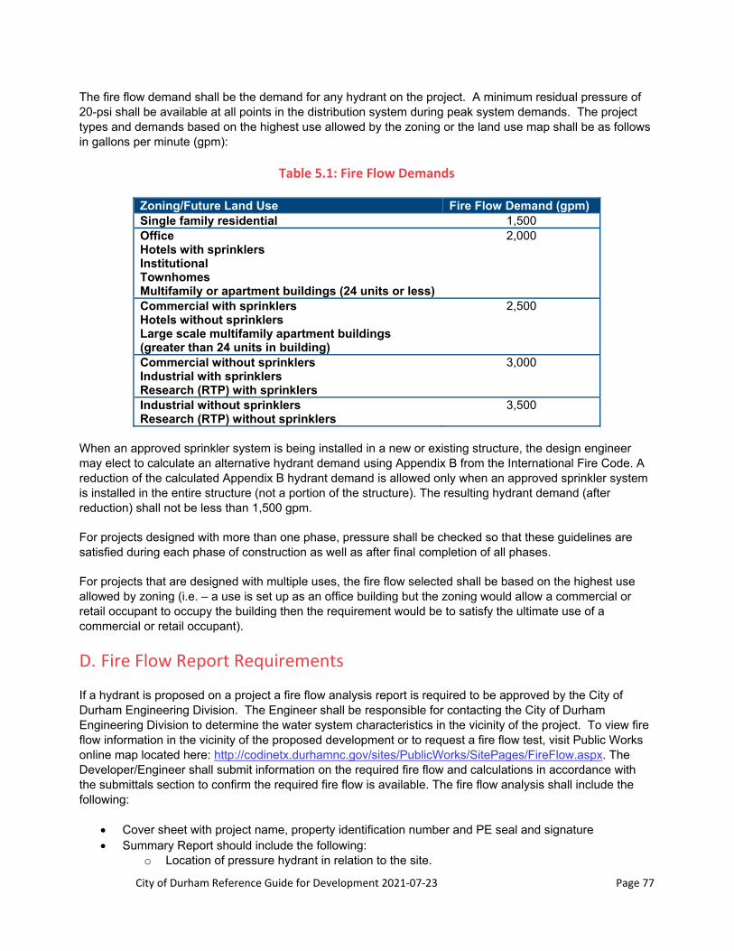
City of Durham Reference Guide for Development 2021‐07‐23 Page 77
The fire flow demand shall be the demand for any hydrant on the project. A minimum residual pressure of 20-psi shall be available at all points in the distribution system during peak system demands. The project types and demands based on the highest use allowed by the zoning or the land use map shall be as follows in gallons per minute (gpm):
Table 5.1: Fire Flow Demands
Zoning/Future Land Use Fire Flow Demand (gpm) Single family residential 1,500 Office Hotels with sprinklers Institutional Townhomes Multifamily or apartment buildings (24 units or less)
2,000
Commercial with sprinklers Hotels without sprinklers Large scale multifamily apartment buildings (greater than 24 units in building)
2,500
Commercial without sprinklers Industrial with sprinklers Research (RTP) with sprinklers
3,000
Industrial without sprinklers Research (RTP) without sprinklers
3,500
When an approved sprinkler system is being installed in a new or existing structure, the design engineer may elect to calculate an alternative hydrant demand using Appendix B from the International Fire Code. A reduction of the calculated Appendix B hydrant demand is allowed only when an approved sprinkler system is installed in the entire structure (not a portion of the structure). The resulting hydrant demand (after reduction) shall not be less than 1,500 gpm.
For projects designed with more than one phase, pressure shall be checked so that these guidelines are satisfied during each phase of construction as well as after final completion of all phases.
For projects that are designed with multiple uses, the fire flow selected shall be based on the highest use allowed by zoning (i.e. – a use is set up as an office building but the zoning would allow a commercial or retail occupant to occupy the building then the requirement would be to satisfy the ultimate use of a commercial or retail occupant).
D. Fire Flow Report Requirements
If a hydrant is proposed on a project a fire flow analysis report is required to be approved by the City of Durham Engineering Division. The Engineer shall be responsible for contacting the City of Durham Engineering Division to determine the water system characteristics in the vicinity of the project. To view fire flow information in the vicinity of the proposed development or to request a fire flow test, visit Public Works online map located here: http://codinetx.durhamnc.gov/sites/PublicWorks/SitePages/FireFlow.aspx. The Developer/Engineer shall submit information on the required fire flow and calculations in accordance with the submittals section to confirm the required fire flow is available. The fire flow analysis shall include the following:
Cover sheet with project name, property identification number and PE seal and signature Summary Report should include the following:
o Location of pressure hydrant in relation to the site.
City of Durham Reference Guide for Development 2021‐07‐23 Page 78
o Statement of required fire flow for the project. Briefly describe the project and indicate current zoning of the parcel.
o Statement of the following: “The (name of project) project with (required fire flow) gpm fire flow, (required peak domestic demand) gpm peak domestic flow and (sprinkler flow demand from sprinkler designer) gpm sprinkler flow provides (lowest residual pressure in system) psi residual flow at the critical node (lowest residual pressure system node). This (meets)/ (does not meet) the City of Durham fire flow requirements.
Schematic drawing with pipe system layout referencing nodes and pipes. Map (to scale) of location of test hydrant (pressure) and the location of the site clearly indicated.
List original water system characteristics as provided by the City noting date, location, flow hydrant, pressure hydrant and Q20 flow available.
Pipe and node report indicating pipe sizes, lengths, frictions factor, minor losses and appropriate elevations and demands. Provide all references for minor loss factors and if a range is given state the value you are using. (Use C=120 for new pipes and C=110 for existing pipes)
Static condition indicating only new domestic demand. (Provide all references and calculations for domestic peak demands)
Separate fire flow models from each hydrant to indicate each hydrant is capable of providing the fire flow demand while concurrently providing peak domestic and fire protection system demand.
If the fire flow analysis does not meet the minimum City of Durham requirements then the consultant shall contact the City of Durham Engineering Division for further instruction, which may include additional offsite/onsite improvements.
NOTE: At the successful completion of the waterline testing phase the City of Durham Engineering Division may elect to flow test some of the hydrants to obtain data to compare against the fire flow analysis. If the flow data is inconsistent with the analysis, the design consultant and developer will be contacted to remedy the situation.
E. Water Main Material
All waterlines shall be ductile iron and services to be copper to the water meter or to the property line (meeting AWWA standards).
5.2 Water Main Location
A. Depth
1. Water mains shall be designed with a minimum of three feet of cover or as directed by the Engineering Division from the top of the ground to the crown of the pipe.
2. For proposed waterlines along existing roads, road centerline or edge of pavement will be required on profile in addition to the top of ground above the waterline (Cross-sections of the road from centerline of roadway to right-of-way will be required at 100-foot intervals in addition to waterline profiles). Additional cross-sections may be required depending on the project. Over long distances (greater than 1000-feet) the number of cross-sections may be reduced with the City of Durham Engineering Division approval.
B. Location
Water mains are normally located:
Under pavement

City of Durham Reference Guide for Development 2021‐07‐23 Page 79
On the north and east sides of streets Additional waterline stubs will be required by the City of Durham Engineering Division. At a
minimum, additional stubs will be required at all intersecting roadways or rights-of – way. 10-feet from centerline of street (not to be under the curb and gutter section) Shall be 18-inches above or 10-feet horizontal from sanitary sewer lines. If unable to maintain
either of these separations both lines shall be made of ductile iron for a minimum of 10-feet beyond the crossing with the joint being centered at the point of intersection.
Shall be 12-inch separation from storm sewer lines and other utilities.
C. Easements, Encasements and Right of Way
1. All public water mains shall be located within a street right-of-way to allow City personnel access to the main for maintenance and repair. Water lines that are eligible for recommendation for acceptance for ownership by the City of Durham include all water mains located within City of Durham streets rights-of-way or North Carolina DOT rights-of-way. Water lines located in private streets, public or private access common areas, public alleys or private alleys shall not be eligible for recommendation for acceptance by the City of Durham without a Reference Guide for Development Alternative Design approved by the Department of Water Management. The Alternative Design must be approved prior to approval of the subject site plan and would be processed as a Tier 2 request. This requirement does not apply to City funded projects.
2. Private water main easements shall be no less than 25-feet. Private water lateral easements shall be no less than 15-feet and may be greater.
3. No landscaping or earthwork is allowed in existing waterline easements. No landscaping is allowed in proposed waterline easements and all earthwork must be completed before waterline is installed.
4. Encasements are required for bored crossings and railroad right-of-way. Refer to the City of Durham Water and Sewer Construction Specifications for pipe encasement details. See the table below for encasement sizes. The pipe is required to have restrained joints under the road area. The jack & bore pit size shall be shown and labeled on the construction plans. NCDOT and the railroads may have more stringent requirements.
Table 5.2: Sizing Table for Carrier Pipe and Casing Pipes
Nominal Carrier Pipe Size (Inches)
Steel Casing Pipe Size (Inches) Railroad Crossing Road Crossing
Outside Diameter Wall Thickness Outside Diameter Wall Thickness 3 and Under 12.75 0.188 6.625 0.250 4 12.75 0.188 8.625 0.250 6 12.75 0.188 12.75 0.250 8 16 0.219 16 0.250 10 20 0.281 20 0.250 12 24 0.312 24 0.250 14 28 0.375 28 0.312 16 30 0.406 30 0.312 18 36 0.469 36 0.375 20 42 0.562 42 0.500 24 42 0.562 42 0.500

City of Durham Reference Guide for Development 2021‐07‐23 Page 80
D. Construction
Contact Durham Engineering Inspections for a pre-construction conference no less than 48 hours before starting construction.
All waterlines are to be visually inspected by the Public Works Engineering Inspectors before backfilling.
Once a waterline has completed all steps for acceptance established by the Public Works Department for testing and acceptance, the waterline must either have an active water meter or continuously turn over via a hydrant meter rented from the City within seven calendar days of the last passing bacteriological test. Flow rate and location of the meter shall be approved by the Department of Water Management prior to opening the valve that feeds the waterline. Any waterline that has sat for longer than seven days must be re-flushed and re-tested prior to being placed in service.
5.4 Fire Hydrants
1. The spacing and location of fire hydrants shall meet the current provisions of the North Carolina Fire Prevention Code in addition to those provisions set forth in Items 2 through 16 below. Adequate spacing of fire hydrants shall be determined by the Fire Official. Spacing of fire hydrants around buildings and facilities shall take into account natural and man-made barriers, including steep terrain, walls, fences, waterways, culverts and vehicle parking areas. Distance measurements shall be made along the centerline of fire equipment access roadways where roadways occur.
2. Fire hydrants shall be located so that they shall be installed on a 6-inch branch line and shall be equipped with a gate valve for isolation purposes. The hydrant isolation valve shall be located directly adjacent to the water main and shall be inside the pavement when possible.
3. Hydrants shall be oriented so that large diameter connection faces fire apparatus access. 4. Hydrants shall be no closer than 10-feet from the PC or PT of any intersection, including non-
residential driveways. 5. Hydrants are to be placed 18-inches to back of curb. 6. Hydrants are 1-foot within the right-of-way on strip paved streets. 7. In residential and multi-family areas:
Fire hydrants shall be located near each street intersection. Maximum spacing of hydrants in single-family housing areas shall not exceed 500-feet. The
hydrant spacing distance shall be the horizontal distance as measured along the centerline of the street.
Hydrants shall be located near the entrance of each cul-de-sac bulb where the street leading to the bulb is greater than 500-feet in length from the street centerline to the cul-de-sac radius point.
Hydrants shall be on same side as all Fire Department Connections. 8. In all commercial, business, institutional, office, shopping center, mobile home, and industrial areas:
Fire hydrants shall be located at each street intersection. Maximum spacing between hydrants shall not exceed 500-feet. The hydrant spacing distance shall
be the horizontal distance as measured along the centerline of the street. 9. For projects designed with more than one phase, hydrants shall be located so that these guidelines are
satisfied during each phase of construction as well as after final completion of all phases. 10. Hydrants shall be situated at locations which enable fire apparatus to pass other fire apparatus which
have stopped to connect to the hydrant (driveway width 20-foot minimum). 11. A hydrant shall be installed no less than 6-feet nor more than 50-feet (lineal) from any and all Fire
Department Connections (FDC). This requirement does not apply to FDC’s serving the apartment buildings of group apartment housing as defined in Durham City Code Section 70-22(a)(1).

City of Durham Reference Guide for Development 2021‐07‐23 Page 81
12. Landscape plantings (when fully grown) or other vertical projections greater than 6-inches in height shall not encroach upon any fire hydrant within a 3-foot radius and not obscure view of hydrant upon approach.
13. Hydrants shall be located a minimum of 40-feet from any building walls. Fire Official can reduce this requirement.
14. Hydrants shall be situated to enable fire equipment to first pass a fire hydrant before reaching any structure or hazard associated with a site.
15. Fire hydrants located on private property adjacent to a site may be considered when an off-street access roadway of sufficient width and height between the two sites is established by an easement and approved by the Fire Official.
16. Fire Hydrants located - Across streets or roadways with median dividers, or Across streets or roadways with 4 or more lanes, or Across streets or roadways with an average daily traffic count of more than 30,000 vehicles from a
site shall not be considered accessible and useable for purposes of this section.
5.5 Fire Department Connections (FDC)
These fittings, typically associated with a sprinkler/standpipe system within a building, shall be located no closer than 6-feet or greater than 50-lineal feet of a fire hydrant. In all instances, these fittings shall be located on the same side of the travel lane. Both hydrant and connection shall be accessible along the roadway fronting the building or along the roadway approaching the building. This requirement does not apply to FDC’s serving the apartment buildings of group apartment housing as defined in Durham City Code Section 70-22(a)(1).
Contact Fire Department for requirements for buildings with standpipe systems.
5.6 Valves
A. Type
1. Valves 12-inch and below require a valve box. 2. Valves 16-inch are required to be in 8-foot diameter manholes. 3. Gate valves are to be used up to and including 12-inch diameter water lines. 4. Valves controlling fire protection system water supplies, where located on private property shall be in
accordance with the North Carolina Fire Prevention Code. Post indicator valves (PIV), located 40-feet from building walls when possible, shall be installed unless other valve arrangements are approved by the Fire Official.
B. Locations
1. Each intersection of water mains shall have one less main line valve than the number of intersecting pipes as stated in 15A NCAC 18C .0907. The following shall also be followed dependent upon the type of installation: a. Public or private water mains and fire loops
i. If existing valve(s) are within 50 feet of the proposed junction, valve(s) do not need to be installed on the existing water main or fire loop. Install new valve(s) within 50 feet of junction on proposed water main or fire loop.

City of Durham Reference Guide for Development 2021‐07‐23 Page 82
ii. If existing valve(s) are more than 50 feet from the proposed junction, install valve(s) on the existing water main or fire loop. Install new valve(s) within 50 feet of junction on proposed and existing water mains or fire loops. 1. When an existing valve is present on the existing main but located more than 50 feet from
the proposed junction, the new valve(s) installed shall be placed on the existing main on the side opposite of the closest existing valve on the existing main.
b. Domestic and fire services ≥ 2-inch i. If an existing valve is within 50 feet of the proposed junction, an additional valve on the existing
water main is not required. Install a new valve on the proposed service. ii. If and existing valve is greater than 50 feet from the proposed junction, install a valve on the
existing water main. Install a new valve on the existing main within 50 feet of the proposed service and on the service. 1. When an existing valve is present on the existing main but located more than 50 feet from
the proposed junction, the new valve cut in shall be placed on the existing main on the side opposite of the closest existing valve on the existing main.
c. Domestic and fire services < 2-inch i. Domestic and fire services less than 2-inches in diameter do not require installation of a valve
on the existing water main. Install a new valve on the proposed service. 2. Each intersection of hydrant branch to water main shall have one valve on the hydrant branch. 3. For all private water systems, a valve shall also be located at the right-of-way line to delineate public
and private maintenance responsibilities. 4. Because insertion valves do not meet AWWA C509, insertion valves will not be accepted in lieu of a
cut-in valve on the existing water main. 5. Tapping sleeves and valves may not be used in lieu of the above requirements.
C. Straight Runs
Main line valves located in straight runs of pipe shall be spaced as follows:
Table 5.3: Valve Spacing
Main Size Maximum Spacing 4-inch 400-feet 6-inch 600-feet 8-inch 900-feet 12-inch 1000-feet 16-inch 1000-feet
D. Tapping Sleeves
1. A City of Durham Engineering Division Inspector is to be present at all taps to water mains prior to the tap being made unless other arrangements have been made with the City Inspector.
2. Wet tap with a tapping sleeve and valve is permitted (refer to the City of Durham Water and Sewer Standards and Specifications).
3. Same size taps are only allowed on an 8-inch line and smaller. Any larger same size connection requires installing a tee and valve(s).
4. If a tapping valve is 12-inch or larger, the valve and the tapping sleeve are to be located within one manhole. Cut in tees with sleeves are required for 12-inch by 12-inch same size taps or larger.
City of Durham Reference Guide for Development 2021‐07‐23 Page 83
E. Terminating Lines
1. For 12-inch by 16-inch taps, the valve and tapping sleeve are to be located in a 5-foot diameter manhole.
2. Piping 12-inch and greater shall extend 3 pipe joints beyond end line valve. Piping less than 12-inches in diameter shall extend 2 pipe joints beyond end line valves.
5.7 Blow‐offs
A 2-inch blow-off assembly shall be installed on all dead end mains and, as directed by the Engineering Division, at elevated points along the water main. Fire hydrants are not considered as blow-offs for public lines.
5.8 Pressure‐reducing Valves
Pressure-reducing valves for water services shall be installed in accordance with current City of Durham Plumbing Code.
5.9 Services and Meters
1. The City shall maintain water service lines up to and including 2” in diameter up to the ROW line when the water service line is connected to a public water line that has been accepted by the City of Durham. This maintenance shall be limited to service lines that serve single family homes, duplexes and triplexes and shall include the maintenance of the meter box, meter setter, meter lid and water meter. The private property owner shall maintain the connection to the meter setter or yoke as well as the water service between the setter and the private residence.
2. The city side of the proposed meter box for all water meters for single family homes, duplexes or triplexes must be located within 1’ of City ROW or DOT ROW if acceptance of the service line for City maintenance is proposed. Meters proposed to be located within ditch lines or driveways shall require a Reference Guide for Development Alternative Design approved by the Department of Water Management prior to installation. Meters located within sidewalks require a Reference Guide for Development Alternative Design approved by the Public Works Department prior to installation and require H-20 rated boxes.
3. The City shall maintain the water meter and gasket between the city meter and setting assembly for all meters connected to private water mains or private services. The City shall not maintain meter boxes, setting assemblies or other meter appurtenances on private property more than 1’ from the ROW and easements.
4. Two meters shall not share one service line unless one meter is for irrigation purposes. Each domestic meter shall have its own service line from the main.
5. Water meters shall be accessible to city personal at all times. 6. Water line services shall be copper or ductile iron from the main to the water meter and property
line. 7. Water services shall be at right angles from the centerline of the street. 8. Water services shall not cross property lines. 9. Meters locations shall be:
a. Behind the right-of-way line. b. Just outside the right-of-way line. If sidewalk is located at the right-of-way line then the meter
shall be installed at the back of sidewalk or can be installed in the sidewalk providing the water meter box top is flush, smooth and is not a tripping hazard. Extreme care shall be taken to

City of Durham Reference Guide for Development 2021‐07‐23 Page 84
avoid hindering the accessibility of the meter with sidewalk construction. Avoid getting concrete in or on any part of the meter box.
c. Easy to access with a vehicle (so a truck could back up to the meter). d. Located in non-heavily landscaped areas.
10. Meter boxes are to be DFW Plastics Inc. model DFW37C-12 for 5/8” meters, DFW1324C-12 for 1” meters, or approved equal. Meter lids are to be DFW Plastics Inc. model DFW37C-12-1EA for 5/8” meters, DFW1324C-12-1EA for 1” meters, or approved equal.
11. Meters equal to or greater than 1 ½-inch shall be located in a vault with a 4-inch PVC gravity drain to daylight or drainage structure. Meters less than 1 ½-inch shall be located in a meter box.
12. If a meter 2” or larger is proposed, contact Water Management at 560-4381 ext. 35268 prior to the construction of the meter vault to verify the type and dimensions of the meter.
13. Sites with city sewer that are served by wells need a city water meter installed at an accessible place for the meter reader.
14. Maximum tap sizes, allowed without a saddle, for various classes of ductile iron pipe:
Table 5.4: Maximum Tap Size
Pipe Diameter (inches)
Maximum Tap Size for Class 250/350 Pipe (inches)
4 ¾ 6 ¾ 8 1 10 1 ¼ 12 1 ½
16-inch and larger see City Engineering for prior approval before tapping. Taps larger than those listed must utilize a saddle or approved tapping sleeve.
15. Meters shall not be installed until as-built drawings have been approved. See Section 4.0 for as-built drawing submittal requirements.
5.10 Water System Abandonment
Abandonment of water services shall include excavating down to corporation stop, turning it off and cutting service line free from corporation stop. Complete the Service/Lateral Termination Form. The meter, if present, shall be returned to City of Durham. Prior to any credit or refund being processed the meter must be returned to Water Management Department and the meter number verified and coded properly as returned. Utility Service Abandonments will take place prior to beginning utility construction work for a project. Any excavation as part of abandoning utilities will require backfilling per City of Durham standards.
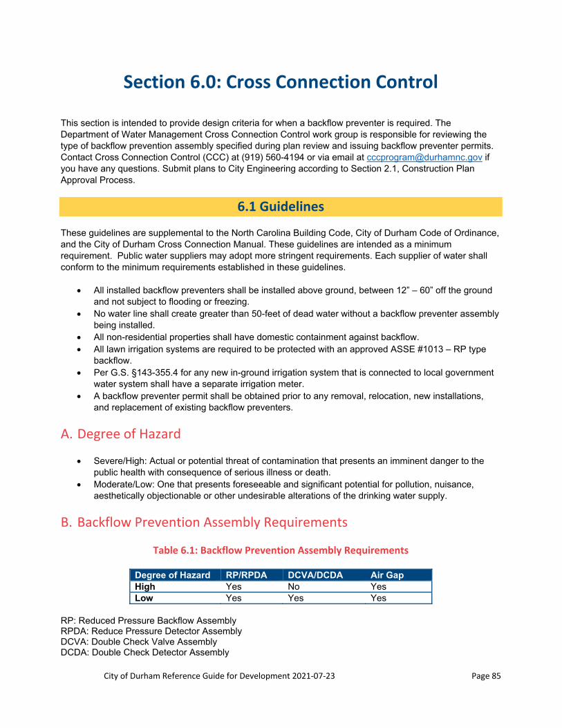
City of Durham Reference Guide for Development 2021‐07‐23 Page 85
Section 6.0: Cross Connection Control
This section is intended to provide design criteria for when a backflow preventer is required. The Department of Water Management Cross Connection Control work group is responsible for reviewing the type of backflow prevention assembly specified during plan review and issuing backflow preventer permits. Contact Cross Connection Control (CCC) at (919) 560-4194 or via email at [email protected] if you have any questions. Submit plans to City Engineering according to Section 2.1, Construction Plan Approval Process.
6.1 Guidelines
These guidelines are supplemental to the North Carolina Building Code, City of Durham Code of Ordinance, and the City of Durham Cross Connection Manual. These guidelines are intended as a minimum requirement. Public water suppliers may adopt more stringent requirements. Each supplier of water shall conform to the minimum requirements established in these guidelines.
All installed backflow preventers shall be installed above ground, between 12” – 60” off the ground and not subject to flooding or freezing.
No water line shall create greater than 50-feet of dead water without a backflow preventer assembly being installed.
All non-residential properties shall have domestic containment against backflow. All lawn irrigation systems are required to be protected with an approved ASSE #1013 – RP type
backflow. Per G.S. §143-355.4 for any new in-ground irrigation system that is connected to local government
water system shall have a separate irrigation meter. A backflow preventer permit shall be obtained prior to any removal, relocation, new installations,
and replacement of existing backflow preventers.
A. Degree of Hazard
Severe/High: Actual or potential threat of contamination that presents an imminent danger to the public health with consequence of serious illness or death.
Moderate/Low: One that presents foreseeable and significant potential for pollution, nuisance, aesthetically objectionable or other undesirable alterations of the drinking water supply.
B. Backflow Prevention Assembly Requirements
Table 6.1: Backflow Prevention Assembly Requirements
Degree of Hazard RP/RPDA DCVA/DCDA Air Gap High Yes No Yes Low Yes Yes Yes
RP: Reduced Pressure Backflow Assembly RPDA: Reduce Pressure Detector Assembly DCVA: Double Check Valve Assembly DCDA: Double Check Detector Assembly

City of Durham Reference Guide for Development 2021‐07‐23 Page 86
C. Guidelines for Backflow Assembly Installation in Water Distribution
System
RP/RPDA shall be installed above ground and shall have 12-inches minimum clearance in hotbox from the floor to the lowest point of the backflow and 6-inches minimum from walls. Support stands shall be located where they do not obstruct maintenance of the assembly.
DCVA/DCDA shall be installed above ground. All backflow preventers shall be installed per ASSE specifications listed in the seal authorization
booklet provided at http://www.asse-plumbing.org/listings.html. RPDA/ DCDA servicing fire protection, by-pass meters must read in cubic feet. No new installations shall be installed below grade, in a basement, or in a vault.
6.2 Facilities that Require Installation of a Backflow Preventer
This is not intended to be an exhaustive list. Please contact CCC if your service is not provided below to confirm adequate protection:
A. Low Hazard – DCVA or DCDA
Fire sprinkler systems without booster pump facilities, fire department connection, or chemical additives on facilities less than 5 stories
Connection to tanks, lines and vessels that handle non-toxic substances Commercial establishments Automotive service stations, bakeries and beauty shops with no health hazard and bottling plants
with no backpressure
B. High Hazard – RPZ, RPDA or air gap
Lawn sprinkler systems Wastewater treatment plants Connection to an unapproved water system or unapproved auxiliary water supply Connection to tanks, pumps, lines, steam boilers and vessels that handle sewage, lethal
substances, toxic or radioactive substances Fire sprinkler systems with booster pump facilities, fire department connection, or chemical additives
or installation for buildings with five or more stories above ground level Domestic water services for buildings with five or more stories above ground level Hospitals and other medical facilities Morgues, mortuaries and autopsy facilities Metal plating facilities Bottling plants (subject to back pressure) Canneries Battery manufacturers Exterminators and lawn care companies Chemical processing plants Dairies Film laboratories Car wash facilities Dye works

City of Durham Reference Guide for Development 2021‐07‐23 Page 87
Laundries Swimming pools Water front facilities Restaurants
6.3 Approved Backflow Prevention Assemblies
Meets ASSE standard (http://www.asse-plumbing.org/listings.html) and/or carries ASSE seal or is on the University of Southern California approval list.
6.4 Backflow Prevention Assembly Installation
Backflow prevention assemblies must be located in a place where it is readily accessible for regular testing, maintenance and inspection. Bypass lines parallel to a backflow prevention assembly shall have an approved backflow prevention assembly installed that is equal to that on the main line.
All backflow preventers shall be installed a minimum of 12-inches minimum clearance from the ground to the lowest point on the backflow assembly and no higher than 60” to the top of the assembly and 6-inches minimum from walls.
6.5 Fire Hydrants
Fire Hydrants (FH) shall be installed within 50’ of the main. If the 50’ rule cannot be met, to protect against stagnant water, then backflow protection is required. If FH cannot be re-located indicate type, size, and location on drawings of fire hydrant backflow, which shall have a Reduced Pressure Detector Assembly (RPDA) ASSE #1047, with bypass meter reading in Cubic Feet. In ASSE #1060 heated insulated enclosure, within 50’ of the domestic tee.
6.6 Lawn Irrigation
All lawn irrigation systems are required to be protected with an approved ASSE#1013-RP type backflow. Per G.S. § 143-355.4, any new, in ground irrigation system that is connected to a local government water system shall have a separate irrigation meter.
All hose bibb irrigation systems are illegal and are subject to penalty. For additional information please click here.
6.7 MEP Drawings
Effective 11/01/2017, CCC will implement a $150.00 fee to perform plan review and re-review(s) associated with received building permit applications to the City/County Inspections Department. Application fees are due once the building permit has been submitted to the City/County Inspections Department for review. In order to request CCC to perform a plan review, a CCC Plan Review Request Form must be completed. For additional information, please visit http://durhamnc.gov/952/Cross-Connection-Control.
6.8 Fee Schedule
The fee schedule can be found in our website http://durhamnc.gov/952/Cross-Connection-Control.

City of Durham Reference Guide for Development 2021‐07‐23 Page 88
Section 7.0: Sanitary Sewer System
7.1 General
This section provides minimum guidelines for the design of sanitary sewer main extensions for the City of Durham sanitary sewer collection system. The Developer/Engineer shall satisfy the requirements contained herein. See also Section 2 and 3, and the City of Durham Water and Sanitary Sewer Construction Details and Specifications.
7.2 Sizing of Sanitary Sewer Mains
A. Pipe Diameter
1. The size of the sanitary sewer lines is determined by:
NCDENR sizing requirements for sanitary sewer collection systems Future growth beyond the site Water Management and Engineering Division
2. Standard pipe diameter for public lines are 8-inch, 10-inch, 12-inch, 15-inch, 18-inch, 21-inch, 24-inch, 30-inch and 36-inch (refer to the Water and Sanitary Sewer Specifications).
3. A private sanitary sewer main shall be no less than 6-inches in diameter. The Engineer designing the sanitary sewer main shall sizing provide calculations (sealed and signed).
4. A sanitary sewer main is a collection system of 2 or more laterals, or as defined by the definition in Section 2.4. A sanitary sewer permit is required for all sanitary sewer mains, and as defined by Title 15A of the North Carolina Administrative Code, Subchapter 2H.
B. Slope Requirements
Minimum slope requirements for all pipe sizes are achieved by maintaining a minimum velocity of 2.5 ft/s through the pipe when flowing half full. The minimum slope of any particular sanitary sewer main will also govern the capacity of this pipe. Maximum slopes on sanitary sewer mains are 10%. The Engineering Division will require specific slopes as needed to insure future service and maintenance needs. Minimum slope requirements are:
Table 7.1: Minimum Slope Requirements for Sewer Pipes
Diameter of Pipe Minimum Slope 6-inch 1.00% 8-inch 0.50% 10-inch 0.28% 12-inch 0.22% 15-inch 0.15% 18-inch 0.12% 21-inch 0.10% 24-inch 0.08%
City of Durham Reference Guide for Development 2021‐07‐23 Page 89
C. Sanitary Sewer Line Material
1. Standard sanitary sewer line material is to be PVC (schedule 35 for sanitary sewer mains and outfalls and schedule 40 for 4-inch and 6-inch sanitary sewer laterals) or ductile iron class 350 pressure (refer to the Water and Sanitary Sewer Specifications). All ductile iron pipe installed within a right-of-way (ROW) or utility easement that is currently or may reasonably become public shall be lined with Protecto 401 or approved equal. Liners shall be applied per manufacturer’s requirements and must meet all ASTM requirements. The ceramic epoxy liner cannot be field applied.
2. All sanitary sewer mains located in casing pipes shall be DIP. 3. Transition of materials shall be done at manholes or with a rigid ductile iron coupling. The coupling shall
have deep socket push joint gasketed bells and a tapered flow way for a smooth transition between different pipe materials. The coupling must also be air test rated and be able to pass a mandrel for pipe inspection. Gasket grooves shall be machined and the gaskets shall be SBR rubber. The body of the coupling must meet ASTM A536 for ductile iron. The SBR rubber gaskets must meet ASTM F477.
7.3 Sanitary Sewer Line Location
A. Depth
1. Sanitary sewer mains shall be designed meeting minimum depth requirements for both sanitary sewer outfalls and street mains. Sanitary sewer outfalls shall maintain a minimum depth of 4-feet from the ground elevation to the pipe crown. Sanitary sewer mains in the street require a minimum depth of 5-feet from the ground profile to the pipe crown. If a minimum depth of 3-feet cannot be met, ductile iron pipe instead of PVC sanitary sewer pipe will be required. Sewer lines with less than 3’ of cover are not eligible for recommendation for City acceptance without a Reference Guide for Development Alternative Design approved by the Department of Water Management. This requirement does not apply to City funded projects.
2. Sanitary Sewer lines greater than 18-feet deep shall be ductile iron, have a minimum of 5-foot diameter manholes and the City will require parallel and/or oversized sewer lines with wider easements.
3. Pipe tops are to be kept 2-feet below streambed flow line elevations to avoid aerial stream crossings. The pipe shall be placed to center the crossing at the midpoint between joints of the pipe (keeping the joints as far from the creek as possible).
B. Location
Sanitary sewer lines shall be typically installed:
Under pavement within the right-of-way On the south and west sides of streets In the center of the driving lane of the street Terminate all sanitary sewer mains with manholes 18-inch below or 10-feet horizontal from water lines. If unable to maintain either of these
separations or sanitary sewer crosses over water both lines shall be made of ductile iron for a minimum of 10-feet to either side of crossing with midpoint of pipe being centered at the point of intersection.
With 18-inch separation from storm drainage lines Sewer lines that are eligible for recommendation for acceptance for ownership by the City of
Durham include all sewer mains located within City of Durham streets rights-of-way or North Carolina DOT right-of-way. Sewer lines located in private streets, public or private access common

City of Durham Reference Guide for Development 2021‐07‐23 Page 90
areas, public alleys or private alleys shall not be eligible for acceptance by the City of Durham without a Reference Guide for Development Alternative Design approved by the Department of Water Management. The alternative design request would be processed as a Tier 1 request and approval must be complete prior to approval of the associated site plan. Sewer lines that serve as outfalls to serve adjacent properties may be eligible for recommendation for acceptance by the City of Durham upon approval of a formal alternative design request received in writing from the Department of Water Management, but must be located in permanent public sanitary sewer easements. The Department of Water Management will not recommend acceptance of sewer lines in private streets or common areas that serve, or are able to serve only parcels included within the subject development. Outfalls that transition from City or DOT streets to private streets/access areas must be approved as a Tier 1 alternative design prior to approval of the subject site plan. Under all scenarios referenced above, all sanitary sewer mains shall be located within a street right-of-way or permanent sanitary sewer main easement to allow city personnel access to the main for maintenance and repair. Approval of the sanitary sewer main extension shall be contingent upon the procurement of all necessary easements. This requirement does not apply to projects funded with City funds.
Bypass pumping greater than 500’ of sewer main shall be prohibited unless approved as a Reference Guide for Development Alternative Design approved by the Department of Water Management. Bypass pumping greater than 500’ in length must be identified on the site plan and approval of the alternative design must take place prior to the site plan approval of the subject project. This requirement does not apply to projects funded with City funds.
C. Easements
1. Public sanitary sewer easements shall be a minimum of 30-feet wide. A 40-feet wide easement shall be required between 15 to 20 feet of depth. A 50-feet wide easement shall be required for sewer between 20 to 25 feet in depth.
2. All public sanitary sewer easements shall be located in open space. 3. Private sanitary sewer main easements shall be no less than 30-feet and may be greater depending
upon the depth and location. 4. Private sanitary sewer service easements shall be no less than 15-feet. 5. All sanitary sewer easements shall be drivable: Max longitudinal slope = 5:1 (H:V); Max cross slope =
10:1 (H:V). 6. No landscaping is allowed in existing or proposed sanitary sewer easements. 7. Earthwork may be allowed with City of Durham approval. Typical submittal shall be a plan and profile
provided at the site plan stage. All earthwork must be completed before sanitary sewer is installed. 8. No sediment traps, including temporary, shall be located in sanitary sewer easement or around
manholes. 9. Where required a storm drainage pipe shall be installed across the sanitary sewer easement. The size
of the pipe shall be determined using the 2-year storm event when it does not create a flooding problem. The City of Durham reserves the option to require an additional analysis based on a larger storm event and subsequent increase in storm pipe size.
D. Building Setbacks
1. Building setbacks shall be a minimum of 5-feet from all sanitary sewer easements where the depth to invert is less than 15-feet. If depth to invert is greater than 15-feet the building setback shall be a minimum of 10-feet.
2. Where no defined easement or right of way exists, the minimum building setback on all sanitary sewer pipes shall be 15 feet or 5 feet from the edge of the foundation’s loading plane to the pipe, whichever is greater.

City of Durham Reference Guide for Development 2021‐07‐23 Page 91
E. Encasements
Encasements for mains are required for crossing NCDOT roads/streets and may be required for crossing City of Durham roads/streets. Refer to the City of Durham Water and Sewer Construction Specifications for pipe encasement details. See the table in Section 5.0, Water Supply/Distribution, for encasement sizes. NCDOT and the railroads may have more stringent requirements. The pipe is required to have restrained joints under the road area. The jack & bore pit size shall be shown and labeled on the construction plans.
F. Construction
Contact Durham Engineering Inspections for a pre-construction conference no less than 48 hours before starting construction.
All sanitary sewer pipes are to be visually inspected by the Public Works Engineering Inspectors before backfilling. PVC lines shall be tested by a mandrel pull. Video inspection of sanitary sewer is required and the video submitted to Engineering Development Review (see Section 4.1).
7.4 Manholes
A. Locations
1. Manholes shall be used when sanitary sewer lines change slope or direction. 2. Manholes shall be used when sanitary sewer lines 6-inch and greater intersect. 3. Manholes shall be spaced no greater than 400-feet apart.
B. Invert and Rim Elevations
1. The maximum separation of invert in to invert out within a manhole is 0.50-feet. 2. The minimum separation of invert in to invert out within a manhole is 0.10-feet. 3. Rim elevations along outfalls are to be a minimum of 3-feet above existing ground elevation. If 4 feet or
higher, the City of Durham Engineering Division shall require flat manholes, exterior steps and safety bars on top of manhole.
4. In flood plain areas, the 100-year flood elevation shall be noted on the drawings and the rim elevations are to be set at 2-feet above the 100-year flood elevation.
5. Along outfalls, sealed top manholes with vents can be utilized if higher than 8 feet above the ground.
C. Drop Connections
1. Drops connections shall be outside drops (City of Durham Standards) unless approved by the City of Durham Engineering Division. The entire drop and upstream pipe shall be ductile iron.
2. Drop connections are required when the difference between invert in and invert out is greater than 0.5-feet (refer to Engineering Water and Sanitary Sewer specifications).
3. The minimum difference between the upper and lower inverts of the drop is 2.50-feet for 8-inch diameter sanitary sewers. Lines larger than 8-inch will require more height. The drop connections should be labeled on profile view.

City of Durham Reference Guide for Development 2021‐07‐23 Page 92
D. Manhole Diameter
1. Sanitary sewer mains from 8-inches up to but not including 18-inches in diameter require manholes to be 4-feet in diameter. Sanitary sewer mains that are 18-inches in diameter and greater will require a manhole diameter of 6 feet.
2. When the depth of the manhole exceeds 18-feet (measured from the rim to invert of the manhole) the manhole shall be a minimum 5-foot diameter.
3. Depending on the number of lines entering the manhole and the angle of the lines entering the manhole, a larger diameter will be required per Manufacturer’s specifications.
7.5 Sewer Taps
1. 4-inch lines should tap sewer mains instead of manholes where possible (exception would be cul-de-sacs, which must be tapped at the invert of the manhole).
2. 6-inch taps and larger will require a manhole at the sanitary sewer main. 3. Terminal manholes in cul-de-sacs are limited to a total number of 5, 4-inch diameter lateral services. 4. New taps into manholes shall be core drilled and installed with a flexible rubber boot.
7.6 Anchors
1. For sanitary sewer mains less than 20% slope, there are no anchoring requirements. 2. For sanitary sewer mains greater than 20% and less than 35% slope, anchors will be required a
maximum of 36-feet apart. 3. For sanitary sewer main slopes of 35% to 50%, anchors will be necessary at a maximum of 24-feet
apart. 4. For sanitary sewer mains with slopes greater than 50%, anchors will be required at a maximum of 16-
feet apart.
7.7 Creek Crossings (Aerial)
Sewer lines with less than 3’ of cover, including sewer lines that are part of aerial crossings over streams, wetlands or other hydrologic features, are not eligible for recommendation for City acceptance without a Reference Guide for Development Alternative Design approved by the Department of Water Management. New gravity sewer lines and lift stations must also be installed at a depth to eliminate the need for aerial crossings by future, adjacent development. The established standards for aerial crossings in the Reference Guide for Development does not imply that a variance will be granted for aerial crossings. Sewer aerials in floodplains or flood ways shall not be recommended for acceptance for maintenance by the City of Durham without an approved Reference Guide for Development Alternative Design request as well as all required FEMA floodplain encroachment approvals. The proposed aerial must be identified in a proposed site plan and approval of the Reference Guide for Development Alternative Design must take place prior to approval of the subject site plan. This requirement does not apply to City funded projects.
Ductile iron lock-joint pipe will be required for all creek/river/aerial crossings. Concrete supports and/or piers will also be required. All aerial crossings require the pipe or casing pipe to be at least 1-foot above the 10-year flow depth and at least above the 25-year flow depth.

City of Durham Reference Guide for Development 2021‐07‐23 Page 93
7.8 Services
Sanitary sewer services shall be installed according to the City of Durham standards and specifications. Standard requirements are:
1. Sewer services shall not cross property lines. 2. Cleanouts every 75-feet maximum. 3. New single family homes, duplexes or triplexes that are proposed with City sewer service that do not
also receive City water service shall install a plug valve on the sewer service at the ROW line. A cleanout must be provided between the customer and the plug valve at the ROW line. These plug valves shall be installed by the developer with no City participation in the cost and must be present prior to a COC being granted for the property. The plug valve shall be installed in accordance with the detail provided by the City
4. 'Y' Cleanouts shall be installed at the right-of-way line or at the sewer easement line. Use of combinations are not permitted.
5. Whenever possible, laterals shall be perpendicular from the sanitary sewer main to the clean out at the right-of-way or the sanitary sewer easement.
6. When cleanouts are necessary in traffic areas, they shall be built according to the City of Durham details.
7. Cleanouts that are not traffic bearing are to be flush with the ground with an 18-inch by 18-inch by 4-inch concrete (3000-pounds per square inch (psi) min.) protective collar.
8. Cleanouts are to be installed according to the City of Durham details. 9. Laterals to be installed at the following minimum grade:
Minimum grade for a 4-inch diameter lateral is 2% Minimum grade for a 6-inch diameter lateral is 1%
10. Pool drain shall be tied into sanitary sewer. Discharge into pool drain must be by pumping, not gravity. 11. Carwash drain shall be tied into sanitary sewer. The drain shall be placed such that it will not collect
rainwater and should be located under a roof, with the area beyond the roof sloping away from the drain. The drain line shall contain a grit separator and oil/water separator.
12. Dumpster pads for food service establishments and all establishments utilizing a compactor shall have a drain connected to the sanitary sewer. The areas beyond the dumpster/trash compactor pad shall be sloped to drain away from inlet.
13. All force mains that are covered under the plumbing code shall discharge by gravity into public lines starting at the right-of-way line.
14. Sanitary sewer connections to stubbed out services shall not be made until As-built drawings are approved.
7.9 Force Mains
1. All public sanitary sewer force mains shall be ductile iron and be sized the largest diameter capable of maintaining 2.5ft/s of velocity at lift station startup. Manifolding proposed force mains on to existing force mains is not permitted. Bends are not allowed in force mains. Plan and profile drawings are required. See the Section 2.1, Construction Plan Approval Process.
2. For private force mains, the Engineer shall submit designs to City of Durham Engineering Division (see Section 2.1, Construction Plan Approval Process) and shall also conform to requirements of the State of North Carolina. The private force main shall connect to a standard gravity service cleanout at the right-of-way or easement line.
City of Durham Reference Guide for Development 2021‐07‐23 Page 94
3. All ductile iron pipe used for force mains shall be lined with Protecto 401, or equivalent (approval by Engineering Division required), to reduce corrosive action. This is only required where the water column separates from the pipe and creates an air pocket (at high points with air release valves).
4. Manifolded sanitary sewer force main connections to existing or proposed sanitary sewer force mains are prohibited.
7.10 Pump Stations
1. For projects involving a sanitary sewer pump station, the applicant shall contact the Water Management Department and City Engineering Division prior to submittal of site plan or construction plans. This is to determine if the station is required or if there is a gravity option, whether or not the station will be public or private and to determine the designs that apply. The Water Management Department shall decide on types of equipment, station layout and pump operation characteristics.
2. The Lift Station Design Standards from Water management can be found here: https://durhamnc.gov/DocumentCenter/View/26106/. The Water Management Department will review and approve the pump station design construction documents.
3. Driveways into the pump station access drives shall have a minimum radius of 25 feet. 4. City Engineering Division will hold the approval of the construction drawings of a project until the Water
Management Department has approved the pump station design.
7.11 Sanitary Sewer Abandonment
A. Sanitary Sewer Main and Manholes
Abandonment of manholes shall consist of removal of manhole structures to 3-feet below finished grade, filling the manhole with concrete to an elevation of 1-foot above the crown of the pipe and filling the remaining portion with stone. The area of this removal shall be backfilled with clay and compacted well.
When sanitary sewer mains are abandoned, 5-lineal feet of sanitary sewer nearest the sanitary sewer to remain live shall be filled with concrete.
B. Services
Abandonment of sanitary sewer service lines shall consist of excavating down to the service connection to the main, cutting this connection and installing a watertight plug in the main. The service line and all clean-out risers on the service line shall be removed. Utility Service Abandonments will take place prior to beginning utility construction work for a project. Any excavation as part of abandoning utilities will require backfilling per City of Durham standards.

City of Durham Reference Guide for Development 2021‐07‐23 Page 95
Section 8.0: Stormwater Conveyance Systems
This section provides design criteria for stormwater design of storm drainage conveyance systems. All designs should be submitted for review as per Section 2.0. See Sections 8.1 to 8.4 for the requirements of the Stormwater Impact Analysis, the design criteria of stormwater control measures, and as-built requirements.
8.0.1 Land Disturbance
A. Grading Permits
Obtain grading permits covering erosion and sediment (E&S) control measures from the Durham County Soil and Erosion Control Division (S&E) after site plan approval. The permit must be obtained before starting any grading and construction work.
B. Other Permits
Other proposed environmental impacts, such as piping a stream, may require permits from:
United States Army Corps of Engineers North Carolina Department of Environmental Quality Durham City/County Planning Department City of Durham Public Works Engineering and Stormwater Services Divisions
C. Erosion Control
The Erosion and Sediment Control plan sheets shall be separate from the stormwater and grading plan sheets. Include the E&S Control Plan in the construction drawings. Even though the City doesn’t approve this plan, the plan shall be included in the construction drawings. Any structures and/or pipes shown in the E&S plan that are proposed to be permanent in a project shall not be installed prior to approval of the construction plans and the payment of the inspection fees.
8.0.2 Design Criteria
A. Stormwater Conveyance Systems Design
Stormwater conveyance systems (storm drain systems, culverts and ditches/open channels) shall be sized based upon criteria listed in Table 8.0.1.
Table 8.0.1: Design Criteria for Installation of New Stormwater Conveyance Systems
System Drainage Basin Size
Design Storm
Design Criteria
Culverts < 100 acres 10-year HW/D must be less than or equal to 1.0 for both inlet
and outlet control conditions.

City of Durham Reference Guide for Development 2021‐07‐23 Page 96
≥ 100 acres 25-year HW/D must be less than or equal to 1.0 for both inlet and outlet control conditions.
Storm Drains
< 100 acres 10-year HGL for the entire system is to be below crown of all pipes
≥ 100 acres 25-year HGL for the entire system is to be below crown of all pipes
Open Channels
< 100 acres 10-year 10-year storm event must be contained within channel banks with non-erosive velocities or suitable channel lining.
≥ 100 acres 25-year 25-year storm event must be contained within channel banks with non-erosive velocities or suitable channel lining.
B. Existing Conveyance Systems
If properties proposed for development/re-development contain existing through-drainage systems (Systems) (i.e. pipe system, open channels, etc.), the Systems shall be evaluated with the criteria in Table 8.0.1. If the existing Systems do not comply with the criteria, the existing Systems shall be replaced or supplemented to meet the criteria.
If any existing System is replaced or supplemented or if any new System is proposed to meet the criteria outlined in Table 8.0.1 or any other local, State or Federal requirement, a stormwater impact analysis (SIA) shall be prepared in accordance with Section 8.1. Any increase in flow on downstream properties may require on-site peak discharge rate attenuation or off-site improvements.
C. No Flooding of Buildings
All stormwater conveyance systems shall be designed so that no building or habitable structure, either proposed or existing, is flooded or have water impounded against it during the 100-year storm event.
D. Overland Relief
Overland relief shall be provided for all stormwater pipe systems, inlets, and culverts such that no building or habitable structure will be flooded or have water impounded against it during the 100-year storm event (see figure below). 100-year storm ponding elevations, areas and overland relief zones shall be shown and labeled on the Construction Drawings. A separate grading and drainage plan sheet shall be dedicated to delineating these zones. Use a 100% clogging factor on the structures when calculating the 100-year ponding elevation.

City of Durham Reference Guide for Development 2021‐07‐23 Page 97
Figure 8.0.1: 100‐year Overland Relief Exhibit
E. Through‐drainage Systems
Conveyance systems, such as culverts and through-drainage storm systems, shall be designed to pass the 25-year storm for residential streets and 50-year storm for collectors without encroaching upon the City’s roadway pavement.
F. Maximum Discharge into the Right of Way
The maximum runoff allowed to sheet flow into the right of way is 1-cfs during the 10-yr storm before requiring a structure to collect the runoff.
Building
FFE = 300
299
299
300
298
297
A
A
100-yr Storm Elevation
Cross section A-A
(NTS)
Grading Plan (NTS)
Continues to outfall

City of Durham Reference Guide for Development 2021‐07‐23 Page 98
8.0.3 Storm Drainage
A. Hydraulic Grade Line Calculations
Hydraulic grade line (HGL) calculations shall take into account all head losses, friction factors and bypass flows.
The starting point of downstream hydraulic gradient at the outlet end of the storm drain system shall be determined by the following criteria:
If the receiving body of water is a detention basin or lake, the controlling water surface elevation shall either be the normal high water elevation in the lake or the high water elevation in the detention basin for the same design storm as that of the storm drain or shall begin at the downstream crown of the outlet of the storm drain system, whichever is greater.
If the outfall is a stream or open channel, the controlling water surface elevation (as computed from backwater calculations starting at a downstream channel cross-section where the channel constricts) shall be the water surface elevation in the channel for the same design storm as that of the storm drain or shall begin at the downstream crown of the outlet of the storm drain system, whichever is greater.
If the outfall is another storm drain, the controlling elevation shall be the hydraulic grade line elevation of the receiving storm drain immediately downstream of the junction for the same design storm or shall begin at the downstream crown of the outlet of the storm drain system, whichever is greater.
The HGL shall not exceed the top of structures or gutter elevations for the 25-year storm event for any storm sewer system.
In instances where the City decides to allow the 10-year HGL to exceed the crown of the pipe, all out of compliant pipe segments from one structure to another structure shall be constructed with water tight joints rated to 10-psi. In addition, the pipe shall be manufactured without lift-holes if applicable.
B. Hydraulic Grade Line Report
Both 10-year and 25-year HGL calculations shall be provided with the Construction Drawing submittal for all proposed storm conveyance systems as a separate report or in the Construction Drawings. Include in the report:
Intensity (I) Time of concentration (Tc) Runoff coefficient (C) Runoff coefficient correction factor for 25-yr HGL analysis (C25yr = C10yr x 1.1) Drainage area map Profiles showing the HGL in the pipes

City of Durham Reference Guide for Development 2021‐07‐23 Page 99
8.0.4 Culverts
A. Hydraulic Grade Line Report
Both inlet and outlet control calculations for all proposed culverts shall be provided with the Construction Drawing submittal. These calculations must demonstrate that the headwater depth ratio (HW/D) is ≤ 1.
For outlet control, the downstream hydraulic gradient at the outlet end of the culvert shall begin at a “known” water surface elevation or at the downstream crown of the culvert, whichever is greater. The “known” water elevation is computed from backwater calculations starting at a downstream channel cross-section where the channel constricts.
B. Headwalls
Concrete end-sections or concrete (poured-in place) headwalls and endwalls shall be required when:
Pipes ≥ 36 inch in diameter Pipes < 36 inches if HW/D is > 0.90 if there is a tailwater condition at the pipe outlet such that the crown is submerged smaller sized pipes will require headwalls if within a steep slope, per Engineering
For stormwater ponds headwalls and endwalls see Section 8.3.
Provide a concrete curtain with all proposed flared end-sections. The curtain wall shall extend for the entire width of the flared end-section opening, shall be at least 4 inches thick and shall extend to a depth of 18 inches deep or below the bottom of adjacent riprap, whichever is deeper. The curtain wall shall be constructed with a concrete strength of at least 3000 psi.
Provide riprap or approved alternative outlet protection calculations for all stormwater outlets with the Construction Drawing submittal.
HDPE flared-end-sections are not allowed.
For public streets crossed with an open-ended pipe ≤ 24 inches in diameter, a 4-foot high PVC coated dark green chain link fence will be required at the right-of-way for a length measured from the culvert to the end of the fill section.
8.0.5 Open Channels
Open channel conveyance systems shall be sized for the 10-year storm event (drainage basin < 100 acres) or 25-year event (drainage basin ≥ 100 acres). The design storm shall be contained within the channel banks with non-erosive velocities for the channel lining. Design calculations for all channelized stormwater flow shall be provided with the Construction Drawing submittal. A table of the channel segment, slope, channel area, (calculated) velocity, channel lining, and maximum channel lining velocity shall be provided on the construction plans. Manufacturer information may be required to support maximum channel velocity.
A yard swale will be considered a through drainage channel if and when it drains two or more upstream properties or conveys a 10-year storm event peak flow rate of ≥ 2 cfs. A stormwater easement shall be provided for the yard swale.

City of Durham Reference Guide for Development 2021‐07‐23 Page 100
When drainage ditches cross sanitary sewer easements, storm drain pipes are to be installed. The pipes are to be sized to accommodate the 2-year storm event flow of the ditch. The pipe shall cross perpendicular to the easement and shall extend the entire width of the easement.
The Tractive Force method shall be used to determine the appropriate channel lining to mitigate erosion in the open channel for the appropriate design storm listed in Table 8.0.1 above. The Maximum Permissive Velocity method is not acceptable to determine the appropriate channel lining.
8.0.6 Gutter Spread
A. Allowable Spread
Gutter spread calculations shall be provided for all proposed public and private streets with the Construction Drawing submittal. Adequate drainage controls shall be provided so that the gutter spread does not exceed half the travel lane width for the 2-year storm event. The bypass into an intersection shall be ≤ 0.10 cfs (cubic feet per second) for the 2-year storm event (applies to driveways as well). Curb inlets are not allowed within the radii of driveways or street intersections. They are typically provided upstream of intersections.
Half of a travel lane is calculated as ¼ of the pavement section plus the width of the gutter. For cul-de-sacs, use the road stem of the cul-de-sac for calculating the allowable gutter spread.
Table 8.0.2: Allowable Gutter Spread on Typical Back‐to‐Back Widths
B-B Width with 24 inch Curb and Gutter (feet)
Allowable Gutter Spread (feet)
B-B Width with 30 inch Curb and Gutter (feet)
Allowable Gutter Spread (feet)
22 6.0 23 6.5 24 6.5 25 7.0 26 7.0 27 7.5 32 8.5 33 9.0
B. Calculations
Gutter spread calculations shall include the following:
All flow rates in cfs to the nearest hundredth All bypasses and the inlet that it will be directed to. Use a 50% clogging factor to determine the inlet capacity for sump conditions Methodology and equations used to determine the spread Table of checks for spread and bypass:
Table 8.0.3: Checks for Spread Calculations
Inlet # Bypass Inlet Spread (feet) Allowable Gutter Spread
(feet)
Bypass (cfs)
Check
CB1 CB2 4.0 6.0 0.00 Pass CB2 Offsite 5.5 6.0 0.05 Pass

City of Durham Reference Guide for Development 2021‐07‐23 Page 101
8.0.7 Stormwater Conveyance Materials and Installation Standards
A. Diameter
The minimum pipe diameter for culverts and storm sewer systems shall be 15 inches.
Connection to downstream smaller diameter pipes will not be allowed.
B. Slope
Pipe systems and culverts shall be at a 1% minimum slope. Slopes of 0.7% or higher may be allowed if a cleansing or scour velocity of 2.5 ft/s is maintained in the pipe during a 3 in/hr storm. Provide these calculations with the Construction Drawing submittal for approval.
All changes in slope in storm drainage systems shall occur at a structure.
Open channels shall have a minimum slope of 2%.
C. Pipe Material
The City of Durham allows the following pipe materials:
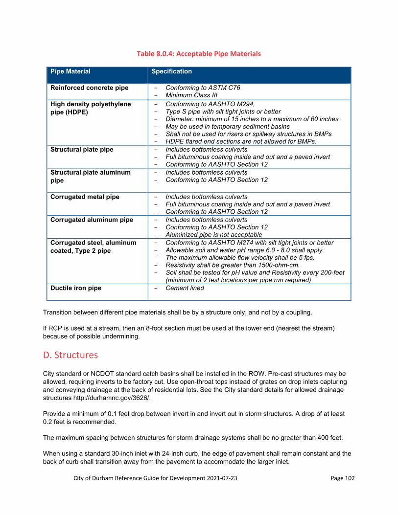
City of Durham Reference Guide for Development 2021‐07‐23 Page 102
Table 8.0.4: Acceptable Pipe Materials
Pipe Material Specification
Reinforced concrete pipe - Conforming to ASTM C76 - Minimum Class III
High density polyethylene pipe (HDPE)
- Conforming to AASHTO M294, - Type S pipe with silt tight joints or better - Diameter: minimum of 15 inches to a maximum of 60 inches - May be used in temporary sediment basins - Shall not be used for risers or spillway structures in BMPs - HDPE flared end sections are not allowed for BMPs.
Structural plate pipe - Includes bottomless culverts - Full bituminous coating inside and out and a paved invert - Conforming to AASHTO Section 12
Structural plate aluminum pipe
- Includes bottomless culverts - Conforming to AASHTO Section 12
Corrugated metal pipe - Includes bottomless culverts - Full bituminous coating inside and out and a paved invert - Conforming to AASHTO Section 12
Corrugated aluminum pipe - Includes bottomless culverts - Conforming to AASHTO Section 12 - Aluminized pipe is not acceptable
Corrugated steel, aluminum coated, Type 2 pipe
- Conforming to AASHTO M274 with silt tight joints or better - Allowable soil and water pH range 6.0 - 8.0 shall apply. - The maximum allowable flow velocity shall be 5 fps. - Resistivity shall be greater than 1500-ohm-cm. - Soil shall be tested for pH value and Resistivity every 200-feet
(minimum of 2 test locations per pipe run required) Ductile iron pipe - Cement lined
Transition between different pipe materials shall be by a structure only, and not by a coupling.
If RCP is used at a stream, then an 8-foot section must be used at the lower end (nearest the stream) because of possible undermining.
D. Structures
City standard or NCDOT standard catch basins shall be installed in the ROW. Pre-cast structures may be allowed, requiring inverts to be factory cut. Use open-throat tops instead of grates on drop inlets capturing and conveying drainage at the back of residential lots. See the City standard details for allowed drainage structures http://durhamnc.gov/3626/.
Provide a minimum of 0.1 feet drop between invert in and invert out in storm structures. A drop of at least 0.2 feet is recommended.
The maximum spacing between structures for storm drainage systems shall be no greater than 400 feet.
When using a standard 30-inch inlet with 24-inch curb, the edge of pavement shall remain constant and the back of curb shall transition away from the pavement to accommodate the larger inlet.

City of Durham Reference Guide for Development 2021‐07‐23 Page 103
1. Yard Inlets
A standard structure shall be used instead of a small plastic yard inlet (nyloplast, for example) when the drainage area is larger than 400sf.
E. Depth
Stormwater pipes shall have a minimum cover (from the top of the pipe to the finished grade) of 12 inches within private property and a minimum cover of 18 inches within the ROW. Pipes 30 inches in diameter or larger shall be deep enough to accommodate drainage structures. Pipes 60 inches in diameter or larger shall have a minimum of 24 inches of cover. When pipe is exposed to construction loads or other loads in excess of AASHTO H-20, an additional 12 inches of cover shall be provided.
Stormwater pipes excessively deep (depth > 20 feet) require special approval from the Engineering Development Review Group.
Vertical distance required:
12 inches of separation from waterlines (if < 12 inches, provide concrete collar at crossing) 18 inches of separation from sanitary sewer (if < 18 inches, sewer shall be DIP)
F. Horizontal Separation
Maintain a minimum of 5 feet horizontal separation between storm pipes, (measuring from the centerline of the pipe) and trees and other utilities.
G. Construction
Contact Durham Engineering Inspections for a pre-construction conference no less than 48 hours before starting construction.
All storm drain pipes are to be visually inspected by the Public Works Engineering Inspectors, with an option to require the system to be mandrel tested. Video inspection of storm drain systems is required and the video submitted to Engineering Development Review (see Section 4.1).
All pipes shall be installed per the latest NCDOT Standard Specifications for Street and Highway Construction unless stated otherwise in the City’s Reference Guide for Development, Standard Details and Specifications. Backfill material used to install pipe within the street ROW shall be as defined by latest version of NCDOT Standard Specifications for Street and Highway Construction. Upon submittal of written certification of material suitability by a licensed geotechnical engineer, NCDOT Class I material may be used. All backfill material shall be approved by the PW Engineering Inspections prior to placement of material within the street ROW.
8.0.8 Stormwater Easements and Building Setbacks
Stormwater conveyance systems for “through drainage” shall be placed in a storm drainage easement when located outside of the ROW. “Through drainage” shall be defined as the artificial collection and conveyance of drainage from one property (including the public right-of-way) through another property. It is recommended that these stormwater easements be located on open space and not within private property.

City of Durham Reference Guide for Development 2021‐07‐23 Page 104
A. Easement Width
The width of stormwater easements for pipes shall be calculated as follows: width of stormwater easement equals 14 feet plus the outer pipe diameter plus 2 feet for every 1 foot of vertical depth greater than 5 feet. The depth shall be measured from the top of the ground to the invert of the pipe.
Stormwater easements for channels are to be calculated as follows: width of stormwater easement equals to the channel width measured from the top of bank plus 7 feet from the top of bank on each side of the channel.
All stormwater easements shall be drivable:
Max longitudinal slope: 5:1 (H:V) Max cross slope: 10:1 (H:V)
B. Building Setback
1. Storm Drainage within Easements
The minimum building setback on all stormwater easements shall be 2 feet. Excessively deep storm sewers shall have an additional building setback from the easement:
5 feet for pipes between 10 feet and 15 feet in depth (measured from the ground surface to the pipe invert)
10 feet for pipes deeper than 15 feet
2. Storm Drainage within Private Property (when easements are not required)
The minimum building setback on all stormwater pipes shall be 7 feet or 2 feet from the edge of the foundation’s loading plane to the pipe, whichever is greater.
C. Not Allowed within Easements
Structures are not allowed within stormwater easements and easement setback. Easements and setbacks shall not intrude within proposed building envelopes.
In no instance shall the load plane of a building or structure come within 5 feet of the outside edge of a storm pipe.

City of Durham Reference Guide for Development 2021‐07‐23 Page 105
Figure 8.0.2: Easement and Easement Setback Exhibit
Retaining walls may encroach on the easement setback if the geogrid for the wall is located outside of the easement.
Large landscaping, such as trees and large shrubs, are not allowed within stormwater easements.
D. Overlapping Easements
Stormwater easements shall not be combined with other utility easements. However, stormwater easements may overlap with other utility easements as long as the utility in one easement does not encroaches into the easement of the other utility and all setbacks requirements are met.
2’ s
etba
ck
Storm Drainage Easement and Setback
(NTS)
Storm Drainage Easement 14’ minimum

City of Durham Reference Guide for Development 2021‐07‐23 Page 106
Figure 8.0.3: Overlapping Easements Exhibit
E. Blanket Easements and Variable Width Easements
Blanket easements are allowed for storm drainage crossing townhome lots when a blanket easement already exists in the townhomes for maintenance of other utilities within the lots.
Variable width easements are allowed for roof leaders and small yard drainage systems that will be maintained by the townhomes’ Home Owners Association. The maintenance of these systems is expected to be done by digging by hand so a smaller width easement is allowed.
8.0.9 Retaining Walls
Retaining walls shall be clearly labeled on the grading plan sheet of site plans and the construction drawings. Provide the top and bottom wall elevations at the ends of the wall, middle of the wall, and any spot where wall changes direction. Building permits for retaining walls shall be reviewed and approved by Engineering only after the construction drawings of the project have been approved.
Retaining walls and its geogrid are not allowed within the public ROW. Retaining walls shall be setback from the right of way a distance equal to the height of the wall.
Retaining walls shall be located outside storm drainage easements. Retaining walls may encroach into the 2 feet easement setback as long as the geogrid of the wall is located outside of the easement.
Storm drainage pipes may only cross a retaining wall at the ends of the wall.
30’ wide sanitary sewer
easement
Pipe located in the centerline of the easement
20’ wide stormwater easement
(NTS)

City of Durham Reference Guide for Development 2021‐07‐23 Page 107
Figure 8.0.4: Retaining Wall Installation adjacent to the Right of Way

City of Durham Reference Guide for Development 2021‐07‐23 Page 108
Section 8.1: Stormwater Impact Analysis
This section provides criteria for designing stormwater control measures and generating a stormwater impact analysis (SIA) including narrative, peak runoff analysis, pollutant requirements, and stormwater control measure (SCM) considerations. All site plan submittals shall meet the requirements in Section 1.0, Public Works Department Engineering and Stormwater Development Review Divisions and Department of Transportation and the Rezoning, Site Plan and Plat Process. All construction drawing and SCM design calculations shall be submitted as per Section 2.0, City of Durham Construction Drawing Review Process and Section 8.0, Stormwater Conveyance Systems through Section 8.4, SCM Design/As-Built Summary Sheets.
Prior to the approval of any preliminary plat or site plan required by the Unified Development Ordinance, the owner of the property proposed for development shall submit a SIA that complies with the requirements set forth in the Durham City Code and this Reference Guide for Development.
SIA submittals that do not meet the minimum requirements listed below in Sections 8.1.1 through 8.1.6 may be returned without review for supplementation, revisions, and resubmittal.
8.1.1 General
A. Purpose of the Stormwater Impact Analysis
All land-disturbing activities that require a preliminary plat or site plan submittal to the Planning Department must include an SIA with each site plan submittal. The SIA is intended to determine the need for SCMs, provide justification for the design of SCMs, and demonstrate how development complies with the requirements as written in the Stormwater Performance Standards for Development ordinance, which is found in Durham City Code Chapter 70, Article X, Sections 70-736 through 70-749. The purpose of these requirements is to assess, prior to development, potential flooding, erosion, and water pollution impacts on existing downstream areas as a result of a proposed development. The SIA requirements are applicable to:
All site plans deemed by the City-County Planning Department to be above a Level 1 (Level 1 is a site plan requiring only Planning Department review),
Construction drawing approval where a site plan is not required.
B. Key Definitions
Within Section 8.1, the following terms and phrases not otherwise defined by Section 70-736 of the City Code, regardless of capitalization, shall have the meanings set forth below:
Land Disturbance - a change in the natural cover or topography of land that may result in sedimentation, and includes but is not limited to grubbing, stump removal, removal of topsoil, coarse or fine grading, and disturbance to the subgrade.
New Impervious – Any impervious surface placed on previously pervious surface or where its construction triggers the land disturbance definition as of the applicable baseline date. Impervious areas that are redeveloped or replaced down to the subgrade are considered new impervious if the amount of impervious area increases over the baseline date.

City of Durham Reference Guide for Development 2021‐07‐23 Page 109
Pre-Development – The land cover lawfully established prior to the applicable baseline date. Baseline dates vary by rule as described in the City Code Chapter 70, Article X, Sections 70-736 through 70-749.
Project – Changes to a site either proposed or previously having taken place (Previous Project).
Post-Development – Changes in land cover on a site from the pre-development land cover.
Regulatory Basin – Referring to one of the three stormwater basins within the City of Durham subject to state water quality regulations, including Falls, Lower Neuse, and Jordan Basins.
Stormwater Development Review – The stormwater development plan reviewers in the City of Durham Department of Public Works.
Total Maximum Daily Load (TMDL) – A federal regulatory term describing a limitation on the amount of a specific pollutant that a surface water can receive while still meeting water quality standards.
C. Formatting
SIAs shall be signed and sealed by a registered North Carolina Professional Engineer having experience in the design and construction of SCMs similar in nature to that proposed. In accordance with 21 NCAC 56.0701(c)(4) and North Carolina Board of Engineers and Land Surveyors policy, in cases where a licensee in responsible charge of the work is unavailable to complete the work, “a successor licensee may take responsible charge by performing and documenting all professional services to include developing a design file including work or design criteria, calculations, code research, and any necessary and appropriate changes to the work… The successor licensee shall have control of and responsibility for the work product and the signed and sealed originals of all documents.”
1. Cover Sheet with Professional Engineer Seal, Signature, and Date
2. Table of Contents
3. Project Narrative
4. Stormwater Development Review Submittal Checklist (Type of checklist based on review process).
5. Reference Material (including but not limited to USGS topo, Soil Survey map1, FEMA map, stream determinations, rainfall data, etc.)
6. Peak Flow Analysis – Hydrology and Hydraulics Modeling
7. Water Quality Calculations
8. SCM and Other Design Calculations (Construction Drawing Stage Only)
9. SCM Design Summaries (Construction Drawing Stage Only)
These sections must be ordered as listed, however further section breakdown is both permitted and encouraged.
1 See Appendix A, “Procedure for Obtaining a Copy of the Published NRCS Soil Surveys for NC” for directions on how to obtain the 1976 Soil Survey map information.

City of Durham Reference Guide for Development 2021‐07‐23 Page 110
Hydrology and hydraulic calculations shall be provided in an 8.5-inch by 11-inch format (refer to checklists found in Section 1.2, Stormwater Development Review Section Rezoning, Site Plan, Preliminary Plat and Final Plat Submittal Requirements, and Section 2.0, City of Durham Construction Drawing Review Process).
Hydrologic drainage area maps shall be provided in a 24-inch by 36-inch format to a scale no less than 1 inch = 30 feet unless approved otherwise on a case by case basis. Large developments or tracts of land where a smaller scale can limit the number of sheets and break lines could be adequate justification for utilizing a scale smaller than 1 inch = 30 feet.
Pre- and post-development and SCM drainage area land use maps for the nutrient calculations must be to a scale no smaller than 1 inch = 100 feet unless a smaller scale is allowed on a case specific basis. Generally, the City discourages multiple sheets with break lines when a better alternative exists to minimize by using a smaller scale.
All SIA materials shall be bound together with each section tabbed, in a three-ring notebook. Loose paper will not be accepted.
D. Electronic Submittal
Submit to Stormwater Development Review in accordance with Development Service Center protocols. The electronic submittal shall contain copies of the following in the listed format:
Sealed SIA: The entire document including narrative, data, calculations, pre- and post-development drainage area and land use maps, and all appendices. (Format: PDF)
Site Plan (Format: PDF)
Stormwater Nutrient Accounting Tool (Format: Excel)
Nutrient Reporting Form (Format: Excel)
Construction Drawings – For Construction Drawing Review Only (Format: PDF)
SCM Design Summaries – For Construction Drawing Review Only (Format: PDF)
SCM Drainage Area Polygon - For Construction Drawing Review Only (Format: AutoCAD DWG/DXF, Microstation DGN, or ESRI Shapefile)
o Applicable only for a development where there are one or more proposed or utilized SCMs, however, any existing SCMs on site must be included as well.
o Files must be georeferenced to North Carolina State Plane (NAD83) coordinate system in the units of US Survey Feet.
o If CAD file is used, isolate the SCM drainage area polygon to a single CAD layer named: SCM_AREAPOLY. (Ancillary layers can be included but are not required).
Additional items such as soils report for seasonal high water table determination, stream determination letters/reports, etc. (Format: PDF) (Soils reports for seasonal high water table determination are required for construction drawing review, but are encouraged earlier in the review process.)
E. Previous Projects and SIAs
If a previous project was completed onsite after April 23, 1997 and required an SIA; a copy of the previously approved, sealed, and signed SIA shall be submitted with each plan submittal including re-submittals if designer desires to utilize this. Prior stormwater requirements shall continue to apply to existing
City of Durham Reference Guide for Development 2021‐07‐23 Page 111
development so long as new development does not trigger requirements that supersede those previously in effect. Redevelopment that is exempt under the currently enforced city standards shall continue to maintain and reconstruct all SCMs in compliance with approved plans.
F. Required Reference Material
The following supplemental material shall be included with each submittal regardless of the presence of streams or floodplain on the site:
A legible copy of the most recent United States Geological Survey 7.5 Minute Quadrangle map including map reference, with site boundary clearly delineated and labeled. The map shall clearly show streams.
A legible copy of the published hard copy Durham County Soil Survey map including map reference, with site boundary clearly delineated and labeled. The map shall clearly show streams. This map is for surface water identification purposes only and shall not be used for soil data. The official soil data for any county is the Web Soil Survey.
A legible copy of the Web Soil Survey Map or a geotechnical exploration report with map, clearly delineating and labeling the site boundary. The map shall show soil classification and include a reference table that describes the hydrologic soil group classification.
A legible copy of the effective Federal Emergency Management Agency National Flood Insurance Program Flood Insurance Rate Map including map number, map date, and site boundary clearly shown and labeled. The effective and/or future FEMA 100-year floodplain, with base flood elevations (if applicable), shall be shown on the plans. The copy of the Flood Insurance Rate Map can be via the actual FEMA Flood map, a FEMA Firmette, or a map export from the North Carolina FRIS website. http://fris.nc.gov/fris/Index.aspx?FIPS=063&ST=NC&user=General%20Public.
Completed Stormwater Development Review checklist for the applicable submittal type. This checklist shall be updated with each submittal.
NOAA Atlas 14 Point Precipitation Frequency Estimates with hydrographs specific to the site location. This shall be in the form of a printout of the Atlas 14 website showing the map with the site location selected. The hydrographs shall be downloaded and presented graphically.
G. Meetings
The owner, designer, or other interested party may request a meeting with Stormwater Development Review (preferably after a pre-submittal meeting has been completed) to discuss specific items pertaining to a project. When requesting a meeting, the party making the request shall include a brief agenda describing the purpose of the meeting and the items to be discussed.
It is likely that Stormwater Development Review will not make decisions pertaining to special circumstances or project complications during a meeting unless guidance is already available in City Standards. If a decision is requested, a full evaluation will be conducted within a reasonable timeframe to include information provided during the meeting and other available resources.
Stormwater Development Review reserves the right to decline a meeting request for any justified reason.
H. Designer’s Letter SIA
Any plan submittal where a full SIA is not warranted shall include a Designer’s Letter. A Designer’s Letter may be submitted in lieu of a full SIA when the applicant can demonstrate all of the following:

City of Durham Reference Guide for Development 2021‐07‐23 Page 112
Exemption from the peak runoff control requirements in Section 70-738(b) of the City Code of Ordinances,
Exemption from the stormwater pollutant standards in Section 70-739 of the City Code of Ordinances, and
Preservation of existing or previously-approved drainage patterns.
If existing or previously approved drainage patterns are proposed to be changed, if an increase in impervious area (over that currently existing or that previously approved in the SIA) is proposed, or if new floodplain has been proposed on developed property downstream, a new or revised full SIA will be required. For diminutive increases in impervious area, consultation with Stormwater Development Review is suggested.
Any plan submittal, where a full SIA is not warranted, shall include a Designer’s Letter signed and sealed by a registered professional (North Carolina Professional Engineer or North Carolina Registered Landscape Architect). The Designer’s Letter shall reference:
The name of the site,
The pin number(s) for the affected parcels,
The current permit case number,
Previous case numbers (if applicable),
The regulatory basin within which the site is located, and
The watershed protection overlay in which the site is located.
The Designer’s Letter shall also provide a brief explanation of why a full SIA (either revised or new) is not warranted and include the following attachments:
1. Completed, signed, and sealed Stormwater Development Review Site Plan Submittal Checklist. The checklist shall note when items on the list may not be applicable to the submittal by writing "n/a" on the Applicant Initials line. Stormwater Development Review will ultimately determine if items are required.
2. Copies of all previously approved signed and sealed SIAs for the site (if prepared for previous projects).
3. A legible copy of the United States Geological Survey 7.5 Minute Quadrangle map including map reference, with site boundary clearly delineated and labeled. The map shall clearly show streams.
4. A legible copy of the published Durham County Soil Survey map including map reference, with site boundary clearly delineated and labeled. The map shall clearly show streams. This map is for surface water identification purposes only and shall not be used for soil data. The official soil data for any county is the Web Soil Survey.
5. A legible copy of the effective Federal Emergency Management Agency National Flood Insurance Program Flood Insurance Rate Map including map number, map date, and site boundary clearly shown and labeled.
The letter below serves as an example for an appropriate Designer’s Letter.

City of Durham Reference Guide for Development 2021‐07‐23 Page 113
March 25, 2017
To: Stormwater Development Review
City of Durham Department of Public Works From: Your Name Here, PE Top-of-the-Heap Engineering Services, LLC 101 Faraway Street Devil’s Advocate, NC 27700 Ph: (919) 555-1212 Email: [email protected] Subject: Designer’s Letter Ref: Fastest Food Restaurant Parking Renovation Case #: D1751039 Previous Case#: D0841999 PIN: 0823-12-86-3333 Watershed: Falls Lake Water Supply Overlay: None
The subject site plan concerns a parking lot renovation that includes some minor reconfiguration of the parking islands, and resurfacing and restriping of the parking lot for this restaurant. The purpose of this letter is inform Stormwater Development Review that this site plan will decrease impervious area by 98 square feet as summarized below.
Existing Site Impervious: 17,096 SF
Proposed Impervious: 16,998 SF
Net reduction: 98 SF
No changes in the overall drainage patterns for this project are proposed, and no new floodplain is proposed on developed downstream property. As such, the previously approved peak flow calculations in the Stormwater Impact Analysis for site plan D0841999 remain valid.
The project involves 6,500 SF of land disturbance. The previous 2008 site plan D0841999 involved 4,347 SF of land disturbance. Thus, the cumulative land disturbance since 12/31/2006, the Applicable Baseline Date for the Falls Basin, is 10,847 SF, which is less than the applicability threshold of 12,000 SF for pollutant reduction requirements.
If you have any questions, please feel free to call or e-mail me.
Attachments: (1) Copy of Stormwater Development Review Site Plan Submittal Checklist (2) Copy of the previously approved Stormwater Impact Analysis (3) Copy of the most recent adopted FEMA Flood Insurance Rate Map (FIRM) for the site
(4) Copy of the USGS 7 ½ minute Quadrangle map (5) Copy of the Durham County Soil Survey map
City of Durham Reference Guide for Development 2021‐07‐23 Page 114
8.1.2 SIA Narrative
The SIA shall include a narrative report that describes the project, provides a discussion on the items outlined in this section, and shall follow the requirements herein. If an item is not applicable, the narrative shall provide justification. Leaving any of the topics of this section unaddressed will require the narrative be edited and resubmitted.
The narrative shall include all of the following subsections:
A. Project Data
A list of the following project data shall be provided at the beginning of the narrative section:
The project name,
Parcel identification numbers (PINs),
Parcel address, or of more than one parcel, general site address,
Any previous rezoning or site plan case numbers,
Stormwater regulatory basin (Jordan, Falls, Lower Neuse),
River basin (Neuse River Basin or Cape Fear River Basin),
Quantification of existing impervious area (as of the applicable baseline date) and proposed impervious area,
Area of land disturbance, in square feet, for the project and as of the applicable baseline date,
Any TMDLs currently in effect for non-point sources (Example: Northeast Creek – Fecal Coliform or Third Fork Creek – Turbidity, see https://deq.nc.gov/about/divisions/water-resources/planning/modeling-assessment/tmdls/draft-and-approved-tmdls), and
Watershed Protection Overlay (None, F/J-A, F/J-B, E-A, E-B, M/LR-A, M/LR-B).
B. Site History
An introductory paragraph shall describe the site’s history including any changes in land cover taking place after April 23, 1997, the date the changes took place. The site history shall be broken down by applicable baseline dates including peak runoff, water quality, and watershed protection overlay. Applicable baseline dates can be found as follows:
Watershed protection overlay requirements: 1/1/1994, per the Unified Development Ordinance, Section 8.&.3. A;
See the Stormwater Performance Standards for Development in the Durham City Code Chapter 70, Article X, Sections 70-736 and 70-738 for applicable baseline dates for:
o 2- and 10-year peak flow requirements,
o 1-year peak flow requirements, and
o Nitrogen and phosphorus requirements.

City of Durham Reference Guide for Development 2021‐07‐23 Page 115
C. Project Description
The proposed project shall be generally described (number of lots, parking spaces, building improvements, removals, drainage patterns, land disturbance, slopes, zoning restrictions, downstream drainage concerns, etc.). This shall include the post-development land cover and type of development taking place. For single family residential developments, the narrative shall distinguish between detached single family homes, townhomes, and condos.
D. Quantifying Land Disturbance and Changes in Impervious Surface
The narrative shall clearly identify the area of land disturbance associated with the proposed project and any previous land disturbing activities on site. The plans shall show the boundaries of and quantify the area that meets the land disturbance definition. If there is no disturbed area that meets that definition, state this in the narrative. Stormwater Development Review shall be the final authority on defining the project area and area of land disturbance.
New impervious areas, as of the applicable baseline date, shall be clearly identified on the plans. The plans shall depict the boundaries of and quantify the area that meets the definition of new impervious area. If there is no area that meets that definition, state this in the narrative. Stormwater Development Review shall be the final authority on defining what qualifies as new impervious.
E. Watershed Protection Overlay
The boundaries of watershed protection overlays within Durham County can be found using the City’s interactive GoMaps and selecting Watershed Protection under the Zoning layer. The interactive maps can be accessed using the link below. If the project is in a watershed protection overlay, the narrative shall discuss whether the high or low density option for impervious surface limits is being used, and the proposed percentage impervious for the project. See Section 8.7.2 of the UDO.
http://durhamnc.gov/1455/Interactive-Maps
F. Streams
Any streams on or within 150 feet of the property boundary, per the United States Geological Survey 7.5 Minute Quadrangle map or published Durham County Soil Survey map, shall be described and their applicable stream buffer width shall be stated. Stream identification requirements are further described in Section 8.7 of this document and in the Unified Development Ordinance. The description of any onsite streams shall also indicate if a stream determination is provided with the SIA.
The Riparian Buffer Protection rules found in 15A NCAC 2B .0233 (Neuse River Basin) and .0267 (Jordan Lake), and incorporated into Unified Development Ordinance Section 8.5.5, require diffuse flow of stormwater runoff to be maintained in the riparian buffer by dispersing concentrated flow. The SIA narrative shall discuss how diffuse flow is being provided for concentrated discharges of stormwater from the proposed project into a riparian buffer. See Section 8.1.6 for further guidance.
G. Floodplains
Any floodplains on or adjacent to the site shall be described. Floodplain requirements are further detailed in The Unified Development Ordinance.

City of Durham Reference Guide for Development 2021‐07‐23 Page 116
H. Applicable Requirements
This section of the narrative shall discuss the following:
Applicable peak runoff requirements and how the project plans to mitigate any peak flow impacts,
Applicable water quality (nitrogen, phosphorus, and TSS) requirements and which compliance option in Section 70-740 of the Stormwater Performance Standards for Development is being used to achieve compliance with nitrogen and phosphorus requirements,
Applicable on-site percentage removal requirements for nitrogen and phosphorus from Section 70-741 of the Stormwater Performance Standards for Development, and
Any current TMDLs for the receiving water the site discharges to.
I. Methodology
A thorough description of all methodologies, procedures, and data sources used for all calculations conducted shall be provided.
J. Conclusions
The Conclusions section shall state whether each applicable requirement is being met, and how it is being met.
For the peak runoff analysis, a table comparing the peak flow rates for the pre-development and post-development scenarios shall be provided. Also, the findings of the downstream flow analysis, if applicable, shall be presented. The SCMs needed for compliance with peak flow requirements shall be discussed.
For compliance with water quality requirements, the target loading rates for nitrogen and phosphorus, and the SCMs required to achieve the required on-site nutrient reductions shall be discussed. The SCMs needed for compliance with nutrient requirements shall be discussed. Each SCM shall be specifically identified by type and a discussion shall detail why each SCM type was chosen. If compliance with the target nutrient loading rates cannot be fully met onsite, a discussion of the offsite credits that must be purchased from a private mitigation bank or from the NC DEQ Division of Mitigation Services must be included.
For TSS and applicable TMDLs, a discussion of how these applicable requirements are being met must be provided. The SCMs needed for compliance with TSS and TMDL requirements shall be discussed.
8.1.3 Peak Flow Analysis
A. Requirements
(a) Purpose. Properties and waterways downstream from land development sites may be adversely impacted from increases in volume, velocity and peak flow rates associated with development. The purpose of this section is to provide guidance for completion of a SIA that demonstrates that increases in peak flow resulting from development are addressed and impacts on downstream properties and receiving waters are mitigated.

City of Durham Reference Guide for Development 2021‐07‐23 Page 117
(b) Requirements. Development that meets the applicability standards under the Stormwater Performance Standards for Development, Section 70-738, paragraph (b) shall provide hydrology and hydraulic calculations that assess the impact of the development on downstream properties and receiving waters. Such development may be required to provide SCMs or make other improvements to the existing infrastructure to address peak runoff impacts.
Hydrology and hydraulic calculations shall be provided for pre- and post-development scenarios as part of the SIA for all onsite SCMs and associated infrastructure. Stormwater Development Review may also require analysis of offsite drainage structures where the proposed development could have an adverse impact. The peak runoff calculations shall be made using procedures set forth in the City of Durham Reference Guide for Development Section 8.1.3.C. Calculations shall demonstrate compliance with the requirements as written in the Stormwater Performance Standards for Development, Sections 70-736 through 70-749. In particular,
Demonstrate mitigation of increased peak stormwater runoff using approved SCMs whenever the post-development peak runoff rate for the 1-year storm increases over the pre-development peak runoff rate as a result of the proposed development.
Determine the impact of increased stormwater runoff on downstream stormwater conveyances/facilities and properties whenever the post-development peak runoff rate from either the 2-year storm or the 10-year storm increases over the pre-development peak runoff rate by more than 10% as a result of the proposed development.
Determine the impact of increased stormwater runoff from other design storms such as the 100-year storm in circumstances where there are existing flooding concerns at the site or downstream, or where there is the potential to flood existing structures, etc. If there is an adverse impact, SCM(s) will be required to address the impact.
Note: The purpose of the 1-year flow requirements is different from the purpose for the 2- and 10-year requirements. The 1-year is based on stream bank protection, whereas the 2- and 10-year are based on preventing adverse conditions such as flooding from occurring to property, structures, buildings and roads downstream. Thus, the analysis point for the 1-year storm must be at the property boundary (at each point where flow leaves the property) unless another point of interest is agreed upon by Stormwater Development Review or, if a stream actually runs through the property, the analysis point(s) would be where the flow from the property enters the stream. Where sheet flow only conveys runoff to a stream flowing through a property, the most downstream point shall be used as the point of interest. There must be no increase in flow from pre- to post-development for these points. The purpose is to prevent erosion of the stream bank due to an increase in flow.
In instances where adverse drainage conditions exist, the applicant may provide downstream drainage system improvements in lieu of or in addition to on-site detention to address water quantity concerns, provided that these improvements do not exacerbate downstream flooding conditions.
These requirements shall apply to public right-of-way when a new roadway is constructed as part of a project and lies inside the main parcel boundaries. This applies whether the roadway will be private, maintained by the City, or maintained by the State. The requirements of this section do not apply to work proposed outside of the main parcel boundary (road widening, addition of a turn lane, sidewalks).
B. Subwatershed Mapping
Separate 24-inch by 36-inch drainage area maps sealed by a licensed North Carolina Professional Engineer shall be provided. The following is a list of required maps:

City of Durham Reference Guide for Development 2021‐07‐23 Page 118
1-year Pre-development drainage area map depicting the site conditions that existed as of March 9, 2001 for land in the Falls Basin and Lower Neuse Basin, and as of March 17, 2009 for land in the Jordan Basin.
1-year Post-development drainage area map depicting the proposed site conditions and using the same analysis point(s) identified in the 1-year pre-development drainage area map.
2- and 10-year Pre-development drainage area map depicting the site conditions that existed as of April 23, 1997. If there are no variations in land cover and the analysis points remain the same as those shown in the 1-year map, a single pre-development drainage area map may be used to depict the 1-, 2-, and 10-year pre-development drainage areas.
2- and 10-year Post-development drainage area map depicting the proposed site conditions. If the analysis point(s) remain the same as those shown in the 1-year map, a single post-development drainage area map may be used to depict the 1-, 2-, and 10-year post-development drainage areas.
Other pre- and post-development drainage area maps shall be provided if additional analyses are required by Stormwater Development Review.
Each drainage area map shall include:
Scale no smaller than 1 inch = 30 feet unless specifically approved by Stormwater Development Review.
North arrow.
Clearly delineated project site area.
All points of analysis clearly shown and labeled. Analysis points are to remain consistent from pre- to post-development scenarios, i.e., all post-development analysis points shall have corresponding pre-development analysis points.
The 1-year points of analysis must be placed at each point where flow enters an intermittent or perennial stream. If a stream is not present on site, the 1-year points of analysis shall be placed at the property boundary. The purpose of this analysis is to prevent erosion of the stream bank resulting from increases in flow and therefore must be made at a point upstream of where water enters the stream.
Points of analysis for the other peak flow analyses shall be placed either at the same locations as the 1-year analysis or somewhere downstream in accordance with the method of compliance employed (See Section 8.1.3.C.E.2).
Provided that this represents the most conservative scenario, small sites with no clearly defined points of discharge may select an analysis point at the most downstream point at the site boundary, and assume the project area and upstream areas drain to that point.
Delineated drainage areas contributing runoff to each point of analysis with labels showing the total area in acres (or square feet for smaller areas) and identified consistent with the hydrologic and hydraulic modeling. The delineated drainage areas shall represent the actual area that contributes runoff to an analysis point. This shall include any applicable offsite areas and exclude onsite areas that do not contribute runoff.
Per USDA Technical Release 55 (TR-55), “Urban Hydrology for Small Watersheds”: “Watershed subdivision is required when significantly different conditions affecting runoff or timing are present in

City of Durham Reference Guide for Development 2021‐07‐23 Page 119
the watershed—for example, if the watershed has widely differing curve numbers or nonhomogeneous slope patterns.”
The pre-development drainage area map shall reflect the relevant conditions including site topography and infrastructure. The post-development drainage area map shall reflect the proposed development with pre-development features that are to remain, site topography, and infrastructure. Electronic geospatial files of topographic mapping are available from the City Geographic Information System (GIS) Division (919-560-4122).
Location of receiving channel/downstream channel cross-sections analyzed for adequacy, if required.
The segmented time of concentration (Tc) flow paths are to be shown on the drainage area maps. The various Tc flow path segments (sheet/overland, shallow concentrated and open channel/pipe flow) and their transitions from one to another are to be labeled.
For channel segments (open channel/pipe flow) with flow times greater than the assumed minimum time of concentration, assumed cross-sectional geometry is not permitted; all cross-sections are to be based upon field conditions. Field data used to obtain channel cross-sectional geometry for hydrologic model inputs must be provided. Required field data includes but is not limited to surveyed/measured cross sections. A trapezoidal shape may be assumed provided the base width, bank slopes, top of bank height, and top width are all measured in the field.
C. Calculations
A. Hydrologic Soil Group Classification
The most recent version of the USDA Web Soil Survey Map or a geotechnical exploration report shall be used to determine the Hydrologic Soil Group Classification. This web site shall also be used to retrieve the HSG classification of that soil series. The document “Retrieving Hydrologic Soil Group Data from the NRCS Web Soil Survey” provided on the web site can assist with this.
Soils assigned to a dual hydrologic group (A/D, B/D, or C/D) shall be considered D soils. In these cases the first letter categorizes drained areas and the second categorizes undrained areas. Only the soils that, in their natural condition, are in group D are assigned to dual classes.
If a geotechnical exploration report is used to determine soil types, the least permeable soil layer within six (6) inches of the surface shall be used in runoff coefficient determinations. A legible map, clearly delineating and labeling the site boundary and soil types shall be provided to substantiate the chosen classifications. A reference table that describes the hydrologic soil group classification shall also be included.
B. Runoff Coefficient/Curve Number (C/CN) Calculations
It shall be shown in the calculations how the composite Rational Method runoff coefficient or National Resource Conservation Service curve number was determined. Regardless of the method used, the calculations shall show how the composite runoff coefficient/curve number was determined. Simply providing a composite runoff coefficient with no supporting documentation is not acceptable.
1. Rational Method
Acceptable Rational Formula C values are shown in Table 8.1-1 below and are based upon the hydrologic soil group (HSG). Note that runoff coefficients from the NCDEQ Stormwater Design Manual are not permitted. It shall be shown in the calculations how the composite runoff coefficient was determined. Simply providing a composite runoff coefficient with no supporting documentation is not acceptable.

City of Durham Reference Guide for Development 2021‐07‐23 Page 120
The pre-development hydrologic condition for an undeveloped site is to be assumed in “good” hydrologic condition unless additional material is submitted supporting a different hydrologic condition. All normal pool water surfaces in SCMs or existing ponds/wetlands shall have a Rational Method C value of 1.00.
The Residential Single Family, Residential Multi Family and Commercial/Office/Mixed Use/Institutional/Industrial C values listed in Table 8.1-1 below can only be used for estimating the flow rates for off-site areas for conveyance (e.g. culvert, ditches/open channels, pipe systems, etc.) sizing only. For the specific project site C value, a composite C value must be developed if multiple land covers exist.
Due to the lack of variability in rainfall distribution, the Rational Method may be used only on small projects with drainage areas less than 20 acres and where no stormwater control measures need to be modeled.
Table 8.1.1: Rational Formula C Values for Storm Events Less Than or Equal to the 10‐year Storm
Event

City of Durham Reference Guide for Development 2021‐07‐23 Page 121
Land Use Hydrologic Condition HSG B* HSG C* HSG D*
Pasture/Range
Poor 0.33 0.38 0.41
Fair 0.25 0.33 0.37
Good 0.20 0.29 0.34
Meadow 0.14 0.17 0.20
Wooded
Poor 0.17 0.22 0.26
Fair 0.15 0.19 0.23
Good 0.13 0.17 0.20
Open Space and Lawns 0.25 0.30 0.35
Impervious (e.g. gravel, pavement, grass pavers, etc.)
0.95 0.95 0.95
Normal Pool Water Surfaces in SCMs or Existing Ponds/Wetlands
1.00 1.00 1.00
Land Use Zoning HSG B* HSG C* HSG D*
Residential Single Family**
RU-5(2) (3,000 ft2 lots) 0.63 0.65 0.67
RU-5 (5,000 ft2 lots) 0.51 0.54 0.57
RS-8 (8,000 ft2 lots) 0.47 0.51 0.54
RS-10 (10,000 ft2 lots) 0.46 0.50 0.53
RS-15 (15,000 ft2 lots) 0.41 0.45 0.48
RS-20 (20,000 ft2 lots) 0.34 0.39 0.43
RR (30,000 ft2 lots) 0.30 0.33 0.35
Residential Multi Family**
Zoning HSG B* HSG C* HSG D*
RS-M (8 units/acre max) 0.60 0.65 0.70
RS-M (12 units/acre max) 0.65 0.70 0.75
RS-M (16 units/acre max) 0.70 0.75 0.80
RU-M (20 units/acre max) 0.75 0.80 0.85
RC 0.75 0.80 0.85
Commercial/Office/Mixed Use/Institutional/Industrial**
0.80 0.85 0.90
* HSG refers to the Hydrologic Soil Group
** These C values can be used only to develop flow rates for undeveloped off-site areas to predict flows for culvert or bypass storm conveyance sizing.
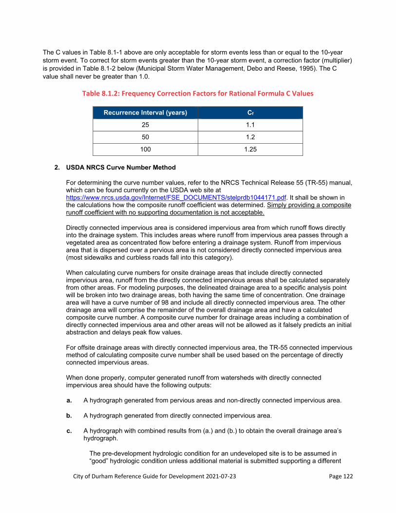
City of Durham Reference Guide for Development 2021‐07‐23 Page 122
The C values in Table 8.1-1 above are only acceptable for storm events less than or equal to the 10-year storm event. To correct for storm events greater than the 10-year storm event, a correction factor (multiplier) is provided in Table 8.1-2 below (Municipal Storm Water Management, Debo and Reese, 1995). The C value shall never be greater than 1.0.
Table 8.1.2: Frequency Correction Factors for Rational Formula C Values
Recurrence Interval (years) Cf
25 1.1
50 1.2
100 1.25
2. USDA NRCS Curve Number Method
For determining the curve number values, refer to the NRCS Technical Release 55 (TR-55) manual, which can be found currently on the USDA web site at https://www.nrcs.usda.gov/Internet/FSE_DOCUMENTS/stelprdb1044171.pdf. It shall be shown in the calculations how the composite runoff coefficient was determined. Simply providing a composite runoff coefficient with no supporting documentation is not acceptable.
Directly connected impervious area is considered impervious area from which runoff flows directly into the drainage system. This includes areas where runoff from impervious area passes through a vegetated area as concentrated flow before entering a drainage system. Runoff from impervious area that is dispersed over a pervious area is not considered directly connected impervious area (most sidewalks and curbless roads fall into this category).
When calculating curve numbers for onsite drainage areas that include directly connected impervious area, runoff from the directly connected impervious areas shall be calculated separately from other areas. For modeling purposes, the delineated drainage area to a specific analysis point will be broken into two drainage areas, both having the same time of concentration. One drainage area will have a curve number of 98 and include all directly connected impervious area. The other drainage area will comprise the remainder of the overall drainage area and have a calculated composite curve number. A composite curve number for drainage areas including a combination of directly connected impervious area and other areas will not be allowed as it falsely predicts an initial abstraction and delays peak flow values.
For offsite drainage areas with directly connected impervious area, the TR-55 connected impervious method of calculating composite curve number shall be used based on the percentage of directly connected impervious areas.
When done properly, computer generated runoff from watersheds with directly connected impervious area should have the following outputs:
a. A hydrograph generated from pervious areas and non-directly connected impervious area.
b. A hydrograph generated from directly connected impervious area.
c. A hydrograph with combined results from (a.) and (b.) to obtain the overall drainage area’s hydrograph.
The pre-development hydrologic condition for an undeveloped site is to be assumed in “good” hydrologic condition unless additional material is submitted supporting a different

City of Durham Reference Guide for Development 2021‐07‐23 Page 123
hydrologic condition. All normal pool water surfaces in SCMs or existing ponds/wetlands shall have a CN of 100.
3. Conversion of Impervious to Pervious Surface
In certain circumstances, impervious surface area may be removed and converted to pervious area in order to affect the Runoff Coefficient. In these circumstances, these areas of removed impervious must be clearly delineated and labeled on the site plan and construction drawings, with the following impervious-to-pervious conversion specifications included:
a. Remove all impervious surfaces from the subject area.
b. Till the area to a depth of 12 inches below the top of the compacted subgrade.
c. Provide soil amendments as needed in accordance with soil tests. If lime and/or fertilizer are to be used, it shall be applied uniformly during seedbed preparation and mixed well in the top 4 to 6 inches of soil or applied as recommended in the planting specifications for proposed landscaping.
C. Time of Concentration
The USDA NRCS Method segmented time of concentration (Tc) approach shall be used for computing times of concentration for both the pre-development and post-development condition. For the Tc analysis, the project site or drainage area shall be relatively homogeneous in terms of surface roughness, flow patterns (sheet, shallow concentrated, and/or channel flow), channel shape for channel flow, slope and land use. Sites or drainage areas that are not homogeneous with respect to these factors shall be subdivided into areas that are relatively homogenous, and a separate Tc flow path shall be established for each area. Multiple hydrographs will be needed and the hydrographs combined at the points of analysis. For discussions concerning the time of concentration flow path, refer to the TR-55 manual at https://www.nrcs.usda.gov/Internet/FSE_DOCUMENTS/stelprdb1044171.pdf.
An assumed minimum sheet/overland flow length of 75 feet in the pre-developed condition will be accepted by Stormwater Development Review provided that the area has not been altered such that overland sheet flow lengths would exceed 75 feet. This shall apply to flat slopes (2% or flatter) with predominantly B soil types. In no case shall sheet flow exceed 100 feet.
Refer to Figure 8.1-1 as an example of the format required for showing the segmented times of concentration paths on the drainage area maps. Multiple TC flow paths shall be evaluated, as depicted in Figure 8.1-1, in order to demonstrate the longest duration is used.
Post-development sheet flow length shall be no more than 50 feet unless it can be shown that the sheet flow depth is 0.10 feet or less. Sheet flow shall not exceed 100 feet.
Remaining overland flow along the flow path shall be shallow concentrated or channel flow as appropriate. Assumed cross-section geometry is not permitted; all cross-sections are to be based upon field conditions. Field data used to obtain cross-sectional geometry hydrologic model inputs for channels must be provided. Required field data includes but is not limited to surveyed/measured cross sections. A trapezoidal shape may be assumed provided the base width, bank slopes, top of bank height, and top width are all measured in the field.
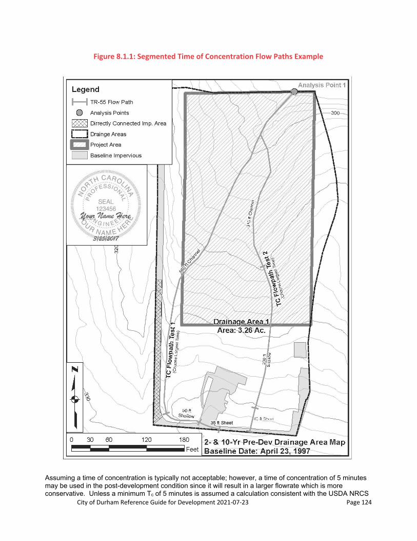
City of Durham Reference Guide for Development 2021‐07‐23 Page 124
Figure 8.1.1: Segmented Time of Concentration Flow Paths Example
Assuming a time of concentration is typically not acceptable; however, a time of concentration of 5 minutes may be used in the post-development condition since it will result in a larger flowrate which is more conservative. Unless a minimum Tc of 5 minutes is assumed a calculation consistent with the USDA NRCS

City of Durham Reference Guide for Development 2021‐07‐23 Page 125
Method shall be conducted for all subwatersheds. If the time of concentration is found to be less than 5 minutes in any calculation, a minimum time of concentration of five (5) minutes shall be used.
Refer to Table 8.1-4 below for the appropriate Manning’s n values for sheet flow as defined in the NRCS TR-55 manual.
Table 8.1.4: Manning’s n Values for Sheet Flow (Flow Depths of < 0.10 Feet)
Surface Description Manning’s n Values
Smooth Surfaces (concrete, asphalt, gravel or bare soil) 0.011
Short Grass 0.15
Dense Grass 0.24
Woods, light underbrush 0.40
Woods, dense underbrush 0.80
D. Precipitation
Design rainfall event precipitation depths shall be based on the NOAA Atlas 14 point precipitation frequency estimates (Atlas 14) or the rainfall depths listed in Table 8.1-5. Atlas 14 data can be obtained at this web address http://hdsc.nws.noaa.gov/hdsc/pfds/pfds_map_cont.html?bkmrk=nc. SIAs shall include a copy of the Atlas 14 map showing the selected region and precipitation tables specific to the site location.
Hydrologic modeling shall utilize the NRCS NOAA_B rainfall distribution or a site specific rainfall distribution developed using the NOAA Atlas 14 temporal distributions. WinTR-20 can be used to generate these site specific distributions. In all cases, the selected rainfall distribution shall be for 24-hour rainfalls.
Table 8.1.5: 24‐hour Design Precipitation Depths for Durham, NC
Average Recurrence Interval (years) Precipitation Depth (inches)
1-Year, 24-Hour 3.00
2-Year, 24-Hour 3.57
5-Year, 24-Hour 4.46
10-Year, 24-Hour 5.15
25-Year, 24-Hour 6.09
50-Year, 24-Hour 6.83
100-Year, 24-Hour 7.58
E. Peak Flow Calculations
Calculations for the pre- and post-development peak discharge rates for the 1-, 2-, 10- and 100-year (if required) 24-hour storm shall be conducted using TR-55/TR-20, HEC-1, HEC-HMS, or other software which incorporates these methodologies. The chosen method for calculating peak flow rates shall remain consistent throughout. Under no circumstance shall calculations switch from one modeling theory to another. Due to the lack of variability in rainfall distribution, the Rational Method may be used only on small projects with drainage areas less than 20 acres and where no stormwater control measures need to be modeled.
City of Durham Reference Guide for Development 2021‐07‐23 Page 126
Complete calculations and all supporting documentation (including but not limited to calculation of composite runoff coefficients, times of concentration [pre- and post-development], ditch/open channel analysis, storm drain analysis, culvert analysis, etc.) shall be submitted for review. This includes all assumptions used in the calculations and necessary channel cross-sections or pipe information used for the downstream analysis.
For computerized models, printouts of all model inputs and outputs must be provided so that Stormwater Development Review staff can verify them. A table summarizing the pre-development and post-development peak discharge rates with no backup information is not acceptable.
1. 1-Year Storm Event Analysis
a. If the post-development calculations show an increase in the pre-development 1-year peak discharge rate at a point of analysis, then peak discharge rate attenuation is required.
b. If the post-development calculations do not show an increase in the pre-development 1-year peak discharge rate at a point of discharge, then no further analysis is needed for that point of discharge.
c. Phased Developments
When a proposed development constitutes a portion of a common plan or phases are proposed, each phase must be able to stand alone for stormwater management or receive stormwater management from a preceding phase. A common plan has two options for satisfying the peak flow requirements.
i. The first option is to have post-development calculations on the first phase submittal reflect the ultimate build-out conditions for all phases of the development. Thus, all conveyances and/or SCMs would be sized for the ultimate project build-out. Note that when later phases are submitted for review and approval, those phases will be subject to the performance standards and ordinances that are effective at that time, and revisions to conveyances and SCMs may be required and proposed impervious surfaces must all be accounted for in the post-development weighted runoff coefficient.
ii. The second option is to include only the encumbered area (as platted) of the proposed phase and preceding phases in the project area and demonstrate it satisfies the peak flow requirements. Later improvements and SIAs shall include preceding phases in the calculations. Pre-development calculations shall reflect the site before any development has taken place (i.e. pristine conditions) – the earlier (previous phase) submittal(s) will not be considered as “existing” conditions for subsequent submittals. The subsequent submittal will be treated as a new site plan and, as such, subject to the performance standards and ordinances that are effective at that time. Consequently, revisions to conveyances and SCMs may be required using this option.
iii. Warning: Pre-development impervious area must reflect the impervious area on the site at the applicable baseline date for 1-year peak flow requirements (March 9, 2001 for land in the Falls Lake and Lower Neuse Basins, March 17, 2009 for land in the Jordan Lake Basin). All impervious area constructed after the baseline date must be reflected as post-development impervious only.
2. 2- and 10-Year Storm Event Analysis
a. If the post-development calculations show an increase of more than 10% from the pre-development 2- and 10-year peak discharge rates at a point of discharge, then a downstream analysis, peak discharge rate attenuation and/or downstream system improvements are required.

City of Durham Reference Guide for Development 2021‐07‐23 Page 127
b. If the post-development calculations do not show an increase in the pre-development 2- and 10-year peak discharge rates of more than 10% at each point of discharge, then no further analysis is needed.
c. If there is an increase of more than 10%, identify the downstream point at which the increase becomes less than 10%. Further analysis is required to determine the impacts of the increase between the site and the downstream point at which the increase becomes less than 10%.
Identify what features are located between the site boundary and the downstream point(s) along the drainage corridor (swales, ditches, open channels, culverts, pipe systems, SCMs, etc.). If there are no negative impacts along the drainage corridor, the SIA must specifically state and demonstrate that no structures (businesses, homes, culverts, streets, etc.) will be adversely impacted by the increase in peak discharge rates. If no structures exist between the site and each point of discharge, then the engineer must state this in the SIA. All negative impacts on existing improvements (e.g. streets, culverts, etc.) and development (e.g. businesses, homes, lawns, etc.) must be identified. All critical sites must be analyzed. SIAs are to include, but not necessarily be limited to, inlet and outlet calculations for culverts and channel capacity calculations for drainage ways and storm drain systems.
d. In areas known to have a history of flooding or drainage concerns, upstream or adjacent development will be held to more stringent standards for stormwater management unless the designer evaluates possible local or downstream flooding concerns and explores whether more stringent standards would be applicable.
e. Photographs must be provided for the representative downstream channel cross-sections and all culvert inlets and outlets.
f. If the downstream system is inadequate, contact Stormwater Development Review to discuss possible improvements and/or peak discharge rate attenuation requirements. If peak discharge rate attenuation is required, the post-development peak discharge rate must be managed back to or below the pre-development condition.
g. Phased Developments
When a proposed development constitutes a portion of a common plan or phases are proposed, each phase must be able to stand alone for stormwater management or receive stormwater management from a preceding phase. A common plan has two options for satisfying the peak flow requirements.
i. The first option is to have post-development calculations on the first phase submittal reflect the ultimate build-out conditions for all phases of the development. Thus, all conveyances and/or SCMs would be sized for the ultimate project build-out. Note that when later phases are submitted for review and approval, those phases will be subject to the performance standards and ordinances that are effective at that time, and revisions to conveyances and SCMs may be required and proposed impervious surfaces must all be accounted for in the post-development weighted runoff coefficient.
ii. The second option is to include only the encumbered area (as platted) of the proposed phase and preceding phases in the project area and demonstrate it satisfies the peak flow requirements. Later improvements and SIAs shall include preceding phases in the calculations. Pre-development calculations shall reflect the site before any development has taken place (i.e. pristine conditions) – the earlier (previous phase) submittal(s) will not be considered as “existing” conditions for subsequent submittals. The subsequent submittal will be treated as a new site plan and, as such, subject to the performance

City of Durham Reference Guide for Development 2021‐07‐23 Page 128
standards and ordinances that are effective at that time. Consequently, revisions to conveyances and SCMs may be required using this option.
iii. Warning: Pre-development impervious area must reflect the impervious area on the site at the applicable baseline date for 2- and 10-year peak flow requirements (April 23, 1997). All impervious area constructed after the baseline date must be reflected as post-development impervious only.
h. Site-to-Drainage Area Analysis
A site-to-drainage area analysis can be used to show that the site is a small percentage of the total watershed area. Further analysis is required between the site and the point of analysis of the total watershed area to determine the impact of the increase in peak discharge rates. See Table 8.1-6 below for percentage thresholds for using the site-to-drainage area analysis. The Site-to-Drainage Area Analysis cannot be used for the 1-year peak flow.
If the Site-to-Drainage Area analysis is used, a map outlining the total watershed area and the site area is required.
Table 8.1.6: Site‐to‐Drainage Area Thresholds
Proposed Land Use Threshold
~85% impervious
(e.g. commercial, business) If the total site area as a percentage of the total watershed area at
the analysis point is 2.5% or less, your analysis is complete.
~70% impervious
(e.g. townhouses) If the total site area as a percentage of the total watershed area at
the analysis point is 3% or less, your analysis is complete.
~35% impervious
(e.g. 1/4 acre single family homes)
If the total site area as a percentage of the total watershed area at the analysis point is 10% or less, your analysis is complete.
3. 100-Year Storm Event Analysis
a. New development shall not expand 100-year floodplains on previously developed or improved property or on property proposed to be improved. This requirement applies to floodplains not currently shown on Federal Emergency Management Agency (FEMA) maps. Improvements do not include SCMs, drainage structures, roads, tree save areas, or open space areas. No building or habitable structure, either proposed or existing, shall be flooded or have water impounded against it during the 100-year event. The engineer should check FEMA and City GIS maps for the presence of streams or ditches downstream of the project site that could overflow in the 100-year storm, and the presence of buildings or roads near those receiving conveyances. For questions concerning how this requirement is to be applied on a particular project, please contact Stormwater Development Review.
In areas known to have a history of flooding or flooding concerns, upstream or adjacent development may be held to more stringent standards for stormwater management. The designer shall consider possible local or downstream flooding concerns and explore whether more stringent standards would be applicable. Stormwater Development Review will advise the applicant when such a situation arises and require either a higher-order storm event be detained or additional engineering analysis be provided to fully justify not incorporating additional detention into the design.

City of Durham Reference Guide for Development 2021‐07‐23 Page 129
b. For 100-year analysis, software capable of modeling complex hydraulic calculations, such as backflow shall be used. Examples of software that satisfy this requirement are HEC-RAS, XPSWMM, and XPSLAMM.
8.1.4 Pollutant Removal Requirements
The City’s pollutant removal requirements are found in our Stormwater Performance Standards for Development, Section 70-739 through 70-741. All proposed developments must meet the applicable pollutant removal standards for nitrogen, phosphorus, total suspended solids (TSS) and other pollutants for which a Total Maximum Daily Load (TMDL) has been established for the area in which the project is located.
A. Nutrients
1. Exemption from Requirements: Pre-development and post-development land use maps, the most current version of the NC DEQ-approved stormwater nutrient accounting tool, and the Nutrient Reporting Form are not required to be submitted when a project meets the exempt criteria for stormwater pollutant standards in the City Code.
2. Stormwater Nutrient Accounting Tool
a. With the exception listed above, all development projects submitted for Stormwater Development Review are required to use the most current version of the NC DEQ-approved stormwater nutrient accounting tool (“the Tool”) to estimate nutrient loads in stormwater runoff and nutrient removal by stormwater control measures (SCMs).
b. The Tool was developed by North Carolina State University (NCSU) in coordination with the North Carolina Department of Environmental Quality (NCDEQ). More information on the Tool can be found at: https://deq.nc.gov/about/divisions/water-resources/planning/nonpoint-source-management/nutrient-offset-information.
c. Offsite areas that are not part of the project but drain to a project SCM (because runoff from these areas cannot practically be diverted from the SCM) should not be entered into the Tool. The SCM receiving the offsite runoff must be properly sized to handle the offsite run-on in addition to the onsite runoff. However, in general, credit cannot be given toward meeting minimum onsite nutrient removal percentages by treating offsite runoff.
d. If the project includes off-site roadway improvements within City maintained right-of-way, the area associated with the off-site roadway improvements shall be included in the Tool calculations. The project as a whole shall meet the applicable nutrient loading requirements, which may require over treatment on-site, treatment of the off-site roadway improvements, or treatment on-site of off-site right-of-way area.
e. Including Project Sidewalk in Right-of-Way in the Tool:
If project sidewalk is in NCDOT right-of-way (e.g., road is an NCDOT-maintained road):
o Since NCDOT does not want water from their right-of-way re-routed onto private property, if runoff from the project sidewalk in the right-of-way does not naturally flow onto the project site, the runoff from the project sidewalk should not be rerouted onto the site and the impervious area for the project sidewalk should not be accounted for in the Tool.

City of Durham Reference Guide for Development 2021‐07‐23 Page 130
o However, if runoff from the project sidewalk naturally flows onto the site it should be directed to a SCM on the site. When this occurs, the drainage area and impervious area for the project sidewalk must be accounted for in the sizing of the SCM. The project sidewalk should still not be accounted for in the Tool since this area is not in the City’s jurisdictional limits.
If sidewalk is in the City right-of-way (e.g., road is a City street): Impervious area from the project sidewalk must be accounted for in the Tool.
f. Land Uses: Please see the Tool User’s Guide developed by NCDEQ, which can be found at https://deq.nc.gov/about/divisions/water-resources/planning/nonpoint-source-management/nutrient-offset-information, and the memo on Interim Guidance for Jordan / Falls Stormwater Load Accounting Tool “Jurisdictional Lands” – Natural Wetlands, Open Water and Riparian Buffers.
Courtyards, patios, tennis courts, basketball courts, artificial turf fields, sidewalk not adjacent to pervious area, and other hard surfaced-like uses may use the land use category for Residential Driveway or Commercial Parking Lot. This is because the active use of this type of surface lends itself to tracking of dirt and spillables onto the surface, whereas a roof receives no foot traffic and therefore only gets atmospheric deposition of nutrients and particulate matter.
o When using these classifications for these surfaces, the engineer must clearly document this usage in the SIA.
o Document the utilization of this land use category in the hardcopy of the Tool printout submitted with the stormwater calculations as well. This should be done by hand writing double asterisks in the same column next to Driveway. Below the chart note the double asterisks and “Sidewalk – No Adjacent Pervious Area”. If there also happens to be a residential driveway use, then one would need to differentiate the breakdown by including the amount of sidewalk in the land use category description. For example, you would hand write in “7,560 ft2 Sidewalk – No Adjacent Pervious Area” next to the double asterisks below the chart. In addition, since there are two development categories, pre and post, differentiating the area could apply to both. An example of this would be 1,200 ft2 Sidewalk Pre-Development – No Adjacent Pervious Area and 7,560 ft2 Sidewalk Post-Development – No Adjacent Pervious Area. Of course, the total areas will be noted in the same row under the appropriate column(s) for Pre-Development and/or Post-Development.
Open/Landscaped is a non-residential category equivalent to lawn in the residential category.
Managed Pervious is landscaped areas, such as mulched areas with flowers, bushes, etc.
Unmanaged is pasture – note the high loading which is due to manure. This land use category is also used for areas which are not mowed on a regular basis, such as under high voltage transmission lines, graded areas behind building lots which will grow up, etc. Note that there is no unmanaged pervious category in the residential land uses.
Forest: For pre-development, it is the area with trees which one would consider forest. It would not be an area of trees under which one is trying to maintain lawn (we can assess this using aerial photography). For post-development, Forest would be the area within the delineation that is usually called tree line and outside of limits of disturbance.
City of Durham Reference Guide for Development 2021‐07‐23 Page 131
g. Multiple Regulatory Basins: If a project spans more than one of the City’s three Stormwater Regulatory Basins (Falls Lake Basin, Jordan Lake Basin, Lower Neuse River Basin (below Falls Lake), then a separate Tool must be developed for each separate regulatory basin.
Please use the Project Name field in the Project Info tab to make clear which regulatory basin is covered in that Tool spreadsheet. Each Tool spreadsheet should cover only the area in that regulatory basin.
It is possible and understood that due to grading, the total post-development area in a regulatory basin may not be the same as the pre-development area.
h. Representing SCMs in the Tool
In the “SCM Characteristics” tab, the Tool uses the concept of catchment areas in representing SCMs. A catchment area is all of the hydrologic area that drains to an analysis point. Larger projects or projects spanning ridge lines may have multiple catchment areas.
If more than one SCM is assigned to a single catchment in the Tool, the SCMs are assumed to operate in series (i.e. the outflow from SCM #1 flows into SCM #2, etc.). Thus, all of the area that drains to SCM #1 then drains to SCM #2. The upstream SCM should be entered as SCM #1 and the downstream SCM as SCM #2. A common example of SCMs in series is a wet pond followed by a level spreader/filter strip. The wet pond should be entered as SCM #1, and the level spreader/filter strip as SCM #2.
The downstream SCM in a catchment area may have some additional area draining to it that does not drain to the upstream SCM. Under SCM #2 in the catchment, only this incremental area should be entered, not the total area that drains to SCM #2.
Certain SCMs (e.g., dry ponds) may actually appear to add pollutants to the SCM effluent. On the Overall Summary tab, users should check the Effluent Mean Concentrations (EMCs) and loadings for Post-Project Whole Site w/ SCMs vs. the Post Project Whole Site w/o SCMs.
Oversized/Undersized SCMs: Per Section B.2 of the NC Stormwater Control Measure Crediting Document, some SCMs may be over- or undersized while others may not be. See Section B.2 of the NC Stormwater Control Measure Crediting Document on how to determine the percentage over- or undersized for those SCMs where it is allowed. This percentage is then entered into the Tool under “Percent of Full Size” field.
i. An electronic copy of the project Tool, in Excel format, must be included with each project review submittal.
3. Land Use Maps a. Pre-development and post-development land use maps are not required when a project
meets the exempt criteria for stormwater pollutant standards in the City code.
b. The applicant must provide pre- and post-development area land use maps illustrating the areas entered into the Tool Land Use Characteristics tab, to scale no smaller than 1 inch = 100 feet. The maps shall show the map scale, north arrow, and are to have the different land uses indicated in the Tool either hatched or shaded with land use coding indicated in a legend on the maps. All land uses used in the Tool must be shown in the legend. In addition, the area associated with each land use must be quantified, in square feet, on the exhibit.

City of Durham Reference Guide for Development 2021‐07‐23 Page 132
c. The applicant must also provide SCM drainage area land use maps illustrating the areas entered into the Tool SCM Characteristics tab, to scale no smaller than 1 inch = 100 feet. The maps shall show the map scale, north arrow, and are to have the different land uses indicated in the Tool as draining to each SCM either hatched or shaded with land use coding indicated in a legend on the maps. All land uses draining to an SCM must be shown in the legend. In addition, the area associated with each land use must be quantified, in square feet, on the exhibit.
4. Area of Concern Spreadsheet a. The Area of Concern (AoC) methodology is intended to be used for expansion projects where
much of the existing impervious on the site was left untouched as part of the project. It was developed so that projects on sites with existing impervious areas that pre-dated the applicable nutrient baseline date would not be penalized for that impervious area. Use of the AoC methodology is optional, not mandatory.
b. The AoC method can only be used for projects that will be complying with Paragraph (a), “Nutrient Loading Limits” in Section 70-740 of the Stormwater Performance Standards for Development ordinance. It cannot be used to comply with any of the other compliance alternatives in this section.
c. The AoC spreadsheet can be downloaded from the Stormwater Development Review website at http://durhamnc.gov/DocumentCenter/View/3087. The method is based on the amount of “new” impervious area cumulative since the baseline date, including the impervious to be laid down as part of the project. "New" impervious area is defined as the existing non-impervious land to be converted to impervious surface, plus the existing impervious area that is to be removed and replaced with new impervious surface. All calculations are based on the “new” impervious area. An example calculation for new impervious area is provided below.
d. The AoC area is then calculated as the “new” impervious ÷ the post-development % impervious. Based on this total area, pre-development and post-development land uses are constructed based on a mirror of the entire site shrunk down/pro-rated to cumulatively make up the total AoC area.
e. Step 1: Complete a Tool spreadsheet for the entire project site.
The pre-development land use areas should be based on what existed as of the applicable nutrient baseline date.
Post-development land use areas should be based on what will exist after the project is complete.
All SCMs that will exist on-site after the project is complete should be represented in the “SCM Characteristics” tab, with the correct land uses of the actual drainage area draining to each SCM represented.
The Project Name and Project Description fields in the Project Info tab of the Tool should make it clear that this particular spreadsheet is for the entire site.
f. Step 2: Complete the Area of Concern spreadsheet. As stated in the Instructions tab of the spreadsheet, the TOTAL SITE portion of the spreadsheet should be filled out first based on the Tool for the entire project site. After the New Impervious Area cell is filled in, the AoC land use areas cells will calculate.
g. Step 3: Complete a Tool spreadsheet for the Area of Concern:

City of Durham Reference Guide for Development 2021‐07‐23 Page 133
Fill out the Land Cover Characteristics tab in the AoC Tool spreadsheet based on the pre- and post-development land uses areas calculated by the AoC spreadsheet.
The pre-development and post-development AoC nitrogen and phosphorus loading rates from the AoC Tool (in lbs/acre/year) should be the same as the pre- and post-development nitrogen and phosphorus loading rates for the entire site. The benefit of using the AoC is that the acreage of the AoC is smaller than that of the entire site, so the number of pounds of nitrogen or phosphorus that must be removed on-site or offset using an off-site nutrient bank is much less.
Only the SCMs that receive and treat runoff from new impervious area should be represented in the Tool for the Area of Concern. Thus, although the pre- and post-development nutrient loading rates will be the same for both versions of the Tool, the nutrient loading rates for the post-development with treatment scenario will not.
The Project Name and Project Description fields in the Project Info tab of the Tool should make it clear that this particular spreadsheet is for AoC only.
h. An electronic copy of the Tool spreadsheet for the entire site, the AoC spreadsheet, and the AoC Tool spreadsheet, all in Excel format, must be included with each project review submittal unless project is exempt from stormwater pollutant standards.
i. AoC Example: For an example of how to use the AoC, see the Area of Concern (AoC) Worksheet for use with Falls/Jordan Stormwater Accounting Tool (XLS) link at our web page http://durhamnc.gov/895/Stormwater-Development-Review . See the first tab “Instructions, Example”.
5. Nutrient Reporting Form
a. NCDEQ has required that the City use standardize reporting forms where offset mitigation is proposed. DEQ developed standard forms for projects in the Jordan Lake Basin, and the Neuse, Tar-Pamlico and Falls Lake Basins.
b. The City of Durham consolidated these two separate forms into one, and to adapt the form specifically to the nutrient standards and compliance options in the City’s Stormwater Performance Standards for Development ordinance.
c. The Nutrient Reporting Form should be filled out based on Tool results. If the AoC method is used for the proposed project, the Nutrient Reporting Form should be filled out based on results of the Tool for the Area of Concern.
d. Nutrient Reporting Form tab – although in Excel, this tab replicates the layout and information required in the standard forms developed by DEQ.
Information at the top of the form under the PROJECT INFORMATION heading should be filled out completely.
Under the WATERSHED INFORMATION section, please check the box for the appropriate Basin, and provide the Watershed ID. Use the links provided to determine the Watershed ID.
If the project is in the Jordan Lake, fill in the Jordan Lake Delivery Factor for the site only. The delivery factor for the Bank and the name of the Bank is not required at this time.

City of Durham Reference Guide for Development 2021‐07‐23 Page 134
Under the NUTRIENT OFFSET REQUEST section, fill out only the Project Size cells in yellow. The Project Size value should match the Total Development Area from the Tool. All other values will be calculated by the spreadsheet.
If the AoC method is used for the proposed project, the Total AoC Area would be filled in for the Project Size.
e. Compliance Worksheet tab – this spreadsheet calculates the:
Target post-development loading rate, depending on the nutrient compliance alternative selected from the Stormwater Performance Standards for Development ordinance, and
The required nutrient loading reduction that must be achieved.
f. The four nutrient compliance alternatives referenced in the City Code of Ordinances are:
Nutrient loading limits and on-site treatment minimum (Ordinance Sections 70-740(a) and Sections 70-741(a))
Alternative percentage reduction option for Redevelopment that increases impervious area (Ordinance Section 70-740(b))
Alternative percentage reduction option for Redevelopment that does not increase impervious area (Ordinance Section 70-740(c))
Alternative for low impact development in Falls Basin (Ordinance Section 70-740(d))
To aid the user in determining the appropriate alternative for the project in question, the ordinance text for the four alternatives is presented in different colored sections (as shown above) that quote directly from the ordinance.
The values calculated in the Compliance Worksheet tab are then propagated over into the Nutrient Reporting Form tab to determine:
Whether the required on-site reduction is being achieved, and
The pounds of nutrient offsets that must be purchased to bring the project into compliance.
g. If the Compliance Worksheet tab and the Nutrient Reporting Form tab indicate that the required on-site reduction is not being achieved, additional treatment by SCMs will be necessary for project approval.
h. If the project is not subject to nutrient requirements, the reason for exemption must be indicated in the last part of the Compliance Worksheet tab, under “Exempt from Stormwater Pollutant standards (Section 70-739)”.
i. An electronic copy of the project Nutrient Reporting Form, in Excel format, must be included with each project review submittal.
6. Nutrient Buy-Down Payments
a. The Nutrient Reporting Form calculates the amount of offsite credits needing to be purchased to bring the project into compliance with City nutrient requirements – this is shown under the “State Buy Down Amount Delivered (lbs)” cells for nitrogen and phosphorus.
City of Durham Reference Guide for Development 2021‐07‐23 Page 135
b. An additional 5% credits must be purchased if the bank that the credits are purchased from is not within City of Durham limits. This is also quantified on the Nutrient Reporting Form.
c. Stormwater Development Review will prepare a letter stating the number of pounds of nitrogen and phosphorus credits, including the additional 5% credits, that must be purchased. This letter must be presented to the nutrient bank when purchasing credits. Applicants are required to buy credits from private mitigation banks if they are available; see https://deq.nc.gov/about/divisions/water-resources/water-resources-permits/wastewater-branch/401-wetlands-buffer-permits/401-nutrient-offset-buffer-mitigation-program for a list of private mitigation banks.
d. The private mitigation bank from which the credits are purchased must be located as follows:
For projects in the Falls Basin, the bank must be located in the upper Falls Lake Basin, which is the portion of Falls Lake lying to the north/west of Highway 50.
For projects in the Jordan Basin, the bank must be located in the Upper New Hope Creek area.
For projects in the Neuse Basin below Falls Lake, the bank must be located within the Neuse River Basin but outside the Falls watershed.
e. If there are no private mitigation banks with credits available, the applicant may buy credits from the NC DEQ Division of Mitigation Services. For further information about in-lieu fee mitigation, see https://deq.nc.gov/about/divisions/water-resources/water-resources-permits/wastewater-branch/401-wetlands-buffer-permits/401-nutrient-offset-buffer-mitigation-program.
f. Prior to issuance of any approvals contingent on the purchase of offsite nutrient credits, the City requires a copy of the credit purchase receipt and the bank’s post-purchase credit ledger.
g. Nutrient credit purchases for phased projects: If the development will be phased, nutrient credits must be purchased for each phase prior to construction drawing approval for that phase. The credits required for each phase shall be proportional to the nutrient loading contribution of that phase.
B. Total Suspended Solids
Requirements for the treatment of Total Suspended Solids (TSS) in runoff from development are found both in the Unified Development Ordinance administered by the City-County Planning Department, and the Stormwater Performance Standards for Development administered by the Public Works Department. Compliance with each of these must be discussed in the SIA narrative.
1. Unified Development Ordinance (UDO) Section 8.7 Watershed Protection Overlay Standards
a. Development in a Watershed Protection Overlay is subject to limits on the amount of impervious surfaces permitted. Where development proposes intensity greater than the maximum authorized by the Low Density Option, engineered stormwater controls must be used to control stormwater runoff from the first inch of rainfall in order to meet water quality concerns. Although the Planning Department is responsible for ensuring that these requirements are met, Section 8.7.2.D states that The City Public Works Director designee, is responsible for approving plans and specifications for the proposed engineered stormwater controls.
City of Durham Reference Guide for Development 2021‐07‐23 Page 136
b. Per 15A NCAC 02B .0624 WATER SUPPLY WATERSHED PROTECTION PROGRAM: NONPOINT SOURCE AND STORMWATER POLLUTION CONTROL, controlling the runoff from the first inch of rainfall means that the runoff from the first inch of rainfall is captured and routed to a stormwater control measure that achieves either “runoff treatment” or “runoff volume match”.
2. Stormwater Performance Standards for Development Section 70-740(e): This paragraph of the ordinance states “When the impervious percentage of a Development that increases impervious area equals or exceeds 16% in the Falls or Jordan Basins, or 24% in the Lower Neuse Basin, TSS removal is required as further described in this subsection (e). All impervious surfaces, as reasonably practical, must drain to an SCM that is designed to provide a minimum of 85% TSS removal and is sized to capture runoff from the first 1 inch of rainfall from all surfaces that drain to the SCM. These requirements are expanded, and/or modified as follows…”
a. “as reasonably practical”: If the design engineer feels that it is not reasonably practical to capture runoff from all impervious surfaces, it is his/her responsibility to state in the SIA narrative the reason why it is not reasonably practical. Evidence to support this must also be provided, such as documentation that it is not feasible to capture the runoff from the impervious surfaces in question and route it by gravity to an SCM, as well as why the impervious area expansion cannot occur in a different location which would allow it to be captured.
b. Overtreatment to address untreatable areas: Per Section 70-740(e)(2), “Where treatment for TSS is not reasonably practicable, as determined by the Department, such as when impervious areas include offsite transportation improvements or small noncontiguous areas at the edge of a project, additional reductions of TSS may be required in treatable areas, such as overtreatment in other project areas or treatment of offsite run-on”.
The examples given are for offsite areas and small noncontiguous areas at the edge of a project. Not treating significant contiguous areas such as the rear of residential structures is not an example or implied. In general, the City will not make any exceptions for the rear of houses, associated patios, etc. in single family residential high density developments in watershed protection overlays.
If “treatment in lieu” is provided, the engineer must clearly document with maps and quantify with calculations what areas are being treated in lieu of areas that are impractical to treat.
c. Composite treatment: Due to changes at the state level in the way SCMs are credited with pollutant removal, composite TSS removal calculations using 90% TSS removal ponds will no longer be allowed. However, composite TSS removal for SCMs in series will still be allowed. Please see the NC DEQ Archived Stormwater Design Manual 2009-2016 (https://deq.nc.gov/about/divisions/energy-mineral-land-resources/energy-mineral-land-permit-guidance/stormwater-bmp-manual/archive) as follows:
Section 3.9.4 for the equation used for calculating pollutant removal for SCMs in series, and
Section 4.4, Table 4-1 for the TSS removal efficiency for various SCM types.
d. Piped flow: Projects that do not require construction of SCMs because their impervious percentage is less than the percentages shown in Sec. 70-740(e) of the City Code must treat TSS from stormwater runoff that is conveyed in non-vegetated conveyances, such as stormwater pipes, but excluding road and driveway crossings. The low density of such projects should provide the room needed for overland sheet flow and grassed swales to convey runoff to the maximum extent practical (MEP). A guideline for MEP is 30 feet for

City of Durham Reference Guide for Development 2021‐07‐23 Page 137
general overland flow over a vegetated surface; if the flow is conveyed in a vegetated channel, 5:1 side slopes in addition to a 100-foot travel distance are the target, with base width of channel maximized so that velocities do not exceed limits as specified in the NC Erosion & Sediment Control Planning and Design Manual.
C. TMDL Pollutants
A Total Maximum Daily Load (TMDL) is the maximum amount of a pollutant that a body of water can receive while still meeting water quality standards. In North Carolina, TMDLs are developed by the NC Department of Environmental Quality for water bodies that are considered impaired for a particular pollutant, i.e., do not meet a water quality standard which is affected by that particular pollutant.
In North Carolina, the list of waters that are impaired (known as the “303(d) list” after Section 303(d) of the Clean Water Act) is updated every two years based on monitoring data. At this time, the most current 303(d) list for North Carolina can be found at https://deq.nc.gov/about/divisions/water-resources/planning/modeling-assessment/water-quality-data-assessment/integrated-report-files. If this link is broken in the future, Google “NC 303(d) list” to find the relevant web pages. The most current list of TMDLs can be found at https://deq.nc.gov/about/divisions/water-resources/planning/modeling-assessment/tmdls/draft-and-approved-tmdls. If this link is broken in the future, google “NC TMDL” to find the relevant web pages.
1. Bacteria Removal:
a. Per Section 70-741(d) of the Stormwater Performance Standards for Development, if a development project requires SCMs in order to comply with that ordinance, and the project is located in an area that is subject to a TMDL for bacteria, at least one SCM for each stormwater discharge must be rated as medium or high for its ability to remove bacteria from stormwater.
b. The applicability of these bacteria removal requirements, and the proposed method of compliance, must be discussed in the narrative portion of the SIA. If there is no TMDL for bacteria for the watershed in which the project is located, the narrative should clearly state this.
2. Other Pollutants:
a. SCMs required to be constructed under the Stormwater Performance Standards for Development must also treat any other pollutant for which a TMDL has been identified for the watershed area within which the SCM is located.
b. The applicability of other TMDLs to the watershed area in which the project is located, and the proposed method of compliance with those TMDLs, must be discussed in the narrative portion of the SIA. If there are no other TMDLs for the watershed in which the project is located, the narrative should clearly state this.
D. Spill Prevention and Counter Measure Plan for Service Stations,
Vehicle Repair Shops and Junk Yards
UDO Section 5.3.4, “Commercial Use Standard” requires a spill prevention and counter measure plan (SPCP) for the following commercial uses:
Convenience Stores with Gas Sales,

City of Durham Reference Guide for Development 2021‐07‐23 Page 138
Vehicle Service, and Vehicle Service Limited, and
Wrecking, Junk and Salvage Yards
Requirements for the SPCP are as follows:
1. A spill prevention and counter measures plan shall be provided prior to construction drawing approval that includes, at a minimum:
a. Clean up procedures for (fuel or other hazardous material) spills occurring inside and outside the building;
b. Counter measures for use in preventing (fuel or other hazardous material) spills from entering the stormwater collection system; and
c. Routine cleanup procedures for work areas and parking areas. Washdown water shall not be permitted to enter the stormwater collection system.
2. The SPCP must be submitted to Stormwater Development Review.
3. The following are acceptable for the SPCP:
a. A plan that meets the federal Spill Prevention Control and Countermeasure requirements in Title 40, Section 112 of the Code of Federal Regulations (40 CFR 112).
b. A plan that meets the Stormwater Pollution Prevention Plan requirements set forth in the North Carolina NPDES General Permit that covers stormwater discharges for the relevant industrial sector.
c. A plan developed using the City of Durham’s Spill SPCP template.
8.1.5 Potential SCM Location Issues
A. Seasonal High Water Table
The seasonal high water table (SHWT) elevation is a significant concern for most types of SCMs. Filtration-type SCMs typically need a required minimum vertical separation between the bottom of the SCM and the SHWT so as not to dewater the SHWT and not to occupy capacity in the filtration SCM with groundwater. Other SCMs, such as wet ponds and wetlands that operate using a normal pool for pollutant removal, function better if they intersect the SHWT.
A report documenting the determination of the SHWT elevation is required prior to construction drawing approval by Stormwater Development Review. However, because the SHWT elevation is critical to the location and type of SCM, the City highly recommends that this elevation be established prior to site plan approval. If a review of the SHWT report submitted with the construction drawings reveals that the proposed SCM will not meet the SHWT design criteria, a site plan amendment may be required to change the SCM to a different type.
The “Separation from Seasonal High Water Table (SHWT)” section of Chapter A-3 of NC DEQ Stormwater Design Manual provides requirements for the hydrogeologic evaluation that must be used to establish the SHWT. The City requires a report of this evaluation be submitted with the construction drawings. In addition to the NC DEQ requirements, the hydrogeologic evaluation report must also meet the following:

City of Durham Reference Guide for Development 2021‐07‐23 Page 139
1. The report needs to clearly state the elevation of the SWHT based on a particular datum (ex. NAVD 88). The distance below ground surface (e.g., in inches or feet) is not an acceptable quantification of the SHWT elevation.
2. The ground surface elevation must be established using an instrument (e.g., automatic level, survey grade GPS unit, etc.) accurate to the nearest tenth of a foot. The report must state what type of unit was used to establish the ground surface elevation.
B. Contaminated Soils
Per General MDC #2, SCMs that allow stormwater to infiltrate shall not be located on or in areas with contaminated soils. Infiltration SCMs include bioretention cells, sand filters that are open on the bottom, permeable pavement, and depending upon native soils, vegetated swales, level spreader-filter strips, and berms.
To determine if there is a potential for contaminated soils, a Phase I Environmental Site Assessment can be conducted, or the State and federal Brownfields websites can be consulted at:
http://durhambrownfields.com/properties/ for properties identified for the Durham Brownfields program,
http://deq.nc.gov/about/divisions/waste-management/brownfields-program for identified brownfields sites in North Carolina,
https://www.epa.gov/brownfields for nationally-identified brownfields sites,
https://deq.nc.gov/about/divisions/waste-management/waste-management-rules-data/waste-management-gis-maps for maps of site regulated by the NC DEQ’s Division of Waste Management’s Superfund Section,
http://deq.nc.gov/about/divisions/waste-management/ust/databases for North Carolina underground storage tank databases, and
F. SCM Size
Although Stormwater Development Review does not review the SCM sizing calculations until the construction drawing stage, we highly recommend that the design engineer run the sizing calculations at the site plan stage to ensure that there is adequate space allocated for the proposed SCM(s) and the required SCM access and maintenance easement(s) to and around the SCMs.
D. Floodplain
Per FEMA regulations, a Floodplain Development Permit is required before the start of any construction or development located within a Special Flood Hazard Area (SFHA). This includes the construction of SCMs within a SFHA. The Design Services Center issues all floodplain development permits, please contact the Center for further information on these permits.
If an earthen dam embankment is proposed within the limits of the 1% Annual Chance Floodplain (also known as the 100-year floodplain), the downstream toe of the embankment fill shall be at or above the 25-year (4% annual chance flood) water surface elevation. The 25-year floodplain is often only a few feet narrower than the 100-year floodplain. See the City of Durham Addendum to the NC DEQ Stormwater Best Management Practices Manual, found in Section 8.3, for further information on this requirement.

City of Durham Reference Guide for Development 2021‐07‐23 Page 140
E. SCMs Located in a Public Utility Easement
If an SCM is proposed in a public-utility easement, documentation from the public utility company showing approval of the proposed SCM shown on a referenced plan sheet must be submitted as part of the Stormwater Impact Analysis. This documentation is to include at a minimum:
1. All legal documents that relate to the establishment of this public-utility easement, restrictions applicable to the easement, and what can and cannot be done by others in this easement.
2. Statements on certain sheets of the site plan that “structures and other developmental restrictions are imposed within the easement”.
3. Documentation from the easement holder that it is permissible to construct the SCM in the easement, and that the easement holder will not perform any construction or maintenance activities in the easement that will interfere with the functioning of the stormwater facility.
4. Identification of any perpetual indemnity the developer proposes to provide to the City of Durham in the event of a conflict with the easement holder regarding its easement rights and potential interference with the SCM.
5. A granted permanent easement to the developer for the location of the SCM in the public-utility easement.
8.1.6 Diffuse Flow into a Riparian Buffer
The Riparian Buffer Protection rules require diffuse flow of stormwater runoff to be maintained in the riparian buffer by dispersing concentrated flow from the proposed project into a riparian buffer. The Table of Uses within these rules details specific activities in riparian buffers that are designated as exempt, allowable, allowable with mitigation, or prohibited.
Use one of the following four options provided by NC DEQ in their March 7, 2014 guidance document “Options for Meeting Diffuse Flow Provisions of the Stormwater and Riparian Buffer Protection Programs” (https://files.nc.gov/ncdeq/Energy%20Mineral%20and%20Land%20Resources/Stormwater/Public%20Notices/TRW%20Diffuse%20Flow%20Options%2003-07-14.pdf):
1. A Level Spreader-Vegetated Filter Strip (LS-VFS) designed to handle the one inch/hour storm intensity and larger storms may be discharged non-erosively, or an alternate design that creates uniform shallow flow across a vegetated filter strip in an equivalent or better manner.
2. An SCM that removes a minimum of 30% of TN removal outside of the vegetated or riparian buffer to treat the design storm before it is discharged through the buffer via:
a. A new drainage ditch, roadside ditch or stormwater outfall (Note: This activity is allowable in the buffer per the Table of Uses. Approval of a No Practical Alternatives Application [NPAA] by the jurisdictional authority [NC DEQ for the Neuse River Basin, City of Durham for the Jordan Lake Basin] is required); OR
b. An outlet pipe discharging into a dissipation device as diffuse flow as long as the maximum velocity in the stream buffer (not on the outlet dissipation pad) for the ten-year storm is non-erosive. NC DEQ has advised that in the wooded Zone 1 (inner 30 feet of buffer closest to stream), a velocity of 2 feet per second would be considered non-erosive for the 10-year event, although this does depend on slope.
3. A vegetated conveyance designed to infiltrate the design storm (for lower SHWT and soils with good infiltration rates).
City of Durham Reference Guide for Development 2021‐07‐23 Page 141
4. A vegetated conveyance designed as a wetland swale with an appropriately designed outlet system (for high SHWT and/or soils with poor infiltration rates).
Per 15A NCAC 02H.1003, “REQUIREMENTS THAT APPLY TO ALL PROJECTS”, Paragraph (5), “STORMWATER OUTLETS”, “Stormwater outlets shall be designed so that they do not cause erosion downslope of the discharge point during the peak flow from the 10-year storm event as shown by engineering calculations.” Per 15A NCAC 02H.1002, “DEFINITIONS”, Paragraph (26), " ‘Non-erosive velocity’ means the flow rate of water, usually measured in feet per second, that does not exceed the maximum permissible velocity for the condition and type of soil and groundcover over which the water is flowing. Erosion occurs when the maximum permissible velocity is exceeded."

City of Durham Reference Guide for Development 2021‐07‐23 Page 142
Section 8.2: Supplemental Stormwater
Development Requirements
This section provides criteria for meeting City Stormwater Standards for development items associated with stormwater control measure plan review, platting, and construction. This section will be further supplemented in the future to document and clarify accompanying Stormwater Development Review items required throughout the development review process.
8.2.1 Provisions for Declaration for Covenants, Conditions &
Restrictions
Final plats to be recorded for any residential development that requires a stormwater control measure(s) and which the dwellings or units will be sold to private individuals is required to have an owners association established in accordance with the NC Secretary of State’s requirements. This nonprofit corporation (the owners association) shall oversee the Declaration of Covenants, Conditions and Restrictions (CC&Rs) established for the development to maintain the open space and/or common area that are part of it.
The City of Durham requires that both the owners association and the CC&Rs are established prior to or at the time of final plat recording for any development that incorporates an owners association. The CC&Rs shall include the standard language shown below and shall be submitted to Stormwater Development Review electronically at [email protected] in conjunction with the submission of any final or condo plat for any development that has approved stormwater control measures as part of it. The required language shall be clearly marked or highlighted to distinguish it from the other text in the document. Leaving these required items unaddressed will delay stormwater approval of the plat dictating the need for this.
Mandatory language required for the Declaration of Covenants, Conditions and Restrictions:
ARTICLE (fill in) Obligations Regarding Stormwater Facilities
The Property includes one or more stormwater management facilities (hereafter “Facility/ies”) that is/are the perpetual responsibility of the Association. Such Facilities are subject to the Durham City Code, Chapter 70, Article X, Section 70-743 (Inspection, Maintenance, Repair, and Reconstruction) and is binding on the Association. The Facilities, associated easements, and stormwater notes are or will be shown on a plat(s) recorded with the Durham County Register of Deeds. The Property subject to the above section of the Durham City Code is the “Property” referred to in this Article. The Stormwater Facilities must be maintained in accordance with City Requirements, which include all ordinances, policies, standards, and maintenance protocols. In particular the City’s current “Owner’s Maintenance Guide for Stormwater BMPs Constructed in the City of Durham” (available at the time of recording this document at http://durhamnc.gov/DocumentCenter/View/2239/Owners-Maintenance-Guide-for-Stormwater-BMPs-PDF?bidId= and the operation and maintenance manual prepared specifically for the Facility/ies containing requirements that apply to the Association’s Facilities.
Nothing in the remaining Article of these Restrictive Covenants filed by Declarant as part of this Declaration or any subsequent modifications of this Declaration may reduce the Association’s or Lot Owners’

City of Durham Reference Guide for Development 2021‐07‐23 Page 143
obligations with regard to the Facility/ies. Such additional covenants may increase the obligations or provide for additional enforcement options.
The Stormwater Facility/ies and their location are as follows: (Insert below the description of Facilities as well as Plat Book citation and/or Lot identification)
In addition to the above obligations, the Association’s obligations with regard to the Facilities are:
1. Inspections/Routine Maintenance. In accordance with City Requirements, the Association shall cause the Facility/ies to be inspected i) annually; and, ii) after major storm events that cause visual damage to the Facility; and iii) upon notification from the City to inspect. The inspection shall be performed by a licensed North Carolina Professional Engineer or a North Carolina Registered Landscape Architect certified by the City who shall document those things mandated under City Requirements. The inspection shall occur annually during the month in which the Facility/ies as-built certification was accepted by the City, which month may be determined through contact with the City of Durham Department of Public Works, Stormwater Division. The inspection shall be reported to the City as further described below.
2. Repair and Reconstruction. The Association shall repair and/or reconstruct the Facility/ies as it determines is necessary, and, at a minimum, as set forth in City Requirements or as directed by the City to allow the Facility/ies to function for its intended purpose, and to its design capacity. The Association shall provide written reports regarding major repair or reconstruction to the City in accordance with City Requirements.
3. Stormwater Budget Line Items & Funding. The dues of the Association shall include amounts for upkeep and reconstruction of the Facilities which shall be included in dues charged to Lots or members from the point that Lots or members are charged dues for other common purposes. The Association shall maintain two (2) separate funds in its budget for the Facility/ies. The first, the “Inspection and Maintenance Fund,” shall be for routine inspection and maintenance expenditures and shall be used for annual inspections, maintenance, and minor repairs. The funds for this purpose may be maintained as part of the Association’s general account. The second fund, the “Major Reconstruction Fund,” shall be a separate, increasing reserve fund that will build over time and provide money for major repairs to and eventual reconstruction of the Facility/ies. The Major Reconstruction Fund shall be maintained in an account that is separate account from the Association’s general account as described below. At a minimum, the Association shall, annually, earmark (Insert $ amount after consulting Stormwater Development Review) from its collected dues for the Inspection and Maintenance Fund and (Insert $ amount after consulting Stormwater Development Review) for the Major Reconstruction Fund. These minimum amounts shall be increased annually by 3% per year over the prior year’s amount. The Association may set a higher amount in its discretion, or if directed by Durham Director of Public Works after an examination of the Facility/ies. The Association shall set dues at a sufficient amount to fund each of the two line items in addition to the Association’s other obligations. The Association may compel payment of dues through all remedies provided in these Covenants or otherwise available under law.
4. Assessments/Liens. In addition to payment of dues, each Lot shall be subject to assessments by the Association for the purpose of fulfilling the Association’s obligations under this Article. Such assessments shall be collected in the manner set forth in these Covenants. As allowed under NCGS §47F, or successor statutes, or, for condominiums, as allowed under NCGS 47C, or successor statutes, all assessment remaining unpaid for 30 days or longer shall constitute a lien on the Lot. Such lien and costs of collection may be filed and foreclosed on by the Association. In addition, the Association’s rights may, in the discretion of the City, be exercised by the City, as a third party beneficiary and/or as Attorney in Fact for the Association.
5. Stormwater Expenditures Receive Highest Priority. Notwithstanding any contrary

City of Durham Reference Guide for Development 2021‐07‐23 Page 144
provisions of the covenants of which this Article is a part, to the extent not prohibited by law, the inspection, maintenance, repair, and replacement/reconstruction of the Facility/ies shall receive the highest priority (excluding taxes and assessments and other statutorily required expenditures) of all Association expenditures.
6. Separate Account for Major Reconstruction Fund. Engineer’s Report. The Association shall maintain the Major Reconstruction Fund for the Facility/ies in an account separate from the Association’s general account. The Association shall use the Fund only for major repairs and reconstruction of the Facility/ies. No withdrawal shall be made from this fund unless the withdrawal is approved by two Association officials who shall execute any documents allowing such withdrawal. Prior to withdrawing funds from this account, the Association shall (i) obtain a written report from an engineer approved in accordance with City Requirements regarding repairs or reconstruction needed and approximate cost of such repair or reconstruction; and (ii) submit such report to the Director of the City’s Department of Public Works, and notify the Director of the repairs or reconstruction to be undertaken on the Facility, the proposed date, and the amount to be withdrawn from the Major Reconstruction Fund. In the event of an emergency, withdrawal and expenditure of funds may be made after telephone notification to the Stormwater Services Division of the Department.
7. Annual Reports to City. The Association shall provide to the City annual reports in substance and form as set forth in City Requirements. At a minimum each report shall include:
a. the annual Facilities inspections report described in section (1) above;
b. if requested by City, a description of repairs exceeding normal maintenance that have been performed on the Facility/ies in the past year, and the cost of such repairs;
c. if requested by City, a bank or account statement showing the existence of the separate Major Reconstruction Fund described in Section (6) above and the balance in such fund as of the time of submission of the report;
d. if requested by City, the amount of Association dues being set aside for the current year for each of the two stormwater funds – the Inspection and Maintenance Fund and the Major Reconstruction Fund.
8. Facility/ies to Remain with Association; Lot Owners’ Liability. To the extent not prohibited by law, the Facility/ies shall remain the property of the Association and may not be conveyed by the Association. In the event the Association ceases to exist or is unable to perform its obligations, all Lot Owners, excluding the Lots owned by the Association, shall be jointly and severally liable to fulfill the Association’s obligations. Such Lot Owners shall have the right of contribution from other owners with each Lot’s pro rata share being calculated as Lot Owner’s proportional obligations are otherwise defined in these Covenants. The City may also exercise rights described in the Durham City Code and other remedies provided by law.
9. City Rights; Liens Against Owners. In addition to rights granted to the City by ordinance or otherwise, the City shall have the following rights, generally summarized below:
a. Direct the Association in matters regarding the inspection, maintenance, repair, and /or reconstruction of the Facility/ies;

City of Durham Reference Guide for Development 2021‐07‐23 Page 145
b. If the Association does not perform the work required by ordinance or by these covenants, do such work itself, upon 30 days’ written notice to the Association.
c. Access the Facility/ies for inspection, maintenance, and repair, crossing as necessary the lot(s) on which the Facility/ies are located and all other private and public easements that exist within the Property subject to these covenants.
d. Require reimbursement by the Association of the City’s costs in inspecting, maintaining, repairing, or reconstructing the Facility/ies.
Enforce any debts owed by the Association against Lot Owners if such debts are not fully paid by the Association. The debt may be allocated to Lot Owners as provided in the other sections of these Covenants, and may be made a lien on each owner’s
10. No Dissolution. To the extent not prohibited by law, the Association shall not enter into voluntary dissolution unless the Facility is transferred to a person who has been approved by the City and has executed formal acceptance with the City assuming the obligations of the Association. Individual Lots and Lot Owners continue to be liable for the Facility/ies in the event the Association is dissolved without an approved responsible party that is assuming the Association’s obligations.
11. No Amendment. Without the prior written consent of the City, which may be given by the Durham Public Works Director, and notwithstanding any other provisions of these Restrictive Covenants, the Association may not amend or delete this Article with the exception of supplementing its provisions in a more detailed manner to better describe members’ or Lot Owners’ obligations regarding each other.
8.2.2 SCM Permitting Process
Section 8.1 covers requirements for the Stormwater Impact Analysis (SIA). SIAs must be submitted at the site plan / preliminary plat stage of the development process and shall demonstrate how the project will comply with the applicable stormwater requirements. Once the SIA and project site plan or preliminary plat have been approved by Stormwater Development Review and other review agencies, the project moves to the construction drawings phase. Concurrent construction drawing and site plan review can occur in accordance with Section 2.3 of this manual.
Section 8.3 covers design standards and requirements for stormwater control measures (SCMs) shown by the Stormwater Impact Analysis to be utilized for project compliance with the stormwater requirements. The construction drawings for the project SCMs must adhere to these standards.
This section discusses the SCM permitting process that comes after site plan/preliminary plat approval, or at times in conjunction with construction drawing approval. The information provided below is applicable to the vast majority of projects; however, there may be development cases that do not quite fit the standard situations. These are handled on a case-by-case basis.
A. Definitions
The following terms are defined for use in this section only, and are not necessarily applicable elsewhere:
Acceptable security instrument: Acceptable forms of security are:
o An Irrevocable Letter of Credit
o An Assignable Certificate of Deposit
o A Bank Cashier's Check with an escrow agreement

City of Durham Reference Guide for Development 2021‐07‐23 Page 146
o A Performance Bond.
Engineer’s Cost Estimate: An estimate by a licensed NC professional engineer (usually the SCM design engineer) of the total cost to construct the SCM, or the reasonably estimated cost to complete the SCM at the time the estimate is made. The engineer may use the spreadsheet provided on the City of Durham website at SCM Engineering Cost Estimate Spreadsheet, and the estimate must be submitted to Stormwater Development Review for review and approval. If utilizing a different estimating spreadsheet, elements of construction/completion shall be broken out into individual line items with associated quantities and unit price. This estimate shall be submitted during the construction drawing review process, and must be approved by Stormwater Development Review prior to approval and signature of the original construction drawings.
Financial guarantee for SCM maintenance: a security instrument in the form of a Stormwater Facility Replacement Fund Payment, Irrevocable Letter of Credit, Assignable Certificate of Deposit, Bank Cashier’s Check, or Performance Bond to ensure continued maintenance, repair, and reconstruction of SCMs in accordance with Section 70-751 of the City Code.
Performance guarantee for SCM construction: A security instrument for 125% of the approved Engineer’s Cost Estimate to complete the SCM.
Project types:
o Residential projects: residential development projects, such as subdivisions with single family or duplex dwellings, townhomes, and condominiums, that are typically owned by individuals and are required to have a homeowners’ association or unit owners’ association. Apartments are not included in this project type.
o Non-residential projects: development projects that are not required to have a residential owners’ association. These include parks, recreational facilities, apartment complexes, and office, institutional, governmental, commercial, and industrial development. Some of these projects may have a unit owners’ association if there are commercial condominium units involved.
o Mixed-use projects: development projects that include both residential components that require a homeowners’ or unit owners’ association, and components that are recreational, office, institutional, governmental, commercial (including apartments) or industrial in nature.
B. Permitting Process for Projects with New SCMs
1. Next Steps in Development Process
After the design of an SCM has been approved via the construction drawings, the SCM must be permitted, constructed and completed. During this process, the City uses various steps in the development process to obtain the required SCM permitting items and ensure that the SCM is satisfactorily completed. The steps in the development process for projects with new SCMs are outlined below, in roughly sequential order:
1. Receive construction drawing approval (see Section 2.3) 2. Provide required SCM permitting items (see following sub-sections) 3. Schedule stormwater pre-construction meeting (see Section 8.6) 4. Receive water and sewer permits (see Section 2.6) 5. Obtain final plat approval (for residential developments with owners’ associations) 6. Receive building permits (BPs) and conditional or full certificates of compliance (CoC) 7. Record SCM Maintenance and Access Easement, if not recorded previously 8. Submit SCM as-built certification package (see Section 8.6)
City of Durham Reference Guide for Development 2021‐07‐23 Page 147
9. Receive as-built certification package approval and completeness determination for SCM 10. Receive stormwater sign off on final certificates of compliance for non-residential and mixed-use
developments
Not every step applies to every project. With some types of projects, this order may vary slightly as detailed below.
Steps are shown in the three flowchart figures below for the following project scenarios:
Residential and mixed-use projects, Non-residential projects, and Projects of any type above which do not need either building permits or water & sewer permits,
The SCM permitting items are discussed in the following section.

City of Durham Reference Guide for Development 2021‐07‐23 Page 148
Figure 8.2.1: Stormwater Flow Chart for Residential and Mixed‐Use Projects
————————————————— 1 Building permits for most types of condominiums can be issued early in the development process (upon site plan approval). 2 The terms Final Plat and Condo Plat are synonymous for the purpose of this figure/flow chart. An easement plat shall also accompany the condo plat.
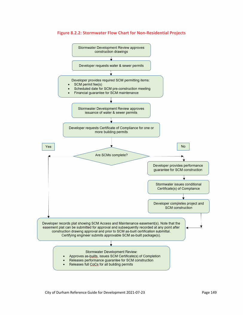
City of Durham Reference Guide for Development 2021‐07‐23 Page 149
Figure 8.2.2: Stormwater Flow Chart for Non‐Residential Projects

City of Durham Reference Guide for Development 2021‐07‐23 Page 150
Figure 8.2.3: Stormwater Flow Chart for Projects with No Building Permits or Water & Sewer
Permits2
2 A project that does not need building permits or water & sewer permits could potentially be a residential or non-residential project.
City of Durham Reference Guide for Development 2021‐07‐23 Page 151
2. End of SCM Permitting Process
The SCM permitting process ends when Stormwater Development Review has approved the as-built certification package and has issued Certificates of Completion for all project SCMs.
At this point, Stormwater Development Review will release all SCM performance guarantees for SCM construction, will remove any stormwater conditions attached to the project, and sign off for stormwater on CoCs for all building permits on the property associated with the SCM(s).
From this point forward, the SCM is now considered to be subject to the City’s SCM maintenance program. When the Certificate of Completion is issued for an SCM, an anniversary month for annual inspection will be assigned. Every year, the owner is responsible for having the SCM inspected by an SCM Maintenance Certifier and the inspection report submitted by the end of the SCM’s anniversary month.
For residential or mixed-use developments where an owner’s association will be responsible or integral for maintaining the SCM, an SCM hand-off meeting is recommended at this point. An SCM hand-off meeting is a meeting of the development’s owners’ association (usually the homeowners association), the developer, and city staff. The purpose of this meeting is to provide a smooth transfer of SCMs from the developer to the association, and to provide an opportunity for the association to better understand their obligations, the developer’s responsibilities, and City requirements. To set up this meeting, contact the Stormwater Development Review engineer who approved the SCM as-built package or send a request to [email protected].
C. SCM Permitting Items
1. Required Items
The required items for each project that has an SCM are described below. The point in the development process at which these items are required is discussed in the following section.
SCM permit fees: Per the current Fee Schedule for the City of Durham (see https://durhamnc.gov/DocumentCenter/View/30850/Fee-Schedule-PDF---revised-May-29-2020), the SCM permit fees are as follows:
o $800 for level spreaders, plus a 4% technology surcharge fee
o $3,700.00 for all other SCMs, plus a 4% technology surcharge fee.
o These fees may be paid by a cash or check payment made payable to the City of Durham. They may be submitted at the Public Works Service Desk on the third floor of City Hall (when City Hall is not closed or partially closed due to COVID-19), or mailed to: City of Durham, Department of Public Works ATTN: Rhonda Spivey 101 City Hall Plaza Durham, NC 27701
Note: See sub-section C.3. below.
o In the following situations, the developer will need to pay the current full SCM permit fee even if an SCM permit fee was previously paid:

City of Durham Reference Guide for Development 2021‐07‐23 Page 152
A new site plan and new construction drawings are submitted for an existing SCM that is being modified and thus needs re-review (for example, to ensure it can handle additional development, an altered drainage area, etc.)
Construction drawings are submitted for an SCM retrofit.
Scheduled SCM pre-construction meeting date: To schedule this meeting, e-mail the Stormwater Development Review SCM Technician at [email protected] a minimum of three business days prior to the desired meeting date. See Section 8.6.1 for further information.
Declaration of Covenants, Conditions, and Restrictions (CC&Rs) (applicable only to residential developments with an owners’ association, including condominiums and mixed use): A copy of the CC&Rs for residential developments with an owners’ association must be emailed to [email protected] for review and approval when the initial plat is submitted through the Development Services Center. See Section 8.2.1 above – all CC&Rs must meet the requirements in that section.
Financial guarantee for SCM maintenance: City Code Section 70-742(c)(5) requires the “Provision of financial guarantees to ensure the long-term maintenance, inspection, repair, and reconstruction of stormwater control measures in accordance with City Code Section 70-751, the Unified Development Ordinance, and City Stormwater Standards.” Residential and mixed-use projects must utilize the City’s Stormwater Facility Replacement Fund. Non-residential projects have an additional option to utilize the Stormwater Facility Replacement Fund.
o Stormwater Facility Replacement Fund Payment: The Stormwater Facility Replacement Fund was created and is maintained in order to receive payments that guarantee perpetual maintenance, repair, and reconstruction of stormwater facilities by persons/entities that are not the City. This payment is non-refundable. If all conditions in City Code Section 70-752 are met, a person/entity paying into the Stormwater Facility Replacement Fund may apply for loans for design, engineering, and reconstruction costs for the SCM for which the payment was made. The Stormwater Facility Replacement Fund Payment will be calculated to be 25% of the Engineer’s Cost Estimate for SCM construction and must be submitted as a cash or check payment made payable to the City of Durham.
o Alternate Security: For non-residential projects, an alternate security calculated at 20 times the average annual maintenance cost of the SCM may be accepted. The maintenance cost of the typical SCM is determined using the spreadsheet Annualized Maintenance Costs for BMPs Spreadsheet. Note: Owners who select this option are not eligible for loans from the Stormwater Facility Replacement Fund.
o Projects by Government Agencies: Projects undertaken by entities such as the City of Durham, Durham County, Durham Public Schools, the State of North Carolina, and the federal government are exempt from the requirement to provide a financial guarantee for SCM maintenance. They are assumed to have sufficient public monies in their budget for facilities maintenance.
Performance guarantee for SCM construction: This security instrument is required if the developer wants to move the project past a certain point in the development process (see next section), and one or more of the permitted SCMs have not been completed. In such a case, the owner must provide the following:
o An acceptable security instrument of 125% of the reasonably estimated cost of SCM completion (based on the approved Engineer’s Cost Estimate) +
o 0.2% construction security management fee +
o 4% technology surcharge based on the construction security management fee.

City of Durham Reference Guide for Development 2021‐07‐23 Page 153
2. Obtaining SCM Permitting Items
Projects that do not have building permits and do not need water and sewer permits: An example of this type of project is a parking lot project. For this type of project, the applicable stormwater permitting items (SCM permit fee, scheduled pre-construction date, and financial guarantee for SCM maintenance) are due prior to Stormwater Development Review signature of the City approval stamp on the Construction Drawings.
Residential projects: Due to the provisions of NC Session Law 2015-187, House Bill 721, and other subsequent revisions to General Statute 160A, the applicable stormwater permitting items are due prior to final plat approval by Stormwater Development Review.
o Before Stormwater Development Review will approve a final plat or condo plat for a residential development, the following are required:
The SCM permit fee(s),
A scheduled SCM pre-construction meeting date,
Owner’s association incorporation with the Secretary of State and the Declaration of CC&Rs,
A financial guarantee for SCM maintenance, and
A performance guarantee for SCM construction if the SCMs are not complete and an approvable SCM as-built package(s) has not been submitted.
o Once these conditions are met, the final plat will be approved and no project building permits or CoCs will be withheld by Stormwater Development Review. Note that building permits and CoCs can and will be withheld should the City reasonably determine the existence of a public safety issue. This would happen should inadequate progress on SCM completion occur or the developer fails to submit the geotechnical certification for the SCM dam construction within 30 days of completion in accordance with Section 8.6.4 of this document. Inadequate progress is when reasonable, good faith progress toward completion is not being demonstrated and failure to move the SCM toward completion unnecessarily delays the complete functionality of the stormwater facility, which is to mitigate increased runoff and remove pollutants from the stormwater generated by the development. Such inactions can: degrade stream buffers, stream channels, and surface waters; lead to flooding; and cause downstream erosion, as well as other adverse impacts.
All other projects, except mixed-use projects: For projects that do not fall into the first two categories above, all stormwater permitting items except the performance guarantee for SCM construction must be submitted prior to issuance of water and sewer permits. When there are no further comments on the CDs, Stormwater Development Review will sign the City approval stamp on the CDs and will issue a letter stating that prior to the issuance of water & sewer permits, the applicable SCM permitting items must be provided. In this case, the financial guarantee for SCM maintenance may take the form either of a payment into the City’s Stormwater Facility Replacement Fund or an alternate security in the amount of 20 times the annual maintenance cost of the SCM. To obtain a partial occupancy, conditional certificate of compliance, or certificates of compliance (CoC) for a building within the project, all project SCMs should be completed and the as-built certifications for the SCMs should be approved by Stormwater Development Review. If, however, a CoC is requested and one or more of the permitted SCMs have not been completed, a partial occupancy or conditional CoC will be issued upon the owner's provision of a performance guarantee for SCM construction.
City of Durham Reference Guide for Development 2021‐07‐23 Page 154
Mixed-use projects: For these projects, the first of the following process milestones to be reached will be used as the trigger to require all SCM permitting items except the performance guarantee for SCM construction:
o Final plat approval, or
o Issuance of water and sewer permits.
The first of the following process milestones to be reached will trigger the need for the performance guarantee for SCM construction:
o Final plat approval, or
o Request for a partial occupancy, conditional CoC, or CoC.
3. Payment of Fees
The SCM permit fee, the technology surcharge, and the construction management fee may be paid in cash or by check made payable to the City of Durham.
For performance guarantees for SCM construction, the 0.2% construction security management fee is based on the amount of the performance guarantee for SCM construction, and the 4% technology surcharge is calculated based on the construction security management fee.
These fees may be submitted at the Public Works Service Desk on the third floor of City Hall (when City Hall is not closed due to COVID-19), or mailed* to: City of Durham, Department of Public Works ATTN: Rhonda Spivey 101 City Hall Plaza Durham, NC 27701
*When mailing or sending checks via courier, the City also requires a copy of the check to be emailed to [email protected]. This helps the City know what is incoming and facilitates payment, receipt issuance, and release of holds on needed items in the timeliest manner.
4. Paperwork for Sureties
For each of the acceptable security instruments, the developer will need to fill out the associated form and submit it with the security. The forms are as follows:
o For an Irrevocable Letter of Credit: ”IRREVOCABLE LETTER OF CREDIT” form.
o For an Assignable Certificate of Deposit: “ASSIGNMENT OF CERTIFICATE OF DEPOSIT AND ACKNOWLEDGMENT BY BANK” form.
o A Bank Cashier's Check: An “ESCROW AGREEMENT” using the City’s standard template must be executed by the owner.
o A Performance Bond: “STORMWATER FACILITY BOND” form.
To obtain the relevant form and further guidance, e-mail [email protected]. The forms can also be found on the City’s website at https://durhamnc.gov/2988/Forms-and-Templates.
City of Durham Reference Guide for Development 2021‐07‐23 Page 155
5. Time Limits for SCM Completion Securities
The expected length of time for developers to complete SCMs is shown below and depends upon the project type:
For residential and mixed use developments: 2.5 years
For non-residential developments: 1 year
When the end of this time period approaches, Stormwater Development Review will begin reminding the developer that the SCMs are due to be completed. If the SCMs are not completed within the expected time frame and good faith efforts toward completion are not being witnessed, this shall be considered a violation and remedies available in City Code Section 70-744 may be exercised as well as the City may demand payment of the performance guarantee for SCM construction. The developer and/or SCM construction contractor should be fulfilling their communication obligations in accordance with Section 8.6, thus any reminders received should not come as a surprise.
City of Durham Reference Guide for Development 2021‐07‐23 Page 156
Section 8.3: Stormwater Control Measures
8.3.1 General
The City of Durham recognizes the importance of controlling stormwater, both quality and quantity to preserve the City’s natural resources, public safety and the overall well-being of the citizens of Durham. The techniques developed to improve stormwater quality and quantity are referred to most commonly as “Best Management Practices” (BMPs). This section covers structural BMPs or Stormwater Control Measures (SCMs), as the City of Durham generally refers to them as. SCMs are complex structures that must be designed and constructed with the specific site conditions, the availability of construction materials, the particular functions of the facility, and the associated hazards in mind. The City recognizes that the most effective control of stormwater pollutants is to reduce their generation at the source. The guidelines and standards provided herein, when applied correctly, will reduce the concerns with stormwater runoff, thus protecting the safety, health and general welfare of the public. The design of an SCM requires considerable engineering judgment and experience and no single written document, including but not limited to this document, can cover all the design and construction issues that may be confronted by the design engineer. It should be noted that the SCM design requirements referenced in this document are minimum design requirements based on typical conditions and, as such, are not meant to be considered all-inclusive for the design of any particular SCM. It shall also be noted that in order to most effectively treat stormwater for a given site, it is necessary for the designer to determine which type of SCM(s) are most appropriate for the physical characteristics of the site as well as the intended usages of the site. Physical site constraints may include soil suitability, depth to the seasonally high water table, depth to bedrock, slope, and watershed size. Site usage and other constraints may include proximity to potable water sources, foundations, land availability and cost, recreational use potential, aquatic and terrestrial wildlife habitat values, and maintenance requirements.
The acceptability of the design and the adequacy of the plans and specifications for the SCMs will be determined by these guidelines/standards. Ultimately, the responsibility for the proper design of the stormwater facility and its appurtenant structures shall rest with the design engineer of record and not with the City of Durham (City). When approving construction drawings, the City takes into consideration the fact that the plans and specifications were prepared, sealed, signed, and dated by a Professional Engineer licensed to practice engineering in the State of North Carolina and that the design engineer of record is wholly and solely responsible for the content of the plans and specifications.
In instances where any State or Federal statute, requirement, or standard is more or less stringent than that required by the City, the more stringent statute, requirement, or standard shall apply. When determined that a dam is subject to the Dam Safety Law of 1967 (15A NCAC 02K .0201), approval of the dam design by the North Carolina Dam Safety Office will be required prior to City approval of the plans. Additionally, where other state and/or federal approvals or permits are required, said approvals and permits shall be obtained and the City may utilize its discretion whether to review or approve plans prior to obtaining. It is the owner’s/applicant’s responsibility to ensure all state and federal regulations are complied with. It should be recognized that stormwater quality technology, design criteria, and requirements, as well as federal, state, laws and regulations, are dynamic and periodically change. As such the City expects the designer to stay current with these latest requirements, since this manual is only periodically updated.
The future operation and maintenance of SCMs is a primary concern to the City. Engineers, in the preparation of Construction Drawings, must include facility maintenance and operation as a primary design consideration.
City of Durham Reference Guide for Development 2021‐07‐23 Page 157
Design elements not covered in this section are not necessarily allowed or disallowed. The merits and efficacy of such elements submitted for approval by an NCPE working in an area of competency will be subject to the review of City staff based upon accepted engineering practices.
A. Design Documents
1. The design of each SCM device shall be displayed on a plan sheet dedicated solely to providing detailed design views of the device. For review and future archiving purposes, the plan view of the facility shall be at a scale of 1 inch = 30 feet or larger, and the scaled profile view of the dam (if present), emergency spillway, and outlet works shall be at a horizontal scale of 1 inch = 10 feet or larger and at a vertical scale of 1 inch = 5 feet or larger.
2. For underground and filtration systems, the scaled profile shall include the impoundment/storage structures and the inlet/s to the device.
3. Seasonal high water table (SHWT) levels or perched water tables due to confining soil layers shall be depicted on the profile view of all proposed SCM structures (including Filterra® units, underground sand filters, and below grade rainwater harvesting systems). The location of each test should be within the footprint of the proposed SCM in question; however, adjacent borings in close proximity to the facility and with like topographical conditions can be accepted by the City.
4. Hydraulic inputs and performance tables for each device shall be included with each construction drawing submittal package. In addition, all routing inputs and outputs for the operation of the facility, and all documentation showing how these inputs and outputs were determined shall be provided with the submittal package.
B. Design Methodologies
To regulate stormwater control measure design and construction, the City of Durham utilizes the following:
The archived North Carolina Division of Environmental Quality Stormwater Best Management Practices Manual 2009-2016 and its associated SCM Manual Errata Sheet. These documents can be viewed or downloaded from the Division of Environmental Quality’s website at the following address: https://deq.nc.gov/about/divisions/energy-mineral-land-resources/energy-mineral-land-permit-guidance/stormwater-bmp-manual/archive.
The City of Durham Addendum to the state manual, which can be found under the City’s Stormwater Development Review webpage at: http://durhamnc.gov/DocumentCenter/View/3082/City-of-Durham-Addendum-to-the-NC-DWQ-Stormwater-Best-Management-Practices-Manual-PDF?bidId=.
Please note that additional chapters have been added to the Stormwater Best Management Practices Manual through the City of Durham Addendum. These chapters are inserted after the appendix.
*Revised July 1, 2018

City of Durham Reference Guide for Development 2021‐07‐23 Page 158
Section 8.4: Stormwater SCM Design Summaries
Fillable PDF files can be found at http://durhamnc.gov/2988/Forms-and-Templates.
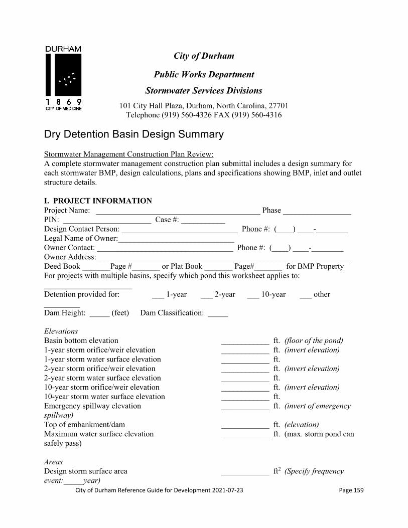
City of Durham Reference Guide for Development 2021‐07‐23 Page 159
City of Durham
Public Works Department
Stormwater Services Divisions
101 City Hall Plaza, Durham, North Carolina, 27701 Telephone (919) 560-4326 FAX (919) 560-4316
Dry Detention Basin Design Summary Stormwater Management Construction Plan Review: A complete stormwater management construction plan submittal includes a design summary for each stormwater BMP, design calculations, plans and specifications showing BMP, inlet and outlet structure details. I. PROJECT INFORMATION Project Name: _________________________________________ Phase _________________ PIN: ______________________ Case #: ___________ Design Contact Person: _____________________________ Phone #: (____) ____-________ Legal Name of Owner:_____________________________ Owner Contact: __________________________________ Phone #: (____) ____-________ Owner Address:________________________________________________________________ Deed Book _______Page #_______ or Plat Book _______ Page#_______ for BMP Property For projects with multiple basins, specify which pond this worksheet applies to: ______________________ Detention provided for: ___ 1-year ___ 2-year ___ 10-year ___ other _________ Dam Height: _____ (feet) Dam Classification: _____ Elevations Basin bottom elevation ____________ ft. (floor of the pond) 1-year storm orifice/weir elevation ____________ ft. (invert elevation) 1-year storm water surface elevation ____________ ft. 2-year storm orifice/weir elevation ____________ ft. (invert elevation) 2-year storm water surface elevation ____________ ft. 10-year storm orifice/weir elevation ____________ ft. (invert elevation) 10-year storm water surface elevation ____________ ft. Emergency spillway elevation ____________ ft. (invert of emergency spillway) Top of embankment/dam ____________ ft. (elevation) Maximum water surface elevation ____________ ft. (max. storm pond can safely pass) Areas Design storm surface area ____________ ft2 (Specify frequency event:_____year)
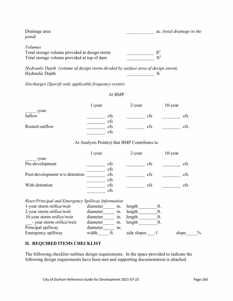
City of Durham Reference Guide for Development 2021‐07‐23 Page 160
Drainage area ____________ ac. (total drainage to the pond) Volumes Total storage volume provided at design storm ____________ ft3 Total storage volume provided at top of dam ____________ ft3 Hydraulic Depth (volume of design storm divided by surface area of design storm) Hydraulic Depth ____________ ft. Discharges (Specify only applicable frequency events)
At BMP 1-year 2-year 10-year _____-year Inflow ________ cfs ________ cfs ________ cfs ________ cfs Routed outflow ________ cfs ________ cfs ________ cfs ________ cfs
At Analysis Point(s) that BMP Contributes to 1-year 2-year 10-year _____-year Pre-development ________ cfs ________ cfs ________ cfs ________ cfs Post-development w/o detention ________ cfs ________ cfs ________ cfs ________ cfs With detention ________ cfs ________ cfs ________ cfs ________ cfs Riser/Principal and Emergency Spillway Information 1-year storm orifice/weir diameter_____ in. length ________ft. 2-year storm orifice/weir diameter_____ in. length ________ft. 10-year storm orifice/weir diameter_____ in. length ________ft. ___- year storm orifice/weir diameter_____ in. length ________ft. Principal spillway diameter_____ in. Emergency spillway width_____ ft. side slopes ___:1 slope_____% II. REQUIRED ITEMS CHECKLIST The following checklist outlines design requirements. In the space provided to indicate the following design requirements have been met and supporting documentation is attached.

City of Durham Reference Guide for Development 2021‐07‐23 Page 161
Applicant’s initials ____________ a. Riprap outlet protection, if provided, reduces flow to non-erosive velocities
(provide calculations). ____________ b. The basin side slopes are no steeper than 3:1. ____________ c. Vegetative cover for the basin is specified. No woody vegetation is permitted on
the embankment. ____________ d. A trash rack or similar device is provided for both the overflow and orifice.
Flat top trash racks are not acceptable. Access hatch has been provided. ____________ e. A recorded drainage easement is provided for each basin including access to the
nearest right-of-way and is graded per Section 8.3, Stormwater Control Facilities (BMPs).
____________ f. If the basin is used for sediment and erosion control during construction, a note requiring clean out and vegetative cover being established prior to use as a dry detention basin shall be provided on the construction plan.
____________ g. Anti-floatation calculations are provided for riser structure. ____________ h. A plan view of the pond with grading shown is provided. ____________ i. A profile through the forebay, main pond and spillway is provided. Water
surface elevations are shown on the profile. ____________ j. Riser structure details are provided. ____________ k. Compaction specifications for the embankment are provided on the plan. ____________ l. Dam designed to account for a 5.00% settlement factor. ____________ m. The minimum top of dam width has been provided for the pond embankment
top width per Section 8.3, Stormwater Control Facilities (BMPs). Note: Executed Stormwater Facility Operation and Maintenance Permit Agreement, payment of permit fee per facility and payment of surety are required prior to construction drawing approval.

City of Durham Reference Guide for Development 2021‐07‐23 Page 162
City of Durham
Public Works Department
Stormwater Services Divisions
101 City Hall Plaza, Durham, North Carolina, 27701 Telephone (919) 560-4326 FAX (919) 560-4316
Wet Detention Pond Design Summary Stormwater Management Construction Plan Review: A complete stormwater management construction plan submittal includes a design summary for each stormwater BMP, design calculations, plans and specifications showing BMP, inlet and outlet structure details. I. PROJECT INFORMATION Project Name: _________________________________________ Phase _________________ PIN: ______________________ Case #: ___________ Design Contact Person: _____________________________ Phone #: (____) ____-________ Legal Name of Owner:_____________________________ Owner Contact: __________________________________ Phone #: (____) ____-________ Owner Address:________________________________________________________________ Deed Book _______Page #_______ or Plat Book _______ Page#_______ for BMP Property For projects with multiple basins, specify which pond this worksheet applies to: ___________________ Does the proposed pond also incorporate stormwater detention? Yes No Detention provided for: ___ 1-year ___ 2-year ___ 10-year ___ other _________ Dam Height: _____ (feet) Dam Classification: _____ Elevations Pond bottom elevation ____________ ft. (floor of the pond) Permanent pool elevation ____________ ft. (invert elevation of the orifice) Temporary pool elevation ____________ ft. (elevation of the structure overflow) 1-year storm orifice/weir elevation ____________ ft. (invert elevation) 1-year storm water surface elevation ____________ ft. 2-year storm orifice/weir elevation ____________ ft. (invert elevation) 2-year storm water surface elevation ____________ ft. 10-year storm orifice/weir elevation ____________ ft. (invert elevation) 10-year storm water surface elev. ____________ ft. Emergency spillway elevation ____________ ft. (invert of emergency spillway) Top of embankment/dam ____________ ft. (elevation)

City of Durham Reference Guide for Development 2021‐07‐23 Page 163
Maximum water surface elevation ____________ ft. (max. storm pond can safely pass) Areas Permanent pool area provided ____________ ft2 (water surface area at orifice invert elevation) Minimum required permanent pool area ____________ ft2 (calculated surface area required) Design storm surface area ____________ ft2 (Specify frequency event:_____ year) Drainage area (10-acres min) ____________ ac. (total drainage to the pond Discharges (Specify only applicable frequency events)
At BMP 1-year 2-year 10-year _____-year Inflow ________ cfs ________ cfs ________ cfs ________ cfs Routed outflow ________ cfs ________ cfs ________ cfs ________ cfs
At Analysis Point(s) that BMP Contributes to 1-year 2-year 10-year _____-year Pre-development ________ cfs ________ cfs ________ cfs ________ cfs Post-development w/o detention ________ cfs ________ cfs ________ cfs ________ cfs With detention ________ cfs ________ cfs ________ cfs ________ cfs Volumes Permanent pool volume ____________ ft3 (volume of main pond and forebay) Water quality pool storage volume ____________ ft3 (volume above permanent pool) Design storm storage volume ____________ ft3 (volume above permanent pool) Total Storage volume provided at design storm ____________ ft3 Total Storage volume provided at top of dam ____________ ft3
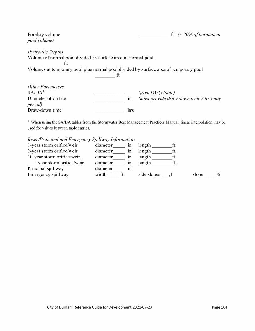
City of Durham Reference Guide for Development 2021‐07‐23 Page 164
Forebay volume ____________ ft3 (~ 20% of permanent pool volume) Hydraulic Depths Volume of normal pool divided by surface area of normal pool ________ ft. Volumes at temporary pool plus normal pool divided by surface area of temporary pool ________ ft. Other Parameters SA/DA1 ____________ (from DWQ table) Diameter of orifice ____________ in. (must provide draw down over 2 to 5 day period) Draw-down time ____________ hrs 1 When using the SA/DA tables from the Stormwater Best Management Practices Manual, linear interpolation may be
used for values between table entries. Riser/Principal and Emergency Spillway Information 1-year storm orifice/weir diameter_____ in. length ________ft. 2-year storm orifice/weir diameter_____ in. length ________ft. 10-year storm orifice/weir diameter_____ in. length ________ft. ___- year storm orifice/weir diameter_____ in. length ________ft. Principal spillway diameter_____ in. Emergency spillway width_____ ft. side slopes ___:1 slope_____%
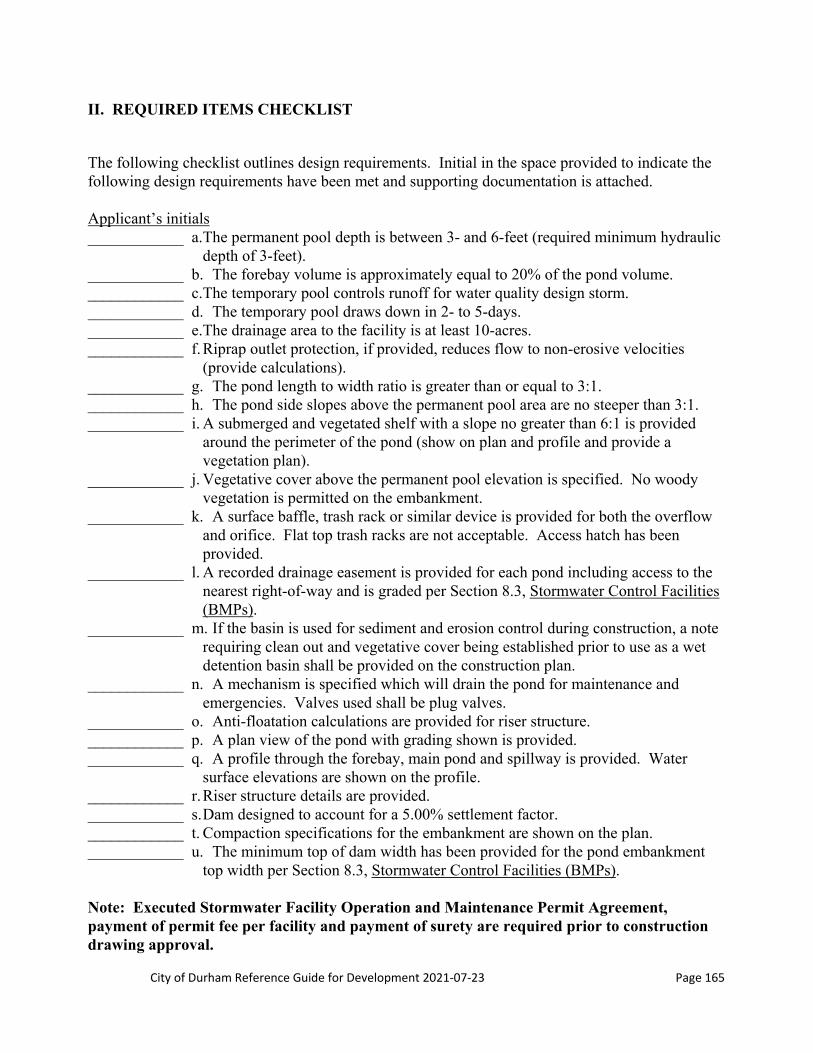
City of Durham Reference Guide for Development 2021‐07‐23 Page 165
II. REQUIRED ITEMS CHECKLIST
The following checklist outlines design requirements. Initial in the space provided to indicate the following design requirements have been met and supporting documentation is attached. Applicant’s initials ____________ a. The permanent pool depth is between 3- and 6-feet (required minimum hydraulic
depth of 3-feet). ____________ b. The forebay volume is approximately equal to 20% of the pond volume. ____________ c. The temporary pool controls runoff for water quality design storm. ____________ d. The temporary pool draws down in 2- to 5-days. ____________ e. The drainage area to the facility is at least 10-acres. ____________ f. Riprap outlet protection, if provided, reduces flow to non-erosive velocities
(provide calculations). ____________ g. The pond length to width ratio is greater than or equal to 3:1. ____________ h. The pond side slopes above the permanent pool area are no steeper than 3:1. ____________ i. A submerged and vegetated shelf with a slope no greater than 6:1 is provided
around the perimeter of the pond (show on plan and profile and provide a vegetation plan).
____________ j. Vegetative cover above the permanent pool elevation is specified. No woody vegetation is permitted on the embankment.
____________ k. A surface baffle, trash rack or similar device is provided for both the overflow and orifice. Flat top trash racks are not acceptable. Access hatch has been provided.
____________ l. A recorded drainage easement is provided for each pond including access to the nearest right-of-way and is graded per Section 8.3, Stormwater Control Facilities (BMPs).
____________ m. If the basin is used for sediment and erosion control during construction, a note requiring clean out and vegetative cover being established prior to use as a wet detention basin shall be provided on the construction plan.
____________ n. A mechanism is specified which will drain the pond for maintenance and emergencies. Valves used shall be plug valves.
____________ o. Anti-floatation calculations are provided for riser structure. ____________ p. A plan view of the pond with grading shown is provided. ____________ q. A profile through the forebay, main pond and spillway is provided. Water
surface elevations are shown on the profile. ____________ r. Riser structure details are provided. ____________ s. Dam designed to account for a 5.00% settlement factor. ____________ t. Compaction specifications for the embankment are shown on the plan. ____________ u. The minimum top of dam width has been provided for the pond embankment
top width per Section 8.3, Stormwater Control Facilities (BMPs). Note: Executed Stormwater Facility Operation and Maintenance Permit Agreement, payment of permit fee per facility and payment of surety are required prior to construction drawing approval.

City of Durham Reference Guide for Development 2021‐07‐23 Page 166
City of Durham
Public Works Department
Stormwater Services Divisions
101 City Hall Plaza, Durham, North Carolina, 27701 Telephone (919) 560-4326 FAX (919) 560-4316
Sand Filter Design Summary Stormwater Management Construction Plan Review: A complete stormwater management construction plan submittal includes a design summary for each stormwater BMP, design calculations, plans and specifications showing BMP, inlet and outlet structure details. I. PROJECT INFORMATION Project Name: _________________________________________ Phase _________________ PIN: ______________________ Case #: ___________ Design Contact Person: _____________________________ Phone #: (____) ____-________ Legal Name of Owner:_____________________________ Owner Contact: __________________________________ Phone #: (____) ____-________ Owner Address:________________________________________________________________ Deed Book _______Page #_______ or Plat Book _______ Page#_______ for BMP Property For projects with multiple basins, specify which pond this worksheet applies to: ___________________ Drainage area ____________ ac. (total drainage area to the sand filter) Impervious area ____________ ac. (total impervious area to the sand filter) Design runoff ____________ in. Design treatment volume (540 ft3/Ac) ____________ ft3 Sediment chamber design Bottom elevation ____________ ft. (floor of the sediment chamber) Weir elevation ____________ ft. (invert elevation of overflow to sand bed) Volume ____________ ft3 (volume of sediment chamber to weir elevation) Surface area ____________ ft2 (surface area of sediment chamber at bottom) Design treatment volume provided ____________ ft3 Sand filter bed design

City of Durham Reference Guide for Development 2021‐07‐23 Page 167
Bottom elevation ____________ ft. (elevation of bottom of sand bed) Top of sand ____________ ft. (elevation of top of sand) Sand volume ____________ ft3 (volume of sand in bed) Sand surface area ____________ ft2 (surface area of sand bed at bottom of bed) Design treatment volume provided ____________ ft3 Perforated pipe length ____________ ft. (length of perforated pipe provided under sand bed) Diameter of perforated pipe ____________ in. (pipe diameter of perforated pipe) II. REQUIRED ITEMS CHECKLIST The following checklist outlines design requirements. Initial in the space provided to indicate the following design requirements have been met and supporting documentation is attached. Applicant’s initials ____________ a. Runoff from landscaped areas and other non-impervious areas has been directed
away from the sand filter to the maximum extent practical. ____________ b. Drainage area for sand filter is less than 5-acres. ____________ c. Maximum water quality head over the sand filter is 12” or less. ____________ d. Plan specifies how all slopes draining to the sand filter will be stabilized. ____________ e. No side slopes draining to sand filter greater than 3:1. ____________ f. Design drawings provide note: “All slopes draining to sand filter shall be
stabilized per the North Carolina State Erosion and Sediment Control Planning and Design Manual before sand is placed in sand bed.”
____________ g. Riprap outlet protection, if provided, reduces flow to non-erosive velocities (provide calculations).
____________ h. A recorded drainage easement is provided for each sand filter including access to the nearest right-of-way and is graded per Section 8.3, Stormwater Control Facilities (BMPs).
____________ i. Anti-floatation calculations are provided for riser structure. ____________ j. A surface baffle, trash rack or similar device is provided for both the overflow
and orifice. Flat top trash racks are not acceptable. Access hatch has been provided.
____________ k. A plan view of the sand filter with grading shown is provided. ____________ l. A profile through the settling chamber, sand bed and spillway is provided. Water
surface elevations are shown on the profile. ____________ m. Riser structure details are provided. ____________ n. Compaction specifications for the embankment are provided on the plan. ____________ o. Runoff from storms larger than the 1-year storm are routed around the sand bed. ____________ p. Sand size, type and gradation specified. The sand shall be a clean ASTM C-33
medium aggregate sand with a size range of 0.02-inch to 0.04-inch. Note: Executed Stormwater Facility Operation and Maintenance Permit Agreement, payment of permit fee per facility and payment of surety are required prior to construction drawing approval.

City of Durham Reference Guide for Development 2021‐07‐23 Page 168
City of Durham Public Works Department
Stormwater Services Divisions
101 City Hall Plaza, Durham, North Carolina, 27701 Telephone (919) 560-4326 FAX (919) 560-4316
Bio‐Retention Area Design Summary Stormwater Management Construction Plan Review: A complete stormwater management construction plan submittal includes a design summary for each stormwater BMP, design calculations, plans and specifications showing BMP, inlet and outlet structure details. I. PROJECT INFORMATION Project Name: _________________________________________ Phase _________________ PIN: ______________________ Case #: ___________ Design Contact Person: _____________________________ Phone #: (____) ____-________ Legal name of Owner:_____________________________ Owner Contact: __________________________________ Phone #: (____) ____-________ Owner Address:________________________________________________________________ Deed Book _______Page #_______ or Plat Book _______ Page#_______ for BMP Property For projects with multiple basins, specify which pond this worksheet applies to: ___________________ Drainage area ____________ ac (on-site drainage to the area, 1-acre max1) Impervious area ____________ ac (on-site impervious area draining to facility) Design runoff ____________ cfs Design treatment volume ____________ ft3 1 Assumes 100% impervious, larger areas may be considered if maximum sheet flow velocity is not exceeded
Bioretention Design Grass buffer strip width ____________ ft (Max slope of 4:1 and minimum width of 10 feet or a forebay) Size of cell area ____________ ft2 (Min 5% of drainage area with sand bed, 7% without bed) Depth of ponding area ____________ ft (6-inches max) Width of cell ____________ ft (Minimum width of 25-feet2) Length of cell ____________ ft (Minimum length of 2 times the width) Inflow sheet flow velocity ____________ ft/s (Maximum of 1-foot/second) Mulch layer elevation ____________ ft (Elevation of top of layer) Planting soil top elevation ____________ ft (Elevation of top of soil) Depth of planting soil ____________ ft (Minimum depth of 4-feet3) Top of sand if applicable ____________ ft (Elevation of top of sand)
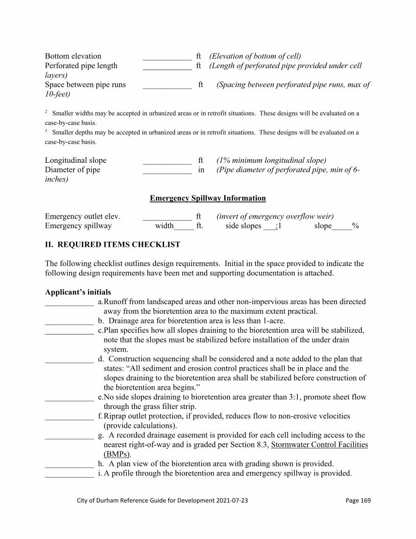
City of Durham Reference Guide for Development 2021‐07‐23 Page 169
Bottom elevation ____________ ft (Elevation of bottom of cell) Perforated pipe length ____________ ft (Length of perforated pipe provided under cell layers) Space between pipe runs ____________ ft (Spacing between perforated pipe runs, max of 10-feet) 2 Smaller widths may be accepted in urbanized areas or in retrofit situations. These designs will be evaluated on a
case-by-case basis. 3 Smaller depths may be accepted in urbanized areas or in retrofit situations. These designs will be evaluated on a
case-by-case basis. Longitudinal slope ____________ ft (1% minimum longitudinal slope) Diameter of pipe ____________ in (Pipe diameter of perforated pipe, min of 6-inches)
Emergency Spillway Information
Emergency outlet elev. ____________ ft (invert of emergency overflow weir) Emergency spillway width_____ ft. side slopes ___:1 slope_____% II. REQUIRED ITEMS CHECKLIST The following checklist outlines design requirements. Initial in the space provided to indicate the following design requirements have been met and supporting documentation is attached. Applicant’s initials ____________ a. Runoff from landscaped areas and other non-impervious areas has been directed
away from the bioretention area to the maximum extent practical. ____________ b. Drainage area for bioretention area is less than 1-acre. ____________ c. Plan specifies how all slopes draining to the bioretention area will be stabilized,
note that the slopes must be stabilized before installation of the under drain system.
____________ d. Construction sequencing shall be considered and a note added to the plan that states: “All sediment and erosion control practices shall be in place and the slopes draining to the bioretention area shall be stabilized before construction of the bioretention area begins.”
____________ e. No side slopes draining to bioretention area greater than 3:1, promote sheet flow through the grass filter strip.
____________ f. Riprap outlet protection, if provided, reduces flow to non-erosive velocities (provide calculations).
____________ g. A recorded drainage easement is provided for each cell including access to the nearest right-of-way and is graded per Section 8.3, Stormwater Control Facilities (BMPs).
____________ h. A plan view of the bioretention area with grading shown is provided. ____________ i. A profile through the bioretention area and emergency spillway is provided.

City of Durham Reference Guide for Development 2021‐07‐23 Page 170
____________ j. Geotextile fabric is placed at the bottom of the excavated cell to prevent soil from getting into the underdrain system.
____________ k. The underdrain system is wrapped in a gravel jacket and a geotextile fabric is placed between the bottom of the sand bed or planting soil and the top of the gravel jacket.
____________ l. The pipe for the underdrain system shall be perforated Schedule 40 PVC. ____________ m. The underdrain system shall connect to the outflow system at a point at least 1
foot inside the bioretention cell wall. ____________ n. A non-perforated piping system is connected to the underdrain piping and
extends to the surface of the planting soil for cleanouts. ____________ o. Cleanouts are to be provided at the beginning of each pipe run and at all
intersections. ____________ p. A planting soil mixture specification and a soil characteristics table are
provided. Maximum clay content in the soil mixture is 8.00%. ____________ q. The hydraulic conductivity for the planting mixture is to be 1-inch to 2-inches
per hour. ____________ r. Mulch layer specification is provided; mulch is to be a 4-inch layer of coarse
hardwood mulch with re-application rate specified. ____________ s. Soil with a P index of less than or equal to 25 specified on plan. ____________ t. A bioretention area landscape plan is provided including the transport of plant
material, preparation of the planting pit, fertilization, installation of the plant material, type and number of plantings (note that there shall be a minimum of three species of trees and three species of shrubs selected to insure diversity, their planting locations, post-installation inspection and maintenance guidelines.
Note: Executed Stormwater Facility Operation and Maintenance Permit Agreement, payment of permit fee per facility and payment of surety are required prior to construction drawing approval.

City of Durham Reference Guide for Development 2021‐07‐23 Page 171
City of Durham
Public Works Department
Stormwater Services Divisions
101 City Hall Plaza, Durham, North Carolina, 27701 Telephone (919) 560-4326 FAX (919) 560-4316
Constructed Wetland and Pocket Wetland Design Summary Stormwater Management Construction Plan Review: A complete stormwater management construction plan submittal includes a design summary for each stormwater BMP, design calculations, plans and specifications showing BMP, inlet and outlet structure details. I. PROJECT INFORMATION Project Name: _________________________________________ Phase _________________ PIN: ______________________ Case #: ___________ Design Contact Person: _____________________________ Phone #: (____) ____-________ Legal Name of Owner:_____________________________ Owner Contact: __________________________________ Phone #: (____) ____-________ Owner Address:________________________________________________________________ Deed Book _______Page #_______ or Plat Book _______ Page#_______ for BMP Property For projects with multiple basins, specify which pond this worksheet applies to: ___________________ Does the proposed pond also incorporate stormwater detention? Yes No Detention provided for: ___ 1-year ___ 2-year ___ 10-year ___ other _________ Dam Height: _____ (feet) Dam Classification: _____ Elevations Wetland bottom elevation ____________ ft. (floor of the wetland) Permanent pool elevation ____________ ft. (invert elevation of the orifice) Temporary pool elevation ____________ ft. (elevation of the structure overflow) 1-year storm orifice/weir elevation ____________ ft. (invert elevation) 1-year storm water surface elevation ____________ ft. 2-year storm orifice/weir elevation ____________ ft. (invert elevation) 2-year storm water surface elevation ____________ ft. 10-year storm orifice/weir elevation ____________ ft. (invert elevation) 10-year storm water surface elev. ____________ ft. Emergency spillway elevation ____________ ft. (invert of emergency spillway)
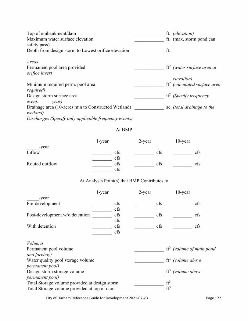
City of Durham Reference Guide for Development 2021‐07‐23 Page 172
Top of embankment/dam ____________ ft. (elevation) Maximum water surface elevation ____________ ft. (max. storm pond can safely pass) Depth from design storm to Lowest orifice elevation ____________ ft. Areas Permanent pool area provided ____________ ft2 (water surface area at orifice invert elevation) Minimum required perm. pool area ____________ ft2 (calculated surface area required) Design storm surface area ____________ ft2 (Specify frequency event:_____ year) Drainage area (10-acres min to Constructed Wetland) ____________ ac. (total drainage to the wetland) Discharges (Specify only applicable frequency events)
At BMP 1-year 2-year 10-year _____-year Inflow ________ cfs ________ cfs ________ cfs ________ cfs Routed outflow ________ cfs ________ cfs ________ cfs ________ cfs
At Analysis Point(s) that BMP Contributes to 1-year 2-year 10-year _____-year Pre-development ________ cfs ________ cfs ________ cfs ________ cfs Post-development w/o detention ________ cfs ________ cfs ________ cfs ________ cfs With detention ________ cfs ________ cfs ________ cfs ________ cfs Volumes Permanent pool volume ____________ ft3 (volume of main pond and forebay) Water quality pool storage volume ____________ ft3 (volume above permanent pool) Design storm storage volume ____________ ft3 (volume above permanent pool) Total Storage volume provided at design storm ____________ ft3 Total Storage volume provided at top of dam ____________ ft3

City of Durham Reference Guide for Development 2021‐07‐23 Page 173
Forebay volume (Constructed Wetlands only) ____________ ft3
Environmental Zones
Zone Water Depth at Normal Pool1
Water Depth at Temporary Pool
(Max Depth of 12-inches above Normal
Pool)1
Portion of Temporary Pool
Surface Area
Deep Pool
Low Marsh
High Marsh
Woody Upland
1 Depths are to be calculated using the hydraulic depth calculation for each zone. Hydraulic Depth is the volume of
water at an elevation divided by the water surface area at the same elevation.
Other Parameters SA/DA2 ____________ (from DWQ table) Diameter of orifice ____________ in. (must provide draw down over 2 to 5 day period) Draw-down time ____________ hrs Design TSS removal ____________ % (minimum 85% removal required) 2 When using the SA/DA tables from the NCDENR BMP Manual, linear interpolation may be used for values between
table entries.)
Riser/Principal and Emergency Spillway Information 1-year storm orifice/weir diameter_____ in. length ________ft. 2-year storm orifice/weir diameter_____ in. length ________ft. 10-year storm orifice/weir diameter_____ in. length ________ft. ___- year storm orifice/weir diameter_____ in. length ________ft. Principal spillway diameter_____ in. Emergency spillway width_____ ft. side slopes ___:1 slope_____% II. REQUIRED ITEMS CHECKLIST The following checklist outlines design requirements. Initial in the space provided to indicate the following design requirements have been met and supporting documentation is attached.

City of Durham Reference Guide for Development 2021‐07‐23 Page 174
Applicant’s initials ____________ a. The forebay volume is approximately equal to 20% of the pond volume. ____________ b. The temporary pool controls runoff for water quality design storm. ____________ c. The temporary pool draws down in 2- to 5-days. ____________ d. Riprap outlet protection, if provided, reduces flow to non-erosive velocities
(provide calculations). ____________ e. The wetland length to width ratio is greater than or equal to 3:1. ____________ f. The wetland side slopes above the permanent pool area are no steeper than 3:1. ____________ g. A submerged and vegetated shelf with a slope no greater than 6:1 is provided
around the perimeter of the pond (show on plan and profile and provide a vegetation plan).
____________ h. Vegetative cover above the permanent pool elevation is specified. No woody vegetation is permitted on the embankment.
____________ i. A surface baffle, trash rack or similar device is provided for both the overflow and orifice. Flat top trash racks are not acceptable. Access hatch has been provided.
____________ j. A recorded drainage easement is provided for each pond including access to the nearest right-of-way and is graded per Section 8.3, Stormwater Control Facilities (BMPs).
____________ k. If the basin is used for sediment and erosion control during construction, a note requiring clean out and vegetative cover being established prior to use as a wet detention basin shall be provided on the construction plan.
____________ l. A mechanism is specified which will drain the pond for maintenance and emergencies. Valves used shall be plug valves.
____________ m. Anti-floatation calculations are provided for riser structure. ____________ n. A plan view of the wetland with grading shown is provided. ____________ o. A profile through the forebay, wetland and spillway is provided. Water surface
elevations are shown on the profile. ____________ p. Riser structure details are provided. ____________ q. Dam designed to account for a 5.00% settlement factor. ____________ r. Compaction specifications for the embankment are shown on the plan. ____________ s. The minimum top of dam width has been provided for the wetland embankment
top width per Section 8.3, Stormwater Control Facilities (BMPs) Note: Executed Stormwater Facility Operation and Maintenance Permit Agreement, payment of permit fee per facility and payment of surety are required prior to construction drawing approval
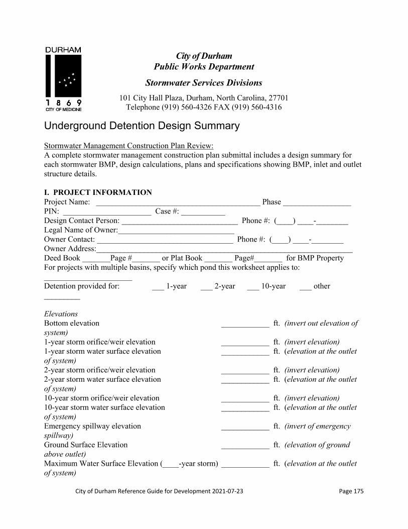
City of Durham Reference Guide for Development 2021‐07‐23 Page 175
City of Durham Public Works Department
Stormwater Services Divisions
101 City Hall Plaza, Durham, North Carolina, 27701 Telephone (919) 560-4326 FAX (919) 560-4316
Underground Detention Design Summary Stormwater Management Construction Plan Review: A complete stormwater management construction plan submittal includes a design summary for each stormwater BMP, design calculations, plans and specifications showing BMP, inlet and outlet structure details. I. PROJECT INFORMATION Project Name: _________________________________________ Phase _________________ PIN: ______________________ Case #: ___________ Design Contact Person: _____________________________ Phone #: (____) ____-________ Legal Name of Owner:_____________________________ Owner Contact: __________________________________ Phone #: (____) ____-________ Owner Address:________________________________________________________________ Deed Book _______Page #_______ or Plat Book _______ Page#_______ for BMP Property For projects with multiple basins, specify which pond this worksheet applies to: ______________________ Detention provided for: ___ 1-year ___ 2-year ___ 10-year ___ other _________ Elevations Bottom elevation ____________ ft. (invert out elevation of system) 1-year storm orifice/weir elevation ____________ ft. (invert elevation) 1-year storm water surface elevation ____________ ft. (elevation at the outlet of system) 2-year storm orifice/weir elevation ____________ ft. (invert elevation) 2-year storm water surface elevation ____________ ft. (elevation at the outlet of system) 10-year storm orifice/weir elevation ____________ ft. (invert elevation) 10-year storm water surface elevation ____________ ft. (elevation at the outlet of system) Emergency spillway elevation ____________ ft. (invert of emergency spillway) Ground Surface Elevation ____________ ft. (elevation of ground above outlet) Maximum Water Surface Elevation (____-year storm) ____________ ft. (elevation at the outlet of system)

City of Durham Reference Guide for Development 2021‐07‐23 Page 176
Areas Drainage area ____________ ac. (total drainage to the facility) Volumes Total Storage Volume Provided ____________ ft3 (volume detained at design storm)
Discharges (Specify only applicable frequency events)
At BMP 1-year 2-year 10-year _____-year Inflow ________ cfs ________ cfs ________ cfs ________ cfs Routed outflow ________ cfs ________ cfs ________ cfs ________ cfs
At Analysis Point(s) that BMP Contributes to 1-year 2-year 10-year _____-year Pre-development ________ cfs ________ cfs ________ cfs ________ cfs Post-development w/o detention ________ cfs ________ cfs ________ cfs ________ cfs With detention ________ cfs ________ cfs ________ cfs ________ cfs System Information 1-year storm orifice/weir diameter_____ in. length ________ft. 2-year storm orifice/weir diameter_____ in. length ________ft. 10-year storm orifice/weir diameter_____ in. length ________ft. ___- year storm orifice/weir diameter_____ in. length ________ft. Principal spillway diameter_____ in. Emergency spillway width_____ ft. side slopes ___:1 slope_____% II. REQUIRED ITEMS CHECKLIST The following checklist outlines design requirements. In the space provided to indicate the following design requirements have been met and supporting documentation is attached. Applicant’s initials ____________ a. Riprap outlet protection, if provided, reduces flow to non-erosive velocities
(provide calculations).

City of Durham Reference Guide for Development 2021‐07‐23 Page 177
____________ b. The system consists of two 60-inch minimum header pipes and two 60-inch minimum perimeter pipes. 36-inch interior pipes for additional storage are provided if needed.
____________ c. Manhole access has been provided at the 4 corners of the system. ____________ d. Traffic bearing cleanouts have been provided every 100-feet with a minimum
of two per pipe run. Manholes may be counted as cleanouts. ____________ e. A traffic bearing door (bilco type or approved equal) has been placed at the inlet
and outlet of the system. ____________ f. Spacing of pipe runs are per the manufacturer’s specification. ____________ g. The backfill material has been certified by a Geotechnical Engineer. ____________ h. The system is water tight for the 10-year hydrostatic pressure calculated at the
inlet to the system. ____________ i. A surface or sub-surface bypass has been sized to safely convey the maximum
required design storm. ____________ j. An operation and maintenance plan for the system has been provided. ____________ k. A recorded drainage easement is provided for each basin including access to the
nearest right-of-way and is graded per Section 8.3, Stormwater Control Facilities (BMPs).
____________ l. A plan view of the system with grading shown is provided ____________ m. A profile through the system and emergency bypass is provided. Water surface
elevations are shown on the profile. ____________ n. Outlet structure details are provided. ____________ o. Compaction specifications for the installation of the system are provided on the
plan. Note: Executed Stormwater Facility Operation and Maintenance Permit Agreement, payment of permit fee per facility and payment of surety are required prior to construction drawing approval.

City of Durham Reference Guide for Development 2021‐07‐23 Page 178
Section 8.5:
This section is intentionally left blank.

City of Durham Reference Guide for Development 2021‐07‐23 Page 179
Section 8.6: As‐built Certification Requirements for
SCMs in the City of Durham
8.6.1 As‐built Program Description
A. Introduction
A licensed North Carolina Professional Engineer (NCPE), who is competent in the design and construction of stormwater control measures (SCMs), as well as who has observed and inspected the stormwater facility during construction, is required to submit an SCM As-built Certification (“Certification”) of the constructed SCM after it has been completed. It is understood that sometimes the certifying engineer may not be the same engineer that designed the original SCM. The Certification consists of the provision of as-built drawings and supporting information demonstrating that the SCM was constructed in a manner that accomplishes its designed functions and should provide years of adequate service without substantial reconstruction.
B. Program Objectives
The overall objectives of the City’s As-built Program are three-fold:
1. To improve the quality of SCM being constructed in the City is satisfactory.
2. To improve customer service by decreasing review times for Certifications through standardized submittals.
3. To reduce the work load of construction compliance assessments by requiring the as-built engineer to be the primary point of contact and inspector during construction.
C. Steps in As‐built Process
The steps in the as-built process begin at the point after clearing and grubbing and prior to construction commencement. This is typically when construction drawings are approved and a pre-construction meeting is held:
1. Pre-construction Meeting – An SCM pre-construction meeting must be held with Stormwater Development Review prior to the start of SCM construction. This meeting is to include the construction contractor, design/as-builting engineer(s), and geotechnical engineer as needed. The owner/developer may also attend if they wish. This meeting is required prior to the issuance of water and sewer permits, or for a residential subdivision, prior to final plat approval; however it can and usually does occur earlier in the development process. However, if the SCM has an earthen embankment dam and it will be constructed and used temporarily as a sedimentation and erosion control device, it is necessary to hold the SCM pre-construction meeting prior to the dam being constructed.
To schedule, call the Stormwater Development Review SCM Technician at 919-560-4326 Ext. 30238 a minimum of three business days prior to the desired meeting date.
City of Durham Reference Guide for Development 2021‐07‐23 Page 180
Please note that a separate pre-construction meeting regarding utilities, etc., must be scheduled with the City of Durham Engineering Inspections. Click request form at http://durhamnc.gov/667/Engineering-Inspections or email [email protected] 48 hours prior to the desired pre-con time.
2. Construction Inspections
a. By the certifying engineer: The North Carolina licensed professional engineer who will certify the as-builts, or someone directly under the supervision of that engineer, must inspect at a minimum the installation of the critical SCM components detailed in Section 8.6.2. The critical components applicable to a project’s specific SCM will be discussed during the project’s stormwater pre-construction meeting. It is therefore the responsibility of the contractor to inform the certifying engineer at least 48 hours before these components are being installed.
b. By the City: As allowed by his/her workload, the Stormwater Development Review SCM Technician will inspect the installation of all critical SCM components (see Section 8.6.2). The contractor must inform the SCM Technician 48 hours prior to the installation of each key component – call (919) 560-4326, ext. 30238, or e-mail [email protected]. Note that these inspections are courtesy inspections, not pass/fail inspections, to help ensure construction is reasonably progressing in an acceptable manner so issues noted during the inspection can be more easily remedied and not become major problems at the end. If the SCM Technician is unavailable for an inspection, the contractor should proceed with the work while the certifying engineer inspects and adequately documents that the work was done per the plans.
3. Geotechnical Certification – This certification must be submitted within four weeks of the construction of the dam being completed. See Section 8.6.4 for this form.
4. As-built Submittal – The certifying engineer shall submit the as-built package only after construction of the SCM is complete. This includes at least 85% establishment of all vegetation associated with the SCM, such as wetland plants, grass on embankment dam, slopes, access, etc., as well as ensuring the drainage area to the facility is stabilized.
5. As-built Review – Once the as-built package has been submitted, Stormwater Development Review’s review will be due within 10 business days. The review will include a field inspection of the SCM. If the reviewer has comments on either the documentation package or the field inspection, the as-built package will be returned to the certifying engineer with a comment letter or redlines detailing deficient items.
6. As-built Resubmittal – All resubmittals of as-built packages must include a response to comment document telling how each of Stormwater Development Review’s comments on the previous submittal has been addressed.
7. As-built Approval and SCM Deemed Complete – Once the as-built package is approved and the SCM is deemed complete, Stormwater Development Review will:
a. Release any construction securities associated with the SCM,
b. Release full Certificate of Occupancy for all related building permits, and
c. Issue a Certificate of Completion for the SCM.

City of Durham Reference Guide for Development 2021‐07‐23 Page 181
D. SCM As‐built Package Submittal
The consultant shall submit the SCM as-built submittal package electronically to the Development Services Center online submittal portal. Each SCM will have its own as-built submittal and will be charged a separate review fee.
1. Initial Submittal
The first submittal package shall consist of all of the following:
SCM As-built Drawing Submittal Checklist. Fee = $100 base fee/SCM + 4% technology surcharge. See Section 8.6.4 for a list of required documents.
3. Resubmittals
For resubmittals, the following must be included:
SCM As-built Checklist. Any previously redlined plans and/or documents. Comment response documents. Revised plans and/or documents.
For comment response, the following are required:
For written comments, a written response document. For redlines, provide a note next to the redline explaining how the redline was addressed. If it was
addressed on a different sheet, the note must state which sheet.
4. Digital Files
Digital copies of the required files must be in the following format:
SCM photos: .jpg, .tif or .gif format. Cost accounting: Excel (.xls or .xlsx) format. O&M Manual: MS Word (.doc or .docx) or Excel (.xls or .xlsx) format. Drainage area: AutoCAD.dwg format; ESRI ArcGIS .shp, .shx or .dbf formats. All other documents: pdf format.
The files shall be organized into folders named and numbered exactly according to the following convention shown below. Any folders that are not applicable should be marked “NA” after the folder name and left empty.
1 Executed General Certification
2 Executive Summary
3 As-built Drawings
4 As-built Survey
5 SCM Drainage Area Map
6 SCM Design Summary Sheet

City of Durham Reference Guide for Development 2021‐07‐23 Page 182
7 As-built Hydrologic Modeling
8 SCM Field Checklist
9 Photos
10 Planting Certification Letter
11 O&M Manual (if not previously reviewed and approved during construction drawing review)
12 SCM Cost Accounting
13 Geotechnical Certification (if not previously submitted within 4 weeks of dam completion)
14 Materials Certification
15 Recorded Easement Plat
E. Expectations for Successful As‐built Submittals
1. Completeness
The Certification must be complete, and shall include the following documents in PDF format unless indicated otherwise below.
1. An executed “General Certification.”
2. An Executive Summary.
3. The as-built drawings for the SCM with an executed General Certification on each drawing.
4. The as-built survey plot, including all spot shots, of the SCM and SCM Access and Maintenance Easement, signed and sealed by a Land Surveyor licensed in North Carolina.
5. The drainage area map that delineates the drainage area to the SCM as presented in the approved construction drawings or Stormwater Impact Analysis, with redline markups for any as-built drainage area deviations from the design area. If the engineer has verified there is no difference between the design and the as-built drainage area map, then a clear statement to that effect must be included on the map.
6. Design summary sheet for the facility as approved with the construction drawings, with redline/strikeout changes to show any corrections for the as-built SCM.
7. As-built hydrologic modeling inputs and results.
8. The SCM-specific Field Checklist required by the City.
9. Color digital photographs of all SCM components during their construction and after their completion.
10. The landscape company’s letter certifying the installation of the specific plants at the SCM as required by the approved construction drawings or approved field changes.
11. The Operations and Maintenance Manual for the SCM (electronic file: MS Word format, or if using the NC DEQ template, Excel format). The O&M Manual should now be submitted prior to construction drawing approval. However, if the as-builts are for an older SCM for which the O&M Manual was not included with the construction drawings, it must be included in the as-built package.
12. One (1) copy of a cost accounting for the construction of the SCM (electronic file: Excel format). Note: If the cost accounting results in an amount 110% or greater than the original construction estimate (Engineer’s Opinion of Probable Cost), an additional payment into the City’s Stormwater Facility Replacement Fund will be required if this form of financial guarantee was utilized. This additional payment for one-fourth of the amount greater than 100% of the original approved construction estimate, must be made prior to Certification approval. If construction cost accounting
City of Durham Reference Guide for Development 2021‐07‐23 Page 183
with sufficient supporting documentation results in an amount 90% or less than the original construction estimate, then a stormwater facility replacement payment refund will be provided for one-fourth the amount less than 100%. The refund must be requested in writing and submitted no later than one month after the SCM completion certificate is issued.
13. An original signed and sealed Geotechnical Certification with all supporting geotechnical and materials testing documentation. The Geotechnical Certification should now be submitted within 30 calendar days of the dam embankment construction being completed. However, if the as-builts are for an older SCM for which the embankment construction was already completed, it must be included in the as-built package.
14. An original signed and sealed Materials Certification, with all supporting documentation, for SCMs with filter media.
15. A copy of the recorded plat showing the SCM and SCM Access and Maintenance Easement.
2. Field Changes
All changes made in the field to the SCM design must be approved by the design engineer and Stormwater Development Review before the change is implemented. The construction contractor, design engineer, as-built certifying engineer or geotechnical engineer must contact Stormwater Development Review to ascertain whether the change:
Is allowable as a field change that must be reflected on the as-builts but does not require a formal revision of the approved construction drawings, or
Is significant enough to warrant a formal resubmittal of the construction drawings to obtain official review and approval of the change.
If Stormwater Development Review determines the change is allowable as a field change, a written communication will be sent to this effect. A copy of this written communication shall be included in the as-built package to show that the change was previously approved as a field change.
Should non-compliant changes be made without pre-approval by Stormwater Development Review, the burden is on the certifying engineer to demonstrate that the non-compliant item still meets its intended purpose and is therefore acceptable. The engineer must include both of the following in as-built Executive Summary and the “Additional Comments” box at the end of the relevant Field Checklist:
A description of how the non-compliant item deviates from the standards and/or approved construction drawings.
An explanation of why this deviation is acceptable and how the deviation still meets the intended purpose behind the requirement.
3. Site Inspections
The licensed professional engineer who will certify the as-builts, or someone directly under the supervision of that engineer, must inspect at a minimum the installation of the critical SCM components detailed in Section 8.6.2. In addition, the certifying engineer must personally complete a final SCM inspection in order to be able to complete the Field Checklist for a specific SCM.
However, Stormwater Development Review staff will inspect SCM construction as allowed by their schedules, and, as part of the review of the as-built submittal, Stormwater Development Review staff will perform a field inspection of the SCM and project site.
City of Durham Reference Guide for Development 2021‐07‐23 Page 184
4. Common/Significant Issues Preventing Approval of As‐builts
The following items are often the cause of as-built packages not being approved:
Missing Documentation – Items that are in the list of required documentation and are applicable to the project must be included in the submittal package. If items are missing, either the package will be rejected at intake, or comments will be made about the missing items. Engineers certifying as-built packages should not assume that certain items are not applicable to, or required for, the particular SCM they are certifying unless the description of the item indicates such.
Incomplete Geotechnical Certification – Frequently, the construction of an SCM dam is done early in the project. By the end of the project, certain documents required as part of the geotechnical documentation have been misplaced, or the geotechnical engineer or engineering company involved in testing dam compaction or other geotechnical items is no longer involved. As a result, the geotechnical engineer who ends up certifying the items on the Geotechnical Certification will not certify all of the items on the form.
An incomplete Geotechnical Certification is unacceptable to the City of Durham. The City is requiring an assurance that the dam and associated appurtenances have been properly constructed and are in sound condition. If there are no geotechnical records available from the actual construction of the dam, the certifying geotechnical engineer must do enough post-construction testing to be able to make this certification.
For this reason, the City now requires that the Geotechnical Certification be submitted for our review within 30 calendar days of the dam construction being completed.
Failure of Contractors to Notify Certifying Engineer and Stormwater Development Review SCM Technician in Advance of Key Component Installation – Key SCM components not being correctly installed or being installed with deviations from the plans is typically due to the certifying engineer not being present during the installation of those key components. And that is typically due to contractors not notifying the certifying engineer in advance of the installation of the key SCM components. This may result in the key component needing to be reinstalled or reworked in order to meet the plan specifications and obtain City approval.
Other Required Testing Not Performed – If the water tightness testing for underground detention units or infiltration testing for bioretention areas is not performed or does not yield acceptable results, the SCM as-builts will not be approved. This also applies to any other testing required by the City to be specified on the construction drawings.
SCM Vegetation – The City requires that all SCM vegetation (e.g., grass on dam embankments, slopes and within SCM Access and Maintenance Easement, wetland plants on pond aquatic shelf or in wetland zones, wetland/wet meadow plantings) be established to an 85% standard.
For grass, this means that every square foot of the SCM surface to be planted in grass has achieved at least 85% coverage with the prescribed type of permanent grass. Grass that is not sufficiently established frequently allows erosive conditions to develop.
For aquatic shelves or wetland planting zones, this means that 85% of the plants specified in the planting plan are healthy and thriving. If the plants are young and dormant, achievement of the “healthy and thriving” standard may be difficult to verify, so proof of purchase and planting process per the plant vendor’s recommendations must be provided, including pictures.
See Section 8.6.3 for additional information on establishment of vegetation.
City of Durham Reference Guide for Development 2021‐07‐23 Page 185
Stabilization of SCM Drainage Area – A minimum of 85% of the drainage area of an SCM must be adequately stabilized (e.g., with vegetation, mulch, impervious surface), and any remaining disturbed areas in the drainage area must have sufficient alternate erosion and sediment controls (E&SC) in place to mitigate against the deposition of sediment in the facility. Although gravel surfaces are considered stabilized for the purposes of E&SC, the City does not consider ABC or other stone with a lot of screenings/fines to be stabilized if it lies within an SCM drainage area.
It is highly recommended that 100% of the drainage area to filtration-type SCMs (e.g., sand filters, bioretention areas) be completed per the plans prior to allowing stormwater runoff to enter these SCMs. If excess sediment enters these SCMs, they can become clogged and will not drain at a sufficient rate. As-builts will not be approved if this is the case. A completed drainage area means that all of the permanent surfaces and landscape plantings approved in the site plan have been installed.
8.6.2 Critical Components of SCMs
In order to certify the SCM as-builts, the certifying engineer should at a minimum inspect all the critical components discussed below. As allowed by his/her workload, the Stormwater Development Review SCM Technician will also inspect the installation of all critical SCM components. See below for a list of critical components by SCM type.
It is highly recommended that the contractor inform the SCM Technician 48 hours prior to the installation of a critical component – call (919) 560-4326, ext. 30238, or e-mail [email protected]. Note that these inspections are courtesy inspections to help identify issues, rather than pass/fail inspections. These inspections are intended to help ensure construction is reasonably progressing in an acceptable manner so issues noted during the inspection can be more easily remedied and not become major problems at the end. If the SCM Technician is unavailable for an inspection, the contractor should proceed with the work while the certifying engineer inspects and adequately documents that the work was done per the plans.
A. Wet Detention Basin, Stormwater Wetland, Dry Detention Basin,
Bioretention and Aboveground Sand Filter Critical Components
Key Trench Excavation: An onsite inspection while excavation is open is required to confirm consistency with approved construction design plan.
Principal spillway pipe and associated components: An inspection of the interior of the pipe prior to covering/backfilling is needed to: verify proper alignment of joints, proper bedding, and wrapping of joints in NCDOT Type II filter fabric. In addition, the following are considered critical components associated with the principal spillway pipe:
Concrete Cradle: must be inspected after any required formwork is installed and prior to concrete being poured.
Anti-Seep Collars: must be inspected after any required formwork is installed and prior to concrete being poured.
Seepage Diaphragm: all stages of construction must be inspected, beginning with forms or trench for filter material. Must include inspection of any seepage conveyance pipe. Note: seepage diaphragms are usually built in two or more stages.
Outlet structure(s) and associated anti-flotation ballast: Provide two working days’ notice once riser has been set, after any required formwork is installed, and prior to any portion of the concrete anti-flotation ballast being poured.
City of Durham Reference Guide for Development 2021‐07‐23 Page 186
Any site-constructed reinforced concrete structures (such as spillways, weir walls, retaining walls, inlet and outlet structures, etc.): Provide two working days’ notice for construction oversight inspection of reinforcing steel placement and formwork prior to concrete pours.
B. Sand Filter and Bioretention Critical Components
Subgrade or constructed foundation: An onsite inspection prior to covering it with materials, etc., is required.
Outlet structure or riser device in combination with connecting underdrains: An oversight inspection is required. Note that no filter socks are to be placed on underdrains. Additionally, no filter fabric shall be placed between media layers in bioretention areas. The contractor is to provide notification when both have been installed and prior to placing any gravel/sand/media over or around any of the components.
Principal spillway pipe: An inspection prior to covering/backfilling to verify proper alignment of joints and verify proper bedding is required.
Any site-constructed reinforced concrete structures (such as spillways, weir walls, retaining walls, outlet structures, etc.): Provide two working days’ notice for construction oversight inspection of reinforcing steel placement and formwork prior to concrete pours.
Filter media: Sand, gravel, or proprietary media must be verified to be per the specification in the plans prior to placement. No substitutions of specified material shall be allowed without design engineer and Stormwater Development Review approval. Pay particular attention to the minimum thickness of each layer, overall depth, and conformity to the approved construction plans.
An infiltration/permeability test is required for the installed media in a bioretention area.
C. Underground Detention Critical Components
Subgrade or constructed foundation: An onsite inspection prior to covering it with materials, etc., is required.
Precast unit, bottom portion: If the device is precast it will often come in two pieces, a top and a bottom. The installation of the bottom portion of the device prior to the top being set in place requires an oversight inspection.
A 24-hour water tightness test is required for underground detention units.
G. Level Spreader Critical Components
Any concrete structures (such as flow splitters, bypass structures, weir walls, level spreader lip): 48 hours notification is required prior to installation of these items.
H. Rainwater Harvesting System Critical Components
Underground cisterns: An onsite inspection of the subgrade or constructed foundation is required.
Water tank and any connecting pipes: The installation of these items requires inspection prior to backfill if they are below ground.
Pumps and timers or other automated devices: These devices are to be field tested and proven functional. Field demonstration of these devices is required prior to City approval.
City of Durham Reference Guide for Development 2021‐07‐23 Page 187
8.6.3 Vegetation Establishment
Vegetation establishment is the single biggest obstacle to completing an SCM to City as-built standards. The City requires all SCM vegetation (e.g., grass on dam embankments, slopes and within SCM Access and Maintenance Easement, wetland plants on pond aquatic shelf or in wetland zones, wetland/wet meadow plantings) to be established to an 85% standard.
For grass, this means that every square foot of the SCM surface to be planted in grass has achieved at least 85% coverage with the prescribed type of grass. Grass that is not sufficiently established frequently allows erosive conditions to develop.
For aquatic shelves or wetland planting zones, this means that 85% of the plants specified in the planting plan are healthy and thriving. If the plants are young and dormant, achievement of the “healthy and thriving” standard may be difficult to verify. In this case, as-built approval will be delayed until a point in time when the plans begin to green up and leaf out.
Vegetation establishment issues that Stormwater Development Review has often seen are:
Vegetation is not established to the 85% standard discussed above, but the certifying engineer submits the as-builts anyway.
Insufficient topsoil has been provided for grass, sod, and wetland plants to root into.
Sod is not rooted in, but merely placed on top of the soil. Sod has not been watered until it is rooted in and subsequently dies.
If the grass is seeded, rather than sodded, 85% of the seeded area must have germinated. Grass seed that is sowed and then is either washed away or does not germinate with sufficient coverage will not result in a determination that the SCM has been satisfactorily complete. In many instances it has been observed that the straw mulching or matting is not adequately tacked or secured, thus allowing it to be easily displaced or bypassed. It has been further observed that supplemental watering does not take place during critical times of establishment.
Wetland plants are often eaten by geese when they are young. If this occurs prior to the as-builts being approved, the wetland plants must be replanted and must become established enough to be deemed healthy and thriving.
It is the wrong season for establishing vegetation. For young wetland plants that are planted during the dormant season, it is very difficult to tell whether they are dormant or dead until the weather warms and the growing season commences.
If grass is not sufficiently established and it is the wrong planting season for the type of grass specified, approval of the as-builts will be delayed until the appropriate growing season comes around and full establishment can be verified.
Undesirable vegetation has taken hold rather than the required vegetation. Water primrose and algae in ponds or wetlands indicate excess fertility in the drainage area and too high a concentration of nutrients in the SCM water. Cattails are also undesirable and may take over a pond or wetland, crowding out the desirable plants. Undesirable vegetation must be removed before the SCM can be deemed complete. This also pertains to permanent grass where either a temporary grass is established or invasive weeds out-compete it.
Tips for establishing desired wetland vegetation for wet ponds and wetlands:
City of Durham Reference Guide for Development 2021‐07‐23 Page 188
To prevent geese from eating the wetland plants, a grid pattern of string with flagging over the wetland plant areas, as well as sedimentation and pest exclusion fencing around SCM to keep geese out will help.
Zigzag planting pattern of the aquatic shelf and wetland plant zones are more successful in getting plants established than is a straight-line planting pattern.
It is more important to put the wetland plants in the correct zones per as-built surveyed elevations than per the design layout on plans. Even a few inches of elevation difference can be key when determining zones. This requires careful surveying of the wetland plant zones prior to planting.
Using the outlet structure, flood the pond/wetland for a few weeks prior to planting the desired vegetation – this will help kill off undesirable vegetation. Then open the bottom drain valve or otherwise use the outlet structure to drain the pond down somewhat below the permanent pool elevation. While the exposed soil is still mucky, plant the wetland plants. Keep the water level relatively low until the plants are well-established, then raise it to the normal pool level using the outlet structure controls.
In the first two weeks after planting, the wetland plants will likely undergo “transplant shock.” After that (provided they are planted during growing season), they should start to green up. However, this is when geese do the most damage.
If planting in cooler weather when the plants are dormant, they will not need much water. However, in warmer weather, the plants may need to be watered daily if the water level in the impoundment dictates.
8.6.4 Certification Forms and Documents
The following forms are required for each Certification:
General As-Built and Construction Certification. This form is required for all Certifications.
Geotechnical Certification for Dams. This is required for all Certifications of SCMs that include an earthen dam and must be submitted immediately after completion of the dam and all outlet conveyances within the dam. Failure to submit within 30 days of dam completion will be considered a public safety issue, which will affect the future release of building permits and/or certificates of occupancy for the project.
Materials Certification for SCMs with filter media.
Field Checklists for individual SCMs, as applicable:
o Field Checklist for Dry Ponds, Wet Ponds, Constructed Wetlands
o Field Checklist for Open Sand Filters
o Field Checklist for Closed Sand Filters
o Field Checklist for Underground Detention Systems
o Field Checklist for Closed Sand Filter with Underground Detention
o Field Checklist for Bioretention Areas
o Field Checklist for Level Spreader-Vegetated Filter Strip Systems
o Field Checklist for Vegetated Water Quality Swales
o Field Checklist for Rainwater Harvesting Systems
o Field Checklist for Permeable Pavement

City of Durham Reference Guide for Development 2021‐07‐23 Page 189
o Field Checklist for Filterra® Units
o Field Checklist for StormFilter® by Contech
o Field Checklist for Silva Cell Suspended Pavement with Bioretention
The above forms are provided on the following pages. Field Checklists for SCMs not mentioned above will be developed as new types of SCMs are approved for use in the City of Durham.

City of Durham Reference Guide for Development 2021‐07‐23 Page 190
General As‐Built and Construction Certification
SCM Facility Name Click here to enter text.
Note: This certification statement must be executed by a licensed North Carolina Professional Engineer with experience in the design, construction, and operation of SCMs of a nature similar in scope to that certified to in this certification. Observation/supervision of the above-listed critical SCM components and a final assessment for design compliance by the certifying licensed professional engineer will be required to complete this certification.
CERTIFICATION STATEMENT
Based upon (1) my observation of the construction of this facility, (2) my review of the as-built survey data, (3) my review of the drainage area treated or managed by the facility, and (4) my analysis of the hydraulic performance of the constructed facility, I hereby certify that the (A)
hydrologic and hydraulic, (B) geometric, (C) public safety, (D) facility access, (E) drainage area1, and (F) vegetative elements of the constructed facility are in compliance with the requirements of
the facility as set forth in the approved Construction Drawings, approved design documents, and/or any approved modifications. Furthermore, I certify that the red-noted exceptions do not
adversely affect the required performance or public safety aspects of the facility.
Note 1: The drainage area treated by the facility must, at a minimum, be equivalent to the area proposed for treatment in the approved construction drawings. In addition, a minimum of 85% of the drainage area to the facility must be adequately stabilized (e.g., with vegetation, mulch, impervious surface), and any remaining disturbed areas in the drainage area must have sufficient alternate controls in place to limit the deposition of sediment in the facility. If these drainage area requirements are not met, the Certification will be disapproved.
The following supporting documents are included in the formats required below. Note: All digital files must be in Adobe Acrobat (.pdf) format unless indicated otherwise below.
1. An executed “General Certification.”
2. An Executive Summary describing the results of the as-built process, including any field changes and the results of remodeling the SCM under as-built conditions. Any item not meeting any minimum requirement and requesting to be accepted shall clearly be noted and the certifying engineer shall provide the following:
a. A description of how the non-compliant item deviates from the standards and/or approved construction drawings.
b. An explanation of why this deviation should be acceptable and how the deviation still meets the intended purpose behind the requirement.
3. As-built Drawings: One (1) copy of the approved construction drawings for the SCM with redline/strikeout changes to show any changes for the as-built SCM. All approved construction drawing sheets signed by Stormwater must be included, but the full set of construction drawings is not required or desired. All sheets must contain the executed General Certification, i.e., the statement in the box above must appear on the as-built drawings and must be signed and sealed by the certifying engineer.
4. The as-built survey, including all spot shots, of the SCM. Note that the survey plot must be signed and sealed by a Land Surveyor licensed in North Carolina. The plot must also include spot shots for all grade changes/break points and critical inverts, and all field values for elevations and dimensions shown on the approved construction drawings must be verified by the surveyor.
City of Durham Reference Guide for Development 2021‐07‐23 Page 191
In addition, the access to the facility and top of the dam shall be surveyed sufficiently to assess whether it is a minimum of 10 feet wide, and has a maximum centerline grade and cross-slope of fifteen percent (15%) and ten percent (10%) respectively.
The following Field Survey Certification Statement must be included on the as-built survey plot:
5. One (1) copy of the drainage area map that delineates the drainage area to the SCM as presented in the approved construction drawings or Stormwater Impact Analysis, with redline markups for any as-built drainage area deviations from the design area. The area in square feet or acres for both the design and the as-built drainage areas should be quantified on the map.
The entire as-built drainage area does not need to be formally surveyed, but the ridge lines do need to be verified. Roof drain connections should be verified to ensure that roof drainage is routed as determined at the design stage.
If the engineer has verified there is no difference between the design and the as-built drainage area map, then a clear statement to that effect must be included on the map.
6. One (1) copy of the design summary sheet for the facility as approved with the construction drawings, with redline/strikeout changes to show any corrections for the as-built SCM.
7. One (1) copy of the hydrologic modeling inputs and results, using as-built data for the drainage area and SCM.
8. An original completed copy of the signed and sealed SCM-specific Field Checklist required by the City. A complete Checklist shall contain no non-compliant items. Note: If, while completing the Checklist, a non-compliant item is noted at an SCM by the certifying engineer, a Certification for that SCM should not be submitted until the non-compliant item has been brought into compliance.
If the engineer believes the non-compliant item still meets its intended purpose and is therefore acceptable, the engineer must include both of the following in the “Additional Comments” box at the end of the Field Checklist:
a. A description of how the non-compliant item deviates from the standards and/or approved construction drawings.
b. An explanation of why this deviation is acceptable and how the deviation still meets the intended purpose behind the requirement.
Final approval of a non-compliant item shall be based primarily on supporting justification. However, also factored into the City’s approval or disapproval are:
Consistency – whether or not the City has approved this type of non-compliance at other SCMs, and
Experience – whether this type of non-compliance has been approved previously and then over time has proved to be inadvisable.
FIELD SURVEY CERTIFICATION STATEMENT
I, ________________________________________, as a duly licensed Professional Land Surveyor in the State of North Carolina, hereby certify that the data shown on this drawing, obtained under my supervision, is an accurate and complete representation of what was constructed in the field and that the physical dimensions or elevations shown are thus as-built conditions, except otherwise noted hereon.
City of Durham Reference Guide for Development 2021‐07‐23 Page 192
9. Color photographs of all SCM components (as shown on approved SCM plan and detail sheets) during their construction and after their completion. This includes an overall view of the SCM and individual components to include the dam, emergency spillway, riser, outfall structure, outfall area, impoundment area, access way, etc. (electronic format: .jpeg, .gif or .tiff).
10. One (1) copy of the landscape company’s letter certifying the installation of the specific plants at the SCM as required by the approved construction drawings or approved field changes. This letter must be on the company’s letterhead, must list all of the plant species planted, and how many of each were planted. In lieu of listing all species and the number planted, the landscape company may attach to the letter the purchase receipts or bills of lading for the plants.
11. One (1) copy of an Operations and Maintenance Manual for the SCM (electronic file: MS Word format, or if using the NC DEQ template, Excel format). The O&M Manual should now be submitted prior to construction drawing approval. However, if the as-builts are for an older SCM for which the O&M Manual was not included with the construction drawings, it must be included in the as-built package.
12. One (1) copy of a cost accounting for the construction of the SCM (electronic file: Excel format). Note: If the cost accounting results in an amount 110% or greater than the original construction estimate (Engineer’s Opinion of Probable Cost), an additional payment into the City’s Stormwater Facility Replacement Fund will be required if this form of financial guarantee was utilized. This additional payment, for one-fourth of the amount greater than 100% of the original approved construction estimate, must be made prior to Certification approval. If construction cost accounting with sufficient supporting documentation results in an amount 90% or less than the original construction estimate, then a stormwater facility replacement payment refund will be provided for one-fourth the amount less than 100% with a written request submitted no later than one month after the SCM completion certificate is issued.
13. An original signed and sealed Geotechnical Certification with all supporting geotechnical and materials testing documentation. The Geotechnical Certification should now be submitted within 30 calendar days of the construction of the dam embankment being completed. Failure to submit within 30 calendar days of dam completion will be considered a public safety issue, which will affect the future release of building permits and/or certificates of occupancy for the project. However, if the as-builts are for an older SCM for which the embankment construction was already completed, it must be included in the as-built package.
14. An original signed and sealed Materials Certification, with all supporting documentation, for SCMs with filter media.
15. A copy of the recorded plat showing the SCM and SCM Access and Maintenance Easement.
Name: ___________________________________________________ Date: ________
NCPE Seal:
City of Durham Reference Guide for Development 2021‐07‐23 Page 193
Geotechnical Certification for Dams and Seepage Controls
SCM Facility Name Click here to enter text.
Note: This certification statement must be provided for all earthen embankment dams and must be executed by a licensed North Carolina Professional Engineer (NCPE) with experience in the design and construction of small earth dams of a nature similar in scope to that certified to in this certification. For all dams with greater than 5 feet of depth of water impounded in it at normal water level, this certification must be executed by a licensed NCPE with geotechnical engineering expertise. Periodic observations of construction and a final assessment for design compliance by the certifying engineer or personnel under their direct charge is required to complete this certification.
CERTIFICATION STATEMENT Based upon my observation, monitoring, and testing of the construction of the dam and seepage
controls (if applicable) for this facility, I hereby certify that the constructed facility is in compliance with the geotechnical requirements as set forth in the approved Construction Drawings, approved
design documents, and any approved modifications.
The following supporting documents are included in electronic formats (Note: All documents in the electronic files must be in PDF format unless indicated otherwise below):
1. Copies of all dam embankment material composition and density testing paperwork, including a map that labels all points where the dam and dam foundation areas were tested. Note: Insufficient testing in the zones over and around the principal outlet works for the dam will render this certification invalid.
2. Copies of all concrete compressive strength testing paperwork for any cast-in-place concrete items associated with the construction of the dam. Testing is required for structural components such as reinforced concrete dams/weir walls, concrete emergency spillways, poured-in-place underground detention facilities, etc.
3. One (1) copy of the purchase receipt for any principal spillway pipe that is Class IV or greater. The purchase receipt should identify the ASTM specifications governing the manufacture of the pipe.
4. Colored digital photographs showing the dam foundation areas, the riser, the principal spillway pipe, the concrete cradle, the seepage diaphragm, relief drains, etc., as those items were being prepared and installed (electronic format: .jpg, .gif or .tif).
5. One (1) copy of the certifying engineer’s resume that demonstrates required geotechnical engineering expertise when the dam is impounding greater than 5 feet of water at normal water level.
Name: ___________________________________________________ Date: ________
NCPE Seal:
City of Durham Reference Guide for Development 2021‐07‐23 Page 194
Materials Certification for SCMs with Filter Media (except Filterras® and
StormFilters®)
SCM Facility Name Click here to enter text.
Note: This certification statement must be executed by a registered North Carolina Professional Engineer with experience in the design, use, identification, and materials testing of SCMs with filter media. Observation of the installation of the filter media used in this SCM will be required to complete this certification.
CERTIFICATION STATEMENT
Based upon my observation and monitoring of the installation of the filter media used in this facility, and based on my testing of the media or my review of the media test results, I hereby
certify that the filter media used in this constructed facility is in compliance with the filter media requirements of the facility, as proscribed in the approved Construction Drawings, approved
design documents, and any approved modifications.
The following supporting documents are included in hard copy and electronic file formats (Note: All electronic files must be in PDF format unless indicated otherwise below):
1. [Digital only] One (1) copy of the materials testing paperwork for the materials used in the filter media section, that demonstrates compliance with the following requirements:
a. For sand filters: cleaned, washed, coarse concrete sand such as ASTM C33. The sand particles shall be less than 2 mm average diameter.
b. For bioretention areas and Silva Cells:
i. Media gradation and composition as specified on the plans.
ii. Phosphorus Index less than 30.
iii. In-situ infiltration rate of one to six inches per hour.
2. [Digital only] One (1) copy of the purchase receipts or bill of lading for the materials used in the filter media section.
3. [Digital only] Color photographs that document the installation of each layer of the filter media, including the underdrain portion (and cleanouts) of the filter media section, used in this facility (electronic format: .jpg, .gif, or .tif).
Name: ___________________________________________________ Date: ________
NCPE Seal:
City of Durham Reference Guide for Development 2021‐07‐23 Page 195
Field Checklist for
Dry Ponds, Wet Ponds, Constructed Wetlands, and Pocket Wetlands
Date of Certification Assessment: ____________________
Assessing and Certifying NCPE: _______________________________ Seal:
SCM Facility Name: ___________________________________________
Access Address: _________________________________________________________
PIN/s of Parcel/s Where the Facility is Sited: ______________________________
CHECKLIST All items in this checklist must be compliant. If an item is not applicable, write “N/A” next to the item. If the engineer believes the non-compliant item still meets its intended purpose and is therefore acceptable, he/she must include both of the following in the “Additional Comments” box at the end of this form:
A description of how the non-compliant item deviates from the standards and/or approved construction drawings.
An explanation of why this deviation is acceptable and how the deviation still meets the intended purpose behind the requirement.
A. Open Space The SCM and access way(s) are located entirely on open space property (residential areas only).
[Note: This restriction shall not apply to inlet pipes/channels.]
B. Drainage Area The drainage area to the facility is as per the design documents, or if there are deviations from the
design drainage area, these deviations do not render the SCM undersized or result in insufficient on-site treatment to meet regulatory requirements.
The drainage area to the facility is completely stabilized, and no excess sediment is discharging into the facility.
C. Easements and Accessibility The SCM access way as constructed matches what is shown on the recorded final plat and is fully
contained in the SCM Access and Maintenance Easement.
The SCM Access and Maintenance Easement is clear of obstructions and traversable by anticipated maintenance equipment.
Unobstructed maintenance vehicle access has been provided to the control structure and all inlets, and access to the facility and top of the dam meets the following conditions per field observation and survey spot shot data:

City of Durham Reference Guide for Development 2021‐07‐23 Page 196
o It is a minimum of 10 feet wide.
o It has a maximum centerline grade of fifteen percent (15%).
o It has a maximum cross-slope of ten percent (10%).
Unless it has been surfaced with gravel, asphalt, concrete, etc., in accordance with approved construction drawings, 85% of the SCM Access and Maintenance Easement has achieved a healthy stand of grass.
D. Inlets and Forebay Riprap energy dissipators and sediment forebays have been installed at the inlets in accordance with
the construction drawings.
All inlet pipes have been installed with appropriate end treatments and curtain walls in accordance with the construction drawings.
All inlet pipes are well homed and securely attached/grouted to their headwalls/flared end sections. The joints are smoothly finished with no evidence of gaps, cracks, and spalling.
All accumulated sediment and other debris in the sediment basins, riprap energy dissipators, and forebay/s has been removed.
Forebay berm has been constructed in accordance the approved construction drawings, and top of berm is no deeper than one foot below permanent pool.
E. Impoundment Area The narrowest width of the aquatic shelf is ________.
The positioning of the aquatic shelf is in accordance with the construction drawings.
All accumulated sediment and other debris in the pond floor has been removed.
85% of the plants shown on the planting plan for the SCM are thriving.
The SCM has a minimum length:width ratio of 1.5:1.
F. Dam Embankment The key trench has been installed per the approved construction drawings.
All seepage control devices (anti-seep collars, concrete cradles, filter diaphragms, etc.) have been installed in accordance with the approved construction drawings.
The narrowest top of dam width is ________.
The steepest slope on the upstream face of the dam is ________.
The steepest slope on the downstream face of the dam is ________.
Based on manual rod probings of the dam, particularly in the zones over and around the principal spillway pipe, the dam appears to have been well compacted.
The dam and dam foundation, groin, toe, and abutment areas are completely free of trees, landscaping, and other woody growth.
The dam has been fine graded and is free of ruts, erosion, wood, construction debris, etc.
City of Durham Reference Guide for Development 2021‐07‐23 Page 197
85% of the SCM slopes (cut slopes and dam embankment) and dam foundation, groin, toe, and abutment areas has achieved a healthy stand of grass. The dam is not overgrown and there is no undesirable vegetation.
No evidence of seepage was noted on the downstream face of the dam.
G. Emergency Spillway The narrowest width of the control section is ________.
The side slopes of the control section are [Left] ________ and [Right] ________.
The size, shape, and alignment of the exit channel are in accordance with the construction drawings.
Armoring has been installed in accordance with the construction drawings.
The spillway has been fine graded and is free of ruts, erosion, etc.
Excluding the hard-surfaced armored area, 85% of the spillway has achieved a healthy stand of grass. The spillway is not overgrown and there is no undesirable vegetation.
H. Riser/Control Structure The riser/control structure is reinforced concrete.
The diameter or opening dimensions of the riser is/are ________.
A top, peak-roofed trash rack has been provided and bolted down to the riser.
A trash rack access hatch (minimum 2’ × 3’) and steps down the inside of the riser have been provided.
At least one side of the riser is accessible by foot during permanent pool conditions and direct access from dam embankment is provided.
A drawdown valve with an accessible operating mechanism has been provided in accordance with the approved construction drawings.
The riser structure and all appurtenant devices (plug valve, etc.) appear to be sound.
For precast structures, the barrel sections were installed with gasketted joints, adjacent riser barrel sections have been bolted together with stainless steel strapping, and there is no evidence of leakage at the joints.
All orifices, siphons, ports, and weirs were installed in accordance with the construction drawings.
The anti-flotation ballast has been provided in accordance with the construction drawings.
A placed concrete invert to the invert out of the principal spillway pipe has been provided.
The riser is free of debris or obstructions.
I. Principal Spillway Pipe The principal spillway pipe (PSP) is reinforced concrete.
The diameter of the PSP is ________.
The principal spillway pipe was wrapped with a layer of geotextile filter fabric on the outside of each pipe joint.
Based on a visual inspection, it appears that the joints of the PSP were “homed” reasonably well, and it appears that no joints are leaking.
City of Durham Reference Guide for Development 2021‐07‐23 Page 198
No piping (loss of soil) is evident around the PSP.
J. Outfall Structure The outfall structure is per the approved construction drawings and there is no evidence of stability
issues.
The outfall structure has been constructed with a curtain wall, if required.
The principal spillway pipe is securely attached/grouted to the headwall or downstream manhole, and this joint is smoothly finished with no evidence of gaps, cracks, or spalling.
K. Outfall Area If required, a level spreader-vegetated filter strip system or energy dissipator has been provided in
accordance with the construction drawings.
The outfall area and downstream channel(s)/receiving area appears stable (no evidence of erosion or head-cutting), and all accumulated silt and debris has been removed.
Additional Comments by Certifying Engineer:

City of Durham Reference Guide for Development 2021‐07‐23 Page 199
Field Checklist for
Open Sand Filters
Date of Certification Assessment: ____________________
Assessing and Certifying NCPE: _______________________________ Seal:
SCM Facility Name: ___________________________________________
Access Address: _________________________________________________________
PIN/s of Parcel/s Where the Facility is Sited: ______________________________
CHECKLIST All items in this checklist must be compliant. If an item is not applicable, write “N/A” next to the item. If the engineer believes the non-compliant item still meets its intended purpose and is therefore acceptable, he/she must include both of the following in the “Additional Comments” box at the end of this form:
A description of how the non-compliant item deviates from the standards and/or approved construction drawings.
An explanation of why this deviation is acceptable and how the deviation still meets the intended purpose behind the requirement.
A. Drainage Area The drainage area to the facility is as per the design documents, or if there are deviations from the
design drainage area, these deviations do not render the SCM undersized or result in insufficient on-site treatment to meet regulatory requirements.
The drainage area to the facility is completely stabilized, and no excess sediment is discharging into the sediment chamber or sand filter.
B. Easements and Accessibility The SCM access way as constructed matches what is shown on the recorded final plat and is fully
contained in the SCM Access and Maintenance Easement.
The SCM Access and Maintenance Easement is clear of obstructions and traversable by anticipated maintenance equipment.
Unobstructed maintenance vehicle access has been provided to the control structure and all inlets, and access to the facility and top of the dam meets the following conditions per field observation and survey spot shot data:
o It is a minimum of 10 feet wide.
o It has a maximum centerline grade of fifteen percent (15%).
o It has a maximum cross-slope of ten percent (10%).

City of Durham Reference Guide for Development 2021‐07‐23 Page 200
Unless it has been surfaced with gravel, asphalt, concrete, etc., in accordance with approved construction drawings, 85% of the SCM Access and Maintenance Easement has achieved a healthy stand of grass.
C. Sediment Chamber (Forebay) The sediment chamber minimum size has been installed in accordance with the construction drawings.
The depth of the sediment chamber is as specified in the construction drawings.
The top of the forebay berm has been installed level, and 100% of the berm has either achieved a healthy stand of turf grass or been armored in accordance with the construction drawings.
All accumulated sediment and other debris in the sediment chamber has been removed.
All inlet pipes have been installed with appropriate end treatments, including curtain walls, in accordance with the approved construction drawings.
All inlet pipes are well homed and securely attached/grouted to their headwalls/flared end sections. The joints are smoothly finished with no evidence of gaps, cracks, and spalling.
D. Sand Chamber The sand chamber minimum size has been installed in accordance with the approved construction
drawings.
The sand chamber has been constructed such that the maximum head above the sand layer is in accordance with the approved construction drawings.
The required sand, choking stone or filter fabric, and gravel layer(s) have been installed in accordance with the approved construction drawings, and there is no sediment in the sand chamber.
The underdrain system has been installed in accordance with the approved construction drawings. All underdrain joints have glued watertight connections.
Solid underdrain cleanouts have been installed in accordance with the approved construction drawings. Screw-on type (or otherwise approved) cleanout caps have been provided for all cleanout pipes.
All side slopes leading to the sand chamber are no steeper than 3:1.
Any flow splitters or bypass systems have been constructed in accordance with the approved construction drawings.
Even flow distribution into the sand chamber has been provided in accordance with the construction drawings and is not creating scour in the sand chamber.
The filter has been observed by the certifying engineer on ____________ [fill in date] to draw down the runoff from the first inch of rainfall (minimum) in a manner consistent with that specified in the approved construction drawings.
E. Dam Embankment The narrowest top of dam width is ________.
The steepest slope on the upstream face of the dam is ________.
The steepest slope on the downstream face of the dam is ________.
Based on manual rod probings of the dam, particularly in the zones over and around the principal spillway pipe, the dam appears to have been well compacted.
City of Durham Reference Guide for Development 2021‐07‐23 Page 201
The dam and dam foundation, groin, toe, and abutment areas are completely free of trees, landscaping, and other woody growth.
The dam has been fine graded and is free of ruts, erosion, etc.
85% of the SCM slopes (cut slopes and dam embankment) and dam foundation, groin, toe, and abutment areas have achieved a healthy stand of grass. The dam is not overgrown and there is no undesirable vegetation.
No evidence of seepage was noted on the downstream face of the dam.
F. Emergency/Outlet Spillway The narrowest width of the control section is ________.
The side slopes of the control structure are [Left] ________ and [Right] ________.
The size, shape, and alignment of the exit channel are in accordance with the construction drawings.
Armoring has been installed in accordance with the construction drawings ________.
The spillway has been fine graded and is free of ruts, erosion, etc.
Excluding the hard-surfaced armored area, 85% of the spillway has achieved a healthy stand of grass. The spillway is not overgrown and there is no undesirable vegetation.
G. Riser/Control Structure The riser/control structure is reinforced concrete.
The diameter or opening dimensions of the riser is/are ________.
A top, peak-roofed trash rack has been provided and bolted down to the riser, or, if the riser is of a different configuration, it has been constructed in accordance with the construction drawings.
A trash rack access hatch (minimum 2’ × 3’) and steps down the inside of the riser have been provided.
The riser structure and all appurtenant devices appear to be sound.
The riser is free of debris or obstructions.
For precast structures, the barrel sections were installed with gasketted joints, adjacent riser barrel sections have been bolted together with stainless steel strapping, and there is no evidence of leakage at the joints.
All orifices, siphons, ports, and weirs were installed in accordance with the construction drawings.
The anti-flotation ballast has been provided in accordance with the construction drawings.
A placed concrete invert to the invert out of the principal spillway pipe (PSP) has been provided.
H. Principal Spillway Pipe The PSP is reinforced concrete with a minimum pipe strength conforming to ASTM C-76 Class III
standards.
The diameter of the PSP is ________.
The principal spillway pipe was wrapped with a layer of geotextile filter fabric on the outside of each pipe joint.

City of Durham Reference Guide for Development 2021‐07‐23 Page 202
Based on a visual inspection, it appears that the joints of the PSP were homed reasonably well, and it appears that no joints are leaking.
No piping (loss of soil) is evident around the PSP ________.
I. Outfall Structure and Outfall Area The principal spillway pipe is securely attached/grouted to the headwall or downstream manhole, and
this joint is smoothly finished with no evidence of gaps, cracks, and spalling.
If not discharging to a storm sewer system:
o The outfall structure has been installed in accordance with the construction drawings and there is no evidence of stability issues.
o Energy dissipation has been provided in accordance with the construction drawings.
o The outfall area and downstream channel(s)/receiving area appear stable, and all accumulated silt and debris has been removed.
If discharging to a storm sewer system, the receiving manhole appears stable and all accumulated silt and debris has been removed.
Additional Comments by Certifying Engineer:

City of Durham Reference Guide for Development 2021‐07‐23 Page 203
Field Checklist for
Closed Sand Filters
Date of Certification Assessment: ____________________
Assessing and Certifying NCPE: _______________________________ Seal:
SCM Facility Name: ___________________________________________
Access Address: _________________________________________________________
PIN/s of Parcel/s Where the Facility is Sited: ______________________________
CHECKLIST All items in this checklist must be compliant. If an item is not applicable, write “N/A” next to the item. If the engineer believes the non-compliant item still meets its intended purpose and is therefore acceptable, he/she must include both of the following in the “Additional Comments” box at the end of this form:
A description of how the non-compliant item deviates from the standards and/or approved construction drawings.
An explanation of why this deviation is acceptable and how the deviation still meets the intended purpose behind the requirement.
A. Drainage Area The drainage area to the facility is as per the design documents, or if there are deviations from the
design drainage area, these deviations do not render the SCM undersized or result in insufficient on-site treatment to meet regulatory requirements.
The drainage area to the facility is completely stabilized, and no excess sediment is discharging into the sediment chamber or sand filter.
B. Easements and Accessibility The SCM access way as constructed matches what is shown on the recorded final plat and is fully
contained in the SCM Access and Maintenance Easement.
The SCM Access and Maintenance Easement is clear of obstructions and traversable by anticipated maintenance equipment.
Unobstructed maintenance vehicle access has been provided to the control structure and all inlets, and access to the facility and top of the dam meets the following conditions per field observation and survey spot shot data:
o It is a minimum of 10 feet wide,
o It has a maximum centerline grade of fifteen percent (15%) and
o It has a maximum cross-slope of ten percent (10%).

City of Durham Reference Guide for Development 2021‐07‐23 Page 204
Unless it has been surfaced with gravel, asphalt, concrete, etc., in accordance with approved construction drawings, 85% of the SCM Access and Maintenance Easement has achieved a healthy stand of grass.
A Bilco®-type door (or approved equivalent) has been placed at the inlets and at the control structure. Access points that occur in areas subject to vehicular traffic are of the traffic bearing type.
All access ways into the unit(s) have steps or ladders installed as shown on the construction drawings. Access ways do not decrease in size from the opening at ground level. Internal sections of the access way are not offset from the opening at the ground level.
Provided openings do not inhibit confined space entry procedures for safety.
All internal sections of the unit can be accessed from an approved access way.
Access to all flow control valves (and/or valve operating handles) is provided from dry areas. Unit can be drained to accommodate maintenance activities and inspections. Method to drain unit appropriately described within operation and maintenance manual.
C. Sediment Chamber The sediment chamber minimum size has been installed in accordance with the construction drawings.
The depth of the sediment chamber is as specified in the approved construction drawings.
The ports and weirs that drain the sediment chamber into the sand chamber have been installed in accordance with the construction drawings.
Any flow splitters or bypass systems have been constructed in accordance with the approved construction drawings.
The foundational support for and the backfill around the structure have been placed in accordance with the construction drawings.
All accumulated sediment and other debris in the sediment chamber has been removed.
All valves, pipe connections, and chamber section joints are sealed and are water tight.
D. Sand Chamber The sand chamber minimum size has been installed in accordance with the construction drawings.
The sand chamber has been constructed such that the maximum head above the sand layer is in accordance with the approved construction drawings.
The foundational support for and the backfill around the structure have been placed in accordance with the construction drawings.
The required sand, choking stone or filter fabric, and gravel layer(s) have been installed in accordance with the approved construction drawings, and there is no sediment in the sand chamber.
The underdrain system has been installed in accordance with the approved construction drawings.
Solid underdrain cleanouts have been installed in accordance with the construction drawings.
All underdrain joints have glued watertight connections. Screw-on type (or otherwise approved) cleanout caps have been provide for all cleanout pipes.
All valves, pipe connections, and chamber section joints are sealed and are water tight.

City of Durham Reference Guide for Development 2021‐07‐23 Page 205
Even flow distribution into the sand chamber has been provided in accordance with the construction drawings and is not creating scour in the sand chamber.
The bottom of the structure is located at least one foot above the seasonal high water table.
The filter has been observed by the certifying engineer on ____________ [fill in date] to draw down the runoff from the first inch of rainfall (minimum) in a manner consistent with that specified in the approved construction drawings.
E. Control Structure and Principal Spillway Pipe The control structure is reinforced concrete.
The dimensions of the structure are ________.
The structure and all appurtenant devices appear to be sound.
The structure is free of debris or obstructions.
The foundational support for and the backfill around the structure have been placed in accordance with the construction drawings.
All orifices, siphons, ports, and weirs were installed in accordance with the construction drawings.
The PSP is reinforced concrete with a minimum pipe strength conforming to ASTM C-76 Class III standards.
The diameter of the PSP is ________.
The principal spillway pipe was wrapped with a layer of geotextile filter fabric on the outside of each pipe joint.
Based on a visual inspection, it appears that the joints of the PSP were “homed” reasonably well, and it appears that no joints are leaking.
Access into the control structure and the sediment and sand chambers has been provided in accordance with the construction drawings.
F. Outfall Structure and Outfall Area The control structure has been installed in accordance with the construction drawings.
The principal spillway pipe is securely attached/grouted to the headwall or downstream manhole, and this joint is smoothly finished with no evidence of gaps, cracks, and spalling.
If not discharging to a storm sewer system:
o The outfall structure has been installed in accordance with the construction drawings and there is no evidence of stability issues.
o Energy dissipation has been provided in accordance with the construction drawings.
o The outfall area and downstream channel(s)/receiving area appear stable, and all accumulated silt and debris has been removed.
If discharging to a storm sewer system, the receiving manhole appears stable and all accumulated silt and debris has been removed.

City of Durham Reference Guide for Development 2021‐07‐23 Page 206
Additional Comments by Certifying Engineer:
City of Durham Reference Guide for Development 2021‐07‐23 Page 207
Field Checklist for
Underground Detention Systems
Date of Certification Assessment: ____________________
Assessing and Certifying NCPE: _______________________________ Seal:
SCM Facility Name: ___________________________________________
Access Address: _________________________________________________________
PIN/s of Parcel/s Where the Facility is Sited: ______________________________
CHECKLIST All items in this checklist must be compliant. If an item is not applicable, write “N/A” next to the item. If the engineer believes the non-compliant item still meets its intended purpose and is therefore acceptable, he/she must include both of the following in the “Additional Comments” box at the end of this form:
A description of how the non-compliant item deviates from the standards and/or approved construction drawings.
An explanation of why this deviation is acceptable and how the deviation still meets the intended purpose behind the requirement.
A. Drainage Area The drainage area to the facility is as per the design documents, or if there are deviations from the
design drainage area, these deviations do not render the SCM undersized or result in insufficient on-site treatment to meet regulatory requirements.
The drainage area to the facility is completely stabilized, and no excess sediment is discharging into the underground detention system.
B. Easements and Accessibility The SCM access way as constructed matches what is shown on the recorded final plat and is fully
contained in the SCM Access and Maintenance Easement. The SCM Access and Maintenance Easement is clear of obstructions and traversable by anticipated
maintenance equipment. Unobstructed maintenance vehicle access has been provided to the control structure and all inlets, and
access to the facility and top of the dam meets the following conditions per field observation and survey spot shot data:
o It is a minimum of 10 feet wide.
o It has a maximum centerline grade of fifteen percent (15%).
o It has a maximum cross-slope of ten percent (10%).
City of Durham Reference Guide for Development 2021‐07‐23 Page 208
Unless it has been surfaced with gravel, asphalt, concrete, etc., in accordance with approved construction drawings, 85% of the SCM Access and Maintenance Easement has achieved a healthy stand of grass.
Manhole access has been provided at the four corners of the system. All access manholes are reinforced concrete manholes conforming to the construction drawings.
Traffic bearing cleanouts have been provided at 100-foot intervals, with a minimum of two provided in each pipe run. Manhole access structures may be counted as cleanouts.
A Bilco®-type door (or approved equivalent) has been placed at the inlets and at the control structure for the underground detention system. Access points that occur in areas subject to vehicular traffic are of the traffic bearing type.
All access ways into the unit(s) have steps or ladders installed as shown on the construction drawings. Access ways do not decrease in size from the opening at ground level. Internal sections of the access way are not offset from the opening at the ground level.
Provided openings do not inhibit confined space entry procedures for safety.
All internal sections of the unit can be accessed from an approved access way.
Access to all flow control valves (and/or valve operating handles) is provided from dry areas. Unit can be drained to accommodate maintenance activities and inspections. Method to drain unit appropriately described within operation and maintenance manual.
C. Underground Storage Chambers/Pipes The correct size, linear footage, and materials for the system have been installed in accordance with the
construction drawings.
The storage pipes and/or precast structures were installed to manufacturer specifications and in accordance with the approved construction drawings.
The foundational support for and the backfill around the storage structure(s) have been placed in accordance with the construction drawings.
All inlet pipes have been installed in accordance with the construction drawings.
The system remains watertight per City of Durham requirements, and a memo from the certifying engineer describing the date and method of certification is attached.
The surface or sub-surface bypass to safely convey the 100-year, 24-hour post-development storm event or the maximum storm has been installed in accordance with the construction drawings.
All accumulated sediment and other debris in the system has been removed.
All valves, pipe connections, and chamber section joints are sealed and are water tight.
D. Control Structure and Principal Spillway Pipe The control structure is reinforced concrete.
The dimensions of the structure are ________.
The structure and all appurtenant devices appear to be sound.
The structure is free of debris or obstructions.
The foundational support for and the backfill around the structure have been placed in accordance with the construction drawings.
City of Durham Reference Guide for Development 2021‐07‐23 Page 209
All orifices, siphons, ports, and weirs were installed in accordance with the construction drawings.
The surface or sub-surface bypass designed to safely convey the 100-year, 24-hour post-development storm event or the maximum storm has been installed in accordance with the approved construction drawings.
The PSP is reinforced concrete with a minimum pipe strength conforming to ASTM C-76 Class III standards.
The diameter of the PSP is ________.
The principal spillway pipe was wrapped with a layer of geotextile filter fabric on the outside of each pipe joint.
Based on a visual inspection, it appears that the joints of the PSP were “homed” reasonably well, and it appears that no joints are leaking.
Steps down the inside of the access manholes have been provided in accordance with the construction drawings.
E. Outlet and Outfall The control structure has been installed in accordance with the construction drawings.
The principal spillway pipe is securely attached/grouted to the headwall or downstream manhole, and this joint is smoothly finished with no evidence of gaps, cracks, and spalling.
If not discharging to a storm sewer system:
o The outfall structure has been installed in accordance with the construction drawings and there is no evidence of stability issues.
o Energy dissipation has been provided in accordance with the construction drawings.
o The outfall area and downstream channel(s)/receiving area appear stable, and all accumulated silt and debris has been removed.
If discharging to a storm sewer system, the receiving manhole appears stable and all accumulated silt and debris has been removed.
Additional Comments by Certifying Engineer:

City of Durham Reference Guide for Development 2021‐07‐23 Page 210
Field Checklist for
Closed Sand Filter with Underground Detention
Date of Certification Assessment: ____________________
Assessing and Certifying NCPE: _______________________________ Seal:
SCM Facility Name: ___________________________________________
Access Address: _________________________________________________________
PIN/s of Parcel/s Where the Facility is Sited: ______________________________
CHECKLIST All items in this checklist must be compliant. If an item is not applicable, write “N/A” next to the item. If the engineer believes the non-compliant item still meets its intended purpose and is therefore acceptable, he/she must include both of the following in the “Additional Comments” box at the end of this form:
A description of how the non-compliant item deviates from the standards and/or approved construction drawings.
An explanation of why this deviation is acceptable and how the deviation still meets the intended purpose behind the requirement.
A. Drainage Area The drainage area to the facility is as per the design documents, or if there are deviations from the
design drainage area, these deviations do not render the SCM undersized or result in insufficient on-site treatment to meet regulatory requirements.
The drainage area to the facility is completely stabilized, and no excess sediment is discharging into the sediment chamber or sand filter.
B. Easements and Accessibility The SCM access way as constructed matches what is shown on the recorded final plat and is fully
contained in the SCM Access and Maintenance Easement.
The SCM Access and Maintenance Easement is clear of obstructions and traversable by anticipated maintenance equipment.
o It is a minimum of 10 feet wide,
o It has a maximum centerline grade of fifteen percent (15%) and
o It has a maximum cross-slope of ten percent (10%).
Unless it has been surfaced with gravel, asphalt, concrete, etc., in accordance with approved construction drawings, 85% of the SCM Access and Maintenance Easement has achieved a healthy stand of grass.

City of Durham Reference Guide for Development 2021‐07‐23 Page 211
C. Internal Accessibility A Bilco®-type door (or approved equivalent), or other approved access ways, has been provided as
shown on the construction drawings. Access points that occur in areas subject to vehicular traffic are of the traffic bearing type.
All access ways into the unit(s) have steps or ladders installed as shown on the construction drawings. Access ways do not decrease in size from the opening at ground level. Internal sections of the access way are not offset from the opening at the ground level.
Provided openings do not inhibit confined space entry procedures for safety.
All internal sections of the unit can be accessed from an approved access way.
Access to all flow control valves (and/or valve operating handles) is provided from dry areas. Unit can be drained to accommodate maintenance activities and inspections. Method to drain unit appropriately described within operation and maintenance manual.
D. Sediment Chamber/Underground Detention Chamber The sediment chamber/underground detention chamber minimum size has been installed in accordance
with the construction drawings.
The depth of the sediment chamber/underground detention chamber is as specified in the approved construction drawings.
The ports and weirs that drain the sediment chamber into the sand chamber have been installed in accordance with the construction drawings.
Any flow splitters or bypass systems have been constructed in accordance with the approved construction drawings.
The foundational support for and the backfill around the structure have been placed in accordance with the construction drawings.
All accumulated sediment and other debris in the sediment chamber has been removed.
All valves, pipe connections, and chamber section joints are sealed and are water tight.
E. Sand Chamber The sand chamber minimum size has been installed in accordance with the construction drawings.
The sand chamber has been constructed such that the maximum head above the sand layer is in accordance with the approved construction drawings.
The foundational support for and the backfill around the structure have been placed in accordance with the construction drawings.
The required sand, choking stone or filter fabric, and gravel layer(s) have been installed in accordance with the approved construction drawings, and there is no sediment or debris in the sand chamber.
The underdrain system has been installed in accordance with the approved construction drawings. All underdrain joints have glued watertight connections.
Solid underdrain cleanouts have been installed in accordance with the construction drawings. Screw-on type (or otherwise approved) cleanout caps have been provide for all cleanout pipes.
Any flow splitters or bypass systems have been constructed in accordance with the approved construction drawings.

City of Durham Reference Guide for Development 2021‐07‐23 Page 212
Even flow distribution into the sand chamber has been provided in accordance with the construction drawings and is not creating scour in the sand chamber.
The bottom of the structure is located at least one foot above the seasonal high water table.
The filter has been observed by the certifying engineer on ____________ [fill in date] to draw down the runoff from the first inch of rainfall (minimum) in a manner consistent with that specified in the approved construction drawings.
All valves, pipe connections, and chamber section joints are sealed and water tight connections.
F. For Separate (Connected by Pipes Only) Control Structure and Principal Spillway Pipe/Pipe Connections
The weir control structure is reinforced concrete.
The dimensions of the structure match the approved construction drawings.
The structure and all appurtenant devices appear to be sound.
The structure is free of debris or obstructions.
The foundational support for and the backfill around the structure have been placed in accordance with the construction drawings.
All orifices, valves, siphons, ports, and weirs were installed in accordance with the construction drawings.
Unless otherwise approved on the construction drawings, all pipes entering and exiting the system are reinforced concrete with a minimum pipe strength conforming to ASTM C-76 Class III standards.
The diameters of all pipes are as specified on the construction drawings.
If the principal spillway pipe is NOT discharging to a downstream drainage system, the principal spillway pipe is wrapped with a layer of geotextile filter fabric on the outside of each pipe joint.
Based on a visual inspection, it appears that the joints of the PSP were “homed” reasonably well, and it appears that no joints are leaking.
Access into the control structure has been provided in accordance with the construction drawings.
All valves and pipe connections are sealed and water tight connections.
G. For Co-located/Internal Control Structure and Principal Spillway Pipe/Pipe Connections
The control structure walls are reinforced concrete.
The dimensions of the structure match the approved construction drawings.
The structure and all appurtenant devices appear to be sound.
The structure is free of debris or obstructions.
All orifices, valves, siphons, ports, and weirs were installed in accordance with the construction drawings.
(unless otherwise approved on the construction drawings) All pipes entering and exiting the system are reinforced concrete with a minimum pipe strength conforming to ASTM C-76 Class III standards.
The diameters of all pipes are as specified on the construction drawings.

City of Durham Reference Guide for Development 2021‐07‐23 Page 213
If the principal spillway pipe is NOT discharging to a downstream drainage system, the principal spillway pipe is wrapped with a layer of geotextile filter fabric on the outside of each pipe joint.
Based on a visual inspection, it appears that the joints of the PSP were “homed” reasonably well, and it appears that no joints are leaking.
Access into the control structure has been provided in accordance with the construction drawings.
All valves and pipe connections are sealed and water tight connections.
H. Outfall Structure and Outfall Area If not discharging to a storm sewer system:
o The outfall structure has been installed in accordance with the construction drawings and there is no evidence of stability issues.
o The principal spillway pipe is securely attached/grouted to the headwall or flared end section and this joint is smoothly finished with no evidence of gaps, cracks, and spalling
o Energy dissipation has been provided in accordance with the construction drawings.
o The outfall area and downstream channel(s)/receiving area appear stable, and all accumulated silt and debris has been removed.
If discharging to a storm sewer system,
o The receiving manhole has no visible signs of deficiencies and all accumulated silt and debris has been removed.
o The principal spillway pipe is securely attached/grouted to the downstream manhole, and this joint is smoothly finished with no evidence of gaps, cracks, and spalling.
Additional Comments by Certifying Engineer:
City of Durham Reference Guide for Development 2021‐07‐23 Page 214
Field Checklist for
Bioretention Areas
Date of Certification Assessment: ____________________
Assessing and Certifying NCPE: _______________________________ Seal:
SCM Facility Name: ___________________________________________
Access Address: _________________________________________________________
PIN/s of Parcel/s Where the Facility is Sited: ______________________________
CHECKLIST All items in this checklist must be compliant. If an item is not applicable, write “N/A” next to the item. If the engineer believes the non-compliant item still meets its intended purpose and is therefore acceptable, he/she must include both of the following in the “Additional Comments” box at the end of this form:
A description of how the non-compliant item deviates from the standards and/or approved construction drawings.
An explanation of why this deviation is acceptable and how the deviation still meets the intended purpose behind the requirement.
A. Drainage Area The drainage area to the facility is as per the design documents, or if there are deviations from the
design drainage area, these deviations do not render the SCM undersized or result in insufficient on-site treatment to meet regulatory requirements.
The drainage area to the facility is completely stabilized, and no excess sediment is discharging into the forebay/sediment basin or bioretention area.
B. Easements and Accessibility The SCM access way as constructed matches what is shown on the recorded final plat and is fully
contained in the SCM Access and Maintenance Easement. The SCM Access and Maintenance Easement is clear of obstructions and traversable by anticipated maintenance equipment.
Unobstructed maintenance vehicle access has been provided to the control structure and all inlets, and access to the facility and top of the dam meets the following conditions per field observation and survey spot shot data:
o It is a minimum of 10 feet wide.
o It has a maximum centerline grade of fifteen percent (15%).
o It has a maximum cross-slope of ten percent (10%).

City of Durham Reference Guide for Development 2021‐07‐23 Page 215
Unless it has been surfaced with gravel, asphalt, concrete, etc., in accordance with approved construction drawings, 85% of the SCM Access and Maintenance Easement has achieved a healthy stand of grass.
C. Inlet/Flow Distribution Area A pre-treatment device or area has been provided at each inlet in accordance with the construction
drawings.
All accumulated sediment and other debris in the pre-treatment areas has been removed.
Any flow splitters or bypass systems have been constructed in accordance with the approved construction drawings.
The flow into the bioretention cell is evenly distributed across the cell in accordance with the construction drawings, and there is no scour at the inlets or within the bioretention cell.
All inlet pipes have been installed with curtain walls and appropriate end treatments in accordance with the approved construction drawings.
D. Bioretention Cell For bioretention areas with an internal water storage (IWS) zone, the depth of the IWS zone is as shown
in the approved construction drawings.
The surface area of the bioretention cell is in accordance with the approved construction drawings.
The required bioretention mulch, soil mix, choking stone and gravel layers have been installed in accordance with the approved construction drawings, and there is no sediment in the bioretention cell.
The underdrain system has been installed in accordance with the approved construction drawings. All underdrain joints have glued watertight connections.
Solid underdrain cleanouts have been installed in accordance with the approved construction drawings. Screw-on type (or otherwise approved) cleanout caps have been provided for all cleanout pipes.
All vegetated side slopes leading to the bioretention cell are no steeper than 3:1.
85% of the plantings or grass sod specified in the approved construction drawings is thriving/established.
The bioretention cell has been observed on ____________ [fill in date] by the certifying engineer to draw down the runoff from the first inch of rainfall (minimum) in a manner consistent with that specified in the approved construction drawings.
E. Dam Embankment The narrowest top of dam width is ________.
The steepest slope on the upstream face of the dam is ________.
The steepest slope on the downstream face of the dam is ________.
Based on manual rod probings of the dam, particularly in the zones over and around the principal spillway pipe, the dam appears to have been well compacted.
The dam and dam foundation, groin, toe, and abutment areas are completely free of trees, landscaping, and other woody growth.
The dam has been fine graded and is free of ruts, erosion, etc.
City of Durham Reference Guide for Development 2021‐07‐23 Page 216
85% of the SCM slopes (cut slopes and dam embankment) and dam foundation, groin, toe, and abutment areas have achieved a healthy stand of grass. The dam is not overgrown and there is no undesirable vegetation.
No evidence of seepage was noted on the downstream face of the dam.
F. Emergency Spillway The narrowest width of the control section is ________.
The side slopes of the control section are [Left] ________ and [Right] ________.
The size, shape, and alignment of the exit channel are in accordance with the construction drawings.
Armoring has been installed in accordance with the construction drawings.
The spillway has been fine graded and is free of ruts, erosion, etc.
Excluding the hard-surfaced armored area, 85% of the spillway has achieved a healthy stand of grass. The spillway is not overgrown and there is no undesirable vegetation.
G. Riser/Control Structure and Principal Spillway Pipe The riser/control structure is reinforced concrete.
The diameter or opening dimensions of the riser/control structure is/are ________.
A top, peak-roofed trash rack has been provided and bolted down to the riser, or, if the riser is of a different configuration, it has been constructed in accordance with the construction drawings.
The riser/control structure and all appurtenant devices appear to be sound.
The riser/control structure is free of debris or obstructions.
For precast structures, the barrel sections were installed with gasketted joints, adjacent riser barrel sections have been bolted together with stainless steel strapping, and there is no evidence of leakage at the joints.
All orifices, siphons, ports, and weirs were installed in accordance with the construction drawings.
The anti-flotation ballast has been provided in accordance with the construction drawings.
A placed concrete invert to the invert out of the principal spillway pipe (PSP) has been provided.
The PSP is reinforced concrete with a minimum pipe strength conforming to ASTM C-76 Class III standards.
The diameter of the PSP is ________.
An access hatch (minimum 2’ x 3’) and steps down the inside of the riser/control structure have been provided in accordance with the construction drawings.
The principal spillway pipe was wrapped with a layer of geotextile filter fabric on the outside of each pipe joint.
Based on a visual inspection, it appears that the joints of the PSP were “homed” reasonably well, and it appears that no joints are leaking.
H. Outfall Structure The control structure has been installed in accordance with the construction drawings.

City of Durham Reference Guide for Development 2021‐07‐23 Page 217
The principal spillway pipe is securely attached/grouted to the headwall or downstream manhole, and this joint is smoothly finished with no evidence of gaps, cracks, and spalling.
If not discharging to a storm sewer system:
o The outfall structure has been installed in accordance with the construction drawings and there is no evidence of stability issues.
o Energy dissipation has been provided in accordance with the construction drawings. o The outfall area and downstream channel(s)/receiving area appear stable, and all accumulated
silt and debris has been removed.
If discharging to a storm sewer system, the receiving manhole appears stable and all accumulated silt and debris has been removed.
Additional Comments by Certifying Engineer:
City of Durham Reference Guide for Development 2021‐07‐23 Page 218
Field Checklist for
Level Spreader‐Vegetated Filter Strip Systems
Date of Certification Assessment: ____________________
Assessing and Certifying NCPE: _______________________________ Seal:
SCM Facility Name: ___________________________________________
Access Address: _________________________________________________________
PIN/s of Parcel/s Where the Facility is Sited: ______________________________
CHECKLIST All items in this checklist must be compliant. If an item is not applicable, write “N/A” next to the item. If the engineer believes the non-compliant item still meets its intended purpose and is therefore acceptable, he/she must include both of the following in the “Additional Comments” box at the end of this form:
A description of how the non-compliant item deviates from the standards and/or approved construction drawings.
An explanation of why this deviation is acceptable and how the deviation still meets the intended purpose behind the requirement.
A. Drainage Area The drainage area to the facility is as indicated in the construction drawings.
The drainage area to the facility is 100% stabilized.
B. Easements and Accessibility The SCM access way as constructed matches what is shown on the recorded final plat and is fully
contained in the SCM Access and Maintenance Easement. The SCM Access and Maintenance Easement is clear of obstructions and traversable by anticipated maintenance equipment.
Unobstructed maintenance vehicle access has been provided to the control structure and level spreader, and meets the following conditions per field observation and survey spot shot data:
o It is a minimum of 10 feet wide.
o It has a maximum centerline grade of fifteen percent (15%).
o It has a maximum cross-slope of ten percent (10%).
Unless it has been surfaced with gravel, asphalt, concrete, etc., in accordance with approved construction drawings, 85% of the SCM Access and Maintenance Easement has achieved a healthy stand of grass.
City of Durham Reference Guide for Development 2021‐07‐23 Page 219
C. Flow Splitter The flow splitter (FS) structure is reinforced concrete.
The FS diameter or opening dimensions is/are ________.
The FS appears to be sound.
All orifices, ports, pipes, and weirs have been installed in accordance with the construction drawings.
The FS is free of debris or obstructions.
If a high-flow bypass has been provided, energy dissipation prior to entering the bypass channel has been installed in accordance with the approved construction drawings.
D. Forebay A forebay, with an armored spillway to the blind channel-linear wetland, has been installed in
accordance with the construction drawings.
All accumulated sediment and other debris in the forebay has been removed.
E. Blind Swale The size, shape, width, and depth of the blind swale are in accordance with the construction drawings.
85% of the wetland/wet meadow plantings proposed in blind swale are thriving.
All accumulated sediment and other debris in the blind swale have been removed.
F. Level Spreader Lip The level spreader lip (LSL) is reinforced concrete unless specified otherwise in the approved
construction drawings.
The LSL is of the length approved in the construction drawings.
The LSL structure/leveler plate is level, and there are no locations where concentrated flows are discharging across the crest of the structure.
The ends of the LSL have been contoured, with appropriate reinforcement, into the existing topography, and flows are not exiting the blind swale around the ends of the LSL.
A minimum 3-foot width of a 3-inch layer of washed #57 stone has been installed immediately downstream of the LSL, and the surface elevation of this stone layer is approximately 2 inches below the crest of the LSL.
G. Vegetated Filter Strip (VFS) The length, width, gradient, cross-slope, and vegetation for each component of the VFS are in
accordance with the construction drawings.
Flow across the VFS is even, and sheet flow is sustained throughout the length of the VFS.
For an engineered filter strip (EFS), the entire EFS was covered with a 6-inch layer of topsoil prior to the installation of sod.
For an EFS, the sod installed was grown in a non-clayey environment.
City of Durham Reference Guide for Development 2021‐07‐23 Page 220
For an EFS, 100% of the EFS and all slopes draining to the EFS have achieved a healthy stand of turf grass
Velocities across the VFS are not causing erosion either within or downstream of the VFS.
For riparian buffers, the vegetation in the VFS was not disturbed during LS construction, unless such disturbance was approved specifically in the site plan and construction drawings.
H. Bypass Channel Bypass flows that are directed into a natural draw do not appear to be eroding the natural draw (i.e.,
banks of the draw not becoming incised, no sediment deposition in or at end of draw).
Bypass flows are being directed into a reinforced bypass conveyance (either a channel or a pipe) in accordance with the approved plans. Any deviation from or revision to the approved plans is documented by engineering calculations demonstrating that, per 15A NCAC 02H .1003(5), the bypass channel does not cause erosion downslope of the discharge point during the peak flow from the 10-year storm event.
Additional Comments by Certifying Engineer:

City of Durham Reference Guide for Development 2021‐07‐23 Page 221
Field Checklist for
Vegetated Water Quality Swales
Date of Certification Assessment: ____________________
Assessing and Certifying NCPE: _______________________________ Seal:
SCM Facility Name: ___________________________________________
Access Address: _________________________________________________________
PIN/s of Parcel/s Where the Facility is Sited: ______________________________
CHECKLIST All items in this checklist must be compliant. If an item is not applicable, write “N/A” next to the item. If the engineer believes the non-compliant item still meets its intended purpose and is therefore acceptable, he/she must include both of the following in the “Additional Comments” box at the end of this form:
A description of how the non-compliant item deviates from the standards and/or approved construction drawings.
An explanation of why this deviation is acceptable and how the deviation still meets the intended purpose behind the requirement.
A. Drainage Area The drainage area to the facility is as per the design documents, or if there are deviations from the
design drainage area, these deviations do not render the SCM undersized or result in insufficient on-site treatment to meet regulatory requirements.
85% of the drainage area to the facility is completely stabilized, and no excess sediment is discharging into the facility.
B. Easements and Accessibility The SCM access way as constructed matches what is shown on the recorded final plat and is fully
contained in the SCM Access and Maintenance Easement.
The SCM Access and Maintenance Easement is clear of obstructions and traversable by anticipated maintenance equipment.
Unobstructed maintenance vehicle access has been provided to the swale and meets the following conditions per field observation and survey spot shot data:
o It is a minimum of 10 feet wide,
o It has a maximum centerline grade of fifteen percent (15%) and
o It has a maximum cross-slope of ten percent (10%).

City of Durham Reference Guide for Development 2021‐07‐23 Page 222
Unless it has been surfaced with gravel, asphalt, concrete, etc., in accordance with approved construction drawings, 85% of the SCM Access and Maintenance Easement has achieved a healthy stand of grass.
C. Inlets to Swale All inlets have end treatments in accordance with the construction drawings.
Riprap stilling basins have been installed at the inlets in accordance with the construction drawings.
All accumulated sediment and other debris in the stilling basins has been removed.
D. Grass Swale The swale length, width, shape, gradient, and side slopes are in accordance with the construction
drawings.
The maximum longitudinal slope is in accordance with the construction drawings and is less than or equal to 5%.
There are no visible signs of erosion, either in or downstream of the swale.
All accumulated sediment and other debris in the swale has been removed.
85% of the swale vegetation is well established and is of the type specified in the construction drawings.
The check dams (if any) have been constructed in accordance with the construction drawings.
Additional Comments by Certifying Engineer:

City of Durham Reference Guide for Development 2021‐07‐23 Page 223
Field Checklist for
Rainwater Harvesting Systems
Date of Certification Assessment: ____________________
Assessing and Certifying NCPE: _______________________________ Seal:
SCM Facility Name: ___________________________________________
Access Address: _________________________________________________________
PIN/s of Parcel/s Where the Facility is Sited: ______________________________
CHECKLIST All items in this checklist must be compliant. If an item is not applicable, write “N/A” next to the item. If the engineer believes the non-compliant item still meets its intended purpose and is therefore acceptable, he/she must include both of the following in the “Additional Comments” box at the end of this form:
A description of how the non-compliant item deviates from the standards and/or approved construction drawings.
An explanation of why this deviation is acceptable and how the deviation still meets the intended purpose behind the requirement.
A. Drainage Area The drainage area to the facility is as per the design documents, or if there are deviations from the
design drainage area, these deviations do not render the SCM undersized or result in insufficient on-site treatment to meet regulatory requirements.
The drainage area to the facility is completely stabilized, and no excess sediment is discharging into the rainwater harvesting system.
B. Easements The SCM access way as constructed matches what is shown on the recorded final plat and is fully
contained in the SCM Access and Maintenance Easement. The SCM Access and Maintenance Easement is clear of obstructions and traversable by anticipated maintenance equipment.
Unobstructed maintenance vehicle access has been provided to all components of the rainwater harvesting system, and meets the following conditions per field observation and survey spot shot data:
o It is a minimum of 10 feet wide,
o It has a maximum centerline grade of fifteen percent (15%) and
o It has a maximum cross-slope of ten percent (10%).
Unless it has been surfaced with gravel, asphalt, concrete, etc., in accordance with approved construction drawings, 85% of the SCM Access and Maintenance Easement has achieved a healthy stand of grass.
City of Durham Reference Guide for Development 2021‐07‐23 Page 224
For dedicated uses that involve the irrigation of landscaped or natural areas or other SCMs, the distribution system to said uses are located entirely in a recorded SCM easement.
C. Access Suitable operation and maintenance access as well as structural replacement access has been
provided from a public right-of-way for the RHS tanks and the distribution systems as indicated in the construction drawings.
D. RHS Tanks The size, material, and location of the tanks are in accordance with the construction drawings.
The initial inflow system (that which directly conveys rainfall runoff to the storage tanks), including any debris and mosquito screens, has been constructed in accordance with the approved construction drawings.
The overflow system, which routes inflow volumes in excess of the storage tank system capacity to discharge, is discharging non-erosively to the endpoint specified in the approved construction drawings.
A maintenance drain valve has been provided in accordance with the construction drawings.
Access to the inside of the tanks has been provided in accordance with the construction drawings.
E. Distribution Systems The distribution systems, which include all pumps, pipes, electrical components, tubing, wiring, valves,
controllers, sensors, backflow preventers, filters, and sprinkler heads, as applicable, have been installed in accordance with the construction drawings.
The certifying engineer observed on ___________ [fill in date] the proper operation of each component to ensure that each operates in accordance with the manufacturers operations manual an as intended in the design documents.
F. Clear and Dedicated Uses The RHS delivers harvested rainwater to the “clear and dedicated uses” as specified in the Site Plans
and the construction drawings.
Additional Comments by Certifying Engineer:
City of Durham Reference Guide for Development 2021‐07‐23 Page 225
Field Checklist for
Permeable Pavement
Date of Certification Assessment: ____________________
Assessing and Certifying NCPE: _______________________________ Seal:
SCM Facility Name: ___________________________________________
Access Address: _________________________________________________________
PIN/s of Parcel/s Where the Facility is Sited: ______________________________
CHECKLIST All items in this checklist must be compliant. If an item is not applicable, write “N/A” next to the item. If the engineer believes the non-compliant item still meets its intended purpose and is therefore acceptable, he/she must include both of the following in the “Additional Comments” box at the end of this form:
A description of how the non-compliant item deviates from the standards and/or approved construction drawings.
An explanation of why this deviation is acceptable and how the deviation still meets the intended purpose behind the requirement.
A. Drainage Area The drainage area to the facility is as per the design documents, or if there are deviations from the
design drainage area, these deviations do not render the SCM undersized, result in insufficient on-site treatment to meet regulatory requirements, or impair its long term functionality by diverting non-approved pervious area to it.
The drainage area to the facility is completely stabilized, and no excess sediment is discharging onto the permeable pavement.
B. Easements and Accessibility The SCM access way as constructed matches what is shown on the recorded final plat and is fully
contained in the SCM Access and Maintenance Easement.
Unless it has been surfaced with gravel, asphalt, concrete, etc., in accordance with approved construction drawings, 85% of the SCM Access and Maintenance Easement has achieved a healthy stand of grass.
C. Permeable Pavement Surface The structural boarder of the permeable pavement has been installed as shown on the construction
drawings.
City of Durham Reference Guide for Development 2021‐07‐23 Page 226
Run on areas and/or other built upon areas draining onto or into the permeable pavement are as specified on the construction drawings.
The surface of the permeable pavement is smooth and uniform. Brick pavers do not rock or move when stepped upon or when vehicle loads are applied. Porous asphalt/concrete is not cracked or deformed in a manner which emphasizes deficiencies with subgrade/base/pavement, or pieces of the pavement do not break off when stepped upon or when vehicle loads are applied. There are no depressions or ruts in the surface.
The surface slope of the permeable pavement does not exceed 6%unless approved construction drawings allow for greater.
For brick pavers, the fine media as specified on the construction drawings is present between the bricks and is not clogged with sediment and/or debris. Spacing between the pavers is as specified on the construction plans.
The surface area of the pavement is as shown on the construction drawings.
Underdrain cleanouts (if installed) have traffic rated caps. The cleanout sections are constructed from solid wall pipe. Underdrain cleanout caps are water tight.
The permeable pavement educational/warning signage has been installed (except for single family residences).
The surface or sub-surface bypass to safely convey the 100-year, 24-hour post-development storm event or the maximum storm has been installed in accordance with the construction drawings.
All accumulated sediment and other debris has been removed.
Parking striping and other markings are installed as specified on the construction drawings and do not excessively clog the surface pores of the permeable pavement.
The permeable pavement system has been observed on ____________ [fill in date] by the certifying engineer to draw down the runoff from the first inch of rainfall (minimum) in a manner consistent with that specified in the approved construction drawings. It will also safely pass the 10-year, 24-hour storm event via infiltration, bypass, or detention and release.
Run on from adjacent pervious areas have been directed away from the permeable pavement surface to the maximum extent practicable and in accordance with approved construction drawings.
Hotspots where toxic pollutants are stored or handled are not located where spills or stormwater runoff from these areas enter sections of the permeable pavement.
Any manufacture specific requirements for the type of permeable pavement installed have been followed.
D. Observation Wells The observation well(s) have been provided. If a tier system is utilized, then one observation well is
required per tier.
Traffic rated cap(s) are provided.
The observation well pipe is perforated.

City of Durham Reference Guide for Development 2021‐07‐23 Page 227
The water level shown in the bottom of the observation well is in accordance with the type of permeable pavement (IWS or non IWS).
Observation well is as deep as the subgrade surface and at least as deep as the pavement structure per the approved construction drawings.
E. Stone Base Washed aggregate of the standard size number as specified on the approved construction drawings is
incorporated into the pavement structure
The stone thickness(es) is equal to or greater than the thickness(es) on the approved construction drawings.
Subgrade slope under the stone base has a slope less than or equal to 2% or as the approved construction drawings.
Baffles with appropriate sized weirs/orifices have been placed between tiered subgrade/stone base in accordance with approved construction drawings.
F. Control Structure and Principal Spillway Pipe The control structure is reinforced concrete.
The dimensions of the structure match the size specified on the construction drawing.
The structure and all appurtenant devices appear to be sound.
The structure is free of debris or obstructions.
The foundational support for and the backfill around the structure have been placed in accordance with the construction drawings.
All orifices, valves, siphons, ports, and weirs were installed in accordance with the construction drawings.
The PSP is reinforced concrete with a minimum pipe strength conforming to ASTM C-76 Class III standards.
The diameter of the PSP is as specified on the construction drawings.
Based on a visual inspection, it appears that the joints of the PSP were “homed” reasonably well, and it appears that no joints are leaking.
Steps down the inside of the structures (if required) have been provided in accordance with the construction drawings.
G. Outlet and Outfall The principal spillway pipe is securely attached/grouted to the headwall or downstream manhole, and
this joint is smoothly finished with no evidence of gaps, cracks, and spalling.
If not discharging to a storm sewer system:
o The outfall structure has been installed in accordance with the construction drawings and there is no evidence of stability issues.
o Energy dissipation has been provided in accordance with the construction drawings.
o The outfall area and downstream channel(s)/receiving area appear stable, and all accumulated silt and debris has been removed.

City of Durham Reference Guide for Development 2021‐07‐23 Page 228
If discharging to a storm sewer system, the receiving manhole appears stable and all accumulated silt and debris has been removed.
Additional Comments by Certifying Engineer:
City of Durham Reference Guide for Development 2021‐07‐23 Page 229
Field Checklist for
Filterra® Units
Date of Certification Assessment: ____________________
Assessing and Certifying NCPE: _______________________________ Seal:
SCM Facility Name: ___________________________________________
Access Address: _________________________________________________________
PIN/s of Parcel/s Where the Facility is Sited: ______________________________
CHECKLIST All items in this checklist must be compliant. If an item is not applicable, write “N/A” next to the item. If the engineer believes the non-compliant item still meets its intended purpose and is therefore acceptable, he/she must include both of the following in the “Additional Comments” box at the end of this form:
A description of how the non-compliant item deviates from the standards and/or approved construction drawings.
An explanation of why this deviation is acceptable and how the deviation still meets the intended purpose behind the requirement.
A. Drainage Area The drainage area to the facility is as per the design documents, or if there are deviations from the
design drainage area, these deviations do not render the SCM undersized or result in insufficient on-site treatment to meet regulatory requirements.
The drainage area to the facility is completely stabilized, and no excess sediment is discharging into the Filterra® unit.
B. Easements and Accessibility The SCM access way as constructed matches what is shown on the recorded final plat and is fully
contained in the SCM Access and Maintenance Easement. The SCM Access and Maintenance Easement is clear of obstructions and traversable by anticipated maintenance equipment.
Unobstructed maintenance vehicle access has been provided to the Filterra® unit and meets the following conditions per field observation and survey spot shot data:
o It is a minimum of 10 feet wide, o It has a maximum centerline grade of fifteen percent (15%) and o It has a maximum cross-slope of ten percent (10%).
Unless it has been surfaced with gravel, asphalt, concrete, etc., in accordance with approved construction drawings, 85% of the SCM Access and Maintenance Easement has achieved a healthy stand of grass.

City of Durham Reference Guide for Development 2021‐07‐23 Page 230
C. Inlet The Filterra® Top Curb (TC) and Flowline (FL) elevations are higher than the bypass TC and FL
elevations in accordance with the construction drawings.
All accumulated sediment and other debris in the pre-treatment areas has been removed.
Any flow splitters or bypass systems have been constructed in accordance with the approved construction drawings.
D. Filterra® Unit The size and location of the installed Filterra® unit is in accordance with the construction drawings.
The required Filterra® media mix, including the mulch layer, has been installed in accordance with the construction drawings, and there is no sediment in the concrete container/planter.
The invert of the installed Filterra® unit is in accordance with the construction drawings.
The underdrain system with cleanout has been installed in accordance with the approved construction drawings.
The Filterra® plant specified in the approved construction drawings has been installed and is thriving.
The Filterra® unit has been activated by the manufacturer.
The manufacturer has provided a Filterra® Media Quality Assurance Certificate.
Grates and covers are installed and show no signs of damage.
E. Outlet The outlet structure has been installed in accordance with the construction drawings.
Positive drainage of the Filterra® unit is provided by the effluent treatment pipe.
Additional Comments by Certifying Engineer:

City of Durham Reference Guide for Development 2021‐07‐23 Page 231
Field Checklist for
StormFilter® by Contech
Date of Certification Assessment: ____________________
Assessing and Certifying NCPE: _______________________________ Seal:
SCM Facility Name: ___________________________________________
Access Address: _________________________________________________________
PIN/s of Parcel/s Where the Facility is Sited: ______________________________
CHECKLIST All items in this checklist must be compliant. If an item is not applicable, write “N/A” next to the item. If the engineer believes the non-compliant item still meets its intended purpose and is therefore acceptable, he/she must include both of the following in the “Additional Comments” box at the end of this form:
A description of how the non-compliant item deviates from the standards and/or approved construction drawings.
An explanation of why this deviation is acceptable and how the deviation still meets the intended purpose behind the requirement.
A. Drainage Area The drainage area to the facility is as per the design documents, or if there are deviations from the
design drainage area, these deviations do not render the SCM undersized or result in insufficient on-site treatment to meet regulatory requirements.
The drainage area to the facility is completely stabilized, and no excess sediment is discharging into the StormFilter® vault.
B. Easements and Accessibility The SCM access way as constructed matches what is shown on the recorded final plat and is fully
contained in the SCM Access and Maintenance Easement.
The SCM Access and Maintenance Easement is clear of obstructions and traversable by anticipated maintenance equipment.
Unobstructed maintenance vehicle access has been provided to the StormFilter® and meets the following conditions per field observation and survey spot shot data:
o It is a minimum of 10 feet wide,
o It has a maximum centerline grade of fifteen percent (15%) and
o It has a maximum cross-slope of ten percent (10%).

City of Durham Reference Guide for Development 2021‐07‐23 Page 232
Unless it has been surfaced with gravel, asphalt, concrete, etc., in accordance with approved construction drawings, 85% of the SCM Access and Maintenance Easement has achieved a healthy stand of grass.
Access into the control structure and the StormFilter® vault has been provided in accordance with the construction drawings.
C. StormFilter® Vault A sediment sump with minimum dimensions of 4’ diameter by 2’ deep has been constructed prior to the
vault in accordance with the approved construction drawings.
A StormFilter® vault of the correct dimensions has been installed in accordance with the approved construction drawings.
The foundational support for and the backfill around the structure have been placed in accordance with the construction drawings.
The correct number of StormFilter® cartridges has been installed in accordance with the approved construction drawings.
The StormFilter® cartridges installed are of the correct height per the approved construction drawings.
A sealed overflow assembly has been installed in accordance with the approved construction drawings.
There is no sediment in the StormFilter® vault.
All piping into and out of the StormFilter® vault is reinforced concrete pipe.
The diameter of the principal spillway pipe (PSP) is ________.
Based on a visual inspection, it appears that the joints of the pipes into and out of the vault have been acceptably “homed”, and there is no evidence that any joint is leaking.
A letter from Contech has been provided certifying that:
o The correct size restrictor disc has been installed in order to achieve the design flow rate of 1 GPM/ft2 of media surface (restrictor disc is purple for 1 GPM/ft2).
o The correct StormFilter® media has been installed in accordance with the approved construction drawings (white cartridge cap for perlite, blue cartridge cap for PhosphoSorb®.
o The letter includes the date, and project name and address.
Any flow splitters or bypass systems have been constructed in accordance with the approved construction drawings.
The filter has been observed by the certifying engineer on ___________ [fill in date] to draw down the runoff from the first inch of rainfall (minimum) in a manner consistent with that specified in the approved construction drawings.
D. Outfall Structure and Outfall Area The outfall structure (if not tied into the existing stormwater drainage system) is constructed of
reinforced concrete and has been constructed in accordance with the approved construction drawings.
The outfall piping is constructed of reinforced concrete and has been constructed in accordance with the approved construction drawings.
The outfall area appears stable, and all accumulated silt and debris has been removed.

City of Durham Reference Guide for Development 2021‐07‐23 Page 233
Additional Comments by Certifying Engineer:

City of Durham Reference Guide for Development 2021‐07‐23 Page 234
Field Checklist for
Silva Cell Suspended Pavement with Bioretention
Date of Certification Assessment: ____________________
Assessing and Certifying NCPE: _______________________________ Seal:
SCM Facility Name: ___________________________________________
Access Address: _________________________________________________________
PIN/s of Parcel/s Where the Facility is Sited: ______________________________
CHECKLIST All items in this checklist must be compliant. If an item is not applicable, write “N/A” next to the item. If the engineer believes the non-compliant item still meets its intended purpose and is therefore acceptable, he/she must include both of the following in the “Additional Comments” box at the end of this form:
A description of how the non-compliant item deviates from the standards and/or approved construction drawings.
An explanation of why this deviation is acceptable and how the deviation still meets the intended purpose behind the requirement.
A. Drainage Area The drainage area to the facility is as per the design documents, or if there are deviations from the
design drainage area, these deviations do not render the SCM undersized or result in insufficient on-site treatment to meet regulatory requirements.
The drainage area to the facility is completely stabilized, and no excess sediment is discharging into the Silva Cell.
B. Easements and Accessibility The SCM access way as constructed matches what is shown on the recorded final plat and is fully
contained in the SCM Access and Maintenance Easement. The SCM Access and Maintenance Easement is clear of obstructions and traversable by anticipated maintenance equipment.
Unobstructed maintenance vehicle access has been provided to the control structure and all inlets, and access to the facility and top of the dam meets the following conditions per field observation and survey spot shot data:
o It is a minimum of 10 feet wide.
o It has a maximum centerline grade of fifteen percent (15%).
o It has a maximum cross-slope of ten percent (10%).

City of Durham Reference Guide for Development 2021‐07‐23 Page 235
Unless it has been surfaced with gravel, asphalt, concrete, etc., in accordance with approved construction drawings, 85% of the SCM Access and Maintenance Easement has achieved a healthy stand of grass.
C. Pretreatment Pretreatment devices have been installed in accordance with the approved construction drawings, and
are accessible for maintenance.
All accumulated sediment and other debris in the pretreatment devices has been removed.
Any flow splitters or bypass systems have been constructed in accordance with the approved construction drawings.
The flow into the Silva Cell is evenly distributed across the cell in accordance with the construction drawings.
D. Silva Cell The number and size of installed Silva Cell units (decks, bases, posts) is in accordance with the
approved construction drawings.
If applicable, any barriers or other devices to prevent water from migrating out of the Silva Cell have been installed in accordance with the approved construction drawings.
The depth of the internal water storage zone is as shown in the approved construction drawings.
The surface area of the Silva Cell is in accordance with the approved construction drawings.
All aggregates used above the Silva Cell decks as bedding, base or sub-base layers were double washed and free of fine particles and debris at the time of installation.
The required soil mix, choking stone and gravel layers have been installed in accordance with the approved construction drawings, and there is no sediment in the Silva Cell.
The underdrain system has been installed in accordance with the approved construction drawings. All underdrain joints have glued watertight connections
Solid underdrain cleanouts have been installed in accordance with the approved construction drawings. Screw-on type (or otherwise approved) cleanout caps have been provided for all cleanout pipes.
The volume of storage above the filter media surface and within the aggregate layers above the Silva Cell decks is equal to or greater than the design volume, but not more than 18 inches.
All of the trees specified in the approved construction drawings are thriving.
The Silva Cell has been observed on ____________ [fill in date] by the certifying engineer to draw down the runoff from the first inch of rainfall (minimum) in a manner consistent with that specified in the approved construction drawings.
E. Flow Splitter or Flow Bypass For inlets in the right-of-way, a catch basin or overflow inlet is located downslope of those inlets to
ensure bypass or overflows will not create flooding.
For flow splitters:
o The flow splitter is reinforced concrete and has been installed in accordance with the approved construction drawings.
City of Durham Reference Guide for Development 2021‐07‐23 Page 236
o All orifices, ports, pipes, and weirs have been installed in accordance with the construction drawings.
o The flow splitter is free of debris or obstructions.
o The flow splitter is accessible for maintenance.
F. Outfall Structure and Outfall Area The control structure has been installed in accordance with the construction drawings.
The principal spillway pipe is securely attached/grouted to the headwall or downstream manhole, and this joint is smoothly finished with no evidence of gaps, cracks, and spalling.
If not discharging to a storm sewer system:
o The outfall structure has been installed in accordance with the construction drawings and there is no evidence of stability issues.
o Energy dissipation has been provided in accordance with the construction drawings.
o The outfall area and downstream channel(s)/receiving area appear stable, and all accumulated silt and debris has been removed.
If discharging to a storm sewer system, the receiving manhole appears stable and all accumulated silt and debris has been removed.
Additional Comments by Certifying Engineer:

City of Durham Reference Guide for Development 2021‐07‐23 Page 237
Section 9: Streets
This section provides guidelines for the design of streets in the City of Durham. As a minimum, the Developer/Engineer shall satisfy the requirements contained herein and in the City of Durham Street and Strom Drainage Details and Street Construction Specifications (https://durhamnc.gov/3626/).
When a project involves or is adjacent to an existing street, an investigation should be made as to the current maintenance of that street. Information on streets maintained by the City of Durham is listed in the Powell Bill (https://durhamnc.gov/DocumentCenter/View/10279/Powell-Bill-PDF?bidId).
The Department of Transportation Development Review Group reviews and approves general design layout of streets as it concerns traffic flow patterns. The group also reviews and approves Traffic Impact Analysis when required at site plan review (see Section 10).
9.1 Street Design
Anticipated street classification, traffic volume, design speed, sight distances and other relevant standards shall govern horizontal and vertical curves and roadway alignment.
A. Street Section
Use the following table to select the appropriate street section for your project. The City’s standard street sections can be found at http://durhamnc.gov/3626/.
Table 9.1: Minimum Design Requirements for Public and Private Streets

City of Durham Reference Guide for Development 2021‐07‐23 Page 238
C
ente
rlin
e R
adiu
s (f
eet)
35
35
50
50
100
100
181
181
300
300
480
To
be d
ete
rmin
ed
by th
e C
ity
Min
Des
ign
S
pee
d
Ver
tica
l (M
PH
)
Cas
e by
ca
se
Cas
e by
ca
se
25
25
25
25
25
25
30
30
35
Veh
icle
V
olu
me
(AD
T)
Cas
e by
ca
se
Cas
e by
ca
se
< 1
50
< 1
50
< 2
50
< 2
50
< 1
000
< 1
000
1000
– 2
500
1000
– 2
500
2500
– 4
000
Un
its
Ser
ved
Cas
e by
ca
se
Cas
e by
ca
se
Up
to 1
5
20 w
ith 2
or
Up
to 1
5
Up
to 2
5
Up
to 2
5
Up
to 1
00
Up
to 1
00
100
– 25
0
100
– 25
0
250
– 40
0
Pu
blic
RO
W o
r P
riva
te S
tree
t E
asem
en
t W
idth
(f
eet)
No
cu
rb
20
20
60
60
60
60
70
70
70
70
n/a
Cu
rb
n/a
n/a
40
40 +
B
ay
40
40
50
50
50
50
60
Pav
eme
nt
Wid
th
(fee
t) No
cu
rb
12
12
22 p
lus
6’
shou
lder
s
22 p
lus
6’
shou
lder
s
22 p
lus
6’
shou
lder
s
22 p
lus
6’
shou
lder
s
22 p
lus
8’
shou
lder
s
22 p
lus
8’
shou
lder
s
22 p
lus
8’
shou
lder
s
22 p
lus
8’
shou
lder
s
n/a
Cu
rb
n/a
n/a
22
22
24
24
26
26
26
26
41
Sp
eed
Lim
it
(MP
H)
10
10
10
10
15
15
25
25
30
30
35
Str
eet
Typ
e
Pu
blic
Alle
y
Priv
ate
Alle
y
Res
iden
tial L
imite
d (P
ublic
)
sam
e if
addi
ng
park
ing
bays
Res
iden
tial L
imite
d (P
rivat
e)
sam
e if
addi
ng p
arki
ng b
ays
Res
iden
tial
Str
eet (
Pub
lic)
sam
e if
addi
ng p
arki
ng b
ays
Res
iden
tial
Str
eet (
Priv
ate)
sa
me
if ad
ding
par
king
bay
s
Res
iden
tial L
ocal
Str
eet (
Pub
lic)
W
ithou
t pa
rkin
g
Res
iden
tial L
ocal
Str
eet (
Priv
ate)
W
ithou
t pa
rkin
g
Res
iden
tial M
ajor
Loc
al S
tree
t (P
ublic
)
W
ithou
t pa
rkin
g
Res
iden
tial M
ajor
Loc
al S
tree
t (P
rivat
e)
W
ithou
t pa
rkin
g
Col
lect
or (
Pub
lic)
Min
or T
horo
ughf
ares
, Maj
or
Tho
rou
ghfa
res
and
Fre
ew
ays
City of Durham Reference Guide for Development 2021‐07‐23 Page 239
Total pavement widths dimensions are based upon using a 24-inch upright curb and gutter section measuring from back of curb to back of curb. The Collector requires a 30-inch upright curb and gutter.
A 30-inch roll curb or valley curb can be used as substitute for the 24-inch upright curb and gutter on the following streets:
Residential limited Residential Residential local street
Add 1 foot to the total pavement dimension (back to back width) and reduce the verge by 6 inches on each side to accommodate the 30 inch roll curb in the standard street section.
Street sections designed with no parking shall have signs installed at the Developer’s expense indicating no parking zones.
1. Stream Crossings
At stream crossings, the road shall be built to the full City of Durham cross-section, including right-of-way width and maximum 3:1 grade tie-in.
B. Cul‐de‐sacs
On residential and non-residential streets, cul-de-sacs shall have a minimum 37-foot to back of curb roadway radii, 35-foot back of curb throat radii, 46-foot right-of-way radius, and 26-foot right of way throat radii (24-inch curb and gutter section). For a 30-inch curb and gutter section, cul-de-sacs shall have a minimum 37.5-foot to back of curb roadway radii, 34.5-foot back of curb throat radii, 46.5-foot right-of-way radius, and 25.5-foot right of way throat radii.
C. Street Profile
Streets shall have a maximum profile grade of 10% and a minimum of 1%. Grades shall not exceed 3% for the first 300 feet from the centerline of any publicly maintained road for a residential collector/non-residential street. Grades shall not exceed 5% for the first 100 feet from the centerline of any publicly maintained road for a residential street. The use of a grade break, in lieu of a vertical curve, will be allowed only when the algebraic difference in the road grades is 0.80 or less.
D. Intersections
Streets shall intersect at 90 degrees. Intersection may be at a minimum of 70 degrees with special approval from the Department of Transportation.
Curb radii for all intersecting residential streets shall be 25 to 30 feet. Nonresidential and collectors require larger radii.
See Section 10 for requirements of new traffic signals at intersections.

City of Durham Reference Guide for Development 2021‐07‐23 Page 240
E. Street Stub
Future street profiles shall be provided at all road stubs to adjacent properties for review and approval. The existing centerline profile shall be extended at least 300 feet to design future extensions.
A temporary hammerhead turnaround is required when:
The length of the street stub is greater than 150 feet and less than 300 feet from the centerline of the intersecting street
The street stub serves more than 6 lots and less than 10 lots
A permanent cul-de-sac is required when:
The length of the street stub is equal to or greater than 300 feet from the centerline of the intersection to the end of the stub
The street stub serves 10 lots or more
Where streets terminate at phase lines or street stubs for future developments the following will be installed:
Asphalt header Riprap or concrete apron for stormwater to dissipate Water valve Utilities to extend a minimum of 5 feet beyond the edge of pavement NCDOT type III barricade
F. Curb & Gutter
Curb and gutter and roll curb shall be City of Durham standard (see City of Durham Street Construction Specifications). NCDOT median curb is accepted for medians and islands. Roll curb shall transition to standard curb at all radii, catch basins, fire hydrants, and as directed by the Engineering inspector during construction.
Reverse curb (spill curb) is not allowed within the ROW.
At a location where a wide street with curb and gutter tapers in to match a narrower street, without curb and gutter, the curb and gutter shall not follow the taper. The distance between the ends of the curb and gutter shall be the width of the wider pavement area.
G. Guardrails
Adequate clear recovery zones shall be provided along all roadways as specified in the current edition of the AASHTO Roadside Design Guide. In areas such as culvert crossings where the required clear recovery guardzone cannot be provided, guardrails shall be installed in accordance with the current AASHTO and NCDOT standards and specifications. Include standard NCDOT guardrail detail in the construction drawings.
9.2 Pavement Design
The Engineer shall provide a pavement design based on projected traffic volumes and percentage of trucks.

City of Durham Reference Guide for Development 2021‐07‐23 Page 241
The minimum pavement design for a residential street is:
8 inches ABC stone (base course) 1.5 inches S9.5B (initial asphalt) 1 inch S9.5B (final course)
The base course shall extend under the curb and gutter and terminate 6 inches beyond the back of curb.
The minimum pavement design for a residential collector or thoroughfare is:
10-inch ABC stone (base course) 2-inch S9.5B (initial course) 1-inch S9.5B (final course)
The minimum pavement design for a commercial or industrial street is:
10-inch ABC stone (base course) 3-inch I19 (initial course) 1-inch S9.5B (final course)
Traffic characteristics or soil conditions may dictate increased stronger pavement section in any case.
9.3 Curve Design
Super-elevated curves are not used on residential streets except by special approval. No point of compound curve (PCCs) will be allowed.
For acceptable K values for vertical curves, refer to the latest edition of the AASHTO publication entitled “A Policy on Geometric Design of Highways and Streets (Green Book).”
Horizontal reverse curves:
For design speeds of 25 miles per hour (mph) or less, a minimum of 25 feet of tangent on residential streets is required.
For design speeds greater than 25 mph, a minimum of 50 feet of tangent on residential streets is required.
9.4 Driveways, Private Drives and Private Access & Common Areas
A. Residential Driveways in Curb and Gutter Street Section
At all street type driveways with curb and gutter, a 48-inch valley gutter is to be used to separate the private driveway from the public street. The valley gutter may be replaced with a 48-inch concrete band if necessary to meet accessibility standards. Minimum radii for all street-type driveway entrances will be 15 feet. Increased radii will be permitted as needed to accommodate vehicles with larger turning radii (greater than 500 ADT will require a minimum 25-foot radius driveway).
Driveway width in the right of way or private easements will be a minimum of 9’ wide plus the returns or driveway flares.
Maximum driveway width shall be 20’ wide plus the returns or driveway flares.
City of Durham Reference Guide for Development 2021‐07‐23 Page 242
A shared driveway approach in the right of way (public or private) shall be a minimum of 18’ and a maximum of 25’ in width at the property line.
B. Residential Driveways in Ribbon Pavement Street Section
Driveway width in the right of way or private easements will be a minimum of 9’ wide plus the returns or driveway flares.
Maximum driveway width shall be 20’ wide plus the returns or driveway flares. If a radius is requested with a residential driveway it shall be a minimum of a 10’ radii.
C. Commercial Driveways
At all street type driveways with curb and gutter, a 48-inch valley gutter is to be used to separate the private driveway from the public street. The valley gutter may be replaced with a 48-inch concrete band if necessary to meet accessibility standards. Minimum radii for all street-type driveway entrances will be 25 feet. Increased radii will be permitted as needed to accommodate vehicles with larger turning radii (greater than 500 ADT will require a minimum 40-foot radius driveway).
Minimum driveway width for commercial driveways shall be 24’ in width. Maximum driveway width for commercial driveways shall be 36’ in width. One-way driveway entrances for commercial driveways shall be a minimum of 18’ wide.
D. Private Drives
Minimum width for private drives with two-way traffic shall be a minimum of 24’ wide. Materials for construction can be asphalt with an ABC base or concrete and the thickness shall be
designed to accommodate traffic loading by a NC licensed professional engineer. Compaction shall be per roadway standards for streets.
E. Private Access & Common Areas
Minimum width for private access and common area with two-way traffic shall be a minimum of 24’ wide.
Materials for construction can be asphalt with an ABC base or concrete and the thickness shall be designed to accommodate traffic loading by a NC licensed professional engineer. In all cases the base pavement thickness for asphalt shall be no less than 8” of ABC stone and 2.5” of 9.5B mix asphalt.
Compaction shall be per roadway standards for streets. Cores may be required by either City County Planning or Engineering Inspections to make sure that
pavement thickness meets minimum criteria.
9.5 Sidewalks
Sidewalks are required to be installed on public streets as part of any proposed project in Durham (see City of Durham Ordinances). On all site plans, sidewalk must be shown as either existing or proposed sidewalk.
City of Durham Reference Guide for Development 2021‐07‐23 Page 243
A. Design
Sidewalks shall be 5 feet wide and a minimum of 4 inches thick. Sidewalks shall be a minimum of 6 inches thick across all driveways. Sidewalks placed at the back of curb shall be 6 feet wide and 6 inches thick. Sidewalks shall be of 3,000-psi concrete and shall not have wire reinforcing.
B. Locations
Sidewalks shall be installed inside the ROW, with the back of sidewalk at the ROW line. An alternative location, such as a sidewalk meandering into private property, will require a public access easement.
Sidewalks shall extend to all intersections, even crossing roadside ditches, and to the center of adjacent rights-of-way for crossings of controlled access highways, railroads, etc.
Sidewalks shall be placed at an elevation that corresponds with future widening such that the sidewalk will not need to be replaced when future widening takes place.
C. Accessibility Curb Cuts
All sidewalks at intersections shall have curb cuts for accessibility. The sidewalk and curb ramp from PC to PT through a radius shall be 6 inches thick and follow PROWAG standards.
9.6 Street Signage
Street signage along public streets and on private streets/drives will be the responsibility of the entity(ies) responsible for the development and placed according to the standards of the City of Durham and NCDOT, as applicable (see Section 10.0, Transportation). The street signage on public streets will be maintained by the entity(ies) of the development up to the time when the street is accepted by the City of Durham or NCDOT, as applicable. The street signage for private streets will be maintained by the entity(ies) of the development. All signage shall conform to MUTCD (Manual on Uniform Traffic Control Devices) Standards.
9.7 Construction
Refer to Section 2: City of Durham Construction Drawings Review and Construction Process.
Immediately following placement and acceptance of the stone base, the 1 ½-inch of S9.5B asphalt shall be installed. Placement of the final 1-inch of S9.5B shall occur within 1-year following the placement of the 1 ½-inch of S9.5B or near the full build-out of the dwelling units. Items within the pavement, such as valve boxes, manhole frames and covers, catch basin frames and grates, etc, shall be set to final road elevations prior to placement of the initial 1 ½-inch of S9.5B. To prevent damage to these items during the delay of the final S9.5B placement, additional asphalt shall be "feathered" in around them.
All subgrade material shall be compacted to 100% standard proctor. The stone base shall be compacted to 100% standard proctor.
All driveway entrances must meet City of Durham standards or as subsequently amended or meet NCDOT if the driveways are located on the State Highway System. Permits are required before construction on both City and State roads (see Section 3.0, Permitting).

City of Durham Reference Guide for Development 2021‐07‐23 Page 244
All work must carry a one-year warranty from the date of City's acceptance on materials and workmanship including damages from settlement.
Construction standards shall meet City of Durham Engineering Division's standards and specifications and N. C. Department of Transportation Standard Specifications for Roads and Structures (latest edition) and AASHTO’s “A Policy on Geometric Design of Highways and Streets, (latest edition), except where standards in these Guidelines are more stringent.
A. Landscaping
Private improvements proposed within the public ROW shall require approval of a License Agreement with the City prior to construction (see Section 3).
B. Irrigation Systems
On projects involving irrigation systems within median areas, an under drain pipe shall be installed as follows:
Starting at a roadway low point, install a minimum of 100 lineal feet in both directions from the low point, along both sides of the median.
Along a section of road with "pickup" basins, a minimum of 100 feet on the uphill side of the basins, on both sides of the median.
At the downhill end of the median, if the end is not at a low point.
If during construction, a situation arises where water is coming from somewhere and there is a chance that the water could cause problems with the road, utilities or sidewalks, etc., additional under drains shall be required to drain the area. The under drains shall be directed to discharge into a drainage structure. No under drain pipe shall cross the roadway. Junction boxes and catch basins shall be added along median to intercept the under drain as needed.
Installation of an irrigation system and meter within the City’s public right of way requires approval of a License Agreement with the City (see Section 3).
C. Utility Installation
Existing paved roads are to be bored for water and sanitary sewer crossings.
9.8 Street Widening
Plans for all widening shall show that the contractor will saw and remove the top 1.5 inches of existing pavement a minimum of 12 inches from the edge, or as directed by the city, and place new pavement over the existing base. This may include additional surfacing up to full width of road as directed by the Public Works Department.
9.9 Storm Drainage
All storm drainage to conform to current City of Durham standards and policy.

City of Durham Reference Guide for Development 2021‐07‐23 Page 245
Section 10: Transportation
This section is intended to provide design criteria for street layout and vehicular movement. The Department of Transportation is responsible for reviewing and approving the general design layout of traffic flow patterns, for reviewing and approving the plans and installations of street name signs, traffic control signs and devices, traffic impact studies and street lighting.
For street types and sections available for public and private streets, construction plan and profile guidelines refer to Section 9.0, Streets.
Below is a list of items and corresponding Department or Division that can assist the designer if unable to locate the information in the Zoning and Subdivision Ordinance.
Item Department/Division 1. Site Access 1. Planning; Zoning/Subdivision Ordinance, Fire
Protection 2. Parking Spaces 2. Planning; for size, number of spaces 3. Parking 3. Public Works/Transportation; for layout,
orientation 4. Entrance Location/width 4. Public Works/Transportation, Fire Protection 5. NCDOT streets (existing/future) 5. NCDOT 6. Cul-de-sacs length 6. Public Works/Transportation 7. Number of units served 7. Public Works/Transportation 8. Design Speed 8. Public Works/Transportation 9. ROW required 9. Public Works/Transportation 10. ROW; existing width 10. County Court House (plat/deed books 11. Sidewalk required 11. Public Works/Transportation 12. Sidewalk location, design 12. Public Works/Engineering 13. Pavement Designs 13. Public Works/Engineering 14. Curb and Gutter design 14. Public Works/Engineering 15. Construction details 15. Public Works/Engineering 16. Street Construction Plans 16. Public Works/Engineering 17. Current Street Maintenance 17. Public Works/Engineering Services ; NCDOT 18. Bus routes 18. Public Works/Transportation
Section 10.1 Layout
The purpose of these street standards is to create safe, livable, attractive streets. Streets are not used for a single purpose, but for multiple purposes. Properly designed streets provide access and mobility, corridors for pedestrian, bicycle, transit and motor vehicle movement, fire and emergency vehicle access, attractive public spaces, a place for neighborhood interaction, the efficient provision of public utilities networks including water supply, sanitary sewer, electricity, telecommunications and gas services, refuge disposal and for delivery of postal and other services. Properly designed streets create attractive communities and contribute to clearly defined sense of place. Streets shall be designed with due attention to building spacing and setbacks, and green spaces. A street should be designed according to its function. The street pattern shall provide acceptable levels of accessibility, safety and convenience for all street users in residential areas, while meeting community urban design requirements. The pattern should discourage residential streets from operating as through traffic routes for externally generated traffic, while limiting the length of time local drivers need to spend in a low-speed environment. The neighborhood street pattern should be simple, and logical, with the following characteristics exhibiting connectivity:
a. minimize excessive vehicular traffic and discourage inappropriate through traffic
City of Durham Reference Guide for Development 2021‐07‐23 Page 246
b. conforming with the thoroughfare plan and/or other adopted corridor plans c. fit with and complement pedestrian, bicycle and transit networks.
The design of the streets is intended to promote appropriate vehicular speeds on local neighborhood streets and reasonable access requirements for emergency vehicles. Streets should be designed to reduce the potential for excessive speeds. Traffic calming elements may be necessary to accomplish this goal.
Section 10.2 Signage and Pavement Marking Requirements
The developer is responsible for fabrication and installation of all required standard street name signs, traffic control signs, poles and pavement markings within the public right-of-way. The developer shall submit a signing and markings plan to the City at construction plan stage for review and approval. All signs and pavement markings, shown on the construction plans, must be in place prior to the issuance of any certificate of occupancy. The developer will maintain the signs, poles and markings until the street is accepted by the City of Durham, where from there, the City or NCDOT will maintain the signs, poles and markings at no additional cost to the developer.
If decorative (non-standard) street lighting, signs or poles are desired, the City may permit the developer to install the decorative (non-standard) items if they meet the minimum requirements set out in the Manual on Uniform Traffic Control Devices, the City of Durham Street Lighting Policy, and the IES (Illuminating Engineering Society) Applicable Standards. Designs and locations of decorative items must be approved by separate agreement with the City of Durham Transportation Division.
A. Criteria
1. All signage installed shall conform to standards set for by the latest published edition of the Manual on Uniform Traffic Control Devices (MUTCD), the North Carolina Department of Transportation (NCDOT) Standard Construction Drawings, and City of Durham standards.
2. Signage material shall conform to MUTCD color and reflectivity standards and shall be high intensity prismatic grade reflective material. Stop signs shall be on a 30-inch by 30-inch octagonal stop sign blank.
3. All signs, except street markers, shall be mounted in a manner that the bottom of the sign is a minimum of seven feet (7 ft) above ground level. Street marker signs shall be mounted over the top of the stop signs according to the street marker standards in number 7 below.
4. Ground mounted sign posts used to install street signage shall be 12 ft. long and constructed of 14-gauge galvanized steel “U” channel posts or two-inch (2 in.) galvanized square steel tubing. All “U” channel and square sign posts shall have 3/8-inch holes down the center of the post drilled at one-inch (1 in.) spacing for the entire length of the post. All new sign posts within Design Districts shall comply with the standards found in the Durham Design Manual, rather than this standard.
5. Ground mounted sign posts shall be driven to a minimum of 30 inches below ground level. All posts shall be plumbed and leveled as the post is installed. Posts shall not be set in concrete.
6. If decorative (non-standard) items (poles, signs, etc) are installed, it will be the responsibility of the developer to fabricate, install, and maintain the fixtures through a license agreement with the City of Durham.
7. All street markers (street name signs) shall be designed and installed as follows:
a. Street markers shall be installed at all street intersections and will include the block number for each street.
b. All signage provided and installed shall be constructed from a 0.080 gauge anodized aluminum sign blank and conform to standard MUTCD sign sizes.

City of Durham Reference Guide for Development 2021‐07‐23 Page 247
c. Street markers shall be designed in a stacked configuration and located in a manner for visibility from all directions of travel.
d. Street names shall be displayed using reflective white letters on a reflective green background. The street name must be displayed using a combination of 6-inch upper case letters and 4.5-inch lower case letters. Block numbers and abbreviations (Rd., Dr., St., etc.) shall utilize 3-inch letters/numbers. On private streets, a notation of “Private Street” in 3-inch black letters on a white background must be added on the edge of the sign closest to the road. Signs must not have borders.
e. The layout of the street markers shall conform to the City of Durham standard drawings. The street name shall appear centered vertically on the left of the street marker. The abbreviation shall appear to the top right of the street marker. The block number shall appear to the bottom right of the street marker. Each item should be spaced to balance the appearance of the street marker.
f. The letters shall be designed using the Standard Highway Alphabet of FHWA, series B_SAE
g. Two sign blanks are required for each street marker assembly. Each blank shall have a street name on both sides. The sign blanks shall be installed in a stacked manner using commercially available aluminum mounting hardware. Each assembly shall contain one cross mount for flat blade street signs and one “U” channel or square post bracket for flat blade street name signs. Street markers for different streets shall be placed at right angles (see City of Durham standard drawings for street marker sign and street marker assembly construction). The street marker assembly shall be mounted to the “U” channel or square post over the top of the stop signs. If a stop sign is not present, or the stop sign is not at an appropriate location for street markers, street markers shall be mounted on a separate “U” channel or square post at the appropriate location.
h. The length of the street marker is variable depending of the length of the street name, but should conform to the table. The height of the street marker should be 9-inches.
Street Name – Number of Letters * Street Marker Blank Length 3 – 5 letters 24-inches 6 – 7 letters 30-inches 8 – 9 letters 36-inches Above 9 letters 36-inches plus 6-inches for every 2
additional letters *Number of letters refers to the name of the street, not the abbreviation for road, drive, street, etc.
8. All pavement markings shall be thermoplastic material and adhere to Section 1200 of the NCDOT Roadway Standard Drawings, latest edition.
B. Checklist for the Signing and Pavement Marking Plans
_____ Note that signs and markings must be installed prior to certificate of occupancy and/or street acceptance, as determined by the City. Add the following note to the Special Conditions of Approval Box: The developer is responsible for fabrication and installation of all required signs and pavement markings within the public right-of-way. The developer shall submit a signing and markings plan to the City at construction plan stage for review and approval. All signs and pavement markings, shown on the construction plans, must be in place prior to the issuance of any certificate of occupancy and/or street acceptance, as determined by the City.
_____ Stop signs/street markers _____ No outlet signs _____ Speed limit signs (25-mph signs will be installed on streets that are more than 800-feet in length in subdivisions where needed) _____ Speed hump signs/markings _____ Stop bars (24-inch white thermoplastic)

City of Durham Reference Guide for Development 2021‐07‐23 Page 248
_____ Details of signs, spacing from ground, etc. _____ All signs conform to the Manual On Uniform Traffic Control Devices (MUTCD) unless otherwise noted _____ Standard notes _____ Crosswalk Pavement Markings _____ Dimensions of Storage Bays, Bay Tapers, Transitions, Lane Widths, Crosswalks, etc. _____ All Permanent Pavement Markings Shall Be Thermoplastic _____ Details or Reference to NCDOT Standard Drawings _____ Any Site Specific Notes _____ Labeling of All Markings (Existing and Proposed) _____ Other things: To be determined
C. For Construction Drawings (signing and pavement marking plan)
1. All signs, street markers, and pavement markings (everything called out on the signing and marking sheet) must be installed on each street prior to the issuance of a certificate of occupancy and/or street acceptance, as determined by the City.
2. The street name sign shall be reflective to show the same shape and similar color both day and night. The letters and background shall be of contrasting colors.
3. Street name signs shall have white letters on a green background. 4. Lettering on the street names shall be 4-inch high in capital letters. 5. Suffix lettering to indicate the type of street (such as street, avenue, or road) or the section of the
City (such as NW) shall be lettering 2-inch high. 6. Street name signs will be located on top of stop signs in a stacked position. 7. Stop bars shall be 2-feet wide white thermoplastic per NCDOT specifications. 8. All signs must conform with the Manual On Uniform Traffic Control Devices (MUTCD). 9. Street signs shall show block numbers. (Block numbers are shown on the recorded plat. If they are
not shown on recorded plat, contact the City’s Engineering Assessments Division at 560-4326)
10.3 Traffic Impact Analysis Requirements
A. Requirement
A Traffic Impact Analysis (TIA) is required if the proposed development is expected to generate 150 or more peak hour vehicle trips as determined by the ITE Trip Generation Manual, most recent edition. The TIA must be of sufficient scope and detail to allow the City to evaluate the impact of the proposal and the need for roadway capacity, operation and safety improvements resulting from the proposed development. Supplemental analysis may be required if there is a change in the development plan, site plan or land use. A TIA is valid as long as the approved site plan or development plan associated with the TIA is deemed valid.
B. Preparer
The report shall be prepared by a professional engineer who is registered in North Carolina and has expertise in traffic engineering.
C. Analysis Period
The analysis must examine expected traffic conditions one year after the project is scheduled to be complete.

City of Durham Reference Guide for Development 2021‐07‐23 Page 249
D. Pre‐submittal Conference
Prior to submitting the TIA, the traffic engineer must consult with the City Transportation Division to discuss various assumptions for the study, including, but not limited to: trip generation assumptions, other approved developments within the study area, study area limits, trip distribution and pass-by traffic. This discussion may be accomplished via phone, e-mail or fax or in person. TIAs submitted without a pre-submittal conference may be rejected.
E. Memorandum of Understanding
The traffic engineer shall submit a memorandum of understand to the City Transportation Division to document the agreements made during the pre-submittal conference. The memorandum of understanding may be received by the City via e-mail, fax, or mail. The traffic engineer shall not begin work on the TIA until the City Transportation Division has approved the memorandum of understanding.
F. Trip Generation
Trip generation estimates must be obtained from the latest version of the ITE Trip Generation Manual. The standard trip generation estimates to be used are those for the AM and PM peak hours of adjacent street traffic on a weekday. Exceptions to this may include churches, recreation facilities or other special generators as specified within the ITE Trip Generation Manual. ITE procedures for generating traffic shall be used as specified in the Trip Generation Manual. Alternate rates may be used when specified within the ITE Trip Generation Manual and must be approved by City Transportation staff. Any assumption regarding site traffic distribution or demand reduction via pass-by trips, internal trips, transit usage or transportation demand management (TDM) strategies, must be approved in advance by the City Transportation staff and documented in the report. Include documentation calculations (i.e. rates or equations used for each land use) in the report.
G. Trip Distribution and Assignment
Sketches of site traffic distribution percentages must be included. An accompanying trip assignment sketch should clearly indicate turning movements attributable to the project site at the analysis intersections.
H. Area of Analysis
The analysis area should include all streets where site traffic will constitute 10% or more of any intersection approach during the peak hour. Current intersection turning movement counts must be obtained unless recent counts (within the last twelve months) are available from the City or NCDOT. All turning movement counts utilized must have been collected within the twelve months prior to the date of submittal and on weekdays (excluding Monday AM and Friday PM peak hours and holidays). Other peak periods such as noon or weekend periods, may be required if appropriate for the development. Efforts should be made to balance traffic volumes between closely spaced intersections where appropriate. When the Traffic Impact Analysis indicates a LOS E or F at an unsignalized intersection, a traffic signal warrant analysis shall be required. The analysis must follow the warrant guidelines specified in the latest edition of the Federal Highway Manual of Uniform Traffic Control Devices (MUTCD).
The analysis may include recent crash data in the study area. The report should identify locations where traffic safety should be given extra consideration.

City of Durham Reference Guide for Development 2021‐07‐23 Page 250
I. Approved Development Traffic
As listed below, traffic from other nearby significant approved developments must be included in the analysis. Analysis of traffic from pending development projects with significant trip generation potential may also be required at the discretion of the City. Traffic volumes for any approved developments can be obtained from the City’s Transportation Division.
J. Improvements
Improvements which may be assumed in the analysis are those which have an expected completion date concurrent with that of the project and are either:
1. Funded in the City’s Capital Improvement Program,
2. Funded through the State’s Transportation Improvement Program, or
3. Indicated as required improvements of other approved development projects.
Those improvements related to other development projects must be clearly referenced in the report. Prior approval must be obtained from City Transportation staff to include other roadway improvements.
The study should clearly indicate those improvements offered by the developer to improve safety or operations. The goal is to achieve LOS D, ensure proper traffic operations, and mitigate potential safety concerns. Where existing conditions are below LOS D, improvements must be recommended that, at a minimum, attain LOS D unless otherwise approved by City staff.
K. Analysis Required
The study shall be performed using the operational analysis of the latest Highway Capacity Manual and its associated software (Synchro HCM Reports may be substituted for HCS). Other software packages such as Synchro are preferred for coordinated signal systems and may be required for supplemental analysis. All signalized intersections within the analysis area, all project entrances, and all un-signalized intersections at which site traffic will constitute 10% or more of any one approach shall be modeled. Due to related impacts or current operational problems, the Transportation Division may require other adjacent intersections to be included in the study area. Safety, traffic simulation, gap, queue, traffic signal warrants or other analyses may also be required under certain circumstances.
If a signal is part of a coordinated system, it must be analyzed as such under all scenarios. It is acceptable to optimize all signals for future alternative analyses, however present signal timings and phasing shall be used for the existing conditions analysis. The following assumptions shall be used unless City Transportation staff grants prior approval for variance. Supporting data shall be required.
A peak hour factor of 0.90 shall be applied for all cases except existing traffic. Zero right turns on red for signalized intersections as a worst-case scenario. Type III arrival rate. Minimum four (4) second yellow and two (2) second all-red clearance interval. Minimum seven (7) second green time per phase for left turns. Minimum ten (10) second green time for through movements. Preferred Signal Cycle Lengths:
o Two or Three Phase = 60 second minimum, 120 second maximum o Four to Eight Phase = 110 second minimum, 180 second maximum

City of Durham Reference Guide for Development 2021‐07‐23 Page 251
L. Intersections shall be analyzed under Four Scenarios
1. Existing
2. No-Build (existing + 3% annual growth + approved developments)
3. Build (existing + 3% annual growth + approved + site traffic)
4. Build Improved (existing + 3% annual growth + approved + site + necessary improvements)
Scenario 4 may be eliminated if improvements are not necessary to satisfy any queuing problems or the LOS criteria listed herein. Overall LOS must be provided for all signalized intersections and worst movement LOS must be provided for all unsignalized intersections. Intersection analysis shall include queue analysis. The analysis year for all future scenarios is one year following the development’s scheduled completion year (Build + 1).
M. Report Content
Two copies of the final report should be submitted to the City Transportation Division, one copy shall be submitted to the City Planning Department, and if necessary, copies relating to projects impacting state roads should be submitted to the NCDOT District Office as well as the NCDOT Traffic Engineering Branch.
The report must include:
A full size copy of the site/development plan, (If the site plan had a development plan preceding it, then the site plan must be consistent with the official development plan submitted to the City-County Planning Department.)
A vicinity map, Speed limits of streets within the study area, Sketches of traffic distribution percentages and peak hour volumes, All capacity analyses (detailed report), Signal warrant studies, if appropriate, Intersection diagrams, which, as a minimum shall indicate:
o The current approach and departure laneage at each intersection, o The distance between adjacent intersections, o The length of full width storage and departure for existing auxiliary lanes, o Recommended storage for proposed auxiliary lanes, o Any mid-block changes in cross section should also be noted, and
Other documentation of data and assumptions used in the analysis.
Any submittal not containing all of the above elements will be considered incomplete and shall not be reviewed until a complete submittal is received.
The report must clearly indicate those improvements proposed by the developer. For multi-phase developments, the phasing of improvements should be addressed. Capacity analyses shall be required to confirm that the phasing of improvements will provide an acceptable level of service with each phase.
Attached are pages that illustrate the preferred outline (table of contents) for all TIA reports submitted to the City along with the Review Checklist used by City of Durham officials. See attachments.

City of Durham Reference Guide for Development 2021‐07‐23 Page 252
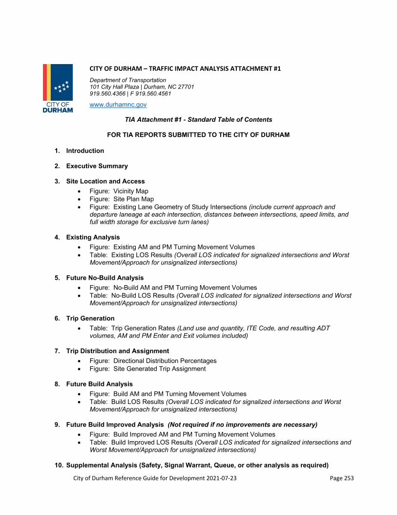
City of Durham Reference Guide for Development 2021‐07‐23 Page 253
CITY OF DURHAM – TRAFFIC IMPACT ANALYSIS ATTACHMENT #1
Department of Transportation 101 City Hall Plaza | Durham, NC 27701 919.560.4366 | F 919.560.4561
www.durhamnc.gov
TIA Attachment #1 - Standard Table of Contents
FOR TIA REPORTS SUBMITTED TO THE CITY OF DURHAM
1. Introduction
2. Executive Summary
3. Site Location and Access
Figure: Vicinity Map Figure: Site Plan Map Figure: Existing Lane Geometry of Study Intersections (include current approach and
departure laneage at each intersection, distances between intersections, speed limits, and full width storage for exclusive turn lanes)
4. Existing Analysis
Figure: Existing AM and PM Turning Movement Volumes Table: Existing LOS Results (Overall LOS indicated for signalized intersections and Worst
Movement/Approach for unsignalized intersections)
5. Future No-Build Analysis
Figure: No-Build AM and PM Turning Movement Volumes Table: No-Build LOS Results (Overall LOS indicated for signalized intersections and Worst
Movement/Approach for unsignalized intersections)
6. Trip Generation
Table: Trip Generation Rates (Land use and quantity, ITE Code, and resulting ADT volumes, AM and PM Enter and Exit volumes included)
7. Trip Distribution and Assignment
Figure: Directional Distribution Percentages Figure: Site Generated Trip Assignment
8. Future Build Analysis
Figure: Build AM and PM Turning Movement Volumes Table: Build LOS Results (Overall LOS indicated for signalized intersections and Worst
Movement/Approach for unsignalized intersections)
9. Future Build Improved Analysis (Not required if no improvements are necessary)
Figure: Build Improved AM and PM Turning Movement Volumes Table: Build Improved LOS Results (Overall LOS indicated for signalized intersections and
Worst Movement/Approach for unsignalized intersections)
10. Supplemental Analysis (Safety, Signal Warrant, Queue, or other analysis as required)
City of Durham Reference Guide for Development 2021‐07‐23 Page 254
11. Findings and Conclusions
Table: LOS Comparison of All Scenarios (Overall LOS indicated for signalized intersections and Worst Movement/Approach for unsignalized intersections)
Figure: Roadway Lane Configurations (Existing, Proposed, and Committed Improvements Indicated, with accompanying identification of parties responsible for improvments)
12. Appendix – Count Data, Trip Generation, LOS Analysis and Output

City of Durham Reference Guide for Development 2021‐07‐23 Page 255
CITY OF DURHAM – TRAFFIC IMPACT ANALYSIS ATTACHMENT #2
Department of Transportation 101 City Hall Plaza | Durham, NC 27701 919.560.4366 | F 919.560.4561
www.durhamnc.gov
TIA Attachment #2 -Traffic Impact Assessment Review Checklist
Development Name: _____________________________________________________ Development Location: ___________________________________________________ Development Owner: _____________________________________________________ TIA Prepared by: _________________ Company: _______________________ Site Plan Prepared by: ______________ Company: _______________________ Review Date: _____________________ Reviewed By: ____________________
Submittal Package:
Full size copy of the site / development plan Plans Sealed TIA Sealed Vicinity map Speed limit(s) of streets within the study area Sketch of traffic distribution percentages Sketch of peak hour volumes Capacity Analyses Signal Warrant Study (if applicable) Documentation of Data and Assumptions (traffic counts, trip generation, safety) Intersection diagrams, including Approach laneage Departure laneage Distance between adjacent intersections Length of full-width storage in existing auxiliary lanes Recommended storage for proposed auxiliary lanes Improvements proposed by developer clearly noted Multi-phase development? Phased improvements addressed? Capacity analysis for phased improvement provided?
General Requirements: Operational analysis performed using Highway Capacity Software / Synchro All project entrances analyzed All signalized intersections within study area analyzed All un-signalized intersections where site traffic will constitute 10% or more of any one approach. Other intersection analysis required?? Which intersection(s): Assumptions: Peak hour factor of 0.9 Type III arrival rate Minimum 6-second yellow + all red clearance 7-second minimum green time per left turn movement 10-second minimum green time per left through movement (speed limit)

City of Durham Reference Guide for Development 2021‐07‐23 Page 256
Scenarios Analyzed: Existing traffic No Build (Existing traffic + 3% annual growth + approved development traffic) Build (Existing traffic + 3% annual growth + approved development traffic + site traffic) Build Improved (Existing + 3% annual growth +approved development traffic+ site traffic+ necessary
improvements)
Detailed Review Comments:
Existing Traffic Volumes: Are the existing counts based on recent peak hour turning movements? If older data were used, have they been updated using reasonable factors (agreed to by the City)? Are the seasonal and day of the week representative of the year or design year? Was construction or any other events that might have impacted the validity of the counts noted? ____________________
Comments: __________________________________________________________________________________________________________________________________________________________________________________________________________________________________________________________________
Trip Generation: Are the project trip generation rates from the latest edition of ITE’s Trip Generation? If yes, are the rates based on a sufficient number of studies to be accurate and used correctly? If local trip generation rates are used, such as from similar developments in the area, is there adequate documentation to support the rates? _________
Comments: __________________________________________________________________________________________________________________________________________________________________________________________________________________________________________________________________
Reduction in Trip Generation: Are any trip reductions used for Pass-By Trips, Internal Capture Traffic, Transit, Ride-Sharing, etc. reasonable? Are reductions adequately documented? Is the source and rationale for reductions valid for this application? Is the full impact of turning movements addressed? ______________________________
Comments: __________________________________________________________________________________________________________________________________________________________________________________________________________________________________________________________________
Trip Distribution / Assignment: Are the expected trip patterns to / from the subject site reasonable based on a market analysis, existing patterns, population distribution, or a network traffic assignment model, etc.? ____________
Comments:
__________________________________________________________________________________________________________________________________________________________________________________________________________________________________________________________________
Background Traffic: Is there a reasonable projection of non-project traffic on the nearby street system for the horizon year based on historic increases and consideration of approved projects in the vicinity? Are these volumes shown graphically? _______________________________________________________________________________
City of Durham Reference Guide for Development 2021‐07‐23 Page 257
Comments: __________________________________________________________________________________________________________________________________________________________________________________________________________________________________________________________________
Analysis: Are the correct time periods evaluated – i.e. AM peak hour, PM peak hour, daily / weekend peaks at shopping centers, recreational uses, etc.? Are levels of service shown for each movement at the study area intersections? Has the study addressed all issues from pre-study meetings / conferences / transmittals, etc.? ________
Comments: __________________________________________________________________________________________________________________________________________________________________________________________________________________________________________________________________
Access: Are the number of driveways proposed the minimum needed to accommodate site traffic? Could conditions be improved with some sort of shared access system or relocation of access points? ___________________________
Comments: __________________________________________________________________________________________________________________________________________________________________________________________________________________________________________________________________
Mitigation Alternatives: If the study acknowledges that improvements to the roadway system will be needed, are the proposed mitigation alternatives reasonable and implementable? ___________________________________________
Comments: __________________________________________________________________________________________________________________________________________________________________________________________________________________________________________________________________
Mitigation Timing: Are the timing and responsibility for implementing mitigation measures addressed sufficiently? Are there any recommended roadway improvements which are not addressed? _______________________________
Comments: __________________________________________________________________________________________________________________________________________________________________________________________________________________________________________________________________
Review Meeting: Is there a need for a joint meeting between the City, community representatives, adjacent communities, others, and the developer to discuss traffic issues related to this project prior to any approval? ________
Comments: __________________________________________________________________________________________________________________________________________________________________________________________________________________________________________________________________
City of Durham Reference Guide for Development 2021‐07‐23 Page 258
Section 11: Standard Notes
This section contains the most commonly used notes and easement phrases. Some of the dimensions are left blank since it is a variable number. Refer to the Durham City/County Zoning Ordinance or the UDO, as applicable, for the requirements of these dimensions.
11.1 Engineering Section Notes
A. Site Plan Standard Notes
Add the notes that apply in the Public Works Special Conditions of Approval box on the cover sheet:
1. The designing professional (a NCPE, NCPLS or NCRLA – as required) shall submit three (3) sets of construction drawings to the Public Works Department – Development Review for review and approval. Construction drawing approval is required prior to commencing construction (see Construction Plan Approval Process). The approval of construction drawings is separate from site plan approval. City officials shall review all sizes, materials, slopes, locations, extensions and depths for all proposed utilities (waterlines, sanitary sewer lines and storm drainage conveyance systems) for compliance with all applicable regulatory standards, specifications, and best management practices.
2. The designing professional (a NCPE, NCPLS or NCRLA – as required) shall submit one (1) set of as-built drawings to the Public Works Department – Development Review for review and approval. As-built drawing approval is required prior to water meter installation and/or sanitary sewer service connection and prior to issuance of a certificate of occupancy.
3. Fire flow analysis required for review and approval as part of the construction drawing approval process. To schedule flow test or to obtain current system data, complete the online application (http://codinetx.durhamnc.gov/sites/PublicWorks/SitePages/FireFlow.aspx).
4. If a meter 2” or larger is proposed, contact Water Management at 560-4381 prior to the construction of the meter vault to verify the type and dimensions of the meter.
5. Water permit required after construction drawing approval and prior to commencing water main installation.
6. Sewer permit required after construction drawing approval and prior to commencing sanitary sewer main installation.
7. Sewer permit from Durham County required. Contact Durham County Utility Division at 560-9033.
8. Pipes and/or structures shown in the Erosion Control Plan of the Site Plan that are proposed to be permanent will be reviewed and approved as part of the Grading Plan during Construction Drawing review. These pipes and/or structures may not be installed prior to Construction Drawing approval and payment of inspection fees.
9. When project has 100 or more units: “A second waterline feed is required prior to the 100th certificate of compliance.”
10. When draining an existing pond: “All road and fill sections that are to be constructed over existing pond features or wetlands will require all unsuitable soils to be excavated and structural road fill to be installed. Special compaction standards will also be required. A licensed geotechnical engineer will be required to provide the necessary analysis. The City of Durham will review and approve the analysis during Construction Drawing review.”
11. An NCDOT or City of Durham Driveway Permit is required.

City of Durham Reference Guide for Development 2021‐07‐23 Page 259
12. Add the following notes when public sidewalk and curb ramps are proposed:
i. PROWAG standards are to be used. See City of Durham Curb Cuts Details http://durhamnc.gov/DocumentCenter/Home/View/2114.
ii. For ramps in ‘tight’ existing developed areas with small ROW’s (Downtown, etc.) it is recommended specific ramp details are needed to prevent construction delays. The burden to make it work is on the designing engineer.
13. If Construction drawings are not required after site plan approval, provide the following notes instead of note 1 above:
i. Provide two (2) sets of approved Site Plan documents to Engineering Inspections, 3rd Floor, 101 City Hall Plaza, Durham, NC 27701 at least 5 days prior to beginning construction and contact Engineering Inspections at 919-560-4326 at least 48 hours prior to beginning construction.
ii. A Construction on City Right-Of-Way / Private Property Permit is required for the proposed [name infrastructure requiring permit]. Contact the Public Works at the Development Services Center at 560-4326.
iii. An encroachment agreement may be required. Contact Engineering Services at 919-560-4326.
B. Easement Notes
1. Water Easement Note
Centerline of _____ foot wide City of Durham Water Easement. Subject to terms stated in the Declaration in Real Estate Book 1510, page 958. No structures, fill, embankments, trees or obstructions permitted within the easement except according to those terms.
2. Sanitary Sewer Easement Note
Centerline of _____ foot wide City of Durham Sanitary Sewer Easement. Subject to terms stated in the Declaration in Real Estate Book 1510, page 958. No structures, fill, embankments, trees or obstructions permitted within the easement except according to those terms.
Centerline of _____ foot wide County of Durham Sanitary Sewer Easement. Subject to terms stated in the Declaration in Real Estate Book 1626, page 145. No structures, fill, embankments, trees or obstructions permitted within the easement except according to those terms.
3. Storm Drainage Easement Note
Centerline of _____ foot wide public storm water drainage easement. Ownership of and responsibility for improvement and maintenance of storm water facilities in this easement remains with the current owner. If the property is within or becomes a part of the City, the easement and access points to the easement are subject to the terms and restrictions stated in the "Revised Declaration of Rights and Privileges of the City of Durham in Storm Water Management Facility Easements" recorded in Real Estate Book 2298, Page 208, which document is incorporated herein. This easement and the Revised Declaration do not create the obligation to provide public maintenance. No building, structures, fills, embankments or obstructions permitted within the easement except according to those terms.
4. Public Access Easement for Sidewalk Note
Certification of Express Dedication for Public Use
City of Durham Reference Guide for Development 2021‐07‐23 Page 260
[Description of the sidewalks to be dedicated inserted here] (“Sidewalks”) are expressly dedicated to use by the general public. Upon construction of the Sidewalks in conformance with all applicable requirements, City Council may accept the Sidewalks for maintenance by the City of Durham (“City”). Acceptance of the Sidewalks by City Council conveys the right in, over, under, and through the Sidewalks, necessary for the City and its agents and contractors, to maintain and repair the sidewalks in the City’s sole discretion. The right of ingress/egress to the Sidewalks from the public right of way is also granted to the City so the City can maintain and repair the sidewalks after acceptance. The City in its sole discretion has the right to determine the points of ingress and egress from the public right of way necessary to perform maintenance or repair after acceptance.
C. Sidewalk Note
The location of the sidewalks shown on this plan is schematic. A City of Durham and/or NCDOT encroachment permit is required prior to any construction. After obtaining the required permits, please contact the City of Durham Engineering Construction Inspection office at 919-560-4326 for a pre-construction conference and field visit prior to any work on the proposed sidewalk.
D. Townhome Note (Private Access and Common Areas)
The driving and parking areas shown on this Final Plat noted as “Private Access and Common Areas” do not meet City of Durham street standards. The features and infrastructure within these areas are private and will never be eligible for public maintenance. [Insert subdivision name] Homeowner’s Association and its members will own and be responsible for the maintenance and repair of the Private Access and Common Areas and all of the private infrastructure within them (water, sewer, storm, pavement, sidewalks, curb, etc.).
E. Utility Notes
1. Water Service Abandonment
Abandonment of water services shall include excavating down to corporation stop, turning it off and cutting service line free from corporation stop. The meter, if present, shall be returned to City of Durham. Prior to any credit or refund being processed the meter must be returned to Water Management Department and the meter number verified and coded properly as returned. Utility Service Abandonments will take place prior to beginning utility construction work for a project. Any excavation as part of abandoning utilities will require backfilling per City of Durham standards.
2. Sanitary Sewer Abandonment
Abandonment of sanitary sewer service lines shall consist of excavating down to the service connection to the main, cutting this connection and installing a watertight plug in the main. The service line and all clean-out risers on the service line shall be removed. Utility Service Abandonments will take place prior to beginning utility construction work for a project. Any excavation as part of abandoning utilities will require backfilling per City of Durham standards.
3. Horizontal and Vertical Separation
Sanitary Sewers shall be laid at least 10-feet horizontally from any existing or proposed water main. The distance shall be measured edge to edge. In cases where it is not practical to maintain a 10-foot separation, the City of Durham may allow deviation on a case-by-case basis, if supported by data from the design engineer. Such deviation on may allow the installation of the sanitary sewer

City of Durham Reference Guide for Development 2021‐07‐23 Page 261
closer to a water main, provided that the water main is in a separate trench or on an undisturbed earth shelf located on one side of the sanitary sewer and at an elevation so the bottom of the water main is at least 18-inches above the top of the sewer.
If it is impossible to obtain proper horizontal and vertical separation as described above or anytime the sanitary sewer is over the water main, both the water main and sanitary sewer must be constructed of ferrous pipe complying with the public water supply design standards and be pressure tested to 150-psi to assure water tightness before backfilling.
A 18-inch vertical separation shall be provided between storm sewer and sanitary sewer lines or ferrous pipe specified. A 12-inch vertical separation shall be provided between storm sewer and water mains.
o If a 12-inch vertical separation is not maintained at a crossing between storm sewer and water mains (or pressure sewers). The water main shall be constructed of ferrous pipe and a concrete collar shall be poured around water mains and storm sewer to immobilize the crossing.
4. Crossings
Sanitary Sewer crossing water mains shall be laid to provide a minimum vertical distance of 18-inches between the outside of the water main and the outside of the sanitary sewer. The crossing shall be arranged so that the sanitary sewer joints will be equidistant and as far as possible from the water main joints.
When it is impossible to obtain proper horizontal and vertical separation as stipulated above, one of the following methods must be specified. o The sanitary sewer shall be designed and constructed of ferrous pipe and shall be pressure
tested at 150-psi to assure water tightness prior to backfilling, or o Either the water main or the sanitary sewer line may be encased in a watertight carrier pipe,
which extends 10-feet on both sides of the crossing, measured perpendicular to the water main. The carrier pipe shall be of materials approved by the City of Durham for use in water main construction.
F. Driveway Permit
A City of Durham Driveway Permit is required prior to any driveway construction on public right-of-way. Submit plans for Driveway Permit approval to City Engineering Development Review. After obtaining the permit, please call City of Durham Engineering Inspection office at 919-560-4326 prior to start of construction.
NCDOT Driveway Permit required prior to construction. Contact NCDOT at 919-220-4750 for requirements.
G. Utilities Note
Provide Utility Crossing Construction note where there are new mainline (public or private) utilities proposed on plans as follows: “A Utility Mainline Construction permit is required prior to the installation of each utility. All utilities shall submit plan drawings and applications to the City Engineering Division.”
City of Durham Reference Guide for Development 2021‐07‐23 Page 262
11.2 Stormwater Services Notes
A. Site Plan Notes
The following notes shall be included in the Public Works Conditions of Approval box on the cover sheet for Site Plan/Preliminary Plat submittals. These notes may or may not apply to the project depending on the requirements of the project (to be determined by designer and during review).
At a minimum, the stormwater design details for this project shall be governed by the minimum standards of the most recent edition of the City of Durham (City) Reference Guide for Development (RGD) and any Letters to Industry (posted on the City’s website) that are in effect the date Construction Drawings are first received for review by the City.
Final design calculations for the stormwater control measure(s) (SCM[s]) require the use of storage indication routing methodology such as TR-20 or HEC-1 models. For each SCM, as applicable, stage-storage relationship and inflow and outflow hydrographs are required. All tabulated data including calculations showing the limiting discharge, whether orifice, weir, barrel, or outlet control, as appropriate is required. HydroCad, Hydraflow Hydrographs, and PondPack are commonly used and recognized software programs which incorporate routing methodology accepted by the City.
Use for residential developments with a Homeowners Association:
Stormwater control measure(s) (SCM[s]) permit fee(s) and a payment into the Stormwater Replacement Fund are required for all SCM(s) associated with this development. Construction of the development is not allowed to commence until these items are provided in accordance with City Stormwater Standards or in accordance with written policy. The designer shall submit a sealed engineer’s construction cost estimate for every SCM proposed in the development prior to approval of the construction drawings.
Use for Multi-family and other type developments:
Stormwater control measure(s) (SCM[s]) permit fee(s) and either a payment into the Stormwater Replacement Fund or the provision of an alternate security are required for all SCM(s) associated with this development. Construction of the development is not allowed to commence until these items are provided in accordance with City Stormwater Standards or in accordance with written policy. The designer shall submit a sealed engineer’s construction cost estimate for every SCM proposed in the development prior to approval of the construction drawings.
An as-built certification for the stormwater control measure(s) (SCM[s]), provided by the certifying engineer, is required. The as-built certification shall be submitted in accordance with the City of Durham SCM As-built Program, refer to Section 8.6, As-built Certification Requirements for SCMs in the City of Durham, of the Reference Guide for Development. The SCM as-built certification(s) shall be approved by the Stormwater Development Review Section prior to issuance of any final certificates of occupancy/compliance for development, with the exception of when an appropriate construction security has been provided for single family or townhome development. With this provided construction security, certificates of occupancy/compliance can be issued for a percentage of single family lots in accordance with City requirements.
Stormwater control measure(s) (SCM[s]) design calculations will not be reviewed or approved with the Site Plan/Preliminary Plat submittal. All SCM designs will be reviewed and approved during the construction drawing submittal process. If, at the time of construction drawing submittal, it is found that the proposed SCM(s) is undersized, not properly accessible, or otherwise insufficient or unsuitable for the site, it is the responsibility of the applicant to insure that the applicable stormwater
City of Durham Reference Guide for Development 2021‐07‐23 Page 263
ordinance requirements are met. A revised site plan or preliminary plat may be required if the originally proposed SCM(s) are found insufficient, not properly accessible, or unsuitable and alternative SCM(s) with associated easements are required.
The Developer/Contractor shall schedule a pre-construction meeting with the Stormwater Development Review section prior to commencing work on any Stormwater Control Measure (SCM). If the SCM will be constructed initially as a Sedimentation and Erosion Control (S&EC) device, to be converted to a permanent SCM at a later time, the pre-construction meeting should be scheduled prior to construction of the S&EC device. Call 919-560-4326 Ext. 30238 to schedule the required meeting a minimum of three business days prior to the desired meeting date. This is in addition to other pre-construction meeting requirements for erosion control, engineering inspections, etc.
Use for Single Family Detached, Townhome and Duplex Residential Developments making use of a nutrient bank and/or the North Carolina Division of Mitigation Services (NC Ecosystem Enhancement Program) when insufficient credits are available from the nutrient banks:
To receive construction drawings approval for Single Family Detached, Townhome and Duplex Residential Developments that are making use of nutrient banks and/or the NCEEP, the approval of the construction drawings is contingent upon the purchase of nutrient credits. If a revised site plan/preliminary plat is submitted for this site, the revised site plan/preliminary plat will be subject to any ordinances in place at the time of the revised site plan/preliminary plat submission. Prior to the approval of any construction drawings or prior to the release of any building permits pertaining to this development, whichever comes first, a letter/receipt showing the purchase of the nutrient credits for this development and a copy of the nutrient bank ledger if applicable, showing the total nutrient credits available minus any and all deductions, is to be provided to the Stormwater Development Review Section. However, if insufficient credits are available from nutrient banks and NCEEP will not accept payment, then the applicant shall submit a revised site plan/preliminary plat back to the Durham City-County Planning Department and shall comply with the current Stormwater Performance Standards in place at the time of the revised site plan/preliminary plat submission.
Use for developments other than Single Family Detached, Townhome and Duplex Residential Developments making use of a nutrient bank and/or the North Carolina Division of Mitigation Services (NC Ecosystem Enhancement Program) when insufficient credits are available from the nutrient banks:
To receive site plan/preliminary plat approval for developments other than Single Family Detached, Townhome and Duplex Residential Developments that are making use of nutrient banks or NCEEP, the approval of the site plan/preliminary plat is contingent upon the purchase of nutrient credits. If a revised site plan/preliminary plat is submitted for this development, the revised site plan/preliminary plat will be subject to any ordinances in place at the time of the revised site plan/preliminary plat submission. Prior to the approval of the site plan/preliminary plat, a letter/receipt showing the purchase of the nutrient credits for this development and a copy of the nutrient bank ledger if applicable, showing the total nutrient credits available minus any and all deductions, is to be provided to the Stormwater Development Review Section.
B. Construction Drawings Notes
The following notes shall be included on the cover sheet for Construction Drawings submittals. These notes may or may not apply to the project depending on the requirements of the project (to be determined by the designer and during review).

City of Durham Reference Guide for Development 2021‐07‐23 Page 264
At a minimum, the stormwater design details for this project shall be governed by the minimum standards of the most recent edition of the City of Durham (City) Reference Guide for Development (RGD) and any Letters to Industry (posted on the City’s website) that are in effect the date Construction Drawings are first received for review by the City.
Final design calculations for the stormwater control measure(s) (SCM[s]) require the use of storage indication routing methodology such as TR-20 or HEC-1 models. For each SCM, as applicable, stage-storage relationship and inflow and outflow hydrographs are required. All tabulated data including calculations showing the limiting discharge, whether orifice, weir, barrel, or outlet control, as appropriate is required. HydroCad, Hydraflow Hydrographs, and PondPack are commonly used and recognized software programs which incorporate routing methodology accepted by the City.
Stormwater control measure(s) (SCM[s]) permit fee(s) and either payment into the Stormwater Replacement Fund or the provision of an alternate security is required for all SCMs associated with this development. Construction of the development is not allowed to commence until these items are provided in accordance with City Stormwater Standards. The designer shall submit a sealed engineer’s construction cost estimate for each SCM proposed in the development prior to approval of the construction drawings. Note that the Stormwater Replacement Fund is the only financial guarantee option for residential developments with a homeowners association.
An as-built certification for the stormwater control measure(s) (SCM[s]), provided by the certifying engineer, is required. The as-built certification shall be submitted in accordance with the City of Durham SCM As-built Program, refer to Section 8.6, As-built Certification Requirements for SCMs in the City of Durham, of the Reference Guide for Development. The SCM as-built certification(s) shall be approved by the Stormwater Development Review Section prior to issuance of any final certificates of occupancy/compliance for development, with the exception of when an appropriate construction security has been provided for single family or townhome development. With this provided construction security, certificates of occupancy/compliance can be issued for a percentage of single family lots in accordance with City requirements.
The Developer/Contractor shall schedule a pre-construction meeting with the Stormwater Development Review section prior to commencing work on any Stormwater Control Measure (SCM). If the SCM will be constructed initially as a Sedimentation and Erosion Control (S&EC) device, to be converted to a permanent SCM at a later time, the pre-construction meeting should be scheduled prior to construction of the S&EC device. Call 919-560-4326 Ext. 30238 to schedule the required meeting a minimum of three (3) business days prior to the desired meeting date. This is in addition to other pre-construction meeting requirements for erosion control, engineering inspections, etc.
C. Final Plat Notes
The following notes shall be included on Final Plats. These notes may or may not apply to the project depending on the requirements of the project (to be determined by applicant and during review).
Restrictive covenants note(s) required per the final plat checklist for residential developments with a HOA:
THE “COMMON ELEMENTS” AND/OR “OPEN SPACES” EXPRESSLY ARE DEDICATED HEREBY FOR THE USE AND ENJOYMENT OF THE HOMEOWNERS IN (ENTER NAME OF DEVELOPMENT) AND ARE TO BE CONVEYED BY (ENTER OWNER NAME) TO (ENTER HOMEOWNER ASSOCIATION NAME), AS MORE FULLY PROVIDED IN THE DECLARATION OF COVENANTS, CONDITIONS, AND RESTRICTIONS APPLICABLE TO (ENTER NAME OF DEVELOPMENT) DATED ___________ AND RECORDED IN BOOK ______, PAGES ______ , IN THE DURHAM COUNTY REGISTRY, AS AMENDED FOR THIS AND FUTURE SECTIONS AND

City of Durham Reference Guide for Development 2021‐07‐23 Page 265
MAPS, SAID DECLARATION BEING HEREBY INCORPORATED AND MADE A PART OF THIS PLAT.
STORMWATER FACILITY RESPONSIBILITY: THE (ENTER HOMEOWNER ASSOCIATION NAME) SHALL BE RESPONSIBLE FOR MAINTAINING THE COMPLETED PERMANENT STORMWATER FACILITY(IES) IN ACCORDANCE WITH THE OPERATION AND MAINTENANCE MANUAL(S) OR AS DIRECTED BY THE GOVERNEMENT OFFICE HAVING JURISDICTION FOR STORMWATER PERFORMANCE STANDARDS AND, IF THE OWNER’S ASSOCIATION SHOULD BE DISSOLVED OR CEASE TO EXIST, THEN IN THAT EVENT THE OWNERS OF RECORD AT THE TIME OF REQUIRED MAINTENANCE SHALL BE JOINTLY AND SEVERALLY LIABLE FOR ANY AND ALL COSTS ATTENDANT THERETO.
Easement note per the final plat checklist for developments without an HOA:
THE OPERATION, MAINTENANCE, AND RECONSTRUCTION RESPONSIBILITY OF THE STORMWATER CONTROL MEASURE(S) (SCM[s]) LOCATED WITHIN THE SCM ACCESS & MAINTENANCE EASEMENT RESTS WITH THE OWNER PER SECTION 70-743 OF THE DURHAM CITY CODE. THE SCM ACCESS & MAINTENANCE EASEMENT GRANTS THE CITY OF DURHAM AND THEIR ASSIGNS RIGHT OF ACCESS TO THE PERMANENT STORMWATER CONTROL MEASURE(S) FOR INSPECTIONS AND ENFORCEMENT OF OPERATION & MAINTENANCE. NO OBSTRUCTION SHALL BE ALLOWED IN THE EASEMENT WHICH COULD IMPEDE NECESSARY MAINTENANCE BY THE OWNER AND ANY ENFORCEMENT BY THE CITY.
Easement note per the final plat checklist for developments with an HOA:
THE STORMWATER CONTROL MEASURE (SCM) ACCESS & MAINTENANCE EASEMENT GRANTS THE CITY OF DURHAM AND THEIR ASSIGNS RIGHT OF ACCESS TO THE PERMANENT STORMWATER CONTROL MEASURE(S) FOR INSPECTIONS AND ENFORCEMENT OF OPERATION & MAINTENANCE. NO OBSTRUCTION SHALL BE ALLOWED IN THE EASEMENT WHICH COULD IMPEDE NECESSARY MAINTENANCE BY THE OWNER OR ENFORCEMENT BY THE CITY.
Optional blanket easement for multi-family and other development (cannot be used for limited residential):
THE CITY OF DURHAM AND THEIR ASSIGNS HAVE RIGHT OF ACCESS TO THE PERMANENT STORMWATER CONTROL MEASURE(S) (ENTER TYPE(S)) FOR INSPECTIONS AND MAINTENANCE ENFORCEMENT. A BLANKET ACCESS EASEMENT TO, OVER AND AROUND THE STORMWATER CONTROL MEASURE IS HEREBY GRANTED FOR INSPECTIONS AS WELL AS ENFORCEMENT OF OPERATION & MAINTENANCE. ANY OBSTRUCTION PLACED IN THE BLANKET EASEMENT THAT IMPEDES NECESSARY MAINTENANCE ENFORCEMENT WILL BE REMOVED AND ALL THE ASSOCIATED COSTS WILL BE BORNE SOLEY BY THE OWNER.
11.3 Department of Transportation Notes
A. Sidewalk
The location of the sidewalk shown on this plan is schematic. A City of Durham and /or NCDOT encroachment permit is required prior to any construction. After obtaining the required permits,

City of Durham Reference Guide for Development 2021‐07‐23 Page 266
please contact the City of Durham Engineering Construction Inspection office at 560-4326 for a pre-construction conference and field visit prior to any work on the proposed sidewalk.
Prior to the issuance of a certificate of occupancy, make a payment in lieu fee to the City of Durham through the Public Works Department in the amount of $________ (___LF x $65.00/LF).
If project doesn’t propose a building (example: parking lot only) then the payment in lieu fee shall be paid before site plan approval.
B. Off‐site Roadway Improvements
Add the following note to the special conditions of approval box:
By referencing roadway improvements on the plan, the applicant agrees to construct said improvements prior to issuance of certificate of occupancy in a manner that will allow them to function as noted on the plan and in accordance with NCDOT and City of Durham standards and policies. This includes (where appropriate) but is not limited to: adequate transition tapers, alignment of lanes through intersections, associated signal modifications, pavement markings, associated signage, curb and gutter, coordination with other proposed roadway improvements and bike lanes. The applicant also accepts the financial responsibility for acquisition of any additional right-of-way necessary to accommodate these improvements and any required sidewalk construction.
All off-site roadway improvements must be complete prior to the issuance of any certificate of occupancy.
C. Signs and/or Pavement Markings
When signs and/or pavement markings are to be installed by the developer (new subdivisions or off-site roadway improvements that need new markings for example), add the following note to the special conditions of approval box:
The developer is responsible for fabrication and installation of all required standard street name signs, traffic control signs, poles, and pavement markings within the public right-of-way. The developer shall submit a signing and markings plan to the City at construction plan stage for review and approval. All signs and pavement markings, shown on the construction plans, must be in place prior to the issuance of any certificate of occupancy. The developer will maintain the signs, poles, and markings until the street is accepted by the City of Durham, where from there, the City or NCDOT will maintain the signs, poles, and markings at no additional cost to the developer.
D. Right of Way Dedication
When dedicating right of way on a major/minor thoroughfare adjacent to the site, add the following note to the special conditions of approval box:
Dedicate an additional ___ feet of right-of-way along the frontage of the site on _________ Road prior to the issuance of any building permit. A copy of the recorded plat must be submitted with the first building permit application.

City of Durham Reference Guide for Development 2021‐07‐23 Page 267
E. Bus Stop/Shelter
When a bus stop/shelter is to be constructed near the site, add the following note to the special conditions of approval box:
Provide bus shelter with concrete pad on ______ Road. Design specifications and exact location to be reviewed and approved by DATA prior to construction.
F. Where Streets Terminate
Where streets terminate (example Phase lines) the following will be installed: 1) Asphalt header, 2) Riprap or concrete apron for storm water to dissipate, 3) Utilities to extend a minimum of 5-feet beyond the edge of pavement, 4) NCDOT type III barricade.
G. Signage and Marking Plan Construction Drawing Note
All signs, street markers, and pavement markings (everything called out on the signing and marking sheet) must be installed on each street prior to the issuance of a certificate of occupancy and/or street acceptance, as determined by the City.
The street name sign shall be reflective to show the same shape and similar color both day and night. The letters and background shall be of contrasting colors.
Street name signs shall have white letters on a green background.
Lettering on the street names shall be 4-inches high in capital letters.
Suffix lettering to indicate the type of street (such as street, avenue, or road) or the section of the City (such as NW) shall be lettering 2-inches high.
Street name signs will be located on top of stop signs in a stacked position.
Stop bars shall be 2-feet wide white thermoplastic per NCDOT specifications.
All signs must conform with the Manual On Uniform Traffic Control Devices (MUTCD).
Street signs shall show block numbers. (Block numbers are shown on the recorded plat. If they are not shown on recorded plat, contact the City’s Engineering Assessments Division at 560-4326)

City of Durham Reference Guide for Development 2021‐07‐23 Page 268
Section 12: Forms
The forms can be found at the Public Work’s website:
http://durhamnc.gov/985/Forms-Applications
http://durhamnc.gov/2988/Forms-and-Templates (Stormwater Securities and SCM Forms and Templates).

City of Durham Reference Guide for Development 2021‐07‐23 Page 269
Section 13: Development Fees
This section is intended to aid in the process of determining the fees from the Engineering and Stormwater & GIS Divisions that may be associated with a project. The fees are subject to change without notification.
13.1 Water and Sanitary Sewer Charges
A. Due Diligence Property Information
The fee for obtaining water and sewer service information from Engineering Services is $20.
B. Summary Utility Development Statement
A Summary Utility Development Statement (SUDS) from the Department of Water Management is required for all projects requiring annexation and rezoning. Single-family homes, duplexes, triplexes and Accessory Dwelling Units (ADU)s that are submitted individually and not as part of a larger development are exempt from this fee and may not require a SUDS.
Summary Utility Development Statement fee = $500 (fffective September 1, 2021). Application: https://durhamnc.gov/FormCenter/Water-Management-16/Required-Utilities-Statement-Application-173
C. Utility Extension Agreement
The extension agreement application fee is (includes technology fee):
$520 for development projects $104 for one single-family residence
D. Frontage Charges
These fees are applicable when property is developed and a water and/or sanitary sewer line has not been installed by the developer or property owner across the street frontage or street right-of-way abutting the project. These fees are paid when the mains are extended for new projects. If no extension is made frontage charges are paid with the application for service. These are effective since May 1, 2010.
The current frontage charges are: Water Sanitary Sewer Inside City Limits $27.00/LF $50.00/LF Outside City Limits $29.50/LF $56.00/LF
E. Capital Facility Fees
F. These fees are due prior to connection. Typically, these fees are paid with the application for the service connection. The fees below are required per Section 70.50 of the Ordinance and shall be in full force and effect of July 1, 2018. The current capital facilities fees are:
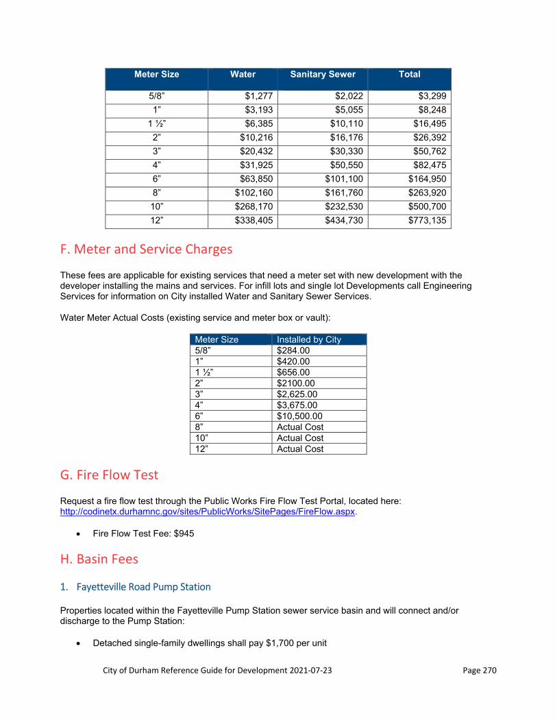
City of Durham Reference Guide for Development 2021‐07‐23 Page 270
Meter Size Water Sanitary Sewer Total
5/8” $1,277 $2,022 $3,299
1” $3,193 $5,055 $8,248
1 ½” $6,385 $10,110 $16,495
2” $10,216 $16,176 $26,392
3” $20,432 $30,330 $50,762
4” $31,925 $50,550 $82,475
6” $63,850 $101,100 $164,950
8” $102,160 $161,760 $263,920
10” $268,170 $232,530 $500,700
12” $338,405 $434,730 $773,135
F. Meter and Service Charges
These fees are applicable for existing services that need a meter set with new development with the developer installing the mains and services. For infill lots and single lot Developments call Engineering Services for information on City installed Water and Sanitary Sewer Services.
Water Meter Actual Costs (existing service and meter box or vault):
Meter Size Installed by City 5/8” $284.00 1” $420.00 1 ½” $656.00 2” $2100.00 3” $2,625.00 4” $3,675.00 6” $10,500.00 8” Actual Cost 10” Actual Cost 12” Actual Cost
G. Fire Flow Test
Request a fire flow test through the Public Works Fire Flow Test Portal, located here: http://codinetx.durhamnc.gov/sites/PublicWorks/SitePages/FireFlow.aspx.
Fire Flow Test Fee: $945
H. Basin Fees
1. Fayetteville Road Pump Station
Properties located within the Fayetteville Pump Station sewer service basin and will connect and/or discharge to the Pump Station:
Detached single-family dwellings shall pay $1,700 per unit
City of Durham Reference Guide for Development 2021‐07‐23 Page 271
Other uses other than single family dwellings, such as multi-family and nonresidential development, shall pay up to $4.75 per gallon of permitted wastewater flow
2. Del Web Pump Station
Properties located within the Del Webb Pump Station sewer service basin and will connect and/or discharge to the Del Webb Sewer Pump Station:
Detached single-family (includes condominium-style townhomes and townhomes) dwellings shall pay $2,500.00 per unit
Other uses than single family dwellings, such as multi-family and nonresidential development, shall pay up to $11.57 per gallon of permitted wastewater flow
3. Southeast Regional Pump Station
Properties located within the Service Area for the Southeast Regional Lift Station shall pay the following Service Area Fees (as of July 2021):
Single Family Residence $5,708.80/unit Multi-Family and Non-Residential $15.87/Gallon of Average Daily Flow
This Service Area Fee shall increase 5% annually effective July 1 of each year. Payment of Service Area Fees shall be made at the time the sewer collection lines are permitted for construction. Payment of the Service Area Fee does not guarantee that said infrastructure shall be available by any particular date.
4. Farrington Road Waterline
Properties located within the Service Area for the Farrington Road Waterline shall pay the following Service Area Fees (as of July 2021):
Residential Unit $458.39 Non- Residential Unit, rate per gallon of average daily flow $1.28
The fees stated in Part 15-103 (d) shall increase 5%, compounding annually effective July 1 of each year, with the first annual increase occurring on July 1, 2018. The rates shall be rounded up to the nearest cent with each increase.
5. Copley Farms Sewer Outfall
Properties located within the Service Area for the Copley Farms Sewer Outfall shall pay the following Service Area Fees (as of July 2021):
Residential Unit $1,015.40 Non- Residential Unit, rate per gallon of average daily flow $2.82
The fees stated in Part 15-103 (d) shall increase 5%, compounding annually effective July 1 of each year, with the first annual increase occurring on July 1, 2020. The rates shall be rounded up to the nearest cent with each increase.

City of Durham Reference Guide for Development 2021‐07‐23 Page 272
6. Andrews Chapel Pump Station
Properties located within the Andrews Chapel Pump Station sewer service basin and will connect and/or discharge to the Andrews Chapel Sewer Pump Station:
Detached single-family (includes condominium-style townhomes and townhomes) dwellings shall pay $1,406.00 per unit
Other uses than single family dwellings, such as multi-family and nonresidential development, shall pay up to $3.91 per gallon of permitted wastewater flow
13.2 Other Permits and Fees
Effective July 1, 2020 the following fees will apply:
A. Building Permit Review Fee
Public Works Residential Building Permit Plan Review: $104 Public Works Commercial or Retaining Wall Building Permit Plan Review: $208
B. Construction Drawing Review Fee
Construction drawings review fees plus a 4% technology surcharge fee shall be paid at time of the initial submittal. Base fee below applies per phase of project plans (ie if a 3 phase project is submitted the fee is 3x the base fee plus lot fees if lot fees apply). Phasing any type of project after construction drawing approval will result in a base fee charge per phase only.
Type of Project Base Fee (per phase)
Commercial Construction Drawings not requiring any water/sewer permits $1,500 Commercial or Apartments Construction Drawings requiring water and/or sewer permits
$2,500 + $500 per additional apartment building
Single-Family and/or Townhome Subdivision Construction Drawings $2,500 + $25/lot Other construction drawings review fees are listed below. The fees plus a 4% technology surcharge fee shall be paid at time of the initial submittal.
Type of Project Base Fee (per phase)
Construction Drawings field change $200 Construction Drawings revision $1,000 Pump Station Construction Drawings $10,000
C. Extension Permits Fees
Water Extension Permit Fee: $450 Sewer Extension Permit Fee: $450
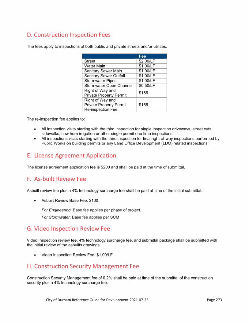
City of Durham Reference Guide for Development 2021‐07‐23 Page 273
D. Construction Inspection Fees
The fees apply to inspections of both public and private streets and/or utilities.
Fee Street $2.00/LF Water Main $1.00/LF Sanitary Sewer Main $1.00/LF Sanitary Sewer Outfall $1.00/LF Stormwater Pipes $1.00/LF Stormwater Open Channel $0.50/LF Right of Way and Private Property Permit
$156
Right of Way and Private Property Permit Re-inspection Fee
$156
The re-inspection fee applies to:
All inspection visits starting with the third inspection for single inspection driveways, street cuts, sidewalks, cow horn irrigation or other single permit one time inspections.
All inspections visits starting with the third inspection for final right-of-way inspections performed by Public Works on building permits or any Land Office Development (LDO) related inspections.
E. License Agreement Application
The license agreement application fee is $200 and shall be paid at the time of submittal.
F. As‐built Review Fee
Asbuilt review fee plus a 4% technology surcharge fee shall be paid at time of the initial submittal.
Asbuilt Review Base Fee: $100
For Engineering: Base fee applies per phase of project.
For Stormwater: Base fee applies per SCM
G. Video Inspection Review Fee
Video Inspection review fee, 4% technology surcharge fee, and submittal package shall be submitted with the initial review of the asbuilts drawings.
Video Inspection Review Fee: $1.00/LF
H. Construction Security Management Fee
Construction Security Management fee of 0.2% shall be paid at time of the submittal of the construction security plus a 4% technology surcharge fee.
City of Durham Reference Guide for Development 2021‐07‐23 Page 274
Construction Security Management fee: 0.2% of the amount of the construction security issued ($100 minimum) plus 4% technology surcharge fee based on the amount of the Construction Security Management fee.
I. Stormwater Control Measure Financial Guarantees
Perpetual Surety and Replacement Fund Payments are determined by the Stormwater Development Review Section based upon written policy which equates to amounts of 20 times the annual SCM maintenance costs or 25% of the SCM construction costs, respectively. The construction security management fee of 0.2% and the 4% technology surcharge fee does not apply to SCM financial guarantees.
City of Durham Reference Guide for Development 2021‐07‐23 Page 275
APPENDIX A: Procedure for Obtaining a Copy of the
Published NRCS Soil Surveys for NC

City of Durham Reference Guide for Development 2021‐07‐23 Page 276
This page intentionally left blank.

City of Durham Reference Guide for Development 2021‐07‐23 Page 277
2-WI-42a Hydrologic Soil Groups
The hydrologic soil group classifications shown in Table 2‐1 on pages 2‐42 through 2‐83 are obsolete and
should not be used. Hydrologic soil group classifications can vary by location. Soils with the same map
unit name, but located in different counties, may have different hydrologic soil group classifications.
Current hydrologic soil group classifications (ratings) for the applicable county should be obtained from
the NRCS Web Soil Survey as shown below.
Retrieving Hydrologic Soil Group Data from the NRCS Web Soil Survey:
Navigate to the NRCS web soil survey: http://websoilsurvey.nrcs.usda.gov/app/
(or Google NRCS Web Soil Survey)
Select the Green “Start WSS” Button:
On the left side of the screen navigate to and select “Soil Survey Area”:
Make State selection. Make County selection and click radial button next to the applicable County. Or
just select the radial button next to the applicable County (if needed, scroll down to find County):
Or:
EFH Notice 210‐WI‐132
January 2015

City of Durham Reference Guide for Development 2021‐07‐23 Page 278
2‐WI‐42b
Select “Set AOI” (either at the top or the bottom of the Soil Survey Area Section):
Select “Select Map Units” (either at the top or the bottom of the Soil Survey Area Section):
Check the box(es) next to the applicable Map Units, or click on “Select All”:
EFH Notice 210‐WI‐132
January 2015

City of Durham Reference Guide for Development 2021‐07‐23 Page 279
2‐WI‐42b
Click on the “Soil Data Explorer” Tab near the top of the screen:
Click on the “Soil Properties and Qualities” Tab, located below the Soil Data Explorer Tab.
Then, navigate to the left side of the screen and select “Soil Qualities and Features”:
Select “Hydrologic Soil Group”:
EFH Notice 210‐WI‐132
January 2015
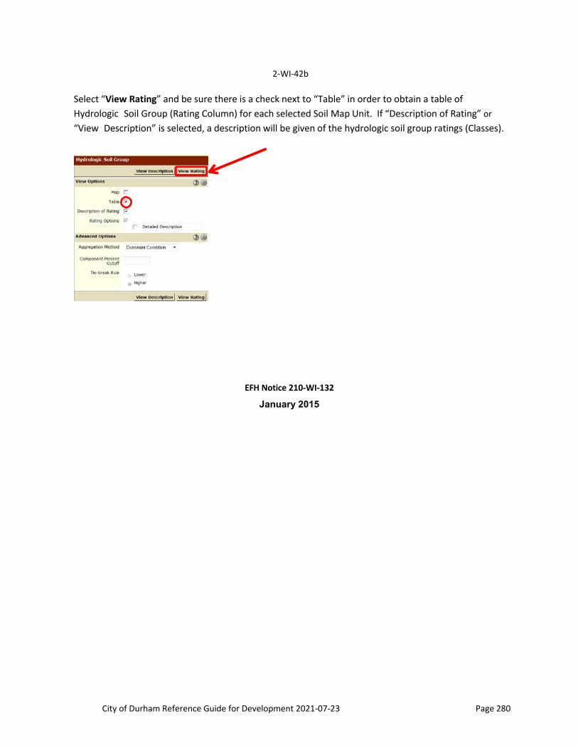
City of Durham Reference Guide for Development 2021‐07‐23 Page 280
2‐WI‐42b
Select “View Rating” and be sure there is a check next to “Table” in order to obtain a table of
Hydrologic Soil Group (Rating Column) for each selected Soil Map Unit. If “Description of Rating” or
“View Description” is selected, a description will be given of the hydrologic soil group ratings (Classes).
EFH Notice 210‐WI‐132
January 2015