reference electrodes for monitoring cathodic protection …€¦ · when cathodic protection...
TRANSCRIPT

Page 1 of 32
CEOCOR Commission 2 Reference Electrodes BSW SF MB DC FB Rev 11 221118 Final Approved © CEOCOR
REFERENCE ELECTRODES FOR MONITORING CATHODIC PROTECTION ON BURIED PIPELINES
PRE-STANDARD: CEOCOR WORKING GROUP PUBLICATION
CEOCOR Commission 2 External Corrosion and Cathodic Protection Working Group E Chaired by Brian S Wyatt: Corrosion Control, UK Rev11: Approved by WG E and CEOCOR Board Brussels November 2018

Page 2 of 32
CEOCOR Commission 2 Reference Electrodes BSW SF MB DC FB Rev 11 221118 Final Approved © CEOCOR
TABLE OF CONTENTS
Page Table of Contents.......................................................................................................... 2 1.0 Scope.................................................................................................... 3 2.0 Normative references and terms………............................................. 3 3.0 Definition and Types of Reference Electrodes................................. 5 4.0 Permanent Reference Electrodes………………………………………17 5.0 Portable Reference Electrodes ……………………………………...... 20 6. 0 Reference Electrode Parameters: Permanently Installed................21 7.0 Reference Electrode Parameters: Portable...................................... 23 8.0 Installation Procedures for Permanent Reference Electrodes....... 24 9.0 Pre-Commissioning and Commissioning Procedures.................... 26 Appendix A 26 Possible Scheme for Control/Calibration of Reference Electrodes Appendix B 30 Target values for Maximum Agreed Errors (MAEs) and Parameters as Basis
of Purchase Specification

Page 3 of 32
CEOCOR Commission 2 Reference Electrodes BSW SF MB DC FB Rev 11 221118 Final Approved © CEOCOR
1.0 Scope This technical recommendation has been prepared by CEOCOR Working Group members and defines minimum requirements for both fixed (permanently installed) and portable reference electrodes used for cathodic protection (CP) monitoring purposes for buried onshore pipelines. It defines accuracy requirements, calibration, testing and installation of reference electrodes for this application. Reference electrodes are essential for monitoring the cathodic protection effectiveness as defined in EN ISO 15589-1, EN ISO 12696, EN 12954, EN 13509, EN 13636, EN ISO 15257, EN 15280, EN 50162, EN 50443, EN 14505, EN ISO 18086. There is a range of reference electrodes with different electrode potentials; it is essential that when pipe/soil potentials are measured and reported that which reference electrode and which voltmeter are used are recorded. Without such a record the value recorded has no meaning. 2.0 Normative references EN ISO 15589-1: Petroleum and natural gas industries – Cathodic protection of pipeline transportation systems – Part 1: Onshore pipelines EN ISO 12696: Cathodic protection of steel in concrete EN 12954: Cathodic protection of buried or immersed metallic structures – General principles and application for pipelines (in process of being replaced with a revision of ISO 15589-1) EN 13509: Cathodic protection measurement techniques EN 13636: Cathodic protection of buried metallic tanks and related piping EN ISO 15257: Cathodic Protection – Competence levels of cathodic protection persons – Basis for certification scheme EN 15280: Evaluation of a.c. corrosion likelihood of buried pipelines applicable to cathodically protected pipelines EN 50162: Protection against corrosion by stray current from direct current systems EN 50443: Effects of electromagnetic interference on pipelines caused by high voltage a.c. electric traction systems and/or high voltage a.c. power supply systems EN 14505: Cathodic Protection of Complex Structures EN ISO 18086 Corrosion of metals and alloys – Determination of AC corrosion – Protection criteria ISO EN 10012: Measurement management systems — Requirements for measurement processes and measuring equipment Although not a Normative reference, there is a CEOCOR recommendation for Coupons: ‘Application of Coupons and Probes for Cathodic Protection Monitoring Purposes’ which was completed in CEOCOR Commission 2 WG B in April 2013.

Page 4 of 32
CEOCOR Commission 2 Reference Electrodes BSW SF MB DC FB Rev 11 221118 Final Approved © CEOCOR
This is available from the CEOCOR web site1. The terms and symbols used in this Document correspond to those used in EN 12954 and EN 13509, with the exception that the ENs refer to copper/saturated copper sulphate and this document (to be consistent with terminology for other reference electrodes) uses the term copper/copper sulphate (saturated).
1 CEOCOR document ‘Remote Monitoring and Control of cathodic Protection’ 2104 http://ceocor.lu

Page 5 of 32
CEOCOR Commission 2 Reference Electrodes BSW SF MB DC FB Rev 11 221118 Final Approved © CEOCOR
3.0 Definition and Types of Reference Electrodes EN ISO 15589-1 defines a reference electrode as “an electrode whose open circuit potential is constant under similar conditions of measurement, used to measure the structure to electrolyte potential”. In the application of cathodic protection to pipelines a specific potential is applied to the pipeline/electrolyte interface in order to achieve specific equilibrium of reactions such that the rate of corrosion becomes insignificant. The significance of this demands it is accurately measured and that a stable and accurate reference electrode is required. A reference electrode must have specific electrical, physical and chemical properties. It must facilitate the measurement of accurate pipe/soil/reference electrode potentials on pipelines2. It must ideally have a stability that is sustainable for years. For this to occur it should not be polarised by the very low electrical current that will flow in a measurement circuit. The potential should be measured with a high impedance multi-meter or voltmeter (typically of 10MΩ or higher). Dedicated CP voltmeters are available with switchable impedance between 100MΩ and 1000MΩ; if measurements at both impedance values are equal this confirms there is no measurable error due to electrode to soil resistance. The use of higher impedance instruments is specified and used for CP potential measurements in very high resistivity soils where the electrode to soil resistance can reduce the current flow and cause a false reduction in the displayed voltage3. Only in this way can measurements from what are considered to be competent reference electrodes be considered to be reliable. Reference electrodes must operate without excessive electrode potential change in varying conditions and must be resistant to specific reactions within electrolytes in which they are installed. An example that causes changes in the electrode potential is chloride containing environments causing contamination and hydrated cupric chloride formation in copper/copper sulphate reference electrodes. All reference electrode potentials are affected by temperature. Portable or temporary reference electrodes, if properly maintained, generally perform very well as they do not suffer from degradation in the same way as more permanent electrodes. Permanent or semi-permanent reference electrodes may be incorrectly specified for their function and may become inaccurate. This performance prevents their long-term ability to be competent for validation of Cathodic Protection system performance. Portable electrodes may be more vulnerable to mechanical damage due to their handling and storage and will also exhibit greater variability due to changes in air temperature affecting the electrode
2 It is acknowledged that such measurements are liable to errors due to field gradients and unstable pipe/soil potentials due to fluctuating stray current. The key issue is that the reference electrode’s own electrode potential should not add unknown or significant additional errors or uncertainties to the measured values by virtue of its own instability. 3 For example, AS 2832.1: 2015 Cathodic protection of metals. Part 1: Pipes and cables paragraph 3.2

Page 6 of 32
CEOCOR Commission 2 Reference Electrodes BSW SF MB DC FB Rev 11 221118 Final Approved © CEOCOR
temperature. Permanently buried reference electrodes are typically used to facilitate the measurement of pipe/soil potential where it is not practical to access with standard portable electrodes, in key locations critical to the pipeline integrity and where remotely telemetered monitoring is employed (See CEOCOR Remote Monitoring Document4). When Cathodic Protection current is flowing, the high and sometimes varying, resistances of soils introduce IR errors (See CEOCOR Coupon Document5) to potential measurements which are often significant. These errors can be minimised by the measurement of Instant OFF potentials using portable, calibrated electrodes but permanent electrodes buried in the soils very close to a pipeline will also minimise IR errors. The electrode itself should have a low internal impedance in terms of its construction and its installation in the ground. Of particular importance is the interface of the porous plug of the electrode which must be in intimate contact with the ground and not affected by damage, impaction, contamination, or by poor soil contact. True reference electrodes follow reversible (redox) chemical reactions. Provided there is no contamination, over time there is no loss of mass due to the process. They are readily polarisable and small currents passing through the electrode will cause the potential to drift. However, they do typically return to the equilibrium potential after a ‘rest’ period without current passing through them. Other materials sometimes used as ‘reference electrodes’ (e.g. zinc used in sea water) follow reactions which are not actually reversible. These are more accurately known as pseudo-reference electrodes; they do not have a thermodynamic equilibrium as there is no common component in the two adjacent phases. The pseudo-electrode is simply a single body component that is placed in the same electrolyte as the pipeline. There are advantages and disadvantages in using pseudo-electrodes in soils. They are simple and rarely can be contaminated. They can, when suitably selected, provide relatively stable electrode potential, although they are affected by polarisation and are often only stable in limited ranges of soil chemistry. Although they are generally not as initially accurate as reference electrodes; they may be more stable over long periods (within a wider range) than reference electrodes. This document addresses reference electrodes and not pseudo-reference electrodes. Reference electrodes are used in two discrete ways in buried pipeline applications. They can be used in permanent applications, possibly buried. In this case a reference electrode is usually installed close to the pipeline (different arrangements are summarised below). The electrode is intended to be used for many years for measurement of pipe/soil potential. These buried or permanent reference
4 CEOCOR document ‘Remote Monitoring and Control of Cathodic Protection’ 2104 5 CEOCOR document ‘Application of Coupons and Probes for Cathodic Protection Monitoring Purposes’ 2013.

Page 7 of 32
CEOCOR Commission 2 Reference Electrodes BSW SF MB DC FB Rev 11 221118 Final Approved © CEOCOR
electrodes may also be used to deliver a pipe/soil potential for remote potential monitoring or for automatic potential control of d.c. power supplies. In some applications the reference electrode can be installed for permanent use within or below an underground box to facilitate access to it; this permanent reference electrode can then be relatively easily removed or calibrated when necessary. Alternatively, calibrated portable reference electrodes are placed temporarily in contact with the soil relatively close to the pipeline (different arrangements are detailed below). In this case, they are intended to be used for relatively short periods (minutes through to weeks, subject to the testing being undertaken).
3.1 Cu/CuSO4 (sat) Reference Electrodes
The reference electrodes most widely used in buried pipeline CP applications are copper/copper sulphate (saturated); Cu/CuSO4 (sat). These are available in a variety of constructions for both permanent and portable applications. This electrode comprises a pure copper electrode immersed in a super-saturated solution of copper sulphate. The electrolyte is contained within a container which is either fitted with a porous plug (this may be hardwood, porous sintered glass, porous ceramic or porous plastic) or is itself a porous container. This enables ionic contact between the electrode and the buried pipeline via the soil, sufficient to allow measurement of the voltage or potential between them. The electrode, maintained in the saturated copper sulphate electrolyte, is in a near equilibrium reversible redox reaction:
𝐶𝑢2+ + 2𝑒− 𝐶𝑢(𝑚𝑒𝑡𝑎𝑙𝑙𝑖𝑐)
The Nernst equation defines the dependence of the electrode potential on concentration (or activity) of the copper ions and temperature:
𝐸 = 𝐸𝐶𝑢/𝐶𝑢2+0 +
𝑅𝑇
2𝐹ln 𝑎𝐶𝑢2+

Page 8 of 32
CEOCOR Commission 2 Reference Electrodes BSW SF MB DC FB Rev 11 221118 Final Approved © CEOCOR
Where: E0
Cu/Cu2+ is the standard electrode potential of the copper / copper sulphate
electrode, 0.337V at 25°C
R is the Universal Gas Constant = 8.315 JK-1mol-1 T is absolute temperature (K) a is the activity of copper ions (Activity is dimensionless. The activity of a solute is the actual concentration / 1M x the activity coefficient. The activity coefficient is typically considered to be 1 for simplicity but is often not. For example, the activity coefficient in 0.1M H2SO4 is 0.265. 10M HCl it is 10.44 and 1M NaCl is 0.657) F is the Faraday Constant = 9.649x 10⁴ C mol-1. At 25°C the copper/copper sulphate electrode has a potential of approximately
+0.316V with respect to the Standard Hydrogen Electrode (SHE). In practice, Shreir 2nd edition 19796 quotes this as approximately +0.30V. The temperature variation is approximately +0.9mV/°C thus a pipe/soil potential measured with a
reference electrode at 25°C as ‘protected’ to -0.850V will display -0.832V if the
electrode temperature is 5°C.
It is reported7 that portable Cu/CuSO4 (sat) electrodes are sensitive to sunlight. Errors of ca. -50mV are reported in extreme sunlight with respect to an electrode in total darkness; thus -0.850V could be measured as -0.800V to an affected electrode but the same source reports that these effects appear to decrease with exposure and may limit at ca. -10mV. Portable electrodes should, preferably, be enclosed in UV filtered, non-transparent or taped enclosures. However, doing this prevents the important easy visual inspection of the copper electrode and the copper sulphate electrolyte which is necessary to detect contamination and is an essential routine maintenance activity. Some manufacturers provide a non-transparent enclosure with a narrow viewing window to overcome this. In environments where chloride ions can migrate into the copper sulphate solution, the redox reaction is impaired, and the potential varies. This is evidenced by the clear blue copper sulphate electrolyte becoming opaque and green/white in colour and the copper rod turning dark green/black in colour. With 5000ppm chloride contamination of the electrolyte the same source5 indicates that the error is ca. -20mV (-0.850V measured as -0.830V) and with 12000ppm the error is ca. -120mV (-0.850V measured as -0.730V). Some recent proprietary Cu/CuSO4 electrodes include selective, or ion exchange, semi permeable membranes which claim to prevent chloride ion contamination. Their types and performance are proprietary and do not appear to be published. Copper contamination raises environmental concerns. Although the quantities are
minimal, there should be a moral responsibility that influences the choice and
application of copper / copper sulphate reference electrodes. When copper is
6 Shreir’s Corrosion, 2010 Elsevier ISBN 978 0 444 52787 5 7 Ansuini FJ, Dimond JR, Factors affecting the Accuracy of Reference Electrodes, MATERIALS PERFORMANCE, Vol. 33, No. 11, pp 14-17 (1994) November
Page 9 of 32
CEOCOR Commission 2 Reference Electrodes BSW SF MB DC FB Rev 11 221118 Final Approved © CEOCOR
released into soil it can become attached to organic material and clay, sand, etc. in
the top layers of soil and may not move very far. When copper and copper
compounds are released into water, the copper that dissolves can be carried in
surface waters either in the form of copper compounds or as free copper or, more
likely, copper bound to particles suspended in the water. Even though copper binds
strongly to suspended particles and sediments, there is evidence to suggest that
some water-soluble copper compounds do enter groundwater. Copper that enters
water eventually collects in the sediments of rivers, lakes, and estuaries.8
3.2 Ag/AgCl/XXX Reference Electrodes Silver/Silver Chloride electrodes have not been used until relatively recently (mid 2000’s) as permanent reference electrodes for buried pipelines; however, they can be usefully applied in high salinity soils where Cu/CuSO4 electrodes would become contaminated and in brackish water crossings or estuarine crossings. Their use has been reported in preference to Cu/CuSO4 electrodes for permanent electrodes for buried pipelines following long term stability testing.9 Silver/Silver Chloride electrodes utilise the reversible relationship shown below:
𝐴𝑔𝐶𝑙 + 𝑒− 𝐴𝑔 + 𝐶𝑙− The Nernst equation for the above reaction is
𝐸 = 𝐸𝐴𝑔/𝐴𝑔𝐶𝑙0 +
𝑅𝑇
𝐹ln 𝑎𝐶𝑙−
Silver/Silver Chloride/Potassium Chloride electrodes, with a range of potassium chloride electrolytes (e.g. Ag/AgCl/0.5M KCl), are used for permanent buried electrode applications, they are commonly used in CP applications for steel in concrete and used in estuarine waters. These are electrodes comprising a pure silver wire or mesh, onto which pure potassium chloride has been fused or deposited from a concentrated solution. The commonly (inadequately) called Ag/AgCl reference electrode used in sea water (more correctly termed Ag/AgCl/sea water electrode, Ag/AgCl/sw) relies upon the chloride concentration of the sea water to determine electrode potential. This electrode (in pure sea water with a chloride content of 35000ppm 19400mg/l) has an electrode potential of approximately +0.250V with respect to the Standard Hydrogen Electrode. This electrode is of no practical use in buried (or concrete) applications and if used it will either be open circuit or grossly erroneous if ground water of low chloride content does manage to wet the chloridised silver electrode. 8 US Environment Protection Agency, Office of Solid Waste and Emergency Response. OSWER Directive 9285.7-68. Rev
February 2007 9 Wyatt B S, Permanent Buried Reference Electrodes: Technical Note on Significant Inaccuracies and Medium Term Trials, CEOCOR Florence 2013
Page 10 of 32
CEOCOR Commission 2 Reference Electrodes BSW SF MB DC FB Rev 11 221118 Final Approved © CEOCOR
Silver/Silver Chloride/Potassium Chloride electrodes are available with a range of concentrations of potassium chloride electrolyte; they have different electrode potentials dependent on the activity (concentration) of chloride ions used. In the UK, a favoured concentration is 0.5M KCl and this electrode has an electrode potential of approximately +0.240V with respect to the Standard
Hydrogen Electrode; this is within 5mV of the potential of the previously commonly used Saturated Calomel Electrode (Hg/HgCl2/KCl(sat)), now in reduced use in laboratories due to the health/environment threat from mercury and banned in Europe for these reasons. It is similarly close in electrode potential to the Ag/AgCl/sea water electrode when used in pure sea water as above. Commonly used reference electrodes include 0.1M KCl (potential of approximately +0.290V with respect to the Standard Hydrogen Electrode), 3M KCl (potential of approximately +0.210V with respect to the Standard Hydrogen Electrode), 4M KCl (potential of approximately +0.200V with respect to the Standard Hydrogen Electrode) and saturated KCl (Sat) (potential of approximately +0.200V with respect to the Standard Hydrogen Electrode). In the table below, there is ca. 6mV between 3.5M KCl and saturated KCL electrolyte in the Ag/AgCl/X M KCl system. Saturated potassium chloride is approximately 4.6M at 20° C.
Silver chloride-based electrodes are interfered with by reactions with other ions of lower solubilities than silver chloride. The most likely ions to be encountered are bromide, which is present in the sea at concentrations of 65mg/l. The effect of the presence of bromide has been reported as increasing the potential of the electrode by approximately 10mV in concentrations similar to those found in seawater, although the effect varied from electrode to electrode. It is possible to make silver/silver bromide electrodes or silver / silver iodide electrodes both of which would not be affected by the presence of bromide.10 Electrodes made with silver salts are photoelectric. The silver salt decomposes to silver and chlorine as electrons are emitted from the surface in response to incident light. To avoid this, silver/silver chloride electrodes are packaged such that light cannot penetrate them. The temperature coefficient for Ag/AgCl/0.5M KCl is reported11 as - 0.65mV/°C.
Thus, a pipe/soil potential measured with a reference electrode at 25°C as
‘protected’ to -0.850V will display -0.863V if the electrode temperature is 5°C.
The temperature coefficient for Ag/AgCl/Sat KCl is reported5 as -0.13mV/°C. In this
case a pipe/soil potential measured with a reference electrode at 25°C as
‘protected’ to -0.850V will display -0.853V if the electrode temperature is 5°C.
Of course, there is literature on the variation of pipe/soil protection criteria with temperature.
10 D. G. Ives & G. J, Janz, Reference Electrodes, Theory and Practice, (New York, NY: Academic Press, 1961). 11 Silvion, Old Somerby, Grantham, Lincs NG33 4 AB, UK, technical literature
Page 11 of 32
CEOCOR Commission 2 Reference Electrodes BSW SF MB DC FB Rev 11 221118 Final Approved © CEOCOR
3.3 Other Electrodes There are other electrodes offered in the market including Zn, Zn/ZnSO4, metallic antimony electrodes which can be used in conjunction with an Ag/AgCl/0.5M KCl reference electrode to measure pH, Redox electrodes (or reduction - oxidation electrodes) for indication of microbial activity, etc. There are many other electrodes used in the laboratory which are not commonly used by CP practitioners in the field. These electrodes are not in extensive use for CP and are not intended to be the subject of this document. This document does not address the particular application of reference electrodes built within coupons; these are partially addressed in the CEOCOR document on coupons.3 There are no known uses of MnO2/0.5M NaOH electrodes in buried pipeline applications. They are widely used embedded in concrete for the monitoring of CP systems for steel in concrete12. Theoretically this electrode could be used in buried applications if first embedded in a concrete block.
3.4 Electrode Potentials
From EN ISO 12696: 2016 (CP of steel in concrete), the following equivalents are established; CEOCOR have ‘rounded’ the numbers to maintain a ‘standard’ 0.240V difference between vs NHE and vs SCE values; the quoted NHE values have been assumed to be correct. Ag/AgCl/0.5M KCl and Cu/CuSO4 (sat) are added by CEOCOR into the Table 1 below:
12 Force Technology, Park Allé 345, DK-2605 Brøndby, Denmark, ERE 20 electrode

Page 12 of 32
CEOCOR Commission 2 Reference Electrodes BSW SF MB DC FB Rev 11 221118 Final Approved © CEOCOR
Table 1: Reference Electrode Potentials
Electrode Potential at 25°C Volts Literature Source
vs NHE vs SCE
Ag/AgCl/0.1M KCl 0.288 0.048 Ref 1013
Ag/AgCl/0.5M KCl 0.250 0.010 Ref 8 8 Revised as Silvion
Ag/AgCl/3M KCl 0.210 -0.030 Ref 1114
Ag/AgCl/3.5M KCl 0.205 -0.035 Ref 1215
Ag/AgCl/KCl (sat) 0.197 -0.043 Ref 1316
0.199 -0.041 Ref 1212
0.1988 -0.041 Ref 1212
Ag/AgCl/3M NaCl 0.209 -0.036 Ref 1417
Ag/AgCl/NaCl (sat) 0.197 -0.043 Ref 1014
Ag/AgCl/sea water 0.250 0.010 Ref 1518
MnO2/0.5M NaOH 0.434 0.186 Ref 1019
0.445 but variable +20/-30mV
0.170 to 0.220
Force data sheets stable after manufacture 9
Cu/CuSO4 (sat) 0.320 0.316
0.080 0.074
Ref 1120 Ref1821
NHE: Normal Hydrogen Electrode SCE: Saturated Calomel Electrode
13 Handbook of Analytical Chemistry. L. Meites, ed. McGraw Hill, NY, 1963 14 Friis E P, Anderson JET, Madsen LL, Bonander N, Moller P, Ulstrop J. Electrochim. Acta 43 1998 pp 1114 - 1122 15 Electrochemistry for Chemists 2nd Ed. Sawyer DT, Sobkowiak AJ, Roberts J Jnr. Wiley, NY, 1995 16 Electrochemical Methods: Fundamentals & Applications. Baird AJ, Faulkner LR, Wiley, NY, 2000 17 Application of Physical Methods to Inorganic and Bioinorganic Chemistry. Scott RA ed. Section Table 3. Wiley, NY, 2007 18 http://www.corrosion-doctors.org/References/Potential.html 19 Paper 243, NACE Corrosion 97, Arup H, Klinghoffer O, Mietz J 20 Handbook of Reference Electrodes, Inzelt G, Lewenstam A, Scholtz F, Springer Heidelberg, NY 2013 ISBN 978-3-642- 36187-6 21 Reference Electrodes (Half-Cells)", J Lichtenstein, Materials Performance, Oct., 2001
Page 13 of 32
CEOCOR Commission 2 Reference Electrodes BSW SF MB DC FB Rev 11 221118 Final Approved © CEOCOR
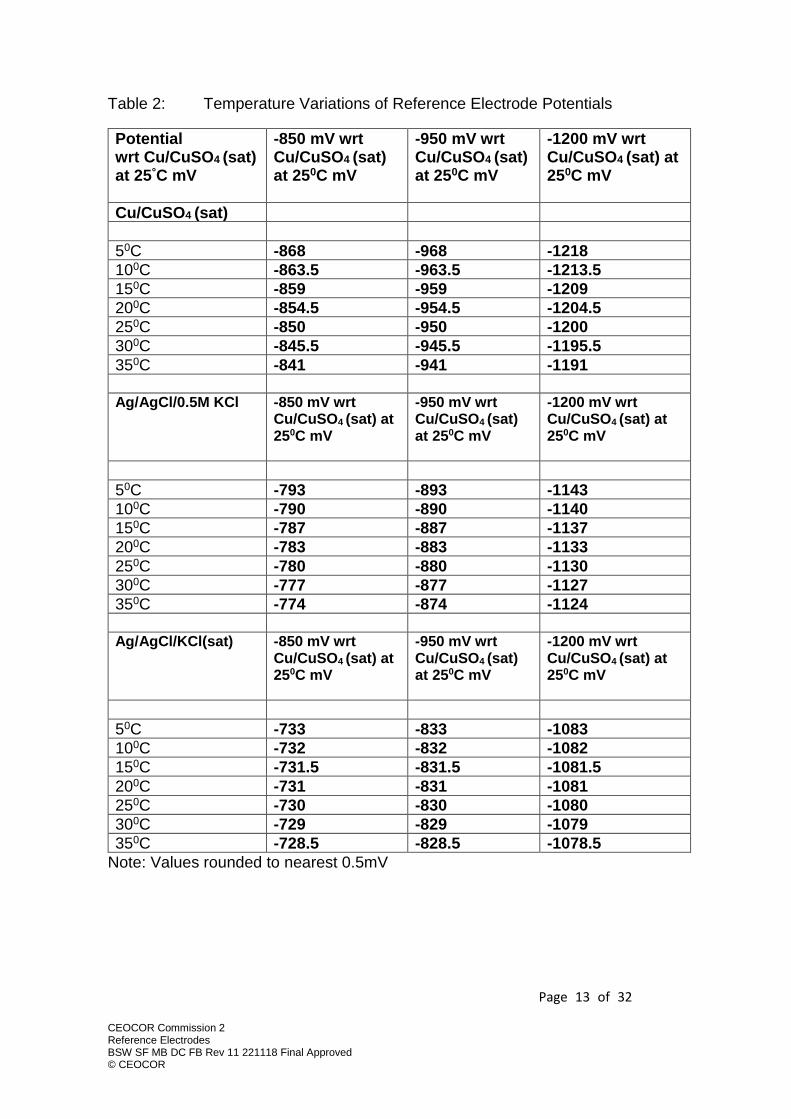
Table 2: Temperature Variations of Reference Electrode Potentials
Potential wrt Cu/CuSO4 (sat) at 25°C mV
-850 mV wrt Cu/CuSO4 (sat) at 250C mV
-950 mV wrt Cu/CuSO4 (sat) at 250C mV
-1200 mV wrt Cu/CuSO4 (sat) at 250C mV
Cu/CuSO4 (sat)
50C -868 -968 -1218
100C -863.5 -963.5 -1213.5
150C -859 -959 -1209
200C -854.5 -954.5 -1204.5
250C -850 -950 -1200
300C -845.5 -945.5 -1195.5
350C -841 -941 -1191
Ag/AgCl/0.5M KCl -850 mV wrt
Cu/CuSO4 (sat) at 250C mV
-950 mV wrt Cu/CuSO4 (sat) at 250C mV
-1200 mV wrt Cu/CuSO4 (sat) at 250C mV
50C -793 -893 -1143
100C -790 -890 -1140
150C -787 -887 -1137
200C -783 -883 -1133
250C -780 -880 -1130
300C -777 -877 -1127
350C -774 -874 -1124
Ag/AgCl/KCl(sat) -850 mV wrt
Cu/CuSO4 (sat) at 250C mV
-950 mV wrt Cu/CuSO4 (sat) at 250C mV
-1200 mV wrt Cu/CuSO4 (sat) at 250C mV
50C -733 -833 -1083
100C -732 -832 -1082
150C -731.5 -831.5 -1081.5
200C -731 -831 -1081
250C -730 -830 -1080
300C -729 -829 -1079
350C -728.5 -828.5 -1078.5
Note: Values rounded to nearest 0.5mV
Page 14 of 32
CEOCOR Commission 2 Reference Electrodes BSW SF MB DC FB Rev 11 221118 Final Approved © CEOCOR
3.5 Electrode Construction issues
The porosity of the ‘porous plug’ will significantly affect the life and accuracy of both permanent and portable reference electrodes but the effect is much more significant for permanent electrodes which, when buried, cannot be easily inspected, tested, cleaned and refilled with uncontaminated electrolytes. Not only can contaminants such as chlorides (and other halides and sulphides) enter the electrode and contaminate it but, for example for Cu/CuSO4 (sat), the copper ions will also diffuse through the porous plug until the solution is no longer saturated and the potential changes in accordance with the Nernst equation above. The porous plug pore size and path length will determine the diffusion rates of species through the plug. The concentration gradient across the porous plug will also influence the rate of diffusion. As such the diffusion rate (loss) of chlorides from a 0.5M KCl electrolyte in a Ag/AgCl/KCl electrode (see below) will be less than from a 4M KCl electrode, if all other factors are identical. However, the logarithmic relationship between potential and electrolyte concentration offsets the potential change arising from diffusion. Junction potentials also form across the porous plug due to differing diffusion rates between cations and anions. Most permanent electrodes and some of those portable electrodes which include fixed concentration electrolytes utilise gelling agents to limit the diffusion of electrolyte through the porous lug. Historically permanent Cu/CuSO4 (sat) reference electrodes have used ‘gelling agents’ of wood dust (saw dust) and ‘plaster of Paris’ (gypsum plaster, or calcined gypsum, CaSO4.0.5 H2O, which re-hydrates to CaSO4.2H20 when mixed with water) have been used. The latter has also been used in a variety of Ag/AgCl/ KCl portable and permanent electrodes. There are commercially available gelling agents such as carbopol polyacrylic acid gelling agents neutralised with NaOH, acrylic acid, carboxy polymethylene, carboxymethyl cellulose, methyl cellulose, algin, agar, polyethylene oxide, polyvinyl alcohol, and mixtures thereof, as suitable gelling agents. Of these, agar and agarose have been widely used for laboratory electrodes but suffer from drying and microbial activity.20 Hydroxyethyl cellulose and methyl cellulose are both reported to have been used commercially.20
3.6 Diffusion and Streaming Potentials: Errors
In order to measure the electrochemical potential of a pipeline steel/electrolyte interface, a reference electrode has to be positioned22 somewhere in the soil electrolyte that is in contact with the pipeline and the potential measured with a voltmeter. Other examples are the measurement of the potential of reinforcement
22 In the case of measurements of coupon or probe potentials, the reference electrode is placed near the coupon or the probe or may be integrated into the probe or coupon.

Page 15 of 32
CEOCOR Commission 2 Reference Electrodes BSW SF MB DC FB Rev 11 221118 Final Approved © CEOCOR
steel in concrete, where the reference electrode is placed on the concrete surface, or the measurement of the potential of an offshore structure, where the reference electrode is positioned in the seawater. The reference electrode should, preferably, be as close to the working electrode (the steel), as possible. However, for practical reasons, this is often not the case. Thus, in many situations, the reference electrode is some distance from the steel/electrolyte interface. Consider, for example, the reference electrode inserted in the upper 10 centimeters of soil, used to measure the pipe/soil potential buried tens of meters away. There are two effects that arise under such conditions and that may markedly impair the accuracy of the potential measurement. The first effects are “diffusion potentials”, and the second “streaming potentials”. Diffusion potentials arise whenever there are differences in chemical composition between the electrolyte directly in contact with the working electrode (steel) and the electrolyte directly in contact with the reference electrode. In other words, in cases where the soil liquid has a different chemistry at the location of the pipeline than within the uppermost soil layer (where the reference electrode is located), a diffusion potential will arise and arithmetically add to the electrochemical potential of the pipeline. The measured potential at the voltmeter is thus the sum of the “true pipeline potential” and the diffusion potential. Thus, diffusion potentials are a source of error for potential measurements. In soil, the chemistry of the pore liquid will certainly differ from one location to another, e.g. in terms of pH or concentrations of sulfate, chloride, etc. Particularly, a pH gradient will give rise to pronounced diffusion potentials. In any case, this source of error can easily exceed 10 mV or even 100 mV (strongly depending on the actual conditions) and thus contribute a significant error in the pipe/soil potential measurement. In the case of movement of a liquid through a porous system, interaction between the dissolved ionic species and the pore walls is likely to occur. This means that some species are “held back” by this electrical interaction, while other species less strongly affected. For instance, positively charged particles are decelerated, while negatively charged particles are not (or less) affected. This gives again rise to a potential difference that affects the measurement. These potential differences are usually termed “streaming potentials”. Porous materials (soil, concrete, etc.) seldom exhibit homogenous moisture distributions, and thus, streaming potentials arise. For the case of concrete, these streaming potentials may easily exceed 100 mV. As a conclusion, diffusion and streaming potentials are serious error sources for potential measurements whenever the reference electrode cannot be placed in direct vicinity of the working electrode. Their magnitude depends strongly on the actual

Page 16 of 32
CEOCOR Commission 2 Reference Electrodes BSW SF MB DC FB Rev 11 221118 Final Approved © CEOCOR
conditions, but they can establish errors of several tens of mV or even exceed 100 mV.23 Particularly significant errors are likely when attempting to measure pipe/soil potential values under concrete hard-standings or road crossings with portable reference electrodes placed on the concrete surface. 3.7 Nomenclature In all of the above, the strictly correct designation of, for example, the commonly referred to Cu/CuSO4 (sat) reference electrode is actually CuCuSO4 (sat) reference electrode. The Ag/AgCl/0.5M KCl reference electrode is more correctly AgAgCl0.5M KCl. The latter (using ) format is found in some scientific texts and very occasionally in cathodic protection engineering texts by those trying to impress. The former (using /) is in ubiquitous technical and engineering use and is used in this document.
23 Angst U, Vennesland, Ø, Myrdal, R. Diffusion potentials as source of error in electrochemical measurements in concrete, Materials and Structures 42 (2009) 365-375.

Page 17 of 32
CEOCOR Commission 2 Reference Electrodes BSW SF MB DC FB Rev 11 221118 Final Approved © CEOCOR
4.0 Permanent Reference Electrodes Reference electrodes are regularly buried for permanent monitoring close to buried pipelines. The installation can be either by direct burial of the reference electrode close to the pipe or, in some applications, the reference electrode can be installed within or directly below a chamber or box with access at ground level, typically above the pipeline. This is to facilitate calibration and replacement of the reference electrode with the avoidance of excavation, resulting in reduced costs. These permanent reference electrodes may be included with or integrated into coupons which facilitate measurement of IR error free pipe/soil potentials. Permanent reference electrodes are frequently used in conjunction with permanent monitoring systems which enable pipe/soil potential data to be recorded and transmitted to the pipeline operator or specialist surveillance contractors. In areas of dc fluctuating stray current, such as rail or tram traction currents they may be used in conjunction with automatic potentiostatic (potential controlled) transformer rectifiers (dc power supplies) to maintain relatively stable pipe/soil potentials under fluctuating stray current conditions. In these applications reference electrodes can be subjected to different operating parameters. They may be:
a. Normally open circuit; only used for intermittent measurement when personnel visit the installation with portable instrumentation to measure pipe/soil potentials. These measurements may be of ON potentials (including unquantified IR errors) or may be Instant OFF measurements with reduced or no IR errors (either by switching OFF all the CP and interaction current related to the pipeline or using coupons).
b. Regularly interrogated by a monitoring system that measures pipe/soil/reference electrode potential perhaps daily or many times per day (often to immediately or later transmit the data) but open circuit between these measurements.
c. Regularly interrogated by a monitoring system that measures pipe/soil/reference electrode potential perhaps daily or many times per day (often to immediately or later transmit the data) but remaining closed circuit, and effectively measuring, between these measurements.
d. Permanently connected into a closed loop potential control circuit which results in a constant function of the reference electrode and determines the operating parameters of a dc power source or transformer rectifier. In this application there is a continuous current drain through the reference electrode, the magnitude is determined by the input impedance of the DC power source measurement circuit. High input impedance is necessary to mitigate polarisation of the electrode.
These four options result in different operational characteristics for the reference electrode and may be important in determining the appropriate input impedance of the measurement device and its influence on both the accuracy and life of the

Page 18 of 32
CEOCOR Commission 2 Reference Electrodes BSW SF MB DC FB Rev 11 221118 Final Approved © CEOCOR
reference electrode. Permanently buried electrodes generally cannot be cleaned, recharged with electrolyte or otherwise maintained, unless installed within or immediately below a chamber or box with access at ground level. If they are very inaccurate, or damaged, they should be replaced; methods for assessing their accuracy are necessary. 4.1 Accuracy and Environmental Issues The electrode potential of reference electrodes is dependent on the concentration of and species within the electrolyte. Changes in concentration of copper sulphate with permanent Cu/CuSO4 (sat) reference electrodes or contamination by chlorides (or other halides or sulphides) will affect accuracy. Similarly changes in chloride concentration or contamination for Ag/AgCl/0.5M KCl or other molarity reference electrodes will seriously affect accuracy. The accuracy of reference electrodes for permanent applications is dependent upon maintaining the fixed concentration of electrolyte (CuSO4 saturated in Cu/CuSO4 (sat) reference electrodes and various concentrations of KCl in Silver/Silver Chloride/Potassium Chloride electrodes). Accuracy is also dependent on these electrolytes not being contaminated with species that would change the electrode potential (e.g. halides affecting Cu/CuSO4 (sat) reference electrodes). It is obvious that the longevity and accuracy of permanently installed reference electrodes is strongly dependent on the diffusion characteristics of the porous pots or porous plugs of the electrode housing and on any influence on mobility of the dissolved salts in the electrolyte of any gelling agents. These factors are seldom disclosed by manufacturers and there is little published data on commercially available reference electrodes. These factors are likely to be of particular importance in environments with freely draining soils such as sands and gravels where the water table is above the electrode burial depth; if the diffusion rate of the electrolyte from within the electrode body is too high, and the volume within the body too low, significant errors will be established quickly. It is normally required that the current drain though reference electrodes is minimised by the use of high impedance measurement circuits, either in the portable digital voltmeters or in the fixed monitoring and/or control applications within either fixed/remote monitoring applications or in the use of potentiostatically controlled transformer rectifiers/power supplies. A field study presented in CEOCOR 20137 presented field data for a range of proprietary ‘high quality’ reference electrodes from reputable manufactures in Europe and North America; many were significantly inaccurate after only a few months of burial subjected to operating parameter a. above. One electrode type exhibited errors of over 300mV, others had errors of around 200mV. ‘Old style’ large porous pot electrodes performed relatively well in the test period; only 3 of 11

Page 19 of 32
CEOCOR Commission 2 Reference Electrodes BSW SF MB DC FB Rev 11 221118 Final Approved © CEOCOR
Cu/CuSO4 (sat) reference electrodes tested were stable to within 20mV during the test period of 32 weeks. One type of Ag/AgCl/0.5M KCl reference electrode was one of the most stable electrodes tested and was selected for permanent installation.
Page 20 of 32
CEOCOR Commission 2 Reference Electrodes BSW SF MB DC FB Rev 11 221118 Final Approved © CEOCOR
5.0 Portable Reference Electrodes Portable reference electrodes are used by personnel for intermittent measurements at test facilities and also in close interval potential surveys (CIPS) and DC voltage gradient surveys (DCVG). They are generally utilised in conjunction with high input impedance digital voltmeters (although some DCVG survey equipment utilises relatively low input impedance analogue instruments). Generally, the accuracy and life of portable reference electrodes is not adversely affected by characteristics of the measurement devices (unless inappropriately low in quality and price plus low input impedance digital or analogue voltmeters are used). The life of portable reference electrodes is generally determined by mechanical damage, wear and tear and maintenance. Some electrodes (notably the copper/copper sulphate (saturated) reference electrode) can be regularly cleaned and recharged with electrolyte. All portable reference electrodes can be and should be regularly check calibrated according to their use. All test leads shall be clean, fully insulated, fitted with appropriate plugs and connection clips for the measurement device and test facility and should be undamaged. Significant errors can be introduced if corrosion products, moisture and ‘dirt’ are in place at the various connections. The same issues are applicable, at least in part to permanently installed electrodes. It is essential that all cable connections to electrode elements are insulated/encapsulated in a suitable manner for long term burial/immersion and that all connections and terminations are protected from contamination and moisture. The use of multiple input impedance voltmeters (100MΩ and 1000MΩ units are manufactured specifically for CP, historically some general-purpose digital voltmeters have been switchable between 10MΩ and 1000MΩ) can be useful in detecting if electrode to soil resistance is introducing errors into the potential measurements. Historically Wheatstone Bridge based instruments with low impedance moving coil meters were used which allowed the measurement current to be zeroed and there to be no significant error due to electrode/soil contact. The Australian Standard for CP of Pipes and Cables 3 includes specific requirements with respect to circuit resistance and the impact of high soil resistivity on electrode to soil resistance.

Page 21 of 32
CEOCOR Commission 2 Reference Electrodes BSW SF MB DC FB Rev 11 221118 Final Approved © CEOCOR
6.0 Reference Electrode Parameters: Permanently Installed Electrodes
As detailed above, the selection of reliable and accurate permanent reference electrodes is not well documented. The following recommendations are proposed in order to enhance and define the quality of reference electrodes and to optimise their use in the field.
I. Permanently buried reference electrodes are subject to errors and shall not be used as the sole source of data for cathodic protection performance evaluation without routine checking and evaluation of measurement accuracy.
II. Permanent reference electrodes may be used as sensing electrodes for permanent remote monitoring of buried pipeline cathodic protection or for the control of potential controlled DC power supplies, but the pipeline/structure operator and CP assessment specialists shall take into account that reference electrode errors may be significant and vary in magnitude with time.
III. Permanent reference electrode accuracy should be assessed using calibrated portable reference electrodes taking into account the purpose of the data. As a minimum, this should be conducted during every detailed and comprehensive assessment of Cathodic Protection performance. This is particularly important where the pipeline potential levels are maintained by values recorded against reference electrodes i.e. in potentiostatic (also known as auto-potential) mode because the control potentials can fluctuate significantly due to erroneous and changing reference electrode potential values. The practice of operating potential-controlled systems on the basis that the reference electrode typically has errors of +/-200mV from a calibrated electrode should be discouraged. Testing facilities and intervals between testing shall be sufficient to ensure that any reliance on the accuracy of permanent reference electrodes is supported by adequate measurements with calibrated portable reference electrodes at time intervals based upon known performance of the permanent reference electrodes used.
It is recommended that all permanent reference electrodes used for assessment of Cathodic Protection performance shall have provision for the proximate (close) location of calibrated portable reference electrodes so that the electrode potential of the permanent unit can be checked with respect to the calibrated portable unit at time intervals determined as necessary to ensure adequate performance of the CP system. Such a provision may be the installation of the reference electrode within, or immediately below, an easily accessible chamber or box, the installation of a plastic pipe that can be filled with water or the installation of a plastic tube that allows for lowering a mobile reference electrode to the level of the permanent one.

Page 22 of 32
CEOCOR Commission 2 Reference Electrodes BSW SF MB DC FB Rev 11 221118 Final Approved © CEOCOR
This is particularly important, but difficult to install after construction, at locations where the pipeline is covered by concrete or tarmac. Even in green field locations, if the electrode is buried at pipe level, such provisions are valuable. The following are optimum target performance parameters for permanent reference electrodes; it is recommended that these are used in purchase specifications for the reference electrodes. It is noted that most reference electrode producers do not disclose the full details of their products or warrant accuracy or life. This may be addressed by undertaking the following:
a. Undertake medium term trials (minimum 6 months) in the intended environment
b. Analysing build quality and check components with respect to composition and purity
c. Publishing the collecting the results and build a database within CEOCOR This would allow for a mutual increase in understanding of the very basic performance aspects of reference electrodes. Target Parameters and Basis of Proposed Purchase Specification are given in Annex B. Other methods of approximately check calibrating permanently buried reference electrodes without access tubes or Luggin probes have been proposed and trialled, notably by Spanish experts from Gas Natural Fenosa and Guldager Electrólisis. These techniques have been presented within the CEOCOR Work Groups but not yet formally published. They show promise and involve the recording of field gradients in fluctuating interaction conditions and the concurrent measurement of permanent electrode to a portable electrode placed above it. If the field gradient is, at times, zero then the voltage gradient between the permanent and portable electrodes should also be zero. Thus, the measured potential difference at effectively zero voltage gradient can be used as a check calibration value.24
24 Verification of Permanent Reference Electrodes. Orta A, Gomila A. CEOCOR Work Group presentation Weimar 2014. Accessible from Lluis Gomila <[email protected]>

Page 23 of 32
CEOCOR Commission 2 Reference Electrodes BSW SF MB DC FB Rev 11 221118 Final Approved © CEOCOR
7.0 Reference Electrode Parameters: Portable Electrodes
Portable reference electrodes used for buried pipeline applications are almost exclusively examples of the Cu/CuSO4 (sat) reference electrode. Even in high chloride environments such as pipeline landfalls, crossings of estuaries, saline swamps etc. where contamination of the electrode electrolyte with chlorides is a real threat to accuracy, with appropriate frequent visual inspection of the electrolyte and copper electrode, regularly calibration checks, cleaning the porous plug and, as necessary changing the electrolyte and cleaning, this reference electrode can maintain accuracy. For such locations portable Ag/AgCl/0.5M KCl reference electrodes are also available.9. They are widely used for surveying steel/concrete potentials in reinforced concrete highway structures, marine civil structures and similar and can be used on and in soils. It should be obvious that Ag/AgCl/sea water portable electrodes which rely on the sea water as the electrolyte cannot be used in soil applications. Portable reference electrodes are generally purchased as proprietary items and not against performance specifications or with extensive data sheets. The optimum target performance parameters for portable reference electrodes that should be used in purchase specifications for these units are given in Annex B.
Page 24 of 32
CEOCOR Commission 2 Reference Electrodes BSW SF MB DC FB Rev 11 221118 Final Approved © CEOCOR
8.0 Installation Procedures for Permanent Reference Electrodes The ideal position for installing the permanent reference electrode depends on a number of factors: The measurement value of interest influences the correct position of the reference electrode. The parameter to be assessed e.g. on-potential, the local field gradients, an approach to an IR-free potential, impact on the optimum reference electrode location. Correspondingly the optimum position of the reference electrode may be at remote earth, or at some "relevant position" or within 100-500 mm from the pipeline at invert level. The presence, location and magnitude of field gradients generated by the pipeline, the anode bed or third-party infrastructure may influence the selected reference electrode location. The field gradients may have a time dependence and no single location may be optimum for all conditions. The environment may change; both ground water and sea water level change with time and it may be necessary to measure pipe/soil potentials at different elevations around the pipeline. When permanent Cu/CuSO4 (sat) reference electrodes are buried at pipeline depth, in soil, the distance to the pipeline must be sufficient to prevent electro-deposition of copper onto the pipeline. Similarly, if permanent reference electrodes are used with coupons they should, if Cu/CuSO4 (sat), be spaced to prevent this effect, or alternative reference electrodes should be used. For installation post construction, ‘no dig’ or ‘minimum dig’ techniques can be used for installation including hand and machine screw auger, water jetting auger and vacuum auger techniques, to prepare a hole, sometimes lined, to electrode depth. These techniques may dictate the use of reference electrodes of limited diameter. Care should be taken when positioning electrodes so that they are not ‘choked’ inside tubes by debris or animals. If geotextiles are used to prevent sand of similar ingress into tubes it shall be selected and tested to not be hydrophobic or to form an electrolytically resistive barrier between the electrode and the soil. Alternatively, the installation of reference electrodes within, or immediately below, surface chambers or boxes can be used in order to allow for easy check calibration and replacement. When doing so, the above requirements must also be considered. It is recommended that all permanent reference electrodes should be provided with methods of field function check and re-calibration when installed. One method is to provide a plastic tube from ground level to immediately adjacent to the electrode allowing the introduction of a portable calibrated reference electrode close to the permanent reference electrode for calibration when the site is visited by CP personnel. It is theoretically possible to introduce a form of Luggin capillary probe between the above ground test facility and the reference electrode; this may be
Page 25 of 32
CEOCOR Commission 2 Reference Electrodes BSW SF MB DC FB Rev 11 221118 Final Approved © CEOCOR
more satisfactory in some applications to the provision of a plastic tube between the ground level and the electrode. This is particularly important, but difficult to install after construction, at locations where the pipeline is covered by concrete or tarmac. Even in green field locations, if the electrode is buried at pipe level, such provisions are valuable. These provisions for checking depend primarily on the presence of IR-errors and are especially important in the case of field gradients generated by third parties.

Page 26 of 32
CEOCOR Commission 2 Reference Electrodes BSW SF MB DC FB Rev 11 221118 Final Approved © CEOCOR
9.0 Pre-Commissioning and Commissioning Procedures All permanent reference electrodes should be subject to the calibration and validation stages detailed in Annex B.
Page 27 of 32
CEOCOR Commission 2 Reference Electrodes BSW SF MB DC FB Rev 11 221118 Final Approved © CEOCOR
ANNEX A
Possible Scheme for Control/Calibration of Reference Electrodes
A-1 Suggested Glossary
i.Primary Standard Reference Electrode (PSRE): standard reference electrode, used only in the laboratory. This may be a standard hydrogen electrode.
ii.Secondary Standard Reference Electrode (SSRE): reference electrode used in laboratory. This electrode is used on the arrangement detailed in A-2 below for the measurement (or ‘control’) of the electrode potentials of other reference electrodes, in particular the ‘Master Working Reference Electrode’ below. This electrode is itself periodically calibrated against a PSRE by an external accredited laboratory.
iii.Master Working Reference Electrode (MWRE): reference electrode used on site, for site calibration of reference electrodes. The MWRE is calibrated against the SSRE.
iv.Measurement Reference Electrode (MRE): Reference electrode which is used on site or in laboratory in order to carry out potential measurements. The MRE is controlled against the MWRE. During field surveys it is common practice to check different MREs against each other.
v.Maximum Agreed Error (MAE): corresponds to the maximum accepted deviation between the potential of the electrode to be calibrated and the SSRE. The MAE can be determined by the maximum achievable precision of the reference electrode but it can also be much less restrictive than the theoretical minimum value and be determined pragmatically depending on the accuracy/precision of the measurement requirements. The above scheme is one developed and reportedly in use by a large operating pipeline company with many field CP operatives using many reference electrodes. For those companies with fewer reference electrodes deployed it would be possible to delete one layer of complexity as is detailed below in A-2

Page 28 of 32
CEOCOR Commission 2 Reference Electrodes BSW SF MB DC FB Rev 11 221118 Final Approved © CEOCOR
A-2 Scheme for laboratory calibration/control of Reference Electrodes
Key: 1 : ‘Secondary Standard Reference Electrode (SSRE)’ (saturated calomel electrode or Ag/AgCl/0.5M KCl electrode), 1. This electrode is only used in the laboratory and is itself traceable back to a Primary Standard Reference Electrode 2 : ‘Master Working Reference Electrode (MWRE)’ which is being calibrated/subject to control, in this test in the laboratory. This electrode is then used on site to calibrate/control ‘Measurement Reference Electrodes’ which are used for site potential measurements 3 : Voltmeter (DC. mV scale), high impedance (≥ 10 MΩ), sensitivity ≥ 0.01mV, accuracy of, or better than, +/- 0.1%. This voltmeter should be calibrated in a traceable manner back to a National Standard and should be check calibrated at the start of this process to a portable or laboratory calibrator, itself calibrated in a traceable manner back to a National Standard. The calibrator should have an accuracy of, or better than, +/- 0.05% +/- 2 counts 4 : Saturated Potassium Chloride (KCl) solution if saturated calomel electrode is being used as the ‘Secondary Standard Electrode’. IF using Ag/AgCl/0.5M KCl as the ‘Secondary Standard Electrode’, this should be 0.5M KCL 5 : Solution; KCl (saturated for calomel, 0.5MKCl for Ag/AgCl/0.5M KCl) or saturated CuSO4 if Cu/CuSO4 (sat) electrode) 6 : Sponge 7 : Cap/stopper 8 : Electrolytical bridge (porous material)
Page 29 of 32
CEOCOR Commission 2 Reference Electrodes BSW SF MB DC FB Rev 11 221118 Final Approved © CEOCOR
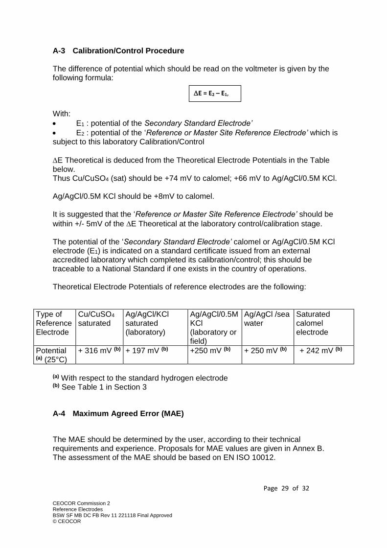
A-3 Calibration/Control Procedure The difference of potential which should be read on the voltmeter is given by the following formula: With:
• E1 : potential of the Secondary Standard Electrode’
• E2 : potential of the ‘Reference or Master Site Reference Electrode’ which is subject to this laboratory Calibration/Control
E Theoretical is deduced from the Theoretical Electrode Potentials in the Table below. Thus Cu/CuSO4 (sat) should be +74 mV to calomel; +66 mV to Ag/AgCl/0.5M KCl. Ag/AgCl/0.5M KCl should be +8mV to calomel. It is suggested that the ‘Reference or Master Site Reference Electrode’ should be
within +/- 5mV of the E Theoretical at the laboratory control/calibration stage. The potential of the ‘Secondary Standard Electrode’ calomel or Ag/AgCl/0.5M KCl electrode (E1) is indicated on a standard certificate issued from an external accredited laboratory which completed its calibration/control; this should be traceable to a National Standard if one exists in the country of operations. Theoretical Electrode Potentials of reference electrodes are the following:
Type of Reference Electrode
Cu/CuSO4 saturated
Ag/AgCl/KCl saturated (laboratory)
Ag/AgCl/0.5M KCl (laboratory or field)
Ag/AgCl /sea water
Saturated calomel electrode
Potential (a) (25°C)
+ 316 mV (b) + 197 mV (b) +250 mV (b) + 250 mV (b) + 242 mV (b)
(a) With respect to the standard hydrogen electrode (b) See Table 1 in Section 3
A-4 Maximum Agreed Error (MAE)
The MAE should be determined by the user, according to their technical requirements and experience. Proposals for MAE values are given in Annex B. The assessment of the MAE should be based on EN ISO 10012.
E = E2 – E1,

Page 30 of 32
CEOCOR Commission 2 Reference Electrodes BSW SF MB DC FB Rev 11 221118 Final Approved © CEOCOR
ANNEX B
Target values for Maximum Agreed Errors (MAEs) and Parameters as Basis of Purchase Specification Introduction Annex B provides target values for Maximum Agreed Errors (MAE). This terminology is based on the one used in Annex A. B-1 Permanent (Measurement) reference electrodes
i. The permanent measurement reference electrode (MRE) shall be calibrated with respect to a Secondary Standard Reference Electrode (SSRE) according to Annex A by the manufacturer before despatch. The reference electrodes shall be within a Maximum Agreed Error of their advertised potential, as defined by the purchaser according to the needs and practices of the intended user. Typical values are +/- 5 to +/-10mV of their advertised potential. Each electrode shall have a unique serial number. The calibration record shall be made available to the purchaser. It is noted that some types of Cu/CuSO4 (sat) reference electrodes are shipped by the manufacturer ‘dry’ and these need to be soaked before their electrode potential can be measured. It is suggested that item (i),. above is replaced in such cases with typical data for electrodes of identical design, materials and assembly testing intermittently by the manufacturer.
ii. Reference electrodes may be validated with respect to a Master Working Reference Electrode (MWRE) by the purchaser or installer immediately before installation and typically are within a corresponding 10 to 20mV range of their advertised potential or some larger Maximum Agreed Error defined by the user according to its needs and practices. These pre-installation validations shall either be at 20°C (to avoid temperature variations between
different types of electrode) or shall utilise electrodes of an identical type, and thus the same temperature coefficient. The calibration record, identifying the unique serial number shall be maintained as a record related to the installation. Details of the intended installation and conditions shall also be recorded.
iii. Reference electrodes shall be validated (or controlled) with respect to a
Master Working Reference Electrode (MWRE) by the purchaser or installer immediately after installation (including cable termination) and should be within the appropriate range 0 to 10/20mV (depending on above) of their advertised potential, or some larger Maximum Agreed Error defined by the user according to its needs and practices. The validation record,
Page 31 of 32
CEOCOR Commission 2 Reference Electrodes BSW SF MB DC FB Rev 11 221118 Final Approved © CEOCOR
identifying the unique serial number shall be maintained as a record related to the installation.
iv. The reference electrode design and quality should be such that during the service life of the reference electrode its potential should be expected to remain within +/- 30mV of their declared electrode potential, or some larger Maximum Agreed Error defined by the user according to its needs and practices. This shall be measured with respect to Master Working Reference Electrode (MWRE) temporarily placed close to the permanent electrodes, at intervals determined by the pipeline/structure operator and CP assessment specialists advising them, as appropriate to demonstrate adequate functionality and accuracy for the purpose for which the permanent reference electrode is utilised in accordance with EN ISO 15589-1. It is noted that many reference electrodes fail to meet this +/-30mV requirement during service.
v. The minimum design service life of permanent reference electrodes should
be 10 years. The optimum service life of permanent reference electrodes shall be 25 years. These requirements are proposed to be used in purchase specifications, but it should be acknowledged within the pipeline/structure operator team and by CP assessment specialists that this service life and the target accuracy may not be met. Further, claims by manufacturers of accuracy or extended service lives may not be demonstrated or delivered in practice. Appropriate measures shall be in place to determine failure or loss of required accuracy of reference electrodes and to ensure that these likely occurrences do not adversely affect pipeline cathodic protection levels or their assessment.
B-2 Portable (Measurement) reference electrodes
i. If the portable MRE is supplied complete i.e. ‘wet’ and filled with the electrolyte, they shall be calibrated with respect to a Secondary Standard Reference Electrode (SSRE) according to Annex A by the manufacturer before despatch. The reference electrodes shall be within a Maximum Agreed Error of their advertised potential, as defined by the purchaser according to the needs and practices of the intended user. Typical values are +/- 5mV of their advertised potential. Each electrode shall have a unique serial number. The calibration record shall be made available to the purchaser.
ii. Some portable copper/copper sulphate electrodes are supplied dry, sometimes with a small deposit of Cu/CuSO4 crystals dispensed in the tube, and it may not be possible for the manufacturer to calibrate every cell. In such cases, the manufacture shall establish a formal Quality Management
Page 32 of 32
CEOCOR Commission 2 Reference Electrodes BSW SF MB DC FB Rev 11 221118 Final Approved © CEOCOR
programme and inspection and testing regime to prove that the electrodes have this accuracy.
iii. Portable measurement reference electrodes shall be calibrated with respect to a Secondary Standard Reference Electrode (SSRE), according to Annex A, by the user immediately before first use and shall be within ± 10mV of their advertised potential or some larger Maximum Agreed Error defined by the user according to its needs and practices. The calibration record, identifying the unique serial number, shall be maintained as a record related to the electrode.
iv. Portable MREs shall be maintained clean externally, with their cables and any terminals/leads in good condition. Cu/CuSO4 (sat) reference electrodes shall be regularly visually inspected for their electrolyte level, colour (clear bright blue), the presence of excess suspension of hydrous CuSO4.5H2O in de-ionised water, and the electrode condition which should be clean, bright copper surface with no black or green deposits).
v. Portable measurement reference electrodes shall be inspected and controlled / calibrated in the field with respect to a Master Working Reference Electrode (MWRE) based on a regular schedule. This schedule shall take into account the significance and relevance of the measurements in which the portable measurement reference electrodes are used. It may be appropriate to control / calibrate the portable measurement reference electrodes on a daily basis, or weekly, or at the start and end of each critical campaign of data collection in order to ensure that the Maximum Agreed Error is not exceeded.
vi. Depending on the type of measurements for which the measurement reference electrodes are deployed, additional checks among different measurement reference electrodes may be required during the daily measurement routine. This may be especially relevant in case of measurement techniques that intend to measure small and absolute voltage gradients, such as the intensive measurement technique.25
vii. The life of the portable reference electrode will likely be determined by mechanical damage; wear to the porous plug or failure of seals especially rubber seals. Some manufacturers offer replaceable porous plugs and seals. A reasonable life expectancy is 5 years. In reality, most portable electrodes are lost, and so having at least two spares is essential.
viii. Some manufacturers offer refurbishment of sealed portable reference electrodes such as Ag/AgCl/0.5M KCl reference electrodes.
25 EN ISO 15589-1 Cathodic Protection of Pipeline Systems – Part 1: On Land Pipelines Annex D.3.2