reference architectures 2017 deploying mobile … · reference architectures 2017 deploying mobile...
TRANSCRIPT
Ajay Simha
Reference Architectures2017Deploying mobile networks usingnetwork functions virtualization

Reference Architectures 2017 Deploying mobile networks using networkfunctions virtualization
Ajay [email protected]

Legal Notice
Copyright © 2017 Red Hat, Inc.
The text of and illustrations in this document are licensed by Red Hat under a Creative CommonsAttribution–Share Alike 3.0 Unported license ("CC-BY-SA"). An explanation of CC-BY-SA isavailable athttp://creativecommons.org/licenses/by-sa/3.0/. In accordance with CC-BY-SA, if you distribute this document or an adaptation of it, you mustprovide the URL for the original version.
Red Hat, as the licensor of this document, waives the right to enforce, and agrees not to assert,Section 4d of CC-BY-SA to the fullest extent permitted by applicable law.
Red Hat, Red Hat Enterprise Linux, the Shadowman logo, JBoss, OpenShift, Fedora, the Infinitylogo, and RHCE are trademarks of Red Hat, Inc., registered in the United States and othercountries.
Linux ® is the registered trademark of Linus Torvalds in the United States and other countries.
Java ® is a registered trademark of Oracle and/or its affiliates.
XFS ® is a trademark of Silicon Graphics International Corp. or its subsidiaries in the United Statesand/or other countries.
MySQL ® is a registered trademark of MySQL AB in the United States, the European Union andother countries.
Node.js ® is an official trademark of Joyent. Red Hat Software Collections is not formally related toor endorsed by the official Joyent Node.js open source or commercial project.
The OpenStack ® Word Mark and OpenStack logo are either registered trademarks/service marksor trademarks/service marks of the OpenStack Foundation, in the United States and other countriesand are used with the OpenStack Foundation's permission. We are not affiliated with, endorsed orsponsored by the OpenStack Foundation, or the OpenStack community.
All other trademarks are the property of their respective owners.
AbstractThe purpose of this document is to serve as a reference architecture for deploying mobile networksusing network functions virtualization

. . . . . . . . . . . . . . . . . . . . . . . . . . . . . . . . . . . . . . . . . . . . . . . . . . . . . . . . . . . . . . . . . . . . . . . . . . . . . . . . . . . . . . . . . . . . . . . . . . . . . . . . . . . . . . . . . . . . . . . . . . . . . . . . . . . . . . . . . . . . . . . . . . . . . . . . . . . . . . . . . . . . . . . . . . . . . . . . . . . . . . . . . . . . . . . . . . . . . . . . . . . . . . . . . . . . . . . . . . . . . . . . . . . . . . . . . . . . . . . . . . . . . . . . . . . . . . . . . . . . . . . . . . . . . . . . . . . . . . . .
. . . . . . . . . . . . . . . . . . . . . . . . . . . . . . . . . . . . . . . . . . . . . . . . . . . . . . . . . . . . . . . . . . . . . . . . . . . . . . . . . . . . . . . . . . . . . . . . . . . . . . . . . . . . . . . . . . . . . . . . . . . . . . . . . . . . . . . . . . . . . . . . . . . . . . . . . . . . . . . . . . . . . . . . . . . . . . . . . . . . . . . . . . . . . . . . . . . . . . . . . . . . . . . . . . . . . . . . . . . . . . . . . . . . . . . . . . . . . . . . . . . . . . . . . . . . . . . . . . . . . . . . . . . . . . . . . . . . . . . .
. . . . . . . . . . . . . . . . . . . . . . . . . . . . . . . . . . . . . . . . . . . . . . . . . . . . . . . . . . . . . . . . . . . . . . . . . . . . . . . . . . . . . . . . . . . . . . . . . . . . . . . . . . . . . . . . . . . . . . . . . . . . . . . . . . . . . . . . . . . . . . . . . . . . . . . . . . . . . . . . . . . . . . . . . . . . . . . . . . . . . . . . . . . . . . . . . . . . . . . . . . . . . . . . . . . . . . . . . . . . . . . . . . . . . . . . . . . . . . . . . . . . . . . . . . . . . . . . . . . . . . . . . . . . . . . . . . . . . . . .
. . . . . . . . . . . . . . . . . . . . . . . . . . . . . . . . . . . . . . . . . . . . . . . . . . . . . . . . . . . . . . . . . . . . . . . . . . . . . . . . . . . . . . . . . . . . . . . . . . . . . . . . . . . . . . . . . . . . . . . . . . . . . . . . . . . . . . . . . . . . . . . . . . . . . . . . . . . . . . . . . . . . . . . . . . . . . . . . . . . . . . . . . . . . . . . . . . . . . . . . . . . . . . . . . . . . . . . . . . . . . . . . . . . . . . . . . . . . . . . . . . . . . . . . . . . . . . . . . . . . . . . . . . . . . . . . . . . . . . . .
. . . . . . . . . . . . . . . . . . . . . . . . . . . . . . . . . . . . . . . . . . . . . . . . . . . . . . . . . . . . . . . . . . . . . . . . . . . . . . . . . . . . . . . . . . . . . . . . . . . . . . . . . . . . . . . . . . . . . . . . . . . . . . . . . . . . . . . . . . . . . . . . . . . . . . . . . . . . . . . . . . . . . . . . . . . . . . . . . . . . . . . . . . . . . . . . . . . . . . . . . . . . . . . . . . . . . . . . . . . . . . . . . . . . . . . . . . . . . . . . . . . . . . . . . . . . . . . . . . . . . . . . . . . . . . . . . . . . . . . .
. . . . . . . . . . . . . . . . . . . . . . . . . . . . . . . . . . . . . . . . . . . . . . . . . . . . . . . . . . . . . . . . . . . . . . . . . . . . . . . . . . . . . . . . . . . . . . . . . . . . . . . . . . . . . . . . . . . . . . . . . . . . . . . . . . . . . . . . . . . . . . . . . . . . . . . . . . . . . . . . . . . . . . . . . . . . . . . . . . . . . . . . . . . . . . . . . . . . . . . . . . . . . . . . . . . . . . . . . . . . . . . . . . . . . . . . . . . . . . . . . . . . . . . . . . . . . . . . . . . . . . . . . . . . . . . . . . . . . . . .
. . . . . . . . . . . . . . . . . . . . . . . . . . . . . . . . . . . . . . . . . . . . . . . . . . . . . . . . . . . . . . . . . . . . . . . . . . . . . . . . . . . . . . . . . . . . . . . . . . . . . . . . . . . . . . . . . . . . . . . . . . . . . . . . . . . . . . . . . . . . . . . . . . . . . . . . . . . . . . . . . . . . . . . . . . . . . . . . . . . . . . . . . . . . . . . . . . . . . . . . . . . . . . . . . . . . . . . . . . . . . . . . . . . . . . . . . . . . . . . . . . . . . . . . . . . . . . . . . . . . . . . . . . . . . . . . . . . . . . . .
. . . . . . . . . . . . . . . . . . . . . . . . . . . . . . . . . . . . . . . . . . . . . . . . . . . . . . . . . . . . . . . . . . . . . . . . . . . . . . . . . . . . . . . . . . . . . . . . . . . . . . . . . . . . . . . . . . . . . . . . . . . . . . . . . . . . . . . . . . . . . . . . . . . . . . . . . . . . . . . . . . . . . . . . . . . . . . . . . . . . . . . . . . . . . . . . . . . . . . . . . . . . . . . . . . . . . . . . . . . . . . . . . . . . . . . . . . . . . . . . . . . . . . . . . . . . . . . . . . . . . . . . . . . . . . . . . . . . . . . .
. . . . . . . . . . . . . . . . . . . . . . . . . . . . . . . . . . . . . . . . . . . . . . . . . . . . . . . . . . . . . . . . . . . . . . . . . . . . . . . . . . . . . . . . . . . . . . . . . . . . . . . . . . . . . . . . . . . . . . . . . . . . . . . . . . . . . . . . . . . . . . . . . . . . . . . . . . . . . . . . . . . . . . . . . . . . . . . . . . . . . . . . . . . . . . . . . . . . . . . . . . . . . . . . . . . . . . . . . . . . . . . . . . . . . . . . . . . . . . . . . . . . . . . . . . . . . . . . . . . . . . . . . . . . . . . . . . . . . . . .
Table of Contents
COMMENTS AND FEEDBACK
CHAPTER 1. EXECUTIVE SUMMARY
CHAPTER 2. BACKGROUND2.1. VIRTUAL PACKET CORE2.2. GILAN2.3. VOLTE
CHAPTER 3. ETSI3.1. NFVI
3.1.1. Compute3.1.2. Storage3.1.3. Network
CHAPTER 4. MOBILE ARCHITECTURES4.1. VEPC DEPLOYMENT MODELS4.2. GILAN4.3. VOICE OVER LTE (VOLTE)/IP MULTIMEDIA SERVICES (IMS)
CHAPTER 5. HIGH AVAILABILITY5.1. GEO-REDUNDANCY5.2. CHASSIS/BLADE REDUNDANCY5.3. DATACENTER TOPOLOGY (UNDERLAY)5.4. NFVI (OPENSTACK) AVAILABILITY5.5. APPLICATION LAYER HA
5.5.1. Host Aggregates and Availability Zones5.5.2. Shared File System5.5.3. Instance HA
CHAPTER 6. NETWORKING6.1. NEUTRON PLUG-INS6.2. IPV6 NETWORKING
CHAPTER 7. STORAGE
CHAPTER 8. PERFORMANCE AND OPTIMIZATION8.1. OPEN VSWITCH8.2. PCI PASSTHROUGH8.3. SR-IOV (SINGLE ROOT I/O VIRTUALIZATION)8.4. VHOST-USER8.5. DATA PLANE DEVELOPMENT KIT (DPDK)
8.5.1. Memory Manager8.5.2. Buffer Manager8.5.3. Queue Manager8.5.4. Flow Classification8.5.5. Poll Mode Drivers
8.6. DPDK-ACCELERATED OPEN VSWITCH (OVS-DPDK)8.7. DPDK WITH RED HAT OPENSTACK PLATFORM8.8. NUMA TOPOLOGY
8.8.1. CPU Socket Affinity8.9. HUGE PAGES8.10. CPU CONSUMPTION8.11. CPU PINNING
4
5
6788
911111212
13131516
181818202425252525
262828
29
313132333434353535363636374242434445
Table of Contents
1
. . . . . . . . . . . . . . . . . . . . . . . . . . . . . . . . . . . . . . . . . . . . . . . . . . . . . . . . . . . . . . . . . . . . . . . . . . . . . . . . . . . . . . . . . . . . . . . . . . . . . . . . . . . . . . . . . . . . . . . . . . . . . . . . . . . . . . . . . . . . . . . . . . . . . . . . . . . . . . . . . . . . . . . . . . . . . . . . . . . . . . . . . . . . . . . . . . . . . . . . . . . . . . . . . . . . . . . . . . . . . . . . . . . . . . . . . . . . . . . . . . . . . . . . . . . . . . . . . . . . . . . . . . . . . . . . . . . . . . . .
. . . . . . . . . . . . . . . . . . . . . . . . . . . . . . . . . . . . . . . . . . . . . . . . . . . . . . . . . . . . . . . . . . . . . . . . . . . . . . . . . . . . . . . . . . . . . . . . . . . . . . . . . . . . . . . . . . . . . . . . . . . . . . . . . . . . . . . . . . . . . . . . . . . . . . . . . . . . . . . . . . . . . . . . . . . . . . . . . . . . . . . . . . . . . . . . . . . . . . . . . . . . . . . . . . . . . . . . . . . . . . . . . . . . . . . . . . . . . . . . . . . . . . . . . . . . . . . . . . . . . . . . . . . . . . . . . . . . . . . .
. . . . . . . . . . . . . . . . . . . . . . . . . . . . . . . . . . . . . . . . . . . . . . . . . . . . . . . . . . . . . . . . . . . . . . . . . . . . . . . . . . . . . . . . . . . . . . . . . . . . . . . . . . . . . . . . . . . . . . . . . . . . . . . . . . . . . . . . . . . . . . . . . . . . . . . . . . . . . . . . . . . . . . . . . . . . . . . . . . . . . . . . . . . . . . . . . . . . . . . . . . . . . . . . . . . . . . . . . . . . . . . . . . . . . . . . . . . . . . . . . . . . . . . . . . . . . . . . . . . . . . . . . . . . . . . . . . . . . . . .
. . . . . . . . . . . . . . . . . . . . . . . . . . . . . . . . . . . . . . . . . . . . . . . . . . . . . . . . . . . . . . . . . . . . . . . . . . . . . . . . . . . . . . . . . . . . . . . . . . . . . . . . . . . . . . . . . . . . . . . . . . . . . . . . . . . . . . . . . . . . . . . . . . . . . . . . . . . . . . . . . . . . . . . . . . . . . . . . . . . . . . . . . . . . . . . . . . . . . . . . . . . . . . . . . . . . . . . . . . . . . . . . . . . . . . . . . . . . . . . . . . . . . . . . . . . . . . . . . . . . . . . . . . . . . . . . . . . . . . . .
. . . . . . . . . . . . . . . . . . . . . . . . . . . . . . . . . . . . . . . . . . . . . . . . . . . . . . . . . . . . . . . . . . . . . . . . . . . . . . . . . . . . . . . . . . . . . . . . . . . . . . . . . . . . . . . . . . . . . . . . . . . . . . . . . . . . . . . . . . . . . . . . . . . . . . . . . . . . . . . . . . . . . . . . . . . . . . . . . . . . . . . . . . . . . . . . . . . . . . . . . . . . . . . . . . . . . . . . . . . . . . . . . . . . . . . . . . . . . . . . . . . . . . . . . . . . . . . . . . . . . . . . . . . . . . . . . . . . . . . .
. . . . . . . . . . . . . . . . . . . . . . . . . . . . . . . . . . . . . . . . . . . . . . . . . . . . . . . . . . . . . . . . . . . . . . . . . . . . . . . . . . . . . . . . . . . . . . . . . . . . . . . . . . . . . . . . . . . . . . . . . . . . . . . . . . . . . . . . . . . . . . . . . . . . . . . . . . . . . . . . . . . . . . . . . . . . . . . . . . . . . . . . . . . . . . . . . . . . . . . . . . . . . . . . . . . . . . . . . . . . . . . . . . . . . . . . . . . . . . . . . . . . . . . . . . . . . . . . . . . . . . . . . . . . . . . . . . . . . . . .
. . . . . . . . . . . . . . . . . . . . . . . . . . . . . . . . . . . . . . . . . . . . . . . . . . . . . . . . . . . . . . . . . . . . . . . . . . . . . . . . . . . . . . . . . . . . . . . . . . . . . . . . . . . . . . . . . . . . . . . . . . . . . . . . . . . . . . . . . . . . . . . . . . . . . . . . . . . . . . . . . . . . . . . . . . . . . . . . . . . . . . . . . . . . . . . . . . . . . . . . . . . . . . . . . . . . . . . . . . . . . . . . . . . . . . . . . . . . . . . . . . . . . . . . . . . . . . . . . . . . . . . . . . . . . . . . . . . . . . . .
CHAPTER 9. TRAFFIC PROFILE AND DIMENSIONING
CHAPTER 10. DEPLOYMENT AND LIFECYCLE MANAGEMENT10.1. MANAGEMENT AND NETWORK ORCHESTRATION (MANO)10.2. ORCHESTRATION: VNFM, NFVO AND VIRTUAL INTRASTRUCTURE MANAGER (VIM)INTERACTIONS10.3. DAY0 CONFIG10.4. FIXED IP ADDRESSING10.5. VIRTUALIZED INFRASTRUCTURE MANAGER (VIM)
CHAPTER 11. SECURITY11.1. OPERATIONAL BEST PRACTICES11.2. HARDWARE AND SOFTWARE
CHAPTER 12. OPERATIONAL TOOLS (MONITORING, LOGGING & ALARMS)12.1. LOGGING12.2. MONITORING
CHAPTER 13. CONCLUSION
APPENDIX A. CONTRIBUTORS
APPENDIX B. REVISION HISTORY
46
4848
48495050
515152
535353
55
56
57
Reference Architectures 2017 Deploying mobile networks using network functions virtualization
2

Table of Contents
3

COMMENTS AND FEEDBACK
In the spirit of open source, we invite anyone to provide feedback and comments on any referencearchitecture. Although we review our papers internally, sometimes issues or typographical errors areencountered. Feedback allows us to not only improve the quality of the papers we produce, butallows the reader to provide their thoughts on potential improvements and topic expansion to thepapers. Feedback on the papers can be provided by emailing [email protected] refer to the title within the email.
Reference Architectures 2017 Deploying mobile networks using network functions virtualization
4

CHAPTER 1. EXECUTIVE SUMMARY
Over the last ten years consumption model of the Service Provider(SP),or Telco, network hasevolved. Service Providers/Mobile Operators are finding themselves competing with leaner/meanerOver the Top Providers (OTP) such as Google and Amazon who have redefined what they use,when they use and how they use. In order to compete with these OTPs, operators need to be ableto:
Be nimble (expand and shrink the network resources based on consumption)
Be agile (in creating and providing services)
Be cost effective (CAPEX & OPEX)
As a result of this, the Telcos are now leaning towards using Commercial Off The Shelf (COTS)equipment such as Dell, HP, IBM & Cisco servers to deploy network functions virtualization (NFV).The functions are referred to as virtual network functions(VNF). Examples of VNFs are virtualizedrouters, switches, gateways, firewall, Network Address Translation (NAT) and Deep PacketInspection (DPI). This gives the SPs the low cost generic hardware and the freedom from vendor-lock at the same time allowing them to scale the network as the demand grows and shrink as itdecreases which they would not be able to do as easily with purpose-built hardware.
The agility in deploying the systems and services on demand comes from what is referred to as“Orchestration”. Systems orchestration allows us to deploy the VNFs on the fly as well as managethe life cycle of these (Liveliness, Health etc). Service orchestration on the other hand deals withprovisioning the VNFs for day-N configuration that is generally related to services.
CHAPTER 1. EXECUTIVE SUMMARY
5
CHAPTER 2. BACKGROUND
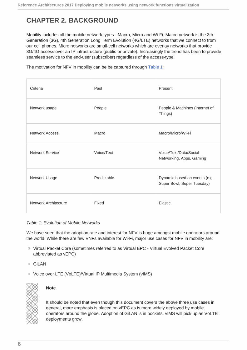
Mobility includes all the mobile network types - Macro, Micro and Wi-Fi. Macro network is the 3thGeneration (3G), 4th Generation Long Term Evolution (4G/LTE) networks that we connect to fromour cell phones. Micro networks are small-cell networks which are overlay networks that provide3G/4G access over an IP infrastructure (public or private). Increasingly the trend has been to provideseamless service to the end-user (subscriber) regardless of the access-type.
The motivation for NFV in mobility can be be captured through Table 1:
Criteria Past Present
Network usage People People & Machines (Internet ofThings)
Network Access Macro Macro/Micro/Wi-Fi
Network Service Voice/Text Voice/Text/Data/SocialNetworking, Apps, Gaming
Network Usage Predictable Dynamic based on events (e.g.Super Bowl, Super Tuesday)
Network Architecture Fixed Elastic
Table 1: Evolution of Mobile Networks
We have seen that the adoption rate and interest for NFV is huge amongst mobile operators aroundthe world. While there are few VNFs available for Wi-Fi, major use cases for NFV in mobility are:
Virtual Packet Core (sometimes referred to as Virtual EPC - Virtual Evolved Packet Coreabbreviated as vEPC)
GiLAN
Voice over LTE (VoLTE)/Virtual IP Multimedia System (vIMS)
Note
It should be noted that even though this document covers the above three use cases ingeneral, more emphasis is placed on vEPC as is more widely deployed by mobileoperators around the globe. Adoption of GiLAN is in pockets. vIMS will pick up as VoLTEdeployments grow.
Reference Architectures 2017 Deploying mobile networks using network functions virtualization
6

2.1. VIRTUAL PACKET CORE
Packet Core is the term used to refer to the part of the mobile network where the 3GPP gatewayfunctions such as Service Gateway (SGW)/Packet Data Switch Network Gateway (PGW)/MobileManagement Entity (MME) (4G/LTE) and Service GPRS Support Node (SGSN)/Gateway GPRSSupport Node (GGSN)/Packet Data Serving Node (PDSN) (3G) reside. A virtualized instance ofpacket core is referred to as Virtual Packet Core(VPC). Mobile Gateways get deployed differentlybased on requirement/function:
Virtual Evolved Packet Core is when a mobile operator who may have a 3G core has decided tostart offering 4G/LTE service and is building an evolved packet core. In this case typically most ofthe functions listed above may be virtualized - PGW, SGW, MME, PCRF, FW, Router, DPI,Switches, LB. This use case is typically for operators who are building a brand new mobilepacket core or upgrading and want to take the virtualization route rather than to invest in purposebuilt hardware. This also covers Trusted Wireless Local Area Network (WLAN) Access Gateway(TWAG)/Trusted WLAN AAA Proxy (TWAP) for Wi-Fi termination from trusted networks andEvolved Packet Data Gateway (EPDG) case which is responsible for terminating WiFiconnections from untrusted networks. It should be noted that the untrusted (EPDG) casetypically uses IPSec and encryption which could have a higher compute demand of the NFVInfrastructure (NFVi) (This is typically performed in hardware).
Enterprise Overlay Services/Enterprise Access Point Name (APN - A private instance for anenterprise customer). Mobile Network Operators (MNOs) offer dedicated APN services to largeenterprises. The services offered for these enterprise APNs vary from simply having dedicatedgateways to having additional security, custom QoS, VPN services to connect end-points toenterprise hub locations, Enterprise Billing and other value added services. Typically, creatingenterprise APNs means having a dedicated GGSN/PGW while other nodes that constitute themobile packet core may be shared or dedicated based on the design and deployment. Anexample of enterprise APN may be a packaging and logistics company like FedEx who maychoose to have their own APN where their mobile devices connect. By connecting to FedEx APNthese devices will automatically inherit certain connectivity (e.g. to FedEx Corp Cloud), havecertain services enabled (firewall, NAT) etc.
D-Core/Mobile Virtual Network Operators (MVNO) offer mobile services using parts of the actualnetwork that is owned and operated by MNOs. D-Core stands for Dedicated Core where a MNOoffers a mobile packet core per network instance per customer. For example, if a large logisticscompany needs to have their own mobile network, they can buy radio (air-time) from one ormore MNOs and use a dedicated core which usually is a virtual packet core (VPC) instancecreated for the logistic company.
Public Safety - During major events such as Republican National Convention (RNC) it iscommon to create a local channel for communication amongst all public safety factions - police,fire, medics etc. Nowadays this could be standing up a specialized 4G network for the duration ofthe event. This could be done in one of many ways - 4G in a box on a truck, temporarydatacenter setup at the venue or in the cloud. Regardless of the choice the main point to benoted is that this network is temporary and lives for the period of the event. Although purposebuilt hardware can also be used they have a huge footprint in terms of real estate, power,cooling and simply difficult to manage and operate. Virtual Packet Core (VPC) lends itselfperfectly for such an application
Machine to Machine/Internet of Things (IoT) - Machine to Machine(M2M) is another applicationthat requires dedicated gateways to be setup per M2M instance. M2M traffic tends to be sparseand have lower throughput while having a higher session count requirement. Adding thesegateways based on consumption and keeping it elastic makes M2M a classic use-case for VPC.A more successful and visible M2M/IoT use-case is “Connected Cars” which has been deployedsuccessfully by major mobile operators in North America
CHAPTER 2. BACKGROUND
7

2.2. GILAN
Mobile Packet Core networks can be viewed as having two connections - Radio network or wirelessside where the subscribers connect from and the Internet facing side. The Internet facing side of thenetwork in a 3G network is labelled as “Gi” interface (referred to as “SGi” in a 4G/LTE/EPCnetwork). IP services such as Firewall (FW), Network Address Translation (NAT), Deep PacketInspection (DPI), Parental Control, Video and Web optimization reside on the Gi or SGi interfacesafter leaving the gateway towards the Internet.
Depending on the APN and the services being offered, mobile operators are looking to createdynamic chains of these services. For e.g. when a subscriber roams from a 4G/LTE coverage areato a 3G coverage area, if they are watching video, their viewing experience may become degradeddue to network congestion. In such situations, the mobile operator would like to dynamically applyvideo optimization (transsizing and transcoding) to keep the user experience consistent. This abilityto dynamically apply different functions to the subscriber traffic is referred to as “Service Chaining”(https://datatracker.ietf.org/wg/sfc/documents/). Software Defined Networking (SDN) capabilities ofprogrammable APIs and actual use of SDN controllers (policy aware) in conjunction with NFV(ability to create capacity on the fly) makes it possible to deploy such features/functions inproduction. The operational nightmare of creating the permutations and combinations of all thesefunctions when overlaid with subscriber policy and intelligence (Location Based Services) made itimpossible to deploy prior to NFV/SDN.
2.3. VOLTE
LTE is an “All-IP” network. This allows applications such as voice that was traditionally analog to beoffered as Voice over IP (VoIP). VoIP in an LTE network is referred to as Voice over LTE or VoLTEfor short. VoLTE has service function chains that offer different functions such as Session BorderController (SBC), Call Session Control Function (CSCF) etc., which are being virtualized to fit intothe NFV model.
Reference Architectures 2017 Deploying mobile networks using network functions virtualization
8
CHAPTER 3. ETSI
European Telecommunications Standards Institute(ETSI) is a standards body that is responsible foror desires to standardize the NFV architecture. Telecoms/SPs around the world as well as all majornetwork equipment manufacturers have representation at ETSI.
It is important to understand that ETSI provides a framework and not necessarily a strict standardthat should be followed by all vendors. More details about ETSI/NFV can be found athttp://www.etsi.org/technologies-clusters/technologies/nfv.
Figure 1 shows the NFV architectural framework as defined by ETSI. The figure has componentsthat make up the NFV on the left such as NFV Infrastructure(NFVI), VNF etc and the Managementand Orchestration (MANO) sitting on the right. ETSI/NFV defines all aspects of the architectureincluding:
NFVI - NFV Infrastructure: NFVI is the infrastructure that includes the compute (servers), storageand networking as well as the hypervisors that offers the virtualization. It is an abstraction thatallows us to simply install VNFs without having to worry about the details of the underlyinghardware. NFVI forms the foundation for the NFV stack. It supports multi-tenancy and ismanaged by the Virtual Infrastructure Manager (VIM). In deployments today the VIM is
OpenStack®. The virtualization layer is typically KVM.
MANO - NFV Management and Orchestration: One of the main goals of NFV is to decouple thehardware and the software. This decoupling requires additional layer of management. Thismanagement is addressed by the MANO spec from ETSI. MANO defines the VNFM - VirtualNetwork Function Manager which manages the lifecycle of the VMs/VNFs either by interactingdirectly with the VMs/VNFs or through Element Management System (EMS) that work withvarious VMs/VNFs. The other important component defined by MANO is the Orchestrator alsoknown as NFVO. NFVO is the overall orchestrator that interfaces with various databases andsystems including OSS/BSS on the north and with the VNFM on the south. If the NFVO wants tocreate an instance of a VNF/VM, it requests to VNFM to create one such instance.
NFV Software Architecture - This section deals with the transition of network functions fromhardware-based to software-based. It describes software architecture that can be leveragedwhen decoupling software from the hardware.
NFV Reliability and Availability - as the name suggests deals with reliability and availability ofVNFs/VMs. There are a lot of challenges in making such a complex system resilient. It is a keyrequirement for all Telcos/SPs. The reliability and availability group studies the requirements andprovides guidelines of how they should be incorporated in NFV deployments.
NFV Performance and Portability - One of main goals of NFV is to support a framework that willallow existing industry network applications to be represented with their existing requirementsand characteristics. i.e The throughput, performance, scale attributes of these network functions.Additionally they should be portable, meaning we should be able to instantiate these VMs/VNFsin a cloud.
NFV Security - Security of the cloud that houses mission critical applications of the SPs and theircustomers is of paramount importance. NFV security group was formed to focus on this aspect ofNFV. Telcos are known to require customer aware (Policy, Authentication etc) VNFs to run in aseparate DMZ and other non-customer-aware VNFs to be zoned off and have firewallsseparating the zones. NFV architecture has to take into account such requirements from telcos.
CHAPTER 3. ETSI
9

Figure 1: ETSI/NFV Architectural Framework (Source:ETSI GS NFV 002 V1.1.1 (2013-10))
Figure 2 shows a mapping of Red Hat® products to the ETSI/NFVI architecture.
Reference Architectures 2017 Deploying mobile networks using network functions virtualization
10

Figure 2: Red Hat product mapping to ETSI NFV
3.1. NFVI
The high-level goals of NFV is to abstract the compute, storage and network from the application -decoupling the software functions from the hardware. At an architectural level we should not beconcerned about what type of compute, storage or networking is being used. However,characteristics of each of these components need to be addressed in order to elicit the most optimalperformance that is required by Telcos in the NFV architecture.
Compute
Storage
Network
3.1.1. Compute
From a compute perspective it is important for a VNF to be able to clearly specify the “quantity” and“quality” required by that VNF of the underlying NFVI in order to be able to function optimally
Often NFV performance optimizations are required that include but not limited to:
CPU Pinning
Huge pages
CHAPTER 3. ETSI
11

NUMA nodes
NOVA scheduler
Realtime Kernel-based Virtual Machine (KVM)/Kernel (RT-KVM)
Tweaking/disabling overcommit?
3.1.2. Storage
Storage can be local or cloud storage. Most VNFs are new. We have not had years of experience tobe able to quantify and qualify the storage characteristics such as IOPS (Input/Output OperationsPer Second), Latency etc. As a result, VNF vendors may tend to be conservative and design theirVNFs assuming local storage. Although we have seen mostly local block storage being used(Cinder) as well as Ceph, it is too early to be able to create benchmarks for storage as it relates toNFV. However, NFV architecture should discuss the pros and cons of different models.
Red Hat OpenStack Platform supports storage plug-ins including Cinder. This allows 3rd partystorage to be directly integrated into OpenStack. This is very important as many Telcos may havebeen using storage from storage vendors (EMC, NetApp and others). Certified plug-ins for Cindercan be found at: https://access.redhat.com/articles/1535373
3.1.3. Network
Within NFV, the networking can get fairly convoluted because of the nesting nature of what is beingconducted. NFV architecture should discuss the various models and the pro & cons of using eachtype and their recommended usage. The following network topics will be discussed as relevant tomobile virtualization:
Provider networks
Tenant networks
Flat networks
VLANs
VXLANs
PCI Passthrough
Single Root Input/Output Virtualization (SR-IOV)
Data Plane Development Kit (DPDK)
Commercial SDNs using Neutron plugins
Reference Architectures 2017 Deploying mobile networks using network functions virtualization
12
CHAPTER 4. MOBILE ARCHITECTURES
4.1. VEPC DEPLOYMENT MODELS
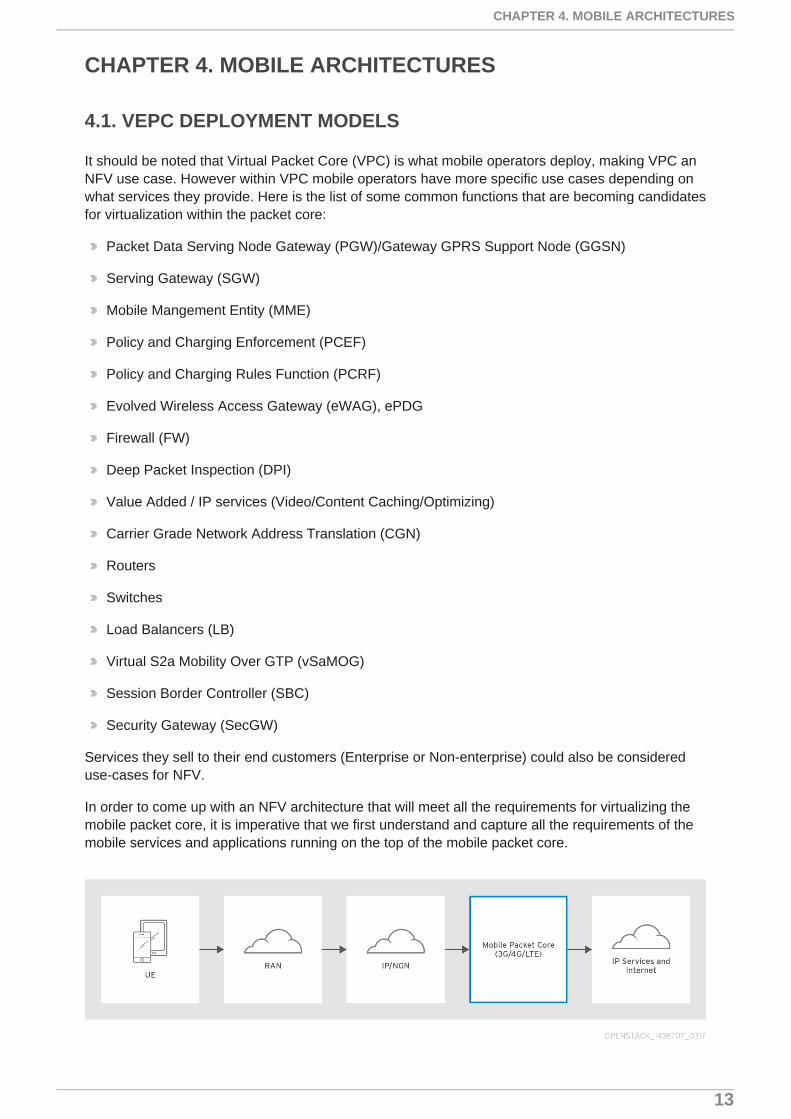
It should be noted that Virtual Packet Core (VPC) is what mobile operators deploy, making VPC anNFV use case. However within VPC mobile operators have more specific use cases depending onwhat services they provide. Here is the list of some common functions that are becoming candidatesfor virtualization within the packet core:
Packet Data Serving Node Gateway (PGW)/Gateway GPRS Support Node (GGSN)
Serving Gateway (SGW)
Mobile Mangement Entity (MME)
Policy and Charging Enforcement (PCEF)
Policy and Charging Rules Function (PCRF)
Evolved Wireless Access Gateway (eWAG), ePDG
Firewall (FW)
Deep Packet Inspection (DPI)
Value Added / IP services (Video/Content Caching/Optimizing)
Carrier Grade Network Address Translation (CGN)
Routers
Switches
Load Balancers (LB)
Virtual S2a Mobility Over GTP (vSaMOG)
Session Border Controller (SBC)
Security Gateway (SecGW)
Services they sell to their end customers (Enterprise or Non-enterprise) could also be considereduse-cases for NFV.
In order to come up with an NFV architecture that will meet all the requirements for virtualizing themobile packet core, it is imperative that we first understand and capture all the requirements of themobile services and applications running on the top of the mobile packet core.
CHAPTER 4. MOBILE ARCHITECTURES
13
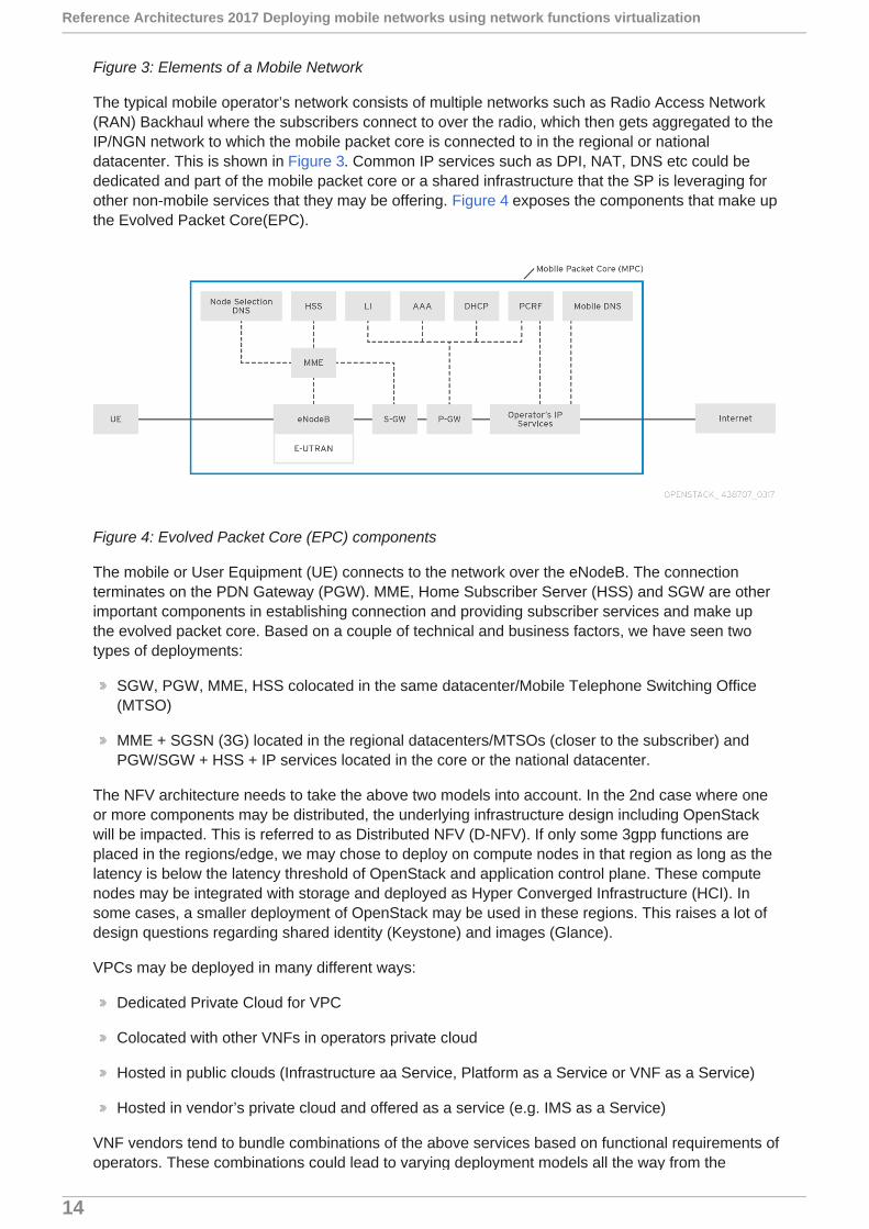
Figure 3: Elements of a Mobile Network
The typical mobile operator’s network consists of multiple networks such as Radio Access Network(RAN) Backhaul where the subscribers connect to over the radio, which then gets aggregated to theIP/NGN network to which the mobile packet core is connected to in the regional or nationaldatacenter. This is shown in Figure 3. Common IP services such as DPI, NAT, DNS etc could bededicated and part of the mobile packet core or a shared infrastructure that the SP is leveraging forother non-mobile services that they may be offering. Figure 4 exposes the components that make upthe Evolved Packet Core(EPC).
Figure 4: Evolved Packet Core (EPC) components
The mobile or User Equipment (UE) connects to the network over the eNodeB. The connectionterminates on the PDN Gateway (PGW). MME, Home Subscriber Server (HSS) and SGW are otherimportant components in establishing connection and providing subscriber services and make upthe evolved packet core. Based on a couple of technical and business factors, we have seen twotypes of deployments:
SGW, PGW, MME, HSS colocated in the same datacenter/Mobile Telephone Switching Office(MTSO)
MME + SGSN (3G) located in the regional datacenters/MTSOs (closer to the subscriber) andPGW/SGW + HSS + IP services located in the core or the national datacenter.
The NFV architecture needs to take the above two models into account. In the 2nd case where oneor more components may be distributed, the underlying infrastructure design including OpenStackwill be impacted. This is referred to as Distributed NFV (D-NFV). If only some 3gpp functions areplaced in the regions/edge, we may chose to deploy on compute nodes in that region as long as thelatency is below the latency threshold of OpenStack and application control plane. These computenodes may be integrated with storage and deployed as Hyper Converged Infrastructure (HCI). Insome cases, a smaller deployment of OpenStack may be used in these regions. This raises a lot ofdesign questions regarding shared identity (Keystone) and images (Glance).
VPCs may be deployed in many different ways:
Dedicated Private Cloud for VPC
Colocated with other VNFs in operators private cloud
Hosted in public clouds (Infrastructure aa Service, Platform as a Service or VNF as a Service)
Hosted in vendor’s private cloud and offered as a service (e.g. IMS as a Service)
VNF vendors tend to bundle combinations of the above services based on functional requirements ofoperators. These combinations could lead to varying deployment models all the way from the
Reference Architectures 2017 Deploying mobile networks using network functions virtualization
14
number of VMs to HA, scale, traffic mix and throughput requirements.
Depending on the type of service(s) being deployed the VNFs may be deployed in one of thefollowing ways:
Lightweight deployments that uses All-in-One (AIO) OpenStack that typically runs on a singleserver
If multiple functions are required, multiple servers are deployed, each running the VNF. Thisis shown in Figure 8.
Runs on blade or rack-mount servers
Suitable for cloud deployment on private, public or hybrid-clouds
Running on pre-bundled, fixed configuration blade-servers over KVM.
Easy to deploy
Easy to migrate as an extension of existing purpose-built hardware
Tested and certified with specific versions of Red Hat Enterprise Linux®/KVM and VPCsoftware
Easy to support (few, fixed, and known components)
Full HA Red Hat OpenStack Platform deployment comprising of multiple servers (blades or rack-mount).
Typically used when building entire packet core with all functions as a replacement forhardware-based packet cores
4.2. GILAN
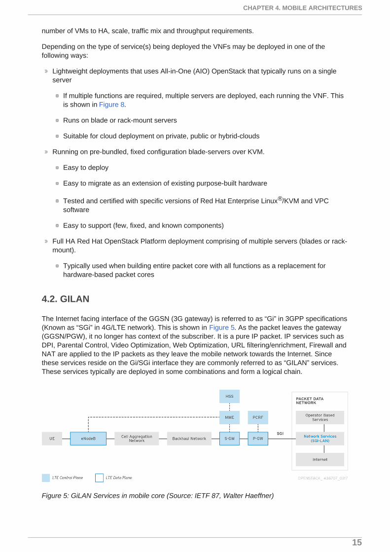
The Internet facing interface of the GGSN (3G gateway) is referred to as “Gi” in 3GPP specifications(Known as “SGi” in 4G/LTE network). This is shown in Figure 5. As the packet leaves the gateway(GGSN/PGW), it no longer has context of the subscriber. It is a pure IP packet. IP services such asDPI, Parental Control, Video Optimization, Web Optimization, URL filtering/enrichment, Firewall andNAT are applied to the IP packets as they leave the mobile network towards the Internet. Sincethese services reside on the Gi/SGi interface they are commonly referred to as “GILAN” services.These services typically are deployed in some combinations and form a logical chain.
Figure 5: GiLAN Services in mobile core (Source: IETF 87, Walter Haeffner)
CHAPTER 4. MOBILE ARCHITECTURES
15

Most mobile operators offer some variation of GiLAN services but restrict it to APN granularity ratherthan subscriber level. This is because traditional GiLAN services required physical connections toform the chain.
Today’s solution uses Software Defined Networking (SDN) to create logical chains between GiLANelements. The actual application runs in a virtual environment typically on top of OpenStack ratherthan purpose built appliances. This offers a huge advantage - applications can scale based ondemand and conversely shrink. A classic example of this would be when people return from workand turn on their TV or Over The Top (OTP) video (Netflix, Amazon etc). This creates a surge intraffic and creating a demand on GiLAN elements.
From an infrastructure point of view, GiLAN will closely resemble the vEPC VNF. It will have thesame requirements of Orchestration, VNF lifecycle management, performance and security.Additionally GiLAN will require:
Metering capability to determine the resource usage * Ability to grow and shrink based ondemand. This may be done completely automatically in theory. However, mobile operators preferto have manual control of resource allocation. * Service Function Chaining (SFC) - SFC isdefined by the Internet Engineering Task Force (IETF) working group. Related documents canbe found at https://datatracker.ietf. org/wg/sfc/documents. SFC may use Network ServiceHeader (NSH) or may be based on Multi Protocol Label Switching (MPLS). OpenStacknetworking will need to support SFC or may be an overlay function over OpenStack.
4.3. VOICE OVER LTE (VOLTE)/IP MULTIMEDIA SERVICES (IMS)
VoLTE utilizes the IP Multimedia Services (IMS) in the core of the mobile network. IMS is also usedby SPs to offer non-mobile voice service including High Definition (HD) Voice, Video Calling, Wi-FiCalling, Messaging Services etc. IMS consists of several components that traditionally werehardware appliances that got virtualized and deployed in the cloud by NEPs and Telcos. Theseinclude:
Call Session Control Function (CSCF)
Media Gateway Controller
Session Border Control
Application Servers
Policy and Charging Rules Function
Diameter and Radius Servers
Home Subscriber Server
Figure 6 shows details of the IMS architecture. From a NFV and virtualized IMS point of view, therequirements would be a very similar to vEPC application. There are no special SFC or dynamicgrown and shrink requirements. However, attention has to be paid to packet size and latency as thisapplication is primarily used for delivery high quality voice for VoLTE and non-mobile voice andmultimedia services.
Reference Architectures 2017 Deploying mobile networks using network functions virtualization
16
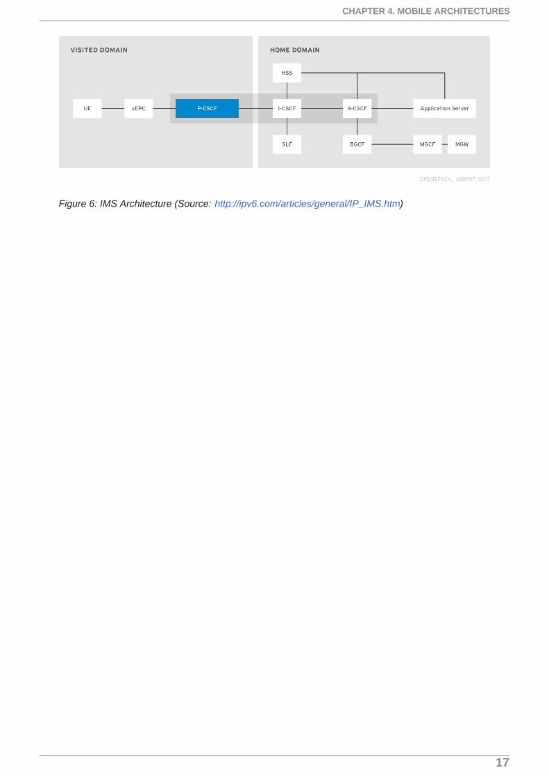
Figure 6: IMS Architecture (Source: http://ipv6.com/articles/general/IP_IMS.htm)
CHAPTER 4. MOBILE ARCHITECTURES
17

CHAPTER 5. HIGH AVAILABILITY
Two key requirements of Telcos for any application are performance and high availability (HA). Inthe multi-layered world of NFV, HA cannot be achieved only at the infrastructure layer. HA needs tobe expansive and overarching in all aspects of design including hardware support, following bestpractice for layer 2 and layer 3 design of the underlay network, at the OpenStack level and last butnot the least at the application layer. ETSI NFV (ETSI GS NFV-REL 001 V1.1.1 (2015-01)) defines“Service Availability” rather than talking in terms of five 9s. “At a minimum, the Service Availabilityrequirements for NFV should be the same as those for legacy systems (for the same service)”. Thisrefers to the end-to-end service (VNFs and infrastructure components).
5.1. GEO-REDUNDANCY
vEPC components such as SGW and PGW may be placed either centrally at the core datacenter(National Datacenter) or regionally to serve the local cell sites or exit points. The eNodeBs arecollocated with the tower (Cell Site). In a 4G/LTE network, deciding which SGW (Ingress into thenetwork) to use is typically based on subscriber location (Tracking Area Code). The subscriberconnection terminates on the PGW. The decision of which PGW to assign to the subscriber dependson the context (APN) and other factors. The actual assignment may be done based on DNS lookup.This is shown in Figure 7.
Because of this reason, the SGW and the PGWs could be placed in regional datacenters closer tothe service they need to provide. This approach is taken by many operators. However, in manydeployments, the gateways, MME and other functions may be collocated in a centralized nationaldata-center. GiLAN and IMS services are typically deployed only in the core of the mobile network.
Regardless of which way it is deployed, it is important to have redundancy built in at a datacenterlevel. Additionally geo-redundancy should also be factored in so that similar functions can beleveraged from other datacenters in case of a catastrophic failure at one of the datacenters. It shouldbe noted that apart from using traditional routing to reroute traffic to the gateways/elements thatbecame active due to the failure of the primary, SDN and Software Defined Wide Area Network (SD-WAN) technology could be employed to reprogram the underlying layer 2 and layer 3 networks toprovide the appropriate level of bandwidth and functionality needed.
Figure 7: Datacenter redundancy and deployment of vEPC
5.2. CHASSIS/BLADE REDUNDANCY
For lightweight All In One (AIO) deployments (shown in Figure 8, common datacenter designpractice should be followed. Don’t place active and standby VNFs on the same chassis/host. Followdatacenter and cloud deployment best practices:
Blade Redundancy - DO NOT deploy active and standby instance of the same/related VNF onthe same host/blade
Reference Architectures 2017 Deploying mobile networks using network functions virtualization
18

Chassis Redundancy - DO NOT deploy active and standby instances of the same/related VNFon the same chassis
Rack Redundancy - DO NOT deploy active and standby instances of the same/related VNF onthe same rack/row
Figure 8: Lightweight, AIO VPC deployment
Multi-server deployments regardless of whether they run on top of KVM or a full fledged OpenStackdeployed in HA mode should follow the above mentioned Chassis/Blade redundancy best practices.In addition, HA best practices should be followed at the application layer. Typically, VPC VNFs havededicated VMs acting as Control Modules which handles control traffic and the data traffic istypically handled by switching or Service Modules. Depending on whether a single chassis is beingdeployed or multiple chassis are being deployed, it will be important to place the control modulesand service modules to allow for high availability and redundancy.
Figure 9: Single Chassis deployment of control and switching modules.
Figure 9 shows deployment of VPC VNF on a single blade server chassis. Multiple blade server willdistribute the control modules (CMs) across the chassis so that each chassis to mitigate failure. Thenumber of control and switching modules and their deployment best practices will come from theVNF vendors. This can be seen in Figure 10.
CHAPTER 5. HIGH AVAILABILITY
19

Figure 10: Multi-chassis VNF HA Deployment
GiLAN elements that form logical service chains (SFC), can be deployed the following manner:
All VNFs required to form a logical service function chain is deployed on each server. In thismodel, the server and its resources become one logical deployment unit for each service chain.The advantage of this is that the operation becomes simple as deployment is uniform. To scaleyou simply add more servers. The disadvantage is that some elements of the SFC tend to getmore utilized than others and tend to become bottlenecks which means for example, eventhough a parental control VM may be at 30% utilization (because it is only applied to childsubscribers), DPI may be at 90% utilization because it is very CPU intensive.
Alternately, VNFs are deployed based on their resource requirement of the server and managedat a higher level by the VNF Manger (VNFM) or NFV Orchestrator (NFVO). In this scenario, if aVNF is deemed non-responsive or additional unit of the VNF needs to be instantiated, anappropriate server that matches the resource requirements of the VNF. If such as server is notavailable, the entire service chain cannot be deployed.
IMS elements will be similar to GiLAN in the sense that they are made up of some discrete elementsrequired to perform the various functions. Care has to be taken to ensure that hardware or networkfailure does not isolate functions. Basic principles of HA and best practices apply to for deploymentof all virtual mobile network VNFs.
5.3. DATACENTER TOPOLOGY (UNDERLAY)
Datacenter topologies have changed and evolved over time. Prior approach was three layered andconsisted of Access, Aggregation(Distribution) and Core layers (Figure 11.) Access layers typicallyconsisted of layer 2 switches where the servers connected. These switches connected into layer2/layer 3 switches which were then connected up to pure layer 3 routers that formed the core.
Reference Architectures 2017 Deploying mobile networks using network functions virtualization
20
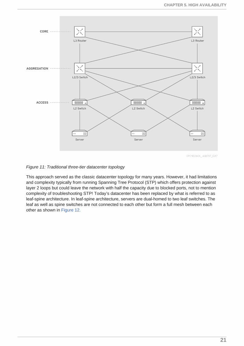
Figure 11: Traditional three-tier datacenter topology
This approach served as the classic datacenter topology for many years. However, it had limitationsand complexity typically from running Spanning Tree Protocol (STP) which offers protection againstlayer 2 loops but could leave the network with half the capacity due to blocked ports, not to mentioncomplexity of troubleshooting STP! Today’s datacenter has been replaced by what is referred to asleaf-spine architecture. In leaf-spine architecture, servers are dual-homed to two leaf switches. Theleaf as well as spine switches are not connected to each other but form a full mesh between eachother as shown in Figure 12.
CHAPTER 5. HIGH AVAILABILITY
21

Figure 12: Leaf and spine datacenter topology
Leaf-spine can be either layer 2 or layer 3. In a layer 2 approach, all connections are active/active.In leaf-spine architecture, Transparent Interconnection of Lots of Links (TrILL) or Shortest PathBridging (SPB) are used instead of STP. However, leaf-spine architecture with layer 3 has theadvantage of simplicity. In such a layer-3-only network, hosts may run a routing agent that willannounce /32 to the leafs. Equal Cost MultiPath (ECMP) is used for evenly distributing traffic acrosslinks. It is possible to use Open Shortest Path First (OSPF) or Border Gateway Protocol (BGP) todistribute routes across the datacenter fabric. BGP is becoming a favorite with new enhancementssuch as BGP unnumbered which makes configuration a breeze. BGP is also proven to be highlyscalable and reliable as it has been carrying Internet Routes for decades now. It should be notedhowever, that OpenStack networking is typically layer 2 based (VLAN, VxLAN). Most OpenStackdeployments including for NFV/virtual mobile networks are layer 2 based. Red Hat OpenStackPlatform uses the Neutron networking service to create and deploy tenant networks. It should benoted that routed (layer 3) leaf-spine deployments are not currently supported by OpenStackPlatform director. Director installations have the following pre-defined networks(https://access.redhat.com/documentation/en/red-hat-openstack-platform/10/paged/director-installation-and-usage/chapter-3-planning-your-overcloud):
Intelligent Platform Management Interface (IPMI)
Provisioning
Internal API
Tenant
Storage
Storage Management
Reference Architectures 2017 Deploying mobile networks using network functions virtualization
22
External
Floating IP
Management
Each of these networks will be mapped to IP subnets and typically VLANs. Details of networking forvEPC is discussed under the networking section.
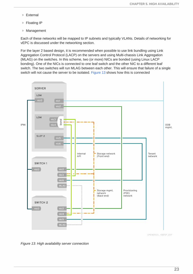
For the layer 2 based design, it is recommended when possible to use link bundling using LinkAggregation Control Protocol (LACP) on the servers and using Multi-chassis Link Aggregation(MLAG) on the switches. In this scheme, two (or more) NICs are bonded (using Linux LACPbonding). One of the NICs is connected to one leaf switch and the other NIC to a different leafswitch. The two switches will run MLAG between each other. This will ensure that failure of a singleswitch will not cause the server to be isolated. Figure 13 shows how this is connected
Figure 13: High availability server connection
CHAPTER 5. HIGH AVAILABILITY
23
NIC 0 on all servers is or Intelligent Platform Management Interface (IPMI) that is used to configurethe servers and to console into them. NIC1 is for Out of band management (OOB). That is used toconnect to the servers directly over IP.
NICs 3 & 4 of the server carry Internal traffic including storage, internal API, etc. They are bonded.NIC 3 connects up to the switch on the top, whereas NIC 4 connects to the bottom switch. The twoswitches run MLAG. The bonded NIC will trunk all the VLANs for internal traffic. Similarly NICs 5 & 6may be bonded to carry external traffic (accessible to the outside world). It should be noted however,that current deployments of vEPC use Single Root Input Output Virtualization (SR-IOV) for datapath(data plane) and in order to use SR-IOV, bonding should not be done at the host level. NIC bondingat guest VM/VNF level is however supported for SR-IOV and can be be used by VNFs to mitigaterisk of uplink switch failure.
Network Equipment Providers (NEPs) are looking to move away from SR-IOV based vEPC solutionin the future and are looking to use Open Virtual Switch (OVS) + Data Plane Development Kit(DPDK) as their fast datapath. NIC bonding at the host level will be supported for OVS+DPDK thusallowing NICs 5 & 6 to be bonded as well.
It should be noted that if another pair of NICs is available, it is a good idea to split off the storagenetwork to have its own bond if we are using a CEPH cluster as our storage backend. If we areusing external/cloud storage this is not required.
5.4. NFVI (OPENSTACK) AVAILABILITY
Red Hat OpenStack Platform offers several features to support HA. These features are supportedand can be deployed using Red Hat OpenStack director. Since OpenStack control plane andservices mostly reside on the controller nodes, HA features are targeted towards the controllernodes. OpenStack HA features that are employed for HA are:
Pacemaker is responsible for lifecycle management of services within the HA cluster. It ensuresthe services are available. If it deems the service as “not available” either because the serviceitself went down or the node went down, Pacemaker can restart the service, reboot the node andif all else fails, remove the node from the cluster and eventually try to restore the service.HAProxy runs on all controller nodes and is responsible for load balancing traffic to the servicesrunning on these nodes.
Galera - Red Hat OpenStack Platform uses the MariaDB Galera Gluster to manage databasereplication.
OpenStack HA may be deployed in one of two modes:
Active/Active: In this mode, services are running on multiple controller nodes at the same time.HAProxy is used to load balance and distribute traffic. These services are managed by systemd.
Active/Passive: In this mode, the service is active only on one controller node. HAProxy directsthat traffic to that node. These services are managed by pacemaker.
More details on Red Hat OpenStack Platform HA can be obtained in the document“UNDERSTANDING RED HAT OPENSTACK PLATFORM HIGH AVAILABILITY” which is availableon the Red Hat customer portal at http://access.redhat.com. Additionally, it is important to note thatwith Red Hat OpenStack Platform 10 release (Newton), another HA component is introduced knownas “systemd”. Some services will be managed by Pacemaker whereas others will be managed bysystemd. Also there will be common controllers vs. dedicated controllers. These will be discussed inrelease-specific addendums to this architecture document where release-specific features and theirconfigurations will be covered.
Reference Architectures 2017 Deploying mobile networks using network functions virtualization
24
vEPC and virtual mobile NEPs in general expect the VIM (OpenStack) to be running in full HA modeas vEPC could be running mission critical services such as 911 and typically hosts millions ofsubscribers per instance.
5.5. APPLICATION LAYER HA
NEPs have had resilience and high availability in mind through design and deployment of virtualizedmobile networks (vEPC, GiLAN and IMS). The purpose built hardware had HA features built into theproducts from the get-go all the way from the backplane design, deployment of control modules andservice modules (data plane processors) to port redundancy to in service software upgrades. Withthe advent of virtualized solutions (NFV), the control and service modules became VMs that use the“Internal Networks” created in OpenStack to communicate with each other. However, the applicationlogic that existed to manage availability and detect failure of service modules continue to exist in thevirtualized solution as well. Control modules typically keep tab of the deployed and available servicemodules, use some load-balancing criteria to distribute traffic and assign service modules tosubscriber flows. N+1 or N+N redundancy depending on design makes certain service modulesactive while one or more service modules may serve as standby, thus allowing these standbymodules to take over upon failure of an active service module. Since typically these applications usesome sort of heart-beat mechanism to keep track of the service module liveliness, whether they runin a virtual environment or not becomes immaterial. Additionally, session recovery between physicalchassis will continue to be supported in the virtual environment. For this typically, some controlplane protocol is used to determine active and standby nodes, failure detection and state changefrom standby to active based on some failure condition.
5.5.1. Host Aggregates and Availability Zones
NEPs who provide mobility VNFs require creation of Availability Zones in OpenStack. This is used toensure certain VMs or groups of VMs land on certain compute nodes. This could be based onavailability of local disk within that zone, it could be based on hardware profiles (nodes that supportNUMA, CPU pinning, or have certain type of NICs that support SR-IOV). The application may alsochose to place VMs in different zones to achieve load-sharing and mitigate risk during failure.
5.5.2. Shared File System
Shared file system can be used to store configurations of VNFs to be able to mirror the functions thatis perhaps located in a geo-redundant datacenter.
5.5.3. Instance HA
Previous sections discussed how OpenStack services can be protected using pacemaker and othertools. However, it is also important to keep track of VNFs that run as VMs on the top of OpenStackand recover them in case of failure. This is referred to as “Instance HA”. Instance HA is available inRed Hat OpenStack Platform 7 and later. It can be used for VNFs that are are not managed by theSVNFM (Specialized VNFM that is vEPC/GiLAN/IMS application aware).
CHAPTER 5. HIGH AVAILABILITY
25

CHAPTER 6. NETWORKING
Earlier networks typically required for Red Hat OpenStack Platform director during installation ofOpenStack was discussed. They are:
IPMI
Provisioning
Internal API
Tenant
Storage
Storage Management
External
Floating IP
Management
Figure 14 illustrates the typical OpenStack networking topology.
Reference Architectures 2017 Deploying mobile networks using network functions virtualization
26

Figure 14: Typical OpenStack Network Topology
Virtual mobile VNFs (vEPC, GiLAN & IMS) are considered complex VNFs that is made up of severalVMs, may contain its own Element Manager (EM) and typically consists of multiple networks.Different NEPs may call these networks by different names and may have have one or more ofeach type. For instance, vEPC will have networks for:
vEPC Management network (virtio): Used for management/Operations and Management (OAM)through floating IP addresses as well as for control traffic of vEPC itself. Keeping track ofliveliness of nodes/functions, application level session management, redundancy, error logging,recovery, auto-scaling etc. This is typically deployed as VX-LAN tenant network.
External/Internet (Typically virtio). This also deployed as VX-LAN tenant network.
Internal Traffic - Typically East-West Traffic, between control modules and switching modules.This network can get used the following:
Storage access
Inter-node communication by vEPC application
CHAPTER 6. NETWORKING
27

Control
Data plane (sometimes during failover)
OpenStack API traffic
If the vEPC (mobile) application is only passing control traffic on this network, it can beconfigured as VX-LAN tenant network that uses virtio. However, some NEPs may actuallychoose to send dataplane traffic on this network during failure of a service module. In suchcases, the NEP may chose to use SR-IOV provider network to optimize throughput.
Application traffic - This is actual North-South subscriber traffic. In the context of 3gpp it is theGTPu (User Plane) traffic. This network is typically designed to carry huge amounts of traffic.Most current deployments of vEPC use SR-IOV (Single Root Input Output Virtualization) to allowhigh throughput (close to 10G on a 10G port) with minimal latency. The SR-IOV networks aretypically created as provider networks in Openstack opposed to tenant network. An importantnote regarding SR-IOV ports is that they show up as Virtual Functions (VFs) on the guest VM.SR-IOV ports cannot be bonded using LACP at the host level. It is the responsibility of the VNFto bond/bundle two or more VNICs (Virtual Network Interface Cards) derived from VFs toachieve higher throughput beyond 10G or more typically to ensure high availability. This isachieved by mapping the PNICs (Physical NICs) of the SR-IOV ports to different datacenterswitches. This ensures that the guest VM continues to have connectivity if and when an uplinkswitch fails. Several NEPs are testing OVS-DPDK as an alternative datapath to SR-IOV as ithas several shortcomings which will be discussed later under the performance optimizationsection. With OVS-DPDK, bonding of Ethernet ports will be supported at host level similar towhat we can do with virtio.
6.1. NEUTRON PLUG-INS
NEPs may chose to use some commercial neutron plug-in instead of using OVS for OpenStacknetworking. This is supported by Red Hat OpenStack Platform and is done as a part ofcustomization during deployment of OpenStack at the Telco by the NEP or their partner.
Red Hat certified plug-ins for Neutron can be found at https://access.redhat.com/articles/1535373.Red Hat has a plethora of 3rd party plug-ins. Information regarding this can be found athttps://access.redhat.com/ecosystem.
6.2. IPV6 NETWORKING
Mobile operators deploy dual-stack IP networks. Whether IPv4 or IPv6 is used depends on the APN(Access Point Name) or context. Typically for LTE(Long Term Evolution), IPv6 is used for VoLTEAPN. Internet APN could use both IPv4 and IPv6. IPv4 is being maintained for backwardcompatibility as certain applications still don’t work with IPv6.
OpenStack Networking supports IPv6 tenant subnets in dual-stack configuration, so that projectscan dynamically assign IPv6 addresses to virtual machines using Stateless AddressAutoconfiguration (SLAAC) or DHCPv6. OpenStack Networking is also able to integrate with SLAACon your physical routers, so that virtual machines can receive IPv6 addresses from your existinginfrastructure. For more information, see Tenant Networking with IPv6.
Reference Architectures 2017 Deploying mobile networks using network functions virtualization
28

CHAPTER 7. STORAGE
Virtual mobile VNFs requires storage for the following:
Images (Glance)
Storing CDR (Call Data Records) used for billing
Video and Web caching
Logging data, core files, availability & performance statistics, files and snapshots useful fortechnical support and other stateful information
While some NEPs clearly recommend using fully redundant CEPH deployment for storage, mostwork with both local and cloud storage options as long as the storage can be provisioned anddeployed using OpenStack. Mobile VNFs are known to use Cinder and Glance OpenStack services:
For the Glance service, you need enough storage to provide the space needed to hold yourimages (such as qcow images that are perhaps a couple hundred MB and bootable installationISO images such as a 4GB Red Hat Enterprise Linux install image).
For the Cinder service, you need enough storage to provide the block storage needed for yourVMs to run. For our example, we started out with a 25GB NFS share for Glance and a 100GBNFS share for Cinder.
Both persistent and ephemeral storage may be requested and used by mobile applications.
Three types of storage solutions have been used in deployments:
Local storage - Early deployments using mostly rack-mount servers with local storage slots
Cloud storage - Storage provided by commercial storage vendors (EMC, NetApp etc.)
Ceph storage - Either external or part of Red Hat OpenStack Platform deployment using director.
Red Hat OpenStack Platform director creates a cloud environment called the Overcloud. Thedirector provides the ability to configure extra features for an Overcloud. One of these extra featuresincludes integration with Red Hat Ceph Storage. This includes both Red Hat Ceph Storage clusterscreated with the director or existing Ceph Storage clusters. This guide provides information forintegrating Red Hat Ceph Storage into your Overcloud through the director and configurationexamples. (https://access.redhat.com/documentation/en/red-hat-openstack-platform/10/paged/red-hat-ceph-storage-for-the-overcloud/)
For virtual mobile deployment, we recommend using OpenStack director installation to create theCeph cluster. The Ceph cluster is made up of two main components:
Ceph OSD (Object Storage Daemon) which is deployed on three dedicated Ceph nodes.Replication, rebalancing, recovery, monitoring and reporting functions are performed by OSDnodes.
Ceph Monitor maintains a master copy of Ceph storage map with the current state of the storagecluster. For virtual mobile deployment, we will use OpenStack controller nodes to host Cepmonitor function
This is shown in Figure 15.
CHAPTER 7. STORAGE
29

Figure 15: Ceph cluster for virtual mobile networks <<<
Reference Architectures 2017 Deploying mobile networks using network functions virtualization
30
CHAPTER 8. PERFORMANCE AND OPTIMIZATION
The fundamental business model for Communication Service Providers (CSPs) and Telcos is basedon providing mission critical applications to a large pool of subscribers with least amount of servicedisruption. Earlier we highlighted that there are two key requirements for NFV (others requirementsalso important). Performance and high availability. Although high availability was covered in anearlier section, it should not be construed as being a higher priority than performance. The need forhigh performance for CSPs and Telcos stems from the fact that they need to be able to support thehighest number of subscribers using the lowest amount of resources so as to maximize profits.Without being able to achieve very high throughputs that are comparable to what is achievable withpurpose built hardware solutions, this whole business model breaks down.
The journey began with using Linux bridges, virtio and OVS. As demand for higher performancegrew in NFV, PCI passthrough, SR-IOV, OVS with DPDK and Vector Packet Processing (VPP)were introduced to meet the demand. We cover each of them in the following sections and their usein vEPC. The higher performance requirement also applies to GiLAN when deployed becauseGiLAN is in the dataplane.
8.1. OPEN VSWITCH
Open vSwitch (OVS) is an open source software switch designed to be used as a vSwitch withinvirtualized server environments. OVS supports many of the capabilities you would expect from atraditional switch, but also offers support for “SDN ready” interfaces and protocols suchas OpenFlow and OVSDB. Red Hat recommends Open vSwitch for Red Hat OpenStack Platformdeployments, and offers out of the box OpenStack Networking (Neutron) integration with OVS.
Standard OVS (Figure 16) is built out of three main components:
ovs-vswitchd – a user-space daemon that implements the switch logic
kernel module (fast path) – that processes received frames based on a lookup table
ovsdb-server – a database server that ovs-vswitchd queries to obtain its configuration. Externalclients can talk to ovsdb-server using OVSDB protocol
When a frame is received, the fast path (kernel space) uses match fields from the frame header todetermine the flow table entry and the set of actions to execute. If the frame does not match anyentry in the lookup table it is sent to the user-space daemon (vswitchd) which requires more CPUprocessing. The user-space daemon then determines how to handle frames of this type and sets theright entries in the fast path lookup tables.
vEPC VNF has several supports several applications as we have discussed earlier - data,
voice and video. Each application has different tolerance to delay (latency), jitter and packet loss.This is summarized in Table 2. 3GPP specifies using AMR-NB (narrow band) codec for Voice overLTE (VoLTE). However, many operators also offer HD voice which uses AMR-WB. Actual codecsdeployed by operators vary. In general when it comes to frame loss. The voice applications requirefar less than 1% frame loss. The closer to zero frame loss the better.
OVS has several ports: outbound ports which are connected to the physical NICs on the host usingkernel device drivers, and inbound ports which are connected to VMs. The VM guest operatingsystem (OS) is presented with vNICs using the well-known VirtIO paravirtualized network driver.
CHAPTER 8. PERFORMANCE AND OPTIMIZATION
31

Figure 16: Standard OVS architecture; user-space and kernel space layers
While some users may find acceptable performance numbers with the standard OVS, it was neverdesigned with NFV in mind and does not meet some of the requirements we are starting to see fromVNFs. Thus Red Hat, Intel, and others have contributed to enhance OVS by utilizing the Data PlaneDevelopment Kit (DPDK), boosting its performance to meet NFV demands or entirely bypass OVSusing PCI passthrough or SR-IOV.
With traditional cloud applications such as Wordpress, Apache web servers and databases, theapplications were not network centric. One could get away with the performance delivered by virtioand then stacking VMs to scale the number of users (subscribers). For NFV workloads this is nolonger adequate. In order to improve network performance for VMs initial approach was to use PCIpassthrough.
Mobile VNFs could still use standard OVS for management network etc that may not require veryhigh throughput.
8.2. PCI PASSTHROUGH
Through Intel’s VT-d extension (IOMMU for AMD) it is possible to present PCI devices on the hostsystem to the virtualized guest OS. This is supported by KVM (Kernel-based Virtual Machine). Usingthis technique it is possible to provide a guest VM exclusive access to a NIC. For all practicalpurposes, the VM thinks the NIC is directly connected to it.
Reference Architectures 2017 Deploying mobile networks using network functions virtualization
32
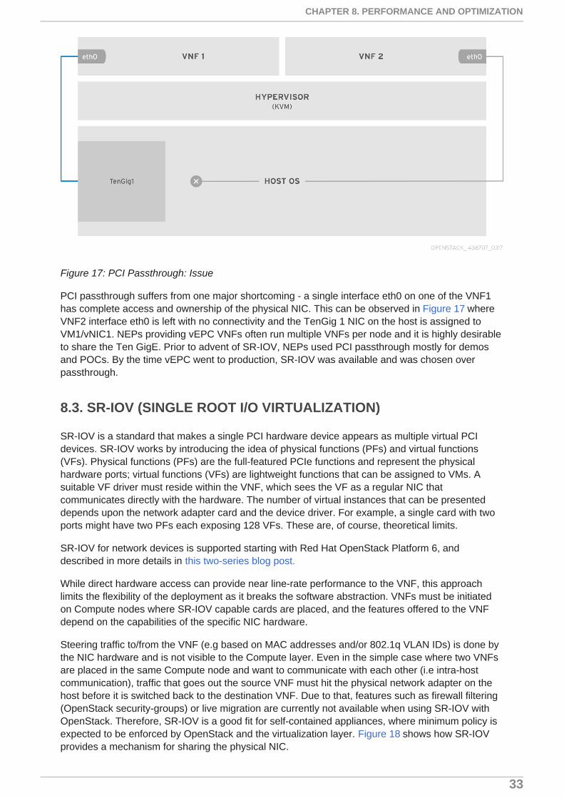
Figure 17: PCI Passthrough: Issue
PCI passthrough suffers from one major shortcoming - a single interface eth0 on one of the VNF1has complete access and ownership of the physical NIC. This can be observed in Figure 17 whereVNF2 interface eth0 is left with no connectivity and the TenGig 1 NIC on the host is assigned toVM1/vNIC1. NEPs providing vEPC VNFs often run multiple VNFs per node and it is highly desirableto share the Ten GigE. Prior to advent of SR-IOV, NEPs used PCI passthrough mostly for demosand POCs. By the time vEPC went to production, SR-IOV was available and was chosen overpassthrough.
8.3. SR-IOV (SINGLE ROOT I/O VIRTUALIZATION)
SR-IOV is a standard that makes a single PCI hardware device appears as multiple virtual PCIdevices. SR-IOV works by introducing the idea of physical functions (PFs) and virtual functions(VFs). Physical functions (PFs) are the full-featured PCIe functions and represent the physicalhardware ports; virtual functions (VFs) are lightweight functions that can be assigned to VMs. Asuitable VF driver must reside within the VNF, which sees the VF as a regular NIC thatcommunicates directly with the hardware. The number of virtual instances that can be presenteddepends upon the network adapter card and the device driver. For example, a single card with twoports might have two PFs each exposing 128 VFs. These are, of course, theoretical limits.
SR-IOV for network devices is supported starting with Red Hat OpenStack Platform 6, anddescribed in more details in this two-series blog post.
While direct hardware access can provide near line-rate performance to the VNF, this approachlimits the flexibility of the deployment as it breaks the software abstraction. VNFs must be initiatedon Compute nodes where SR-IOV capable cards are placed, and the features offered to the VNFdepend on the capabilities of the specific NIC hardware.
Steering traffic to/from the VNF (e.g based on MAC addresses and/or 802.1q VLAN IDs) is done bythe NIC hardware and is not visible to the Compute layer. Even in the simple case where two VNFsare placed in the same Compute node and want to communicate with each other (i.e intra-hostcommunication), traffic that goes out the source VNF must hit the physical network adapter on thehost before it is switched back to the destination VNF. Due to that, features such as firewall filtering(OpenStack security-groups) or live migration are currently not available when using SR-IOV withOpenStack. Therefore, SR-IOV is a good fit for self-contained appliances, where minimum policy isexpected to be enforced by OpenStack and the virtualization layer. Figure 18 shows how SR-IOVprovides a mechanism for sharing the physical NIC.
CHAPTER 8. PERFORMANCE AND OPTIMIZATION
33
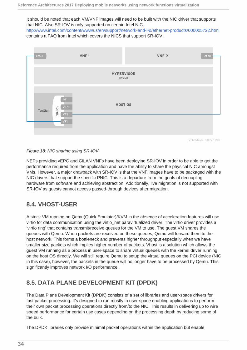
It should be noted that each VM/VNF images will need to be built with the NIC driver that supportsthat NIC. Also SR-IOV is only supported on certain Intel NIC.http://www.intel.com/content/www/us/en/support/network-and-i-o/ethernet-products/000005722.htmlcontains a FAQ from Intel which covers the NICS that support SR-IOV.
Figure 18: NIC sharing using SR-IOV
NEPs providing vEPC and GiLAN VNFs have been deploying SR-IOV in order to be able to get theperformance required from the application and have the ability to share the physical NIC amongstVMs. However, a major drawback with SR-IOV is that the VNF images have to be packaged with theNIC drivers that support the specific PNIC. This is a departure from the goals of decouplinghardware from software and achieving abstraction. Additionally, live migration is not supported withSR-IOV as guests cannot access passed-through devices after migration.
8.4. VHOST-USER
A stock VM running on Qemu(Quick Emulator)/KVM in the absence of acceleration features will usevirtio for data communication using the virtio_net paravirtualized driver. The virtio driver provides a‘virtio ring’ that contains transmit/receive queues for the VM to use. The guest VM shares thequeues with Qemu. When packets are received on these queues, Qemu will forward them to thehost network. This forms a bottleneck and prevents higher throughput especially when we havesmaller size packets which implies higher number of packets. Vhost is a solution which allows theguest VM running as a process in user-space to share virtual queues with the kernel driver runningon the host OS directly. We will still require Qemu to setup the virtual queues on the PCI device (NICin this case), however, the packets in the queue will no longer have to be processed by Qemu. Thissignificantly improves network I/O performance.
8.5. DATA PLANE DEVELOPMENT KIT (DPDK)
The Data Plane Development Kit (DPDK) consists of a set of libraries and user-space drivers forfast packet processing. It’s designed to run mostly in user-space enabling applications to performtheir own packet processing operations directly from/to the NIC. This results in delivering up to wirespeed performance for certain use cases depending on the processing depth by reducing some ofthe bulk.
The DPDK libraries only provide minimal packet operations within the application but enable
Reference Architectures 2017 Deploying mobile networks using network functions virtualization
34
receiving and sending packets with a minimum number of CPU cycles. It does not provide anynetworking stack and instead helps to bypass the kernel network stack in order to deliver highperformance. It is also not intended to be a direct replacement for all the robust packet processingcapabilities (L3 forwarding, IPsec, firewalling, etc.) already found in the kernel network stack (and inmany cases these features aren’t available to DPDK applications.)
In particular, DPDK provides the most significant performance improvement for situations whereyour application needs to handle many small packets (~64 bytes). Traditionally, the Linux networkstack doesn’t handle small packets very well and incurs a lot of processing overhead when dealingwith these small packets thus restricting throughput. The rationale behind the processing overheadis somewhat of a compounded answer. However, it stems from that fact that the Linux network stackis designed to address the needs of general purpose networking applications where commodityhardware is used. It actually works quite well for this use case and not only does it support thevarious protocols across each of the different networks layers, but it can even function as a router.As such, it wasn’t designed (optimized) for cases where you may need to deal with the processingof just these very small packets.
At a high-level technical standpoint, there are several reasons for the bulk including overhead ofallocating/deallocating socket buffers, complexity of the socket buffer (sk_buff) data structure,multiple memory copies, processing of packets layer by layer within the network stack, and contextswitching between kernel level and user-space applications - all of which leads to a CPU bottleneckwhen you have many small packets (resulting in inefficient data processing through the kernel.)
The DPDK libraries are designed to address many of these issues and provide a lightweightframework for getting packets directly to/from applications. The DPDK is broken up into several corecomponents:
Memory Manager
Buffer Manager
Queue Manager
Flow Classification
Poll Mode Drivers
8.5.1. Memory Manager
Responsible for allocating pools of objects in memory
A pool is created in hugepage memory space and uses a ring to store free objects
Also provides an alignment helper to ensure that objects are padded to spread them equally on allDRAM channels
8.5.2. Buffer Manager
Reduces by a significant amount the time the operating system spends allocating and deallocatingbuffers
Pre-allocates fixed size buffers which are stored in memory pools.
8.5.3. Queue Manager
Implements safe lockless (and fixed sized) queue instead of using spin-locks that allow differentsoftware components to process packets while avoiding unnecessary wait times.
CHAPTER 8. PERFORMANCE AND OPTIMIZATION
35
8.5.4. Flow Classification
Provides an efficient mechanism which incorporates Intel Streaming SIMD Extensions (Intel SSE) toproduce a hash based on tuple information so that packets may be placed into flows quickly forprocessing, thus greatly improving throughput
8.5.5. Poll Mode Drivers
Designed to work without asynchronous, interrupt-based signaling mechanisms, which greatlyspeeds up the packet pipeline at the cost of allocating a CPU core to be constantly polling for newpackets.
For vEPC and GiLAN applications that want to use the underlying DPDK-accelerated OVS for highthroughput, it is important to note that to fully take advantage of OVS-DPDK, the guest VMs will alsohave to be DPDK enabled.
8.6. DPDK-ACCELERATED OPEN VSWITCH (OVS-DPDK)
Open vSwitch can be bundled with DPDK for better performance, resulting in a DPDK-acceleratedOVS (OVS+DPDK). At a high level, the idea is to replace the standard OVS kernel datapath with aDPDK-based datapath, creating a user-space vSwitch on the host, which is using DPDK internallyfor its packet forwarding. The nice thing about this architecture is that it is mostly transparent tousers as the basic OVS features as well as the interfaces it exposes (such as OpenFlow, OVSDB,the command line, etc.) remains mostly the same. Figure 19 shows a comparison of standard OVSvs DPDK-accelerated OVS.
The development of OVS+DPDK is now part of the OVS project, and the code is maintainedunder openvswitch.org. The fact that DPDK has established an upstream community of its own waskey for that, so we now have the two communities – OVS and DPDK – talking to each other in theopen, and the codebase for DPDK-accelerated OVS available in the open source community.
Starting with the Red Hat OpenStack Platform 8, DPDK-accelerated Open vSwitch is available forcustomers and partners as a Technology Preview feature based on the work done in upstream OVS2.4. With release of Red Hat OpenStack Platform 10, OVS-DPDK is fully supported. It includes tightintegration with the Compute and Networking layers of OpenStack via enhancements made to theOVS Neutron plug-in and agent. The implementation is also expected to include support fordpdkvhostuser ports (using QEMU vhost-user) so that VMs can still use the standard VirtIOnetworking driver when communicating with OVS on the host.
Red Hat sees the main advantage of OVS+DPDK in the flexibility it offers. SR-IOV, as previouslydescribed, is tightly tied to the physical NIC, resulting in a lack of software abstraction on thehypervisor side. DPDK-accelerated OVS promises to fix that by offering the “best of both worlds”:performance on one hand, and flexibility and programmability through the virtualization layer on theother.
Reference Architectures 2017 Deploying mobile networks using network functions virtualization
36

Figure 19: Standard OVS versus user-space OVS accelerated with DPDK
8.7. DPDK WITH RED HAT OPENSTACK PLATFORM
Generally, we see two main use-cases for using DPDK with Red Hat and Red Hat OpenStackPlatform.
1. DPDK enabled applications, or VNFs, written on top of Red Hat Enterprise Linux as a guestoperating system. Here we are talking about Network Functions that are taking advantageof DPDK as opposed to the standard kernel networking stack for enhanced performance.
2. DPDK-accelerated Open vSwitch, running within Red Hat OpenStack Platform computenodes (the hypervisors). Here it is all about boosting the performance of OVS and allowingfor faster connectivity between VNFs.
We would like to highlight that if you want to run DPDK-accelerated OVS in the compute node, youdo not necessarily have to run DPDK-enabled applications in the VNFs that plug into it. This can beseen as another layer of optimization, but these are two different fundamental use-cases.
CHAPTER 8. PERFORMANCE AND OPTIMIZATION
37
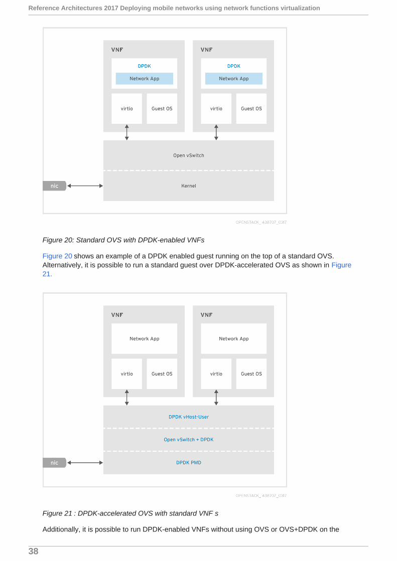
Figure 20: Standard OVS with DPDK-enabled VNFs
Figure 20 shows an example of a DPDK enabled guest running on the top of a standard OVS.Alternatively, it is possible to run a standard guest over DPDK-accelerated OVS as shown in Figure21.
Figure 21 : DPDK-accelerated OVS with standard VNF s
Additionally, it is possible to run DPDK-enabled VNFs without using OVS or OVS+DPDK on the
Reference Architectures 2017 Deploying mobile networks using network functions virtualization
38

Compute node, and utilize SR-IOV instead. This configuration requires a VF Poll Mode Driver(PMD) within the VM itself as shown in Figure 22.
Figure 22: SR-IOV with DPDK enabled VNFs
As we have mentioned earlier, the vEPC and GiLAN VNF requires very high throughput as itterminates millions of subscribers. As such, it is recommended the NEPs use the DPDK-acceleratedOVS with DPDK enabled VNFs as shown in Figure 23. This option will provide the best throughputwhile still offering decoupling from specific NIC hardware.
CHAPTER 8. PERFORMANCE AND OPTIMIZATION
39

Figure 23: DPDK-accelerated OVS with DPDK enabled VNFs
To improve the performance of OVS with DPDK, vHost user multiqueue support was introduced.
vHost user as explained earlier improved overall throughput by allowing the VM that runs in userspace to bypass the QEMU and directly talk to the kernel memory using sockets. This standardvHost user setup looks like what is shown in Figure 24.
Reference Architectures 2017 Deploying mobile networks using network functions virtualization
40

Figure 24: vHost single queue
This single queue on the guest VM can become a bottleneck. To overcome this problem and tofurther speedup packet transfer, vHost multiqueue can be employed. This is illustrated in Figure 25.More details on multiqueue vHost user is available at: https://software.intel.com/en-us/articles/configure-vhost-user-multiqueue-for-ovs-with-dpdk
CHAPTER 8. PERFORMANCE AND OPTIMIZATION
41
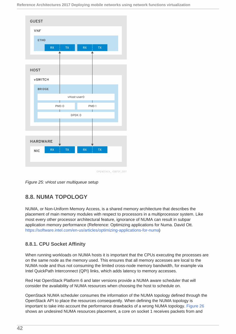
Figure 25: vHost user multiqueue setup
8.8. NUMA TOPOLOGY
NUMA, or Non-Uniform Memory Access, is a shared memory architecture that describes theplacement of main memory modules with respect to processors in a multiprocessor system. Likemost every other processor architectural feature, ignorance of NUMA can result in subparapplication memory performance (Reference: Optimizing applications for Numa. David Ott.https://software.intel.com/en-us/articles/optimizing-applications-for-numa)
8.8.1. CPU Socket Affinity
When running workloads on NUMA hosts it is important that the CPUs executing the processes areon the same node as the memory used. This ensures that all memory accesses are local to theNUMA node and thus not consuming the limited cross-node memory bandwidth, for example viaIntel QuickPath Interconnect (QPI) links, which adds latency to memory accesses.
Red Hat OpenStack Platform 6 and later versions provide a NUMA aware scheduler that willconsider the availability of NUMA resources when choosing the host to schedule on.
OpenStack NUMA scheduler consumes the information of the NUMA topology defined through theOpenStack API to place the resources consequently. When defining the NUMA topology isimportant to take into account the performance drawbacks of a wrong NUMA topology. Figure 26shows an undesired NUMA resources placement, a core on socket 1 receives packets from and
Reference Architectures 2017 Deploying mobile networks using network functions virtualization
42

transmits packets to interfaces on socket 0. This is the worst case situation. (Reference: NetworkFunction Virtualization: Virtualized BRAS with Linux* and Intel® Architecturehttps://networkbuilders.intel.com/docs/Network_Builders_RA_vBRAS_Final.pdf)
Figure 26: NUMA node Sub-optimal I/O scenarios
To avoid the previous situation, it’s recommended to select a NUMA topology of 1 numa node, sothat the OpenStack Compute scheduler will deploy the resulting scenario shown in Figure 27.
Figure 27: NUMA node optimal I/O scenarios
The drawback of doing this is the VM might not fit into one NUMA node depending on the resourcesavailable and used on the hosts.
For virtual mobile as well as for all other NFV applications, it is also important that the I/O devices(NICs) conform to NUMA topology. Because NFV applications are network intensive, if the NICs arenot collocated with the CPUs there is a significant performance hit (up to 30%)!
8.9. HUGE PAGES
CHAPTER 8. PERFORMANCE AND OPTIMIZATION
43

From a memory management perspective, the entire physical memory is divided into "frames" andthe virtual memory is divided into "pages".
The memory management unit performs a translation of virtual memory address to physical memoryaddress. The information regarding which virtual memory page maps to which physical frame is keptin a data structure called the "Page Table". Page table lookups are costly. In order to avoidperformance hits due to this lookup, a fast lookup cache called Translation Lookaside Buffer (TLB) ismaintained by most architectures. This lookup cache contains the virtual memory address tophysical memory address mapping. So any virtual memory address which requires translation to thephysical memory address is first compared with the translation lookaside buffer for a valid mapping.
When a valid address translation is not present in the TLB, it is called a "TLB miss". If a TLB missoccurs, the memory management unit will have to refer to the page tables to get the translation. Thisbrings additional performance costs, hence it is important that we try to reduce the TLB misses.
Most modern virtualization hosts support a variety of memory page sizes. On x86 the smallest, usedby the kernel by default, is 4kb, while large sizes include 2MB and 1GB. The CPU TLB cache has alimited size, so when there is a very large amount of RAM present and utilized, the cache efficiencycan be fairly low which in turn increases memory access latency. By using larger page sizes, thereare fewer entries needed in the TLB and thus its efficiency goes up. [3]
The ability to control the amount of page memory in kilobytes (KB) exposed to the guest has beenavailable since Red Hat OpenStack Platform 6.
8.10. CPU CONSUMPTION
Dedicated EPC hardware may have dedicated processors to perform network I/O. In someimplementations, NEPs use specialized ASICs (Application-Specific Integrated Circuits) to speedupnetwork I/O. For vEPC/GiLAN and NFV in general (except for cases where we use OVS offload andother hardware assist techniques), network I/O is performed by CPU of the server. Typically, when apacket arrives on the input queue the CPU gets an interrupt and one of the cores is assigned tomove the packet from the input queue to the VM. Simply put, network I/O consumes CPU. Becauseof this reason, it is important to dimension the servers with adequate horsepower to not performclassic processor bound tasks but also for network I/O operations.
vEPC vendors (true for other VNFs as well) provide guidelines for running each VNF andapplication (MME, SGW/PGW, ePDG). They usually recommend the number virtual CPUs (vCPUs)required for that application along with the DRAM and disk.
Physical CPU model is a moving target. Newer, better and faster CPUs are released by Intel andother vendors constantly. For validating this architecture the following specifications were used forserver hardware:
2 Intel Xeon Processor E5-2650v4 12-Core
128GB of DRAM
Intel x540 10G NIC cards
Storage:
400GB SSD drives for Ceph monitors
300GB SAS drives for the host OS
6TB SAS drives for Ceph OSD
Reference Architectures 2017 Deploying mobile networks using network functions virtualization
44

It should be noted that even with dataplane acceleration such as OVS with DPDK, in order to getadequate throughput, multiple CPUs may need to be assigned depending on the requirementfollowing NUMA guidelines.
8.11. CPU PINNING
CPU pinning is a technique that allows processes/threads to have an affinity configured with one ormultiple cores.
By configuring a CPU affinity, the scheduler is now restricted to only scheduling the thread toexecute on one of the nominated cores. In a NUMA configuration, if specific NUMA memory isrequested for a thread, this CPU affinity setting will help to ensure that the memory remains local tothe thread. Figure 28 shows a logical view of how threads that can be pinned to specific CPU coresand memory can be allocated local to those cores. Details of this can be found in A Path to Line-
Rate-Capable NFV Deployments with Intel® Architecture and the OpenStack® Juno Release
https://networkbuilders.intel.com/docs/PathToLine-Rate_WP_V1.pdf
Figure 28: Pinning threads to CPU cores.
CHAPTER 8. PERFORMANCE AND OPTIMIZATION
45

CHAPTER 9. TRAFFIC PROFILE AND DIMENSIONING
vEPC and for that matter hardware based EPC solutions are typically based on use-case, call-model(ePDG, PGW, SGW/PGW or MME/SGW), number of subscribers being served. Typically, mobileoperators share “call model” (exact call flow ladder diagrams) with NEPs so that the vEPC setupand configuration is tailored for that application.
vEPC consist of a rich set of features and capabilities ranging from normal 3gpp functions (SGW,PGW, MME etc) to Deep Packet Inspection (DPI), URL filtering/enrichment, Video/Content cachingetc. Additionally for a connected-cars use case the same 3gpp functions may have different scalingrequirements than when terminating 10 Million subscribers with smartphones. Good news is mostvEPC VNFs are expected to support all these services and applications. They can be viewed asSwiss Army Knives as shown in Figure 29.
Figure 29: vEPC applications and their relationship to system resources
Based on the application, the dimensioning of vEPC could vary. IoT/M2M (Machine to Machine) istypically high in session count but low from throughput requirement. IoT devices could vary fromsmall devices embedded in fields measuring nitrogen and moisture content to health care industrywhere it may be used to measure and ensure consistent temperature of medicine or organs beingtransported. These devices are typically not very chatty. They wake up, say what they need to sayusing tiny messages (could even be SMS) and then they go back to sleep. Due to the very highsession count (imagine a future world where every device and appliance has an IPv6 address and iscapable of communicating), the vEPC would have to be dimensioned for high memory. Billingapplications take Call Data Records (CDRs) and creating and store billing entry constantly on disk.For this vEPC and underlying infrastructure (OpenStack and Hardware) will need to be designed andprovisioned so that this constant Input/Output Operations (IOPs) don’t become an issue. Policy andcontrol applications (PCRF) and Radius could be very chatty. Constant messaging occurs based onvarious activity of the subscribers. VoLTE (Voice over Long Term Evolution) is the voice applicationfor 4G/LTE mobile networks. Voice typically implies a lot of small packets (We spec for 64 bytepackets, however, in reality they could be more like 100 bytes and vary based on codec beingused). In summary, there has to be some design and tuning done at the infrastructure level toaccommodate different mobile services running on top of vEPC.
Table 2 summarizes the general requirements of vEPC. Some deployments could be smaller whileothers larger. While some KPIs such as session count, total bandwidth requirement could varybased on size of the deployment, others stay constant. Important KPIs to pay attention to are packetloss, jitter and latency.
Reference Architectures 2017 Deploying mobile networks using network functions virtualization
46

Table 2: vEPC Traffic Profile (Source: OPNFV Summit 2016)
Dimensioning for GiLAN and IMS tracks that of vEPC or EPC subscribers if GiLAN is deployed witha non-virtualized EPC.
CHAPTER 9. TRAFFIC PROFILE AND DIMENSIONING
47
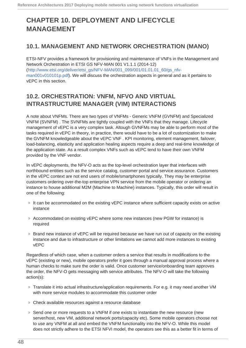
CHAPTER 10. DEPLOYMENT AND LIFECYCLEMANAGEMENT
10.1. MANAGEMENT AND NETWORK ORCHESTRATION (MANO)
ETSI-NFV provides a framework for provisioning and maintenance of VNFs in the Management andNetwork Orchestration in ETSI GS NFV-MAN 001 V1.1.1 (2014-12)(http://www.etsi.org/deliver/etsi_gs/NFV-MAN/001_099/001/01.01.01_60/gs_nfv-man001v010101p.pdf). We will discuss the orchestration aspects in general and as it pertains tovEPC in this section.
10.2. ORCHESTRATION: VNFM, NFVO AND VIRTUALINTRASTRUCTURE MANAGER (VIM) INTERACTIONS
A note about VNFMs. There are two types of VNFMs - Generic VNFM (GVNFM) and SpecializedVNFM (SVNFM) . The SVNFMs are tightly coupled with the VNFs that they manage. Lifecyclemanagement of vEPC is a very complex task. Altough GVNFMs may be able to perform most of thetasks required in vEPC in theory, in practice, there would have to be a lot of customization to makethe GVNFM knowledgeable about the vEPC VNF . KPI monitoring, element management, failover,load-balancing, elasticity and application healing aspects require a deep and real-time knowledge ofthe application state. As a result complex VNFs such as vEPC tend to have their own VNFMprovided by the VNF vendor.
In vEPC deployments, the NFV-O acts as the top-level orchestration layer that interfaces withnorthbound entities such as the service catalog, customer portal and service assurance. Customersin the vEPC context are not end users of mobile/smartphones typically. They may be enterprisecustomers ordering over-the-top enterprise VPN service from the mobile operator or ordering aninstance to house additional M2M (Machine to Machine) instances. Typically, this order will result inone of the following:
It can be accommodated on the existing vEPC instance where sufficient capacity exists on activeinstance
Accommodated on existing vEPC where some new instances (new PGW for instance) isrequired
Brand new instance of vEPC will be required because we have run out of capacity on the existinginstance and due to infrastructure or other limitations we cannot add more instances to existingvEPC
Regardless of which case, when a customer orders a service that results in modifications to thevEPC (existing or new), mobile operators prefer it goes through a manual approval process where ahuman checks to make sure the order is valid. Once customer service/onboarding team approvesthe order, the NFV-O gets messaging with service attributes. The NFV-O will take the followingaction(s):
Translate it into actual infrastructure/application requirements. For e.g. it may need another VMwith more service modules to accommodate this customer order
Check available resources against a resource database
Send one or more requests to a VNFM if one exists to instantiate the new resource (newserver/host, new VM, additional network ports/capacity etc). Some mobile operators choose notto use any VNFM at all and embed the VNFM functionality into the NFV-O. While this modeldoes not strictly adhere to the ETSI NFVI model, the operators see this as a better fit in terms of
Reference Architectures 2017 Deploying mobile networks using network functions virtualization
48
architectural alignment as well as operational. It should be noted that the NFV-O in actualdeployments may also talk to some configuration automation engine such as Red Hat Ansible topush configurations to underlay network elements or other lower layer requests that will berequired to complete this order.
The next step is for the VNFM to translate the request from the NFV-O into actual commandsthat the VIM would understand. For e.g. it may be a “Nova Boot” or “Neutron Net Create” etc.
Success or failure is reported back to NFV-O.
NFV-O updates resource database if required, updates order processing system, adds the newresources into the service assurance system or fault management system to monitor
Figure 30 shows a flow diagram with details of VNF instantiation as recommended by ETSI. Itshould be noted that vEPC VNFs may be accompanied by Element Managers (EMs) that assist inmanaging the VNF from an application standpoint.
Figure 30: VNF Instantiation flow as per ETSI
10.3. DAY0 CONFIG
CHAPTER 10. DEPLOYMENT AND LIFECYCLE MANAGEMENT
49

The VNFM typically is responsible for Day0 configuration. It will start the VM using the ssh-keysassigned for it, configure Eth0 if required for management/SSH access. All higher levelconfiguration such as protocols (BGP, Firewall rules etc.) will be done through configurationautomation tool such as Ansible.
10.4. FIXED IP ADDRESSING
For internal communication between the control modules and service modules, vEPC applicationmay have reserved internal IP address ranges. These are typically RFC-1918 non-routable IPsubnets. The application may choose not to use the DHCP services offered by OpenStack L3 agent.
If the platform uses provider networks for their tenant connectivity and compute hosts don’t haveaccess to the dhcp-agent running on the controller using the provider networks, special provisionsneed to be made to enable DHCP services for the guests, or the guests need to use pre-provisionedstatic IP addresses. One of the ways to accomplish this is to use config-drive to pass networkinginformation to the guests. Images used to instantiate the VMs need to contain a cloud-init packagecapable of mounting the config-drive or a special script can be created to mount the drive,depending on the guest OS.
10.5. VIRTUALIZED INFRASTRUCTURE MANAGER (VIM)
While mobile VNF vendors tend to support both OpenStack as well as VMWare, the focus of thisdocument will be around Red Hat OpenStack Platform as a VIM. vEPC VNFMs may use somemiddleware to abstract the VIM API requests (for e.g. OpenStack API).
Reference Architectures 2017 Deploying mobile networks using network functions virtualization
50
CHAPTER 11. SECURITY
Security is top-of-mind for Telcos and specifically mobile operators. Security violations lead todowntime which goes against the high availability requirements of Telcos. There are stringentsecurity requirements that is stipulated by most local governments where EPC (3G or 4G) isdeployed. Any network or cloud deployment needs to be protected from malicious attacks. The keydifference is that in the past we used proprietary hardware and even protocols which were harder tohack.
In context of vEPC “Lawful/Legal Intercept” (LI) comes to mind. Many governments require serviceproviders/operators to be able to identify the subscriber based on request and furthermore, “Camp-on” that subscriber’s session to be able to track messaging or data that is being transmitted on thatsession. The government could also request triangulation of the subscriber to obtain the location ofthe subscriber in certain cases. In the past EPC/MPC (Mobile Packet Core - 3G) ran on dedicatedhardware where sensitive information about subscribers were mostly passed between blades ofchassis in most instances. The LI packets would be traversing the backplane of the EPC/MPChardware and not in any danger of being exposed to hackers. With the advent of virtualization andcloud, the VMs that constitute the vEPC VNFs could span several servers spread across the cloud.vEPC typically would be deployed on private cloud opposed to public cloud such as AmazonWedbServices(AWS) and Microsoft Azure. However, MVNOs could obtain access to certain applications“as a Service” which could bring public cloud into context. The LI packets that traverse the cloudwould now have to be encrypted due to their sensitive nature. This may have significant impact onpacket throughput unless specific steps are taken to use dedicated hardware with sufficienthorsepower to perform the encryption/decryption and in some cases even use hardware assist.
Mobile operators go through numerous measures to ensure the environment in which vEPC runs issecure. This includes but not limited to:
Using rack-mount servers instead of blade servers . This is done by some operators as theyrequire console access to the physical servers. Blade servers use virtual consoles. If and when aVM is compromised if all else fails, the operator may chose to use this Out Of Band (OOB)access the server and shut it down
Create zoning . The operators may employ zoning to segregate portions of the datacenter(servers) that house and deal with sensitive information such as subscriber database, policyservers etc into a “Secure Zone”. Only control plane data typically requires access to the securezone. Data plane is separated into its own zone. Firewalls are employed between zones tominimize exposure to security threats and hacking.
Hardening hardware and software : Service providers/Mobile operators require NEPs toprovide hardware and software that is hardened and less susceptible to security threats.Additionally installing software updates and patches on a regular interval and conducting securityaudits is required.
Platform Hardening (Hardware, Host OS and OpenStack) is not new to service providers. Mobileoperators should apply the same procedures and ensure security best practices are applied up anddown the stack from application all the way to the hardware, layer by layer.
11.1. OPERATIONAL BEST PRACTICES
Security cannot be an afterthought. It is very hard to go back to a completely open environment andplug holes. It needs to be thought through along with the architecture and design of a network. Thisrequires security operational procedures to be agreed upon, documented, maintained andimplemented. This includes but not limited to:
CHAPTER 11. SECURITY
51
Physical security: Who has physical access to the datacenter. Even within the datacenter, it isimportant to partition racks that belong to groups and create barriers or cages that only thosegroups have access to. Sometimes the racks may be in Co-Los (Colocated in shared datacenteralso known as “hoteling”)
Limiting access: Many Telcos will allow changes to be made to servers and network equipmentto a very small set of individuals. Others will to open a ticket to get this done. Often theservers/switches can only be accessed is through jump-servers or known hosts. Additionally,there are several levels of privileges that are assigned and controlled using AAA/Radius servers.Just because someone can logon to a server/switch they cannot make configuration changes orcause damage
Audit Trails: All access to servers/switches should be logged with accurate timestamps anddetails of individuals who execute commands and what commands were executed.
Credentials: Most Telcos implement complex passwords and require these password bechanged periodically. In some cases the passwords are assigned by the Telco to theusers/admins and cannot be modified.
Monitoring: Syslogs, SNMP traps and log messages have to be proactively monitored forsecurity violations such as repeated password failure or someone trying to access somethingthat they are are not authorized to.
11.2. HARDWARE AND SOFTWARE
Hardware: Server and switch firmware, BIOS etc have to be known certified quantities.Additionally NIC level settings such as which port is allowed to PXE boot etc should becontrolled. There are some things to be aware of with hardware:
PCI passthrough uses DMA to speed up transfers and allows access to physical memory onthe host. If compromised due by using a rogue firmware, it can potentially cause damage.
Infected hardware is hard to manage, reset etc and may result in running the virtualmachines in an unsecure environment.
Host OS and Virtualization: The hypervisor can become a weak link. If it has vulnerabilities,attacks can be launched starting from the guest VM, breaking out using this vulnerability in thehypervisor, replicating itself. If it reaches the host, it can access other tenants as well. It isimportant to proactively harden QEMU and KVM by maintaining uniform code base, usingcompiler hardening, and access control using SELinux. We should keep in mind that while thebeauty of NFV is to mix and match VNF vendors it can also become a security bottleneck as notall vendors would have gone through the same high level of hardening and taken precautions asothers. Many hypervisor vendors including Red Hat have achieved Common Criteria Certification- Identification and Authentication, Audit, Role-Based Access Control etc. Details of this topic canbe obtained at http://docs.openstack.org/sec/
Cryptography: Several options are available within OpenStack to use cryptography for variousactivities such as identification and authorization, data transfer and protection of data at rest.
ETSI provides detailed guidelines on security and platform hardening for NFV. This can be found in“ETSI GS NFV-SEC 012 V0.0.13 (2016-11)” and related documents.
The OpenStack security project issues Security Advisories (OSSA) and Security Notes (OSSN)which operators, infrastructure providers as well as NEPs who provide VNFs should pay attentionto.
Reference Architectures 2017 Deploying mobile networks using network functions virtualization
52
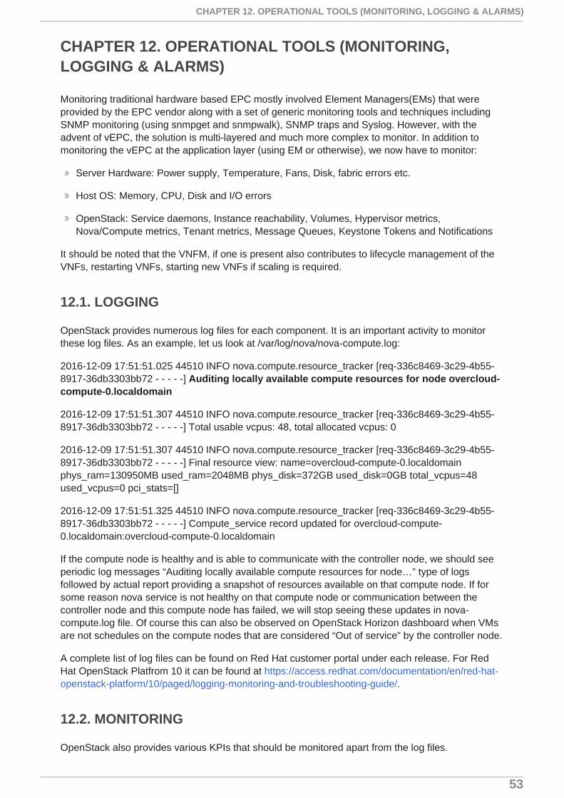
CHAPTER 12. OPERATIONAL TOOLS (MONITORING,LOGGING & ALARMS)
Monitoring traditional hardware based EPC mostly involved Element Managers(EMs) that wereprovided by the EPC vendor along with a set of generic monitoring tools and techniques includingSNMP monitoring (using snmpget and snmpwalk), SNMP traps and Syslog. However, with theadvent of vEPC, the solution is multi-layered and much more complex to monitor. In addition tomonitoring the vEPC at the application layer (using EM or otherwise), we now have to monitor:
Server Hardware: Power supply, Temperature, Fans, Disk, fabric errors etc.
Host OS: Memory, CPU, Disk and I/O errors
OpenStack: Service daemons, Instance reachability, Volumes, Hypervisor metrics,Nova/Compute metrics, Tenant metrics, Message Queues, Keystone Tokens and Notifications
It should be noted that the VNFM, if one is present also contributes to lifecycle management of theVNFs, restarting VNFs, starting new VNFs if scaling is required.
12.1. LOGGING
OpenStack provides numerous log files for each component. It is an important activity to monitorthese log files. As an example, let us look at /var/log/nova/nova-compute.log:
2016-12-09 17:51:51.025 44510 INFO nova.compute.resource_tracker [req-336c8469-3c29-4b55-8917-36db3303bb72 - - - - -] Auditing locally available compute resources for node overcloud-compute-0.localdomain
2016-12-09 17:51:51.307 44510 INFO nova.compute.resource_tracker [req-336c8469-3c29-4b55-8917-36db3303bb72 - - - - -] Total usable vcpus: 48, total allocated vcpus: 0
2016-12-09 17:51:51.307 44510 INFO nova.compute.resource_tracker [req-336c8469-3c29-4b55-8917-36db3303bb72 - - - - -] Final resource view: name=overcloud-compute-0.localdomainphys_ram=130950MB used_ram=2048MB phys_disk=372GB used_disk=0GB total_vcpus=48used_vcpus=0 pci_stats=[]
2016-12-09 17:51:51.325 44510 INFO nova.compute.resource_tracker [req-336c8469-3c29-4b55-8917-36db3303bb72 - - - - -] Compute_service record updated for overcloud-compute-0.localdomain:overcloud-compute-0.localdomain
If the compute node is healthy and is able to communicate with the controller node, we should seeperiodic log messages “Auditing locally available compute resources for node…” type of logsfollowed by actual report providing a snapshot of resources available on that compute node. If forsome reason nova service is not healthy on that compute node or communication between thecontroller node and this compute node has failed, we will stop seeing these updates in nova-compute.log file. Of course this can also be observed on OpenStack Horizon dashboard when VMsare not schedules on the compute nodes that are considered “Out of service” by the controller node.
A complete list of log files can be found on Red Hat customer portal under each release. For RedHat OpenStack Platfrom 10 it can be found at https://access.redhat.com/documentation/en/red-hat-openstack-platform/10/paged/logging-monitoring-and-troubleshooting-guide/.
12.2. MONITORING
OpenStack also provides various KPIs that should be monitored apart from the log files.
CHAPTER 12. OPERATIONAL TOOLS (MONITORING, LOGGING & ALARMS)
53
With OpenStack, monitoring the metrics and events listed in the table below enables mobileoperators with insights into the performance, availability and overall health of OpenStack.
Most useful metrics the following:
hypervisor_load
running_vms
free_disk_gb
free_ram_mb
queue memory
queue consumers
consumer_utilisation
Details and a more complete listing of OpenStack KPIs can be found athttps://www.datadoghq.com/blog/openstack-monitoring-nova/?ref=wikipedia.
Reference Architectures 2017 Deploying mobile networks using network functions virtualization
54
CHAPTER 13. CONCLUSION
Mobile operators have moved from proof-of-concepts (PoCs) to trials to production using virtualizedmobile network elements. This was first pioneered by Tier1 operators and we are seeing it beingfollowed by Tier2 and Tier3 operators around the world. Virtual mobile network offer the operatorsfreedom from vendor lock-in, ability to grow and shrink the network based on demand without havingto order and deploy new hardware. This has been made easy to deploy due to the Orchestration andManagement functions. Further operational gains can be gained by leveraging configurationautomation tools such as Ansible by Red Hat. NEPs and Telcos are working against the backdropset by ETSI NFV standards body in standardizing the way NFV can be implemented, deployed andmanaged.
CHAPTER 13. CONCLUSION
55

APPENDIX A. CONTRIBUTORS
We would like to thank the following individuals for their time and patience as we collaborated onthis process. This document would not have been possible without their many contributions.
Contributor Title Contribution
Marcos Garcia Techincal ProductMarketing Manager
SME NFV
Nir Yechiel Sr Product Mgr SME Neutron Networking
Rimma Iontel Senior Arhcitect SME Telco/NFV & Review
Rashid Khan Manager SoftwareEngineer
SME Networking
Aaron Smith Sr. Prinicipal SoftwareEng
SME Telco, NFV & HA, Design, Testing & Review
David Critch Partner Systems Eng SME OpenStack, Review
Azhar Sayeed Chief TechnologistTelco
Subject Matter Review
Andrew Bays Senior SoftwareEngineer
SME HA, Deployment, Testing & Review
Jess Schaefer Graphic Designer Diagrams
Emma Eble Multimedia Designer Diagrams
Reference Architectures 2017 Deploying mobile networks using network functions virtualization
56

APPENDIX B. REVISION HISTORY
Revision 1.4-0 2017-06-15 AS
APPENDIX B. REVISION HISTORY
57