reducing wrinkling and tearing of deep draw …umpir.ump.edu.my/3450/1/cd6251_61.pdf · reducing...
TRANSCRIPT
i
REDUCING WRINKLING AND TEARING OF DEEP DRAW PART
MOHD NAEEMIL MAHMUDI BIN MAHMUD
A report submitted in fulfilment of the requirements
for the award of the degree of
Bachelor of Manufacturing Engineering
Faculty of Manufacturing Engineering
UNIVERSITI MALAYSIA PAHANG
MAY 2012
vii
ABSTRACT
Some of the most common outcomes in deep drawing process are tearing and wrinkling or the formation of uneven height at the top rim of a drawn part due to the material anisotropy. This project involves experimental and numerical studies of the die design to investigate the formability of sheet metal. The main objective of this project is to obtain the best deep drawing parameters in reducing wrinkle and tearing during a cylindrical cup deep draw process. The project begins with the die design using Computer Aided Design (CAD) software. The project is continued with modelling of finite element model (FEM) using simulation software. The variables for this project are die clearance, die radius, and blank holding force. The constant of this simulation are thickness of sheet metal and punch size to deform the material. All the data from finite element software showed the different value of displacement. From the data documentation, the discussion and result were concluded to determine the effect of different parameters on wrinkling and tearing phenomenon during sheet metal forming process.

viii
TABLE OF CONTENT
Page
EXAMINERS’ APPROVAL DOCUMENT ii
SUPERVISOR’S DECLARATION iii
STUDENT’S DECLARATION iv
DEDICATION v
ACKNOWLEDGEMENT vi
ABSTRACT vii
TABLE OF CONTENTS viii
LIST OF FIGURES xi
LIST OF TABLES xiii
LIST OF SYMBOLS xiv
LIST OF ABBREVIATIONS xv
CHAPTER 1 INTRODUCTION
1.1 Project synopsis 1
1.2 Background of study 1
1.3 Problem statement 3
1.4 Objectives 4
1.5 Scope of study 4
1.6 Project specification 4
1.7 Project flow chart 5
CHAPTER 2 LITERATURE REVIEW
2.1 Basic characteristic of sheet metal forming process 6
2.2 Material selection for die fabrication 6
2.2.1 Type of tool steel 7
2.3 Mechanics of deep drawing
2.3.1 Die concept 7

ix
2.3.2 Draw stages 82.3.3 Die clearance and radius 92.3.4 Blank size 122.3.5 Limit draw ratio 142.3.6 Drawing force 152.3.7 Blank holder force 16
2.4 Finite element method 18
2.4.1 Advantage of finite element method 19
CHAPTER 3 METHODOLOGY
3.1 Introduction 20
3.2 Flow chart 20
3.3 Die design 22
3.4 Finite element modelling 23
3.5 Bill of material 24
3.6 Fabrication process
3.6.1 CNC milling machine 253.6.2 CNC lathe machine 26
3.7 Die assembly 27
3.8 Testing and troubleshoot 27
CHAPTER 4 RESULTS AND DISCUSSION
4.1 Finite element simulation
4.1.1 Simulations for 20mm Cup Without Flange 294.1.2 Simulations for 20mm Cup With Flange 324.1.3 Simulations for 25mm Cup With Flange 34
4.2 Experimental result 36
4.3 Conclusion 41

x
CHAPTER 5 CONCLUSIONS
5.1 Conclusion 42
5.2 Recommendation 43
REFERENCES 44
APPENDICES
A Technical drawing for cylindrical cup

xi
LIST OF FIGURES
Figure No. Title Page
1.1 Wrinkling & tearing in deep drawing 2
1.2 Project flow chart 5
2.1 Cylindrical cup 9
2.2 Punch & die clearance 11
2.3 Draw element 12
2.4 Draw area ` 12
2.5 Cylindrical cup 12
2.6 Blank holder formula 17
2.7 Blank reduction percentage 17
3.1 Process planning flow chart 21
3.2 Complete die design 22
3.3 General work flow diagram 23
3.4 Milling process 25
3.5 Punch with 5mm corner radius 26
3.6 Taping process 27
3.7 Assembly process 27
3.8 Stamping machine 28
3.9 Pre stamping process 28
3.10 Die shut height 28
4.1 Blank development for cup without flange 29
4.2 Formability result for cup without flange 30
4.3 Thinning result for cup without flange 31

xii
4.4 20mm draw height blank development 32
4.5 20mm draw height formability result 33
4.6 20mm draw height thinning result 33
4.7 25mm draw height formability result 34
4.8 25mm draw height thinning result 35
4.9 20mm draw height of steel plate 36
4.10 20mm draw height of copper plate 36
4.11 Parts cut into pieces 37
4.12 Micrometer 37
4.13 Maximum thinning area for 0.9 tonne BHF 38
4.14 Maximum thinning area for 1.2 tonne BHF 39
4.15 Maximum wrinkling area for 0.9 tonne BHF 40
4.16 Maximum wrinkling area for 1.2 tonne BHF 40

xiii
LIST OF TABLES
Table No. Title Page
1.1 Gantt chart 6
2.1 Number of draws (n) for a cylindrical cup 9
2.2 Absolute value for clearance 10
2.3 Mean value for β 14
2.4 Correction value, n 15
3.1 Bill of material 24
4.1 Maximum value of thinning for 20mm draw height 38
4.2 Maximum value of wrinkle for 20mm draw height 39

xiv
LIST OF SYMBOLS
A = area to be cut
L = length of material
T = Thickness of material
D = diameter of blank
W = width of rectangle
C = Clearance ( per side )
Ø = Diameter
d = Depth of draw

xv
LIST OF ABBREVIATIONS
JIS Japaneese Industrial Standards
HB Hardness Brinell
CAD Computer aided design
mm millimeters
CNC Computer Numerical Control
rpm Revolution per minute
2D Two dimensional
3D Three dimensional
FEA Finite Element Analysis
FEM Finite Element Model

1
CHAPTER 1
INTRODUCTION
1.1 PROJECT SYNOPSIS
In sheet metal forming, a blank sheet is subjected to plastic deformation using
forming tools to achieve the designed shape. During this process, the blank sheet will
develop defects if the process parameters are not selected properly. Failure of sheet
metal parts during deep drawing processes usually takes place in the form of wrinkling
or tearing. Therefore, it is important to optimize the process parameters to avoid defects
in the parts and to minimize production cost. Many variables affect the failure, these
includes material properties, the punch and die clearance, the punch and die radius, the
blank holding force, the die cavity depth, and the cushion pressure. This experimental
project is to overcome the wrinkling and tearing of the deep drawn parts. In this project,
an 80 tonnage stamping machine and sheet metals of 1mm thickness are used to
produce cylindrical cup shape product with 50mm diameter and 20mm length.
1.2 BACKGROUND OF STUDY
Deep draw stamping is a process that’s been widely uses in the manufacturing
field especially in the oil and gas industry, the automotive industry, and also used to
produces a range of household items such as soup cans, battery casings, fire
extinguishers, and even a kitchen sink. A part is called deep drawn if the depth of the
part is at least half of its diameter. Otherwise, it is simply called general stamping. A
deep drawn part may have one or more drawing operations depending on the
complexity of the part. In a deep drawing process, a punch pushes a sheet metal blank

2
into a die cavity, resulting the desired contoured part. Multi stage drawing process of a
blank material experiences additional complex deformation in each stage compared to a
conventional drawing process. The process generally involves additional bending,
stretching, compression and shearing by different drawing ratios during the subsequent
drawing stage. The deformation naturally proceeds with the irregular shapes of the cross
section and conditions that cause failure such as tearing and wrinkling. Since the
deformation mechanism is very complicated and the final mechanical properties are
difficult to predict, the process design is not an easy task for the manufacture of a
product of desired shape and material properties.
The success or failure of the forming process is influenced by many process
parameters such as the drawing ratio in each stage, the difference of the drawing ratio
within the cross-section, the shape of the die, the strain-hardening coefficient, material
formability, the lubrication conditions and the degree of ironing. One of the key
parameters affecting the forming process is the blank holder force (BHF). The
advantage of varying the blank holder force during the forming process is the two
primary model of failure which are wrinkling and tearing (Fig. 1.1) are avoided. This
gives rise to improved formability, higher accuracy and better part consistency.
Figure 1.1: Wrinkling & tearing in deep drawing
Source: Huh H. and Kim S. 2001
TEARING
WRINKLE

3
1.3 PROBLEM STATEMENT
Wrinkling of sheet metal material in deep drawing operations generally occur in
the wall or flange of the part. During the process, a blank between a die and a punch is
held by means of a blank holding force (BHF). The flange of the blank undergoes radial
drawing stress and tangential compressive stress during the stamping process that
causes the sheet to buckle locally. The radial tensile stress is due to the blank being
pulled into the female die, and the compressive stress, normal in the blank sheet is due
to the blank holder force (BHF). The difference in the drawing ratio and the irregular
contact condition between the blank and die which occur when using second and third
method of redrawing, also induces non uniform metal flow which cause wrinkling,
tearing, and severe extension of metal during the redrawing process. On the other hand,
fracture or necking occurs in a drawn part which is under excessive tensile stresses.
Wrinkling and tearing rupture thus define the deep drawing process limits (Pepelnjak
and K. Kuzman, 2007).
Wrinkling and tearing are preventable if the deep drawing system and stamped
part are designed properly in term of die radius, die clearance and blank holding
force (BHF). It is important to adjust the blank holder force exerted on the edges of the
blank so that it is not just sufficiently great to prevent wrinkle formation at the edges but
at the same time not greater than what is necessary as this promotes tearing and
furthermore leads to high frictional forces between the blank, the blank holder and the
die itself. Such undesired forces cost unnecessarily much energy during deep drawing
process which leads to wear and shorten the life of the punch and die.

4
1.4 OBJECTIVES
1. To design a deep drawing die for cylindrical cup drawing operation.
2. To investigate the effects of draw depth and blank holder force in deep
drawing process.
3. To obtain the best deep drawing parameter in reducing wrinkle and tearing
during deep draw process.
1.5 SCOPE OF STUDY
Cylindrical cups’ drawing is responsible for the manufacture of billions of metal
containers. Therefore, in this project a cylindrical cup shaped is studied in term of
its die radius, die clearance, and blank holding force. A literature review about
the process from any previous resource focuses on:
The design of a cylindrical cup container using CAD software
The fabrication process and the material used for fabrication
The formability test using Hyperform software
1.6 PROJECT SPECIFICATION
Size of die : 280mm x 280mm (L-R x F-B)
Die material : Mild Steel with 320GPa Young Modulus of Elasticity
Sheet metal material : Mild steel
Thickness of product : 1mm
Diameter of cup : 50mm (outer diameter)
Cup outer radius : 5mm
Blank size : Ø105mm
Part draw height : 20mm
Machine tonnage : 80 tonne
5
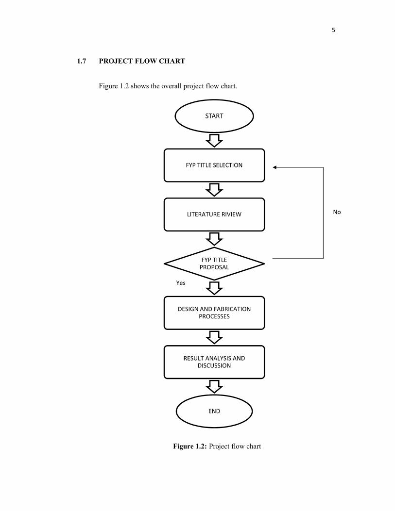
START
FYP TITLE SELECTION
LITERATURE RIVIEW
FYP TITLE PROPOSAL
DESIGN AND FABRICATION PROCESSES
RESULT ANALYSIS AND DISCUSSION
END
1.7 PROJECT FLOW CHART
Figure 1.2 shows the overall project flow chart.
Figure 1.2: Project flow chart
No
Yes

6
CHAPTER 2
LITERATURE REVIEW
2.1 BASIC CHARACTERISTIC OF SHEET METAL FORMING PROCESS
Sheet metals forming refer to various processes used to convert sheet metal into
different shapes for a large variety of finished parts such as aluminium cans and
automobile body parts. Deep drawing process is one of the forming processes. The key
to the formability of sheet metal is its ductility. Sheet metal parts are usually made in a
cold condition but sheet metal parts also are formed in a hot condition as the material
will have a lower resistance in hot condition. Blanks are very often used as the initial
materials during sheet metal forming. The shape of a part generally corresponds to the
shape of the tool (Vukota Boljanovic, 2004). Sheet metal forming process is used for
both serial and mass production. Their characteristics are:
High productivity
Highly efficient use of material Easy servicing of machines
The ability to employ worker with relatively less basic skills Advantageous economic aspects
2.2 MATERIAL SELECTION FOR DIE FABRICATION
Selection of materials for die components is an important activity during die
design stage in stamping industries. The knowledge base on the system can be modified
depending upon the availability of new materials and advancement in technology. A
long life cycle time of all the die components is desired to reduce the maintenance or
repairing cost.

7
2.2.1 Type of Tool Steel
The key components of a deep draw die are the ability of tool steel to withstand
the high shock loading involved and to resist the abrasive forces involved. Tool steel
refers to a variety of carbon and alloy steels that are particularly well suited to be made
into tools. Their suitability comes from their distinctive hardness, resistance to abrasion,
their ability to hold a cutting edge, and their resistance to deformation at elevated
temperatures. Base from the advantages, tool steel is suitable to be uses in this project.
Tool steels are made to a number of grades for different applications. Choice of grade
depends on whether a keen cutting edge is necessary, as in stamping dies, or whether
the tool has to withstand impact loading and service conditions encountered with such
hand tools as axes, pickaxes, and quarrying implements. In general, the edge
temperature under expected use is an important determinant of both composition and
required heat treatment. The higher carbon grades are typically used for such
applications as stamping dies or metal cutting tools (Vukota Boljanovic, 2004). In this
project the JIS SKD11 tool steel is chosen as it is a high-carbon-chromium alloy tool
steel which is soft annealed to about HB210. It has a good wear resistance and
machinability after heat treatment and is suitable for making long life high precision
cold work dies.
2.3 MECHANICS OF DEEP DRAWING
2.3.1 Die Concept
Deep drawing die is a metalworking tool that is designed and built to convert
raw material into parts that conform to blueprint specifications. Before proceeding with
the fabrication, the fundamental of deep drawing process must be known first. In deep
drawing, dies are placed into a stamping press and when the stamping press moves up,
the die opens. As the stamping press moves down, the die closes. The raw material or
blank moves through the die while the die is open, being fed into the die in a precise
amount with each stroke of the press. As the die closes, the die performs its work on the
metal. The greater the die cavity depth, the more blank material has to be pulled down
8
into the die cavity and the greater the risk of wrinkling in the walls and flange of the
part. In stamping, most of the final part is formed by stretching over the punch although
some material around the sides may have been drawn inwards from the flange. As there
is a limit to the stretching that is possible before tearing, stamped parts are typically
shallow. To form deeper parts, much more material must be drawn inwards to form it.
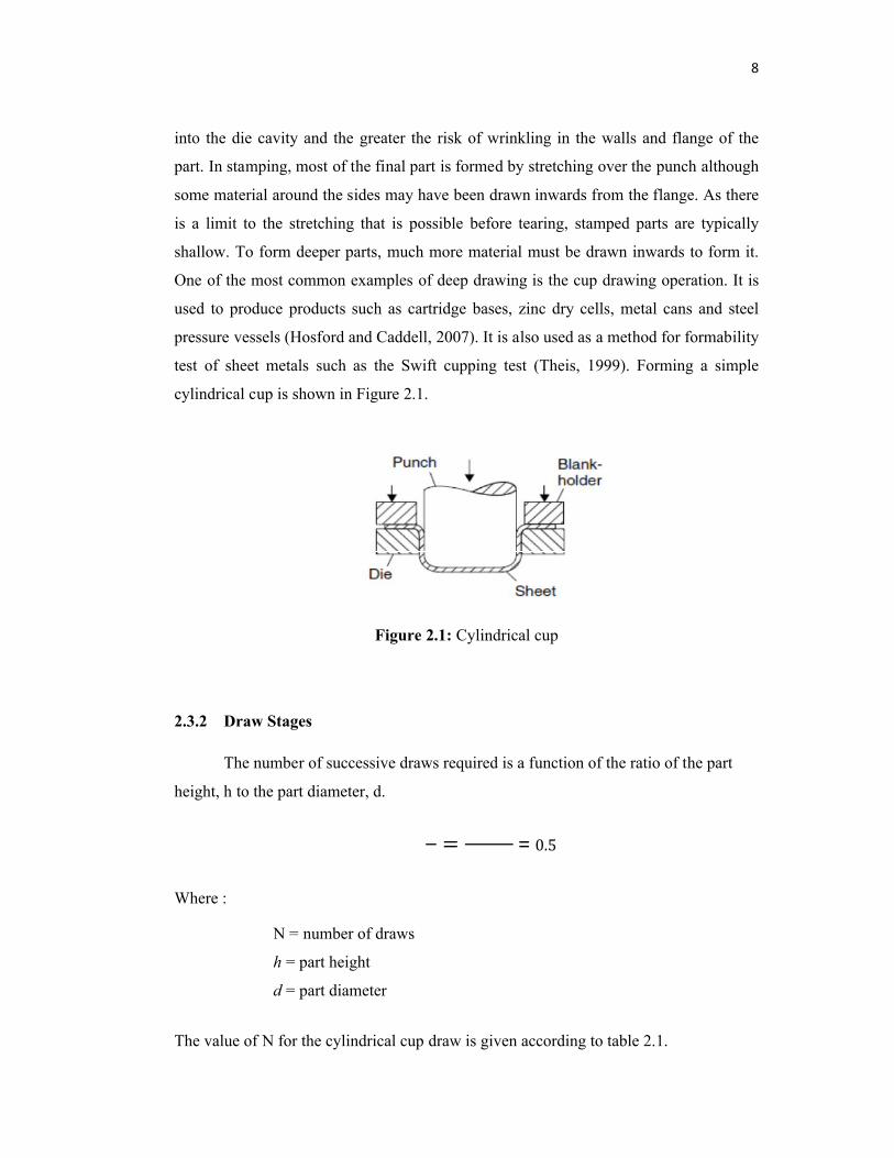
One of the most common examples of deep drawing is the cup drawing operation. It is
used to produce products such as cartridge bases, zinc dry cells, metal cans and steel
pressure vessels (Hosford and Caddell, 2007). It is also used as a method for formability
test of sheet metals such as the Swift cupping test (Theis, 1999). Forming a simple
cylindrical cup is shown in Figure 2.1.
Figure 2.1: Cylindrical cup
2.3.2 Draw Stages
The number of successive draws required is a function of the ratio of the part
height, h to the part diameter, d.
= = 0.5
Where :
N = number of draws
h = part height
d = part diameter
The value of N for the cylindrical cup draw is given according to table 2.1.

9
Table 2.1 Number of draws (n) for a cylindrical cup
ℎ <0.6 0.6 to 1.4 1.4 to 2.5 2.5 to 4.0 4.0 to 7.0 7.0 to 12
N 1 2 3 4 5 6
Source: Vukota Boljanovic (2004)
Therefore, in this project only one drawing operation is needed to produce the cup
according to table 2.1 as the N value is 1.
2.3.3 Die Clearance and Radius
One of the factors that must be considered in determining a die dimensions is the
amount of clearance (Fig. 2.2) between the punch and die members. A proper clearance
of the die will give the desired force during the stamping process. The radius degree of
the punch and die cavity edges control the flow of blank material into the die cavity.
Wrinkling in the cup wall can occur if the radius of the punch and die cavity edges are
too large. If the radius is too small, the blank is prone to tearing because of the high
stresses. Proper clearance application also depends on the material degree of hardness
and thickness. (Vukota Boljanovic, 2004).
Figure 2.2: Punch & die clearance
Source : Vukota Boljanovic 2004

10
Table 2.2 illustrates the absolute value for clearance depending on the type and
thickness of the material.
Table 2.2: Absolute value for clearance
Source: Vukota Boljanovic (2004)

11
Punch diameter:
Where:
C, Clearance per side = 1.1 (thickness 1mm)
Dm = diameter of die
dp = diameter of punch
1.1 = 50 −2 = 47.80 mm
Punch radius:
In this project, a punch with 5mm radius is desired as the final cylindrical cup radius.

12
2.3.4 Blank Size
The deep drawing process requires a blank. It’s a part of metal stamping process
(Vukota Boljanovic, 2004). The blank is a piece of sheet metal, typically a disc or
rectangle, which is pre cut from the stock material and will be formed into the part
(Wang Xi & Cao J, 2000). The volume of the developed blank before drawing should
be the same as the volume of the cup after drawing. Provided that the thickness of the
material remains unchanged, the area of the workpiece will not change. Thus, the blank
diameter may be found from the area of blank before drawing. The cup in Figure 2.3
may be broken into matching components and Figure 2.4 illustrates the area of each
component that need to be calculated.
Figure 2.3: Draw element Figure 2.4: Draw area

13
Figure 2.5 shows the cup size to calculate total surface area.
Figure 2.5: Cylindrical cup
Total Surface Area = Sum of Element I to V
Element I (Ring) Element II (Inner Fillet)
Area = 0.7854 x (D2 – d2) Area = (4.935 x R x D) – (6.283 x R2)= 0.7854 x (702 – 602) = (4.935 x 5 x 60) – (6.283 x 52)= 1021.02 mm2 = 1323.4 mm2
Element III (Cylinder) Element IV (Outer Fillet)
Area = 3.1416 x D x H Area = (4.935 x R x D) + (6.283 x R2)= 3.1416 x 50 x 25 = (4.935 x 5 x 40) + (6.283 x 52)= 3927 mm2 = 1144.1 mm2
Element V (Disc)
Area = 0.7854 x D2
= 0.7854 x 402
= 1256.7 mm2
Total surface area = Sum of Element I to V= 8672.22mm2
Area of flat blank = 0.7854 x D2
Diameter of flat blank = √ Area / 0.7854= √ 8672.22/ 0.7854= 105.08mm= 105mm
25
70

14
2.3.5 Limit Draw Ratio
In deep drawing, the limits for the permissible deformation are set by the draw
ratio. The draw ratio is used to:
i. Determine how many drawing operations are necessary to produce a
drawn part;
ii. Judge the drawability of deep drawing steels;
iii. Determine the correction value n = f (draw ratio) to calculate the drawing
force.
The critical forming parameter for cylindrical cup drawing is the limit drawing
ratio (LDR), which is the ratio of the maximum blank diameter to punch diameter that
can be drawn in one draw operation.
LDR = maximum blank diameter, D = 105 = 2.2punch diameter, d 47.8
Table 2.3: Mean values for βpermissable
Source: Heinz Tschaetsch (2006)