reduced wiring system devicenet compliant si unit...2.installation on equipment in conjunction with...
TRANSCRIPT

No.EX##-OMJ0007
Reduced wiring system (DeviceNet compliant SI unit)
PRODUCT NAME
EX180-SDN※ Series MODEL/ Series

No.EX##-OMJ0007
Table of Contents
Safety Instructions 2 Product Summary 8 Model indication method / How to order 8 Parts and functions description 9 Mounting / Installation 10 Installation 10 Wiring method 11 Setting 13 Mounting of objects 15 Specification 23 Specifications 23 Dimensions 25 Maintenance 26 Troubleshooting 27 Troubleshoot 27
-1-

No.EX##-OMJ0007
Safety Instructions This manual contains essential information to prevent possible injury and damage to (users and other people, and property) and to ensure correct handling. Please confirm understanding the definition of the following messages (signs) before going on to read the text, and always follow the instructions. Also read carefully the instruction manual of relevant equipment or apparatus before use.
♦Indications
IMPORTANT MESSAGES Read this manual and follow its instructions. Signal words such as WARNING, CAUTION and NOTE, will be followed by important safety information that must be carefully reviewed.
Indicates a potentially hazardous situation which could result in death or serious injury if you do not follow instructions.
Indicates a potentially hazardous situation which if not avoided, may result in minor injury or moderate injury.
NOTE Gives you helpful information.
♦Operator
♦This operation manual has been written for those who have knowledge of machinery and apparatus that use pneumatic equipment and have full knowledge of assembly, operation and maintenance of such equipment.
♦Please read this operation manual carefully and understand it before assembling, operating or providing maintenance to the SI Unit.
♦Usage Restrictions
♦This product is designed for use in general equipment for factory automation. Never use this product with equipment or apparatus that directly concerns human lives*1, or which malfunction or failure can cause a huge loss. *1: Equipment or apparatus that directly matters human lives means the following:
• Medical equipment such as life support systems or equipment used in operating rooms • Compulsory equipment required by law such as the Fire Prevention Law, Construction Law and etc. • Equipment or apparatus that conforms with those mentioned above.
♦Contact our sales department when plans are made for the product to be used for the system*2 including equipment that concerns itself with the safety of persons or that seriously affects the public. This usage needs special consideration*3. *2: The system including equipment that concerns itself with the safety of persons or that seriously affects
the public means the following: • Nuclear reactor control systems in nuclear power plants, safety protection systems or other systems
important for safety in nuclear power facilities • Driving control systems of mass transportation systems, and flight control systems • Equipment or apparatus that comes into contact with foods or beverages
*3: Special consideration means discussing usage with our engineers to establish a safe system designed as fool-proof, fail-safe, redundant and etc.
♦Special consideration of safety or maintainability should be taken to prevent hazard or loss caused by a failure or malfunction that is likely to occur in certain probability due to environmental stress (deterioration). The special consideration means to fully review the equipment or apparatus in design stage and to establish a backup system in advance such as a redundant system or fail-safe system.
-2-

No.EX##-OMJ0007
♦The compatibility of pneumatic equipment is the responsibility of the person who designs the pneumatic system or decides its specifications. Since the products specified here are used in various operating conditions, their compatibility with the specific pneumatic system must be based on specifications or after analysis and / or tests to meet your specific requirements.
♦Only trained personnel should operate pneumatically operated machinery and equipment. Compressed air can be dangerous if an operator is unfamiliar with it. Assembly, handling or repair of pneumatic systems should be performed by trained and experienced operators.
♦Do not service machinery / equipment or attempt to remove components until safety is confirmed. 1.Inspection and maintenance of machinery /equipment should only be performed after confirmation of
safe locked-out control positions. 2.When equipment is to be removed, confirm the safety process as mentioned above. Cut the supply
pressure for the equipment and exhaust all residual compressed air in the system. 3.Before machinery / equipment is re-started, take measures to prevent quick extensions of the cylinder
piston rod etc. (Bleed air info the system gradually to create back-pressure.) ♦Contact SMC if the product is to be used in any of the following conditions:
1.Conditions and environments beyond the given specifications, or if product is used outdoors. 2.Installation on equipment in conjunction with atomic energy, railway, air navigation, vehicles, medical
equipment, food and beverage, recreation equipment, emergency stop circuits, press applications, or safety equipment.
3.An application which has the possibility of having negative effects on people, property, or animals, requiring special safety analysis.
-3-

No.EX##-OMJ0007
♦Do not disassemble, modify (including change of printed circuit board) or repair. It may result in injury or failure.
♦Do not operate the product beyond specification range. Operation at a range that exceeds the specifications can cause a fire, malfunction, or damage to the unit. Verify the specifications before use.
♦Do not use the product in an atmosphere containing combustible, explosive or corrosive gas. It can cause a fire, explosion or corrosion. The unit is not designed as explosion-proof.
♦The following instructions must be kept when using the product in an interlocking circuit: • Provide double interlocking by another system such as mechanical protection • Check the product regularly to ensure proper operation Otherwise malfunction may cause an accident.
♦The following instructions must be kept during maintenance: • Turn off the power supply • Stop the supplied air, exhaust the residual pressure, and confirm the release to atmosphere
before performing maintenance Otherwise it may cause injury.
♦Perform proper functional checks after maintenance. Stop operation when an abnormality is observed such that the unit does not work properly. Safety may not be able to secured if unexpected incorrect operation occurs.
♦Provide grounding for securing safety and noise resistance of reduced-wiring system. Provide an individual grounding as possible, and place it near the unit to shorten the distance between the grounding and the unit.
-4-

No.EX##-OMJ0007
NOTE ♦Follow the instructions given below for selecting and handling reduced-wiring system :
♦Selection (Follow the installation, wiring, environment of use, adjustment, operation, and maintenance described below, too.)
∗Product specifications • Use the following UL recognized direct-current power supply for direct power supplies to
combine. (1) Limited voltage current circuit in accordance with UL508
A circuit whose power is supplied by secondary coil of a insulating transformer that meets the following conditions • Maximum voltage (with no load) : less than 30Vrms (42.4V peak) • Maximum current : (1) less than 8A(including when short circuited)
(2) limited by circuit protector (such as fuse) with the following ratings
No load voltage (V peak) Max. current rating (A) 0 ∼ 20 [V] 5.0
Above 20 to 30 [V] 100 / peak voltage
(2) A circuit using max. 30Vrms or less (Class-2 circuit), whose power is supplied by Class-2 power supply unit in accordance with UL1310, or Class-2 power supply unit in accordance with UL1585
• The reference of a power supply for SI unit is 0V for both power supplies for solenoid valves and DeviceNet.
• Operate reduced-wiring system with the specified voltage.
Operation with a voltage beyond specifications could cause malfunction or damage of the unit. • Reserve a space for maintenance
Keep space for maintenance for the layout of the unit. • Do not remove nameplate.
Otherwise maintenance error and misreading of an operation manual could cause damage or malfunction. It may also result in nonconformity to the safety standards.
♦Precautions on handling
∗Installation • Do not drop, hit or apply excessive shock to the unit.
Otherwise the unit could be damaged, and cause failure and malfunction. • Follow the specified tightening torque.
Excessive tightening torque can break screws. ∗Wiring (including plugging in/out of connector) • Do not bend the cables or apply excessive force to them by pulling or placing heavy load.
Wiring subject to bending or tensile stress could cause breakage of a cable.
-5-

No.EX##-OMJ0007
• Connect wires and cables correctly. Incorrect wiring could cause damage or malfunction to the reduced-wiring system.
• Do not connect wires while the power is supplied. Otherwise, the reduced-wiring system could be damaged or malfunction.
• Do not connect power cable or high-voltage cable in the same wiring route as the unit. Otherwise the wires to the reduced-wiring system can be interrupted with noise or induced surge voltagefrom power lines or high-voltage lines and malfunction could be caused. Separate wiring of the unit and each I/O device from that of power line and high voltage line.
• Verify the insulation of wiring. Insulation failure (interference with other circuit, poor insulation between terminals and etc.) could introduce excessive voltage or current to the reduced-wiring system or each I/O device and damage them.
• Separate power line for solenoid valves from power line for input and control unit. Otherwise wires can be interrupted with noise or induced surge voltage causing malfunction.
• Take proper measure against noise such as noise filter when the reduced-wiring system is incorporated in equipment or devices. Otherwise contamination with noise can cause malfunction.
∗Environment • Consider using the reduced-wiring system in operating environment suitable for enclosure.
In case of IP20, avoid use in the place where water and oil scatter. • Take sufficient shielding measures when the unit is installed.
Insufficient measures could cause malfunction or failure. Verify the effect of the measures after incorporation of the unit in equipment or devices: (1) A place where noise due to static electricity is generated (2) A place where electric field strength is high (3) A place where there is radioactive irradiation (4) A place near power line
• Do not use the unit near a place where electric surge is generated. Internal circuit elements of the reduced-wiring system can deteriorate or break when equipment generating a large surge (electromagnetic lifter, high frequency induction furnace, motor, etc.) is locatednear the reduced-wiring system. Provide surge preventives, and avoid interference with line for the equipment.
• Use the reduced-wiring system equipped with surge absorber when a surge-generating load such as solenoid valve is driven directly. Direct drive of a load generating surge voltage can damage reduced wiring system.
• Prevent foreign matters such as remnant of wires from entering the unit. Take proper measures for the remnant not to enter the reduced-wiring system in order to prevent failure or malfunction.
• Do not expose the reduced-wiring system to vibration and impact. Otherwise failure or malfunction could be caused.
• Keep the specified ambient temperature range. Otherwise malfunction could be caused. Do not use reduced-wiring system in a place where temperature suddenly changes even within the specified range.
• Do not expose the reduced-wiring system to heat radiation from a heat source located nearby. Malfunction could be caused.
∗Adjustment and Operation • Use precision screwdriver with for small flat blade for setting DIP switch. ∗Maintenance • Perform maintenance and check regularly.
Otherwise an unexpected malfunction of components could of the unit occur due to a malfunction of thewhole unit.
-6-

No.EX##-OMJ0007
• Perform a proper functional check. Stop operation when an abnormality is observed such that the device doesn't work properly. Otherwise an unexpected malfunction of the unit component can occur.
• Do not use solvents such as benzene, thinner or other to clean the reduced-wiring system. They could damage the surface of the body and erase the indication on the body. Use a soft cloth to remove stains. For heavy stains, use a cloth soaked with diluted neutral detergent and fully squeezed, then wipe up the stains again with a dry cloth.
-7-

No.EX##-OMJ0007
Product Summary EX180-SDN※ is a SI unit for SJ2000/ 3000 which can be connected to DeviceNet. The followings are the specification and instructions for handling.
Model indication method / How to order ・SI unit series EX180
・Accessory : Communuication
・Accessory : Power supply connector
-8-
No.EX##-OMJ0007
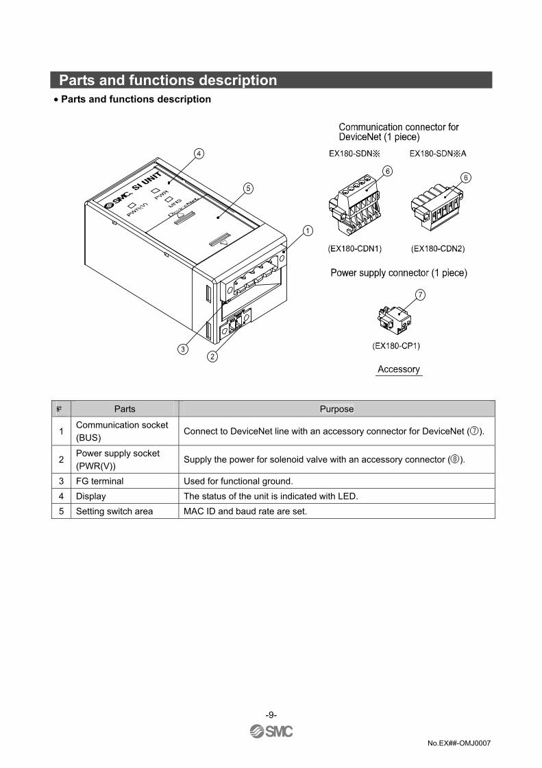
Parts and functions description • Parts and functions description
Parts Purpose
1 Communication socket (BUS)
Connect to DeviceNet line with an accessory connector for DeviceNet (⑦).
2 Power supply socket (PWR(V))
Supply the power for solenoid valve with an accessory connector (⑧).
3 FG terminal Used for functional ground. 4 Display The status of the unit is indicated with LED. 5 Setting switch area MAC ID and baud rate are set.
-9-

No.EX##-OMJ0007
Mounting / Installation ♦Installation • Applicable manifold valve
The SI unit series EX180 can have the following manifold valve only. • Manifold
• Series SJ2000/3000 * Refer to a catalog for each valve series and Technical Specifications for the detail of the solenoid valve
and manifold.
• Mounting to the manifold
1. Put the mounting guide of the SI unit case to the manifold groove. 2. Slide the 2 locks on the top of the manifold.
-10-

No.EX##-OMJ0007
♦Wiring method • Internal circuit • NPN output
• PNP output
※ As EX180-SDN2 has 16 output points, OUT16 to OUT31 will not be used.
-11-

No.EX##-OMJ0007
1. Communication wiring
The method to connect DeviceNet dedicated cable to the communication connector of SI unit for DeviceNet is shown on the following table. (1) Make sure to connect the signal cables to designated pins (Refer to Fig.1).
Tighten properly with 0.5 to 0.6[N • m] of tightening torque.
(2) Make sure to connect a "Terminating resistor" between "CAN_H" and "CAN_L" of the unit at both ends of DeviceNet system (Refer to Fig.2). The speification of the resistance at the end is 121Ω ± 1%, 1/4W.
(3) Refer to Fig.3 about how to connect to the unit.
-12-

No.EX##-OMJ0007
2. Power supply wiring
Connect power supply wiring to the power supply connector (1pcs) which are delivered as accessory of the SI unit. Power supply structure consists of 2 systems, but it can be used with both single power supply and dual power supply. Make sure to connect the designated pin (Refer to Fig.4 and Fig.5). Tighten properly with 0.22 to 0.25[N • m] of tightening torque. Note D type grounding (Third-type grounding) should be performed for FG terminal.
Setting • Settings for display
Display Meaning
PWR (V) The solenoid valve power supply is supplied with specified voltage : Lights up The solenoid valve power supply is not supplied withspecified voltage : Goes off
PWR
Power supply for the DeviceNet communication is supplied : Light up Power supply for the DeviceNet communication is not supplied : Goes off
MNS
The power for DeviceNet communication is cut, or during off-line status or duplication check for MAC ID : Goes off While waiting for I/O connection (with on-line status): Green blinks When I/O connection is established (with on-line status) : Green lights up On I/O connection • time out (slight communication error) : Red blinks On MAC ID duplication error or BUS OFF error (serious communication error) : Red lights up
-13-

No.EX##-OMJ0007
• Switch setting
• Make sure that switch setting is done with power supply turned off. • Open the cover, and use a precision screwdriver with small flat blade when setting DIP switch, etc.
-14-

No.EX##-OMJ0007
Mounting of Objects • Mounting of objects
This SI unit, which selects the pneumatic valve among the various device types, covers the DeviceNet object classes below.
Class code Object type 01h Identity 02h Message Router 03h DeviceNet 04h Assembly 05h DeviceNet Connection 09h Discrete Output Point 0Fh Parameter 2Bh Acknowledge Handler 64h SMC SI (proper to vendor)
1. Identity Object (Class ID: 01h)
1-1 Class attribute
1-2 Class common service
Service code Description - -
1-3 Instance attribute
1-4 Instance common service Service code Description
05h Reset 0Eh Get_Attribute_Single
1-5 Peculier service None
-15-
ID Access rule Dscrp. Value- - - -
ID Access rule Description Value 1 Get Vender ID 07 2 Get Device Type 27
3 Get Product Code 101 : EX180-SDN1,SDN1A106 : EX180-SDN2,SDN2A
4 Get Revision 1.1 5 Get Status - 6 Get Serial Number Per unit 7 Get Product Name Valve Manifold SIU

No.EX##-OMJ0007
2.Message Router Object (Class ID: 02h) 2-1 Class attribute
ID Access rule Descrip. Value- - - -
2-2 Class common service
Service code Description - -
2-3 Instance attribute
ID Access rule Descrip. Value- - - -
2-4 Instance common service
Service code Description - -
2-5 Peculier service None
3.DeviceNet Object (Class ID: 03h)
3-1 Class attribute ID Access rule Description Value1 Get revision 2
3-2 Class common service
Service code Description 0Eh Get_Attribute_Single
3-3 Instance attribute
ID Access rule Description Value1 Get/Set *1 MAC_ID - 2 Get/Set *1 Baud Rate - 3 Get/Set BOI - 4 Get/Set Buss-off Counter - 5 Get Allocation Information - 6 Get MAC ID Switch Changed - 7 Get Baud Rate Switch Changed - 8 Get MAC ID Switch Value - 9 Get Baud Rate Switch Value - 10 Set Quick Connect -
*1: “Set” is available in SW mode
-16-

No.EX##-OMJ0007
3-4 Instance common service
Service code Description 0Eh Get_Attribute_Single 10h Set_Attribute_Single
3-5 Peculier service
Service code Description 4Bh Allocate_Master/Slave_Connection_set 4Ch Release_Group_2_Identifier_Set
4. Assembly Object (Class ID: 04h)
4-1 Class attribute
ID Access rule Dscrp. Value- - - -
4-2 Class common service
Service code Description - -
4-3 Solenoid Output Assembly Instance
Instance Type Description 35 Output 16 Solenoid Output Points 37 Output 32 Solenoid Output Points
4-4 Instance common service
Service code Description 0Eh Get_Attribute_Single
4-5 Peculier service None
5.DeviceNet Connection Object (Class ID: 05h)
5-1 Class attribute
ID Access rule Dscrp. Value- - - -
5-2 Class common service
Service code Description - -
-17-

No.EX##-OMJ0007
5-3 Instance attribute 1 (Explicit message) ID Access rule Description Value 1 Get State - 2 Get instance_type 00 3 Get transportClass_trigger 83h 4 Get produced_connection_id - 5 Get consumed_connection_id - 6 Get initial_comm_characteristics 21h 7 Get produced_connection_size FFFFh8 Get consumed_connection_size FFFFh9 Get/Set expected_packet_rate - 12 Get/Set watchdog_timeout_action - 13 Get produced_connection_path_length 0 14 Get produced_connection_path None 15 Get consumed_connection_path_length 0 16 Get consumed_connection_path None 17 Get production_inhibit_time 0
5-4 Instance attribute 2 (I/O: Poll message)
ID Access rule Description Value 1 Get State - 2 Get instance_type 01h
3 Get transportClass_trigger 83h : Poll 80h : Cos/Cylic-Unacknowledged 83h : Cos/Cylic-Acknowledged
4 Get produced_connection_id - 5 Get consumed_connection_id - 6 Get initial_comm_characteristics 01h 7 Get produced_connection_size 0Byte
8 Get consumed_connection_size 4 : EX180-SDN1,EX180-SDN1A 2 : EX180-SDN2,EX180-SDN2A
9 Get/Set expected_packet_rate - 12 Get/Set watchdog_timeout_action - 13 Get produced_connection_path_length 0 14 Get produced_connection_path None 15 Get consumed_connection_path_length 6
16 Get consumed_connection_path 20h 04h 24h xxh 30h 03h
25 : EX180-SDN1,EX180-SDN1A 23 : EX180-SDN2,EX180-SDN2A
17 Get production_inhibit_time 0
-18-

No.EX##-OMJ0007
5-5 Instance attribute 4 (I/O: Cos/Cyclic message) ID Access rule Description Value 1 Get State - 2 Get instance_type 01 (I/O)
3 Get transportClass_trigger
13h : Cos- Acknowledged 10h : Cos- Unacknowledged 03h : Cylic- Acknowledged 00h : Cyclic- Unacknowledged
4 Get produced_connection_id -
5 Get consumed_connection_id -
6 Get initial_comm_characteristics 01h : Acknowledged 0Fh : Unacknowledged
7 Get produced_connection_size 0Byte 8 Get consumed_connection_size 0Byte 9 Get/Set expected_packet_rate -
12 Get/Set watchdog_timeout_action -
13 Get produced_connection_path_length 0
14 Get produced_connection_path None
15 Get consumed_connection_path_length 4 : Acknowledged 0 : Unacknowledged
16 Get consumed_connection_path 20h 2Bh 24h 01h (Acknowledged)None (Unacknowledged)
17 Set production_inhibit_time -
5-6 Instance common service
Service code Description 0Eh Get_Attribute_Single 10h Set_Attribute_Single 05h Reset
6.Discrete Output Object (class ID: 09h)
6-1 Class attribute
ID Access rule Dscrpt. Value- - - -
6-2 Class common service
Service code Description - -
-19-

No.EX##-OMJ0007
6-3 Instance attribute ID Access rule Description Value 3 Get/Set Value 0 : OFF, 1: ON
4 Get Status 0 : OK 1 : Valve power voltage error or valve power fuse breakage
5 Set Fault Action 0 : Fault Value 1 : Maintaining output
6 Set Fault Value 0 : OFF, 1: ON
7 Set Idle Action 0 : Idle Value 1 : Maintaining output
8 Set Idle Value 0 : OFF, 1: ON
6-4 Instance common service
Service code Description 0Eh Get_Attribute_Single 10h Set_Attribute_Single
6-5 Perculier service None
7. Parameter Object (Class ID: 0Fh)
7-1 Class attribute
ID Access rule Descrption Value 2 Get Max Instance 6 8 Get Parameter Class Descriptor 1 9 Get Configuration Assembly Instance 0
7-2 Instance attribute 1: SOLV Status
ID Access rule Description Value
1 Get Parameter Value 0 : Normal valve power voltage 1 : Valve power voltage error
2 Set Link Path Size 6 Link Path 21h 64h 24h 01h 31h 64h Segment type/port - 3 Set Segment Address -
4 Get Descriptor 30h 5 Get Data Type C1h 6 Get Data Size 1
-20-

No.EX##-OMJ0007
7-3 Instance attribute 2 : SOLV Fuse Status ID Access rule Description Value
1 Get Parameter Value 0 : Normal valve power fuse 1 : Valve power fuse breakage
2 Set Link Path Size 6 Link Path 21h 64h 24h 01h 31h 65h Segment type/port - 3 Set Segment Address -
4 Get Descriptor 30 5 Get Data Type C1 6 Get Data Size 1
7-4 Instance attribute 5 : selecting Hold/Clear (Time Out)
ID Access rule Description Value
1 Get Parameter Value 0 : Effective DIP switch 1 : Effective Fault Action
2 Set Link Path Size 6 Link Path 21h 64h 24h 01h 31h 68hSegment type/port - 3 Set Segment Address -
4 Get Descriptor 20h 5 Get Data Type C1h 6 Get Data Size 1
7-5 Instance attribute 6 : selecting Hold/Clear (Connection Delete)
ID Access rule Description Value
1 Get Parameter Value 0 : Effective DIP switch 1 : Effective Fault Action
2 Set Link Path Size 6 Link Path 21h 64h 24h 01h 31h 69hSegment type/port - 3 Set Segment Address -
4 Get Descriptor 20h 5 Get Data Type C1h 6 Get Data Size 1
8. Acknowledge Handler Object (Class ID : 2Bh)
8-1 Class attribute
ID Access rule Dscrpt. Value- - - -
-21-

No.EX##-OMJ0007
8-2 Class common service
Service code Description - -
8-3 Instance attribute
ID Access rule Description Value1 Set Acknowledge Timer - 2 Get/Set Retry Limit - 3 Get COS Producing Connection 4
8-4 Instance common service
Service code Description 0Eh Get_Attribute_Single 10h Set_Attribute_Single
9.SMC SI Object (Class ID: 64h)
9-1 Class attribute
ID Access rule Dscrpt. Value- - - -
9-2 Class common service
Service code Description - -
9-3 Instance attribute
ID Access rule Description Value
100 Get SOLV Status 0 : OK 1 : Valve power supply error
101 Get SOLV Fuse Status 0 : OK 1 : Valve power supply fuse breakage
104 Get/Set Hold/Clear (Time Out) 0 : Effective DIP switch (initial value) 1 : Effective Fault Action
105 Get/Set Hold/Clear (Connection Delete) Setting
0 : as per the setting of ID104 (initial value)1 : Clear (Specification of DeviceNet)
9-4 Instance common service
Service code Description 0Eh Get_Attribute_Single 10h Set_Attribute_Single
9-5 Peculier service None
-22-

No.EX##-OMJ0007
Specification ♦Specifications
General specification
Item Specifications
Rated voltage 24VDC
Power supply voltage range Power supply for DeviceNet : 11VDC to 25VDC Power supply for solenoid valve : 24VDC + 10%/-5%
Output points EX180-SDN1, SDN1A : 32 points EX180-SDN2, SDN2A : 16 points
Short circuit protection Provided
Current consumption 70mA or less
Tolerant instantaneous power failure
10msec. or less
Enclosure IP20
Withstand voltage 500VAC 1min. (Between FG and external terminal block)
Insulation resistance 10MΩ or more (500VDC, between FG and external terminal block)
Ambient tempareture Operating temperature : -10 to +50 Storage : -20 to +60
Ambient humidity 35% to 85%RH (no dew concentration)
Vibration proof
5Hz to 9Hz (constant amplitude) 1.75mm 9Hz to 150Hz (constant acceleration) 4.9m/s2
Practice the vibration test as per JIS B3502 and IEC61131-2 to X, Y, and Z directions for 3 times each
Shock resistant 147m/s2 Practice the shock test as per JIS B3502 and IEC61131-2 to X, Y, and Z directions for 3 times each
Environm
ent proof Atmosphere No corrosive gas
Standards UL/CSA (E209424), CE marking
Weight 110g or less (including accessories)
-23-

No.EX##-OMJ0007
Communication specification
Item Specifications
Applicable system DeviceNet Volume1 (Edtion2.1) Volume3 (Edtion1.1)
Slave type Group2 Only Server
Device type 27 (Pneumatic valve)
Product code 101 : EX180-SDN1, SDN1A 106 : EX180-SDN2, SDN2A
Vendor ID 7 (SMC Corp.)
Applicable message
Duplicate MAC ID Check Message Unconnected Explicit Message Explicit Message COS/Cyclic I/O Message
Setting range of MAC ID 0 ot 63
Communication speed 125kbps 250kbps 500kbps
Thick cable 500m or less 250m or less 100m or less Maximum cable length for network Thin cable 100m or less
156m or less 78m or less 39m or less Whole length of branch cable
Note: The maximum length of each branch cable is 6m.
Occupied byte EX180-SDN1, SDN1A : 4 bytes for output, 0 byte for input EX180-SDN2, SDN2A : 2 bytes for output, 0 byte for input
-24-

No.EX##-OMJ0007
♦Dimensions (unit : mm)
-25-

No.EX##-OMJ0007
Maintenance ♦Maintenance • Mounting and wiring
Item to inspect Criteria Countermeasure
Are connectors (communication, power supply) of SI unit securely connected?
No looseness. Tighten the connector. (refer to this Technical Specifications)
Are the terminating resistor securelyconnected to the both ends of the DeviceNet system? (in case this system is at the end of the network)
No looseness. Tighten the connector.
Isn’t the connecting cable broken. No appearance error. If any error is found on the appearance, replace the cable.
• Replacement parts Item to inspect Criteria Countermeasure
Cable for moving part (when used)
No error on the appearance and conductive resistance value. (For the resistance value, check for exceeding of specified range and balance change in pair cable.)
If any error is found on the appearance or the conductive resistance, replace the cable. See the specification of a cable to be used for the conductive resistance.
SI unit No error in operation and display
If any error is found in the operation or on the display, replace the unit.
• Power supply Item to inspect Criteria Countermeasure
Does the voltage satisfy the specified range? Measure the voltages at the both sides of a power supply for DeviceNet.
11VDC to 25VDC Investigate into the cause of voltage fluctuation, and take a countermeasure against it.
Does the voltage satisfy the specified range? Measure the voltages at the both sides of the power supply for solenoid valves.
24VDC +10% / -5% Investigate into the cause of voltage fluctuation, and take a countermeasure against it.
-26-

No.EX##-OMJ0007
Troubleshooting ♦Troubleshoot
Applicable model : EX180-SDN* If a SI unit gets an operation failure, look for the problem using the following flow chart. If any cause of the problem cannot be found, and a new SI unit can operate well after replaced with the old one, the failure of SI unit is conceivable. As the failure of SI unit may happen due to the operation environment (network construction etc), consult us about the countermeasure against that case.
-27-
Yes No
Solenoid valve’s malfunction.
Solenoid valve’s failure
Only the LED at a solenoid valve
is lit up.
See Trouble No. 2
SI unit has no error.
PWR_LED at SI unit goes off.
PWR(V)_LED at SI unit goes off.
MNS_LED at SIunit goes off.
Green light of MNS _LED at SIunit is blinking.
Solenoid valve’s malfunction.
See Trouble No. 1
See Trouble No. 3
See Trouble No. 4
See Trouble No. 5
See Trouble No. 6
See Trouble No. 7
Red light of MNS _LED at SI
unit is lit up.
Red light of MNS _LED at SI unit is blinking.
No.EX##-OMJ0007
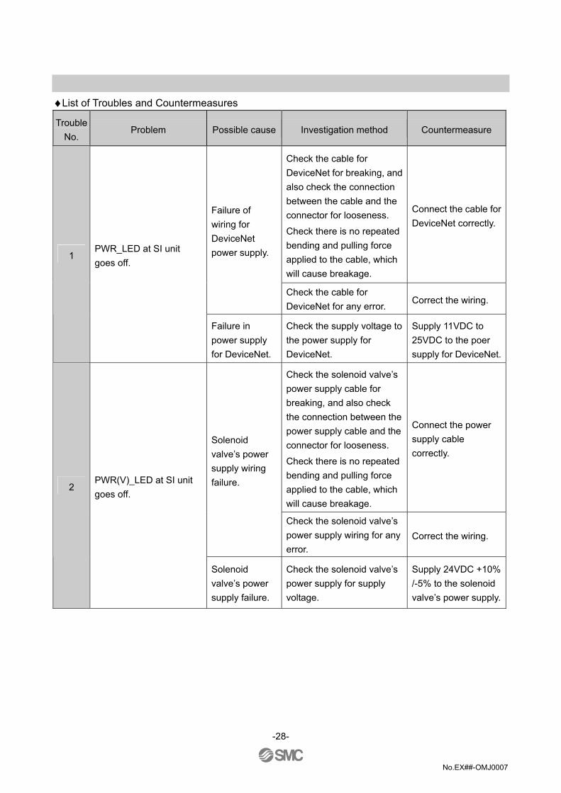
♦List of Troubles and Countermeasures
Trouble No.
Problem Possible cause Investigation method Countermeasure
Check the cable for DeviceNet for breaking, and also check the connection between the cable and the connector for looseness.
Check there is no repeated bending and pulling force applied to the cable, which will cause breakage.
Connect the cable for DeviceNet correctly.
Failure of wiring for DeviceNet power supply.
Check the cable for DeviceNet for any error. Correct the wiring.
1 PWR_LED at SI unit goes off.
Failure in power supply for DeviceNet.
Check the supply voltage to the power supply for DeviceNet.
Supply 11VDC to 25VDC to the poer supply for DeviceNet.
Check the solenoid valve’s power supply cable for breaking, and also check the connection between the power supply cable and the connector for looseness.
Check there is no repeated bending and pulling force applied to the cable, which will cause breakage.
Connect the power supply cable correctly.
Solenoid valve’s power supply wiring failure.
Check the solenoid valve’s power supply wiring for any error.
Correct the wiring.
2 PWR(V)_LED at SI unit goes off.
Solenoid valve’s power supply failure.
Check the solenoid valve’s power supply for supply voltage.
Supply 24VDC +10% /-5% to the solenoid valve’s power supply.
-28-

No.EX##-OMJ0007
Trouble No.
Problem Possible cause Investigation method Countermeasure
Failure in master station's power supply
Check if power is supplied to the master station.
Supply power for the master station properly.
Failure in
wiring for communication
Check the cable for DeviceNet for breaking, and also check the connection between the cable and the connector for looseness.
Check there is no repeated bending and pulling force applied to the cable, which will cause breakage.
Changed station number setting.
Check the cable for DeviceNet for any error.
Connect the cable for DeviceNet correctly.
Correct the wiring.
Communication failure.
Check the existence of equipment and high voltage line, which cause noise, around the communication and power supply lines.
Separate the cables for DeviceNet and power from the noise sources.
3 MNS_LED at SI unit goes off.
Checking for MAC ID overlapis in process.
Check if the master station and the slave station overlap with MAC ID.
Set MAC ID correctly.
-29-

No.EX##-OMJ0007
Trouble No.
Problem Possible cause Investigation method Countermeasure
MAC ID duplication
Check there is no difference between the speed settings for SI unit and the one for the master station and the slave stations.
Set MAC ID correctly.
Check the length of wiring for communication versus the communication speed, exsitance of terminal resistances at the both end of trunk, and the use of DeviceNet cable.
Wire and Set correctly.
Check the existence of equipment and high voltage line, which cause noise, around the communication and power supply lines.
Separate the cables for DeviceNet and power from the noise sources.
Check the cable for DeviceNet for breaking, and also check the connection between the cable and the connector for looseness.
Check there is no repeated bending and pulling force applied to the cable, which will cause breakage.
Connect the cable for DeviceNet correctly.
BUS OFF error
Check there is no difference between the speed settings for SI unit and the one for the master station and the slave stations.
Set the communication speed correctly.
4 Red light of MNS _LED at SI unit is lit up.
Failure in communication device
SI unit has an error which cannot be restored.
Replace the SI unit with a new one.
-30-

No.EX##-OMJ0007
Trouble No.
Problem Possible cause Investigation method Countermeasure
Check the length of wiring for communication versus the communication speed, exsitance of terminal resistances at the both end of trunk, and the use of DeviceNet cable.。 5
Red light of MNS_LED is blinking.
I/O connection time-out
Check the existence of equipment and high voltage line, which cause noise, around the communication and power supply lines.
Wire and Set correctly.
Separate the cables for DeviceNet and power from the noise sources.
Check the cable for DeviceNet for breaking, and also check the connection between the cable and the connector for looseness.
Check there is no repeated bending and pulling force applied to the cable, which will cause breakage.
Check there is no difference between the speed settings for SI unit and the one for the master station and the slave stations.
Connect the cable for DeviceNet correctly.
Set the communication speed correctly.
Check if power is supplied to the master station.
Supply power to the master station properly.
6 Green light of MNS_LED of SI unit is blinking.
Waiting for I/O connection (off-line status)
Wating for establishing connection with the slave station.
Check if MAC ID and communication speed for the slave stations are set correctly.
-31-

No.EX##-OMJ0007
Trouble No.
Problem Possible cause Investigation method Countermeasure
Solenoid valve failure.
Check the operation with another solenoid valve, or check the troubleshooting for a solenoid valve.
Check the troubleshooting for a solenoid valve, or consult our responsible division.
Connection failure between SI unit and manifold solenoid valves.
Check the connector between SI unit and manifold solenoid valves for the connection failure such as a bent pin
Correct the connection between SI unit and manifold solenoid valves.
The solenoid valve won’t work.
Check the total output numbers from the solenoid valves connected to a manifold are the same or less than the maximum output numbers from SI unit.
The output numbers from the solenoid valves connected to a manifold must be the same or less than the maximum output numbers from SI unit. EX180-SDN1 and EX180-SDN1A :32 points at max.
EX180-SDN2 and EX180-SDN2A :16 output at max.
7 Solenoid valve malfunction.
HOLD setting for the solenoid valve
Check the HOLD/CLR setting of SI unit.
Set HOLD/CLR setting correctly.
Note : If the red light of MNS_LED illuminates, SI unit will not be restored automatically even if the cause of the red light is solved. For that case, turn on the power supply for DeviceNet of SI unit again.
-32-

No.EX##-OMJ0007
Revision history
URL http://www.smcworld.com Note: Specifications are subject to change without prior notice and any obligation on the part of the manufacturer. The descriptions of products shown in this document may be used by the other companies as their trademarks. © 2005 SMC Corporation All Rights Reserved