reduced chemical kinetic mechanisms for methane …cfdbib/repository/wn_cfd_10_17.pdf · reduced...
TRANSCRIPT

Reduced chemical kinetic mechanismsfor methane combustion
in O2/N2 and O2/CO2 atmosphere
J. Bibrzycki1 and T. Poinsot21 Corresponding author: [email protected], Silesian University of Technology,
Institute of Thermal Technology, 22 Konarskiego St., 44-100 Gliwice, Poland2 Universite de Toulouse, IMFT (Institut de Mecanique des Fluides de Toulouse)
Allee C. Soula, F-31400 Toulouse, France
Abstract
Two reduced mechanisms (2S-CM2 and J-L) have been tested for a conventional air-methane com-bustion. Whereas, existing (2S-CM2 and J-L) schemes and refined ones (2S-CM2-JB2 and J-L-JB)were verified using detailed chemistry computations, for specified oxy-fuel conditions. Results for theair-methane case, obtained for the J-L scheme and for the GRI Mech, are in general in better agree-ment than those evaluated for the 2S-CM2. Large disagreement between detailed chemistry calcula-tions and results obtained for J-L and 2S-CM2 global schemes, for the oxy-fuel combustion, was foundfor freely propagating 1D laminar premixed flames. Therefore, two new major schemes were evalu-ated (2S-CM2-JB2 and J-L-JB). Modified schemes improved the agreement with the detailed mecha-nism considerably, for both considering compositions of the oxidizer (Xoxid
O2= 0,385/Xoxid
CO2= 0,615 and
XoxidO2
= 0,28/XoxidCO2
= 0,72).
INTRODUCTIONCarbon dioxide emission reduction has become one of the main concern last years, due to the standpointof most of scientists, who work on climate change that a direct connection between global temperatureincrease and anthropogenic greenhouse gases emission exists. Carbon dioxide is a specie, which emis-sion cannot be avoided during combustion of the fuel containing carbon. Therefore, emission reductioncan be only done through sequestration. In order to underground storage of CO2, this specie has to beseparated from flue gases, which contain mainly nitrogen, what is a very expensive process. One ofthe best ways to sequestrate CO2, is to perform a combustion without nitrogen presence in the oxidizer(oxy-fuel combustion). Nevertheless, the combustion in pure oxygen leads to dangerous temperatureand flame speed escalation. In order to keep those two quantities at levels similar to air, a mixing ofoxygen with part of flue gases is performed, thus, a mixture containing O2/CO2 is used as an oxidizer.
Carbon dioxide has different heat capacity, thermal diffusivity and emissivity in comparison tomolecular nitrogen. Therefore, the combustion of the fuel in the oxidizer, containing the same molefraction of CO2 as it is found for nitrogen in air, leads to significant parameters changes in comparisonwith conventional fuel-air combustion [14, 4, 7, 2, 3]. The emissivity of this flame changes due to thefact, that carbon dioxide is a three-atomic gas, which was the main topic of Anderson and Johnsson[4]. Benedetto et al. [2] indicated the decrease of laminar flame speed, while nitrogen was displaced bycarbon dioxide. The explanation for this behavior was the higher heat capacity of the CO2, which de-creasing the flame temperature and at the same time the combustion rate. The reaction kinetics undergoalterations when N2 is displaced by CO2 in the oxidizer. Favor of CO in CO-CO2 equilibrium and H2 inH2O-H2 equilibrium was found in higher temperatures (> 2500K) during oxy-fuel combustion [3].
A computational fluid dynamics is an important toll for a design and a process optimization. Sim-ulation of full-scale geometry, with millions of cells, requires a large memory and long computational
1

time. In order to safe time required for simulations significantly, simplified combustion mechanisms areused. Schemes containing two (WD, 2S-CM2) [30, 6], four (J-L) [16] or more [31, 8] reactions can beused to describe the combustion phenomena, however, their accuracy is limited. The mechanisms whichare created for a conventional combustion of fuel in air were found not to be satisfying for a oxy-fuelcombustion [3, 14], because every detailed mechanism has restricted area of usage.
The aim of the present work was simulations in Cosilab of 0D and 1D methane combustion in theoxidizer containing N2/O2 as well as CO2/O2. Firstly, the detailed mechanism results comparison fortwo different compositions of the oxidizer and finding the mole fraction of the carbon dioxide in theoxidizer, which results similar combustion conditions to the conventional combustion, were executed.Next step was testing existing and new (created for oxy-fuel combustion) reduced schemes, where thereference results were obtained for detailed mechanism simulation. The 0D simulations were doneusing equilibrium calculations and auto-ignition delay times, while 1D computations were performedusing freely propagating laminar flames, stretched laminar premixed and diffusion flames.
2

GENERAL QUANTITIES
Molar and mass species fractionMole species fractions can be expressed according to Eq. (1), while mass fractions are given by Eq. (2).
Xi = ni/N
∑i
ni (1)
Yi = mi/N
∑i
mi (2)
Between those two quantities following relationship exists Eq. (3) [23].
Xi = Yi(W/Wi) (3)
In Eq. (1) and in Eq. (2) letters n and m denote respectively mole and mass quantities in kmol andkg, whereas W is the molar weight of gas mixture Eq. (4). Index i represents each specie, N determinesthe total number of species in the gas mixture.
W =N
∑i
Wi ·Xi (4)
Molar concentrations can be calculated according to Eq. (5) [1]. ρ is a density of the gas mixture.
Ci = ρYi/Wi (5)
ρ =p
RzT(6)
where p and T is respectively the mixture pressure in Pa and the temperature in K, Rz can be evaluatedas follow:
Rz =RW
(7)
where R is universal gas constant in J/(kmolK)
Calculations of reactants mole fractionComposition of the fuel and oxidizer are following:Fuel: XCH4 = 1Oxidizer: Xoxid
O2; Xoxid
inert = 1−XoxidO2
Species mole numbers in the fuel can be written as [26]:
n′C = 1 ·XCH4 = 1kmolC
kmolCH4
n′H2 = 2 ·XCH4 = 2kmolH2
kmolCH4
A stoichiometric amount of oxygen and oxidizer, which are required for complete combustion offuel, are evaluated as [26]:
n′O2min = n′C +0,5 ·n′H2 = 2kmolO2
kmolCH4
3

n′oxidmin =n′O2min
Xoxidinert
,kmoloxidkmolCH4
A real quantity of oxidizer used for combustion can be described as follow [26]:
n′oxid = n′O2min ·λ,kmoloxidkmolCH4
where λ is oxidizer excess ratio and is a reciprocal of equivalence ratio (λ = 1φ).
Mole amount of oxygen and of inert gas, which participate in combustion, can be calculated as:
n′O2 = XoxidO2·n′oxid ,
kmolO2
kmolCH4
n′inert = Xoxidinert ·n′oxid ,
kmolinertkmolCH4
Homogenous premixed mixture molar fractions of species, which are required as a boundary con-ditions in Cosilab, can be derived finally from equation (1).
Quantities related to diffusion flamesIdentification of the combustion regime can be done using mixture fraction (z), which calculates thelocal fuel/oxidizer ratio [23]:
z =1
φb +1· (φb
YF
Y 0F− YO
Y 0O+1) (8)
where Y 0F and Y 0
O are mass fractions of the fuel and oxygen at the boundaries on the fuel and oxidizerside respectively; YF and YO are local mass fractions of the fuel and oxygen respectively.
The equivalence ratio φb (Eq. (8)) does not correspond to the global equivalence ratio, but character-izes the local structure of the diffusion flames [23]:
φb = sY 0
F
Y 0O
(9)
where s is the mass stoichiometric ratio: [23]:
s =ν′OWO
ν′FWF(10)
where ν′O and ν′F are stoichiometric coefficients of the overall (one-step) reaction corresponding to fueland oxidizer respectively.
Equation (8) is theoretical and does not account radicals, because is created for one-step mecha-nism, thus the real flame mixture fraction, for methane combustion, should be calculated from followingdependence [23]:
zc =Zc−0
Y 0F ·Wc/WCH4
(11)
where Zc is passive scalar defined for the C element and is calculated according to equation below [23]:
Zc =Wc
N
∑k=1
akYk
Wk(12)
where ak is the number of C elements in k specie.
4

CHEMICAL KINETICS
Introduction of methane oxidation mechanismsIn this section particular methane oxidation mechanisms are presented, which were employed in calcu-lations. Three different mechanisms were taken as a basis for further development of mechanisms forCH4 oxy-fuel combustion: GRI Mech 3.0 [10], Jones-Linstedt (J-L) [16] and 2S-CM2 [6] (Table 1).New developed schemes are presented in Table 2. For existing as well as for new schemes the number ofspecies involved in the flame computation was depended on the composition of the oxidizer. Simulationof methane combustion in the oxidizer composed of N2/O2 or of CO2/O2 contains no argon, what limitsthe original GRI Mech number of reactions (325) and species (53). In the case of oxy-fuel combustionsimulation apart from argon also nitrogen is not present, thus the reduction of species and reactions (Ta-ble 1). Table 3 presents reactions of 2-step and 4-step mechanisms while full specification of Arrheniusparameters (Eq. (13)) for those reactions are presented in Table 5 and Table 6. The full specification ofreactions for GRI Mech 3.0 is available online [10].
The reaction rate constant can be expressed according to the Arrhenius equation (Eq. (13)), where A j
is a pre-exponential constant, β j is a temperature exponent, −E j is the activation energy of the reaction[23].
k j = A jT β j exp(−E j
RT) (13)
The reaction rate progress is described as a difference between forward and backward reaction rates[1].
r j = k f
N
∏i
Ciν′i− kb
N
∏i
Ciν′′i (14)
Table 1: The existing chemical schemes used in this study.
Fuel/ Scheme Number of Number of Usage reasonoxidizer name species reactionsCH4/air GRI Mech 3.0 52 323 Reference schemeCH4/air 2S-CM2 5 2 2-step scheme used in AVBPCH4/air J-L (Jones-Linstedt) 6 4 4-step scheme
CH4/O2/CO2 GRI Mech 3.0 34 215 Reference schemeCH4/O2/CO2 2S-CM2 5 2 2-step scheme used in AVBPCH4/O2/CO2 J-L (Jones-Linstedt) 6 4 4-step scheme
Table 2: The new chemical schemes developed in this study.
Fuel/ Scheme Number of Number of Usage reasonoxidizer name species reactionsCH4/air 2S-CM2-JB1 5 2 Modified with PEA on the rich side
CH4/O2/CO2 2S-CM2-JB2 5 2 Modified by JB for oxy-fuel combustionCH4/O2/CO2 2S-CM2-JB3 5 2 Modified with PEA on the rich sideCH4/O2/CO2 J-L-JB 6 4 Modified by JB 4-step scheme
5

Table 3: Number of reactions for 2-step and 4-step reduced mechanisms
Reaction 2-step mechanisms 4-step mechanismsnumber (2S-CM2, 2S-CM2-JB1, 2S-CM2-JB2, 2S-CM2-JB3) (J-L, J-L-JB)
1 CH4 +1,5O2 =>CO+2H2O CH4 +0,5O2 =>CO+2H22 CO+0,5O2 <=>CO2 CH4 +H2O =>CO+3H23 H2 +0,5O2 <=> H2O4 CO+H2O <=>CO2 +H2
F = -1,8906Φ2 + 3,0238Φ - 0,1302
F = -1,7172Φ2 + 1,7503Φ + 0,9914
0
0,1
0,2
0,3
0,4
0,5
0,6
0,7
0,8
0,9
1
1 1,1 1,2 1,3 1,4 1,5Φ
F
O2=38,5%/CO2=61,5%
air
Figure 1: Function F plotted against equivalence ratio for air and 38,5%O2/61,5%CO2 cases.
Because the 2-step scheme is not able to predict the laminar flame speed for fuel-rich mixtures,two additional schemes were created (2S-CM2-JB1 and 2S-CM2-JB3) using pre-exponential factor ad-justment. Pre-exponential factor adjustment (PEA) is a method of redefining the reaction rate throughdefining the pre-exponential factor (A) as a function of the local equivalence ratio [11]. In this study itwas done through creation of correction functions for both air and 38,5%O2/61,5%CO2 cases (Fig. 1).The quantity F presented in Fig. 1 was calculated according to Eq. (15).
A = A0(SL
2
SL02 ) = A0F (15)
where SL defines the required value of the laminar flame speed, index 0 represents the quantities beforereadjustment.
For the case with O2 mole fraction in the oxidizer equal to 0,385, the function F was evaluated asfollow: F = −1,8906φ2 + 3,0238φ− 0,1302 and for air case: F = −1,7172φ2 + 1,7503φ+ 0,9914.Table 4 presents results of calculation of new pre-exponential factors for both reactions (1 and 2) for the2S-CM2-JB1 and the 2S-CM2-JB3 mechanisms, while full specification of Arrhenius parameters areavailable in Table 5 and Table 6.
6

Table 4: Pre-exponential factor values for exemplary fuel-rich mixtures for the 2S-CM2-JB1 2S-CM2-JB3 mechanism; A in cgs
Case φ = 1,1 φ = 1,2 φ = 1,3 φ = 1,4A for O2 = 0,21;N2 = 0,79 1,68E +15 1,24E +15 7,29E +14 1,52E +14
A for O2 = 0,385;CO2 = 0,615 4,63E +14 3,96E +14 3,09E +14 2,03E +14
Table 5: Rate constants for the 2S-CM2 scheme and for the modified versions introduced during thiswork: the activation energies are in cal/mole and the pre-exponential constants in cgs units. Abbrevia-tions f ord and rord mean forward and reversed order respectively.
Name 2S-CM2 2S-CM2-JB1 2S-CM2-JB2 2S-CM2-JB3(−1,7172φ2 +1,7503φ+0,9914) (−1,8906φ2 +3,0238φ−0,1302)
A1 2E15 ·2E15 for φ > 1; 5,1E14 ·5,1E14 for φ > 1;2E15 for φ ∈ (0;1) 5,1E14 for φ ∈ (0;1)
nCH41 f ord 0,9 0,9 0,7 0,7
nO21 f ord 1,1 1,1 1,3 1,3Ea1 35000 35000 35000 35000
(−1,7172φ2 +1,7503φ+0,9914) (−1,8906φ2 +3,0238φ−0,1302)A2 2E9 ·2E9 for φ > 1; 5,1E8 ·5,1E8 for φ > 1;
2E9 for φ ∈ (0;1) 5,1E8 for φ ∈ (0;1)nCO
2 f ord 1 1 1 1nO2
2 f ord 0,5 0,5 0,5 0,5nCO2
2rord 1 1 1 1Ea2 12000 12000 12000 12000
Table 6: Rate constants for the Jones Linstedt scheme and for the modified versions introduced dur-ing this work: the activation energies are in cal/mole and the pre-exponential constants in cgs units.Abbreviations f ord and rord mean forward and reversed order respectively.
J-L A1 nCH41 f ord nO2
1 f ord Ea1 A3 nH23 f ord nH2
3rord nO23 f ord nO2
3rord nH2O3rord Ea3
7,824E13 0,5 1,25 30000 1,209E18 0,25 −0,75 1,5 1,0 1,0 40000A2 nCH4
2 f ord nH2O2 f ord Ea2 A4 nCO
4 f ord nH2O4 f ord nCO2
4rord nH23rord Ea4
3,0E11 1,0 1,0 30000 2,75E12 1,0 1,0 1,0 1,0 20000
J-L-JB A1 nCH41 f ord nO2
1 f ord Ea1 A3 nH23 f ord nH2
3rord nO23 f ord nO2
3rord nH2O3rord Ea3
3,5E12 0,5 1,25 30000 3,5E17 0,25 −0,75 1,5 1,0 1,0 40000A2 nCH4
2 f ord nH2O2 f ord Ea2 A4 nCO
4 f ord nH2O4 f ord nCO2
4rord nH23rord Ea4
3,0E11 1,0 1,0 30000 2,75E12 1,0 1,0 1,0 1,0 20000
7

Equilibrium reaction modification to irreversible ones in CosilabIn order to illustrate equilibrium reaction as two irreversible reactions (Table 7), Arrhenius parametersof the reverse reaction have to be known. The derivation of the reverse reaction rate is done by forwardreaction rate division by the equilibrium constant at series of temperature from 1000K to 3000K [1]:
kb =k f
Kc(T )(16)
where Kc can be evaluated from the equilibrium constant related to partial pressures according to equa-tion [1]:
Kc = Kp(patm
R ·T)∑
Ni=1 νi (17)
where νi are evaluated as a result of products ν′i and reactants ν
′′i stoichiometric coefficient of i specie
substraction; equilibrium constant Kp is defined as [1]:
Kp =N
∏i(
pi
patm)νi
where p0 denotes atmospheric pressure (1atm).
Table 7: Reactions of the irreversible 2S-CM2 scheme
Reaction Irreversible 2S-CM2number
1 CH4 +0,5O2 =>CO+2H22 CO2 =>CO+0,5O23 CO+0,5O2 =>CO2
The two-step (2S-CM2) scheme was investigated in this section. Values of the equilibrium constantrelated to partial pressures of species was taken from table found in Holman’s book [13]. Calculationsof the forward reaction rate of the reaction CO+0,5O2 =CO2 was done according to equation (13). Inorder to calculate the backward reaction rate the forward reaction rate has to be described in SI units,therefore, the following equation is used [19]:
k f SI = k f cgs ·106·(1−∑Ni=1 νi) (18)
Backward Arrhenius parameters were calculated graphically taking coefficients of linear tendencybetween ln(k f/Kc) and 1/T as it shown in Figure 3. The coefficient next to the inverse of the tem-perature is equal to −Ea/R, while the second one is a natural logarithm of the backward reaction pre-exponential factor (lnA3) in SI units. To convert SI units of pre-exponential factor (A3) into cgs a reversedaction as described in equation (18) has to be performed. After mathematical transformation of the linearfunction coefficients and conversion of the Arrhenius parameters into cgs units, the irreversible 2S-CM2scheme can be introduced into Cosilab. The full specification of the irreversible 2S-CM2 scheme ispresented in Table 8.
Computations of the irreversible 2S-CM2 scheme were performed in Cosilab in order to confirmthe correctness of backward Arrhenius parameters evaluation. Figure 3 presents temperature, velocity,heat release, reaction rates progress and species profiles for original 2S-CM2 and irreversible schemes.Very good agreement, between those two mechanisms, for presented various quantities, was found. Theprofile for reaction rate progress (r3− r2) for irreversible 2S-CM2 was calculated through substractionof the reaction rate progress of the reaction 3 and 2.
8

ln(kf/Kc) = -38855(1/T) + 25,119
-20
-10
0
10
20
3,0E-04 5,0E-04 7,0E-04 9,0E-04 1,1E-03
1/T, 1/K
ln(k
f/Kc)
Figure 2: Derivation of the linear function used to calculate backward Arrhenius parameters of CO+0,5O2 <=>CO2 reaction from 2S-CM2 scheme.
Table 8: Rate constants for the irreversible 2S-CM2 scheme. Activation energies are in cal/mol and thepre-exponential constants in cgs units. Abbreviations f ord and rord mean forward and reversed orderrespectively.
A1 nCH41 f ord nO2
1 f ord Ea1
2,0E15 0,9 1,1 35000A2 nCO2
2 f ord Ea2
8,1104E10 1,0 77194A3 nCO
3 f ord nO23 f ord Ea3
2,0E9 1,0 0,5 12000
9

300
900
1500
2100
0 1 2 3 4x, mm
T, K
-5,0E+09
-4,0E+09
-3,0E+09
-2,0E+09
-1,0E+09
0,0E+00
Q, W
/m3
2S-CM2 irrev. T
2S-CM2 T
2S-CM2 irrev. Q2S-CM2 Q
0,000
0,004
0,008
0,012
0,016
0 1 2 3 4x, mm
XC
O
0,0
0,5
1,0
1,5
2,0
2,5
3,0
u, m
/s
2S-CM2 irrev. X_CO2S-CM2 X_CO2S-CM2 irrev. u2S-CM2 u
0,00
0,02
0,04
0,06
0,08
0,10
0 1 2 3 4x, mm
Xi
2S-CM2 irrev. X_CH42S-CM2 X_CH42S-CM2 irrev. X_CO22S-CM2 X_CO2
0,0E+00
1,0E+03
2,0E+03
3,0E+03
4,0E+03
5,0E+03
6,0E+03
7,0E+03
0 1 2 3 4x, mm
r j, m
ol/(
m3 s)
2S-CM2 irrev. (r1)
2S-CM2 (r1)
2S-CM2 irrev. (r3-r2)2S-CM2 (r2)
Figure 3: Profiles comparison of 2S-CM2 and irreversible 2S-CM2.
10

CH4/AIR FLAMES
Equilibrium computationsEquilibrium calculations of methane oxidation using different reduced mechanisms (various numbersof species) deliver important information about composition and temperature levels, for an adiabaticprocess. An equilibrium occurs when the forward and the backward reaction rates are equal [28]:
k f
N
∏i
Ciν′i = kb
N
∏i
Ciν′′i (19)
where Ci is the ith species concentration according to Eq. (5), νi is a molar stoichiometric reactioncoefficient, ′ and ′′ apply for reactants and products respectively.
Mole fractions of species remain stable, because their production rate is equal to their destructionspeed. Equilibrium species concentrations do not depend on kinetics, but only on the initial reactant con-centration and thermodynamic parameters. The equilibrium constant Kc can be expressed as a relationbetween forward and backward reaction constants (k f ,kb) according to Eq. (20) [28].
Kc =k f
kb=
∏Ni Ci
ν′′i
∏Ni Ci
ν′i(20)
Trying to limit the number of species used to describe a combustion process has a direct effect onthe flame temperature (Fig. 4).
Figure 4 indicates, that the adiabatic temperature for the fuel-lean mixture of CH4/N2/O2 does notdepend strongly on the number of species for the present cases. For near-stoichiometric and fuel-richconditions the differences are larger, especially for the case with 5 species. This is why the case withfive species was not used in further calculations and schemes with at least 6 species were employed(Table 9).
Table 9: Number and kind of species for a conventional combustion of methane in air counting out ofargon
Number of Species listspecies
H2; H; O; O2; OH; H2O; HO2; H2O2;C; CH; CH2; CH2(s); CH3; CH4; CO;CO2; HCO; CH2O; CH2OH; CH3O;CH3OH; C2H; C2H2; C2H3; C2H4;
52 C2H5; C2H6; HCCO; CH2CO; HCCOH;C3H7; C3H8; CH2CHO; CH3CHO;
N; NH; NH2; NH3; NNH;NO; NO2; N2O; HNO; CN;
HCN; H2CN; HCNN; HCNO; HOCN;HNCO; NCO; N2
7 H2; O2; H2O; CH4; CO; CO2; N26 O2; H2O; CH4; CO; CO2; N25 O2; H2O; CH4; CO2; N2
Considering the composition of burned gases, a very good agreement can be observed between thecase with 52 and with 7 species for a conventional fuel combustion in air, both for a fuel-rich as well as
11

0,00
0,02
0,04
0,06
0,08
0,10
0,5 0,7 0,9 1,1 1,3 1,5Φ
XC
O2
1600
1700
1800
1900
2000
2100
2200
2300
2400
Ta,
K
X; 52 speciesX; 7 speciesX; 6 speciesX, 5 speciesTemp; 52 speciesTemp; 7 speciesTemp; 6 speciesTemp, 5 species
0,00
0,02
0,04
0,06
0,08
0,10
0,12
0,5 0,7 0,9 1,1 1,3 1,5Φ
Xi CO; 52 species
CO; 7 speciesCO; 6 speciesH2; 52 speciesH2; 7 species
Figure 4: Burned mixture mole fractions and the adiabatic temperature dependence on the equivalenceratio for CH4/N2/O2 flame with different oxidation mechanisms for p0 = 1bar, T0 = 300K.
12

for fuel-lean mixtures (Fig. 4 - top for CO2 and bottom for CO and H2). The disagreement for CO, for acase with 52 and 6 species, for a fuel-rich mixture, can be noticed. In the rich zone, the carbon dioxidedissociates leading to an underestimation of CO2 and over calculation of CO mole fractions.
Auto-ignition delay timesIgnition delays are kinetically controlled substantially, thus they can be used to validate oxidation mech-anisms. In Cosilab auto-ignition time delay is defined as a period between completion of the mixingand the ”thermal runway”, when a maximum temperature, pressure or volume gradient occurs [1]. Inthis work, a time delay was calculated from the maximum temperature gradient, nevertheless, valuesobtained from computations from a maximum gradient of volume were almost identical, especially forlower initial temperatures.
1,0E-07
1,0E-06
1,0E-05
1,0E-04
1,0E-03
1,0E-02
1,0E-01
1,0E+00
1,0E+01
1,0E+02
0,4 0,6 0,8 1 1,2 1,41000/T, 1/K
t, s
GRI Mech 3.02S-CM2J-LGRI Mech 1.2 [Sung et al.]4-step* [Sung et al.]
Figure 5: Auto-ignition delay times for CH4/N2/O2 mixture, for different oxidations mechanisms, plot-ted against reciprocal of the initial temperature multiplied by one thousand; filled marks - present work,blank marks - work of Sung et al. [8]; p0 = 1bar, φ = 1.* 4-step scheme represents mechanism described in the work of Peters and Kee [22], with seven reactants(O2; H2O; CH4; CO; CO2; H2 and H).
Figure 5 presents results of auto-ignition delay times, which are plotted against reciprocal of the ini-tial mixture temperature multiplied by one thousand. A significant decrease of auto-ignition delay timewith increase of initial temperature was found, for each mechanism. A strong discrepancy is obtainedbetween detailed mechanism calculations using the GRI Mech and the J-L or the 2S-CM2 scheme, nev-ertheless, the ignition simulations for a present work are in agreement with obtained for GRI Mech 1.2by Sung et al. [8]. Auto-ignition delay times for a reduced mechanisms (J-L and 2S-CM2) are approxi-mately hundred times shorter than the reference calculations with GRI Mech. A significant disagreementbetween detailed mechanism and 4-step mechanism was also acquired by Sung et al. [8] (Fig. 5). A goodagreement within auto-ignition delay times between detailed mechanism and reduced one was found byresearchers when the reduced mechanism consists at least ten reactions [31, 8]. A general conclusioncan be drown that highly restrictive 2-step or 4-step reduced schemes are unable to predict the ignitionphenomena.
13

One-dimensional premixed laminar flamesFreely propagating flames are found far enough from combustion chamber walls or from burner nozzlesthat the disturbance of the flow is not present. This kind of flame can be laminar or turbulent. Mul-tiple methods exist to measure or calculate the laminar flame speed: the propagating flame in a tube,the stagnation point flame, the Bunsen burner and the spherical unsteady flame [18]. In Cosilab it ispossible to calculate freely propagating laminar one-dimensional flames (1DFPLF), which in industryrarely exist. However some quantities which are calculated thanks to 1DFPLF can be used for betterunderstanding and advanced modeling of the combustion phenomena (flamelet turbulent model [24, 9])in real applications.According to the thermal theory, a mathematical model of the laminar flame contains a few assumptions[17]:• Heat, which is ensued due to an exothermic oxidation reaction, is transported thanks to conduction
(no Dufour effect);• Mass and heat transfer does not appear between particular stream layers;• The laminar flame thickness is relatively thin in comparison to the mean free path of a specie.Because of the low thickness of the high-speed reaction zone, gradients of a temperature and species
are large (Fig. 7): the combustion process is self-sustainable due to species diffusion and heat transferfrom the reaction zone to the unburned mixture.During the combustion of a homogenous mixture, the speed of the flame front, in a normal direction tothe surface of this flame front, is named the laminar flame speed [21]. According to Eq. (21) the laminarflame speed depends on the square root of diffusion coefficient and reaction rate coefficient [23].
sL ∝ (Dth ·Rr)0,5 (21)
Determining laminar flame speeds of methane-air mixtures, for various equivalence ratios, can bedone experimentally or numerically [18, 3, 12, 29]. Figure 6 presents a comparison of results from worksmentioned above and of present calculations using the Cosilab software with the GRI Mech 3.0. Thetendencies as well as the values for different researchers are similar. The laminar flame speed attainsa maximum value for slightly fuel-rich mixture at equivalence ratio approximately 1,05 and achievesvalue circa 0,37m/s.
CH4-N2-O2 flames were investigated numerically using 1DFPLF case in the Cosilab. The composi-tion of the oxidizer was chosen to imitate the air in a simple way, thus the mole fractions of O2 and N2were equal respectively to 0,21 and 0,79.Two different simplified chemical kinetics mechanisms were investigated in details to examine theirinfluence on the flame behavior during various parameter alterations. The first one was the two-stepoxidation mechanism (2S-CM2) [6] with five reactants (O2, CH4, CO2, H2O, CO) and N2 as an inertsubstance. The second mechanism is Jones-Lindstedt (J-L) [16] four step mechanism with six specieswhich participate in reactions, where the additional specie compared to the 2S-CM2 mechanism is H2.Results using those two reduced mechanisms were compared to GRI Mech computations. The fullspecification of the reactions parameters of reduced mechanisms is presented in Tables 3, 5 and 6.
Mole fractions and temperature profiles differ for various mechanisms (Fig. 7), however for the J-L mechanism better agreement can be observed compared to the 2S-CM2 mechanism, particularly forthe peak of CO. Carbon monoxide profiles for the two-step and the GRI mechanisms do not overlap;carbon monoxide concentration is under predicted in comparison to the GRI Mech. The J-L mechanismpredicts this more precisely; however, the peak of CO is slightly overestimated . While for the four andfor the two-step mechanisms of CH4 oxidation the equilibrium is achieved quite fast, for the detailedmechanism is not reached at all. The temperature and species mole fractions have still gradients inthe post-combustion region (Fig. 7). To reach equilibrium the calculated domain has to be extendedconsiderably. Calculated equilibrium species concentrations and the adiabatic temperature have beendiscussed in the previous chapter of this report; the major topic in this section is chemical kinetics.
14

0,1
0,15
0,2
0,25
0,3
0,35
0,4
0,5 0,7 0,9 1,1 1,3 1,5Φ
SL, m
/s
Selle et al.Vagelopoulos and EgolfopoulosFrassoldati et al.Gu et al.Present work GRI Mech
Figure 6: Laminar burning velocities obtained by various workers plotted against equivalence ratio forp0 = 1bar and T0 = 300K.
15

0
0,04
0,08
0,12
0,16
0,2
0 0,5 1 1,5 2 2,5 3 3,5 4x, mm
XO
2
0
500
1000
1500
2000
2500
T, K
O2_GRI Mech 3.0
O2_J-L Mech
O2_2S-CM2 Mech
Temp_GRI Mech 3.0
Temp_J-L Mech
Temp_2S-CM2 Mech
0
0,01
0,02
0,03
0,04
0,05
0,06
0 0,5 1 1,5 2 2,5 3 3,5 4x, mm
Xi
H2_GRI Mech 3.0
H2_J-L Mech
CO_GRI Mech 3.0
CO_J-L Mech
CO_2S-CM2 Mech
Figure 7: Species and temperature profiles for CH4/N2/O2 flame with different oxidation mechanismsfor p0 = 1bar, T0 = 300K, Φ = 1.
16

The capacity of reduced schemes to predict flame speeds for various equivalence ratios is testedin Fig. 8: a systematic overestimation by 0,045m/s for the J-L mechanism, for fuel-lean and nearlystoichiometric flames, can be observed in comparison with the GRI Mech calculations. When the two-step mechanism is employed to calculate the laminar flame speed, for fuel-lean conditions, the accu-racy is good. Nevertheless, SL for fuel-rich conditions is seriously overestimated comparing with GRIMech. Even the curve tendency does not preserve a proper shape and it is necessary to employ thepre-exponential factor adjustment (PEA) for fuel-rich conditions, in order to cover the full scheme data(chapter - Chemical kinetics). The 2-step mechanism, which utilizes PEA, is 2S-CM2-JB1. A goodagreement between outcomes for the detailed mechanism and 2S-CM2-JB1 is found.
0,1
0,15
0,2
0,25
0,3
0,35
0,4
0,45
0,5 0,7 0,9 1,1 1,3 1,5Φ
SL, m
/s
GRI MechJ-L2S-CM22S-CM2-JB1
Figure 8: CH4/N2/O2 laminar flame speed against equivalence ratio for four different mechanisms;p0 = 1bar, T0 = 300K.
One-dimensional stretched premixed laminar flamesThe simulation of one-dimensional stretched premixed laminar flames was performed in order to exam-ine reduced schemes in the conditions, which may occur in real applications. In general, counterflowflames are generated by directing two jets towards each other that a stagnation plane or point (x = 0),between two identical flames, occur [1] (Fig. 9).
The computational time is saved when only one jet is taken into consideration. The second jet canbe created as a mirror image of the existing one, where the stagnation plane is a surface of reflection.Flame stretch can be defined as an elementary change of the flame surface (A) during infinitely shorttime [23]:
κ =1A
dAdt
(22)
For stationary flames, stretch can be evaluated as [25]:
κ =−dudx
(23)
17

y
x
x=0
uL
x=D x=-D
reaction zones
stagnation point
Figure 9: Counterflow premixed flame characterization
where u and x are the mixture velocity in normal direction and the distance from the inlet surface respec-tively.
Defining stretch rate is difficult [25]. Eq. (22) is local and gives results, which depend on x. Thisproblem was not handled here and instead of κL, the velocity uL was imposed at x = −D to quantifystretch effects. The flame speed response, according to the work of Chao et al. [5], is described with theaid of a minimal flow velocity (umin), which is found at an unburned gas side of the flame, just next tothe flame front.
Calculations of premixed stretched methane-air flames were performed for φ = 1, T0 = 300K andp0 = 1bar. Separation distance (2D) between two jets has an effect on umin as well as on accuracy oflaminar flame speed evaluation [5]. Taking into account the experience of Chao et al. [5], the domainwas chosen as big as 20mm, however, as it was mentioned before, only one half of the domain was calcu-lated. Simulations were performed for different initial mixture velocities (uL ∈ (0,4;2)m/s), increasinggradually this quantity by 0,2m/s.Figure 10 presents profiles of velocity and volumetric heat release (top graph) or temperature and speciesprofiles (bottom graph). A displacement toward fresh mixture, within all profiles, for 2S-CM2 and J-Lschemes, can be observed in comparison with profiles obtained for GRI Mech. However, for 2S-CM2 abetter agreement was achieved.Minimum velocities are obtained from velocity profiles. This minimum is reached on the unburnedmixture side, just before the flame front (Fig. 10 top graph). Moving towards the stagnation plane,the expansion of the mixture, due to intensive temperature escalation in the flame front, accelerates themixture. Crossing the zone, where intensive heat release occurs, the velocity starts to decrease and thespeed, in the normal direction to the inlet surface, reaches value equal to 0 at the stagnation point. Dueto a more intense heat release, the velocity for the J-L mechanism reaches the highest value in the flamefront.Carbon monoxide peaks reach similar values for GRI Mech and J-L schemes (Fig. 10 bottom graph),nevertheless, for the GRI Mech mechanism, the concentration of species does not reach the equilibrium,as observed in the freely propagating flame (Fig. 7). Peak of CO for 2-step mechanism (2S-CM2) is
18

underestimated highly.
0
0,5
1
1,5
2
2,5
3
0 1 2 3 4 5 6 7 8 9 10
x, mm
u, m
/s
3,0E+02
5,0E+02
7,0E+02
9,0E+02
1,1E+03
1,3E+03
1,5E+03
1,7E+03
1,9E+03
2,1E+03
2,3E+03
T, K
Velocity GRI Mech Velocity J-LVelocity 2S-CM2Temperature GRI MechTemperature J-LTemperature 2S-CM2
0
0,01
0,02
0,03
0,04
0,05
0,06
0 1 2 3 4 5 6 7 8 9 10
x, mm
Xi
-6,0E+09
-5,0E+09
-4,0E+09
-3,0E+09
-2,0E+09
-1,0E+09
0,0E+00
Q, W
/m3
CO GRI Mech CO J-LCO 2S-CM2H2 GRI MechH2 J-LHeat release GRI MechHeat release J-LHeat release 2S-CM2
Figure 10: Species, temperature, velocity and heat release profiles for CH4/N2/O2 flames for differentmechanisms for p0 = 1bar, T0 = 300K, Φ = 1, uL = 1m/s.
Minimum mixture velocity against inlet velocity is plotted in figure 11. A good agreement for the2S-CM2 and the GRI Mech schemes can be found, while the J-L mechanisms overestimates the umin
quite considerably. A better agreement was achieved for lower values of the inlet mixture velocity forboth the 2S-CM2 and the J-L schemes with the detailed chemistry simulation. A nearly linear behaviorof umin with uL was obtained for larger values of inlet mixture speed (uL > 0,8m/s). Nevertheless, whilefurther decrease of the inlet velocity nearby the value obtained for freely propagating flame simulation(SL), the linear tendency is lost. The strongly nonlinear behavior is found, which is in agreement withresults obtained by Chao et al. [5]. When the inlet mixture velocity reaches values close to the laminarflame speed (uL = umin) the flame is unstretched (κ = 0).
19

0,35
0,37
0,39
0,41
0,43
0,45
0,47
0,49
0,51
0,53
0,55
0,2 0,6 1 1,4 1,8 2,2uL, m/s
um
in, m
/s
GRI MechJ-L2S-CM2
Figure 11: Minimum mixture velocity plotted against inlet velocity for CH4/N2/O2 flames for differentmechanisms for p0 = 1bar, T0 = 300K, Φ = 1; Brightened marks for uL = umin are calculated using 1Dsimulation of freely propagating laminar flame.
20

One-dimensional stretched diffusion laminar flamesIn this section, the laminar stretched diffusion flames will be considered. This kind of flame is formedwhen fuel and oxidizer are not mixed before they enter to the combustion chamber. Counterflow flamesare created when two jet streams are directed opposed to each other, what regarding diffusion flame,means that one jet constitutes only fuel, one only oxidizer. A fuel and an oxidizer diffuse towards thereaction zone, where rapid oxidation reactions take place and thus heat is generated. The most reactiveregion of diffusion flames is situated at local stoichiometric conditions for a mixture fraction equal to[20]:
zst =1
1+φb(24)
where φb is characterized by Equation (9).On the fuel side of the flame (in this work - left) and on the oxidizer side (right), the mixture is
too rich or too lean to burn, therefore, the flame does not propagate toward inlets. This is the mainadvantage of the diffusion flame in term of safety. However, because of the time required for reactantsmixing, inside the combustion chamber, the burning efficiency is suppressed in comparison to premixedflames.
The simulations were performed for the detailed mechanism and for the 2S-CM2 scheme. For com-putations with the J-L mechanism problems with convergence were found. The reason for this problemcould be a negative order for one of the reversible reaction (Table 6). The domain, which was used fordiffusion flame calculations, was as large as 10mm. Various strain rate values were tested in the range of1−250. The strain rate, in comparison with premixed counterflow flames, was one of input parameters.
Figure 12 presents profiles of the velocity and of the heat release obtained for the detailed chemistryand the 2S-CM2 scheme, for a strain rate κ = 100. The top graph presents result for unchanged coordi-nates for the 2-step mechanism, while the bottom graph shows those two quantities, where coordinatesfor the 2S-CM2 were shifted towards profiles for the GRI Mech. A good agreement in terms of velocityprofiles were found, between those two mechanisms.
The observed flame displacement, for the 2-step mechanism in comparison with the GRI Mech, wasprobably caused by not complete problem convergence, however a shifting of the flame did not haveinfluence on profiles character. The second reason for this behavior could have source in the difference,within the integrated fuel reaction rate (ΩF ), for the 2-step mechanism and the GRI Mech. The integratedfuel reaction rate per unit flame area was calculated according to equation below [23]:
ΩF =∫ x+f
x−fωFdx
where ωF is the fuel rate of destruction in mol/(m3 · s); x−f and x+f are points located infinitely close tothe flame front on both side of it.The absolute value of this quantity was always larger, when the detailed mechanism was employed inthe calculations (Figure 13). However, the difference of ΩF , between the 2-step mechanism and the GRIMech, was not so significant for lower strain rates as it was obtained for higher values of this quantity.
A very good agreement was found for some of the main species (H2, O2 and CH4) profiles be-tween the 2S-CM2 and the GRI Mech (Figure 14). Nevertheless, a significant difference between CO,CO2 mole fractions and temperature profiles was found. An insufficient CO2 decomposition to carbonmonoxide could cause the escalation of the temperature for the 2S-CM2 mechanism in comparison withthe GRI Mech.
A flame shifting towards the fuel inlet was observed, when the strain rate was increased for detailedchemistry calculations (Figure 15). A higher stretch invoked the flame to be more compact and causedthat the temperature gradients were larger.
In results postprocessing, of the diffusion flame, it is very common to plot graphs of different quan-tities against a mixture fraction (z), which indicate the ratio between a fuel and an oxidizer. The detailed
21

mechanism, which was used in simulation of diffusion flames, requires that the mixture fraction willbe calculated with respect of radicals. It was done according to Equation (11). Figure 16 presents re-sults of species mass fraction and temperature plotted against the mixture fraction based on atoms. Thedependence of oxygen and fuel mass fractions with the mixture fraction preserves the correct behav-ior described in the literature [23]. Almost linear tendency was found for all major species, where thepoint of bend for those curves lays next to the stoichiometric mixture fraction (zst) defined according toEquation (24).
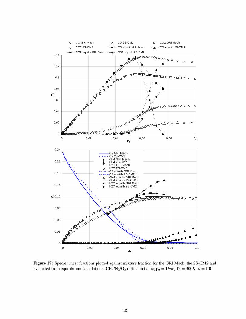
Figure 17 shows a good agreement between results obtained for the GRI Mech, the 2S-CM2 andequilibrium calculations, for the mixture fraction lower than a stoichiometric value of this quantity (zc <zst), thus for a fuel-lean side of the flame. Nevertheless, for zc > zst the difference, between thosecomputations, becomes significant. Higher temperatures, in comparison with equilibrium calculations,for a fuel-rich side of the flame, for both the GRI Mech and the 2S-CM2, were obtained (fig. 35). Thistemperature is called ”super-equilibrium temperature” and according to available literature [20, 15, 27],can be explained by differences in species diffusivities and heat transport, when detailed full transportspecies data is employed in calculations.
A maximum temperature in diffusion flames is an important quantity. In general, the maximumtemperature is obtained for stoichiometric value of the mixture fraction, where exothermic reactionsprogress relatively fast, in comparison to other regions of the flame. The maximum temperature isdecreasing with increasing the strain rate for higher values of this quantity (Figure 19). Further increaseof the strain rate could cause that the heat flux density, between the burned gases and the fresh mixture,is not sufficient to support the combustion process (quenching point).For lower strain rates (κ < (30− 50), the maximum temperature with stretch behaved incorrectly withtheory. This was probably the result of too narrow domain that was used in calculations, while the flamebecame wide, for a lower values of strain rate.
22

-0,8
-0,6
-0,4
-0,2
0
0,2
0,4
0,6
0,8
0 1 2 3 4 5 6 7 8 9 10
x, mm
u, m
/s
-1,0E+09
-8,0E+08
-6,0E+08
-4,0E+08
-2,0E+08
0,0E+00
Q, W
/m3
Velocity GRI Mech Velocity 2S-CM2Heat release GRI MechHeat release 2S-CM2
-0,8
-0,6
-0,4
-0,2
0
0,2
0,4
0,6
0,8
0 1 2 3 4 5 6 7 8 9 10
x, mm
u, m
/s
-1,0E+09
-8,0E+08
-6,0E+08
-4,0E+08
-2,0E+08
0,0E+00
Q, W
/m3
Velocity GRI Mech Velocity 2S-CM2Heat release GRI MechHeat release 2S-CM2
Figure 12: Velocity and heat release profiles comparison for the GRI Mech and the 2S-CM2; CH4/N2/O2diffusion flame; p0 = 1bar, T0 = 300K, κ = 100.
23

-900
-800
-700
-600
-500
-400
-300
-200
-100
0
0 50 100 150 200 250κ, 1/s
ΩC
H4,
mo
l/(m
2s)
GRI Mech
2S-CM2
Figure 13: Integrated fuel reaction rates plotted against strain rates for the GRI Mech and the 2S-CM2;CH4/N2/O2 diffusion flame; p0 = 1bar, T0 = 300K.
24

0
0,02
0,04
0,06
0,08
0 2 4 6 8 10x, mm
Xi
3,0E+02
8,0E+02
1,3E+03
1,8E+03
2,3E+03
T, K
CO GRI Mech CO 2S-CM2CO2 GRI MechCO2 2S-CM2Temperature GRI MechTemperature 2S-CM2
0
0,05
0,1
0,15
0,2
0 2 4 6 8 10x, mm
Xi
0
0,2
0,4
0,6
0,8
1
XC
H4
O2 GRI MechO2 2S-CM2H2O GRI MechH2O 2S-CM2CH4 GRI Mech CH4 2S-CM2
Figure 14: Species and temperature profiles for the GRI Mech and the 2S-CM2; CH4/N2/O2 diffusionflame; p0 = 1bar, T0 = 300K, κ = 100.
25

-1,5
-1
-0,5
0
0,5
1
1,5
0 2 4 6 8 10x, mm
u, m
/s
250
450
650
850
1050
1250
1450
1650
1850
2050
T, K
Velocity κ=50 Velocity κ=150 Velocity κ=250
Temperature κ=50 Temperature κ=150 Temperature κ=250
Figure 15: Profiles of the temperature and velocity for various stretch rates; GRI Mech; CH4/N2/O2diffusion flame; p0 = 1bar, T0 = 300K.
26

0
0,02
0,04
0,06
0,08
0,1
0,12
0,14
0 0,2 0,4 0,6 0,8 1zc
Yi
3,0E+02
8,0E+02
1,3E+03
1,8E+03
2,3E+03
T, K
CO GRI Mech CO 2S-CM2CO2 GRI MechCO2 2S-CM2Temperature GRI MechTemperature 2S-CM2
0
0,04
0,08
0,12
0,16
0,2
0,24
0 0,2 0,4 0,6 0,8 1zc
Yi
0
0,2
0,4
0,6
0,8
1
YC
H4
O2 2S-CM2H2O GRI MechH2O 2S-CM2O2 GRI MechCH4 GRI Mech CH4 2S-CM2
Figure 16: Species mass fractions and temperature plotted against mixture fraction for the GRI Mechand the 2S-CM2; CH4/N2/O2 diffusion flame; p0 = 1bar, T0 = 300K, κ = 100.
27
0
0,02
0,04
0,06
0,08
0,1
0,12
0,14
0 0,02 0,04 0,06 0,08 0,1zc
Yi
CO GRI Mech CO 2S-CM2 CO2 GRI Mech
CO2 2S-CM2 CO equilib GRI Mech CO equilib 2S-CM2
CO2 equilib GRI Mech CO2 equilib 2S-CM2
0
0,03
0,06
0,09
0,12
0,15
0,18
0,21
0,24
0 0,02 0,04 0,06 0,08 0,1zc
Yi
O2 GRI MechO2 2S-CM2CH4 GRI Mech CH4 2S-CM2H2O GRI MechH2O 2S-CM2O2 eqiulib GRI MechO2 equilib 2S-CM2CH4 equilib GRI MechCH4 equilib 2S-CM2H2O equilib GRI MechH2O equilib 2S-CM2
Figure 17: Species mass fractions plotted against mixture fraction for the GRI Mech, the 2S-CM2 andevaluated from equilibrium calculations; CH4/N2/O2 diffusion flame; p0 = 1bar, T0 = 300K, κ = 100.
28

1500
1600
1700
1800
1900
2000
2100
2200
2300
0 0,02 0,04 0,06 0,08 0,1 0,12 0,14zc
T, K
GRI Mech 2S-CM2Equilibrium 2S-CM2Equilibrium GRI Mech
Figure 18: Temperature plotted against mixture fraction for the GRI Mech, the 2S-CM2 and evaluatedfrom equilibrium calculations; CH4/N2/O2 diffusion flame; p0 = 1bar, T0 = 300K, κ = 100.
1900
1950
2000
2050
2100
2150
2200
2250
2300
0 50 100 150 200 250κ, 1/s
Tm
ax, K GRI Mech
2S-CM2
Figure 19: The comparison of the maximum temperature plotted against stretch rate for the GRI Mechand the 2S-CM2; CH4/N2/O2 diffusion flame; p0 = 1bar, T0 = 300K.
29

CH4/O2/CO2 FLAMES
Equilibrium computationsThe quantity used to measure the CO2 presence in the oxidizer is Xoxid
CO2, the mole fraction of carbon
dioxide in the oxidizer stream. It is 0 for pure oxygen and was changed up to 70% in this chapter.For higher temperatures, obtained during oxy-fuel conditions with oxygen-rich oxidizer, the differencebetween calculated adiabatic temperatures for various number of species is much greater than during theconventional combustion in air (Fig. 20). The higher adiabatic temperature difference occurs when lesscarbon dioxide is present in the oxidizer. The reason is that in higher temperatures oxidation reactionsproducts undergo dissociation and this requires energy. The smallest temperatures are obtained when all34 species are considered (Table 9). For the case with one-step mechanism, dissociation reactions do notexist, thus the temperature is too high (Fig. 20). The distinction between the adiabatic temperature of thecase with 34 species and with 4 species, for pure oxygen-methane flames, is as big as 2100K. Amongother reasons, this why the case with four species was not employed for further calculations.
Table 10: Number and kind of species for oxy-fuel combustion of methane
Number of Species listspecies
H2; H; O; O2; OH; H2O; HO2; H2O2;C; CH; CH2; CH2(s); CH3; CH4; CO;
34 CO2; HCO; CH2O; CH2OH; CH3O;CH3OH; C2H; C2H2; C2H3; C2H4;
C2H5; C2H6; HCCO; CH2CO; HCCOH;C3H7; C3H8; CH2CHO; CH3CHO
6 H2; O2; H2O; CH4; CO; CO25 O2; H2O; CH4; CO; CO24 O2; H2O; CH4; CO2
The underestimation of CO2 and over prediction of CO mole fraction for 5 species was found in theoxy-fuel case (Fig. 20). This tendency is intensified for greater mole fractions of molecular oxygen in theoxidizer, thus for larger temperatures. A quite good agreement was found in mole fractions of variousspecies, between the case with 6 and 34 species, in comparison to graphs plotted for less reactants.Nevertheless, the difference is still large especially for larger oxygen fraction in the oxidizer. Regardingthe work of Frassoldati et al. [3], at temperatures higher than 2500K not only H2 and CO have significantimpacts in limiting the temperature, but also radicals. This suggests that six species will not be enoughto describe properly the real flame for the higher oxygen mole fraction (> 50%) in the oxidizer.
30

0,00
0,20
0,40
0,60
0,80
0 20 40 60XCO2 in oxidizer, %
XC
O2
1600
2100
2600
3100
3600
4100
4600
5100
5600
Ta,
K
X; 34 speciesX; 6 speciesX; 5 speciesX, 4 speciesTemp; 34 speciesTemp; 6 speciesTemp; 5 speciesTemp, 4 species
0,00
0,05
0,10
0,15
0,20
0,25
0,30
0 20 40 60XCO2 in oxidizer, %
Xi
CO; 34 speciesCO; 6 speciesCO; 5 speciesH2; 34 speciesH2; 6 species
Figure 20: Burned mixture mole fractions and the adiabatic temperature plotted against mole fractionof CO2 in the oxidizer for CH4/CO2/O2 flame with different oxidation mechanisms for p0 = 1bar, T0 =300K, Φ = 1.
31

Auto-ignition delay timesAuto-ignition delay times for a mixture, which is composed of methane, molecular oxygen and carbondioxide are presented in Figure 22. For an oxy-fuel combustion as well as for a conventional combustionof methane in air (Fig. 5) a great disagreement was found between GRI Mech scheme and reducedmechanisms (J-L-JB and 2S-CM2-JB2), which only confirms the argument that low-number reactionschemes are not able to predict the ignition process. The divergence between results obtained for thedetailed mechanisms and reduced ones is larger for lower initial temperatures.Profiles of temperature and volumetric heat release for initial temperature equal to 1500K are plotted inFigure 21. A difference between different oxidation mechanisms can be seen clearly. The lowest timedelay at the same time with the most intensive heat release is achieved for a case with 2S-CM2-JB2mechanism. Obviously, the temperature for the detailed mechanism reaches the lowest level, what wasexplained in details in the chapter that deals with equilibrium calculations.
1400
1600
1800
2000
2200
2400
2600
2800
3000
0,001 0,01 0,1 1 10t, ms
T, K
-4,5E+15
-4,0E+15
-3,5E+15
-3,0E+15
-2,5E+15
-2,0E+15
-1,5E+15
-1,0E+15
-5,0E+14
0,0E+00
5,0E+14
1,0E+15
Q, W
/m3
Temperature GRI Mech Temperature J-L-JB Temperature 2S-CM2-JB2
Heat release GRI Mech Heat release J-L-JB Heat release 2S-CM2-JB2
Figure 21: Temperature and volumetric heat release profiles for CH4/CO2/O2 mixture, for CO2=61,5%mole fraction in the oxidizer, for different oxidations mechanisms, plotted against time; p0 = 1bar,Tinit=1500K, φ = 1.
32

1,0E-06
1,0E-05
1,0E-04
1,0E-03
1,0E-02
1,0E-01
1,0E+00
1,0E+01
1,0E+02
0,4 0,6 0,8 1 1,2 1,4
1000/T, 1/K
t, s
GRI Mech2S-CM2-JB2J-L-JB
1,0E-06
1,0E-05
1,0E-04
1,0E-03
1,0E-02
1,0E-01
1,0E+00
1,0E+01
1,0E+02
0,4 0,6 0,8 1 1,2 1,4
1000/T, 1/K
t, s
GRI Mech2S-CM2-JB2
J-L-JB
Figure 22: Auto-ignition delay times for CH4/CO2/O2 mixture, for CO2=61,5% (top graph) andCO2=72% (bottom graph) mole fraction in the oxidizer, for different oxidations mechanisms, plottedagainst reciprocal of the initial temperature multiplied by one thousand; p0 = 1bar, φ = 1.
33

One-dimensional premixed laminar flamesThe different diffusivity and thermal capacity of carbon dioxide and molecular nitrogen modify the com-bustion of CH4. According to the dependency of the laminar flame speed on the diffusion coefficient(Eq. (21)), lower thermal diffusivity in the CO2 atmosphere influences the laminar flame speed. Dif-ferent oxidizer compositions have effects on the chemistry itself. The dissociation of CO2 affects theproduction of carbon monoxide for higher temperatures (¿1300K) [14]. Nevertheless, a thermal effecton a laminar flame speed decrease was found as the major one by Benedetto et al. [2]. Carbon dioxidehas a higher specific heat capacity than N2, so that the flame has a much lower temperature compared toconventional combustion in air, for the same mole fraction of diluents in the oxidizer. Lower tempera-tures also have an impact on the combustion rate, which in conjunction with a lower thermal diffusivityand changes in chemistry cause a big difference in laminar flame speed values (Table 11).
Table 11: Summary of laminar flame speed values obtained during present work for methane oxidationsimulation in O2 = 21%/N2 = 79% and O2 = 21%/CO2 = 79% for various equivalence ratios, for detailedmechanism (in mm/s).
φ = 0,8 φ = 0,9 φ = 1,0 φ = 1,1N2/O2 0,263 0,326 0,365 0,370
CO2/O2 0,026 0,033 0,036 0,033
Calculations for different mole fractions of CO2 and O2 in the oxidizer were performed in order tofind the laminar flame speed which was obtained during a detailed chemistry simulation of a methanecombustion in the environment similar to air. Adiabatic flame temperature and laminar flame speedvariations with CO2 mole fractions in the oxidizer are presented in figure 23. The adiabatic temperatureand the laminar flame speed are inversely proportional to the CO2 mole fraction in the oxidizer. Agood agreement between present work and CH4 combustion simulation in Chemkin-Premix [2] can beobserved. For both adiabatic temperature and laminar flame speed, compatibility is much better forhigher mole fraction of oxygen in the oxidizer. For pure oxygen-methane flame the temperature reachesvalue at about 3050K and laminar flame speed is in the order of 3,1m/s.
For various equivalence ratio the laminar flame speed tendency is similar to that, which was obtainedfor N2/O2 case. However the maximum value is obtained for slightly fuel-lean conditions, especially forlower O2 dilution using CO2 (Fig. 24). General conclusion can be created, that the laminar flame speedis depended strongly on the oxygen concentration in the oxidizer.
Carbon dioxide mole fraction in the oxidizer, for which values of the laminar flame speed is approx-imately equal to the values obtained during combustion simulation in N2/O2 environment, is equal to0,615, for the equivalence ratio around one (Fig. 25). The further the mixture is from stoichiometricconditions the SL value disagree more. The adiabatic temperature is elevated for the CO2/O2 case atabout 250K roughly. Due to a flame stabilization, when an oxidizer is shifted from an air to a mixtureof CO2/O2, achieving similar laminar flame speeds for an oxy-fuel and a conventional combustion isimportant.
Figure 26 presents adiabatic temperature results for three different basic oxidation mechanisms de-scribed in this report (top graph). Adiabatic temperatures for the J-L mechanism and for the 2-stepmechanism are over predicted slightly, in comparison to results for the detailed mechanism. A signifi-cant disagreement within laminar flame speed is observed between the detailed mechanism and the J-Lor the 2S-CM2 mechanism (Figure 26 bottom graph). These reduced mechanisms were evaluated forfuel-air flames and this probably explains such a big divergence, when they are employed in oxy-fuelcombustion calculations. Likewise in the conventional combustion simulation with reduced mechanisms(Fig. 7), the oxy-fuel calculation of SL using the J-L mechanism preserves proper curve shape for dif-ferent equivalence ratios, as well for the 2S-CM2 mechanism laminar flame speed is overestimated forfuel-rich mixtures.
34

0
0,5
1
1,5
2
2,5
3
3,5
0 0,1 0,2 0,3 0,4 0,5 0,6 0,7 0,8XCO2oxid
SL, m
/s
1500
1700
1900
2100
2300
2500
2700
2900
3100
Ta,
K
Laminar flame speed - present workLaminar flame speed - [Benedetto]Adiabatic temperature - present workAdiabatic temperature - [Benedetto]
Figure 23: Laminar flame speed and adiabatic flame temperature plotted against CO2 mole fractionsin oxidizer. Results obtained by Benedetto et al. [2] (blank marks) and gained in present work duringsimulation of flame with GRI Mech (filled marks); p0 = 1bar, T0 = 300K, φ = 1,0.
0
0,5
1
1,5
2
2,5
3
0,5 0,7 0,9 1,1 1,3 1,5Φ
SL, m
/s
CO2=10%CO2=30%CO2=50%CO2=61,5%CO2=72%
Figure 24: Laminar flame speed for a variety of CO2 mole fraction in oxidizer plotted against equiva-lence ratio; p0 = 1bar, T0 = 300K, GRI Mech.
35

0,1
0,15
0,2
0,25
0,3
0,35
0,4
0,5 0,7 0,9 1,1 1,3 1,5Φ
SL, m
/s
1500
1700
1900
2100
2300
2500
2700
2900
Ta,
K
Sl CO2/O2Sl AirTa CO2/O2Ta Air
Figure 25: Laminar flame speed and adiabatic flame temperature plotted against equivalence ratio forconventional and for oxy-fuel combustion; p0 = 1bar, T0 = 300K, GRI Mech.
To improve the precision of reduced mechanisms, parameters from the Arrhenius equation (Eq. (13))were readjusted (Tables 5, 6). For the J-L mechanism two reactions have a major impact on the laminarflame speed: reactions 1 and 3 in Table 3. For both 2S-CM2-JB2 and J-L-JB mechanisms the agree-ment was improved considerably, however for a fuel-rich mixture the difference between the detailedmechanism and reduced ones is still relatively big, especially for the 2S-CM2-JB2 mechanism. The dif-ference is increasing with increasing equivalence ratio. When for the J-L-JB mechanism this differencecan be neglected, for the 2S-CM2-JB2 mechanism the pre-exponential factor adjustment has to be used(Eq. (15), Table 4) .
The similar flame speed for the conventional and the oxy-fuel combustion is not the only criterionconsidered in this work. Similar flame temperature profiles and gas concentration levels were acquiredby Andersson and Johnsson, during experiments, for 27% of molecular oxygen in the oxidizer [4]. Forthis reason, the simulation of methane combustion in the oxidizer mixture of O2=0,28/CO2=0,78 wasalso performed, in order to match the laminar flame profiles for the detailed mechanism and two reducedones.
The same procedure of calculations was carried out as for the case with 28% of oxygen in the oxi-dizer. A better agreement in values of the adiabatic temperature for the detailed mechanism and reducedones were obtained (Fig. 27) than for a case with 61,5% of CO2 in the oxidizer (Fig. 26). This wasobserved, because the lower temperature due to a lower oxygen concentration the lesser temperaturedivergence between different oxidation mechanisms. Values of the laminar flame speed, for reducedmechanism, were overestimated strongly in comparison to the GRI Mech calculations. To improve theconvergence and not to create new mechanisms, the same reduced schemes (J-L-JB and 2S-CM2-JB2)were used (Tables 5, 6). Nevertheless, after readjustment of Arrhenius parameters, a quite good agree-ment for SL could be observed, for various oxidation mechanisms during the combustion simulation offuel-lean and stoichiometric mixtures. Nevertheless, for fuel-rich mixtures, for 2S-CM2-JB2 mechanisma disagreement with the GRI Mech scheme was found, for that reason, a new 2-step scheme with PEAwas created (2S-CM2-JB3).
Figure 28 presents calculated values of SL for GRI Mech, 2S-CM2-JB2 and 2S-CM2-JB3 mecha-
36

1900
2000
2100
2200
2300
2400
2500
0,5 0,7 0,9 1,1 1,3 1,5Φ
Ta,
K
GRI Mech
J-L; J-L-JB
2S-CM2; 2S-CM2-JB2
0,1
0,2
0,3
0,4
0,5
0,6
0,7
0,8
0,5 0,7 0,9 1,1 1,3 1,5Φ
SL, m
/s
GRI MechJ-L2S-CM2J-L-JB2S-CM2-JB2
Figure 26: Comparison of the laminar flame speed and the adiabatic temperature results obtained forthe detailed mechanism, the original J-L mechanism, the original 2-step mechanism and readjusted ones(J-L-JB and 2S-CM2-JB2) for 38,5% of O2 in the oxidizer; p0 = 1bar, T0 = 300K.
37

1500
1600
1700
1800
1900
2000
2100
2200
0,5 0,7 0,9 1,1 1,3 1,5Φ
Ta,
K
GRI Mech
J-L; J-L-JB2S-CM2; 2S-CM2-JB2
0
0,05
0,1
0,15
0,2
0,25
0,3
0,35
0,5 0,7 0,9 1,1 1,3 1,5Φ
SL, m
/s
GRI MechJ-L2S-CM2J-L-JB2S-CM2-JB2
Figure 27: Comparison of the laminar flame speed and the adiabatic temperature results obtained forthe detailed mechanism, the original J-L mechanism, the original 2-step mechanism and readjusted ones(J-L-JB and 2S-CM2-JB2) for 28% of O2 in the oxidizer; p0 = 1bar, T0 = 300K.
38

0
0,1
0,2
0,3
0,4
0,5 0,7 0,9 1,1 1,3 1,5Φ
SL, m
/s
O2=28% 2S-CM2-JB2O2=28% 2S-CM2-JB3O2=38,5% 2S-CM2-JB2O2=38,5% 2S-CM2-JB3O2=28% GRI MechO2=38,5% GRI Mech
Figure 28: Results comparison of the laminar flame speed values computation for GRI Mech, 2S-CM2-JB2 and for2S-CM2-JB3 plotted against equivalence ratio; p0 = 1bar, T0 = 300K.
nisms. For oxidizer with 38,5% of oxygen a very good agreement between the GRI Mech and 2S-CM2-JB3 is achieved, after employing PEA, for a fuel-rich conditions.Taking into account the case with 28% of O2 in the oxidizer, the agreement is only sufficient due tothe fact, that PEA function as well as 2S-CM2-JB2 mechanism was created for the oxidizer containing38,5% of O2.
39
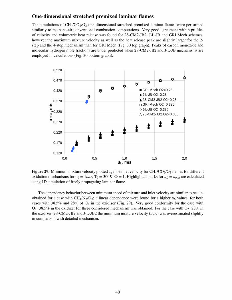
One-dimensional stretched premixed laminar flamesThe simulations of CH4/CO2/O2 one-dimensional stretched premixed laminar flames were performedsimilarly to methane-air conventional combustion computations. Very good agreement within profilesof velocity and volumetric heat release was found for 2S-CM2-JB2, J-L-JB and GRI Mech schemes,however the maximum mixture velocity as well as the heat release peak are slightly larger for the 2-step and the 4-step mechanism than for GRI Mech (Fig. 30 top graph). Peaks of carbon monoxide andmolecular hydrogen mole fractions are under predicted when 2S-CM2-JB2 and J-L-JB mechanisms areemployed in calculations (Fig. 30 bottom graph).
0,120
0,170
0,220
0,270
0,320
0,370
0,420
0,470
0,520
0,0 0,5 1,0 1,5 2,0uL, m/s
um
in, m
/s
GRI Mech O2=0,28J-L-JB O2=0,282S-CM2-JB2 O2=0,28GRI Mech O2=0,385J-L-JB O2=0,3852S-CM2-JB2 O2=0,385
Figure 29: Minimum mixture velocity plotted against inlet velocity for CH4/CO2/O2 flames for differentoxidation mechanisms for p0 = 1bar, T0 = 300K, Φ = 1; Highlighted marks for uL = umin are calculatedusing 1D simulation of freely propagating laminar flame.
The dependency behavior between minimum speed of mixture and inlet velocity are similar to resultsobtained for a case with CH4/N2/O2; a linear dependence were found for a higher uL values, for bothcases with 38,5% and 28% of O2 in the oxidizer (Fig. 29). Very good conformity for the case withO2=38,5% in the oxidizer for three considered mechanism was obtained. For the case with O2=28% inthe oxidizer, 2S-CM2-JB2 and J-L-JB2 the minimum mixture velocity (umin) was overestimated slightlyin comparison with detailed mechanism.
40

0
0,5
1
1,5
2
2,5
3
0 1 2 3 4 5 6 7 8 9 10
x, mm
u, m
/s
3,0E+02
8,0E+02
1,3E+03
1,8E+03
2,3E+03
T, K
Velocity GRI Mech Velocity J-L-JBVelocity 2S-CM2-JB2Temperature GRI MechTemperature J-L-JBTemperature 2S-CM2-JB2
0
0,02
0,04
0,06
0,08
0,1
0,12
0 1 2 3 4 5 6 7 8 9 10
x, mm
Xi
-1,0E+10
-8,0E+09
-6,0E+09
-4,0E+09
-2,0E+09
0,0E+00
Q, W
/m3
CO GRI Mech CO J-L-JBCO 2S-CM2-JB2H2 GRI MechH2 J-L-JBHeat release GRI MechHeat release J-L-JBHeat release 2S-CM2-JB2
Figure 30: Species, temperature, velocity and heat release profiles for CH4/CO2/O2 flames for differentoxidation mechanisms for p0 = 1bar, T0 = 300K, Φ = 1, uL = 1m/s, Xoxid
CO2= 0,615.
41

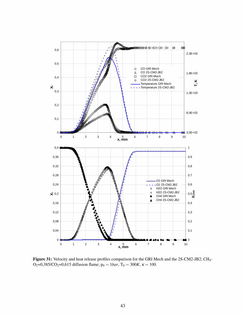
One-dimensional stretched diffusion laminar flamesSimulations of CH4/CO2/O2 one-dimensional stretched diffusion laminar flames were performed simi-larly to methane-air conventional combustion computations for the GRI Mech and the 2S-CM2. Resultsin this chapter are presented for CO2 in the oxidizer equal to 0,615.Very good agreement within profiles of CH4, O2, H2O mole fractions and velocity was found for 2S-CM2-JB2 and GRI Mech schemes, for a strain rate κ = 100 (Fig. 31 32). Nevertheless, the difference intemperature, heat release, fuel destruction rate and mole fractions of carbon dioxide and carbon monox-ide was noticed, as it was observed for methane-air diffusion flames.
The definition of the mixture fraction, because of the oxidizer composition (CO2/O2), could notbe defined in simple way using atoms of carbon, therefore, the theoretical definition was employedin postprocessing of outcomes (Equation (8)). The mixture fraction plotted against coordinates showsthe disturbance of the tendency at the area, where the reactions proceed with the highest intensity (forzst ≈ 0,073), especially for the detailed mechanism simulation (Fig. 32 bottom graph).
Similar conclusion can be drawn, as for a conventional combustion case, that absolute value of theintegrated fuel reaction rate is increasing with increasing strain rate (Figure 33). For very low strainrates, the difference between values of this quantity, for the GRI Mech scheme and the 2S-CM2-JB2mechanism, becomes negligible.
A good agreement between results obtained for the GRI Mech, the 2S-CM2-JB2 and equilibriumcalculations was found, for the mixture fraction lower than stoichiometric value of this quantity (Figure34). Nevertheless, for zc > zst the difference, between results obtained for different calculations, becomessignificant, especially for mass fraction of carbon dioxide. Higher temperatures, in comparison withequilibrium calculations, were obtained only for the 2S-CM2-JB2 scheme for wide range of mixturefraction values (Fig. 35). The temperature difference between calculation using the GRI Mech and the2S-CM2-JB2 reached value 250K approximately.
In general, the decrease of the maximum temperatures with increase of stretch rate was found forthe GRI Mech, while the maximum temperature obtained for the 2S-CM2-JB2 mechanism was found tobe almost insensitive on the strain rate (Figure 36). For the case where oxidizer contained 28% of theO2, the quenching point were found for strain rate surpassing value of 1901/s, for detailed mechanismcalculations.
42
0
0,1
0,2
0,3
0,4
0,5
0,6
0 1 2 3 4 5 6 7 8 9 10x, mm
Xi
3,0E+02
8,0E+02
1,3E+03
1,8E+03
2,3E+03
T, K
CO GRI Mech CO 2S-CM2-JB2CO2 GRI MechCO2 2S-CM2-JB2Temperature GRI MechTemperature 2S-CM2-JB2
0
0,04
0,08
0,12
0,16
0,2
0,24
0,28
0,32
0,36
0,4
0 1 2 3 4 5 6 7 8 9 10x, mm
Xi
0
0,1
0,2
0,3
0,4
0,5
0,6
0,7
0,8
0,9
1
XC
H4
O2 GRI MechO2 2S-CM2-JB2H2O GRI MechH2O 2S-CM2-JB2CH4 GRI Mech CH4 2S-CM2-JB2
Figure 31: Velocity and heat release profiles comparison for the GRI Mech and the 2S-CM2-JB2; CH4-O2=0,385/CO2=0,615 diffusion flame; p0 = 1bar, T0 = 300K, κ = 100.
43

-0,6
-0,4
-0,2
0
0,2
0,4
0 1 2 3 4 5 6 7 8 9 10
x, mm
u, m
/s
-9,0E+08
-7,0E+08
-5,0E+08
-3,0E+08
-1,0E+08
1,0E+08
Q, W
/m3
Velocity GRI Mech Velocity 2S-CM2-JB2Heat release GRI MechHeat release 2S-CM2-JB2
-2400
-1900
-1400
-900
-400
0 1 2 3 4 5 6 7 8 9 10x, mm
wC
H4,
mo
l/(m
3 s)
0
0,2
0,4
0,6
0,8
1
zwCH4 GRI MechwCH4 2S-CM2-JB2z GRI Mechz 2S-CM2-JB2
Figure 32: Velocity, heat release, fuel destruction rate and mixture fraction profiles comparison for theGRI Mech and the 2S-CM2-JB2; CH4-O2=0,385/CO2=0,615 diffusion flame; p0 = 1bar, T0 = 300K,κ = 100.
44

-1400
-1200
-1000
-800
-600
-400
-200
0
0 50 100 150 200 250κ, 1/s
ΩC
H4,
mo
l/(m
2 s) GRI Mech
2S-CM2-JB2
Figure 33: Integrated fuel reaction rates plotted against strain rates for the GRI Mech and the 2S-CM2-JB2; CH4-O2=0,385/CO2=0,615 diffusion flame; p0 = 1bar, T0 = 300K.
45

0
0,05
0,1
0,15
0,2
0,25
0,3
0 0,02 0,04 0,06 0,08 0,1 0,12z
Yi
0
0,2
0,4
0,6
0,8
1
YC
O2
CO GRI Mech CO 2S-CM2 CO equilib GRI Mech
CO equilib 2S-CM2 CO2 GRI Mech CO2 2S-CM2
CO2 equilib GRI Mech CO2 equilib 2S-CM2
0
0,04
0,08
0,12
0,16
0,2
0,24
0,28
0,32
0 0,02 0,04 0,06 0,08 0,1 0,12z
Yi
O2 GRI MechO2 2S-CM2CH4 GRI Mech CH4 2S-CM2H2O GRI MechH2O 2S-CM2O2 eqiulib GRI MechO2 equilib 2S-CM2CH4 equilib GRI MechCH4 equilib 2S-CM2H2O equilib GRI MechH2O equilib 2S-CM2
Figure 34: Species mass fractions plotted against mixture fraction for the GRI Mech, the 2S-CM2-JB2and evaluated from equilibrium calculations; CH4-O2=0,385/CO2=0,615 diffusion flame; p0 = 1bar,T0 = 300K, κ = 100.
46

1500
1700
1900
2100
2300
2500
0 0,02 0,04 0,06 0,08 0,1 0,12 0,14z
T, K
GRI Mech2S-CM2-JB2Equilibrium 2S-CM2-JB2Equilibrium GRI Mech
Figure 35: Temperature plotted against mixture fraction for the GRI Mech, the 2S-CM2-JB2 and evalu-ated from equilibrium calculations; CH4-O2=0,385/CO2=0,615 diffusion flame; p0 = 1bar, T0 = 300K,κ = 100.
2100
2150
2200
2250
2300
2350
2400
2450
2500
2550
2600
0 50 100 150 200 250 300κ, 1/s
Tm
ax, K GRI Mech
2S-CM2-JB2
Figure 36: The comparison of the maximum temperature plotted against stretch rate for the GRI Mechand the 2S-CM2-JB2; CH4-O2=0,385/CO2=0,615 diffusion flame; p0 = 1bar, T0 = 300K.
47

CONCLUSIONSTwo reduced mechanisms (2S-CM2 and J-L) have been tested for a conventional air-methane combus-tion. Whereas, existing (2S-CM2 and J-L) schemes and refined ones (2S-CM2-JB2 and J-L-JB) wereverified using detailed chemistry computations, for specified oxy-fuel conditions.
Results for the air-methane case, obtained for the J-L scheme and for GRI Mech, are in generalin better agreement than those evaluated for the 2S-CM2. However, the laminar flame speed obtainedfor the 2S-CM2 scheme agreed more with results for the GRI Mech than the J-L mechanism, especiallywhen at the rich side of the flame, for the 2-step scheme, a pre-exponential factor adjustment is employed(2S-CM2-JB1). Auto-ignition delay times obtained for both the J-L as well as for the 2S-CM2 are signif-icantly shorter than this quantity obtained for the GRI Mech, thus can be concluded that highly reducedschemes are not able to predict this parameter. The equilibrium calculations have shown that because ofconsiderable overestimation of the adiabatic temperatures for the one-step scheme, this mechanism can-not be used with success in modeling of real processes. Diffusion flames for a conventional methane-aircombustion show a good agreement between detailed mechanism calculations and the 2S-CM2 schemefor some of the major species excluding CO2 and CO.
A large disagreement between detailed chemistry calculations, using the GRI Mech, and resultsobtained for J-L and 2S-CM2 global schemes, for the oxy-fuel combustion, was found for freely propa-gating 1D laminar premixed flames. Therefore, two new major schemes were evaluated (2S-CM2-JB2and J-L-JB). Verification of new schemes was performed in order to obtain similar values of laminarflame speeds for air-methane computations, what were achieved for CO2 mole fraction in the oxidizerequal to 0,615. However, the usefulness of those schemes were also tested for CO2 mole fraction inthe oxidizer, which insures similar thermal conditions to those, which are present during combustion ofmethane in air. The prediction of laminar flame speeds were improved significantly, when new schemesfor the oxy-methane combustion were employed in simulations.Similarly, to the air-methane case, the ignition delay times could not be predicted correctly by the 2S-CM2-JB2 scheme as well as by the J-L-JB mechanism. The prediction of the minimum velocity, whichwas an important quantity for premixed stretched laminar flames, was in very good agreement, for twodifferent oxidizer compositions, at near stoichiometric conditions. A sufficient agreement was also foundfor diffusion flames, for the GRI Mech mechanism and the 2S-CM2-JB2 scheme, especially for fuel-leanside of the flame.
Generally, modified schemes improved the agreement with the detailed mechanism considerably, forboth considering compositions of the oxidizer.
48

ACKNOWLEDGMENTSThe work presented in this report has been performed at CERFACS (The European Center for Researchand Advanced Training in Scientific Computation) and at IMFT (Institut de Mecanique des Fluidesde Toulouse) in Toulouse in France. The research activity was supported by the Marie Curie HostFellowships for Early Stage Research Training within the framework of the ECComET (Efficient andClean Combustion Experts Training).I would like to thank my supervisor Professor Thierry Poinsot for his continuous support and helpfulsuggestions during my training. I also would like to thank my second supervisor Laurent Selle for hishelp.I must mention Benedetta Franzelli, who gave me apposite suggestions regarding my calculations.Finally, I would like to thank to all who gave me any help concerning my work.
49

References[1] Cosilab combustion simulation laboratory manual, version 2.0.[2] E. Salzano F. Cammarota G. Russo A. Di Benedetto, V. Di Sarli, Explosion behavior of
ch4/o2/n2/co2 and h2/o2/n2/co2 mixtures, International Journal of Hydrogen Energy 34 (2009),6970 6978.
[3] T. Faravelli E. Ranzi C. Candusso A. Frassoldati, A. Cuoci and D. Tolazzi, Simplified kineticschemes for oxy-fuel combustion, 1st International Conference on Sustainable Fossil Fuels for Fu-ture Energy, 2009.
[4] K. Andersson and Filip Johnsson, Flame and radiation characteristics of gas-fired o2/co2 combus-tion, Fuel 86 (2007), 656668.
[5] C. K. Law B. H. Chao, F. N. Egolfopoulos, Structure and propagation of premixed flame in nozzle-generated counterflow, Combustion and Flame 109 (1997), 620–638.
[6] G. Boudier, Methane/air flame with 2-step chemistry: 2s ch4 cm2, Tech. report, CERFACS, 2007.[7] I. Gokalp D. F. Kurtulus C. Cohea, Ch. Chauveau, Co2 addition and pressure effects on laminar
and turbulent lean premixed ch4 air flames, Proceedings of the Combustion Institute 32 (2009),18031810.
[8] C. K. Law C. J. Sung and J. Y. Chen, An augmented reduced mechanism for methane oxidationwith comprehensive global parametric validation, Twenty-Seventh Symposium (International) onCombustion/The Combustion Institute, 1998.
[9] James F. Driscoll, Turbulent premixed combustion: Flamelet structure and its effect on turbulentburning velocities, Progress in Energy and Combustion Science 34 (2008), 91134.
[10] M. Frenklach N. W. Moriarty B. Eiteneer M. Goldenberg C. T. Bowman R. K. Hanson S. SongW. C. Gardiner Jr. V. V. Lissianski G. P. Smith, D. M. Golden and Z. Qin, Gri mech 3.0http://www.me.berkeley.edu/gri-mech/.
[11] L.Y.M. Gicquel, How to introduce new fuels in avbp.[12] X. J. Gu, M. Z. Haq, M. Lawes, and R. Woolley, Laminar burning velocity and markstein lengths
of methane-air mixtures, Combust. Flame 121 (2000), 41–58.[13] J.P. Holman, Thermodynamics 3rd edition, McGraw-Hill, 1980.[14] T. Giselsson J. Andersen, Ch. L. Rasmussen and P. Glarborg, Global combustion mechanisms for
use in cfd modeling under oxy-fuel conditions, Energy & Fuels 23 (2009), 13791389.[15] O. B. Kwon E. J. Lee J. H. Yun J. S. Kim, J. Park and S. I. Keel, Preferential diffusion effects in
opposed-flow diffusion flame with blended fuels of ch4 and h2, International Journal of HydrogenEnergy 33 (2008), 842 850.
[16] W. P. Jones and R. P. Lindstedt, Global reaction schemes for hydrocarbon combustion, Combust.Flame 73 (1988), 222–233.
[17] Andrzej Kowalewicz, Podstawy procesow spalania, Wydawnictwa Naukowo-Techniczne, 2000.[18] T. Boushaki B. Ferret L. Selle, Y. Dhue and T. Poinsot, Experimental and numerical study of
the accuracy of flame-speed measurements in bunsen burner, Sixth Mediterranean CombustionSymposium MCS 6, 2009.
[19] G. Lacaze, Arrhenius kinetic parameters for a reversed equilibrium reaction, Tech. report, CER-FACS, 2006.
[20] D. Thevenin O. Gicquel and N. Darabiha, Influence of differential diffusion on super-equilibriumtemperature in turbulent non-premixed hydrogen/air flames, Flow, Turbulence and Combustion 73(2004), 307321.
[21] Ryszard Petela, Paliwa i ich spalanie cz. ii spalanie, Dzial Wydawnictw Politechniki Slaskiej,1982.
[22] N. Peters and R. J. Kee, The computation of stretched laminar methane-air diffusion flames usinga reduced four-step mechanism, Combustion and Flame 68 (1987), 17–29.
[23] T. Poinsot and D. Veynante, Theoretical and numerical combustion, R.T. Edwards, 2nd edition,2005.
50

[24] B. Rogg R. S. Cant and K. N. C. Bray, On laminar flamelet modelling of the mean reaction rate ina premixed turbulent flame, Combustion Science and Technology 69 (1990), 53–61.
[25] J. Quinard S. G. Davis and G. Searby, Determination of markstein numbers in counterflow pre-mixed flames, Combustion and Flame 130 (2002), 112–122.
[26] J. Szargut, Termodynamika techniczna dla kierunkow nieenergetycznych, Wydawnictwo Politech-niki Slaskiej, 1969.
[27] Z. Xu T. Takagi and M. Komiyama, Preferential diffusion effects on the temperature in usual andinverse diffusion flames, Combustion and flame 106 (1996), 252–260.
[28] J. Tomeczek, Spalanie i plomienie gazowe, Dzial Wydawnictw Politechniki Slaskiej, 1982.[29] C. M. Vagelopoulos and F. Egolfopoulos, Direct experimental determination of laminar flame
speeds, 27th Symp. (Int.) on Combustion, The Combustion Institute, Pittsburgh, 1998, pp. 513–519.
[30] C. Westbrook and F. Dryer, Simplified reaction mechanism for the oxidation of hydrocarbon fuelsin flames, Combust. Sci. Tech. 27 (1981), 31–43.
[31] A. C. Zambon and H. K. Chelliah, Explicit reduced reaction models for ignition, flame propagation,and extinction of c2h4/ch4/h2 and air systems, Combustion and Flame 150 (2007), 71–91.
51