redington wind farm project erosion and sedimentation ......redington wind farm project page 1...
TRANSCRIPT

Redington Wind Farm Project
Erosion and Sedimentation Control Plan for Transmission Line Corridor Construction
Prepared by:
DeLuca-Hoffman Associates, Inc.
South Portland, Maine

Redington Wind Farm Project Page i
Erosion and Sedimentation Control Plan for Transmission Line Corridor Construction
Table of Contents
1.0 Introduction ........................................................................................................................ 1 2.0 Existing Site Conditions..................................................................................................... 4 3.0 Overview of Soil Erosion and Sedimentation Concerns .................................................... 6 4.0 Construction Activities and Procedures ............................................................................. 8
4.1 Transmission Line .............................................................................................................. 8 4.2 Substation Interconnect .................................................................................................... 11
5.0 Erosion and Sedimentation Control Plan Guiding Principles .......................................... 12 5.1 Timing of Work................................................................................................................ 13 5.2 Minimize Disturbed Areas ............................................................................................... 16 5.3 The Proper Selection and Installation of Erosion Control Materials................................ 17 5.4 The Availability of the Materials for Construction .......................................................... 17
6.0 Proposed Erosion/Sedimentation Control Measures ........................................................ 18 6.1 Siltation Fence.................................................................................................................. 19 6.2 Mulch ............................................................................................................................... 20 6.3 Wood Waste ..................................................................................................................... 20 6.4 Construction Entrances..................................................................................................... 21 6.5 Dirtbags™ ........................................................................................................................ 21 6.6 Loam and Seed ................................................................................................................. 21
7.0 Temporary Erosion/Sedimentation Control Measures ..................................................... 21 8.0 Standards for Stabilizing Sites for the Winter .................................................................. 24
8.1 Standard For The Timely Stabilization Of Ditches And Channels .................................. 24 8.2 Standard For The Timely Stabilization Of Disturbed Slopes........................................... 25 8.3 Standard For The Timely Stabilization Of Disturbed Soil ............................................... 26
9.0 Sedimentation Sumps ....................................................................................................... 28 10.0 Permanent Erosion Control Measures .............................................................................. 28 11.0 Erosion and Sedimentation Control Implementation Process .......................................... 28 12.0 Contracting Procedure...................................................................................................... 29
12.1 The Work Shall Be Constructed In Accordance With This Erosion Control Plan........... 30 12.2 The Area of Denuded Non-Stabilized Construction Shall Be Limited To The Minimum
Area Practicable ............................................................................................................... 30 13.0 Provisions for Winter or Seasonal Shutdown................................................................... 31 14.0 Provisions for Maintenance of the Erosion/Sedimentation Control Features .................. 31 15.0 Preconstruction Conference ............................................................................................. 34 16.0 Closure ............................................................................................................................. 34
Redington Wind Farm Project Page ii
Erosion and Sedimentation Control Plan for Transmission Line Corridor Construction
List of Appendices Appendix A - Seeding Plan
Appendix B - Sample Certification and Inspection Forms
Appendix C – Erosion Control Specifications
Appendix D – Figure T-1

Redington Wind Farm Project Page iii
Erosion and Sedimentation Control Plan for Transmission Line Corridor Construction
List of Tables
Table 1 - Surficial Soil Types and Relative Erodibility Table 2 – Summary of Transmission Line Corridor Construction Lengths Table 3 - Schedule of Silt Fence Requirements

Redington Wind Farm Project Page 1
Erosion and Sedimentation Control Plan for Transmission Line Corridor Construction
1.0 Introduction DeLuca-Hoffman Associates, Inc. has prepared the following plan, which
presents the erosion and sedimentation control provisions required to construct
the transmission line corridors. Redington Mountain Windpower, LLC has
retained DeLuca-Hoffman Associates, Inc. to prepare a number of reports for the
Redington Wind Farm Project. The work of DeLuca-Hoffman Associates, Inc. is
summarized in seven reports, which accompany the Maine Department of
Environmental Protection (MeDEP) and LURC applications and are titled:
Erosion and Sedimentation Control Plan for Roadway Construction; Basis of Design for the Roadways to Access Wind Turbines;
Basis of Stormwater Management for Access Roadways;
Access Road Maintenance;
Blasting;
Erosion and Sedimentation Control Plan for Transmission Line Corridor
Construction; and Solid Waste
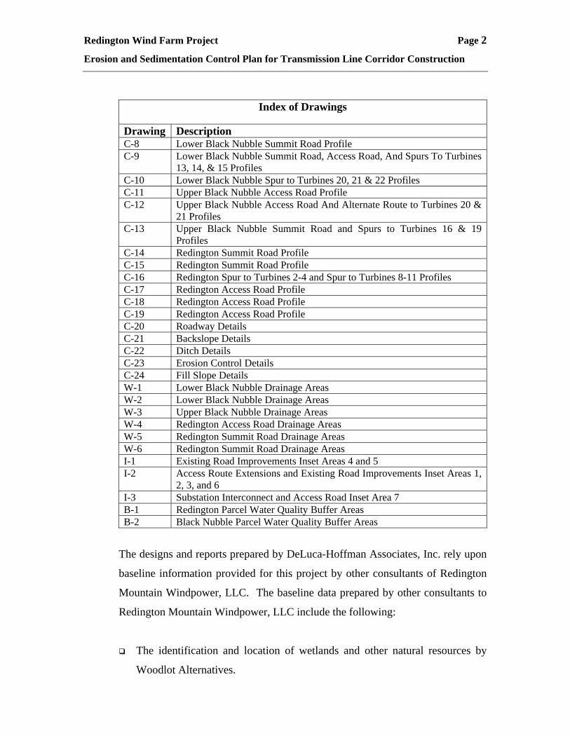
The reports are supported by a series of drawings prepared by DeLuca-Hoffman
Associates, Inc. and include the following:
Index of Drawings
Drawing Description Base Map Redington Wind Farm Project Base Map C-1 Cover Sheet, Index And Legend C-2 Lower Black Nubble Summit Road C-3 Lower Black Nubble Access Road, Spur To Turbines 20, 21 & 22, and
Portions of Summit Roads C-4 Upper Black Nubble Access Road And Summit Road C-5 Redington Access Road C-6 Redington Summit Road And Spurs To Turbines 1, 2, 3 & 4 C-7 Redington Summit Road And Spur to Turbines 8, 9, 10 & 11
Redington Wind Farm Project Page 2
Erosion and Sedimentation Control Plan for Transmission Line Corridor Construction
Index of Drawings
Drawing Description C-8 Lower Black Nubble Summit Road Profile C-9 Lower Black Nubble Summit Road, Access Road, And Spurs To Turbines
13, 14, & 15 Profiles C-10 Lower Black Nubble Spur to Turbines 20, 21 & 22 Profiles C-11 Upper Black Nubble Access Road Profile C-12 Upper Black Nubble Access Road And Alternate Route to Turbines 20 &
21 Profiles C-13 Upper Black Nubble Summit Road and Spurs to Turbines 16 & 19
Profiles C-14 Redington Summit Road Profile C-15 Redington Summit Road Profile C-16 Redington Spur to Turbines 2-4 and Spur to Turbines 8-11 Profiles C-17 Redington Access Road Profile C-18 Redington Access Road Profile C-19 Redington Access Road Profile C-20 Roadway Details C-21 Backslope Details C-22 Ditch Details C-23 Erosion Control Details C-24 Fill Slope Details W-1 Lower Black Nubble Drainage Areas W-2 Lower Black Nubble Drainage Areas W-3 Upper Black Nubble Drainage Areas W-4 Redington Access Road Drainage Areas W-5 Redington Summit Road Drainage Areas W-6 Redington Summit Road Drainage Areas I-1 Existing Road Improvements Inset Areas 4 and 5 I-2 Access Route Extensions and Existing Road Improvements Inset Areas 1,
2, 3, and 6 I-3 Substation Interconnect and Access Road Inset Area 7 B-1 Redington Parcel Water Quality Buffer Areas B-2 Black Nubble Parcel Water Quality Buffer Areas
The designs and reports prepared by DeLuca-Hoffman Associates, Inc. rely upon
baseline information provided for this project by other consultants of Redington
Mountain Windpower, LLC. The baseline data prepared by other consultants to
Redington Mountain Windpower, LLC include the following:
The identification and location of wetlands and other natural resources by
Woodlot Alternatives.

Redington Wind Farm Project Page 3
Erosion and Sedimentation Control Plan for Transmission Line Corridor Construction
Surficial Soils Surveys and narratives prepared by Al Frick.
Base topographic mapping prepared by Aerial Survey.
Geotechnical evaluations and recommendations for Roadway Construction
prepared by S. W. Cole.
There are other physical elements of the project such as the staging area, small
buildings, and the wind turbines, with attendant construction areas, which are
being designed by other consultants and discussed in separate portions of the
application.
This plan presents the erosion and sedimentation control provisions required to
construct the transmission line corridors. There is the potential for conditions to
be encountered during construction that have not been anticipated at this time,
which will require modification to this plan. This plan identifies the tools which
can be implemented during construction of the transmission line corridors,
explains the basis for their use, and provides details for their installation. The
erosion and sedimentation control plan and attendant drawings are not intended to
provide the exact location for placement of the erosion control measures, but
rather provide the basis for their use. The erosion and sedimentation control plan
has been developed to satisfy the requirements of LURC Chapter 10 Rules and
Standards and the MeDEP, and calls for provisions for the construction of
transmission line corridors to minimize unreasonable soil erosion and not result in
reduction in the capacity of the land to absorb and hold water.
This plan only covers the installation of the transmission lines and poles. The
construction of any road extensions to access the transmission line corridors is not
discussed in this section because that activity will be required to follow the
erosion & sedimentation control plan developed for the roads to access the wind
turbine sites. Permanent roads along the transmission line corridors are not
proposed as part of this project.

Redington Wind Farm Project Page 4
Erosion and Sedimentation Control Plan for Transmission Line Corridor Construction
The construction of the transmission lines for the Redington Wind Farm Project
will disturb areas limited to those in immediate vicinity of pole and guy
installations and as necessary to level rough terrain to allow passage of tracked
equipment along the corridors. Table 1 below presents a summary of
approximate transmission line corridor construction lengths for the project.
Table 1 – Summary of Transmission Line Corridor Construction LengthsTransmission Line Corridor Segment Miles
Redington 34.5kV transmission line (Red Line) 2.6
Black Nubble 34.5kV transmission line (Black Line) 1.2
115kV transmission line (Main Line) 7.5
TOTAL Approx. 11.3 Miles
2.0 Existing Site Conditions The proposed wind turbines will be erected on two mountaintop ranges:
Redington Range and Black Nubble Range. 34.5kV transmission lines are
proposed to transmit the power generated by the turbines from each mountain
range to the substation interconnect (see project Base Map for location). A
115kV transmission line is proposed to transmit the power from the substation to
the CMP substation located just off Route 27 on the northern boundary of
Carrabassett Valley. The 34.5kV transmission lines will require a cleared Right-
of-Way (ROW) width of 75 feet, the 115kV transmission line will require a 150
foot wide cleared ROW. The topography along the proposed transmission line
corridors varies from quite steep in the higher elevations to relatively mild in the
lower valleys with slopes ranging between 40% and 5%.
The proposed transmission line corridor from Redington Mountain to the
substation (the Red Line shown on the Base Map) is approximately 2.6 miles
long and follows a similar route to that of RE6b as the corridor approaches the
substation interconnect. The existing woods road along the route of RE6b will be
utilized to access the transmission line corridor from Redington Mountain.
Redington Wind Farm Project Page 5
Erosion and Sedimentation Control Plan for Transmission Line Corridor Construction
The proposed transmission line corridor from Black Nubble Mountain to the
substation (the Black Line shown on the Base Map) is approximately 1.2 miles
long and will be accessed from the existing woods road along Nash Stream and
from an existing logging road off RE2 near C6 shown on the Base Map.
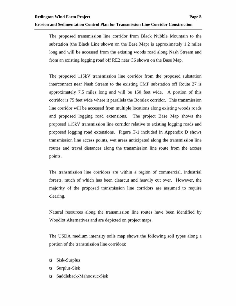
The proposed 115kV transmission line corridor from the proposed substation
interconnect near Nash Stream to the existing CMP substation off Route 27 is
approximately 7.5 miles long and will be 150 feet wide. A portion of this
corridor is 75 feet wide where it parallels the Boralex corridor. This transmission
line corridor will be accessed from multiple locations along existing woods roads
and proposed logging road extensions. The project Base Map shows the
proposed 115kV transmission line corridor relative to existing logging roads and
proposed logging road extensions. Figure T-1 included in Appendix D shows
transmission line access points, wet areas anticipated along the transmission line
routes and travel distances along the transmission line route from the access
points.
The transmission line corridors are within a region of commercial, industrial
forests, much of which has been clearcut and heavily cut over. However, the
majority of the proposed transmission line corridors are assumed to require
clearing.
Natural resources along the transmission line routes have been identified by
Woodlot Alternatives and are depicted on project maps.
The USDA medium intensity soils map shows the following soil types along a
portion of the transmission line corridors:
Sisk-Surplus
Surplus-Sisk
Saddleback-Mahoosuc-Sisk
Redington Wind Farm Project Page 6
Erosion and Sedimentation Control Plan for Transmission Line Corridor Construction
Ricker-Rock Outcrop
Telos Chesuncook
Colton Sheepscot
Dixfield Marlow
Colonel Dixfield
These soils are described in the detailed soils narrative prepared by Al Frick.
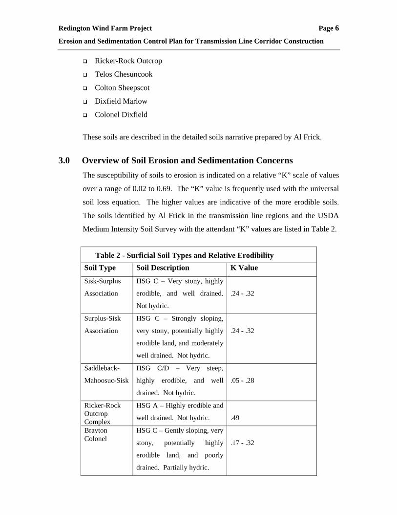
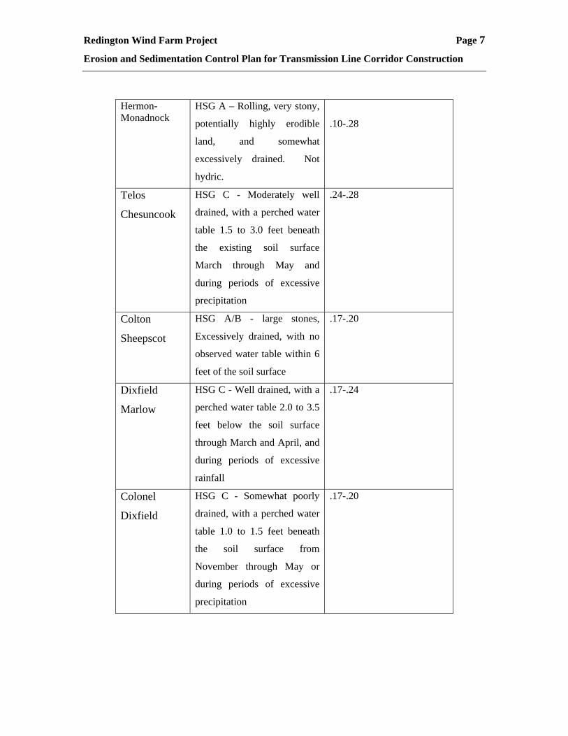
3.0 Overview of Soil Erosion and Sedimentation Concerns
The susceptibility of soils to erosion is indicated on a relative “K” scale of values
over a range of 0.02 to 0.69. The “K” value is frequently used with the universal
soil loss equation. The higher values are indicative of the more erodible soils.
The soils identified by Al Frick in the transmission line regions and the USDA
Medium Intensity Soil Survey with the attendant “K” values are listed in Table 2.
Table 2 - Surficial Soil Types and Relative Erodibility Soil Type Soil Description K Value
Sisk-Surplus
Association
HSG C – Very stony, highly
erodible, and well drained.
Not hydric.
.24 - .32
Surplus-Sisk
Association
HSG C – Strongly sloping,
very stony, potentially highly
erodible land, and moderately
well drained. Not hydric.
.24 - .32
Saddleback-
Mahoosuc-Sisk
HSG C/D – Very steep,
highly erodible, and well
drained. Not hydric.
.05 - .28
Ricker-Rock Outcrop Complex
HSG A – Highly erodible and
well drained. Not hydric.
.49
Brayton Colonel
HSG C – Gently sloping, very
stony, potentially highly
erodible land, and poorly
drained. Partially hydric.
.17 - .32
Redington Wind Farm Project Page 7
Erosion and Sedimentation Control Plan for Transmission Line Corridor Construction
Hermon-Monadnock
HSG A – Rolling, very stony,
potentially highly erodible
land, and somewhat
excessively drained. Not
hydric.
.10-.28
Telos
Chesuncook
HSG C - Moderately well
drained, with a perched water
table 1.5 to 3.0 feet beneath
the existing soil surface
March through May and
during periods of excessive
precipitation
.24-.28
Colton
Sheepscot
HSG A/B - large stones,
Excessively drained, with no
observed water table within 6
feet of the soil surface
.17-.20
Dixfield
Marlow
HSG C - Well drained, with a
perched water table 2.0 to 3.5
feet below the soil surface
through March and April, and
during periods of excessive
rainfall
.17-.24
Colonel
Dixfield
HSG C - Somewhat poorly
drained, with a perched water
table 1.0 to 1.5 feet beneath
the soil surface from
November through May or
during periods of excessive
precipitation
.17-.20

Redington Wind Farm Project Page 8
Erosion and Sedimentation Control Plan for Transmission Line Corridor Construction
Based on a review of the K values, the onsite soils in the area where construction
is focused are potentially moderate to highly erodible after the cover material is
stripped.
4.0 Construction Activities and Procedures This section of the plan describes the activities that will occur during the
installation of the transmission line and substation:
4.1 Transmission Line Installation
Construction of the proposed 115 kV and 34.5kv line will consist of two
main stages. The first stage is the clearing of vegetation followed by the
actual line construction stage. An on-site project manager will dictate the
day-to-day activities during both stages. The project manager’s
responsibilities include ensuring compliance with all applicable
environmental standards and conditions of agency permits.
The construction plan calls for clearing overstory vegetation for widths of
75 to 150 feet.
Crews with whole-tree harvesting machines will first ground cut all
vegetation that is two inches in diameter at breast-height (dbh) and
greater. Merchantable timber will be utilized for various forest products.
Mowing machines and/or hand clearing crews will then remove or top
any remaining “capable species.” Capable species are defined as those
vegetative species capable of growing tall enough to reach within the
required clearance between the conductors and vegetation established by
the New England Power Pool (NEPOOL) Vegetation Maintenance
Standards (NEPOOL Vegetation Maintenance Standard) within the next
four to five-year vegetation maintenance cycle. Due to the sag in power
lines, which varies due to a number of factors, compliance with the
NEPOOL Vegetation Maintenance Standard is typically achieved by

Redington Wind Farm Project Page 9
Erosion and Sedimentation Control Plan for Transmission Line Corridor Construction
removing all capable species and topping other vegetation greater than 8 –
10 feet in height, except in waterbody and visual buffer zones and at rare
plant or unique natural community locations. Significant branches that
overhang the ROW and any dead or damaged trees outside of the ROW
that could contact or come within 15 feet of a conductor if they fall
(“danger trees”) are also removed. All ground level vegetation will
remain in place and the stumps left after cutting of overstory trees will not
be removed, unless necessary to install a pole or guy.
The pole construction work area will not be grubbed or cleared of brush,
unless leveling of the area is required. The only soil disturbance will be
associated with the drilling/excavation of a hole for the installation of
poles and, in some cases, due to the need to level the work area or for
access along and adjacent to the ROW. Temporary erosion and
sedimentation control measures will be installed prior to ground
disturbance, as determined during the site walk-through.
After clearing and preparation of the ROW, the first step in line
construction is to erect the poles. Poles are to be transported to their
respective locations along the corridors during the clearing operations to
avoid extra trips along the corridor with empty equipment. The primary
pole structure will be wooden H-frames which consist of two in-ground
poles connected by cross members. Some poles will be erected by
drilling a hole with an auger, placing the pole in the hole and backfilling
around the pole with any excess soil material. This backfill is tamped in
(or packed down) to provide a firm base. Other poles will be erected
using a small excavator to excavate approximately 5.5 cubic yards of
material, allowing each pole to be placed up to 10 feet deep. The
excavated area around the poles will then be backfilled. This backfill is
also tamped in to provide a firm base. The use of heavy earth moving
equipment such as bulldozers will not be required. In all cases, poles are

Redington Wind Farm Project Page 10
Erosion and Sedimentation Control Plan for Transmission Line Corridor Construction
buried to a depth equaling 10 percent of their length, plus two feet [an 80-
foot pole would be buried 10 feet (8 feet plus 2 feet)].
In all probability, it will be necessary to blast ledge and large rocks at a
number of locations during construction of the project. Blasting will be
limited to pole locations where bedrock is exposed or shallow, and
possibly used to move or break large boulders providing access to pole
locations.
During erection of some poles, it may be necessary to create a level area
for the equipment in order to allow for proper (straight) installation of the
pole. In most cases appropriate topography exists. However, in locations
where the terrain is not level, it is expected that a level working area will
need to be created by pulling material (rocks and soil) from the area
immediately adjacent to the pole location to create safe working
conditions. These locations will be limited to only those places where the
topography is too sloped to allow the equipment to level itself. All
necessary erosion and sedimentation control measures will be installed at
areas requiring leveling and will be left in place until the area is restored
to original contours and stabilized.
For poles located at angle points, guy wires will be anchored near the
poles to account for the change in direction of the tension on a given pole.
These anchors are simply screwed into the ground and attached to the
pole with a cable. Because of higher tensions due to sharper angles, some
locations may be anchored by burying a 4-foot section of pole and
attaching a cable between the poles and the buried stub. All necessary
erosion and sedimentation control measures will be installed at anchor
locations and will be left in place until the area is stabilized.

Redington Wind Farm Project Page 11
Erosion and Sedimentation Control Plan for Transmission Line Corridor Construction
After the poles are erected [the horizontal insulators which hold the
conductors (electrical wires) are installed prior to placement of the pole],
the next step involves running a pull (or p-) line along pulleys attached to
each insulator. In all sensitive areas, the p-line will be pulled across the
resource by construction personnel ‘walking’ the line across, to avoid
unnecessary crossing of the resource by construction equipment and to
minimize impacts. The p-lines are then connected to the conductors
which are pulled from pole to pole until they are run the entire length of
the line. The last step involves tying the conductors into each insulator.
Total site time needed for the installation of each pole is less than one day
and the excavated area will be backfilled, seeded, and mulched. Work
within inundated or saturated wetlands will be limited to the winter
months (i.e., frozen conditions), as much as possible. Work within
wetland or similarly sensitive areas that must occur outside of the winter
season will be conducted with appropriate equipment (i.e., tracked or high
flotation vehicles) and/or with the use of temporary mats or platforms in
order to avoid soil rutting or excessive impacts to ground vegetation.
Restoration measures will return the disturbed area to its original contour
in order to allow natural re-vegetation with shrub and brush cover. The
site will be re-vegetated with temporary and/or permanent seeding, as
necessary, to stabilize the area.
4.2 Substation Interconnect
Construction at the Substation Interconnect will begin with establishing
base lines, the site perimeter, and clearing and removal of the topsoil.
Following the establishment of site drainage and sediment and erosion
controls, a sub-grade will be established. Where necessary, ledge will be
removed by either blasting or mechanical means, depending on the
competency of the rock. If acceptable, site material will be used in a cut
and fill scheme to establish the sub-grade of the substation yard. Off-site

Redington Wind Farm Project Page 12
Erosion and Sedimentation Control Plan for Transmission Line Corridor Construction
material will be used wherever the quantity or quality of the native
material is insufficient for use. At this point individual foundation
excavations will be made and concrete forms installed for the placement
of concrete substructures.
Following installation of the concrete foundations, sub-surface conduits,
cable trench, and ground grid will be installed on the sub-grade.
Structural fill will be installed on top of these systems to bring the sub-
grade of the yard to six inches below finish grade. This sub-grade will
likely be off-site material consisting of select gravel. At this point, the
steel substation structures, dead end structure, control house, electrical
equipment (circuit breakers, switches, etc.), and yard fence posts will be
installed. The finished grade of the yard will consist of 6 inches of select
crushed stone on top of the sub-grade. Finally, the remaining electrical
equipment and low voltage cabling between the yard equipment and the
control house will be installed, and the fence fabric will be attached to the
fence posts. Final grading, seeding and mulching of areas outside of the
substation fence will complete the work at the substation.
5.0 Erosion and Sedimentation Control Plan Guiding Principles As discussed above, the transmission line construction activities will only strip
cover material in those areas where poles or guys will be set and where the grade
needs to be leveled to allow tracked equipment to operate. The plan was
designed to meet the five principles below which are necessary, irrespective of
tools selected for construction:
Timing of work;
Effort to minimize the amount of disturbed area;
The proper selection and installation of the erosion control materials;
The use of native materials to the extent possible; and
The availability of the materials for construction without delay.

Redington Wind Farm Project Page 13
Erosion and Sedimentation Control Plan for Transmission Line Corridor Construction
These five principles must be strictly adhered to and are essential for the
erosion/sediment control plan to be successful. It is recommended that any
contract include a specific statement requiring the contractor to certify the
work will comply with the five requirements listed above.
These limitations are expounded upon further in the following paragraphs:
5.1 Timing of Work
Work in the wettest areas of the transmission line corridors is to take
place during winter frozen ground conditions or during the driest parts of
the summer. No work should take place in wetlands or other low wet
areas during either the spring or fall mud seasons. Figure T-1 included in
Appendix D shows wetland areas located by Woodlot Alternatives along
the route of the transmission line corridors. Access points are also labeled
on this figure and the following provides a brief description of the
corridor between these access points:
• Segment Between Access Points 1 & 2 (length of this segment is
3,800 feet) – This segment along the Red Line will be accessed from
the location of the proposed Redington Access Road. One small area
of wetland exists in this segment. This segment should be constructed
during winter or summer months.
• Segment Between Access Points 2 & 3 (length of this segment is
1,800 feet) – With the exception of the lower end, this segment is
expected to be relatively dry and should also be worked during
summer or winter months.
• Segment Between Access Points 3 & 4 (length of this segment is
1,200 feet) – This segment of corridor exists along RE6b and is

Redington Wind Farm Project Page 14
Erosion and Sedimentation Control Plan for Transmission Line Corridor Construction
expected to be relatively dry and should be worked during winter or
summer months.
• Segment Between Access Points 4 & 5 (length of this segment is
3,600 feet) – This segment of corridor exists along RE6b and is
expected to be relatively dry and should be worked during winter or
summer months.
• Segment Between Access Points 5 & 9 (length of this segment is
2,400 feet) – Special care will need to be taken between these access
points for the crossing of Nash Stream and the associated steep bank
and wetlands. This segment should either be worked during winter
frozen ground conditions or during the driest part of the summer with
special care within the proximity of the Nash Stream and wetlands.
• Segment Between Access Points 6 & 7 (length of this segment is
1,500 feet) –This segment will be accessed from existing logging
roads. This is a very steep area where no wetlands were encountered
and therefore should be worked in the winter or summer months.
• Segment Between Access Points 7 & 8 (length of this segment is
3,700 feet) – This is a relatively steep, dry area, which will be
accessed from the woods road along Nash Stream and a logging road
which travels up the steep terrain in this area. This segment should be
constructed during winter or summer months.
• Segment Between Access Points 8 & 9 (length of this segment is
1,200 feet) – Special care will need to be taken between these access
points for the crossing of Nash Stream and the associated steep bank
and wetlands. This segment should either be worked during winter

Redington Wind Farm Project Page 15
Erosion and Sedimentation Control Plan for Transmission Line Corridor Construction
frozen ground conditions or during the driest part of the summer with
special care within the proximity of the Nash Stream and wetlands.
• Segment Between Access Points 9 & 10 (length of this segment is
1,800 feet) – Access Points 9 & 10 are along existing woods and
logging roads in this area. Some wet areas and a stream segment in
this area exist. This segment should be constructed during the winter
or summer months.
• Segment Between Access Points 10 & 11 (length of this segment is
6,000 feet) – Access Points 10 & 11 are located off an existing
logging road, some wetlands exist between Access Points 10 & 11.
This segment should be constructed during winter or summer months.
• Segment Between Access Points 11 & 12 (length of this segment is
3,000 feet) – Some wetlands and a stream exist between Access
Points 11 & 12. This area is quite steep with grades on the order of
20+%. An extension of the existing logging road of approximately
800 feet is required to reach Access Point 12. This segment should be
constructed during winter or summer months.
• Segment Between Access Points 12 & 13 (length of this segment is
2,400 feet) – Very steep grades exist between this segment on the
order of 25% and limited wet areas exist. This segment should be
constructed during winter or summer months.
• Segment Between Access Points 13 & 14 (length of this segment is
4,300 feet) – A number of wet areas exist along this segment. This
segment should be constructed during winter months.

Redington Wind Farm Project Page 16
Erosion and Sedimentation Control Plan for Transmission Line Corridor Construction
• Segment Between Access Points 14 & 15 (length of this segment is
3,500 feet) – Some wet areas and steep slopes exist along this
segment. This segment should be constructed during summer or
winter months.
• Segment Between Access Points 15 & 16 (length of this segment is
6,700 feet) – Some wet areas and steep slopes exist along this
segment. This segment should be constructed during summer or
winter months.
• Segment Between Access Points 16 & 17 (length of this segment is
1,600 feet) – Some wet areas exist along this segment. This segment
should be constructed during summer or winter months.
• Segment Between Access Points 17 & 18 (length of this segment is
3,000 feet) – Some wet areas and steep slopes exist along this
segment. This segment should be constructed during summer or
winter months.
• Segment Between Access Points 18 & 19 (length of this segment is
4,000 feet) – Some wet areas and steep slopes exist along this
segment. This segment should be constructed during summer or
winter months.
5.2 Minimize Disturbed Areas
There will undoubtedly be periods of adverse weather during the
construction period for the transmission line corridors and associated
access roadways. Most construction areas are susceptible to erosion
during adverse weather. By minimizing the amount of disturbed area, the
area exposed to erosion at any given time is reduced and a major rain

Redington Wind Farm Project Page 17
Erosion and Sedimentation Control Plan for Transmission Line Corridor Construction
event will not cause significant erosion, because the open area, which is
susceptible to erosion, will be small.
Achieving this objective is expected to require the transmission line
corridors and associated access roadways to be constructed and completed
in segments. If possible, transmission line corridors will be cleared all at
once during winter months, otherwise, a construction schedule will be
implemented which will avoid sensitive areas during the wet seasons.
5.3 The Proper Selection and Installation of Erosion Control Materials
The erosion control material selection is contingent upon the slope, the
tributary watershed and the season of construction. Winter provisions for
erosion control are different than those used in the other periods of the
year.
The installation of erosion control materials should be in strict accordance
with the details, MeDEP Best Management Practices, and information
provided by suppliers. There are numerous examples of past projects
where silt fence has not been toed in, erosion control fabrics have been
installed in the wrong direction, and/or not secured in accordance with the
requirements of the plans. The result has been the failure of these
materials to function properly when needed. The applicant will provide
a training session for the contractor prior to the start of construction.
Samples of all erosion control materials will be at the site of the
training session in order that the selection and installation techniques
can be reviewed. The bids and specifications for the contractor will
have the plan attached.
5.4 The Availability of the Materials for Construction
The contractor will not be allowed to substitute material or delay
installation of erosion control measures. The contractor shall be given the

Redington Wind Farm Project Page 18
Erosion and Sedimentation Control Plan for Transmission Line Corridor Construction
responsibility to maintain an adequate supply of all erosion/sedimentation
control materials. In the event that a material supply is depleted,
additional areas for the transmission line corridors construction cannot be
denuded until the materials have been received and are available for use
on the project. Note: As discussed in Section 4, denuded areas for
transmission line corridor construction are anticipated only at the
locations of pole and guy installations and limited areas for leveling of
rough terrain for passage of tracked equipment, roads along the
transmission line corridors are not proposed.
6.0 Proposed Erosion/Sedimentation Control Measures This section describes the types of control measures that will be used at various
times and locations during the construction of the transmission line. The
applicant should provide the contractor with this plan, since it defines the basis of
the erosion/sedimentation control plan for the project. It should be the
responsibility of the contractor to properly install these devices to achieve
the requirement for control of fugitive dust emissions, avoidance of turbid
discharges, and avoiding significant sedimentation throughout construction.
The proper installation of these devices, combined with the essential steps of
implementation outlined in Sections 5.1 to 5.4, will be necessary for the
contractor to meet these responsibilities. The devices described in this section are
among the tools available to the contractor for construction of this project. These
devices shall be installed as indicated on the plans or as described within this
plan. For further reference, see the MeDEP Erosion and Sediment Control Best
Management Practices, March 2003. Also see: State of Maine Department of
Transportation (MDOT), Standard Specifications, Highways and Bridges,
Revision of 1992; Erosion and Sediment Control Handbook for Maine Timber
Harvesting Operations – Best Management Practices, June 1991; and Land Use
Handbook – Section 6 – Erosion Control on Logging Jobs and Revision
(Supplement), effective January 5, 1981. In addition, the contractor may add
measures to meet the responsibility as defined by this narrative.

Redington Wind Farm Project Page 19
Erosion and Sedimentation Control Plan for Transmission Line Corridor Construction
6.1 Siltation Fence
Siltation fence shall be installed downslope of any disturbed area to trap
runoff-borne sediments until the site is revegetated. The silt fence shall
be installed per the detail provided in the plan set and inspected
immediately after each rainfall and at least daily during prolonged
rainfall. The contractor shall make repairs immediately if there are any
signs of erosion or sedimentation below the fence line. Proper placement
of stakes and keying the bottom of the fabric into the ground is critical to
the fence’s effectiveness. If there are signs of undercutting at the center
or the edges, or impounding of large volumes of water behind the fence,
the barrier shall be replaced with a stone check dam.
Silt fence is classified by three types depending upon the timing and
intent as follows:
Table 3 - Schedule of Silt Fence Requirements Silt Fence
Type and Purpose Time of Installation
Type 1 To trap sediment along the downgradient edge of the disturbed area with the silt fence; placed in segments to nearly parallel existing contours.
At initial site preparation and clearing, prior to other work. Also install around the perimeter of any stockpile which has erosion potential.
Type 2 To trap sediment from the work area; install in short sections parallel to existing contour; typically occurs where proposed and existing contours form a “V” shape.
During construction as the contour is shaped.
Type 3 To trap sediment along the base of proposed cut slopes; typically used in deeper cut areas.
During construction after new grade and backslope are shaped. Time between work in area and shaping new grade to allow silt fence to be installed shall be minimized. Typically not required if the cut slope height exceeds five feet. However, slopes which are found to be wet or have seepage may warrant the use of this silt fence for shallower heights.

Redington Wind Farm Project Page 20
Erosion and Sedimentation Control Plan for Transmission Line Corridor Construction
6.2 Mulch
Straw or hay mulch, including hydroseeding, is intended to provide cover
for denuded or seeded areas until revegetation is established. Mulch
placed on slopes of less than 10 percent shall be anchored by applying
water; mulch placed on slopes steeper than 10 percent shall be covered
with fabric netting and anchored with staples in accordance with the
manufacturer’s recommendations. Proposed drainage channels and the
ditch at the toe of the “cut” slopes, (which are to be revegetated), shall
receive Curlex blankets by American Excelsior or equal. Mulch
application rates are provided in Attachment A of this section. Hay
mulch shall be available on site at all times in order to provide immediate
temporary stabilization when necessary. Where necessary, a temporary
stone channel pipe sluice may be used to convey runoff down the slope as
might be required from upstream diversion berms. For the cover material
to be effective, it is necessary that it is applied uniformly at the rates
indicated in this plan and that proper anchorage be used to secure the
material in place.
6.3 Wood Waste
Wood waste generated by chipping trees and cleared material is intended
to provide a cover material over bare slopes as an erosion control
material. It may also be applied as a berm up to 12” height on the uphill
side of Type 1 silt fences. It must be securely anchored with a geotextile
since it is buoyant and therefore prone to dislodging by water. The wood
waste will eventually break down and become thin. Therefore, it is
recommended that a native and non-invasive seed mix be applied to the
soil below the wood waste material. Recommendations for this seeding
are provided in Attachment A of this plan. The wood waste material is
available at the site. Therefore, the wood waste is a resource that should

Redington Wind Farm Project Page 21
Erosion and Sedimentation Control Plan for Transmission Line Corridor Construction
not be discounted, but effectively integrated into the
erosion/sedimentation controls.
In non-wetland areas, wood waste may also be used as a mat to drive over
in wet areas to avoid soil disturbance. Temporary corduroy roads, and
tracked and/or high floatation vehicles are proposed to be used in wetland
areas. Some trees may be cut and bucked in place to avoid traveling
through wet areas.
6.4 Construction Entrances
A construction entrance will be constructed at access points at the
transmission line corridors.
6.5 Dirtbags™
Dirtbags™ will be required to be on site and available for construction
dewatering. The contractor will be required to provide four Dirtbags™
with one available for use in any new disturbed areas. These will have
particular benefit for dewatering of areas where wet subgrade has been
encountered and filtering of turbid water is required.
6.6 Loam and Seed
Loam and seed is intended to serve as the primary permanent revegetative
measure for all denuded areas not provided with other erosion control
measures, such as riprap. Application rates are provided in Attachment A
of this section for temporary and permanent seeding in non-wetland areas.
7.0 Temporary Erosion/Sedimentation Control Measures
The following are planned as temporary erosion/sedimentation control measures
during construction:
A crushed-stone-stabilized construction entrance shall be placed at any
construction access points.
Redington Wind Farm Project Page 22
Erosion and Sedimentation Control Plan for Transmission Line Corridor Construction
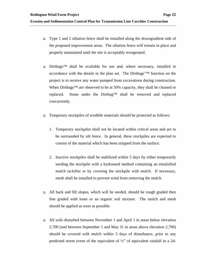
Type 1 and 2 siltation fence shall be installed along the downgradient side of
the proposed improvement areas. The siltation fence will remain in place and
properly maintained until the site is acceptably revegetated.
Dirtbags™ shall be available for use and, where necessary, installed in
accordance with the details in the plan set. The Dirtbags’™ function on the
project is to receive any water pumped from excavations during construction.
When Dirtbags™ are observed to be at 50% capacity, they shall be cleaned or
replaced. Stone under the Dirtbag™ shall be removed and replaced
concurrently.
Temporary stockpiles of erodible materials should be protected as follows:
1. Temporary stockpiles shall not be located within critical areas and are to
be surrounded by silt fence. In general, these stockpiles are expected to
consist of the material which has been stripped from the surface.
2. Inactive stockpiles shall be stabilized within 5 days by either temporarily
seeding the stockpile with a hydroseed method containing an emulsified
mulch tackifier or by covering the stockpile with mulch. If necessary,
mesh shall be installed to prevent wind from removing the mulch.
All back and fill slopes, which will be seeded, should be rough graded then
fine graded with loam or an organic soil mixture. The mulch and mesh
should be applied as soon as possible.
All soils disturbed between November 1 and April 1 in areas below elevation
2,700 (and between September 1 and May 31 in areas above elevation 2,700)
should be covered with mulch within 5 days of disturbance, prior to any
predicted storm event of the equivalent of ½” of equivalent rainfall in a 24-
Redington Wind Farm Project Page 23
Erosion and Sedimentation Control Plan for Transmission Line Corridor Construction
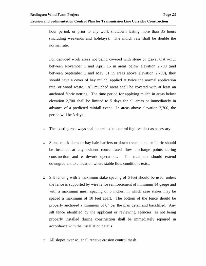
hour period, or prior to any work shutdown lasting more than 35 hours
(including weekends and holidays). The mulch rate shall be double the
normal rate.
For denuded work areas not being covered with stone or gravel that occur
between November 1 and April 15 in areas below elevation 2,700 (and
between September 1 and May 31 in areas above elevation 2,700), they
should have a cover of hay mulch, applied at twice the normal application
rate, or wood waste. All mulched areas shall be covered with at least an
anchored fabric netting. The time period for applying mulch in areas below
elevation 2,700 shall be limited to 5 days for all areas or immediately in
advance of a predicted rainfall event. In areas above elevation 2,700, the
period will be 3 days.
The existing roadways shall be treated to control fugitive dust as necessary.
Stone check dams or hay bale barriers or downstream stone or fabric should
be installed at any evident concentrated flow discharge points during
construction and earthwork operations. The treatment should extend
downgradient to a location where stable flow conditions exist.
Silt fencing with a maximum stake spacing of 6 feet should be used, unless
the fence is supported by wire fence reinforcement of minimum 14 gauge and
with a maximum mesh spacing of 6 inches, in which case stakes may be
spaced a maximum of 10 feet apart. The bottom of the fence should be
properly anchored a minimum of 6” per the plan detail and backfilled. Any
silt fence identified by the applicant or reviewing agencies, as not being
properly installed during construction shall be immediately repaired in
accordance with the installation details.
All slopes over 4:1 shall receive erosion control mesh.

Redington Wind Farm Project Page 24
Erosion and Sedimentation Control Plan for Transmission Line Corridor Construction
Slopes steeper than 3:1 shall receive reinforced turf or reinforced bark mulch.
Type 3 silt fences shall be installed as construction progresses.
Areas of visible erosion shall be stabilized with crushed stone. The size of
the stone shall be determined based upon flow, slopes, and observed field
conditions.
All temporary sedimentation and erosion control measures shall be removed after
construction activity has ceased and healthy vegetation has established itself or
other appropriate permanent control measures have been implemented.
8.0 Standards for Stabilizing Sites for the Winter
8.1 Standard For The Timely Stabilization Of Ditches And Channels
The following additional measures apply to the colder seasons. The
contractor shall construct and stabilize stone-lined ditches and channels
using the standard methods by November 15 (except in elevations above
2,700 where standard methods apply only until September 30). The
contractor shall construct and stabilize all grass-lined ditches and
channels using the standard methods by September 15 (except in areas
above elevation 2,700 where the standard methods apply only until
August 21). If the contractor fails to stabilize a ditch or channel to be
grass-lined by the specified dates, then the contractor shall take one of the
following actions to stabilize the ditch for late fall and winter.
Install A Sod Lining In The Ditch – The contractor shall line the ditch
with properly installed sod. Proper installation includes the applicant
pinning the sod onto the soil with wire pins, rolling the sod to
guarantee contact between the sod and underlying soil, watering the
Redington Wind Farm Project Page 25
Erosion and Sedimentation Control Plan for Transmission Line Corridor Construction
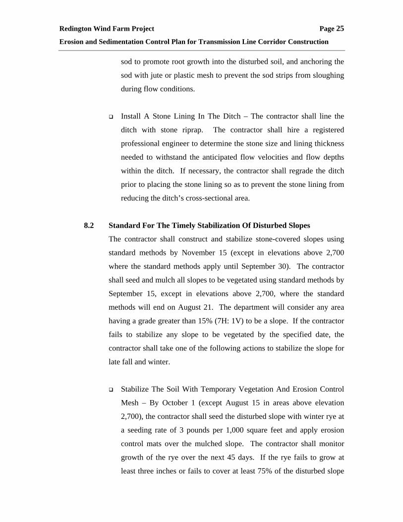
sod to promote root growth into the disturbed soil, and anchoring the
sod with jute or plastic mesh to prevent the sod strips from sloughing
during flow conditions.
Install A Stone Lining In The Ditch – The contractor shall line the
ditch with stone riprap. The contractor shall hire a registered
professional engineer to determine the stone size and lining thickness
needed to withstand the anticipated flow velocities and flow depths
within the ditch. If necessary, the contractor shall regrade the ditch
prior to placing the stone lining so as to prevent the stone lining from
reducing the ditch’s cross-sectional area.
8.2 Standard For The Timely Stabilization Of Disturbed Slopes
The contractor shall construct and stabilize stone-covered slopes using
standard methods by November 15 (except in elevations above 2,700
where the standard methods apply until September 30). The contractor
shall seed and mulch all slopes to be vegetated using standard methods by
September 15, except in elevations above 2,700, where the standard
methods will end on August 21. The department will consider any area
having a grade greater than 15% (7H: 1V) to be a slope. If the contractor
fails to stabilize any slope to be vegetated by the specified date, the
contractor shall take one of the following actions to stabilize the slope for
late fall and winter.
Stabilize The Soil With Temporary Vegetation And Erosion Control
Mesh – By October 1 (except August 15 in areas above elevation
2,700), the contractor shall seed the disturbed slope with winter rye at
a seeding rate of 3 pounds per 1,000 square feet and apply erosion
control mats over the mulched slope. The contractor shall monitor
growth of the rye over the next 45 days. If the rye fails to grow at
least three inches or fails to cover at least 75% of the disturbed slope

Redington Wind Farm Project Page 26
Erosion and Sedimentation Control Plan for Transmission Line Corridor Construction
by November 15, then the contractor shall cover the slope with a layer
of wood waste compost as described in this standard, or with stone
riprap as described in this standard.
Stabilize The Slope With Sod – The contractor shall stabilize the
disturbed slope with properly installed sod by October 1 (except
August 15 in areas above elevation 2,700). Proper installation
includes the contractor pinning the sod onto the slope with wire pins,
rolling the sod to guarantee contract between the sod and underlying
soil, and watering the sod to promote root growth into the disturbed
soil. The contractor shall not use late-season sod installation to
stabilize slopes having a grade greater than 33% (3H: 1V) or having
groundwater seeps on the slope face.
Stabilize The Slope With Wood Waste Compost – The contractor
shall place a six-inch layer of wood waste compost on the slope by
November 15 (October 1 in areas above elevation 2,700). Prior to
placing the wood waste compost, the contractor shall remove any
snow accumulation on the disturbed slope. The contractor shall not
use wood waste compost to stabilize slopes having grades greater than
50% (2H: 1V) or having groundwater seeps on the slope face.
Stabilize The Slope With Stone Rip Rap – The contractor shall place
a layer of stone riprap on the slope by November 15 (October 1 in
areas above elevation 2,700). The contractor shall hire a registered
professional engineer to determine the stone size needed for stability
and to design a filter layer for underneath the riprap.
8.3 Standard For The Timely Stabilization Of Disturbed Soil
By September 15 (August 1 in areas above elevation 2,700) the contractor
shall seed and mulch all disturbed soils on areas having a slope less than
Redington Wind Farm Project Page 27
Erosion and Sedimentation Control Plan for Transmission Line Corridor Construction
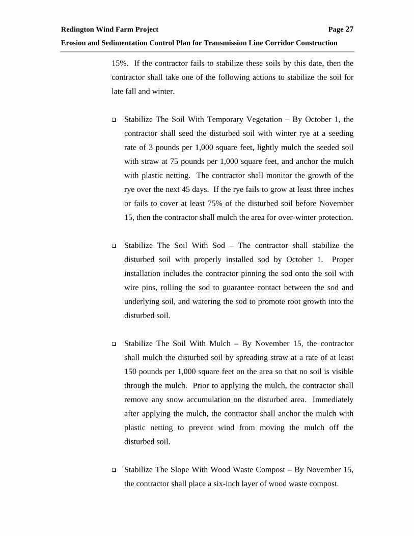
15%. If the contractor fails to stabilize these soils by this date, then the
contractor shall take one of the following actions to stabilize the soil for
late fall and winter.
Stabilize The Soil With Temporary Vegetation – By October 1, the
contractor shall seed the disturbed soil with winter rye at a seeding
rate of 3 pounds per 1,000 square feet, lightly mulch the seeded soil
with straw at 75 pounds per 1,000 square feet, and anchor the mulch
with plastic netting. The contractor shall monitor the growth of the
rye over the next 45 days. If the rye fails to grow at least three inches
or fails to cover at least 75% of the disturbed soil before November
15, then the contractor shall mulch the area for over-winter protection.
Stabilize The Soil With Sod – The contractor shall stabilize the
disturbed soil with properly installed sod by October 1. Proper
installation includes the contractor pinning the sod onto the soil with
wire pins, rolling the sod to guarantee contact between the sod and
underlying soil, and watering the sod to promote root growth into the
disturbed soil.
Stabilize The Soil With Mulch – By November 15, the contractor
shall mulch the disturbed soil by spreading straw at a rate of at least
150 pounds per 1,000 square feet on the area so that no soil is visible
through the mulch. Prior to applying the mulch, the contractor shall
remove any snow accumulation on the disturbed area. Immediately
after applying the mulch, the contractor shall anchor the mulch with
plastic netting to prevent wind from moving the mulch off the
disturbed soil.
Stabilize The Slope With Wood Waste Compost – By November 15,
the contractor shall place a six-inch layer of wood waste compost.
Redington Wind Farm Project Page 28
Erosion and Sedimentation Control Plan for Transmission Line Corridor Construction
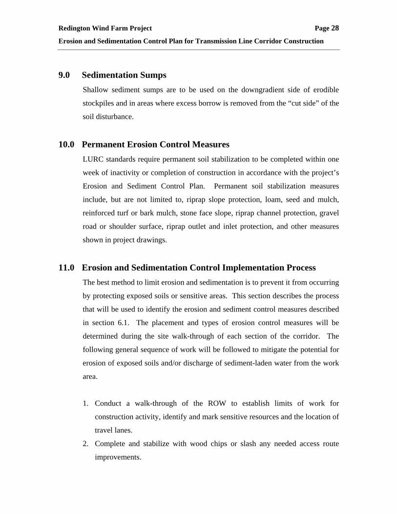
9.0 Sedimentation Sumps Shallow sediment sumps are to be used on the downgradient side of erodible
stockpiles and in areas where excess borrow is removed from the “cut side” of the
soil disturbance.
10.0 Permanent Erosion Control Measures LURC standards require permanent soil stabilization to be completed within one
week of inactivity or completion of construction in accordance with the project’s
Erosion and Sediment Control Plan. Permanent soil stabilization measures
include, but are not limited to, riprap slope protection, loam, seed and mulch,
reinforced turf or bark mulch, stone face slope, riprap channel protection, gravel
road or shoulder surface, riprap outlet and inlet protection, and other measures
shown in project drawings.
11.0 Erosion and Sedimentation Control Implementation Process The best method to limit erosion and sedimentation is to prevent it from occurring
by protecting exposed soils or sensitive areas. This section describes the process
that will be used to identify the erosion and sediment control measures described
in section 6.1. The placement and types of erosion control measures will be
determined during the site walk-through of each section of the corridor. The
following general sequence of work will be followed to mitigate the potential for
erosion of exposed soils and/or discharge of sediment-laden water from the work
area.
1. Conduct a walk-through of the ROW to establish limits of work for
construction activity, identify and mark sensitive resources and the location of
travel lanes.
2. Complete and stabilize with wood chips or slash any needed access route
improvements.

Redington Wind Farm Project Page 29
Erosion and Sedimentation Control Plan for Transmission Line Corridor Construction
3. Install and stabilize temporary equipment crossings over wetlands and
waterbodies. Use timber mats or temporary bridges where necessary.
4. Clear timber and brush. No grubbing will be necessary unless the area
requires leveling for passage of tracked equipment in difficult terrain or for
installation of poles and guys.
5. Install silt fencing or other erosion control barriers around the perimeter of the
work areas.
6. Protect resources along temporary travel lanes within the ROW and protect
resources adjacent to construction laydown and work areas.
7. Construct temporary or permanent water bars, if needed.
8. Level the construction area and conduct any blasting, as needed.
9. Excavate for the poles. Pump excavation seepage and runoff to a temporary
sedimentation trap or Dirtbag™, prior to discharge to a well-vegetated area.
Control and direct runoff from the excavation areas using water bars, berms
or hay bales. Remove excess spoils from site.
10. Monitor any paved public road used for access for signs of tracking and
spilling of spoils on the roadway. Construct a stabilized construction
entrance if needed.
11. Complete pole and conductor installation.
12. Stabilize disturbed soils associated with temporary wetland and stream
crossings within 48 hours of removal of the temporary crossing.
13. Regrade the ROW to original contours, as needed, loam, seed, mulch, and
anchor all exposed soils within 7 days from final grading.
Any deviation from this sequence is subject to approval of the applicant and may
require separate approval of the regulatory officials.
12.0 Contracting Procedure The transmission line will be constructed by subcontractors of the applicant. The
contract documents will require a schedule for the completion of the work which
will satisfy the following criteria:

Redington Wind Farm Project Page 30
Erosion and Sedimentation Control Plan for Transmission Line Corridor Construction
12.1 The Work Shall Be Constructed In Accordance With This Erosion
Control Plan
Work must also be scheduled or phased to prevent the extent of the
exposed areas as stipulated in this plan. The contractor shall also agree
and have the responsibility to control turbidity, to prevent significant
erosion, to control fugitive dust, and to employ the tools outlined in this
plan, and including other measures as may be necessary to meet this
responsibility. The work shall be conducted in sections which will:
Limit the amount of exposed area to those areas in which work is
expected to be undertaken during the next 3 to 4 days.
Revegetate disturbed areas as rapidly as possible.
Incorporate specified inlets, groundwater control, and drainage system
as early as possible into the construction phase. The ditches shall be
immediately lined or revegetated as soon as their installation is
complete.
Comply with the provisions of this section.
Stockpiled material shall be located at least 100’ from any
stream/water body or wetland.
12.2 The Area of Denuded Non-Stabilized Construction Shall Be Limited
To The Minimum Area Practicable
An area shall be considered to be denuded until the surface gravel is
installed on the roadway surface, the final surface treatment constructed,
or the areas have been loamed, seeded, and mulched.
Any deviations from the schedule or provisions contained in this plan
shall require the approval of the permittee. The permittee may elect to
consult with LURC and MeDEP to secure their approval prior to
approving any schedule changes.

Redington Wind Farm Project Page 31
Erosion and Sedimentation Control Plan for Transmission Line Corridor Construction
The contractor must install any added measures which may be necessary
to control erosion/sedimentation from the site, dependent upon the actual
site and weather conditions occurring at the time of construction.
The applicant may be required to retain a third party inspector. The
contractor shall cooperate with the third party inspector and permit access
to the site by the inspector at all times.
13.0 Provisions for Winter or Seasonal Shutdown Because the transmission line construction is required to be completed in small
segments, due to limited access points, the ability to shut down the work for
seasonal or other reasons should be relatively easy. This narrative describes this
shutdown procedure: Any segments of the transmission line where vegetation
has not been reestablished shall be treated as outlined in Section 8.0 of this
narrative.
An inspection shall be made to identify any areas where additional erosion
control work is needed. Such areas shall be repaired.
Subsequently, the transmission line corridor shall be re-inspected after a
significant rainfall. Any eroded areas shall be repaired. Inspections shall follow
for four significant rainfall events.
14.0 Provisions for Maintenance of the Erosion/Sedimentation Control
Features The transmission line construction will be contracted by the applicant. The work
will be subject to the requirement of a MeDEP Storm Water Discharge Permit.
The final provisions of this permit are anticipated to require the applicant and his
contractors to prepare a list and designate by name, address and telephone
number all individuals who will be responsible for implementation, inspection
and maintenance of all erosion control measures identified within this section and
Redington Wind Farm Project Page 32
Erosion and Sedimentation Control Plan for Transmission Line Corridor Construction
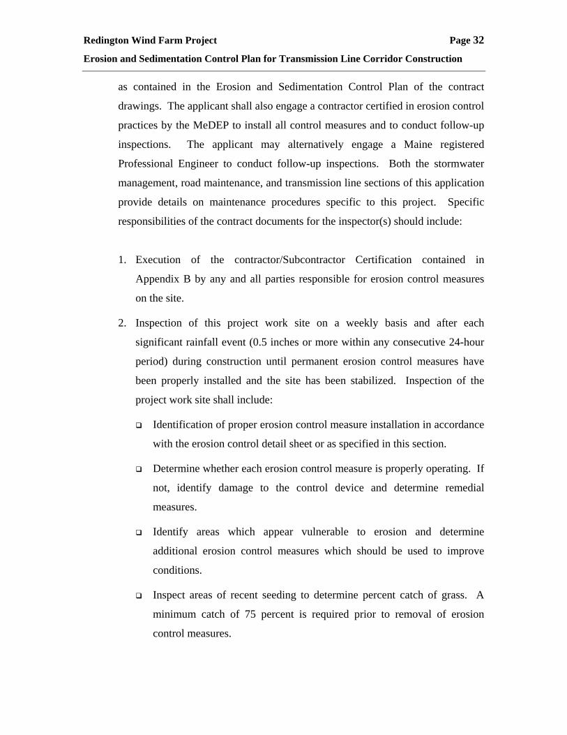
as contained in the Erosion and Sedimentation Control Plan of the contract
drawings. The applicant shall also engage a contractor certified in erosion control
practices by the MeDEP to install all control measures and to conduct follow-up
inspections. The applicant may alternatively engage a Maine registered
Professional Engineer to conduct follow-up inspections. Both the stormwater
management, road maintenance, and transmission line sections of this application
provide details on maintenance procedures specific to this project. Specific
responsibilities of the contract documents for the inspector(s) should include:
1. Execution of the contractor/Subcontractor Certification contained in
Appendix B by any and all parties responsible for erosion control measures
on the site.
2. Inspection of this project work site on a weekly basis and after each
significant rainfall event (0.5 inches or more within any consecutive 24-hour
period) during construction until permanent erosion control measures have
been properly installed and the site has been stabilized. Inspection of the
project work site shall include:
Identification of proper erosion control measure installation in accordance
with the erosion control detail sheet or as specified in this section.
Determine whether each erosion control measure is properly operating. If
not, identify damage to the control device and determine remedial
measures.
Identify areas which appear vulnerable to erosion and determine
additional erosion control measures which should be used to improve
conditions.
Inspect areas of recent seeding to determine percent catch of grass. A
minimum catch of 75 percent is required prior to removal of erosion
control measures.

Redington Wind Farm Project Page 33
Erosion and Sedimentation Control Plan for Transmission Line Corridor Construction
Accumulated silt/sediment should be removed when the depth of sediment
reaches 50 percent of the barrier height. Accumulated silt/sediment should be
removed from behind silt fencing when the depth of the sediment reaches 6
inches.
3. Certification that the contractor’s construction sequence is in conformance
with the specified schedule of this plan. A weekly compliance certification
describing, any deviations and corrective measures necessary to comply with
the erosion control requirements which shall be prepared and signed by the
inspector(s).
4. In addition to the weekly certifications, the inspector(s) shall maintain written
reports recording construction activities on site which include:
Dates when major grading activities occur in a particular area.
Dates when major construction activities cease in a particular area, either
temporarily or permanently.
Dates when an area is stabilized.
5. Modifications to the erosion control plan, either to improve effectiveness or
correct a site-specific deficiency if inspection of the site indicates a change
should be made. The inspector shall immediately notify the contractor and
the applicant that the contractor should implement the corrective measures.
Once construction has been completed, long-term maintenance of the permanent
erosion control measures and storm water systems will be the responsibility of the
applicant.
All certifications, inspection forms, and written reports prepared by the
inspector(s) should be filed with the applicant, and the MCGP Permit File
contained on the project site. All written certifications, inspection forms, and
written reports should be filed within one (1) week of the inspection date.

Redington Wind Farm Project Page 34
Erosion and Sedimentation Control Plan for Transmission Line Corridor Construction
15.0 Preconstruction Conference Prior to any construction at the site, representatives of the MeDEP, LURC, the
transmission line construction contractor, the soils engineer, and the site design
engineer should meet with the applicant to discuss the scheduling of the site
construction and compliance with this plan. By or before that meeting, the
contractor will prepare a detailed schedule and a marked-up site plan indicating
areas and components of the work and key dates showing date of disturbance and
completion of the work. Three copies of the schedule and marked-up site plan
shall be provided to the applicant.
16.0 Closure This Erosion and Sedimentation Control Plan applies to the new transmission line
corridors which will be constructed for the proposed wind farm project. LURC
Chapter 10 Rules and Standards require permanent and temporary erosion and
sedimentation control measures to meet the standards and specifications of the
“MeDEP Erosion and Sediment Control BMP Manual of March 2003” or other
equally effective practices. This Erosion and Sedimentation Control Plan,
accompanying Maintenance Narrative, and project drawings seek to minimize
any unreasonable soil erosion or reduction in the capacity of the land to absorb
and hold water. Any deviation from the requirements of this plan shall be
reviewed with the Permittee and may require separate approval from
MeDEP and LURC.

Redington Wind Farm Project Page 35
Erosion and Sedimentation Control Plan for Transmission Line Corridor Construction
ATTACHMENT A
Seeding Plan

Redington Wind Farm Project Page 36
Erosion and Sedimentation Control Plan for Transmission Line Corridor Construction
PERMANENT SEEDING PLAN NON-WETLAND AREAS ABOVE ELEVATION 2700 FEET
Project Redington Wind Farm
Site Location Transmission Line Corridors
X Permanent Seeding Temporary Seeding
1. Area to be seeded: not determined acres, OR M Sq. Ft.
2. Instructions on preparation of soil: Prepare a good seed bed for planting method used.
3. Apply lime as follows: #/acres, OR 138#/M Sq. Ft.
4. Fertilize with pounds of - - N-P-K/ac. OR 18.4 pounds of 10 - 20 - 20 N-P-K/M Sq. Ft.
5. Method of applying lime and fertilizer: Spread and work into the soil before seeding.
6. Seed with the following mixture:
60% Winter Rye 10% Indian Sweet Grass (as available) 10% Tufted Hairgrass (as available) 10% Poverty Oatgrass (as available) 10% Wild Oatgrass (as available)
When using small grain as nurse crop seed it at one-half the normal seeding rate. 7. Mulching instructions: Apply at the rate of ___ tons per acre. OR 180 pounds
per M. Sq. Ft. Amount Unit #, Tons, Etc.
8. TOTAL LIME…………………………………138 #/1000 sq. ft.
9. TOTAL FERTILIZER………………………… 18.4 #/1000 sq. ft.
10. TOTAL SEED…………………………………. 4.0 #/1000 sq. ft.
11. TOTAL MULCH………………………………115 #/1000 sq. ft.
12. TOTAL other materials, seeds, etc.……………
13. REMARKS
• Recommended seeding dates: Varies with elevation; see narrative.
• For areas with slopes >10%, waterways, areas within 100 feet of wetlands,
and fall and winter erosion control areas, mulch netting shall be used per
manufacturer’s specifications.

Redington Wind Farm Project Page 37
Erosion and Sedimentation Control Plan for Transmission Line Corridor Construction
Fertilizer requirements shall be subject to actual test results of the topsoil used for
the project. The contractor shall be responsible for providing topsoil test results
for pH and recommended fertilizer application rates to the permittee.
Redington Wind Farm Project Page 38
Erosion and Sedimentation Control Plan for Transmission Line Corridor Construction
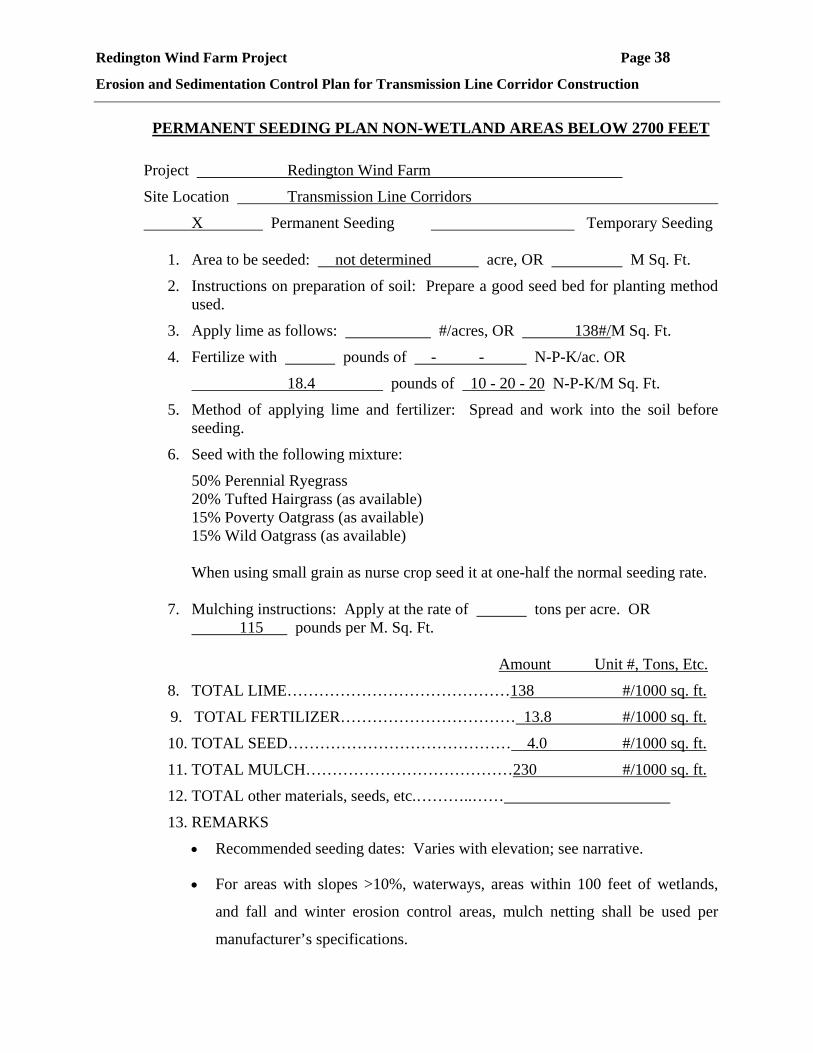
PERMANENT SEEDING PLAN NON-WETLAND AREAS BELOW 2700 FEET
Project Redington Wind Farm
Site Location Transmission Line Corridors
X Permanent Seeding Temporary Seeding
1. Area to be seeded: not determined acre, OR M Sq. Ft.
2. Instructions on preparation of soil: Prepare a good seed bed for planting method used.
3. Apply lime as follows: #/acres, OR 138#/M Sq. Ft.
4. Fertilize with pounds of - - N-P-K/ac. OR
18.4 pounds of 10 - 20 - 20 N-P-K/M Sq. Ft.
5. Method of applying lime and fertilizer: Spread and work into the soil before seeding.
6. Seed with the following mixture:
50% Perennial Ryegrass 20% Tufted Hairgrass (as available) 15% Poverty Oatgrass (as available) 15% Wild Oatgrass (as available) When using small grain as nurse crop seed it at one-half the normal seeding rate.
7. Mulching instructions: Apply at the rate of tons per acre. OR
115 pounds per M. Sq. Ft.
Amount Unit #, Tons, Etc.
8. TOTAL LIME……………………………………138 #/1000 sq. ft.
9. TOTAL FERTILIZER…………………………… 13.8 #/1000 sq. ft.
10. TOTAL SEED…………………………………… 4.0 #/1000 sq. ft.
11. TOTAL MULCH…………………………………230 #/1000 sq. ft.
12. TOTAL other materials, seeds, etc.………..……
13. REMARKS
• Recommended seeding dates: Varies with elevation; see narrative.
• For areas with slopes >10%, waterways, areas within 100 feet of wetlands,
and fall and winter erosion control areas, mulch netting shall be used per
manufacturer’s specifications.

Redington Wind Farm Project Page 39
Erosion and Sedimentation Control Plan for Transmission Line Corridor Construction
Fertilizer requirements shall be subject to actual test results of the topsoil used for the
project. The contractor shall be responsible for providing topsoil test results for pH and
recommended fertilizer application rates to the permittee.

Redington Wind Farm Project Page 40
Erosion and Sedimentation Control Plan for Transmission Line Corridor Construction
SEEDING PLAN WETLAND AREAS ALL ELEVATIONS
Project Redington Wind Farm
Site Location Transmission Line Corridors
X Permanent Seeding Temporary Seeding
1. Area to be seeded: Not Determined acre, OR M Sq. Ft.
2. Instructions on preparation of soil: Prepare a good seed bed for planting method used.
3. Apply lime as follows: #/acres, OR 138#/M Sq. Ft.
4. Fertilize with pounds of - - N-P-K/ac. OR 18.4 pounds of 10 - 20 - 20 N-P-K/M Sq. Ft.
5. Method of applying lime and fertilizer: Spread and work into the soil before seeding.
6. Seed with the following mixture:
35% Annual Rye 35% Wool Grass 30% Blue Joint Grass
When using small grain as nurse crop seed it at one-half the normal seeding rate. 7. Mulching instructions: Apply at the rate of tons per acre. OR
180 pounds per M. Sq. Ft. Amount Unit #, Tons, Etc. 8. TOTAL LIME……………………………………..138 #/1000 sq. ft.
9. TOTAL FERTILIZER…………………………….18.4 #/1000 sq. ft.
10. TOTAL SEED……………………………………. 5.0 #/1000 sq. ft.
11. TOTAL MULCH………………………………….180 #/1000 sq. ft.
12. TOTAL other materials, seeds, etc.…..…………
13. REMARKS
The above seed mix is required in all temporarily disturbed wetland areas.
Fertilizer requirements shall be subject to actual test results of the topsoil used for
the project. The contractor shall be responsible for providing topsoil test results
for pH and recommended fertilizer application rates to the permittee.

Redington Wind Farm Project Page 41
Erosion and Sedimentation Control Plan for Transmission Line Corridor Construction
TEMPORARY SEEDING PLAN NON-WETLAND AREAS ALL ELEVATIONS
Project Redington Wind Farm
Site Location Transmission Line Corridors
Permanent Seeding X Temporary Seeding
5. Area to be seeded: not determined acre, OR M Sq. Ft.
6. Instructions on preparation of soil: Prepare a good seed bed for planting method used.
7. Apply lime as follows: #/acres, OR 138#/M Sq. Ft.
8. Fertilize with pounds of - - N-P-K/ac. OR 18.4 pounds of 10 - 20 - 20 N-P-K/M Sq. Ft.
7. Method of applying lime and fertilizer: Spread and work into the soil before seeding.
8. Seed with the following mixture:
100% Winter Rye
When using small grain as nurse crop seed it at one-half the normal seeding rate. 8. Mulching instructions: Apply at the rate of tons per acre. OR
230 pounds per M. Sq. Ft. Amount Unit #, Tons, Etc.
14. TOTAL LIME…………………………………..138 #/1000 sq. ft.
15. TOTAL FERTILIZER………………………….18.4 #/1000 sq. ft.
16. TOTAL SEED…………………………………. 4.0 #/1000 sq. ft.
17. TOTAL MULCH……………………………….115 #/1000 sq. ft.
18. TOTAL other materials, seeds, etc.………………
19. REMARKS
Spring seeding is recommended, however, late summer (prior to date specified in
narrative) seeding can be made. Permanent seeding should be made prior to date
specified in narrative or as a dormant seeding after the first killing frost and
before the first snowfall. If seeding cannot be done within these seeding dates,
temporary seeding and mulching shall be used to protect the site. Permanent
seeding shall be delayed until the next recommended seeding period.

Redington Wind Farm Project Page 42
Erosion and Sedimentation Control Plan for Transmission Line Corridor Construction
Fertilizer requirements shall be subject to actual test results of the topsoil used for
the project. The contractor shall be responsible for providing topsoil test results
for pH and recommended fertilizer application rates to the permittee.

Redington Wind Farm Project Page 43
Erosion and Sedimentation Control Plan for Transmission Line Corridor Construction
ATTACHMENT B
Sample Certification and Inspection Forms
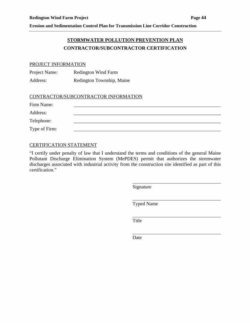
Redington Wind Farm Project Page 44
Erosion and Sedimentation Control Plan for Transmission Line Corridor Construction
STORMWATER POLLUTION PREVENTION PLAN
CONTRACTOR/SUBCONTRACTOR CERTIFICATION
PROJECT INFORMATION
Project Name: Redington Wind Farm
Address: Redington Township, Maine
CONTRACTOR/SUBCONTRACTOR INFORMATION
Firm Name:
Address:
Telephone:
Type of Firm:
CERTIFICATION STATEMENT
“I certify under penalty of law that I understand the terms and conditions of the general Maine Pollutant Discharge Elimination System (MePDES) permit that authorizes the stormwater discharges associated with industrial activity from the construction site identified as part of this certification.” Signature Typed Name Title Date
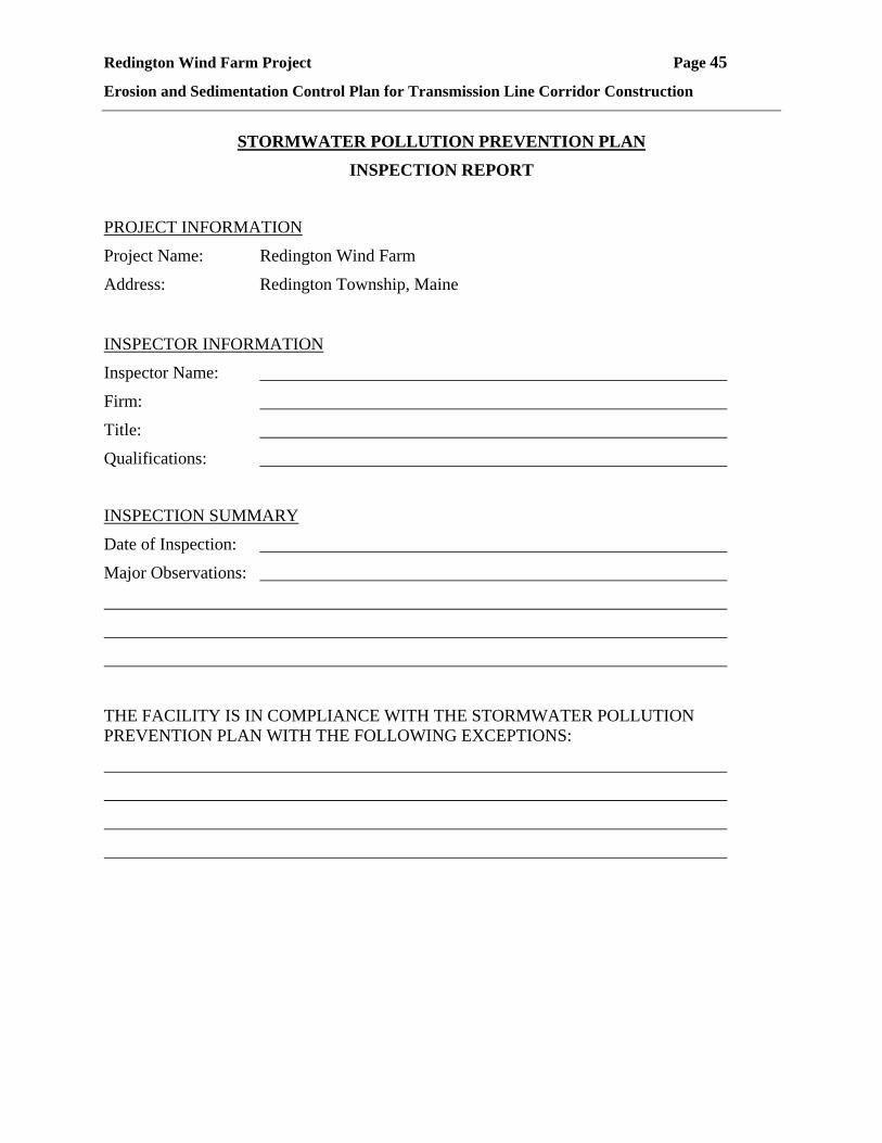
Redington Wind Farm Project Page 45
Erosion and Sedimentation Control Plan for Transmission Line Corridor Construction
STORMWATER POLLUTION PREVENTION PLAN
INSPECTION REPORT
PROJECT INFORMATION
Project Name: Redington Wind Farm
Address: Redington Township, Maine INSPECTOR INFORMATION
Inspector Name:
Firm:
Title:
Qualifications:
INSPECTION SUMMARY
Date of Inspection:
Major Observations:
THE FACILITY IS IN COMPLIANCE WITH THE STORMWATER POLLUTION PREVENTION PLAN WITH THE FOLLOWING EXCEPTIONS:

Redington Wind Farm Project Page 46
Erosion and Sedimentation Control Plan for Transmission Line Corridor Construction
ACTIONS NECESSARY TO BRING FACILITY INTO COMPLIANCE:
REQUIRED MODIFICATIONS TO STORMWATER POLLUTION PREVENTION PLAN (MUST BE IMPLEMENTED WITHIN 7 DAYS OF INSPECTION):
CERTIFICATION STATEMENT:
“I certify under penalty of law that this document and all attachments were prepared under my direction or supervision in accordance with a system designed to assure that qualified personnel properly gathered and evaluated the information submitted. Based on my inquiry of the person or persons who manage the systems, or those persons directly responsible for gathering the information, the information submitted is, to the best of my knowledge and belief, true, accurate and complete. I am aware that there are significant penalties for submitting false information, including the possibility of fine and imprisonment for knowing violations.”
Signature Typed Name Title Date
Redington Wind Farm Project Page 47
Erosion and Sedimentation Control Plan for Transmission Line Corridor Construction
ATTACHMENT C
Erosion Control Specifications
REDINGTON WINDFARM DECEMBER 2005 REDINGTON TOWNSHIP, MAINE
SECTION 02270 - SLOPE PROTECTION AND EROSION CONTROL
PART 1 - GENERAL
1.1 SECTION INCLUDES
A. Temporary and permanent erosion control systems.
B. Slope Protection Systems.
1.2 RELATED SECTIONS
A. Section 02000 – LURC Permit
B. Section 02100 - Site Preparation
C. Section 02200 - Earthwork
D. Erosion and Sedimentation Control Plan
E. Construction Requirements
1.3 ENVIRONMENTAL REQUIREMENTS
A. The contractor shall protect adjacent properties and water resources from erosion and
sediment damage throughout the life of the contract in accordance with the Erosion and
Sediment Control Plan prepared for this project and in accordance with the requirements
of the LURC Permit and special conditions of the permits. The Erosion and Sediment
Control Report and Site Permits have specific restrictions on seasonal work limits, the
amount of area which can be exposed at a given time, the general sequence of
construction, and contractor monitoring.
SLOPE PROTECTION AND EROSION CONTROL 02270-1

REDINGTON WINDFARM DECEMBER 2005 REDINGTON TOWNSHIP, MAINE
B. The general contractor will be required to designate, by name, a Registered Professional
Engineer or equivalent person responsible for implementation of all erosion control
measures as required by the MeDEP Site Location of Development Permit and LURC
Permit for this project. Specific responsibilities will include:
1. Assuring and certifying the contractor's construction sequence is in conformance
with the specified schedule. In addition, a weekly certification stating compliance,
any deviations, and corrective measures shall be filed with the permittee by this
person. A copy of the certification form is contained the Erosion and Sedimentation
Control Plan.
2. Inspection of the project work site on a weekly basis, with the installation of added
erosion control measures in areas which appear vulnerable to erosion.
3. Inspection of all erosion control measures and drainage inlets after any significant
rainfall. Accumulated silt/sediment should be removed when the depth of sediment
reaches 50 percent of the barrier height. Accumulated silt/sediment should be
removed from behind silt fencing when the depth of the sediment reaches 6 inches.
A significant rainfall shall be defined as over ½ inch of precipitation in any
consecutive 24-hour period.
4. Inspect areas for catch of grass. A minimum catch of 75 percent is required prior to
removal of erosion control measures.
PART 2 - PRODUCTS
2.1 MATERIALS
A. Quick growing grasses for temporary seeding (see seed mixes contained in Erosion and
Sedimentation Plan).
B. Hay or straw bales.
SLOPE PROTECTION AND EROSION CONTROL 02270-2
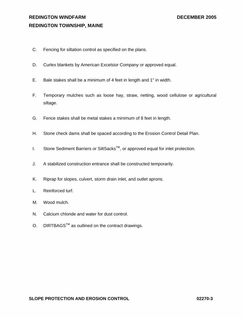
REDINGTON WINDFARM DECEMBER 2005 REDINGTON TOWNSHIP, MAINE
C. Fencing for siltation control as specified on the plans.
D. Curlex blankets by American Excelsior Company or approved equal.
E. Bale stakes shall be a minimum of 4 feet in length and 1" in width.
F. Temporary mulches such as loose hay, straw, netting, wood cellulose or agricultural
siltage.
G. Fence stakes shall be metal stakes a minimum of 8 feet in length.
H. Stone check dams shall be spaced according to the Erosion Control Detail Plan.
I. Stone Sediment Barriers or SiltSacksTM, or approved equal for inlet protection.
J. A stabilized construction entrance shall be constructed temporarily.
K. Riprap for slopes, culvert, storm drain inlet, and outlet aprons.
L. Reinforced turf.
M. Wood mulch.
N. Calcium chloride and water for dust control.
O. DIRTBAGSTM as outlined on the contract drawings.
SLOPE PROTECTION AND EROSION CONTROL 02270-3
REDINGTON WINDFARM DECEMBER 2005 REDINGTON TOWNSHIP, MAINE
PART 3 - EXECUTION
3.1 PREPARATION
A. Review site erosion control plan attached to this section of the specifications.
B. Deficiencies or changes in the erosion control plan as it is applied to current conditions
will be brought to the attention of the Engineer for remedial action.
3.2 EROSION CONTROL AND SLOPE PROTECTION IMPLEMENTATION
A. Provide catalog cuts and information concerning the erosion control products which will
be used for construction for review by the permittee.
B. Provide information concerning the installation of the erosion sedimentation control
including anchorage trench provisions and anchorage devices and spacing for review by
the permittee.
C. Place erosion control systems in accordance with the erosion control plan and in
accordance with approved installation procedures.
D. This contract limits the surface area of erodible earth material exposed by clearing and
grubbing, excavation, borrow and embankment operations. The permittee has the
authority to direct the contractor to provide immediate permanent or temporary pollution
control measures. The contractor will be required to incorporate all permanent erosion
control features into the project at the earliest practical time to minimize the need for
temporary controls. Cut slopes shall be permanently seeded and mulched as the
excavation proceeds to the extent considered desirable and practical.
E. The temporary erosion control systems installed by the contractor shall be maintained as
directed by the Engineer to control siltation at all times during the life of the Contract.
The contractor must respond to any maintenance or additional work ordered by the
Engineer within a 48-hour period.
SLOPE PROTECTION AND EROSION CONTROL 02270-4
REDINGTON WINDFARM DECEMBER 2005 REDINGTON TOWNSHIP, MAINE
F. Any additional material work required beyond the extent of the erosion control plan shall
be paid for by the permittee except where such measures are required to correct
deficiencies caused by the failure of the contractor to construct the work in accordance
with the erosion sediment control plan.
G. Slopes that erode easily shall be temporarily seeded as the work progresses with a
cereal grain of wheat, rye or oats.
END OF SECTION 02270
SLOPE PROTECTION AND EROSION CONTROL 02270-5

REDINGTON WINDFARM DECEMBER 2005 REDINGTON TOWNSHIP, MAINE
LURC PERMIT APPLICATION
Erosion and Sedimentation Control Plan
REDINGTON WINDFARM DECEMBER 2005 REDINGTON TOWNSHIP, MAINE
ATTACHMENT D
Figure T-1