redesign of the eskom cape corridor out-of-step tripping ... · redesign of the eskom cape corridor...
TRANSCRIPT

REDESIGN OF THE ESKOM CAPE CORRIDOR OUT-OF-STEP TRIPPING SCHEME
A Bartylak ESKOM
System Operator
ABSTRACT
In this paper a new design of the ESKOM Out-Of-Step (OOS) tripping scheme is proposed. ESKOM commissioned OOS scheme on the Transmission power transfer corridor to Cape in early nineties based on impedance measuring out-of-step tripping relays positioned in the middle of the corridor. Latest reinforcements of the Transmission system, addition of gas turbines as well as commissioning of substantial amount of variable Renewable Power Plants (RPPs) have changed the performance of the corridor to an extent that the reliability of the existing OOS tripping scheme have been affected. Investigations presented in this paper showed that the observability of the scheme has been reduced and the sustainability of the island after system separation became questionable in some system configurations. In conclusion this paper recommends replacing existing impedance measuring scheme with Phasor Measurement based Wide Area Protection System (WAPS). The paper also explains merits behind replacing system separation approach with generator dropping scheme to arrest generators’ transient instability induced by system events.
KEY WORDS
Transient instability, Out-Of-Step protection, Phasor Measurements, Wide Area Protection Systems, Network Separation, Generator Dropping Scheme.
INTRODUCTION
The purpose of the OOS scheme is to detect possible unstable operation of generators following severe (multiphase, long duration) faults on the Transmission system. Faults close to Power Station cleared in traditional Zone 2 back-up tripping time (~450ms) may fall in this category. Probability of such faults is very low considering redundant protection and teleprotection systems deployed at Transmission EHV level. Buszone protection, however, is not redundant and failure of Buszone to operate at 400kV substation close to power station may result in violation of transient stability limits.
Loss of transient stability of generators results in their asynchronous (out of step) operation with the
rest of the system and inevitable shut down of all units following multiple pole slips with severe variations of voltages and currents. Such incident, if not interrupted, would result in prolonged voltage oscillations on the network leading to shut down of many connected customers and could result in damage or at least cumulative life expenditure of turbo-generators and/or auxiliary equipment at all power stations exposed to such conditions.
ESKOM identified potential risk of such incidents on long power transfer corridor between remote 2x1000MWs nuclear power station close to Cape Town (Power Station PS A) and the reminder of the ESKOM generation pool, not far from Johannesburg at a distance of approximately 1500km.
To minimize impact of such incidents ESKOM commissioned OOS tripping scheme at two strategically positioned 400kV substations in late nineties. The purpose of the OOS scheme was to separate unstable generators from the rest of the system with sufficient load on created island to sustain their operation after system separation. At that time the system separation was the only sustainable option available. Gen dropping solution was not considered as it could results in voltage collapse of the corridor after separation in some system configurations. Later Undervoltage Load Shedding Scheme (UVLS) was also commissioned to safeguard.
Since then the Cape corridor network has been substantially reinforced with commissioning of additional 2000MWs of gas generation, 6 new Transmission substations and extension of 765kV network down to Cape Town.
Figure 1 illustrates 765kV extension overlapping the back-bone 400kV series compensated network.
After commissioning of 765kV corridor full system separation was to be achieved by unblocking Power Swing Blocking functions on 765kV lines. Such unblocking should result in tripping of the line during unstable power swings associated with loss of transient stability.
The figure 1 also indicates schematically location of present OOS scheme, impedance measurement area and network separation points.

Extension of 765kV corridor paralleled the existing 400kV corridor which significantly affected overall impedance of combined corridor. This also affected operation and performance of installed OOS tripping scheme.
OPERATION AND PERFORMANCE OF THE IMPEDANCE OOS SCHEME
The existing OOS system separation scheme is based on traditional impedance measurement which differentiates between system faults and power swings by measuring impedance locus speed of movement on the X/R plane. For this measurement relays with 2 impedance characteristics are commonly used and the time difference between their successive pick-ups is converted into speed of movement in ohms/second or equivalent swing frequency in Hz. Many relays deploy 3 measuring characteristics for enhanced security and flexibility of application. An example of out-of-step tripping relay characteristics is shown on figure 2 below.
To verify prospective performance of the existing scheme on the network the OOS relays were modelled on simulator and number of scenarios of possible unstable conditions were simulated. The evaluation included observability of the system as well as performance of created island after system separation.
Detailed analysis indicated deficiencies of current solution in present system configuration and in particular in future development of the network with increasing penetration of renewable power plants (RPPs) in the area.
Reduced impedance between Power Station PS A generators and the system resulted in impedance locus movement a lot closer to PS A generators. The OOS relays installed at Substations SS A and SS B are still able to detect unstable conditions and issue a separation command in most system configurations but the unblocked impedance relays on SS C–SS D 765kV line are not able to complete network separation. The zero voltage electrical centre does not cross this line and enters either SS D 765/400kV transformer or after number of out-of-step cycles SS D–SS E 765kV line. Tripping of SS D–SS E 765kV line, however, does not separate the network still coupled via SS D 765/400kV transformer.
As immediate remedial action an additional Direct Transfer Tripping (DTT) has been commissioned to trip the SS D-SS C 765kV breaker at substation SS D on every operation of OOS scheme either at Substation SS A or SS B. In some circumstances, however, particularly with one PS A generator out of service, the existing OOS tripping scheme may not be able to detect OOS conditions due to electrical centre being out of impedance measurement reach.
Analysis of possible solutions to ensure reliable operation of OOS scheme in all system configurations including envisaged future developments revealed that application of impedance measurement method for detection of unstable conditions would require installation of number of additional OOS impedance relays on a lot more meshed network around Cape Town to be
Figure 2. Example of impedance characteristics used for detection of power swings.
275.250.225.200.175.150.125.100.75.050.025.0-25.0-50.0-75.0-100.-125.-150.-175.-200. [pri.Ohm]
175.
150.
125.
100.
75.0
50.0
25.0
-25.0
-50.0
-75.0
-100.
-125.
-150.
-175.
[pri.Ohm]
Droerivier - Muldersvlei (Kappa) OSTZone (All): Pol +Seq Zl A -119.94 - j 1287.704 pri.Ohm Zl B -1.#IO + j -1.#IO pri.Ohm Zl C -119.94 - j 1287.704 pri.OhmTripping Time: 0.8832641 s
Figure 1. Corridor network of 1997 and 2017 with indicated locations of OOS Tripping Scheme

able to measure electrical centre location closer to PS A. The OOS relays would have to be installed also on SS D 765/400kV transformer as well as on both gen transformers of PS A units. Unblocking of all impedance relays on the network cannot be considered due to uncontrolled separation of the network without any guaranties of active power balance after separation.
In addition it became clear that the impedance measurement method to detect unstable conditions performs best during classical behaviour of the network that can be simplified to two machine oscillations. Our present network configuration with additional generation commissioned and more expected in future does not guarantee such behaviour.
High costs, complexity and questionable reliability of such system directed the OOS investigation into more modern, directly applicable and relatively simple technology based on Phasor Measurement Units (PMUs).
APPLICATION OF WAPS TO OOS DETECTION
Very attractive method that can be simple, reliable and sufficient to detect all possible OOS conditions no matter how they were initiated and in what system configurations is to deploy direct measurement of angle between PS A generators’ terminal voltage and voltage of the main generation pool as indicated on figure 3 below.
Phasor Measurement Units (PMUs) have been designed specifically for this purpose, have long history of being used in monitoring manner, including in ESKOM, and are considered a fully mature technology. By connecting the two PMUs together via telecommunication system a simple and reliable scheme can be proposed where an angle between PS A voltage and the reference voltage is measured and OOS tripping command
can be issued once this angle indicates out-of-phase operation (over 180 deg) of PS A generators with regard to the rest of the interconnected system. Such scheme is inherently independent of system configuration, loading, generation pattern, etc. and it is immune to any network expansion. Similar systems are commissioned in other countries in the world.
Voltage Angle Measurement at PS A
For effective detection of out–of-step operation of PS A generators the measurement must be taken from both units generators’ terminals. This is necessary to detect conditions where zero voltage electrical centre enters gen transformer impedance and not the impedance of transmission lines or transformers. This measurement, if necessary, can be moved to HV side of PS A gen transformers and the terminal voltage angle can be computed by means of calculating voltage drop across the gen transformer impedance, which is dynamically constant. For this calculation gen transformer HV current must be measured and voltage drop across the transformer calculated and subtracted from the measured voltage at HV side. Such arrangement is possible but would add unnecessary complications (voltage selector circuit to cover for possible different linking of gen transformers) reducing overall reliability of the scheme. Preferably direct measurement of generator terminal voltage should be used.
In some circumstances the zero voltage electrical centre doesn’t even cross PS A gen transformers but enters generator impedance directly. In such conditions one of PS A generator Pole Slip protection should operate resulting in generators shut down. This protection cannot be substituted by OOS system but attempts can be considered to detect OOS condition before generator Pole Slip protection will operate i.e. just after the first OOS swing to limit impact on turbo-generators and to facilitate trip-to-house-load operation.
Reference Voltage Angle Measurement
The most important aspect in selection of reference voltage is its location. On more meshed network topology with generators spread across the network Eigenvalue analysis is usually necessary to identify pools of generators that behave in similar manner during instability. On the considered corridor where the PS A plays predominant role the main generation pool behaves essentially like infinite busbar and it is sufficient to select substation where voltage oscillations are negligible during corridor instability.
Figure 3. Angle between PS A and the system voltages as direct indication of synchronous operation.

Measurement too far away from PS A may result in high standing angle difference which may affect speed and security of the scheme. It may also affect speed and reliability of communication channels.
Number of dynamic simulations were performed to ensure that the location of reference voltage will provide required performance of the scheme.
The system was studied in normal conditions and with different sets of outages, loading and generation patterns.
Close-by and long duration far away faults were simulated and voltage angles and magnitudes at many busbars were monitored. The purpose of these simulations was to prove that for any simulated conditions voltages at selected busbar(s) remain measurable during out-of-step conditions and reflective of “the rest of the system”. Example of one simulation result is shown on figure 4 for illustration.
Only on two occasions out of all simulations 400kV voltage at SS A showed out-of-step conditions with regard to the reference voltage indicating electrical centre between SS A and SS F. SS F voltage did not. Therefore one substation away from SS F i.e. either SS G or SS H will provide appropriate
reference to detect OOS conditions in all possible scenarios. Loss of system synchronism as a result of faults at either SS G or H 400kV is only possible for a very long duration 3 phase faults above 3 seconds. Such faults are close to impossible on Transmission network considering level of local and remote back-ups. Moreover faults on busbars selected for PMU installation should not create serious problems either as for OOS detection the most important is to measure angle after the fault has been cleared and when voltages are recovering.
The results indicated locations at SS G and SS H 400kV as fully adequate.
To cater for possible outages of PS A units and to provide adequate redundancy two fully independent systems are proposed:
System 1 - to measure voltage angle between PS A Unit 1 and SS H 400kV and
System 2 - to measure voltage angle between PS A Unit 2 and SS G 400kV.
OOS detection algorithm
The algorithm to detect corridor unstable conditions must be able to detect transient instability caused by any possible event on the network (faults in particular) in any system and generation configuration as well as loading of the network.
The algorithm must be immune to future network development including possible high penetration of renewable power plants with associated reduced system inertia or commissioning of additional large synchronous generation.
The algorithm must remain stable for any possible event on the network that does not result in system instability.
The algorithm shall remain stable during intermittent failures of time synchronisation or communication with remote PMUs. It shall also remain stable on return to service of failed time synchronisation or communication channel.
To verify validity of the approach to use PMU measurements for OOS tripping a model of such OOS system was developed in power system simulator and tested on cases where “blind spots” were found in existing scheme.
The OOS scheme was installed (on simulator) at substation SS H and measured voltage angle between PS A generator terminal voltage and SS H 400kV busbar voltage. Three algorithms were implemented and tested:
Figure 4. Voltage angle on 12 400kV Transmission busbars during PS A instability, example.
1014.918.0822.3726.7631.0535.4 [ms]
197.5
118.4
39.38
-39.69
-118.8
-197.8
[deg]
Koeberg 1: Rotor angle with reference to reference machine angleKoeberg U1 24kV: Voltage, Relative AngleKoeberg 400kV: Voltage, Relative AngleAcacia 400kV: Voltage, Relative AngleMuldersvlei 400kV: Voltage, Relative AngleKappa 400kV: Voltage, Relative AngleDroerivier 400kV: Voltage, Relative AngleHydra 400kV: Voltage, Relative AngleBeta 400kV: Voltage, Relative AngleGrootvlei 400kV: Voltage, Relative AnglePluto 400kV: Voltage, Relative AngleKendal 400kV: Voltage, Relative Angle
SS G and SS H
voltage angles
PS A Rotor Angle
PS A Terminal Voltage Angle
PS A HV Voltage Angle
SS E Voltage Angle
SS D Voltage Angle
SS A Voltage Angle
SS F Voltage Angle
SS G Voltage Angle
SS H Voltage Angle

• Pure measurement of angle δ between voltages with trip command issued at the angle:
δ > 180deg
Such simple algorithm could operate prematurely due to potential large standing angle between measurement points or unnecessarily in case of loss of time synchronisation. This algorithm also cannot detect OOS within generator impedance (pole slip).
• Measurement of slip frequency between the two voltages (dδ/dt) and speed of slip frequency change (angle acceleration – d2δ/dt or RoCoF). Trip command is issued when both slip frequency and acceleration exceed pre-set limits Ks and Ka for specific duration of time T:
dδ/dt > Ks and d2δ/dt > Ka
This algorithm is used in SEL-3378 Synchrophasor Vector Processor Relay successfully implemented in Brazil and Uruguay (OOS schemes), Peru and Georgia (Gen dropping schemes). It can also detect generator pole slip conditions, if required.
• Measurement of slip frequency between the two voltages (dδ/dt) and speed of slip frequency change (angle acceleration – d2δ/dt or RoCoF). Trip command is issued when magnitude of composite vector of slip frequency and angle acceleration exceeds pre-defined level Ksa for a specific time duration Tsa:
(K*dδ/dt)2+ (d2δ/dt)2 > (Ksa)2
This algorithm constitutes a circular or elliptic characteristic of slip frequency and angle acceleration between the two measured voltages. The advantage of this algorithm is fast operation. It can also detect generator pole slip conditions.
More algorithms or combination of different algorithms can be considered to improve dependability and security of the scheme depending on market offerings and internal tests.
The initial tests of PMU based OOS tripping scheme with the above three algorithms showed excellent performance in both stable and unstable conditions. The slip frequency and acceleration of the angle between the two voltages differs so much during stable swings and unstable out-of-step conditions that the detection of correct tripping conditions seems to be very reliable.
Figure 5 shows plots of angle acceleration on vertical axis (Hz/s) against slip frequency on horizontal axis (Hz). Two conditions are plotted on figure 5 – the smaller blue trajectory represents movement of speed/acceleration vector during marginally stable condition – on critical clearance time (CCT) and the bigger red trajectory
represents the same vector movement during out-of-step conditions ~ 1 millisecond above CCT.
The trajectories of such vectors indicate excellent separation between stable and unstable conditions which can be used in detection algorithms.
As mentioned before, simulations also showed that in some circumstances the electrical centre crosses PS A generators’ impedance and not even gen transformers’ impedance, which theoretically should be beyond the reach of proposed OOS scheme which measures voltage angle between PS A generators’ terminals and “the rest of the system” as this voltage angle departs by less that 180 deg. However, the two tested algorithms based on measurement of speed and acceleration still operated correctly after the first swing.
Another advantage of algorithms based on speed and acceleration is that they should be immune to loss of time synchronisation as this will manifest itself in very slow movement of angle well below thresholds of speed and acceleration settings and as such the scheme should be fully functional even
Possible Tripping Characteristic
20.0015.0010.005.000.00-5.00 [Hz]
375.00
250.00
125.00
0.00
-125.00
PMUCalcDSL: Slip frequency in Hz / Slip frequency change in Hz/sPMUCalcDSL: Slip frequency in Hz / Slip frequency change in Hz/s
Power Swing on Critical Clearance
Time - Blue
Figure 5. Speed/Acceleration vector trajectory during stable (blue) and unstable (red) swings.

if the synchronisation is lost for prolonged periods. Pure angle measurements (d > 180deg) does not have this immunity and is dependent on standing angle difference as a result of normal power transfer therefore much less secure.
Telecommunication Requirements
Fast and reliable communication between remote PMUs and OOS IED is a critically important element for successful implementation of PMU based OOS scheme.
Continuous communication of phasor magnitude and angle from PMU to OOS IED with latency shorter than 100ms and availability higher than 99.99% is required.
The telecommunication channels must ensure N-1 compliance i.e. failure of any single component or subsystem of the telecommunication network shall not result in failure of communication channel. Channels used to improve reliability of the system must not have any common modes of failures.
In case single channels are not able to provide required reliability two or more independent channels may be necessary.
Time Synchronization
Precise angle measurement is highly dependent on time stamping therefore high precision time synchronisation of every deployed PMU and OOS IED is important. Due to possible intermittent failures or fading of GPS type of synchronisation an alternative solutions could be considered such as deployment of Atomic Clocks unless detection algorithms are fully immune to synchronisation failures and stable on return and instantaneous re-adjustment of time stamp.
FREQUENCY STABILITY OF THE ISLAND
The most important aspect for successful island is its ability to control frequency. Separation from the transmission system always leaves an island in either excess or deficit of active power, which means that the available governing to reduce increasing frequency as well as available Under Frequency Load Shedding (UFLS) to trim the load in case of underfrequency has to be sufficient after separation. Therefore the following two conditions may result in unsustainable island:
1. If the amount of power generation on the island is high (including all RPPs currently installed and to be installed in the future) and the load on the island is low, substantial amount of power will be exported from separation points to the rest of the system. In such cases system separation may not
be successful if the frequency would be rising faster than RoCoF relays settings or would reach levels of overfrequency settings after separation. As a result PS A generators would trip and the whole island would collapse.
2. If the amount of power generation on the island is low (e.g. no or little generation from RPPs and/or with some generation outages) and the load on the island is high, substantial amount of power will be imported via separation points. In such conditions system separation could result in active power deficit on the island higher than capability of UFLS scheme to trim the load after separation. UFLS scheme design caters for a maximum of 50% of actual load to be shed if all underfrequency stages are activated. Practically it can be safely assumed that 40% of actual load will definitely be disconnected. If this amount of UFLS is not sufficient to arrest frequency above 47Hz the PS A generators will trip and the island will also collapse.
In both situations system separation would result in tripping of PS A generators and a total black-out of the island. In such conditions it is a lot safer for PS A generators and connected customers to use gen dropping option. In this way out-of-step operation of PS A generators will cease immediately and controlled trip-to-house load sequence will be initiated. The transmission network will recover without major consequences. In line with SA Grid Code such incident on the scale of the entire system (i.e. without separation) should not result in frequency drop below 49.0Hz which means that only first few stages of UFLS will be activated. The Transmission system will not be separated therefore ready for synchronisation of PS A generators immediately substantially limiting the extent of the incident.
To detect in what condition the island is operating in terms of the amount of active power deficit or surplus prior to incident a continuous measurement of import or export would be required. For this measurement additional PMUs would have to be installed at the points of separation i.e. at SS A, B and C as well as at generation points at PS B, C and D. Based on this status the OOS System should select between system islanding and gen dropping execution.
The Figure 6 below illustrates the required measurements at the island separation points as well as the additional generation injection points. Active power deficit or surplus of the island (P∆Island) can be calculated by summating all measurements. The addition of power generated by PS B, C and D is required as these generators would have to be shut down after separation to ensure transiently stable island and to improve recovery of PS A generators following OOS conditions. Simulations show that the PS B, C and

D may not regain stability immediately after system separation which would result in prolonged voltage oscillations that may affect stability of PS A generators.
Figure 7 below indicates schematically hardware requirements of a scheme that would fulfil requirements to differentiate between conditions that would require system separation and gen dropping and be able to execute both options.
The system would require 10 PMUs and 28 telecommunication channels. The above illustration does not include any additional redundancies that should be provided for security of such intrusive scheme.
In addition the stability of the island even if the right initial active power balance is measured and achieved becomes more and more questionable considering highly variable and growing output of Renewable Power Plants.
Considering the complexity of such combination of Islanding and Gen Dropping systems as well as growing levels of RPPs and reinforcements of the transmission network it has been concluded to
replace the currently installed separation system with Gen Dropping scheme for all situations of transient instability on the corridor.
For comparison hardware requirements of pure Gen Dropping scheme is shown on figure 8 below.
Such scheme requires 4 PMUs and 2 telecommunication channels. It is obvious that the reliability of such scheme can be expected a magnitude higher than complicated combination of Islanding and Gen. Dropping scheme.
In addition with PS A gen dropping scheme the gen dropping of smaller generators (PS B, C and D) is not needed anymore. If necessary, local “voltage beat” measurement could be implemented to speed up disconnection of any generator that would not regain stability after PS A gen dropping operation.
REDUDNDANCY REQUIREMENTS
Two fully independent systems – one measuring angle between PS A Unit 1 and SS H 400kV substation and the second between PS A Unit 2 and SS G 400kV substation provide for dependability of the scheme (one out of two) and will cater for PS A units’ outages.
As a second layer of redundancy it is proposed to duplicate the two schemes with a requirement for both of them operating (two-out-of-two) to improve security of the system.
Figure 9 below illustrates schematically the proposed system.
Figure 6. System Islanding and Gen Dropping Scheme depending on island loading.
Figure 7. Potential Hardware Requirements for PMU based System Islanding Scheme.
Figure 8. Hardware Requirements for PMU based Gen Dropping Scheme.
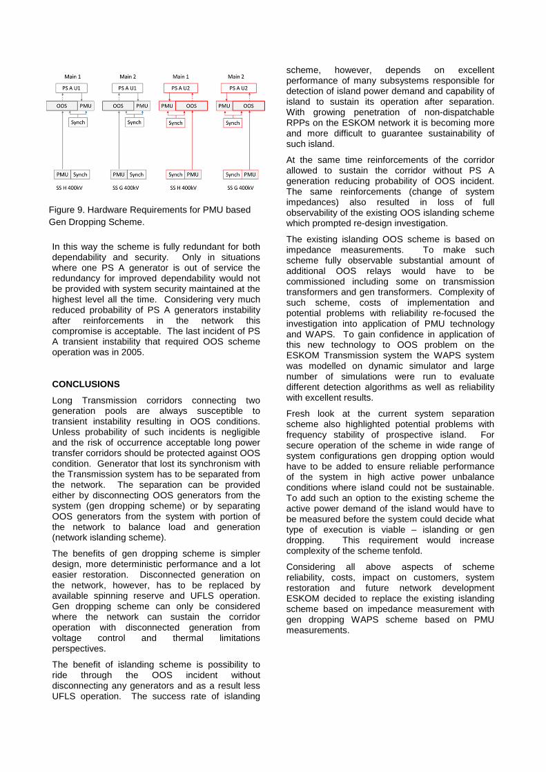
In this way the scheme is fully redundant for both dependability and security. Only in situations where one PS A generator is out of service the redundancy for improved dependability would not be provided with system security maintained at the highest level all the time. Considering very much reduced probability of PS A generators instability after reinforcements in the network this compromise is acceptable. The last incident of PS A transient instability that required OOS scheme operation was in 2005.
CONCLUSIONS
Long Transmission corridors connecting two generation pools are always susceptible to transient instability resulting in OOS conditions. Unless probability of such incidents is negligible and the risk of occurrence acceptable long power transfer corridors should be protected against OOS condition. Generator that lost its synchronism with the Transmission system has to be separated from the network. The separation can be provided either by disconnecting OOS generators from the system (gen dropping scheme) or by separating OOS generators from the system with portion of the network to balance load and generation (network islanding scheme).
The benefits of gen dropping scheme is simpler design, more deterministic performance and a lot easier restoration. Disconnected generation on the network, however, has to be replaced by available spinning reserve and UFLS operation. Gen dropping scheme can only be considered where the network can sustain the corridor operation with disconnected generation from voltage control and thermal limitations perspectives.
The benefit of islanding scheme is possibility to ride through the OOS incident without disconnecting any generators and as a result less UFLS operation. The success rate of islanding
scheme, however, depends on excellent performance of many subsystems responsible for detection of island power demand and capability of island to sustain its operation after separation. With growing penetration of non-dispatchable RPPs on the ESKOM network it is becoming more and more difficult to guarantee sustainability of such island.
At the same time reinforcements of the corridor allowed to sustain the corridor without PS A generation reducing probability of OOS incident. The same reinforcements (change of system impedances) also resulted in loss of full observability of the existing OOS islanding scheme which prompted re-design investigation.
The existing islanding OOS scheme is based on impedance measurements. To make such scheme fully observable substantial amount of additional OOS relays would have to be commissioned including some on transmission transformers and gen transformers. Complexity of such scheme, costs of implementation and potential problems with reliability re-focused the investigation into application of PMU technology and WAPS. To gain confidence in application of this new technology to OOS problem on the ESKOM Transmission system the WAPS system was modelled on dynamic simulator and large number of simulations were run to evaluate different detection algorithms as well as reliability with excellent results.
Fresh look at the current system separation scheme also highlighted potential problems with frequency stability of prospective island. For secure operation of the scheme in wide range of system configurations gen dropping option would have to be added to ensure reliable performance of the system in high active power unbalance conditions where island could not be sustainable. To add such an option to the existing scheme the active power demand of the island would have to be measured before the system could decide what type of execution is viable – islanding or gen dropping. This requirement would increase complexity of the scheme tenfold.
Considering all above aspects of scheme reliability, costs, impact on customers, system restoration and future network development ESKOM decided to replace the existing islanding scheme based on impedance measurement with gen dropping WAPS scheme based on PMU measurements.
Figure 9. Hardware Requirements for PMU based Gen Dropping Scheme.

REFERENCES
[1] “Power System Stability and Control” - P. M. Anderson and A. A. Fouad New York: John Wiley & Sons, 2003.
[2] “Advanced Angle Stability Controls” - Cigre Task Force 38.02.17, April 2000.
[3] “Power System Stability and Control” - P. Kundur, New York: McGraw-Hill, 1994.
[4] “Hydrogenerators behaviour under transient conditions” - CIGRE A1.35 WG Brochure 665, Sep 2016.
[5] “The Total Solution to Phase Angle Stability, Frequency and Voltage Problems for Operating Long-distance Bulk Power Transmission System” - S.Yoshiyama, K.Takafuji, H.Taguchi, K.Hara, Y.Kowada.
[6] “IEEE Standard for Synchrophasor Measurements for Power Systems” - IEEE Std C37.118.1™-2011, New York, NY 10016-5997 USA.
[7] “Real-Time Application of Synchrophasor for Improving Reliability”, NERC, 10/18/2010.
[8] “Advanced Real-Time Synchrophasor Applications” Edmund O. Schweitzer, III, David Whitehead, Armando Guzmán, Yanfeng Gong, and Marcos Donolo, SEL Journal of Reliable Power, Volume 2, Number 2, May 2011