recovery and evaluation of the solid products …
TRANSCRIPT

RECOVERY AND EVALUATION OF THE SOLID PRODUCTS
PRODUCED BY THERMOCATALYTIC DECOMPOSITION OF
TIRE RUBBER COMPOUNDS
A Dissertation
by
LAN LIANG
Submitted to the Office of Graduate Studies of Texas A&M University
in partial fulfillment of the requirements for the degree of
DOCTOR OF PHILOSOPHY
May 2004
Major Subject: Chemical Engineering

RECOVERY AND EVALUATION OF THE SOLID PRODUCTS
PRODUCED BY THERMOCATALYTIC DECOMPOSITION OF
TIRE RUBBER COMPOUNDS
A Dissertation
by
LAN LIANG
Submitted to Texas A&M University in partial fulfillment of the requirements
for the degree of
DOCTOR OF PHILOSOPHY
Approved as to style and content by:
James C. Holste Mark T. Holtzapple (Chair of Committee) (Member) Charles J. Glover Maria A. Barrufet (Member) (Member) Kenneth R. Hall (Head of Department)
May 2004
Major Subject: Chemical Engineering

iii
ABSTRACT
Recovery and Evaluation of the Solid Products Produced by Thermocatalytic
Decomposition of Tire Rubber Compounds. (May 2004)
Lan Liang, B.S., Dalian University of Technology, Dalian, P. R. China
Chair of Advisory Committee: Dr. J.C. Holste
A thermal catalytic decomposition process has been developed to recycle used
tire rubber. This process enables the recovery of useful products, such as hydrocarbons
and carbon blacks. During the catalytic decomposition process, the tire rubber is
decomposed into smaller hydrocarbons, which are collected in the process. The solid
reaction residue, which normally consists of carbon black, catalysts, other inorganic
rubber compound components, and organic carbonaceous deposits, was subjected to a
series of treatments with the intention to recover the valuable carbon black and catalyst.
The process economics depend strongly on the commercial value of the recovered
carbon black and the ability to recover and recycle the catalysts used in the process.
Some of the important properties of the recovered carbon black product have
been characterized and compared with that of commercial-grade carbon blacks. The
composition of the recovered carbon black was analyzed by TGA and EDX, the
structure and morphology were studied through transmission electron microscopy
(TEM), and the specific surface area was measured by BET nitrogen adsorption. The
recovered products possess qualities at least comparable to (or even better than) that of

iv
the commercial-grade carbon black N660. Methods for increasing the market value of
this recovered carbon black product are discussed.
Anhydrous aluminum chloride (AlCl3) was used as the primary catalyst in the
process. A catalyst recovery method based on the AlCl3 sublimation and recondensation
was studied and found to be non-feasible. It is believed that the catalyst forms an
organometallic complex with the decomposed hydrocarbons, such that it becomes
chemically bonded to the residue material and hence not removable by evaporation. A
scheme for the further study of the catalyst recovery is suggested.

v
DEDICATION
To my parents and my husband

vi
ACKNOWLEDGMENTS
I would like to express my sincere appreciation to all the people who helped me
during the course of this research. I am grateful to the study opportunity provided to me
by the Chemical Engineering Department at Texas A&M University.
Special thanks to my advisor, Professor James C. Holste, for his constant
guidance, supervision and inspiration for this work. I would also like to thank
Professors Charles J. Glover, Mark T. Holtzapple, and Maria A. Barrufet for serving on
my committee.
I am especially grateful to Dr. Dawid J. Duvenhage for spending many extra
hours reviewing my work and offering constant guidance on this project. I would also
like to thank Feng Qin, a doctoral student and my research partner, for his help and
kindly discussion.
I appreciate the hard work of Dr. Xianchun Wu in helping me perform the BET
analysis and Dr. Zhiping Luo in training me in the use of TEM and EDX. Additional
thanks are extended to Dr. Clearfield and his research group for letting us use their
equipment to do TGA analysis. I would also like to thank Randy Marek for his
assistance in equipment setup.
I extend my gratitude to S-P Reclamation, Inc. and Cooper Tire & Rubber
Company (the industrial collaborator) for providing the funding for this research. I am
also grateful to the Columbian Chemicals Company for their qualification on our
recovered carbon black products.

vii
I would like to thank my parents and my brother for their love and support
throughout my years of education. Finally, I am grateful to my dear husband, Rui, who
gave me the support and encouragement to bring this work to completion.
viii
TABLE OF CONTENTS
Page
ABSTRACT…………………………………………………………………...…... iii
DEDICATION…………………………………………………………………….. v
ACKNOWLEDGMENTS…………………………………………………………. vi
TABLE OF CONTENTS………………………………………………………….. viii
LIST OF FIGURES………………………………………………………….…….. xii
LIST OF TABLES…………………………………………………………………. xiii
CHAPTER
I INTRODUCTION……………………………………………………….… 1
1.1 Purpose of Investigation……………..…………………………….. 2 1.2 Objectives of this Research………..………………………………. 5
II LITERATURE REVIEW………………………………………………….. 7
2.1 Scrap Tire Disposal & Recycling Technologies.………………….. 7 2.1.1 Tire Derived Fuel………………………………………...… 8
2.1.2 Whole and Processed Rubber Applications…………..…… 11 2.1.3 Decomposing Scrap Tires to Valuable
Chemical Feedstocks……………………….……… 12 2.2 Background Study of Tire Rubber Compound………………….… 16
2.2.1 Properties of Elastomers…………………………………… 18 2.2.2 Vulcanization of Rubber.……………………...…………… 19
2.2.2.1 Vulcanizing Agents.…………………..…………… 20 2.2.2.2 Vulcanizing Activators………………………….…. 24 2.2.2.3 Vulcanizing Accelerators……………………..…… 24 2.2.3 Reinforcement of Rubber…………………………...……... 25
2.3 Background Study of Carbon Black……………………………….. 26 2.3.1 Production of Carbon Black……………………………….. 27 2.3.2 Classification of Carbon Blacks..………………………..… 28 2.3.3 Properties of Carbon Black………………………………… 31

ix
TABLE OF CONTENTS (Continued)
CHAPTER Page
2.3.3.1 Chemical Composition………………………..…… 30 2.3.3.2 Microstructure and Morphology Properties……..… 31
2.3.4 Effects on Rubber Reinforcement…………………….…… 34 2.3.5 Carbon Black Markets…………………………………...… 35 2.3.6 Health and Safety…………………………………..……… 37
2.4 Aluminum Chloride…………………………………………...…… 37 2.4.1 Physical and Chemical Properties of AlCl3…………...…… 37
2.4.2 Molten Mixtures of AlCl3 with other Metal Halides…….… 41 2.4.3 Catalytic Mechanism in Rubber Decomposition Process.… 43
III THERMAL CATALYTIC DECOMPOSITION PROCESS……………… 49
3.1 Introduction………………………………………………………… 49 3.2 Raw Materials……………………………………………………… 51
3.2.1 Rubber Compound…………………………………………. 51 3.2.2 Catalyst………………………….………………….……… 53 3.2.3 Gases…………………………………………….……….… 53
3.3 Thermal Catalytic Decomposition Experiment……………….…… 54 3.3.1 Experimental System…………...…………………….……. 54 3.3.2 Reactor Operating Conditions…………………………...… 56 3.4 Liquid Hydrocarbon Products……………………………………… 57
IV SOLID RESIDUE TREATMENT AND PHYSICAL EVALUATION…………...…………… 62
4.1 Characteristics of Solid Residue…………………………………… 62 4.2 Solid Residue Treatment Procedures…………………….………… 63
4.2.1 Catalyst Removal………………..…………………….…… 64 4.2.2 Residual Wash and Filtration……………………….……… 65 4.2.3 Tetrahydrofuran Extraction (Optional)…………………….. 65 4.2.4 Drying………………………………………...……………. 65
4.3 Physical Evaluation of the Solid Product…………………….……. 67 4.3.1 Carbon Black Yield…………………………………...…… 68
4.3.2 Solid Particle Size Distribution…………………....…….… 70 4.3.3 Composition Analysis of Wash Solution……….…...…..… 72

x
TABLE OF CONTENTS (Continued)
CHAPTER Page
V CARBON BLACK CHARACTERIZATION…………………..………… 78
5.1 Introduction…………………………………………………...…… 78 5.2 Sample Preparation………………………………………………… 79 5.3 Composition Analysis……………………………………………… 80
5.3.1 TGA and Ash Content Determination………….……..…… 80 5.3.1.1 Apparatus………………………………………….. 81 5.3.1.2 Procedures..………………………………….…….. 81 TGA Analysis……………………………………… 81 ASTM Ash Content Determination………...……… 82 5.3.1.3 Results and Discussion…………………………….. 83 5.3.2 Elemental Analysis by EDX……………...…………….….. 87 5.3.2.1 Apparatus………………………………………….. 87 5.3.2.2 Results and Discussion……………………………. 88
5.4 Surface Area Measurement.………………………………….……. 89 5.4.1 Apparatus………………………………….………….…… 90 5.4.2 Results and Discussion………………………………..….... 90
5.5 Structure Characterization…………………………………….…… 93 5.5.1 Terminology..………………………………………….…... 93 5.5.2 Apparatus.……………………………………………….… 94 5.5.3 Results and Discussion.…………………………….….…... 94 5.6 Conclusions………………………………………………………… 98
VI CATALYST RECOVERY STUDY……..…………………….………….. 99
6.1 Introduction..…………………………………………………….… 99 6.2 Vacuum Evaporation Test..………………………………….…….. 100 6.3 Discussion………………………………………………….………. 104
VII CONCLUSIONS AND RECOMMENDATIONS………..……….….…… 107
REFERENCES..………………….……………………………………….……..… 109
APPENDIX A: ELEMENTAL COMPOSITION OF CARBON BLACKS --- ANALYZED BY EDX……………… 118

xi
TABLE OF CONTENTS (Continued)
Page
APPENDIX B: MICROGRAPHS OF CARBON BLACK TAKEN BY TEM..………………………………………..……….. 125
VITA…………………………………………………………………………….…. 134

xii
LIST OF FIGURES
FIGURE Page
2.1 Rubber structures: (a) Natural rubber (repeating unit of cis-1,4-polyisoprene), (b) Styrene-butadiene rubber (repeating unit with 75% butadiene & 25% styrene), (c) Butyl rubber (repeating unit with isoprene unit included)…...… 21
2.2 Structures of sulfur-vulcanized rubber………...……………………...…… 22
3.1 Schematic diagram of the experimental arrangement…………………...… 55
4.1 Carbon black recovery procedures………………………………………… 63
4.2 Particle size distributions of solid products from different rubber feedstock……………………………………….… 74
4.3 Particle size distributions of solid products using different catalyst systems……………………………………….…. 75
5.1 Typical organic compounds in carbon black sample III-03A as identified by GC/MS (based on NIST Chemistry WebBook)…... 86
5.2 Electron micrograph showing the aggregation of virgin commercial grade carbon black N660 particles…………………… 95
5.3 Comparison of recovered carbon black from Run III-10 with commercial carbon black N660 – magnified 100,000 times.……… 96
5.4 Structure of recovered carbon black sample under vacuum degas treatment – magnified 100,000 times………………..……… 97
6.1 Pressure-temperature phase diagram of AlCl3 ……………………….…… 100
6.2 Experimental equipments for catalyst recovery through vacuum evaporation………………………….…………………….. 101

xiii
LIST OF TABLES
TABLE Page
2.1 Estimated TDF Emissions of Metals (Base Fuel - Natural Gas)………...… 10
2.2 Typical Tire Composition by Weight………………………………...……. 13
2.3 A Typical Rubber Compound Formulation…………………………….…. 17
2.4 Selected Properties of the Three Most Common Tire Rubbers…………... 20
2.5 Major Carbon Black Classes and Their Typical Applications in Rubber..... 29
2.6 Effect of Particle Size of Carbon Black on Main Properties of SBR…...…. 36
2.7 Physical properties of Anhydrous Aluminum Chloride………………...…. 39
3.1 Compositions of the Three Model Tire Rubber Compounds………...……. 52
3.2 Reaction Operating Conditions……………………...…………………..…. 58
3.3 Experimental Hydrocarbon Yields..……………………………………..… 60
4.1 Carbon Black Yields……………………………………………………….. 70
4.2 Particle Size Distribution of the Solid Product (wt. %)…………….……… 73
4.3 Quantitative and Qualitative ICP Analysis of Water Washing Filtrates…... 73
4.4 Qualitative GC/MS Analysis of the First Water Filtrate Sample………….. 77
5.1 Composition Analysis of the Carbon Black by TGA and Ash Content Determined Using ASTM Method (wt%)……..….…. 85
5.2 Volatiles Content of the Recovered Carbon Black Products…….………… 85
5.3 Elemental Composition of Recovered Carbon Blacks (Analyzed by EDX)……………………………….……………….. 89

xiv
LIST OF TABLES (Continued)
TABLE Page
5.4 Surface Area and Average Pore Diameter of Recovered Carbon Blacks (Measured by BET)…………………….…………. 91
5.5 Surface Area Alterations of Recovered Carbon Black………..…………… 91

1
CHAPTER I
INTRODUCTION
1.1 Purpose of Investigation
Environmental problems created by discarded tires and waste rubbers have
become significant in recent years. In the United States, an estimated 281 million scrap
tires are generated each year.1 In addition, about 2 billion waste tires already have
accumulated in stockpiles or uncontrolled tire dumps across the country. Millions more
are scattered in ravines, deserts, woods, and empty lots.2 Even though scrap tires occupy
less than 2% in weight of the total solid waste stream, they represent one of the largest
problem areas for polymer reuse and recycling in the United States.
For many years, one of the major disposal options for tires was the scrap pile. A
very significant health problem associated with scrap tire piles is mosquito infestation.3
Mosquitoes are reported to reproduce 4,000 times faster in tire piles than in their natural
environment, and they are known to carry various types of encephalitis and yellow
fever.4 Mosquito infestation of tire piles appears to be a global problem. Large tire
stockpiles are also potential fire hazards. The low bulk density, or loose packing
structure of tires, ensures ample access to air. Once large piles of whole tires begin to
burn, the fire is virtually inextinguishable. In the open, burning tires emit a lot of
undesirable chemicals, including some carcinogens. In addition, substantial quantities of
This dissertation follows the style of the Industrial & Engineering Chemistry Research.

2
petroleum oil are produced and enter neighboring water sources or percolate through the
soil, thereby contaminating the groundwater.
Due to the potential fire and disease hazards, over 48 states in the Unite States
have adopted regulations to manage collection, storage, and disposal of scrap tires. Over
35 states have banned whole tires landfills, and a few states even have banned landfilling
of chopped tires.1 Increasing legislation that restricts the disposal of used tires demands
economically and environmentally sound recycling methods. Now, the issue of how to
effectively and efficiently treat and reuse scrap tires becomes a major issue confronting
the United States and other countries worldwide. The establishment of recycling
technologies for recovering useful resources from the general and industrial wastes for
reutilization is the most desirable solution.5
Some characteristics of tire rubber, such as stability and durability, which are
very attractive and desirable during their use, present a major challenge during the
disposal process. The fact that tires are thermoset polymers means that they are not
easily melted or separated into their chemical components. Tire rubbers are also
virtually immune to biological degradation. The demand for high-quality rubber tires
makes the disposal problem more formidable. Some have described this current
dilemma as “the synthetic rubber problem all over again.”6 The rubber industry faces a
major challenge to find a closed-loop method to recycle this thermoset product.
On the other hand, scrap tires are composed of many valuable constituents,
including both natural and synthetic rubber, carbon black, extender oil, steel, fabrics and
additives. Therefore, the possibility exists to recover valuable products from waste tires.

3
A number of research and commercial efforts have been directed toward developing new
uses for old tires.1-7 However, they either have some undesirable side effects or are not
economically attractive. A more desirable solution, both environmentally acceptable
and economically viable, would be to convert waste tires to reusable hydrocarbon
fractions and carbon blacks. In this way, the original valuable resources from which
polymerized products were created are recovered.
Most attempts to convert tire rubber into chemicals have involved pyrolysis, a
thermal decomposition process in the absence of oxygen. Pyrolysis commonly is
conducted at temperatures above 500 oC, for most hydrocarbons become unstable above
this temperature.8 Pyrolysis processes typically yield 25 to 60% condensable liquids
such as benzene, toluene, etc., 30 to 50% char (a hydrogen-lean carbonaceous product),
and the balance non-condensable fuel gases such as hydrogen, carbon monoxide, carbon
dioxide, and light hydrocarbons. The harsh conditions of pyrolysis tend to produce
hydrocarbons and other products of limited market value. Some methods for improving
the quality of the char have been developed,9 but at the expense of considerable
additional processing.
Recently, a novel patented process has been developed to recycle waste polymers
as an alternative way to recycle scrap tires, which can be less costly and have minimal
adverse impact on the environment.10 This technology employs a thermal catalytic
decomposition process to convert polymeric waste to valuable hydrocarbons and carbon
blacks for reuse. It is noted that molten salts, especially aluminum chloride (AlCl3), of
which the base metal has an electron structure that satisfies the acceptor/donor exchange

4
requirement with the polymer undergoing decomposition, can act as catalysts for
decomposing tire rubbers.10 The fact that molten salt catalysis can be used to decompose
tire rubbers has been known for several decades.11-12 However, to date no literature
reports a successful commercial catalytic conversion process for the disposal of scrap
tires.
Compared to other methods of using scrap tires as an energy source, the recovery
of valuable chemicals appears to be more cost-effective. Besides, it provides an
opportunity to decrease the environmental burden caused by manufacturing fresh
chemical feedstocks from crude oil or natural gas. The thermal catalytic decomposition
process produces hydrocarbon products that generally fall in the range of C4 to C8, with
essentially no light gases, and very few heavier hydrocarbons (or heavy oil) products
present. These products potentially have great value in the fuel and chemical feedstock
markets.
Another significant product, carbon black, could possibly find its market in the
rubber industry. There are approximately thirty grades of carbon black that are
commonly used in various industries. The largest market (about 90%) for carbon black
is in the tire industry where the carbon black enhances tear strength and improves
modulus and wear characteristics of tires.13 However, it is not clear that the recovered
carbon black will retain the superior properties required for reuse in this application.
Additional applications of carbon black are found in plastics, filters, printing inks,
paints, and toners. The market value of carbon black varies widely, depending on its
quality, but generally falls in the range of 30 to 45 cents per pound.2,14 Carbon black

5
extracted from pyrolysis char is of very low purity and therefore cannot be used in tire
manufacturing.15 In contrast, the significantly milder reaction conditions in some
catalytic decomposition processes should produce less useless char and consequently
more higher quality carbon blacks. Therefore, the carbon black product recovered from
the catalytic decomposition process will have a greater market value than that from
pyrolysis processes. The economic value of the carbon black product has the potential to
equal or surpass that of the fluid products.
1.2 Objectives of this Research
The general objective of this research is to develop a thermocatalytic
decomposition process for the conversion of tire rubber compounds to reusable chemical
feedstocks that is both environmentally acceptable and economically viable.
Specifically, the objectives for this study are
1) to develop an operation for processing the solid products from the reaction
residue that separates and recovers carbon black;
2) to determine the reaction conditions under which the yield and quality of
carbon black products are optimum;
3) to evaluate the properties of the recovered carbon black products, to provide a
basis for determining its commercial value and possible applications;
4) to investigate a proper method for recovering and recycling the reaction
catalyst.

6
This investigation is a continuation of earlier work performed in our laboratory
on the recovery of valuable products from scrap tires by thermocatalytic conversion.
The study will provide further laboratory data and understanding required to develop a
commercially viable continuous process that can treat a feed stream consisting of used
tires, plastics, and other polymeric wastes. Based on information gathered here, a pilot
scale reclamation facility will be designed in cooperation with the industrial
collaborators.

7
CHAPTER II
LITERATURE REVIEW
2.1 Scrap Tire Disposal & Recycling Technologies
Tire rubbers are very stable and long-lasting polymers. Progress through decades
in making them more resistant to degradation has extended their useful life, but that
progress has made the disposal process more difficult. The effective and efficient
disposal and recycling of the huge number of scrap tires generated annually becomes a
major issue confronting the United States and other countries worldwide.
The best way to reuse used tires is to remove the outside, or tread, of the tire and
add a new tread, a process referred to as retreading.3 Retreading offers a resource-
efficient strategy for used tire recovery that saves both material and energy.7 Retread
tires most commonly are used for commercial vehicles such as trucks, school buses,
airplanes, and other emergency vehicles. Unfortunately, this market only represents a
very small section of the tire market, and it is slow to expand.16
Scrap tires cannot be reused in a large scale in new tires because of the
vulcanized nature of the rubber. Ground rubber from scrap tires is not chemically the
same as natural rubber or synthetic rubber. The vulcanization process during rubber
compounding transforms the elastomer into a non-fusible and insoluble substance.17 The
rubber cannot be devulcanized during the grinding process. As an analogy made with
baked bread by Serumgard and Eastman16: “Yeast and flour cannot be removed from the
final product and reused again. Old bread cannot be recycled into new bread.” Using

8
reclaimed ground tire material as filler in new tires will cause lower tensile strength, heat
buildup, and oxidative aging. Therefore, ground tire rubber cannot just simply be
reused in new tires. In a sense, Charles Goodyear’s discovery18 of vulcanization in 1839
was not only the real start of the rubber industry, but also of the rubber recycling
industry as well.17 Methods to recycle vulcanized rubber products through
devulcanization, while technically possible in the laboratory, are impractical for large-
scale use.
Some research and commercial efforts have been directed toward the
development of new uses for old tires.1-7 The main strategies of the technology for scrap
tire disposal and recycling can be divided into three categories:19
1) Combustion as fuel;
2) Grinding into small particles and using in civil engineering constructions and
other applications;
3) Decomposing to chemical constituents.
A brief explanation of each recycling technology is given below.
2.1.1 Tire Derived Fuel
Tire Derived Fuel (TDF) as a means of disposal and reuse of scrap tires on an
industrial scale has increased significantly over the past decade. It now is the largest
market for waste tires in the United States. TDF represented approximately 41% of
overall waste tire recycling in 2001.1 Some major combustion facilities for TDF are

9
cement kilns, power plants, pulp and paper boilers, tire manufacturing plants, and small
package steam generators.20
Burning scrap tires as fuel is a way to reduce energy costs. The heat values of
whole tires average about 35,000 kJ/kg (15,000 Btu/lbm), whereas that for most coal is
in the range of 28,000 kJ/kg (12,000 Btu/lbm).21 Waste tires may be burned whole, or
shredded into pieces approximately 1 to 2 inches in size. However, not all tire
components contribute to energy generation because tires contain about 30% of metal
wire and fabric. The removal of the wire involves an expensive process, such as fine
shredding and the use of powerful magnets. Whole tire combustion requires less
processing expense. However, most of the plants currently burning tires for fuel do not
have the capability to burn whole tires.
The potentially harmful effects of burning scrap tires are not fully known. There
are two factors challenging the future markets for TDF. One is the economic feasibility
compared with other fuel alternatives, the other is the technological consideration related
to emission control from the combustion facilities. From 1992 to 1996, the number of
TDF facilities decreased.1 The reasons are assumed to be increasing environmental
pressure and decreasing economic advantage. Although the emission level of pollutants
from TDF facilities is comparable with coal, it is potentially higher than from other
conventional facilities such as natural gas. Studies have shown that the emissions of
metals (zinc, cadmium, lead, nickel, and chromium) are 10 to 100 times higher than
from natural gas. Table 2.1 presents the laboratory simulation results of TDF emissions

10
of metals.22 The test was conducted in a 73 kw (250,000 Btu/h) rotary kiln incinerator
simulator in the EPA’s Environmental Research Center in Research Triangle Park, NC.22
Table 2.1 Estimated TDF Emissions of Metals (Base Fuel - Natural Gas)22
0% TDF (natural gas only)
17% TDF (steady state)
100% TDF (estimated) metals
ng/J lb/MMBtu ng/J lb/MMBtu ng/J lb/MMBtu
antimony 7.72E-05 1.80E-07 9.05E-04 2.10E-06 5.32E-03 1.24E-05
arsenic 4.80E-04 1.12E-06 1.59E-02 3.70E-05 9.35E-02 2.17E-04
beryllium ND ND 2.14E-05 4.98E-08 1.26E-04 2.93E-07
cadmium 1.76E-04 4.09E-07 4.54E-04 1.06E-06 2.67E-03 6.21E-06
chromium 2.78E-04 6.46E-07 1.66E-03 3.86E-06 9.76E-03 2.27E-05
lead 3.45E-03 8.02E-06 2.83E-02 6.58E-05 1.66E-01 3.86E-04
manganese 1.21E-03 2.81E-06 2.48E-03 5.77E-06 1.46E-02 3.40E-05
nickel 3.00E-04 6.98E-07 1.50E-03 3.29E-06 8.82E-03 2.05E-05
selenium 3.56E-04 8.28E-07 1.93E-03 4.49E-06 1.14E-02 2.65E-05
zinc 1.23E-01 2.86E-04 15.21 3.54E-02 89.47 2.08E-01 ng/J – nanograms per joule. lb/MMBtu – pound per million British thermal units. ND – not detected.
Even though burning whole or shredded tires for fuel might seem attractive,
given that the cost of natural gas and other fuel oils continue to increase, one major
drawback still existing is that valuable basic chemical building blocks are consumed,
instead of being recovered.10

11
2.1.2 Whole and Processed Rubber Applications
Due to some unique properties and characteristics of rubbers, such as toughness,
durability, and resilience to impact, tires are used for their second life in new areas
where these merits are beneficial. Whole tires can be used as artificial reefs,
breakwaters, playground equipment, and highway crash barriers.2 Other reuse
alternatives require that tires be split or punched into small particles (1 to 12 inch) or
ground even finely. Shredded tires are being used as a lightweight road construction
material or playground gravel substitutes in civil engineering applications. Split or
punched tires are used to produce many useful products, including floor mats, belts,
gaskets, shoe soles, dock bumpers, seals, and other miscellaneous products. As another
major application, rubber modified asphalt concrete, (RUMAC) is gaining some
attention recently. The addition of crumb rubber in asphalt can improve the asphalt
binder’s rheological properties at low and high temperatures and provide a life up to
three times longer than conventional asphalt.1 In the United States, asphalt rubber is
being used in significant amounts in Texas and Nebraska.
Tire shreds contain significant amounts of steel wire. In comparison, ground
rubber, also referred to as crumb rubber, is a wire-free fine rubber particle made by size
reduction from scrap tires. Various size reduction techniques, such as mechanical
grinding and cryogenic reduction, can be used to achieve a wide range of particle sizes
down to 600 µm or less.1 Ground rubber also can be produced from tire buffings, which
are by-products from the tire retreading process. Using tire rubber for various products

12
typically requires that the steel wire be removed. Currently, steel removal is a costly
process.
From a resource conservation point of view, many applications of the crumb
rubber, such as using as bedding for farm animals, mulch for garden applications, are not
attractive because they represent a waste of valuable chemical resources. In addition,
although it is technically feasible to manufacture many new rubber products from
recycled crumb rubber, several of these new products and processes have poor economic
viability and have very small and limited markets.23 Certain objections also must be
overcome when using crumb rubber in road construction. The increased cost, which can
be 100% more than regular asphalt, is one of the biggest obstacles for the wide
acceptance of rubber modified asphalt concrete. Additionally, the crumb product usually
is sufficiently fine that it poses a serious fire hazard both during the grinding process and
during the lifetime of the application. Therefore, tire derived products cannot replace
completely conventional construction materials, and civil engineering projects do not
consume sufficient quantities of crumb rubber so as to significantly reduce scrap tire
stockpiles.
2.1.3 Decomposing Scrap Tires to Valuable Chemical Feedstocks
The objective of polymer recycling should be two-fold: (1) reduce the volume of
rubbish and the burden on the environment; (2) conserve resources. Scrap tires, as a
type of polymer wastes, are composed of many valuable constituents, including both
natural and synthetic rubber, carbon black, extender oil, steel, fabric, and additives.

13
Table 2.2 lists the typical composition by weight for a passenger tire and a truck tire.24
Noting the drawbacks associated with the first two categories of scrap tire disposal and
recycling methods, many attempts have been made recently toward finding alternative
technologies that are less costly and more resource conservative. Tertiary recycling, a
terminology adopted from the American Plastics Council, is rapidly emerging as an
economical method for reclaiming valuable materials from a variety of polymer-based
waste.23 This recycling method can be applied but not limited to scrap tires, plastics, and
a number of different polymerized products or complex mixtures.
Table 2.2 Typical Tire Composition by Weight24
passenger tire truck tire natural rubber 14% 27% synthetic rubber 27% 14% carbon black 28% 28% steel 14-15% 14-15% fabric, fillers, accelerators, antiozonants, etc. 16-17% 16-17%
average weight new 11.34 kg, scrap 9.07 kg
new 54.43 kg, scrap 45.36 kg
Tertiary recycling breaks down the polymer chains and converts polymers to
low-molecular-weight materials. Both enthalpy and entropy increase during this
process. Thus, from a thermodynamic point of view, it is not desirable. However, the
advantages can compensate.16 Firstly, mixed polymers or polymers with additives such
as fillers and fibers that cannot be separated readily may be degraded to low-molecular-

14
weight substances. These substances can be separated by conventional means, typically
distillation or filtration. Secondly, such low-molecular-weight substances then may be
used for new chemical synthesis, such as polymerization, to make new polymers. The
molecular nature of the resulting polymer can be controlled better than by simply mixing
the original waste polymers. And thirdly, non-renewable petroleum resources are
conserved.
Most attempts to convert tire rubber into chemical feedstocks have involved
pyrolysis, a thermal degradation process in the absence of oxygen. Pyrolysis is
commonly conducted at temperatures above 500 oC, as most hydrocarbons become
unstable above this temperature.8 Pyrolysis processes typically yield three principal
products: gas, oil, and char; each comprises about one third by weight. The fuel gas is
mostly low-molecular-weight hydrocarbons (C1 to C4). The oil fraction has properties
similar to that of conventional heavy fuel oil. The char is a hydrogen-lean carbonaceous
particulate composed of carbon black, ash, and other inorganic materials, such as zinc
oxide, carbonates, and silicates.25
To date, no pyrolysis processes have been commercialized successfully. The
problems blocking them have been both technical and economic. The harsh pyrolysis
conditions tend to produce hydrocarbons and carbon/char products of limited market
value. Some methods for improving the quality of the char have been developed,9 but at
the expense of considerable additional operating cost and the capital cost of the plant.
At high temperatures, vulcanized rubber decomposes quickly to low-molecular-weight
olefins. Thus, from high-temperature pyrolysis, valuable high-molecular-weight olefins

15
are typically produced in small quantities. Theoretically, high-molecular-weight
compounds can be generated by low-temperature pyrolysis; however, lower
temperatures require longer process times, which increases the process cost. Therefore,
direct thermal pyrolysis does not appear to be a viable method for converting scrap tires
to chemicals.
New technologies are being developed to decompose tire rubber, such as
microwave pyrolysis,26-27 ultrasonic devulcanization,27-28 supercritical fluid
depolymerization,29-30 and the use of special catalysts.11-12 One advantage of using
catalysts is that the processing temperature can be lowered significantly. Another
advantage is that no new equipment is required. Thus, compared with other new
technology, catalytic conversion of scrap tires may hold a greater promise for further
investigation.
Molten salts, such as aluminum chloride (AlCl3), whose base metal has an
electron structure satisfying the acceptor/donor exchange requirement with the polymer
undergoing decomposition, can act as catalysts in decomposing tire rubbers.10 Molten
salt systems that have been widely studied are basically metallic chloride or metallic
chloride eutectics. Most molten salts have excellent heat transfer properties32 that make
them a desirable reaction media if rapid reaction is unavoidable. A cuprous
chloride/potassium chloride eutectic has been reported to promote the hydrocracking of
propane to smaller molecules.33 Extensive investigations on the use of zinc chloride-
containing melts for hydrocracking of coal products have also been reported.34-36
16
The fact that molten salt catalysis can be used to decompose tire rubber has been
known for several decades.11-12 Reports37 showed that the yields of oil and gas obtained
when molten salts were used as catalysts compare favorably with those from kiln
pyrolytic recovery process (at reactor temperature above 700 oC). All early work
showed that the choices of catalyst components and composition as well as the reactor
operating conditions have significant effects upon the nature of the products. So far, no
literature reports a successful catalytic conversion process for disposing of scrap tires on
a commercial basis. Studies of this technology, including the nature of the chemical
reactions between the catalyst and the rubber compounds and the economical viability
are far from complete.
2.2 Background Study of Tire Rubber Compound
A modern tire is essentially a cord/rubber composite. Tires are manufactured
from several separate components, such as tread, innerliner, beads, belts, etc., and
different components have different rubber compositions. Tire rubber is not pure, but
rather is in the form of highly filled compounds, which are mixtures of elastomers and
various additives. These additives (compounding ingredients) can be classified as
vulcanizing agents, vulcanization activators and retarders/accelerators, fillers
(reinforcing, semireinforcing, or diluent), antidegradants, softeners and plasticizers,
pigments and organic dyes, and special additives.38-39 Table 2.3 gives a typical rubber
compound formulation and the function of the ingredients.38

17
Rubber compounds are critical engineering materials that offer many special
properties required by the tire industry,38 such as flexibility, low hysteresis, good friction
on most surfaces, high abrasion resistance, and good impermeability to contained air.
These properties ensure that tires perform a variety of functions under severe conditions.
Meeting these properties demands sophisticated rubber compounding technologies and
precise compounding ingredients, which on the other hand makes scrap tire disposal
more formidable.
Table 2.3 A Typical Rubber Compound Formulation38 ingredient ingredient function amount (phr)* natural rubber rubber 100.0 Whiting diluent white filler 100.0 HAF N330 carbon black reinforcing filler 50.0 naphthenic oil softener/process aid 20.0 zinc oxide vulcanizing activator 5.0 stearic acid vulcanizing activator 1.0 santoflex 13 antioxidant/antiozonant 1.0 heliozone protective wax for ozone resistance 2.0 MBTS accelerator (primary) 1.0 DPG accelerator (secondary) 0.5 Sulfur vulcanizing agent 2.5 * Based on 100 parts of rubber hydrocarbon.
Rubbers compounding technology and materials directly affect the thermal
catalytic decomposition process of the tire rubber compounds and the recovered products
characterization. Some compounding ingredients may be retained in the solid residue or
even be present as impurities in recovered carbon blacks. To better explain the

18
mechanism of the thermal catalytic decomposition of tire rubber compounds and to
reasonably evaluate the solid products recovered from the reaction residue, it is
necessary to understand the general composition of tire rubber compounds and the basic
properties of commonly used compounding ingredients. A general overview of
elastomers and two most important compounding processes, vulcanization and
reinforcement, is provided below. Specific attention is then given in the next section to
carbon black, the major reinforcing filler, and one of our main products.
2.2.1 Properties of Elastomers
The term “elastomer”, generally meaning rubber, is described by ASTM40 as “a
material that is capable of recovering from large deformation quickly and forcibly, and
can be, or already is, modified to a state in which it is essentially insoluble (but can
swell) in boiling solvent”. Rubber’s high extensibility combined with an ability to
recover from extension has been found to depend upon its molecular structure. Natural
rubber, derived from the tree Hevea brasiliensis, is the prototype of the various modern
synthetic rubbers. All rubbers have similar physical properties, and they share a certain
molecular pattern in terms of basic chemical structure.
Natural, styrene-butadiene, polybutadiene, butyl, and ethylene propylene are
called general-purpose rubbers41 because of their wide usage in a variety of products.
The International Rubber Study Group42 estimated that 18.15 million tons of rubber was
produced in 2002. Of this amount, 7.27 million tons or 40% was natural rubber, the
remaining 10.88 million tons or 60% was synthetic rubber. The most commonly used

19
rubber in tires is the co-polymer styrene-butadiene rubber (SBR) or a blend of natural
rubber and SBR.25 Butyl rubber also is used widely, especially in tire innerliners. Some
selected properties of the three most used rubbers in tires: natural rubber (NR), styrene-
butadiene rubber (SBR), and butyl rubber (IIR) are listed in Table 2.4.41 The chemical
structures are showed in Figure 2.1.41 All three of these rubbers are polymers with long,
flexible molecules that can be crosslinked to form a three-dimensional molecular
network.
2.2.2 Vulcanization of Rubber
Pure rubber polymer chains are nearly perfectly uniform and symmetrical, thus,
the molecular attraction between them will reduce flexibility and even lead to crystal
formation.44 For dimensional stability over long periods of time, it is necessary that the
molecular chains be linked together by occasional crosslinks to form a three-dimensional
network. Charles Goodyear’s45 discovery of sulfur vulcanization in 1831 improved the
properties of rubber and made it a preferred structure for practical applications.
Vulcanization today is one of the key processes used in rubber related productions.
During vulcanization, three-dimensional structures are formed between
the vulcanization agent and the polymer chains by closslinking reactions. This reaction
causes the soft material to become strong and less elastic. After vulcanization, the
rubber becomes insoluble in solvents and is more resistant to degradation normally
caused by heat, light, and aging. On the other hand, the difficulty with recycling of

20
rubber also results from the crosslinked structure. Rubber vulcanization is a nearly
irreversible process, which causes the polymer to become essentially one large molecule.
Table 2.4 Selected Properties of the Three Most Common Tire Rubbers 41 natural styrene-butadiene butyl property*
(NR) (SBR) (IIR) bondability to metals E E G density, g/cm3 0.93 0.93 0.92 tensile strength, psi (reinforced, max) 4500 3600 3100 elongation at break, max 550 450 750 Resilience, 73oF E G F low temperature flexibility E G G resistance to abrasion E E F resistance to tearing E F G resistance to heat aging F F G resistance to oxidation G G E resistance to dilute acids E G E resistance to concentrated acids F F E resistance to alkalis G G E resistance to gas/oil/grease P P P resistance to animal/ vegetable oils P P E * E, excellent; G, good; F, fair; P, poor.
2.2.2.1 Vulcanizing Agents
Generally, all substances that can form crosslinks between the rubber polymer
chains may be classified as vulcanizing agents.39 Successful rubber technology depends

21
H3C H H3C H C=C C=C H2C CH2 CH2 CH2
(a)
(CH2-CH=CH-CH2)3-CH-CH2- (b)
CH3 CH3 CH2-C CH2-C=CH-CH2 CH3 n (c)
Figure 2.1 Rubber structures: (a) Natural rubber (repeating unit of cis-1,4-polyisoprene),
(b) Styrene-butadiene rubber (repeating unit with 75% butadiene & 25% styrene), (c)
Butyl rubber (repeating unit with isoprene unit included).41

22
C C C S S Sx S C C C monosulfidic disulfidic polysulfidic C C C Sx S R pendant side group intramolecular sulfide C C C SA
C C SA SB SB
C C C multifunctional vicinal vicinal
Figure 2.2 Structures of sulfur-vulcanized rubber.48

23
largely on the ability to control the vulcanization process. For different types of rubber,
different types of vulcanizing agents are required.46-47 Besides sulfur, some of new
vulcanizing agents are peroxides, phenolic resin, and metallic oxides. However, sulfur-
rubber systems are still the most widely used method by far. The uniqueness of sulfur as
a vulcanizing agent stems from the chemistry of S-S bonds. Through reactions of sulfur
with double bonds contained in the polymer, the polymer chains are crosslinked
together, yielding mono-, di-, or polysulfidic crosslinks of varying lengths and
distributions. Some of the structural features that generally are accepted as occurring in
sulfur vulcanized rubbers are shown in Figure 2.2.48
There are special cases where non-sulfur vulcanizations are necessary or
desirable. Sulfur vulcanization can occur only in unsaturated elastomers,41 whereas
organic peroxides can be used to crosslink a wider variety of both saturated and
unsaturated polymers. Peroxides, especially dialkyl peroxides, diacyl peroxides, and
dibenzoyl peroxides, are used mainly to vulcanize ethylene-propylene rubber (EPR) and
silicone rubber,39 but are not generally used to vulcanize butyl rubber (IIR) because of a
tendency toward chain scission rather than crosslinking when butyl rubber is subjected
to the action of peroxides.41
Reactive phenolic resins are used as vulcanizing agents mainly for butyl rubber
(IIR), which give vulcanizates with increased resistance to elevated temperatures.39
Natural and nitrile rubber can also be crosslinked with this type of system, but no great
advantages accrued.38 Because of the low crosslinking rate, the phenolic resin
vulcanization system requires the presence of catalysts, such as metal halide (most often

24
those of zinc).39 The phenolic resin vulcanization system is widely used for the bladders
in new tires and the curing bags in retread tires.47
Metal oxide is another important vulcanization system, which is commonly used
to vulcanize chloroprene rubber. The most widely used metal oxides are magnesium
oxide, zinc oxide, lead oxide, and red lead.38 The type of oxide used can influence the
water and acid resistance of the vulcanized rubber compound. Other vulcanizing agents
may include soaps and strong organic bases used for acrylate rubber, and bisphenols and
alkylphenol sulphides for olefin rubbers.39
2.2.2.2 Vulcanizing Activators
A vulcanizing activator acts like a catalyst; relatively small additions can
considerably increase the degree of vulcanization.38 Zinc oxide is probably the most
important inorganic activator, whereas magnesium oxide and lead oxide are also useful.
Activation by zinc oxide depends upon the particle size used. Normally, it requires 3-5
phr (per hundred rubber hydrocarbon), but very fine particle sizes can require as little as
1 phr of zinc oxide for adequate activation.38 Fatty acids, such as stearic, palmitic, and
lauric acids, are the most important organic activators.
2.2.2.3 Vulcanizing Accelerators
Modern methods for rubber vulcanization using sulfur often use a small amount
of an accelerator. There are a wide variety of accelerators available today, most of them
are nitrogen- or sulfur-containing organic compounds classified as sulfenamides,

25
thiazoles, guanidines, dithiocarbamates, thiurams, etc..41 Because of their ability to
provide good scorch delay and excellent stress-strain properties, thiazoles and their
derivatives - sulfenamides, such as 2-mercaptobenzothiazole (MBT) and benzothiazyl
disulfide (MBTS), are the most popular accelerators by far.46,49
In summary, for over a century, accelerated sulfur formulations remained the
most common vulcanization systems for the natural rubber and general purpose synthetic
rubbers used widely in commercial and industrial applications.
2.2.3 Reinforcement of Rubber
The rubber obtained by vulcanizing elastomer has some improved characteristics
compared with the virgin elastomer, which however do not suffice for its technical
utilization. The dimensional stabilities of rubber compounds are improved further and
the costs are reduced by incorporating fillers.
Since the introduction of synthetic rubbers, particularly of SBR during World
War II, the most commonly used reinforcing agent is carbon black. Before carbon black
attained its predominant position, other inorganic fillers, such as clay, whiting, zinc
oxide and various types of silica, were used, and some are still in use today in the rubber
industry. It is not unusual that as many as four or five different carbon blacks,
sometimes blended with finely divided silica, are used in building a single tire.41
Reinforcing means the enhancement of tensile strength, modulus, abrasion, and
tear resistance of rubber. The reinforcement of rubber depends mainly upon the
interactions between filler and the base polymer. Both particle size and loading rate of

26
the filler can affect the interaction with the rubber, and also the structure of the filler
plays a role in the polymer movement under deformation.50 Payne believed that the
interaction between filler and elastomer was caused by a phenomenon called bound
rubber.51 If reinforcing carbon black or any other filler is incorporated in an elastomer,
part of the rubber becomes insoluble in what are ordinarily good rubber solvents and
forms an insoluble gel with filler. This phenomenon has been studied extensively and is
recognized as a typical feature of the filler surface activity. A lot of investigations have
been done on the mechanism and the factors that affect the formation of the bound
rubber and also its influences on properties of the rubber compound.13,51-55 Another
phenomenon of filler-polymer interaction is the formation of a more or less immobilized
rubber shell surrounding the filler. This is partly because of the restriction of the
molecular motion of the rubber in the vicinity of the filler surface. It may also be related
to the increased entanglement due to the filler-polymer attachments.13
2.3 Background Study of Carbon Black
Carbon black has been the major reinforcing filler in the rubber industry for over
100 years and it will probably continue for years to come. Because carbon black plays
such an important role in rubber compounding, and it is one of the main products from
our thermal catalytic decomposition process, it deserves special attention here.

27
2.3.1 Production of Carbon Black
Carbon black is essentially an amorphous carbon of quasi-graphitic structure,
which historically has been produced from natural gas or oil feedstocks using the
channel, thermal, and furnace processes.41 The old channel process no longer is utilized
in the United States due to its inefficiency and poor environmental effects. The thermal
process mainly is used to manufacture a coarse particle size black used predominately in
non-tire applications. In this process, natural gas decomposes thermally to hydrogen and
carbon in a preheated brickwork furnace at temperatures as high as 1300 oC. The
resulting products are generally N899 and N900 series carbons. As the price of natural
gas increased, thermal black prices followed, and competitive materials took over much
of the market. By far the most popular blacks are those made by the oil furnace process,
with grades ranging from N100 through N700 series. They were found to be better
suited to synthetic rubber. This process utilizes petroleum feedstocks rather than natural
gas, and yields much more carbon black from the feed material. Acetylene black is
another unique black made by the continuous thermal pyrolysis of acetylene at
temperatures above 1500 oC in the absence of air. This black is used in rubber because
its structure affords high electrical and thermal conductivity. Besides, it is relatively
clean with less than 0.05% ash due to its feedstock.
All the carbon black manufacturing processes described above can be classified
into two categories, incomplete combustion and thermal decomposition of hydrocarbons,
depending upon the presence or absence of oxygen.56 Incomplete combustion gives
lampblack, channel black, and furnace black, whereas thermal decomposition gives

28
thermal black and acetylene black. In the plant, the black is first produced as a fluffy
powder and further processed into pellets for easier handling. About 50 types of carbon
blacks are produced today, the properties of which overlap considerably.39
The mechanism of carbon black formation is not well defined. It is likely that no
single mechanism can explain carbon black formation from different raw materials and
by different processes. Generally speaking, in the production of carbon black, the
following basic processes occur: 1) decomposition of the hydrocarbon and its
dehydrogenation products; 2) formation of graphitic layers; 3) formation of particles
with complex structure; and 4) formation of primary aggregates of these particles.13,36
The manufacturing process has more influence on product quality than the raw material
from which it is made.
The production of carbon black is also possible using a pyrolysis process with
scrap tires as the feedstock.16 When tires are pyrolyzed, a mixture of all the blacks are
produced, along with zinc oxide, titanium dioxide, silica and other reinforcing agents.
The result is a black-colored char with a carbon content around 88-90% and an ash of 8-
12%. These blacks are very coarse and contain much extraneous material, and as a
result, have limited market potential without additional processing.15
2.3.2 Classification of Carbon Blacks
There are approximately 30 grades of carbon black that commonly are used in
rubber products. They are classified by ASTM57 into classes N100, N200, N300, N500,
N600, N700, and N900. In this classification system, they use an initial letter S or N

29
Table 2.5 Major Carbon Black Classes and Their Typical Applications in Rubber16
designation general rubber properties typical uses N110, N121, N166 high abrasion resistance special tire treads, airplane, off-the-road racing N220, N234, N299 high abrasion resistance, good passenger, off-the-road, processing special service tire treads N326 low modulus, good tear tire belt, wire carcass, strength, good fatigue, good idewall, bushings, weather flex cracking resistance strips, hoses N330, N339, N347, high abrasion resistance, easy standard tire treads, rail N375 processing pads, solid wheels, mats, tire belt, sidewall, carcass, retread N550 high modulus, high hardness, tire innerliners, carcass, low die swell, smooth sidewall, innertubes, hose, extrusion extruded goods, V-belts N650 high modulus, high hardness, tire innerliners, carcass, low die swell, smooth belt, sidewall, seals, extrusion friction, sheeting N660 general purpose, low die swell, carcass, sidewall, bead smooth extrusion compounds, innerliners, seals, cable jackets, hose, soling, flooring, MRG N762 high elongation and resilience, mechanical goods,footwear, low compression set innertubes, innerliners, mats
followed by three digits. N indicates that the black in rubber has the normal
vulcanization rate; S means that vulcanization is slow.41 The next digit indicates the

30
typical average particle size, the lower the number, the more reinforcing the carbon
black. N300 series are the most used carbon blacks, they represent 40% of the entire US
carbon black production, N600 and N200 series are the second and third most often used
ones.58 The N100, N200 and N300 series blacks generally are used in treads for
abrasion resistance whereas the N300 and N500 series are used in carcasses of radial
tires. The N600 and N700 series also are used in carcasses and sidewalls of less critical
performance bias and slow speed tires.16 Some old nomenclatures for carbon black are
still in use at present. For example, thermal blacks are identified as MT and FT,
representing medium and fine thermal blacks, and furnace blacks are designated as HAF,
ISAF, and SAF, meaning high-, intermediate-, and super-abrasion furnace blacks
respectively. Table 2.5 shows some common carbon black classes and their typical
applications in rubber.
2.3.3 Properties of Carbon Black
The properties of carbon black will significantly affect both rubber processing
and product properties. Manufacturers always provide virgin carbon blacks with a
detailed specification sheet when selling them. The properties reported typically are ash
content, heat loss, 325 mesh sieve residue, pellet crush strength, iodine absorption, DBP
absorption and physical properties compared to an IRB reference black in the ASTM D
3192 or D 3191 recipe.59

31
2.3.3.1 Chemical Composition
Most carbon blacks used in the rubber industry are 90 to 99% elemental carbon.
Other components found in carbon black could be oxygen, hydrogen, chlorine, nitrogen,
sulfur, ash, and moisture.41 Oxygen and hydrogen are the major constituents other than
carbon. Sulfur contents of 0.6% are common in furnace blacks whereas thermal blacks
are nearly sulfur free. Some carbon blacks may have as much as 1.5% sulfur. However,
studies indicate that, as trapped in the crystal lattice of the black, the contribution of such
sulfur to the vulcanizing process is negligible.41 Some oxygenated functional groups,
such as carboxyls, lactones, phenols, and quinines also have been identified on the
carbon black surface. Oil furnace blacks with little volatile content usually have a pH of
7.1 to 9.0. Ash content, mostly inorganic substances, normally is low for carbon black
used in rubber industry.
The chemical properties of carbon black are not of direct interest to the
compounder although undoubtedly reinforcement is influenced by the chemical reactions
between the black and the rubber. Carbon black is relatively inert but can be oxidized by
concentrated nitric acid.
2.3.3.2 Microstructure and Morphology Properties
The primary characteristics of carbon black that influence the properties of
rubber compounds are the particle size, aggregate size, morphology, and microstructure.
Because of the fineness of this material and the variety of conditions under which it is
produced, precise descriptions of all these properties are difficult to make.41

32
Descriptions of carbon black’s microstructures have been developed largely
using the electron microscope. Studies indicate that the primary particles of carbon
black have spherical (or approximately spherical) shapes, with diameters of 10 to 100
nm. Individual separate particles are rarely found in blacks other than thermal blacks.
Carbon black particles generally are connected mutually to form larger structures, such
as chains or networks, called aggregates (50 to 500 nm). This characteristic usually is
called the structure of the carbon black. The greater the number of particles per
aggregate, the higher the structure. Carbon black aggregates may form even larger
agglomerates (5 µm or larger), which are held together by van der Waals forces. The
structure between carbon black particles and aggregate has a relatively strong strength
that resists mechanical destruction, whereas the strength of the connection between
aggregates is poor and easily destroyed mechanically during processes like pelletization
and mixing into the rubber.39
The average number of particles fused into aggregates correlates with the amount
of absorbed oils, such as dibutyl phthalate.60 Dibutyl phthalate absorption number
(DBPA)61 commonly is used by the industry as an index of carbon black structure. The
higher the amount of dibutyl phthalate absorbed, the greater the structure. Tinting
strength, an indirect method for assessing the overall level of carbon black particle size,
is another useful screening method because of its simplicity.13 This method is based on
the reflectance of mixtures of carbon black with a white pigment (zinc oxide) in the oil.
The light absorption coefficient is measured and compared with that of a reference black
system to determine the relative tinting strength.62 The value of the tinting strength

33
relates primarily to carbon black particle size, but also depends on the structure and
aggregate size distribution.41 Generally speaking, carbon black tinting strength increases
with decreasing particle size but reduces with increasing carbon black structure.63-65
This method is not suited for very small particle size grades and cannot provide any
direct information on the particle size distribution.13
Surface area is another very important property in carbon black grade
classification. It is also one of the parameters that determine the degree of interaction of
the rubber with the carbon black. Thermal blacks are nearly non-porous, so the surface
area is inversely proportional to the particle diameter. However, most other blacks have
pores, of which the areas are included in surface area measurements but cannot be
reached by rubber molecules. Many procedures are available for determining surface
area that usually involves the adsorption of specified molecules on the carbon black
surface. Three of the most widely used adsorption methods are BET nitrogen
adsorption,66 iodine adsorption,67 and cetyltrimethyl ammonium bromide (CTAB)
adsorption.68 The BET (Brunauer-Emmett-Teller)69 nitrogen adsorption method is based
on the low temperature Langmuir adsorption theory, which states that the surface area
for the solid can be determined from the volume or weight of the molecules that are
adsorbed as a monolayer on the solid surface. The BET method has great utility because
it is simple to use and generally yields the most accurate surface area determinations
compared to other adsorption methods.13 The adsorption of iodine by carbon black also
is commonly used, especially for quality control during manufacturing of furnace blacks.
High iodine adsorption indicates a large surface area and also correlates with high

34
reinforcing ability. However, this method is not suitable for blacks with high volatile
content or high amounts of extractable matter. For such blacks, adsorption of
cetyltrimethyl ammonium bromide (CTAB) from an aqueous solution of the black is
preferred.41 Surface areas of rubber grade carbon blacks can vary from 9 to 143 m2/g.70
2.3.4 Effects on Rubber Reinforcement
The dramatic increase in properties like modulus, hardness, tear strength, and
abrasion resistance that appear when carbon black is added to rubber have caused many
researchers to try and find the reason for this reinforcement. A review of the mechanism
of reinforcement is given by Medalia et. al..71 Other literatures includes the works of
Payne,52 Lake and Thomas,72 Bueche,73 and Dannenberg,74 etc..
The incorporation of carbon black into the rubber creates interfaces between rigid
solid phases and soft solid phases.13 Due to the interaction between rubber and filler, the
polymer molecules are adsorbed onto the filler surface either chemically or physically.
Thus the rheological behavior of the rubber is altered, resulting not only in highly non-
Newtonian flow, but also in comparatively high viscosity. With the addition of carbon
black, the shorter rubber molecules share the stress with longer ones, and the rubber does
not break as easily. Carbon black also enhances energy dissipation and improves the
fracture properties of rubber materials by adding many points of friction within the
molecular system. These effects have a considerable influence on the service
performance and service life of rubber products. Also, carbon black surfaces are known

35
to be very heterogeneous because of the presence of different radical groups, which are
capable of surface grafting with a polymer matrix.
The main parameters of carbon black that govern its reinforcing ability in rubber
are particle size and the general morphology properties. The particle size and its
distribution directly determine the surface area of the carbon black.13 As surface area
increases, the viscosity of the uncured stock and the smoothness of extrusions increase,
along with the increase of tensile strength, abrasion resistance, and flex resistance.
Carbon black structure, such as the degree of irregularity of the carbon black units or the
development of branches due to the aggregation of primary particles and the asymmetry
of the aggregates, is another parameter. High structure blacks give increased hardness,
abrasion resistance, and electrical conductivity, but decrease cut growth and flex
resistance.41 The improved wear is due not only to high surface area, but to the
following considerations:71 high surface activity, narrower distribution of particle size,
absence of very large particles that are believed to act as weak spots in abrasion or
tensile failure, and more open aggregates. Table 2.6 lists some properties of carbon
black compounded SBR and shows a rapid decline in reinforcement as the surface area
of the carbon black decreases.13,41
2.3.5 Carbon Black Markets
The global demand for carbon black most likely will exceed eight million metric tons in
2004, of which more than one fourth will be used in the North American market.75
Depending on particle size, structure, purity and methods of manufacture, the prices for

36
different grades of carbon black generally range from 30 to 45 ¢/lb.2,14 The carbon black
markets are split almost equally between hard (N100, N200, N300 series) and soft
(N500, N600, and N700 series) grades.16 About 70% of all carbon blacks is consumed
as a reinforcement in tires for automobiles and other vehicles, whereas about 20% goes
into other rubber products such as hose, belting, mechanical and molded goods, and
footwear. The remaining 10% is used in the non-rubber industry. By far the most
important non-rubber applications of carbon black are as a pigment in printing inks and
in the plastic industry. The next most important application, especially for the fine
particle size, higher-priced blacks, is in the production of black paints and coatings. This
is followed by the paper industry, consuming about 4% of the production used in the
non-rubber industry. Carbon black is an important pigment for use with xerographic
toners. It was reported that over 2000 tons of carbon blacks were consumed in the
copier industry during 1990 in the United States.76 Although this was a relatively small
share compared to carbon black used in the tire industry, it was a significant portion of
the market for special blacks.
Table 2.6 Effect of Particle Size of Carbon Black on Main Properties of SBR13,41 ASTM
No. industry
type average particle
size (nm)
surface area
(m2/g)
300% modulus (MPa)
tensile strength (MPa)
N220 ISAF 21 116 17.5 29.8 N330 HAF 30 83 16.7 29.1 N550 FEF 56 41 15.8 23.9 N660 GPF 67 35 13.5 23.5 N990 MT 285 9 4.1 11.3

37
2.3.6 Health and Safety
Carbon black is one of the safest materials used in rubber production. Unlike
other fine particle materials, carbon black does not explode spontaneously. It is difficult
to ignite and cannot support combustion. Although it was found that some carbon blacks
might contain less than 0.1% of adsorbed polynuclear aromatic hydrocarbons (PAHs),
carbon black has not been listed as a carcinogen by the National Toxicology Program
(NTP) or by the Occupational Safety and Health Administration (OSHA). Industry
investigations of workers in the carbon black producing industries also showed no
significant adverse health effect due to occupational exposure to carbon blacks.
2.4 Aluminum Chloride
This section gives a general review of aluminum chloride (AlCl3), an aggressive
Lewis acid catalyst used in this project to decompose tire rubber compounds. Good
knowledge of this catalyst is necessary as it is desirable to be recovered from the final
reaction residue and recycled for reuse. Thus, the chemical and physical properties of
pure AlCl3, the properties of mixtures of AlCl3 with other metal halides, and the probable
catalytic mechanism for the rubber decomposition reaction are discussed below.
2.4.1 Physical and Chemical Properties of AlCl3
Commercially, aluminum chloride is available as anhydrous AlCl3, hexahydrate,
AlCl3.6H2O, or as an aqueous solution. The properties and uses of the anhydrous and
hydrated forms of aluminum chloride are very different.77 The anhydrous material is a

38
strong Lewis acid that is used widely as an organic synthesis catalyst, while the hydrate
is principally used as a flocculating aid. Anhydrous aluminum chloride is a hygroscopic,
white powder at room temperature, which reacts with moisture in the air, so that it must
be handled in a glove box. The reaction of anhydrous aluminum chloride with water is
very violent, evolving heat, hydrogen chloride gas, steam, and aluminum oxide
particulates. Some physical properties of anhydrous aluminum chloride are shown in
Table 2.7. At atmospheric pressure, AlCl3 sublimes at 180.2 oC as the dimer, Al2Cl6,
which dissociates to the monomer beginning at approximately 300 oC.77 AlCl3 has a
melting point of 173 oC,78 a boiling point of 177.8 oC, and the triple point occurs at 192.6
oC and 233 kPa.79 As a molten salt, AlCl3 has an unusually high vapor pressure at
moderate temperatures, and the vapor pressure increases nearly exponentially with
temperature. Based on this property the overall concept of the process includes
separation of the catalyst from the solid residue through sublimation and recondensation.
The purpose is to recover the catalyst for reuse and at the same time improve the quality
of the solid carbon black product.
Aluminum chloride has a central aluminum atom with only 6 electrons, so it is
very electron-deficient. Any electron-deficient atom can act as a Lewis acid (typically
Group IIIA elements). By accepting an electron pair, aluminum chloride can act as an
acid, according to the Lewis definition. Crystal structure analysis indicates that
aluminum chloride exists as the Al2Cl6 dimer. The crystal structure can be represented
as:

39
Cl Cl Cl
Al Al
Cl Cl Cl
Table 2.7 Physical properties of Anhydrous Aluminum Chloride80 property value molecular weight 133.34 density at 25 oC, kg/m3 2460 sublimation temperature, oC 180.2 triple point temperature, oC 192.5 ± 0.2 triple point pressure, kPa 233 heat of formation, 25 oC, kJ/mol -705.63 ± 0.84 heat of sublimation of dimer, 25 oC, kJ/mol 115.52 ± 2.3 heat of solution, 20 oC, kJ/mol -329.1 heat of fusion, kJ/mol 35.35 ± 0.84 entropy, 25 oC, J/(K.mol) 109.29 ± 0.42 heat capacity, 25 oC, J/(K.mol) 91.128
. Anhydrous aluminum chloride dissolves readily in polar organic solvents.80 As a
strong Lewis acid, it forms addition compounds with numerous electron donors, such as
hydrogen chloride, hydrogen sulfide, sulfur dioxide, sulfur tetrachloride, phosphorus
trichloride, ethers, esters, amines, and alcohols. The ability to catalyze alkylation
reactions will be lost by complexing aluminum chloride with solvents. However, small
amounts of materials can act as “procatalysts” and promote the formation of catalytically
active aluminum chloride complexes.80 It also can react vigorously with other metal
chloride to form AlCl4-. The acidity of aluminum chloride-alkali metal melts varies
systematically with the composition, influencing its catalytic behavior.79
40
In aqueous solution, aluminum chloride is hydrolyzed partially to hydrochloric
acid (HCl) and aluminum oxychloride (AlClO). For this reason, anhydrous aluminum
chloride cannot be obtained by concentrating the solution and calcining the hydrate.81
AlCl3 + H2O →2HCl +AlClO (2.1)
The importance of anhydrous aluminum chloride is due to its catalytic effect in
organic reactions including decomposition, polymerization, alkylation, and
isomerization.79 Most of these reactions are classified by chemists as the Friedel-Crafts
reactions. The practical applications in a wide variety of manufacturing processes
include: cracking high-boiling hydrocarbons to produce gasoline, polymerization of
light-molecular-weight hydrocarbons into synthetic resins, lubricants and motor fuels,
synthesis of agricultural chemicals, pharmaceuticals, detergents, and dyes.82
Due to its importance in the petroleum industry as cracking, refining, and
polymerizing agent, the commercial manufacture of aluminum chloride through
chlorination of aluminous materials has been investigated thoroughly.79 In the first step,
molten aluminum reacts with chlorine vapor at temperatures between 600 to 750 oC.
The produced AlCl3 sublimes out of the molten aluminum pool and solidifies on the
condenser walls. In some commercial manufacture processes, gamma-alumina is used
as the feedstock, and sodium chloride (NaCl) is added to maintain a liquid phase within
the reactor and promote the conversion of the solid alumina to aluminum chloride

41
vapor.83 Sometimes resublimation of aluminum chloride is required to reduce
contamination of the reaction products.80
Aluminum chloride’s catalytic activity depends largely on its purity and particle
size.80 Moisture contamination is also an important concern and must be prevented.
Anhydrous aluminum chloride reacts with water or moisture, generating heat, steam, and
hydrochloric acid vapors, thus the product containers should be stored inside a cool, dry,
well ventilated area and bulk handling systems must be waterproofed. As already
indicated above, the product should be transferred only in a nitrogen or dry air system.
In storage, some reaction with moisture may occur and over time can lead to a pressure
build-up from HCl in the container, so containers should be carefully vented before
being opened.84 Also because of the presence of HCl, iron containers should be avoided
because it will result in severe corrosion.
2.4.2 Molten Mixtures of AlCl3 with other Metal Halides
Molten salts have been studied since the early 1900s to gasify coal in the process
called molten salt oxidation (MSO).77,85 Many general characteristics, such as the ability
to function like a solvent, good heat transfer characteristics, electricity conductivity, and
chemical catalytic properties, make molten salts particularly suitable media for organic
reactions. The melt is generally immiscible with hydrocarbon products, which will
therefore easily be removed after reaction.
Many studies78 have been performed on the liquid molecular structure and
chemical equilibrium in AlCl3/MClx systems. There is considerable evidence for the

42
existence of a series of anion complexes, AlCl4-, Al2Cl7-, and Al3Cl10-. The existence of
large polyatomic or polymeric ionic species is consistent with the observation that the
vapor pressure of AlCl3 is reduced dramatically upon the addition of other salts.
Limited studies on utilizing different double metal halides with aluminum
chloride as catalysts in the decomposition of tire rubber also have been conducted.10-12
An additional metal chloride was frequently used as an “activator” to activate and
support aluminum chloride’s catalytic activity. A liquid molten bed normally is formed
and the melting point of the system is reduced, which results in great process flexibility.
Optimum conversion is achieved in fused salts through good contact between the solid
reactant and the liquid catalyst. Additionally, the partial pressure of AlCl3 above the
liquid also is reduced, which reduces the likelihood of overpressure in the reaction
vessel.
Kendall and co-workers86 studied the solubility of aluminum chloride in several
inorganic salt mixtures, including LiCl, NaCl, KCl, NH4Cl, CuCl2, AgCl, MgCl2, SbCl3,
etc.. Their method consisted of adding the metallic chloride to aluminum chloride and
noting the temperature at which the solid phase disappeared. From the temperature-
composition curve, the composition of the double salts formed was determined. Factors
influencing compound formation and solubility of fused salts include diversity factor,
valence, unsaturation factor, and the atomic number factor.79 Metals that are much more
electropositive or much more electronegative than aluminum provide the most complex
and stable compounds with aluminum chloride. Salts of monovalent metals, such as Li,
Na, K, form more stable complex compounds than salts of polyvalent metals. Complex

43
compounds of quadrivalent metal salts with aluminum chloride likely are not formed. If
a metal can exist in more than one valence form, the complexes produced from its lower
valence salt are more stable than those complexes formed from its higher valence salt. If
the two metals have the same valences, but one is unsaturated, the complexes of the
unsaturated metal salt are easier to form and also with greater stability. Addition
compound formation within a given periodic group increases with increasing atomic
weight. A typical example of the interaction of AlCl3 with some other metal halides is:78
2 FeCl3 + Al2Cl6 2 FeAlCl6 (2.2)
2.4.3 Catalytic Mechanism in Rubber Decomposition Process
The catalytic effect of aluminum chloride in organic reactions was first
announced by Friedel and Crafts as a condensing agent for the syntheses of aromatic
hydrocarbons.82 In the continuation of their work, the reactions in which aluminum
chloride could be used as catalyst have been extended to various fields. Some of them
are: reaction of organic halides and unsaturated compounds with aromatic and aliphatic
hydrocarbons; reaction of anhydrides of organic acids with aromatic hydrocarbons;
polymerization of unsaturated hydrocarbons; and cracking of aliphatic and aromatic
hydrocarbons.82 AlCl3 can initiate a chemical cleavage of the monomers from their
polymer bond, a reverse process of polymerization. This process involves contact of the
polymer and the catalyst under conditions favorable to desired products. The disruptive
effect of AlCl3 also has been utilized in petroleum cracking processes.

44
It was assumed that the formation of intermediate compounds accounts for the
origination of the mechanism of reactions catalyzed by aluminum chloride. The fact that
aluminum chloride forms complexes with organic compounds is readily explained by the
fact that aluminum chloride, having an incomplete octet, is electron deficient, and thus
joins with any compound which has an unshared pair of electrons.79
RX + AlCl3 ⇔ RX• AlCl3 ⇔ R+(XAlCl3)- (2.3)
Sangalov and Minsker et. al.87 studied the thermal degradation of polyiso-
butylene (PIB) in the presence of aluminum chloride complexes. They found that the
overall yield of reaction products with the use of acidic catalysts increased from 65 to 90
wt % compared with the thermal process. They also found that under thermal catalytic
conditions, in the presence of AlCl3 and a support alkali metal halide, the formation of
complex like M[AlCl4] (M is a group I metal) was likely. With the existence of this
complex, the yield of isobutylene content was increased, the quantity of heavy products
was preserved, and an appreciable reduction in the temperature of decomposition was
also observed. Another aluminum chloride complex catalyst M[C2H5AlCl3] with an
increase in acidity was also utilized in their study.
With respect to the polymer degradation, they pointed out a cationic
depolymerization mechanism in the presence of aluminum chloride complexes as
catalysts. Due to the action of a weakly acidic aluminum chloride complex catalyst, the

45
saturated C-C bond in the main polymer chain can be cleaved randomly at lower
temperature:
~ C C ~ →−M ~ C+[RAlCl3]- + ·C ~ (2.4)
M+[RAlCl3]-
With the macroradicals, further macroion formation occurs by reaction (2.5), the
single electron oxidation of free radicals. Thus the thermal degradation of PIB proceeds
selectively as a statistical but random free radical degradation of the macromolecules.
~ C· + M+[RAlCl3]- ~ C+[RAlCl3]- + M (2.5)
Based on their postulation, the elimination of monomer by a reverse of the
cationic isobutylene polymerization reaction is the most thermodynamically probable
step in the PIB decomposition process. The use of the specific complex catalyst,
M[RAlCl3], causes the formation of the cationic decomposition center. The occurrence
of cationic reactions in the degradation process “effectively reduces the contribution of
secondary reactions of the radical centers, which results in an increase in monomer yield
and in extended polymer decomposition”.87 In their opinion, the introduction of another
metallic halide has no effect on the extent of thermal decomposition, however, the
behavior of it in the catalytic decomposition is very likely linked with “the displacement
of the equilibrium of reaction (2.4) towards formation of inactive products and a
decrease in the role of the decomposition reaction at ionic centers”.87
-e
+e

46
Depending on the catalyst nature and process conditions, the main chain cleavage
could also be initiated on the terminal C=C bonds. And it also occurs at temperatures
much lower than that of purely thermal degradation. Berlin et. al.88 found that it
occurred in the thermal catalytic decomposition of PIB with the presence of more active
cation in AlCl3 catalyst complex such as C4H9[C2H5AlCl3].
CH3 R CH3
~ CH = C + R+[R’AlCl3]- → ~ CH-C+[R’AlCl3]- (2.6)
CH3 CH3
After the reaction initiation by this route at high temperature, the most likely
means of stabilization would be the elimination of isobutylene, the so-called ß-
decomposition.88
CH3 CH3
~ CH2-C CH2-C+[R’AlCl3]-
CH3 n CH3
(2.7)
CH3 CH3 CH3
~ CH2-C CH2-C+[R’AlCl3]- + CH2 = C
CH3 n-1 CH3 CH3
Thermal catalytic break down of butyl rubber (IIR), a copolymer of isobutylene
with isoprene (Figure 2.1) in the presence of combinations of AlCl3 with other metal
-C4H8

47
chlorides has been studied by Ivanova, et. al..12 Their experiments indicated that the
breakdown of butyl rubber in the presence of AlCl3 occurred at a much lower
temperature and with a considerably higher rate as compared with the purely thermal
process. The gaseous products had a higher isobutene content but lower isobutylene
content. However, the use of mixed AlCl3 salts with other low acidity metal chlorides
led to a substantial fall in the content of isobutene and rise of isobutylene in the gaseous
reaction products. This phenomenon was considered to be a characteristic of the
depolymerization of PIB blocks in the IIR macromolecules.
The formation of isobutene instead of isobutylene in the presence of an excess of
AlCl3 above the stoichiometric amount in the catalyst complexes is most probably due to
ionic hydrogenation of the i-C4H8 molecules induced by the catalytic action of HAlCl4
and/or HCl.12,89 The formation of HCl has been demonstrated in conditions of thermal
catalytic decomposition of polymers in AlCl3 catalytic systems. The isomerized units of
i-C4H8 with i-C5H8 copolymer could serve as a hydride ions donor. A hypothesis for the
isobutane (C4H10) production scheme can be described as follows.12
CH3
CH2 = C (CH3)3C+A- (2.8)
CH3
(isobutylene)
CH3 CH3
~ CH2-C ~ ~ CH2-CH (2.9)
CH3 CH3
H+A-
H+A-

48
CH3 CH3
(CH3)3C+A- + ~ CH2-C-H (CH3)3CH + ~ CH2-C+A- (2.10)
CH3 isobutane CH3
CH2
~ CH2-C
CH3 CH2 ~
~ CH2-C+A- (2.11)
CH3 CH3
~ CH2-C ~
CH3
Crosslinking of polymer chains
As depicted in the scheme above, the increase in the quantity of isobutene in the
gaseous products of butyl rubber decomposition must be accompanied by the rise of the
C=C unsaturated bonds in the polymer residue and/or the formation of a crosslinked
polymer residue.12
All the works12,87-89 indicated that AlCl3 and its mixture with other metal halides
or organic complexes can serve as very effective catalysts in decomposing tire rubbers.
However, the component and the composition of the AlCl3 complex profoundly
influence the selective thermal catalytic decomposition process, and thus the
decomposition products. More investigation is necessarily needed for the complete
understanding of this complicated catalytic conversion process.
-H+A-

49
CHAPTER III
THERMAL CATALYTIC DECOMPOSITION PROCESS
3.1 Introduction
This is a continuation of a research project that began in our laboratory in 1992.
The first stage, Phase I, was conducted during the summer of 1992, which evaluated the
concept of tire rubber resource recovery by catalytic conversion in a small-scale glass
laboratory reactor. Phase I consisted of only three experiments which decomposed tire
rubbers in the presence of catalysts in a small 0.3 L glass vessel. The initial study gave
little scientific information, but it successfully demonstrated a concept for recycling
waste tire rubber. The second stage of this project, Phase II, began nearly a year later in
August, 1993. Phase II focused on characterizing raw rubber, the initial design and test
of reaction equipment and procedures, and the initial selection of reaction conditions.90-91
During Phase II, 25 decomposition experiments were completed. Conversion of the tire
rubber to hydrocarbon products and a black solid residue product was developed. The
laboratory study during this period addressed the effects of reactor operating conditions,
such as temperature, pressure, blanket gas composition, etc., on the yield and selectivity
of reaction products. The information obtained during this stage provided much
experience and insight for this polymer recycling technology. Four U.S. patents10,92
were published based on the results of the first two research stages during the period
1993-2003.

50
The Phase II studies provided information on the nature of the fluid hydrocarbon
products, but were inconclusive as far as the solid residue characterization due to
involuntary contamination during the residue treatment process. For the process to be
commercially viable, the process must produce a carbon black product that has
considerable market value. Additionally, the reactor used at the time was small (2 L),
therefore an increase in size was necessary to confirm parameters before the detailed
design of a pilot scale reclamation facility can be conducted. Thus, a new stage of this
project, Phase III, began in June 2001 to provide better and more complete information
for evaluating the economic potential of this thermal catalytic tire rubber decomposition
process. This stage focused on the following three aspects:
1. The effect of process conditions and catalyst selection on the properties of the
recovered carbon black products;
2. The effect of process conditions and catalyst selection on the yields and
distributions of fluid hydrocarbon products;
3. Methods for recovering the catalyst for reuse.
This dissertation is one of two reports covering the results from the Phase III
work. While the emphasis of this dissertation is on the treatment and qualifying the
solid product and the catalyst recovery, the second study93 focuses on the rubber
compound decomposition behavior, such as conversion, selectivity, and mechanism. In
this chapter, however, for the sake of completeness, we note the most significant aspects
of the decomposition study as it applies to this dissertation.

51
3.2 Raw Materials
3.2.1 Rubber Compound
The rubber compounds used in this study can be divided into two categories.
Category 1 includes three model rubber compounds containing typical rubber types used
in the tire industry and other known components, including a single grade of carbon
black in each case. Category 2 includes three rubber composites chosen to reflect the
overall compositions of tires used commercially. All rubber samples were prepared by
Cooper Tire & Rubber Company.
The three model rubber compounds were vulcanized styrene-butadiene rubber
(SBR), butyl rubber (IIR), and natural rubber (NR). They were ground to create
particles approximately 5 mm in size. Each of these rubber compounds contained a
single specific type of carbon black in a proportion representative of tires. Model
systems were used in an effort to better understand and trace the chemistry during
reaction, and to determine whether the vulcanization process used in rubber
manufacturing affected the characteristics of the carbon black. The reaction mechanism
is reported and discussed elsewhere.93
The samples in category 2 are three composites representing specific parts of an
automobile tire. The disclosure agreements with the sponsors prohibit the release of the
detailed components and compositions of these three samples. The samples are particles
approximately 5 mm to10 mm in size.
The primary components of all the rubber feedstock samples are listed below,
and the detailed compositions of the three model compounds are shown in Table 3.1.

52
Table 3.1 Compositions of the Three Model Tire Rubber Compounds a sample designation 402 403 404 major rubber SBR butyl natural major carbon black N234 N650 N121 tire part typically used in tread innerliner tread compositions Wt. % natural rubber (NR) - - 57.7 SBR, cold emulsion, 23.5% styrene 54.7 - - butyl rubber - 55.9 - carbon black N121 - - 30.0 carbon black N234 35.8 - - carbon black N650 - 33.5 - zinc oxide 1.2 2.8 2.9 stearic acid 0.8 1.1 1.2 dimethylbutyl p-phenylene diamine 1.2 - 1.7 wax 0.6 - 0.9 diary-p-phenylendiamine 0.2 - 0.3 aromatic petroleum oil 4.0 - 3.5 napthenic petroleum oil - 5.6 - Elemental sulfur 0.7 0.3 1.2 tert, butyl benzthiazole sulfenamide (TBBS)
0.7 - 0.7
2,2 benzothiazyl disulfide - 0.8 - tetramethyl thiuram disulfide (TMTD) 0.1 - - total 100.0 100.0 100.0 nonconvertible materialsb 37.0 36.3 32.9 a. Sample compositions were provided by Cooper Tire & Rubber Company. b. Carbon black & zinc oxide were assumed to be nonconvertible materials.
Category 1: three model rubber compounds
Sample 402: Styrene-butadiene rubber (SBR) + carbon black N234
Sample 403: Butyl rubber (IIR) + carbon black N650
Sample 404: Natural rubber (NR) + carbon black N121
Category 2: three tire rubber composites
1. Silica rubber (Silica)

53
2. White Side Wall rubber (WSW)
3. Black Side Wall rubber (BSW)
3.2.2 Catalyst
Anhydrous aluminum chloride (grade 0025) was used as the primary catalyst. It
was supplied by Gulbrandsen Chemicals (La Porte, Texas) in a five-gallon bucket with a
PVC liner. Because of the unstable and hygroscopic nature of anhydrous AlCl3 in
atmosphere, the storage and transferring were done in a controlled atmosphere glove
box, purged with dry nitrogen gas. Handling of this chemical requires rubber gloves and
appropriate respiratory protections.
Dual catalyst systems, i.e. using a second metal halide as co-catalyst, also were
studied during this project.
3.2.3 Gases
All gases except gas chromatograph (GC) calibration gas were supplied by the
BOTCO gas company (Bryan, Texas). These gases include argon, used as the reactor
blanket gas; helium, used as the gas chromatograph carrier gas; and nitrogen, used as
inert medium in the glove box in which catalysts were stored and transferred. The GC
calibration gas was supplied by Aeriform Corporation (Houston, Texas), containing
methane, ethane, propane, iso-butane, n-butane and n-pentane, which was used to
calibrate the gas chromatograph.

54
Experiments in Phase III use argon or helium as a blanket gas to exclude oxygen
from the system while maintaining the necessary system pressure. The blanket gas also
sweeps vaporized hydrocarbon products from the reactor to the downstream equipment.
The latter is necessary as the catalyst also reacts in the vapor phase. Hence it is desirable
to remove the produced hydrocarbons from the reactor as quickly as possible to
minimize further chemically cracking to lower value products through continuous
contact with the catalyst in the vapor phase.
During the early period of our experiments, we used nitrogen (N2) as an inert
reactor blanket gas. The investigation of AlCl3 catalytic chemistry with time revealed
that N2 is not necessarily sufficiently inert in the presence of AlCl3. The possibility
exists that it could participate in the reaction by forming “pyramidal species” complexes
like N2•AlCl3 at suitable temperatures.78,94-95 During further reaction, the nitrogen atom
could possibly be introduced into the polymer chains. Thus, we replaced nitrogen with
argon or helium as the reactor blanket gas from the beginning of Phase III.
3.3 Thermal Catalytic Decomposition Experiment
3.3.1 Experimental System
For the laboratory study, a new apparatus was designed and constructed. This
allowed the thermal catalytic decomposition reactions to be performed carefully under
controlled conditions. A schematic representation of this apparatus is shown in Figure
3.1. The experimental system may be divided into four sections: 1) the rubber feeding
section; 2) the thermal catalytic conversion section; 3) the refluxing and liquid

55
hydrocarbon accumulation section; and 4) the off-gas scrubbing and analysis section. A
10L carbon steel reaction vessel has been used throughout the entire Phase III study.
Additional details of the experimental apparatus and procedure are available elsewhere.93
The experimental variables studied were blanket gas, reactor and condenser
temperatures, reactor pressure, reactor residence time, feedstock composition, feeding
rate, catalyst composition, and catalyst to feedstock ratio.
Reaction Vessel
Feed Hopper
Reflux Condenser
Liquid Condenser
Liquid Accumlator
Liquid Discharge
NaOH Trap
Cadmium Acetate Trap
Pressure Control Value Flowmeter
3-Way Valve
Exhaust Vent
Gas Chromatograph
Figure 3.1. Schematic diagram of the experimental arrangement.

56
3.3.2 Reactor Operating Conditions
Most of the experiments were performed at temperatures between 200 oC and
300 oC and pressures between 274 and 308 kPa (25 to 30 psig). These conditions are
sufficient to maintain the catalyst as a fluid inside the reaction vessel. Experience has
shown that the thermal catalytic conversion reaction proceeds much more rapidly when
the AlCl3 catalyst is a fluid, either in a molten liquid or gaseous state, than when it is
solid or granular.92 When the AlCl3 catalyst exists as a fluid, it is easier to obtain
intimate contact between the catalyst and the rubber feedstock surface, thus an increased
conversion rate is achieved. Additionally, when AlCl3 catalyst exists primarily as a
fluid, heat and mass transfer are more efficient. Reactor temperatures higher than 300
oC, while attainable, generally are not preferred because of possible degradation of the
recovered carbon blacks and the high partial pressure of AlCl3 vapor. Higher
temperatures also waste energy resources.
Optimized reactor operating conditions provide rapid conversion of rubber
feedstock into hydrocarbons. With the optimized conditions, rubber samples having
dimensions as large as 5 mm are as efficiently as feedstock with 30 or 40 mesh (about
0.5 mm) particles. Furthermore, the rapid chemical conversion rate results in shorter
reactor residence times, reducing the cost of energy required to maintain the reaction
system at temperature.
Anhydrous aluminum chloride (AlCl3) was used as the primary catalyst in all
experiments during the Phase III study. In some experiments, AlCl3 was used as the sole

57
catalyst component, while in other cases dual catalyst systems containing AlCl3 and a
second metallic halide were employed.
Approximately 40 runs were completed between June 2001 and April 2003. The
first fifteen runs (III-00A to III-00N and III-0S1) were performed during equipment
setup and testing stage. Products from these fifteen runs are not discussed below, but the
information obtained was used in the interpretation of other runs. The next fifteen runs
(III-1 to III-8, with suffixes A, B, C, etc. denoting replications of a particular set of
reaction conditions) were performed using three specific model tire rubber compounds
with known compositions. Five runs (III-9 to III-11) were performed on rubber samples
in category two, and another five runs were performed to study the behavior of the dual
salts catalyst system. Table 3.2 summarizes the reaction operating conditions of each
experimental run.
3.4 Liquid Hydrocarbon Products
The thermal catalytic decomposition of rubber is an exothermic process that
produces volatile hydrocarbons, which leave the reactor as vapors. The yield and
composition of the hydrocarbons depend upon the reactor operating conditions, catalyst
composition, catalyst/ rubber feedstock ratio, and the specific rubber sample fed.
The hydrocarbon products recovered from this process are generally low
molecular weight hydrocarbons having less than fifteen carbon atoms, particularly those
having from three to twelve carbon atoms. The specific hydrocarbons evolved can be
used as feedstocks for various synthesis reactions, or as octane enhancers for gasoline.

58
Table 3.2 Reaction Operating Conditions
rubber feedstock run no.
rubber type
carbon black
(type/wt.%)
blanket
gas
reactor
tempera-ture (oC)
reflux condenser tempera-ture (oC)
pressure
(kPa)
catalyst
catalyst/ rubber ratio
III-01D SBR N234/35.8 argon 225 70 274 AlCl3 1.23 III-02B NR N121/30.0 argon 225 70 274 AlCl3 1.26 III-03 IIR N650/33.5 argon 225 70 274 AlCl3 1.38 III-03A IIR N650/33.5 argon 225 70 274 AlCl3 1.36 III-04 SBR N234/35.8 argon 250 70 274 AlCl3 1.23 III-06 SBR N234/35.8 argon 225 100 274 AlCl3 1.23 III-07 SBR N234/35.8 argon 225 70 274 AlCl3 1.23 III-08 SBR N234/35.8 argon 225 70 274 AlCl3 1.54 III-09 Silica n/a helium 225 70 274 AlCl3 1.07 III-09A Silica n/a helium 225 70 274 AlCl3 1.08 III-10 WSW n/a helium 225 70 274 AlCl3 1.12 III-11 BSW n/a helium 225 70 274 AlCl3 1.13
III-12 SBR N234/35.8 helium 225 70 274 AlCl3/NaCl
(3:2) 1.49
III-13 SBR N234/35.8 helium 225 120 136 AlCl3/NaCl
(3:2) 1.2
III-14 NR N121/30.0 helium 225 70 136 AlCl3/NaCl
(3:2) 16.3 n/a - data not available.
Both uses lead to high market values for the products. This portion of the conversion
products is gathered as two fractions: one is referred to as naphtha, which is the content
condensed at the system pressure in the 0 oC trap that remains as a liquid at room
temperature after the experiment; the other fraction is LPG, which does not condense in
the above conditions but leave the accumulator as vapor. (The composition of the LPG

59
product is such that it easily could be liquefied and stored as liquid under normal process
conditions.) The total quantity of naphtha and LPG is referred to as the yield of liquid
products converted from rubber feedstock. The conversion to liquid hydrocarbons is
quantified by defining the liquid yield as
liquid yield =naphtha mass + LPG mass
rubber feedstock mass (3.1)
The liquid yield is a useful parameter for evaluating process economics, but it
cannot reach 100% because nonconvertible materials are present in the rubber feedstock.
A more useful measure of the effectiveness of the conversion process can be obtained by
calculating the volatile hydrocarbon products conversion rate based on the convertible
fractions of rubber feedstock. The liquid conversion, defined as shown in equation 3.2,
provides such a measure.
( )iblesnonconvertfraction -1 massfeedstock rubber massLPG mass naphtha
conversion liquid+
= (3.2)
The total carbon black and zinc oxide in the tire rubber compound (Table 3.1) are
assumed to be nonconvertible materials.
Both the SBR and NR rubber samples yield 23 to 27% by weight of liquid
products, while the yield from butyl rubber is significantly higher, ranging from 36 to
41%. The ideal conversion of total liquid products range from 35 to 40% for SBR and

60
NR, and from 57 to 64% for the butyl rubber samples. The liquid products produced
from the rubber samples in category two are relatively lower, at 18% by weight of
rubber feedstock for the Silica rubber, 22% for WSW rubber and 21% for BSW rubber
samples. There probably is a larger fraction of nonconvertible materials in these
samples, but the precise compositions are not available to us for proprietary reasons.
The total hydrocarbon products yield was unchanged, but the product spectrum exhibited
a shift in favor of the naphtha fraction for the dual catalyst systems. This is positive as
it has higher commercial value. The hydrocarbon yields are shown in Table 3.3.
Table 3.3 Experimental Hydrocarbon Yields total liquid naphtha LPG
run no. rubber feedstock
non-convertibles liquid
yield liquid
conversion liquid yield
liquid conversion
liquid yield
liquid conversion
(wt.%) (wt.%) (wt.%) (wt.%) (wt.%) (wt.%) (wt.%) III-01D SBR 37.0 23.2 36.9 1.3 2.1 21.9 34.8 III-02B NR 32.9 22.8 34.0 1.8 2.7 21.1 31.3 III-03 IIR 36.3 36.2 56.9 2.7 4.2 33.5 52.7 III-03A IIR 36.3 41.0 64.4 2.3 3.6 38.8 60.8 III-04 SBR 37.0 22.1 35.1 1.9 3.0 20.2 32.1 III-06 SBR 37.0 26.1 41.5 1.3 2.1 24.8 39.4 III-07 SBR 37.0 36.9 58.5 0.6 1.0 36.2 57.5 III-08 SBR 37.0 15.5 24.6 0.0 0.0 15.5 24.6 III-09 Silica n/a 5.9 n/a 2.2 n/a 3.7 n/a III-09A Silica n/a 17.9 n/a 1.8 n/a 16.1 n/a III-10 WSW n/a 22.4 n/a 0.8 n/a 21.6 n/a III-11 BSW n/a 21.4 n/a 0.8 n/a 20.6 n/a III-12 SBR 37.0 28.2 44.8 0.0 0.0 28.2 44.8 III-13 SBR 37.0 19.6 31.1 9.7 15.4 9.9 15.7
n/a - data not available.

61
The detailed description and discussion of the experimental system setup,
control, process operation, and hydrocarbon products composition and properties are
provided elsewhere.93

62
CHAPTER IV
SOLID RESIDUE TREATMENT AND PHYSICAL EVALUATION
4.1 Characteristics of Solid Residue
The material remaining in the reactor after the experiment is completed (solid
residue) typically is composed of carbon black, catalyst, nonvolatile hydrocarbons
formed during the decomposition of rubber, and inorganic ash. The solid residue usually
contains large amounts of catalyst, even when the catalyst was pure AlCl3. This is a
surprising result, because the vapor pressure of pure AlCl3 at reactor conditions is such
that it should evaporate from a physical slurry of molten salt and solid organic material.
There also is no evidence of unreacted rubber remaining in the solid residue after the
completion of the run.
When pure AlCl3 is used as the catalyst, the physical state of the solid residue
near ambient temperature also is unusual. When the salts (both pure and mixed) are
heated sufficiently to obtain a molten state and then cooled, they solidify to a rock-hard
state upon cooling to ambient temperature. When binary salt mixtures were used, the
behavior of the reactor residue containing the carbon black and nonvolatile hydrocarbons
was similar to that of the salts. However, when only AlCl3 was used, the residue did not
solidify upon cooling. Instead, its consistency became “gooey”, much like that of a thick
mud.

63
4.2 Solid Residue Treatment Procedures
After the decomposition run was completed and the reactor cooled sufficiently,
the remaining residue in the reaction vessel was removed from the reaction vessel and
subjected to a series of treatments intended to recover products with significant
economic value. The residue treatment procedures are illustrated in Figure 4.1.
Removal of the residue was straightforward for the experiments using pure AlCl3,
because the physical state of the residue was sufficiently soft that it could be scooped
from the reactor using a large spatula. The rock-hard dual salt residues could be
removed by chipping them away with a sharp tool, but only with great difficulty. As a
result, the residues from the dual salt experiments were removed by opening the reactor
at elevated temperatures (~140 °C) while the salt still was in a molten state.
Reaction Residue
Catalyst Dissolution
Filtration & Water Washing
THF Extraction (optional)
Drying
Fine/Coarse Separation
Evaluations
MS Analysis ICP Analysis
Water Filtrate
THF Extract
Rubber Compounds Decomposition
Figure 4.1 Carbon black recovery procedures.
64
4.2.1 Catalyst Removal
The catalyst most easily is removed from the residue by hydrolysis of the AlCl3
and MgCl2 and dissolution of NaCl and KCl in water. This was done by mixing the
residue with a hydrochloric acid (HCl) solution with a pH value of approximately 3, and
stirring continuously for about 24 hours. This procedure hydrolyzed or dissolved nearly
all catalysts present within the solid residue. Acid is used rather than pure water to
inhibit the formation of the insoluble Al2O3 species, minimizing the introduction of grit
into the residue. The reactions involved in the hydrolysis procedure are described by
Cotton & Wilkinson78 as
AlCl3 (solid) + 3H2O (gas) → 6HCl (gas) + Al2O3 (solid) (4.1)
Al2O3 + 6HCl → 2AlCl3 + 3H2O (4.2)
2AlCl3 + 10H2O → [Al2H18O10]+4 + 2H+ +6Cl- (4.3)
AlCl3 reacts violently with water, evolving heat and a gas consisting of hydrogen
chloride and steam. The reaction is sufficiently exothermic that the temperature of the
residue slurry easily can rise to 130 oC, which is above the boiling point of water. Also,
because reactions 4.1 through 4.3 result in the net production of H+ and Cl-, the acidity
of the solution increases. The hydrolysis procedure therefore must be carried out with
extreme care.

65
4.2.2 Residual Wash and Filtration
The residue slurry produced by the hydrolysis step was filtered to separate the
organic solids from the aqueous liquid. The resulting filter cake (mostly carbon black)
was washed with copious amounts of deionized water to remove any water-soluble
contaminants. During the washing procedure, the pH value of the wash filtrate was
measured and the filtrate samples were collected for a further characterization with
Inductive Coupling Plasma (ICP) and Mass Spectrometry (MS).
4.2.3 Tetrahydrofuran Extraction (Optional)
Selected water-washed residues were subjected to a Soxlett extraction using
tetrahydrofuran (THF) to determine the fraction of THF soluble nonvolatile hydrocarbon
material present in the residue. THF was used both because it is an effective solvent for
heavy hydrocarbon molecules and because it commonly is used as a benchmark solvent
to distinguish between “soluble” and “insoluble” hydrocarbon species. The THF
extracts were analyzed by mass spectrometry (MS) to determine the nature of the
nonvolatile hydrocarbon species.
4.2.4 Drying
After water washing and filtration, the wet residue cake normally contained large
amounts of water (60 to 80% by weight), so the residue samples were dried in air in a
convection oven overnight. Two significant problems were encountered with the solid

66
residue drying procedure: the oxidation (decomposition) of the carbon black and
nonvolatile hydrocarbons, and the incomplete removal of water.
During the early runs, we did not expect significant oxidation to occur at solid
residue temperatures of 100 to 120 oC, because this is well below the ignition
temperatures of most hydrocarbons. However, on occasion we did observe a brownish
ash layer on the dried material after the solid residue was washed with water and dried
overnight at 100 oC. Once, brown “smoke” was observed coming from the drying oven.
The consumption of the residue material by oxidation caused difficulty in closing the
mass balances. After discovering the possibility of carbon black oxidation during drying
at 100 °C to 120 °C, the drying procedures were adapted. Temperatures were lowered to
80 to 90 oC and processes were monitored carefully. As a result, the drying process was
extended to more than 48 h. Sometimes, although the sample appeared dry, it is
suspected to still contain high moisture.
Because of the difficulties encountered with oxidation, we also evaluated vacuum
drying. A vacuum oven operated at approximately 125 oC and purged with argon was
used to remove the large quantities of water present in the residue cake. The weight
loss, most of which is assumed to be water, was as much as 80% of the initial un-dried
sample weight. The vacuum drying procedure is safer and easier to control, and it
produced in a better final product and better product particle size distributions. Thus, we
suggest that the vacuum drying method should be used in any future experiments.
The most likely explanation for the unexpected oxidation of the solid product
during drying is the large surface area of the residue product. The large surface area

67
may allow for reaction of the oxygen with the nonvolatile hydrocarbon, perhaps
catalyzed by the carbon surface. As the reaction begins to occur, poor heat transfer
through the powder allows the surface temperature to rise, thereby accelerating the
reaction. Non-uniform oven temperature profiles also might contribute because higher
temperatures than expected may exist in some areas, especially adjacent to the bottom
and walls of the oven. However, sufficient monitoring of the temperatures in the oven
were done to provide strong evidence that spontaneous oxidation can occur at
surprisingly low temperatures. The amount of decomposition of solid residue material
varied from experiment to experiment. This may be due to differences in composition of
the nonvolatile hydrocarbons on the carbon black surface, or to differences in heat
transfer characteristics of the powder allowing for more or less spontaneous temperature
rise. Spontaneous oxidation can be suppressed by removing the air, which can be done
either by purging the oven with inert gas or by operating the oven under vacuum.
4.3 Physical Characterization of the Solid Product
After performing the residue treatment procedures described in the previous
sections, the solid black powder can be described as “carbon black” with both organic
and inorganic impurities present. The organic impurities are nonvolatile hydrocarbons,
mostly highly unsaturated, hydrogen-lean compounds, with sufficiently high boiling
points that they remain in the reactor after being formed. These nonvolatile
hydrocarbons probably are adsorbed on the surface of the carbon black particles, so they
are not easily removed during the treatment steps. They can be removed only by THF

68
extraction or vacuum thermal treatment (see Chapter V). The inorganic impurities are
nonconvertible materials present in the rubber compound feedstock. They include metal
supports and sulfur used in the rubber manufacture process, metal compounds from the
catalyst, and ash. The content of both organic and inorganic impurities are discussed in
Chapter V.
4.3.1 Carbon Black Yield
The final black solid residue consists of the recovered carbon blacks that were
used originally as a reinforcement filler in rubber compounds (see Table 3.1), inorganic
components (e.g. zinc oxide) and carbonaceous deposits that may have been formed
during the rubber conversion process. Carbonaceous deposits are defined here as heavy
molecular weight hydrocarbons (mostly aromatics and cyclic compounds) both
chemically and physically bound to the carbon black surface. The presence of these
carbonaceous compounds was confirmed by TGA and GC/MS composition analysis
(described in detail in Chapter V).
By means of a mass balance it is possible to make a rough estimate of the amount
of this carbonaceous deposits. The carbon black yield is defined as
carbon black yield = mass of treated solid residue
mass of rubber feedstock (4.4)
There are two primary sources of inaccuracy when calculating the carbon black
yield. The loss of weight due to oxidation during the drying process will cause the

69
carbon black yield to be too small, while incomplete drying will cause the yield to be too
large.
The rubber feedstock contains approximately 30 to 36% carbon black and 1 to
3% inorganic components (ZnO). These two components are assumed to be
nonconvertible materials (see Table 3.1) in rubber feedstocks that end up in the solid
residue. Therefore, if no carbonaceous deposits are formed and the catalyst is removed
completely during the residue treatment, the process should yield approximately 33 to
37% recovered carbon black products (see Table 3.1). Higher carbon black yields
suggest the formation of carbonaceous deposits during the decomposition process. The
fraction of carbonaceous deposits formed is
fraction carbonaceous deposits = carbon black yield - nonconvertibles in feed (4.5)
The carbon black yields and the estimated carbonaceous deposits are summarized
in Table 4.1. All cases show the production of carbonaceous materials. Mass balance
calculations including the fluid hydrocarbon products also support this result.93
Although no “unreacted” rubber is present in the residue, there likely are significant
quantities of longer chain hydrocarbons in the solid products.
The yield of fluid hydrocarbon products from the rubber decomposition reaction
is lower than we expected, while significant amounts of nonvolatile hydrocarbons appear
in the solid residue. The most likely explanation is the hydrogen deficient reaction
environment with respect to the reaction stoichiometry (also see discussion in Chapter

70
VI). The hydrogen to carbon ratio is higher in the fluid products than in the original
rubber, therefore other products must be formed that have lower hydrogen to carbon
ratios (the nonvolatile hydrocarbons). The addition of a hydrogen donor source, such as
hydrogen or methane, might increase the hydrocarbon product yield while improving the
quality of the carbon black product.
Table 4.1 Carbon Black Yields rubber feedstock
rubber type
carbon black
non-convertibles
carbon black yield
fraction carbonace- ous deposits run no.
(wt. %) (wt. %) (wt. %) (wt. %) III-01D SBR N234/35.8 37.0 47.3 10.3 III-02B NR N121/30.0 32.9 63.2 30.3 III-03 IIR N650/33.5 36.3 44.0 7.7 III-03A IIR N650/33.5 36.3 51.9 15.6 III-04 SBR N234/35.8 37.0 60.0 23.0 III-06 SBR N234/35.8 37.0 77.8 40.8 III-07 SBR N234/35.8 37.0 77.3 40.3 III-08 SBR N234/35.8 37.0 n/a N/a III-09 Silica n/a n/a 70.4 N/a III-09A Silica n/a n/a 71.3 N/a III-10 WSW n/a n/a 67 N/a III-11 BSW n/a n/a 68.3 N/a III-12 SBR N234/35.8 37.0 n/a N/a III-13 SBR N234/35.8 37.0 67.1 30.1 n/a – data not available.
4.3.2 Solid Particle Size Distribution
U.S. standard sieves were used to determine the distribution of particle sizes in
the solid product. These sieves with mesh numbers of 18, 25, 35, 50, 120, 230, 325,

71
400, and 500 have openings of 1000, 710, 500, 300, 125, 63, 45, 38 and 25 µm,
respectively. The sieve pans were 25 mm (1 in) in height and 200 mm (8 in) in
diameter. The testing procedures followed ASTM D 1511-98.96
In most cases, the recovered solid product appears to be a soft fine powder after
washing and drying. The samples were crushed gently to break up agglomerations
formed during drying until the powder passed through sieves No. 18 and 25, and then
transferred to a sieve assembly with sieves of 35 to 500 mesh from top to bottom. The
sieve assembly then was shaken for 1 hour on an automatic sieve shaker. The particle
size distribution was obtained by calculating the fraction of residue retained on each
sieve and the bottom receiver pan.
The particle size distributions of the recovered solid product are listed in Table
4.2. The appearances of the particles and the particle sizes differ from run to run,
primarily because of the different rubber feedstock used. The catalyst system used also
affects the particle size distribution. Generally speaking, most products were retained on
the sieves with sieve Nos. 50, 120 and 230. Products recovered from butyl rubber have
coarser particles than those recovered from SBR and natural rubber. Products from
silica, WSW and BSW rubber feedstock have finer particles than those from SBR, NR
and IIR rubber. The results also indicated that the particle size decreased significantly
when dual salts were used as catalysts. Other reaction conditions, such as the reactor
temperature and pressure, have little effect on the particle size distribution.
Comparisons of solid products particle size distributions from different rubber

72
feedstocks and from different catalyst systems are showed in Figure 4.2 and Figure 4.3
respectively.
The current residue treatment procedure produces 80 to 90% of the products with
sizes larger than 230 mesh. Only a few particles pass through the 325 mesh sieve and
hardly any pass through the 500 mesh sieve. However, the results suggest that the
carbon black material could have finer particle size distributions if a vacuum drying
process is employed. A wet sieving process also was used to assess the particle sizes.
Selected dried carbon black samples were re-slurried with deionized water sieved in
suspension using the same sieve assembly with the help of a soft brush. All particles in
the slurry passed through the 500 mesh sieve without difficulty. This leads to the
conclusion that the larger particle sizes observed by dry sieving result from particle
agglomeration that occurs during drying, therefore the solid product from this process
has the potential to meet the requirements of sieve residues for industry applications as
determined by ASTM method97.
4.3.3 Composition Analysis of Wash Solution
The aqueous solution used to wash the solid products (as described in 4.2.2) were
analyzed by Inductive Coupling Plasma (ICP) and Mass Spectrometry (MS). ICP
detects inorganic materials present in the sample, even at very low concentrations, while
MS was used to obtain a qualitative indication of the molecular weight of organic
compounds contained in the sample.

73
Table 4.2 Particle Size Distribution of the Solid Product (wt. %)a sieve no.b run no.
50 120 230 325 400 500 >500 III-01D 24.40 25.61 33.66 8.52 4.03 2.97 0.80 III-02B 52.34 33.44 9.91 2.83 0.37 0.07 0.02 III-03A 60.15 28.06 10.86 0.89 0.03 0.00 0.00 III-04 18.65 56.93 19.43 4.63 0.35 0.00 0.00 III-06 19.27 30.73 40.36 5.59 2.09 1.52 0.42 III-07 25.02 35.11 32.89 6.09 0.83 0.04 0.00 III-09 0.00 13.28 60.41 21.33 4.32 0.61 0.04 III-09A 0.00 17.96 52.70 23.77 5.23 0.00 0.00 III-10 0.00 10.30 58.21 17.16 5.25 0.00 0.00 III-11 0.00 21.10 63.29 13.06 2.54 0.02 0.00 III-13c 15.30 35.52 24.35 13.95 9.08 1.80 0.00 III-14c 0.00 0.00 26.40 42.20 21.60 9.70 0.00 a. based on the total solid product weight from each run. b. calculated by the residue retained on each sieve. c. dual salts system was used as catalyst.
Table 4.3 Quantitative and Qualitative ICP Analysis of Water Washing Filtrates sample no.* Al3+ concentration (ppm) qualitative components scan
1 1427 Na/Mg/Al/Si/V/Cr/Mn/Fe/Zn/Cd/Ta 2 717 Na/Mg/Al/Si/S/Ca/Cr/Mn/Fe/Zn/Ta 3 8 Na/Al/Si/S/Fe/Zn/Nb 4 4 Al/Si/S/Fe/Zn/Nb 5 0.2 Si/S/Fe/Nb
deionized water 0 Si/S/Nb * samples were collected after every 4 L water was used to wash the solid residue. sample 5 was collected after the final wash.

74
Particle size distributions of solid products from SBR, Natural, and Butyl Rubber
0.00
10.00
20.00
30.00
40.00
50.00
60.00
70.00
50 120 230 325 400 500
Sieve No.
Per
cent
Ret
aine
d
SBR
NR
IIR
Particle size distributions of solid products from Silica, WSW, and BSW Rubber
0.00
10.00
20.00
30.00
40.00
50.00
60.00
70.00
50 120 230 325 400 500
Sieve No.
Per
cent
Ret
aine
d
Silica RubberWSW RubberBSW Rubber
Figure 4.2 Particle size distributions of solid products from different rubber feedstock

75
Particle size distributions of solid products from SBR with different catalyst system
0.00
5.00
10.00
15.00
20.00
25.00
30.00
35.00
40.00
50 120 230 325 400 500
Sieve No.
Per
cent
Ret
aine
d
Single AlCl3 CatalystDual Salts Catalyst
Particle size distributions of solid products from NR with different catalyst system
0.00
10.00
20.00
30.00
40.00
50.00
60.00
50 120 230 325 400 500
Sieve No.
Per
cent
Ret
aine
d
Single AlCl3 CatalystDual Salts Catalyst
Figure 4.3 Particle size distributions of solid products using different
catalyst systems

76
The initial wash water has both strong chloride and gasoline odors and appears
dark brown in color. The concentration of Al3+ was as high as 1500 ppm. After more
water was used during the washing process, both the odor and the color of the filtrates
became clear, and the concentration of Al3+ decreased significantly. The quantitative
and qualitative ICP analysis results of the water washing filtrates are listed in Table 4.3.
The elemental analysis by ICP suggests that several metals are present in the
initial filtrate. This is consistent with the carbon black bulk elemental composition
analysis, which is described in Chapter V. Some of the metal elements most likely come
from the carbon steel reaction vessel employed during the decomposition runs, because
they are not present in any of the feedstocks, or in the washing water. Significant
quantities of Mn, Si, S, Cr, Fe, Mg, and V are present in the type of carbon steel from
which the reaction vessel was constructed.98 The weight loss of the reactor during each
run was as much as 20 g. This observation is consistent with the previous studies (Phase
II) during 1994/1995. Hence, to reduce the contamination caused by the reactor
corrosion, it may be advantageous to use a stainless steel reactor vessel in future
research.
The first wash solution sample also was subjected to a qualitative GC/MS
analysis. The solution first was filtered using VWR grade 413 general-purpose filter
paper to remove any suspended solid material from the aqueous solution. The solid
material was dissolved in THF and both the THF and the aqueous solution were
analyzed by GC/MS. The GC/MS results are listed in Table 4.4.

77
Table 4.4 Qualitative GC/MS Analysis of the First Water Filtrate Sample
moleclar weight groups (strong groups are given in bold italics)
THF solution 83.5, 90.9, 95, 101.6, 109, 119.9, 131.1, 145.8, 161.2, 170.6
aqueous solution 91.1, 93.1, 119.1, 133.2, 137.2, 155.1, 157.1, 191, 193.1, 207.1, 228.3, 246, 251.1, 267.1, 268, 269.1, 270.1, 293.2, 323.1, 339,
355.2, 356.2, 357.2, 358.2, 359.1
It is clear from Table 4.4 that some heavy compounds are present in the first
water wash sample. These compounds are probably hydrocarbons or metalorganic
compounds. The THF solution appears to contain lower molecular weight compounds,
which probably include some hydrocarbons in the range of C10 to C12. Further
investigations are needed to characterize the heavy compound in more detail.

78
CHAPTER V
CARBON BLACK CHARACTERIZATION
5.1 Introduction
The carbon blacks recovered from the tire rubber decomposition process could be
different in structure, morphology and chemical composition from that of the carbon
blacks used as reinforcing filler in that particular rubber compound. Typical carbon
black properties that determine its performance in rubber include the particle size
distribution, the aggregate size, the surface activity and the agglomerate tendency.99
Other important control parameters are the moisture, volatile, and ash contents. The
recovered carbon black will be contaminated to some extent by various additives present
in the original rubber compound and by the hydrocarbon products produced during the
rubber conversion. Unremoved catalyst and extraneous materials originating from the
solid residue workup process and experimental equipment also may add some
contamination to the product. A serious concern is that the degradation of carbon black,
i.e. the transformation of high structure carbon black into a form of graphite with no
reinforcing ability needed for the majority of applications, could also take place during
the rubber decomposition process. Thus the characterization of the recovered carbon
black quality is required to assess its market value and contribution to the economic
viability of this tire rubber decomposition process.
The recovered carbon black cannot replace commercial carbon black in some
applications unless it possesses properties similar (or superior) to that of commercial

79
carbon blacks. The largest market (about 90%) for carbon black is in the tire
manufacturing industry where the carbon black enhances tear strength and improves
modulus and wear characteristics of tires. Additional applications are found in plastics,
filters, printing inks, paints, and toners. The characterization work is intended to assign
a qualitative carbon black grade to the recovered product, which will suggest what
applications it is suitable for, and hence its approximate economic value.
In this chapter several evaluation procedures that determine the characteristics of
the recovered carbon black product are described. An approximate bulk composition is
obtained by thermogravimetric analysis (TGA). The elementary composition analysis is
performed by the energy dispersive X–ray spectroscopy (EDX). The hydrocarbon oil
extracted from the recovered carbon black is analyzed by GC-MS. The structure and
morphology of carbon black are studied through transmission electron microscopy
(TEM), and the specific surface area is measured by BET nitrogen adsorption.
Commercial carbon black grades N220, N330, and N660 are used as reference materials.
5.2 Sample Preparation
The carbon black samples described here were recovered from the thermal
catalytic decomposition of tire rubber compounds. The reaction conditions for each run
are summarized in Table 3.2. The detailed description of the reaction process, resulting
products and decomposition mechanism are reported in Chapter III, Chapter IV, and
elsewhere93. The commercial carbon black grade N220, N330, and N660, used as
reference samples were provided by the Sid Richardson Carbon Co., Akron, Ohio.

80
These three grades of commercial carbon blacks are used widely in the tire industry as
filling materials.
5.3 Composition Analysis
The main differences in composition between the recovered carbon black and the
commercial virgin carbon black filler are the volatile content and the ash content. The
recovered carbon black contains almost all of the inorganic materials originally present
in the rubber feedstock. In addition, the final carbon black product may contain catalyst
salt if the washing and filtration process is not efficient. Contamination also can come
from the corrosion of the carbon steel reactor, and hence contribute to a higher ash
content of the recovered carbon black. The volatile material discussed in this chapter is
mostly hydrocarbons that are adsorbed on the carbon black surface and do not vaporize
at 100 oC. This material is considered “volatile” compared to fixed carbon and inorganic
ash contained in carbon black, but may be referred to as “nonvolatile hydrocarbons” else
in this dissertation when compared to hydrocarbon products that leave the reactor as
vapors.
5.3.1 TGA and Ash Content Determination
Thermogravimetric analysis (TGA) is a technique in which the weight loss of a
sample is monitored as a function of temperature or time as the sample specimen is
subjected to a controlled sequence of elevated temperatures. TGA offers a rapid analysis
because of the small sample size and fast heating rates. This method was used to

81
characterize the moisture, volatile, fixed carbon and ash contents of the carbon black
samples. ASTM method D 1506 – 99101 was also performed to confirm the ash content
of carbon black samples.
5.3.1.1 Apparatus
The TGA experiments were performed with a Q500 Thermogravimetric
Analyzer from TA Instruments Company. The instruments were provided by Dr.
Clearfield’s research group in Chemistry Department, Texas A&M University. The
TGA analyzer has a sensitivity of 0.1 µg.
A muffle furnace, capable of temperature regulation of ± 25 oC at 550 oC, was
used for ash content determination of large carbon black samples. The furnace was
provided by Dr. Anthony’s research group in Chemical Engineering Department, Texas
A&M University.
5.3.1.2 Procedures
TGA Analysis
1. The system was initially purged with nitrogen. A 30 to 40 mg carbon black
sample was heated at a rate of 10 oC/min. from room temperature to 110 oC;
the sample was then kept isothermal until no further weight loss was
observed (usually about 30 min). The weight lost during this step was
considered as moisture content.

82
2. The sample then was continuously heated to 600 oC and kept isothermal
again until no further weight loss was observed (at least 60 min). The weight
lost in this step was considered to be the volatile content present in the
sample.
3. Switching the purging gas from nitrogen to oxygen while the furnace was
kept at 600 oC for 30 min so that all the carbon-based material was burned
away. The weight lost during this step was taken to be the amount of fixed
carbon present in the sample.
4. The weight of the remaining residue was taken to be the ash content.
ASTM Ash Content Determination
1. Approximately 10 g of carbon black was placed in an uncovered crucible and
weighed. The uncovered crucible and its cover were placed into the muffle
furnace and heated from room temperature to 550 oC. The sample was
maintained at this temperature for 20 h to ensure no further weight loss took
place.
2. The crucible containing ash was covered and removed from the furnace to a
desiccator. The sample was allowed to cool to room temperature.
3. The weight of the ash residue was taken to be the ash content of the carbon
black sample.

83
5.3.1.3 Results and Discussion
Table 5.1 summarizes the results of the TGA analysis and the ash content
determined using ASTM method D1506-99 for the three commercial grade carbon black
samples and nine carbon black samples recovered by thermal catalytic decomposition of
tire rubber compounds. The ash content generally is less than 3%. The results from the
TGA studies are consistent with those obtained using the ASTM method. These results
indicate that catalyst removal by hydrolysis is effective. The low ash content has a
positive effect on the specific area of the carbon black, because the existence of mineral
salt crystals or oxides will contaminate the active surface of the carbon, and
consequently decrease its specific area and porosity.99
Significantly higher ash contents are found for carbon black samples from Run
III-09 and Run III-09A, at approximately 17%. This sample contained a significant
amount of silica replacing carbon black as a reinforcing agent as used in current rubber
compounding development. The exact composition was not made available for
proprietary reasons. A significant amount of silica is used in off-the-road (OTR) tire
treads.41 Generally, up to 20 or 25 parts of the carbon black loading may be replaced by
silica to lower rolling resistance, improve traction, and ensure bonding to the textile and
steel cords used in the carcass. When combusted, silica forms a stable silicon oxide and
is retained as ash residue. Run III-09A was a duplication of Run III-09 with the same
feedstock, same catalyst and the same reaction conditions. The consistent TGA analysis
results of the carbon black samples from these two runs demonstrates a good
repeatability of the experimental work and the carbon black composition.

84
The TGA analysis also indicates that the recovered carbon blacks have slightly
higher moisture contents and significantly higher volatile contents than the commercial
carbon blacks. Higher moisture retention indicates a reactive carbon black surface,
while the high volatile content is mainly due to the presence of high molecular weight
hydrocarbons produced by the decomposition reaction. These hydrocarbons are
adsorbed on the carbon black surface and are not removed during the water washing or
drying process.
To enhance the commercial value of these recovered carbon blacks, it may be
necessary to develop a treatment to remove all or most of the organic materials formed
during the reaction. Three samples, III-03A, III-04, and III-09, were degassed under
vacuum at 300 oC for 3 h. This temperature was chosen because temperatures above 350
oC are detrimental to the activity and reinforcing properties of carbon black.19 Table 5.2
indicated that the vacuum treatment removed about half of the organics in all three cases.
The material evaporated under vacuum from sample III-03A, which had the
appearance of a hydrocarbon oil, was characterized qualitatively by GC-MS. Typical
compounds identified (based on the NIST Chemistry WebBook102) are shown in Figure
5.1. Additional studies are required to confirm the identities of these compounds, but it
is clear that the carbon black product from the rubber conversion process contains high
molecular weight hydrocarbons, mostly aromatics and unsaturated cyclic compounds.
The multi-ring aromatic structures deserve special attention as they are carcinogenic in
nature. As already indicated, this aspect of the study should be addressed during future

85
research. No carbon bonded sulfur or chlorine compounds were identified by the
GC/MS analysis of this hydrocarbon sample.
Table 5.1 Composition Analysis of the Carbon Black by TGA and Ash Content Determined Using ASTM Method (wt. %)
TGA ASTM method
carbon black sample
fixed carbon moisture volatiles ash ash
N220 96.89 0.85 1.35 0.73 0.77 N330 97.88 0.59 1.081 0.42 0.43 commercial N660 98.74 0.32 0.74 0.22 0.27
III-02B 77.33 3.42 17.00 2.10 1.68 III-03A 69.75 2.69 25.27 2.30 2.26 III-04 77.33 3.48 16.84 2.35 2.16 III-06 81.65 5.40 11.32 1.64 1.65 III-07 77.58 2.59 17.66 2.17 2.17 III-09 57.18 1.94 23.16 17.71 18.19 III-09A 56.99 2.03 23.36 17.62 17.93 III-10 69.93 1.84 24.14 4.09 4.38
recovered
III-11 73.19 1.72 22.71 2.38 2.27 Table 5.2 Volatiles Content of the Recovered Carbon Black Products
carbon black volatiles(wt.%) reduction ratio III-03A 25.27 III-03A (degassed)* 11.56 54.25 III-04 16.84 III-04 (degassed)* 8.82 47.62 III-09 23.16 III-09 (degassed)* 12.14 47.58 * samples degassed under vacuum at 300 oC for 3 h.

86
C8H14 C8H14 C9H12
C9H16 C9H16 C10H14
C10H16 C11H16 C12H16
C13H18
Figure 5.1 Typical organic compounds in carbon black sample III-03A as identified by GC/MS (based on NIST Chemistry WebBook102).

87
5.3.2 Elemental Analysis by EDX
Energy dispersive X-ray spectroscopy, or EDX (sometimes called EDS or
EDXS) was used to determine the bulk elemental composition of the recovered carbon
black. EDX is the most reliable method and is used widely in the field of materials
science.103 This quantitative analytical technique is based on the principles of emission
of characteristic X–rays and their specific detectors. An EDX instrument normally is
attached to an electron microscope and used to detect and analyze X-rays emitted from
the sample surface when impinged upon by the primary electron beam. The emission of
X–rays is a phenomenon produced by inner-shell electron excitation of an element.
Because characteristic X–rays have specific energies corresponding to each element, the
element can be identified from the peak energy. The amount of the element in the
compound is determined by integrating the intensity of the peak.
5.3.2.1 Apparatus
The microanalyses were taken with an Oxford Instruments eXL EDX system
attached to a JOEL JEM-2010 high-resolution transmission electron microscope. This
EDX system is capable of light element (Z > 5) analysis. A commercial software
package, Cynapse for Electron Microscope, from Emispec Systems, Inc. was used for
data acquisition, processing and analysis. All the instruments and analytic tools were
provided by the Microscopy and Imaging Center at Texas A&M University.

88
5.3.2.2 Results and Discussion
Table 5.3 summarizes the element composition of the carbon black samples. The
EDX spectra for all the samples are presented in Appendix A. Qualitatively, the EDX
survey spectra of the commercial carbon blacks show only peaks of carbon, oxygen,
sulfur, and silicon, whereas most of the recovered carbon black samples contain carbon,
oxygen, sulfur, silicon, chlorine, aluminum, and iron. Some other elements, such as
magnesium, zinc, scandium, tantalum, chromium, and osmium also are identified in
some of the recovered carbon black samples. Our results indicated no significant
difference in elemental composition between the three commercial grades carbon black
samples studied.
All recovered carbon black samples, except for III-09, have significant carbon
content (over or close to 90%). The elemental spectrum that most closely resembles the
three commercial grades carbon black is from sample III-13. This carbon black sample
was obtained using dual ionic salts as the catalyst. Sample III-09 showed significantly
higher silicon content than the others, which is consistent with the results obtained by
TGA analysis and with the special nature of the rubber sample. The aluminum contents
from all samples are low, less than 0.5%. This indicates that the residue washing
procedure is effective for catalyst removal. The unexpected presence of some of the
other metal elements can be traced to the corrosion of the carbon steel reactor utilized in
the rubber conversion reaction as well as other equipment setups used during the residue
treatments.

89
Table 5.3 Elemental Composition of Carbon Blacks (Analyzed by EDX)
element (wt. %) carbon black C O S Si Cl Al Fe Mg Zn Sc Ta Cr Os
III-02B 92.40 3.20 0.61 1.00 0.39 0.46 1.95
III-03A 93.35 1.83 1.16 0.73 0.49 2.44
III-04 90.15 5.56 1.23 1.34 0.44 0.21 1.05 0.01
III-06 94.49 3.16 1.13 0.08 0.33 0.09 0.72
III-07 86.67 6.04 1.48 1.84 1.38 0.43 2.03 0.06 0.07
III-09 79.29 7.34 1.69 7.87 0.47 0.51 2.84
III-10 87.30 3.49 1.40 2.14 0.30 0.34 0.67 2.41
III-11 91.66 2.89 1.52 0.63 0.42 0.11 1.26 1.11 1.41 0.20 1.94
III-13 95.88 2.37 0.90 0.30 0.40 0.16
N220 96.19 1.13 1.38 1.30
N330 96.40 0.20 1.63 1.78
N660 96.95 0.81 1.79 0.44
5.4 Surface Area Measurement
The degree of interaction of the rubber with the carbon black depends largely on
the contact area between the carbon black surface and the rubber, which is roughly equal
to the product of the specific surface area of the carbon black and its concentration in the
rubber compound.39 Thus, surface area is an important property in carbon black grade
classification. The BET (Brunauer-Emmett-Teller) nitrogen adsorption method is the
most widely used procedure for determining carbon black surface area, pore size
distribution, and pore volume. This method is based on the low temperature Langmuir

90
adsorption theory, which states that the surface area for the solid can be determined from
the volume or weight of the molecules that are adsorbed as a monolayer on their surface.
Once this volume has been determined, the surface area can be calculated by simply
multiplying the number of adsorbed molecules or atoms by the cross-sectional area of
the adsorbate.13
5.4.1 Apparatus
An ASAP 2000 Micromeritics BET apparatus was used to determine the surface
area and average pore diameter of carbon black samples. The measurement is performed
at liquid nitrogen temperature (77 K) using nitrogen as the adsorbate. The machine was
controlled by a computer using the ASAP 2010 software package. This software also
was used to process data after the experiment was completed. The BET system was
provided by Dr. Anthony’s research group in Chemical Engineering Department, Texas
A&M University. The BET measurement and analysis procedure followed ASTM
method D 4820 – 99.66
5.4.2 Results and Discussion
The BET surface area, t-plot surface area, and BET average pore diameter of
recovered carbon black samples and the three commercial grades carbon black samples
are listed in Table 5.4. The surface area of the recovered carbon black depends on the
carbon black present in the feedstock. Table 5.5 shows the differences between the BET
surface areas of the recovered carbon blacks from those of the virgin carbon blacks

91
originally used in the rubber compounds. The surface areas of the high structure carbon
blacks, N121 and N234, are reduced significantly during the rubber conversion and
residue treatment process, while the low structure carbon black, N650, is relatively
unaffected. Generally, based on the BET surface area alone, the recovered carbon black
material appears to be in line with the commercial grades between N660 and N330. This
suggests a marketable product can be recovered from waste tires.
Table 5.4 Surface Area and Average Pore Diameter of Recovered Carbon Blacks (Measured by BET)
carbon black BET surface area (m2/g)
external surface area, t-method
(m2/g) average pore diameter (nm)
N220 107 95 8.5 N330 76 70 42.4 commercial N660 31 28 27.4
III-02B 36 19 8.0 III-03A 34 26 7.3 III-04 52 51 25.0 recovered
III-09 28 28 21.8
Table 5.5 Surface Area Alterations of Recovered Carbon Black BET surface area (m2/g)*
carbon black sample recovered originally in the feedstock III-02B 36 N121 120 III-03A 34 N650 35 III-04 52 N234 109
* The values of the BET surface area of carbon blacks used originally in the rubber compounds feedstock are estimated based on the values of the measured three commercial grades N220, N330, and N660 as well as Reference 13.

92
The BET method permits a reliable determination of the total specific surface
area of carbon black. However, the nitrogen molecules can enter the particle pores.
Therefore, the specific surface area represents the total area, including the area within
the micropores. It is probable that the surface area, as determined by BET nitrogen
adsorption, cannot take part in the reinforcing action completely.13 The value of the
effective external surface area is determined by the “t-plot” method, which can also be
obtained by the BET measurement system. The t-plot surface areas of the recovered
carbon blacks also are comparable to the commercial carbon black grade N660.
Because of the high hydrocarbon oil content in the recovered carbon black
samples, it is difficult to reach the end point in the BET experiments. The high
hydrocarbon oil content likely will influence directly the specific surface area of the
carbon black as well. The reduction of these organic compounds likely will be necessary
to clean the active surface of the carbon and increase its specific surface area and
porosity. Although the average pore diameters of carbon blacks were also measured by
BET, it gives no systematic information on the porosity for either commercial carbon
blacks or recovered carbon blacks.
93
5.5 Structure Characterization
5.5.1 Terminology
It is necessary to give some definitions before discussing the structure of carbon
black. Based on ASTM104 conventions, carbon black, carbon black particle, carbon
black aggregate and carbon black agglomerate are defined as:
Carbon black – material consisting essentially of elemental carbon in the form of
near spherical colloidal particles and coalesced particle aggregates of colloidal size.
Carbon black agglomerate – a cluster of physically bound and entangled
aggregates.
Carbon black aggregate – a discrete, rigid, colloidal mass of extensively
coalesced particles; it is the smallest dispersible unit.
Carbon black particle – a small spherically shaped, paracrystalline, non-discrete
component of a carbon black aggregate; it is separable from the aggregate only by
fracturing.
The aggregation of the individual particles into larger complexes is usually called
“carbon black structure”. Hence, primary structure means the connection of the
primary particles to the aggregates, which are resistant to mechanical destruction. The
secondary structure represents the connection of carbon black aggregates to the even
larger agglomerates, which are held together by van der Waals forces.39 The secondary
structure has a poor strength and is easily destroyed mechanically by carbon black
handling and processing, such as pelletization and mixing into the rubber.

94
5.5.2 Apparatus
The electron microscope is the most accurate means of characterizing the
structure of carbon black. The micrographs were taken with a JOEL JEM-2010 high-
resolution transmission electron microscope (TEM), which was provided by the
Microscopy and Imaging Center at Texas A&M University.
5.5.3 Results and Discussion
The reinforcement potential of the carbon black when used as reinforcing filler in
rubber is governed by its particle size and structural level. In general, the larger the
particle size, the lower the surface area and the poorer the reinforcement potential of the
material. The loss of reinforcement is indicated by a reduction in modulus, tensile
strength, abrasion resistance, and other physical properties.41
Typical micrographs of commercial grades carbon black N220, N330, N660
under different magnifications as examples for low-, medium-, and high-structure
commercial carbon blacks are shown in Figures B-1, B-2 and B-3 (Appendix B)
respectively. The micrographs of recovered carbon black samples are shown in Figures
B-4 to B–12. These micrographs indicate that the particles of recovered carbon black
are nearly spherically shaped. In general, these particles form aggregates in the form of
chains or clusters. When the differences in magnification are noted, the fineness of the
recovered carbon black particles is readily apparent.
The aggregation of carbon black particles into aggregates is shown in Figure 5.2
below. An aggregate is the smallest dispersible unit of carbon black. Figures B-4 to B-

95
12 show that the structure of virgin carbon black is largely preserved in the recovered
carbon black. Generally, all recovered carbon black samples have a high degree of
aggregation and the particle size is on a scale of 10 nm to 100 nm, which is between
low-grade commercial carbon black N660 and medium-grade N330.
In addition to the structure of the recovered carbon black, other information can
be obtained from the micrographs. Compared to commercial grade carbon black N660,
some morphology changes can be found in the recovered carbon black samples (see
Figure 5.3). Nearly all recovered carbon black samples show a continuous carbonaceous
Aggregate
Particle
Figure 5.2 Electron micrograph showing the aggregation of virgin commercial grade carbon black N660 particles.

96
layer between the primary particles in the aggregate, which was not observed from the
commercial grade carbon black. This carbonaceous layer could either be some
nonvolatile hydrocarbon deposits adsorbed on the carbon black surface or free carbon
formed during rubber decomposition reaction. Because the reaction temperature of the
rubber conversion was relatively low, it is more likely that the carbonaceous layer is
heavy hydrocarbons than free carbon. This notion is supported by the TGA composition
analysis and GC/MS spectrum analysis.
N660 III-10
Figure 5.3 Comparison of recovered carbon black from run III-10 with commercial carbon black N660 – magnified 100,000 times.

97
Some carbon black samples were exposed to a vacuum at 300 oC for 3 h. The
TEM micrographs for these samples (Figure 5.4, Figure B13 to B15) indicate that there
is no noticeable change in the carbon black structure for the degassed sample, even
though a substantial amount of mass was removed. This suggests that thermal vacuum
treatment could be a good method to remove excess organic impurities from the carbon
black product.
III-02B III-02B (degassed)
Figure 5.4 Structure of recovered carbon black sample after vacuum degas treatment – magnified 100,000 times.

98
5.6 Conclusions
The particle size, structure, surface area, and bulk elemental composition were
characterized for carbon blacks recovered by thermal catalytic decomposition of tire
rubber. The results suggest that the recovered products possess qualities comparable to
or better than commercial grade carbon black N660. However, the heavy hydrocarbon
content of the recovered carbon black is significantly higher than that of the commercial
grades carbon black. These hydrocarbons, which generally are high molecular weight
aromatics and unsaturated cyclic compounds, can be removed partially by heating to 300
°C in vacuum.

99
CHAPTER VI
CATALYST RECOVERY STUDY
6.1 Introduction
Anhydrous aluminum chloride (AlCl3) was used as the primary catalyst in all
experiments during the Phase III study. In some runs, AlCl3 was used as the sole
catalytic component, while in other runs a dual catalyst system, using AlCl3 with a
second metallic halide, was employed. This ionic salt catalyst is an expensive
component to the current process. Furthermore, large quantities (the ratio to rubber
feedstock is more than 1:1 by weight) of catalyst, primarily aluminum chloride (AlCl3),
are used in the process. Thus, an efficient and economic method for the catalyst
recovery and recycle can significantly influence the cost effectiveness of this thermal
catalytic conversion process. It is necessary not only to reduce the consumption of fresh
catalyst, but also to retain the initial activity and to minimize the amount of a secondary
waste from the process.
A natural idea for AlCl3 catalyst recycling is to remove AlCl3 from the solid
residue by sublimation and recondensation. As a low melting point salt, AlCl3 has a
relatively low sublimation temperature of 180.2 oC, and the triple point occurs at 192.6
oC and 233 kPa. The basis for this idea is illustrated in Figure 6.1, which shows a
representative AlCl3 pressure-temperature phase diagram. Through this procedure, it
was assumed that most of the catalyst could be recycled for reuse by evaporation from
the catalyst + residue slurry. However, AlCl3 was present on the top plate or other

100
peripheral parts of the reactor only in small quantities after the experimental runs were
completed. Further studies confirmed that catalyst recovery through this method does
not appear feasible. More work is required to understand fully the behavior of the
catalyst during the thermal conversion process. Hence we embarked on series of studies
in an effort to recover the catalyst. These studies and their results are described and
discussed below.
Figure 6.1. Pressure-temperature phase diagram of AlCl3.105
0
1
2
3
4
5
6
7
8
0 50 100 150 200 250 300 350 400
Temperature (oC)
Pre
ssur
e (M
Pa)
6.2 Vacuum Evaporation Test
A vacuum evaporation test was performed to test the viability of recovering
AlCl3 catalyst from the carbonaceous residue through sublimation and subsequent
condensation. The experimental setup is depicted schematically in Figure 6.2.
Triple point P=0.233 MPa T=192.6
oC
SOLID LIQUID
VAPOR

101
Heater
Reactor
Condenser
Thermocouple
Inert Gas Sweep
0 oC Trap Liquid N 2 Trap
Vacuum Pump
Figure 6.2. Experimental equipments for catalyst recovery through vacuum evaporation
Approximately 62.3 g of catalyst + residue mixture (AlCl3 single catalyst)
produced by Run III-08 was heated slowly in a glass reactor from room temperature to
574 oC (the highest temperature the heater could provide) and maintained for 2 hours.
Argon was used as an inert sweeping gas at a flow rate of 30 cm3/min. A vacuum was
imposed slowly upon the catalyst + residue mixture before the heating was started to
remove moisture and oxygen. A condenser maintained at room temperature was used to
collect the vaporized catalyst as solid AlCl3, and two product traps, one maintained at
0oC and the other at liquid nitrogen temperature (-196 oC), were installed downstream to
collect any volatile discharges. During the heating process it was evident that white
Figure 6.2. Experimental equipment for catalyst recovery through vacuum evaporation.

102
fumes appeared and condensed in the condenser at a reactor temperature of 215 oC. As
the temperature rose further, the color of the collected materials became darker, from the
initial white to yellow, brown, and eventually dark brown. This change in colors was
presumed to be due to heavier hydrocarbon products that were released at high
temperatures.
After the test was completed and the reactor was cooled to room temperature, the
collected material in the condenser was weighed to be 22.0 g. In addition, 6.4 g of white
solid material was found in the liquid nitrogen trap. Unfortunately, it escaped gradually
when the container was removed from the liquid nitrogen trap and warmed to room
temperature. Hence, no analysis of the composition is available, but it most likely was a
mixture of HCl and light hydrocarbons, such as propane and isobutane. The escaped
material passed through a deionized water trap (initial pH ~ 7.0), resulting in a highly
acidic solution. This observation strongly suggests that some AlCl3 was converted to
HCl (with a melting point of –74 oC) during the vacuum evaporation process. The odor
also suggested that small quantities of hydrogen sulfide (H2S) might also be present.
A second vacuum evaporation test was performed with 28.2 g residue material
left from the first vacuum evaporation attempt after crushing this residue into fine
particles to expose more surface area for evaporation. An additional 3.39 g catalyst was
recovered with no additional liquid or gas products collected in the liquid nitrogen trap.
However, the gas passing through the downstream system still showed strong acidity,
indicating the presence of HCl resulting from decomposition of the catalyst at high
temperatures.

103
The vacuum evaporation tests also indicated that it is very difficult to remove the
catalyst from the residue under a vacuum environment, even at temperatures as high as
400 oC. Although the vapor pressure of AlCl3 is several MPa at this temperature, the
pressure in the reactor is much lower. When the temperature is raised above 550 oC,
about 60 to 70 weight percent of the original amount of catalyst could be removed from
the solid residue, but not all as AlCl3 because of the formation of HCl. Surprisingly, not
all the catalyst appears to evaporate or decompose to form HCl at the temperatures
employed.
The two most likely explanations for the inability to remove all the catalyst are:
1) The solid residue material may encapsulate the catalyst, thus preventing the
evaporation of pure AlCl3; and 2) the catalyst is chemically bonded to the residue
material and hence not removable by evaporation. The former is unlikely as no proof of
physically encapsulated catalyst could be found when dissecting the cooled residue
material, and crushing the residue powder into finer particles caused no noticeable
change in catalyst evaporation. There are however strong indications that the catalyst is
chemically bonded into the residue. There are several reports11-12,78-79,82 which suggest
that a stable metal organic complex may be formed as a result of the hydrogen deficient
rubber decomposition environment. This is discussed in more detail below. We also
found that after washing and drying, the solid material remaining after catalyst
separation by evaporation was not the fine powders normally produced, but a hard and
brittle material that produced very coarse particles when crushed.

104
6.3 Discussion
Results from the vacuum evaporation tests indicate that the catalyst cannot be
recovered effectively from the residue by simple sublimation and condensation. This
conclusion also is supported by observations during the experimental runs. During some
of the runs, we attempted to drive off the catalyst from the solid residue in the reactor
vessel after the chemical conversion was believed to have been completed. The heating
system to the reactor top was shut off while leaving the bottom heating unit operational
during the completion stage of the run. Because of the high vapor pressure of AlCl3, this
procedure was expected to provide the necessary driving force to drive AlCl3 to
evaporate from the residue and accumulate at the colder segments (on the top) of the
reaction vessel. Only trace amounts of catalyst were recovered this way. In contrast,
when a reaction was terminated early with only a little rubber fed into the reactor, very
large quantities of AlCl3 accumulated on the reactor top plate.
The optimized ratio of catalyst to feedstock and the rubber catalytic conversion
mechanism have been studied during these experiments. The results suggest that weight
ratios of catalyst to rubber compounds from 1:1 to as high as 2:1 are preferred. The high
ratio promises high conversion rates. Ratios less than 1:1 resulted in slower reaction
rates and lower conversion rates. The rubber catalytic conversion mechanism is actually
very simple. The catalytic activity of AlCl3 is believed to be due to its electron
deficiency. As a stronger Lewis acid, AlCl3 can accept electrons from organic
molecules, forming an intermediate organic metallic complex during the reaction. This
intermediate complex can be further hydrogenated to give hydrocarbon products and
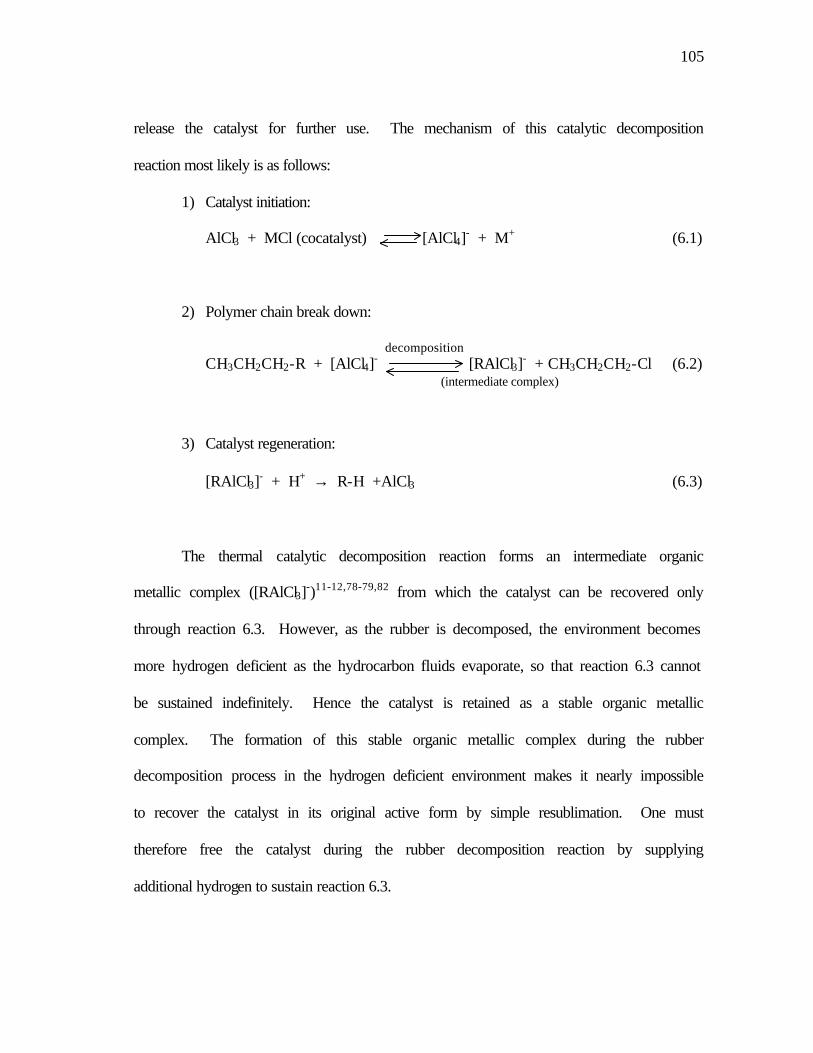
105
release the catalyst for further use. The mechanism of this catalytic decomposition
reaction most likely is as follows:
1) Catalyst initiation:
AlCl3 + MCl (cocatalyst) [AlCl4]- + M+ (6.1)
2) Polymer chain break down:
decomposition CH3CH2CH2-R + [AlCl4]- [RAlCl3]- + CH3CH2CH2-Cl (6.2) (intermediate complex)
3) Catalyst regeneration:
[RAlCl3]- + H+ → R-H +AlCl3 (6.3)
The thermal catalytic decomposition reaction forms an intermediate organic
metallic complex ([RAlCl3]-)11-12,78-79,82 from which the catalyst can be recovered only
through reaction 6.3. However, as the rubber is decomposed, the environment becomes
more hydrogen deficient as the hydrocarbon fluids evaporate, so that reaction 6.3 cannot
be sustained indefinitely. Hence the catalyst is retained as a stable organic metallic
complex. The formation of this stable organic metallic complex during the rubber
decomposition process in the hydrogen deficient environment makes it nearly impossible
to recover the catalyst in its original active form by simple resublimation. One must
therefore free the catalyst during the rubber decomposition reaction by supplying
additional hydrogen to sustain reaction 6.3.

106
AlCl3 is used traditionally as a Friedel-Craft catalyst in alkylation and
isomerization reactions. As these reactions progress, the catalyst also degrades to a less
active state and forms a separate sludge phase. Methods directed to the recovery of
AlCl3 from this sludge have been proposed.81,106 A recent U.S. Patent106 claims a 100%
recovery of AlCl3 catalyst by hydrogenation of the sludge at low temperature (150 oC)
and high pressure (10.44 MPa) with metallic aluminum as a promotion agent.
The investigation of this hydrogenation reaction and hence the catalyst recovery
is not possible with our current experimental equipment. We have thus not verified
whether the catalyst can be recovered completely from the organometallic complex
through hydrogenation. This issue must be resolved during additional studies. The
small amounts of catalyst collected by evaporation and condensation react readily upon
contact with tire rubber compounds in a small-scale glass reactor, indicating that the
activity is not degraded by evaporation.
Finally, no phase separation between the residue and the catalyst was observed
when using pure AlCl3 as the catalyst. However, employing an appropriate second salt
resulted in a homogenous molten liquid phase, which formed at relatively low
temperatures. The dual salt system also appears to form a liquid + solid slurry that
would allow the catalyst to be separated from the reaction residue using on-line
ultrafiltration.

107
CHAPTER VII
CONCLUSIONS AND RECOMMENDATIONS
Thermal catalytic decomposition of used tire rubber has several advantages over
other tire recycling methods in that it is both environmentally benign and economically
viable. The rubber portion of used tires can be converted by thermocatalytic
decomposition into valuable hydrocarbon products and the carbon black filler is
recovered. The economics of this process depends strongly upon the commercial value
of the recovered carbon black and the ability to recover and reuse the catalysts employed
in the process.
The carbon black recovered from this decomposition process is potentially
suitable for a number of applications. The structure and surface morphology of the
recovered carbon black resemble that of commercial carbon black with only slightly
changes. In general, the recovered products possess qualities comparable to or even
better than commercial grade carbon black N660. However, a significant amount of
hydrocarbon oil is present on the recovered carbon black surface and it may deactivate
part of the active sites on the carbon black surface. These oil compounds, which
generally are heavy aromatics and unsaturated cyclic hydrocarbons, can be removed
partially by vacuum thermal treatment. Reducing this oil content should increase the
surface area of the carbon black particles as well as improve the market value and the
range of applications of the recovered carbon black products. An effective post-

108
treatment procedure also will also increase the yield of valuable hydrocarbon products,
and hence the overall economics of the process.
The molten salt catalyst effectively catalyzes the tire rubber decomposition
reaction in both the vapor and liquid phases. However, AlCl3 forms a stable
organometallic complex with the hydrocarbon material produced during the
decomposition process in a hydrogen deficient environment. The result is that it is
nearly impossible to recover the catalyst in its original active form. Therefore, it is
necessary to add hydrogen donor molecules during the reaction, most probably through a
feed gas, to keep the catalytic activity of the catalyst at the required level.
Dual salt systems appear to have significant advantages over pure aluminum
chloride as catalyst. Further studies are needed to determine the nature of the
interrelationship between the primary catalyst and the co-catalyst, and the optimum co-
catalyst. The interaction of the dual salt system with the reaction residue also should be
investigated. It should be possible to separate the dual salt catalyst system from the
reaction residue using on-line ultrafiltration. The feasibility of this molten salt catalyst
recovery method should be studied further both theoretically and experimentally.
109
LITERATURE CITED
(1) Rubber Manufacturers Association, U.S. Scrap Tire Markets 2001, Dec. 2002,
www.rma.org/scraptires.
(2) Clark, C., Meardon, K., Russell, D., Scrap Tire Technology and Markets, U.S.
Environmental Protection Agency, Noyes Data Corporation, Park Ridge, New Jersey,
1993.
(3) Snyder, R. H., Scrap Tires: Disposal and Reuse, Society of Automotive
Engineers, Inc. Warrendale, PA, 1998.
(4) EPA Environmental News, U.S. Environmental Protection Agency,
Washington, DC, Feb. 21, 1994.
(5) New Technology: Waste Tire Recycling Plant Producing High-Performance
Activated Carbon, from JETRO's report No.12, March, 1994,
http://www.p2pays.org/ref/11/10504/html/biblio/htmls/pyh1.htm.
(6) Klingensmith, W. A., Symposium on Recovery and Reuse of Rubber, Rubber
Division, American Chemical Society, Orlando, FL, Oct. 26-29, 1993.
(7) Amari, T., Themelis, N. J., Wernick, I. K., Resource Recovery From Used
Rubber Tires, Published in Resources Policy, 25, 170-188, 1999,
http://www.seas.columbia.edu/earth/rubbertirespaper.htm.
(8) Albright, L. E., Crynes, B. L., and Corcoran, W. H., Pyrolysis: Theory and
Industrial Practice, Academic Press, New York, 1983.
(9) Merchant, A. A., and Petrich, M. A., Pyrolysis of Scrap Tires and Conversion
of Chars to Activated Carbon, AICHE J. 1993, 39, 1370.
(10) Platz, G. M., Depolymerization Method for Resource Recovery from
Polymeric Wastes, U.S. Patent No. 5,264,640, 1993, U.S. Patent No. 5,369215, 1994,
U.S. Patent No. 5,504,267, 1996.
(11) Larsen, J. W., and Chang, B., Conversion of Scrap Tires by Pyrolysis in
Molten Salts, presented at a meeting of the Rubber Division, American Chemical
Society, Minneapolis, MN, April 1976.

110
(12) Ivanova, S. R., Romanko, T. V., Shayekhova, V. G., Sangalov, Y. A., Berlin,
A. A., and Minsker, K. S., Thermocatalytic Degradation of Butyl Rubber in Presence of
Combinations of AlCl3 with Some Metal Chlorides, Polymer Science, U.S.S.R., 1985,
27, 265.
(13) Donnet, J. B., Bansal, R. C., Wang, M. J., Carbon Black, 2nd edition, Marcel
Dekker, Inc., New York, 1993.
(14) Chemical Market Reporter (CMR) online, a publication of the Schnell
Publishing Company, a member of the Reed Elsevier group, http://www.the-innovation-
group.com/ChemProfiles/Carbon%20Black.htm.
(15) Wojtowicz, M. A., Serio, M. A., Pyrolysis of Scrap tires: Can it be
Profitable?, CHEMTECH, 1996, Oct. 48-53.
(16) Rader, C. P., Baldwin, S. D., Cornell, D. D., Sadler, G. D., and Stockel, R. F.,
Plastics, Rubber, and Paper Recycling, A Pragmatic Approach, ACS Symposium Series
609, American Chemical Society, Washington, DC, 1995.
(17) Sharma, V. K., Mincarini, M., Fortuna, F., Cognini, F., and Cornacchia, G.,
Disposal of Waste Tyres for Energy Recovery and Safe Environment---Review, Energy
Convers. Mgmt 1998, 39, No. 5/6, 511-528.
(18) Goodyear, C., US Patent 3,633, 1844.
(19) Holste, J. C. Thermocatalytic Conversion of Tires, Plastics and Other
Organic Materials to Chemical Feedstocks, Private Communication, 1999.
(20) U.S. Environmental Protection Agency, Scrap Tire Technology and Markets,
Pollution Technology Review, No. 211, Noyes Data Corporation, Park Ridge, New
Jersey, 1993.
(21) Granger, J. E. and Clark, G. A., Fuel Characterization of Coal/Shredded Tire
Blends, Proceedings of the Electric Power Research Institute (EPRI) Conference on
Waste Tires as a Utility Fuel, San Jose, CA: EPRI, 1991.
(22) Reisman, J. I., Lemieux, P. M., Air Emissions from Scrap Tire Combustion,
EPA, Washington D.C., Oct. 1997.
111
(23) Allred, R. E., Coons, N. C., Finley, D. J., Shoemaker, J. M., Wilder, R. L.,
Wilder, J.D., Large-scale Recycling Process for Scrap Tires and Rubber Products, 32nd
International SAMPE Technical Conference, Boston, MA, Nov. 5-9, 2000.
(24) Rubber Manufacturers Association, Scrap Tires Characteristics,
http://www.rma.org/scrap_tires/scrap_tire_markets/scrap_tire_characteristics/.
(25) Amari, T., Themelis, N. J., Wernick, I. K., Resource Recovery From Used
Rubber Tires, Published in Resources Policy, 25, 170-188, 1999,
http://www.seas.columbia.edu/earth/rubbertirespaper.htm.
(26) Novotny, D. S., Marsh, R. L., Masters, F. C., and Tally, D. N., U.S. Patent
No. 4,104,205, Aug. 1, 1978.
(27) Fix, S .R., Microwave Devulcanization of Rubber, Elastomerics, 1980, 112,
No. 6, 38-40.
(28) Tukachinsky, A., Schworm, D., Isayev, A. I., Devulcanization of Waste Tire
Rubber by Powerful Ultrasound, Rubber Chem. Tech., 1996, 69: (1) 104-114.
(29) Isayev, A. I., Chen, J., Tukachinsky, A., Novel Ultrasound Technology for
Devulcanization of Waste Rubbers, Rubber Chem. Tech., 1995, 68: 267-280.
(30) Sangdo, P., Earnest, F. G., Statistical Study of the Liquefaction of Used
Rubber Tyre in Supercritical Water, Fuel, 1997, 76, No. 11, 999-1003.
(31) Chen, D. T., Perman, C. A., Riechert, M. E., Hoven, J., Depolymerization of
Tire and Natural Rubber Using Supercritical Fluids, Journal of Hazardorus Materials,
1995, 44, 53-60.
(32) Chambers, C., Larsen, J. W., Li, W., and Wlesen, B., Polymer Waste
Reclamation by Pyrolysis in Molten Salts, Ind. Eng. Chem. Process Des. Dev., 1984, 23,
648-654.
(33) Kenney, C. N., Molten Salt Catalysis of Gas Reactions, Catal. Rev. Sci. Eng.
1975, 11, 197.
(34) Zielke, C. W., Struck, R. T., Gorin, E., Fluidized Combustion Process for
Regeneration of Spent Zinc Chloride Catalysts, Ind. Eng. Chem. Process Des. Dev.,
1969, 8, 552.

112
(35) Zielke, C. W., Klunder, E. B., Maskew, J. T., Struck, R. T., Gorin, E.,
Continuous Hydroliquefaction of Subbituminous Coal in Molten Zinc Chloride, Ind.
Eng. Chem. Process Des. Dev., 1980, 19, 85.
(36) Green, C. R., Biasca, F. E., Pell, M., Struck, R. T., Zielke, C. W., Gasoline
from Coal via Molten Zinc Chloride Hydrocracking, Coal Processing Technology,
1980, 6, 102.
(37) Collin, G., Coal Tar Hydrocarbons: Relations Between Properties and Use,
Erdoel & Kohle, Erdgas, Petrochemie, 1979, 32, 512.
(38) Bhowmick, A. K., Hall, M. M., Benarey, H. A., Rubber Products
Manufacturing Technology, Marcel Dekker, Inc. New York, 1994.
(39) Franta, I., Elastomers and Rubber Compounding Materials, Elsevier, New
York, 1989.
(40) ASTM D 1566-88b, 1989 Annual Book of ASTM Standards, ASTM, West
Conshohocken, PA, Vol. 09, 01, P293.
(41) Barlow, F. W., Rubber Compounding, Principles, Materials, and Techniques,
2nd edition, Marcel Dekker Inc., New York, 1993.
(42) Rubber Statistical Bulletin, International Rubber Study Group, September
2003, http://www.rubberstudy.com/statistics.aspx.
(43) Morton, M., Rubber Technology, 3rd edition, Van Nostrand Reinhold Co.,
New York, 1987.
(44) Wake, W. C., Tidd, B. K., Loadman, M. J. R., Analysis of Rubber and
Rubber-like Polymers, 3rd edition, Applied Science, New York, 1983.
(45) Goodyear, C., U.S. Patent 3,633, 1844; Gum Elastic, New Haven, 1855.
(46) Alliger, G., and Sjothun, I. J., Vulcanization of Elastomers, Van Nostrand
Reinhold Company, New York, 1964.
(47) Mark, J. E., Erman, B., and Eirich, F. R., Science and Technology of Rubber,
Academic Press, New York, 1994.
(48) Saville, B., and Watson, A. A., Structural Characterization of Sulfur-
vulcanized Rubber Networks, Rubber Chem. Technol., 1967, 40, 100.

113
(49) Morita, E., S-N Compounds as Delayed Action Chemicals in Vulcanization,
Rubber Chem. Technol., 1980, 53, 393.
(50) Boonstra, B. B., Cochrane, H., and Dannenberg, E., Reinforcement of
silicone rubber by particulate silica, Rubber Chem. Technol., 1975, 48, 558.
(51) Payne, A. R., in Reinforcement of Elastomers, edited by Kraus, G., Wiley
Intersci., New York, 1965.
(52) Stacy, C. J., Johnson, P. H., Kraus, G., Effect of Carbon Black Structure
Aggregate Size Distribution on Properties of Reinforced Rubber, Rubber Chem.
Technol., 1975, 48, 538.
(53) Kraus, G., Reinforcement of Elastomers by Carbon Black, Fortschritte der
Hochpolymeren-Forschung, 1971, 8, 155.
(54) Johnson, M. P., Locke, R. W., Donnet, J. B., Wang, T. K., Wang, C. C.,
Bertrand, P., Carbon Black and Fullerenes: New Discoveries in Early Formation
Mechanisms and Nucleation, Rubber Chem. Technol., 2000, 73, 875-888.
(55) Darmstadt, H., Cao, N. Z., Pantea, D. M., Roy, C., Summchen, L., Roland,
U., Donnet, J. B., Wang, T. K., Peng, C. H., Donnelly, P. J., Surface Activity and
Chemistry of Thermal Carbon Blacks, Rubber Chem. Technol., 2000, 73, 293-309.
(56) Ullmann’s Encyclopedia of Industrial Chemistry, VCH Verlags Gesellschaft
mbH, Deerfield, FL, 1986, Vol. A5, 140.
(57) ASTM D 1765-99b, 2000 Annual Book of ASTM Standards, ASTM, West
Conshohocken, PA, Vol. 09.01.
(58) Carbon Black, Encyclopedia of Chemical Technology, Wiley, New York,
1993.
(59) ASTM D 3192-97, ASTM D 3191-97, 2000 Annual Book of ASTM
Standards, ASTM, West Conshohocken, PA, Vol. 09.01.
(60) Dannenberg, Eli M., Heckman, F. A., Medalia, A. I., Structure and Particle
Size of Carbon Black. Revue Generale des Caoutchoucs & Plastiques, 1970, 47, 1307.
(61) ASTM D 2414-00, 2000 Annual Book of ASTM Standards, ASTM, West
Conshohocken, PA, Vol. 09.01.

114
(62) ASTM D 3265-99a, 2000 Annual Book of ASTM Standards, ASTM, West
Conshohocken, PA, Vol. 09.01.
(63) Medalia, A. I., Richards, L. W., Tinting Strength of Carbon Black. Journal of
Colloid and Interface Science, 1972, 40, 233-252.
(64) Jordan, M. E., Burbine, W. G., Williams, F. R., Furnace Black as a Filler for
Rubber, Ger. Offen., 1972, 2, 19.
(65) Callan, J. E., Hess, W. M., Scott, C. E., Elastomer Blends: Compatibility and
Relative Response to Fillers, Rubber Chem. Technol., 1971, 44, 814-837.
(66) ASTM D 4820-99, 2000 Annual Book of ASTM Standards, ASTM, West
Conshohocken, PA, Vol. 09.01.
(67) ASTM D 1510-99, 2000 Annual Book of ASTM Standards, ASTM, West
Conshohocken, PA, Vol. 09.01.
(68) ASTM D 3765-99, 2000 Annual Book of ASTM Standards, ASTM, West
Conshohocken, PA, Vol. 09.01.
(69) Emmett, P. H., Brunauer, S., The Use of Low-temperature Van der Waal
Adsorption Isotherms in Determining the Surface Area of Iron Synthetic Ammonia
Catalysts, Journal of the American Chemical Society, 1937, 59, 1553.
(70) Lyon, F., and Burgess, K. A., Encyclopedia of Polymer Science and
Engineering, 2nd edition, Wiley, New York, 1985, 2, 627.
(71) Medalia, A. I., Juengel, R. R., and Collins, J. M., in Developments in Rubber
Technology, edited by Whelan, A., and Lee, K. S., Applied Science Pub. Ltd., Essex,
UK, 1979, p151-181.
(72) Ellul, M. J., Lake, G. J., Thomas, A. G., Strength Properties of Dynamically
Vulcanized Elastomer-polypropylene Blends, Polymeric Materials Science and
Engineering, 1998, 79, 109-110.
(73) Bueche, F., Physical Properties of Polymers, Wiley, New York, 1982.
(74) Williams, F. R., Jordan, M. E., Dannenberg, E. M., Effects of the Chemical
and Physical Properties of Carbon Black on its Performance in Polyethylene, Journal of
Applied Polymer Science, 1965, 9, 861-886.
115
(75) World Carbon Black To 2004, Freedonia Group Report, Apr. 2001,
http://freedonia.ecnext.com/coms2/summary__0001_000736_000000_000000_0001_1.
(76) Cooper, J. F., Private Communication, Proceedings of the Seventh Annual
Diamond Research Corporation Toner & Developer Industry Conference, Santa
Barbara, CA, 1990.
(77) Sundermayer, W., Fused Salts and Their Use as Reaction Media, lectures on
the International Congress for Pure and Applied Chemistry, London, July 15th, 1963.
(78) Cotton, F. A., and Wilkinson, G., Advanced Inorganic Chemistry – A
Comprehensive Text, 4th edition, p330-351, Wiley & Sons, New York, 1980.
(79) Thomas, C. A., Anhydrous Aluminum Chloride in Organic Chemistry,
Reinhold Publishing Corporation, New York, 1941.
(80) 1991 Kirk-Othmer Encyclopedia of Chemical Technology, 4th, edition,
Wiley, New York, 2, 281-284, 1991.
(81) Messina, Giuseppe, Olah, Andrew, G., Moraglia, Riccardo, Process for the
Recovery of Aluminum Trichloride, U.S. Patent No. 4,017,584, April 1977.
(82) Olah, G. A., Friedel-Crafts Chemistry, John Wiley & Sons, Inc., New York,
1973.
(83) Hille, J., Durrwachter, W., Behavior of Molten Fluxes for the Hot-dipping
Process in Zinc, Tin, and Lead, Intern. Conf. Hot Dip Galvanizing, 5th, Benelux,
Germany, 1959.
(84) Publication Release, Witco Corporation, New York, 1990.
(85) Verbeek, W., Sundermeyer, W., Preparation of Fluoromethane in Molten
Fluorides, Angew. Chem., Intern. Ed. (Engl.), 1966, 5, 314.
(86) Kendall, J., Crittenden, E. D., The Separation of Isotopes, Proc. Nat. Acad.
Sci., 1923, 9, 75.
(87) Sangalov, Yu. A., Minsker, K. S., Berlin, Al. Al., and Prochukhan, Yu. A.,
The Cationic Degradation of Polyisobutylene, Polymer Science U.S.S.R., 1983, 25, 7,
1676-1684.

116
(88) Berlin, Al. Al., Minsker, K. S., Sangalov, Yu. A., and Prochukhan, Yu. A.,
Kinetic Features of the Cationic Degradation of Polyisobutylene, Polymer Science
U.S.S.R., 1983, 25, 7, 1684-1694.
(89) Kolomnikova, G. D., Kalinkin, M. I., Makhova, I. V., Parnes, Z. N., and
Kursanov, D. N., Izv. Akad. Nauk SSSR, Ser. Khim., 1886, 19, 822.
(90) Duvenhage, D. J., and Holste, J. C., Private Communication, 1995.
(91) Woodrow, P. T., Design of a Bench-scale Apparatus for Processing Carbon
Black Derived from Scrap Tires, MS. Thesis, Texas A & M University, August 1996.
(92) Platz, G. M., Holste, J. C., and Duvenhage, D. J., Resource Recovery of
Waste Organic Chemicals by Thermal Catalytic Conversion, U.S. Patent No. 6,683,227,
January, 2004.
(93) Qin, F, Thermocatalytic Decomposition of Vulcanized Rubber, Ph.D.
Dissertation, Texas A&M University, May 2004.
(94) Beattie, I. R., Blayden, H. E., Ogden, J. S., The Molecular Shape of
Monomeric Aluminium Trichloride, J. Chem. Phys., 1976, 64, 909-910.
(95) Shirk, J. S., and Shirk, A. E., The Spectrum and Structure of AlCl3”, J. Chem.
Phys., 1976, 64, 910.
(96) ASTM D 1511-98, 2000 Annual Book of ASTM Standards, ASTM, West
Conshohocken, PA, Vol. 09.01.
(97) ASTM D 1514-99, 2000 Annual Book of ASTM Standards, ASTM, West
Conshohocken, PA, Vol. 09.01.
(98) MSDS Alloy% Composition – Carbon Steel,
http://www.capitolcamco.com/MSDS/MSDS_I_CarbonSteel.htm.
(99) Chaala, A., Darmstadt, H., Roy, C., Acid-base Method for the
Demineralization of Pyrolytic Carbon Black, Fuel Processing Technology, 1996, 46, 1-
15.
(100) Earnest, C. M., Compositional Analysis by Thermogravimetry, American
Society for Testing and Materials, Philadelphia, PA., 1988.

117
(101) ASTM D 1506-99, 2000 Annual Book of ASTM Standards, ASTM, West
Conshohocken, PA, Vol. 09.01.
(102) NIST Chemistry WebBook, http://webbook.nist.gov/chemistry.
(103) Shindo, D., Oikawa, T., Analytical Electron Microscopy for Materials
Science, Springer-Verlag, Tokyo, 2002.
(104) ASTM D 3053-99, 2000 Annual Book of ASTM Standards, ASTM, West
Conshohocken, PA, Vol. 09.01.
(105) Viola, J. T., Seegmiller, D. W., Fannin, A. A. Jr., King, L. A., Vapor Pressure
of Aluminum Chloride Systems. 1. Vapor Pressure and Triple Point of Pure Aluminum
Chloride, Journal of Chemical and Engineering Data, 1977, 22, No. 4, 367.
(106) Doane, Elliott, P., Low, Jim Yuen-Fong, Sherman, Larry G, Yuill, William,
A., Aluminum Promoted Hydrogenation of Alkylation Sludge for Aluminum Chloride
Recovery, U.S. Patent No. 6,004,519, Dec. 1999.

118
APPENDIX A
ELEMENTAL COMPOSITION OF
CARBON BLACKS --- ANALYZED BY EDX

119
N220
N330

120
N660
III-02B

121
III-03A
III-04

122
III-06
III-07

123
III-09
III-10

124
III-11
III-13

125
APPENDIX B
MICROGRAPHS OF CARBON BLACK TAKEN BY TEM

126
N220 X50K N220 X100K
N330 X50K N330 X100K
Figure B-1 Commercial carbon black N220 – magnified 50,000 and 100,000 times respectively.
Figure B-2 Commercial carbon black N330 – magnified 50,000 and 100,000 times respectively.

127
N660 X50K N660 X100K
X50K X100K
Figure B-3 Commercial carbon black N660 – magnified 50,000 and 100,000 times respectively.
Figure B-4 Carbon black recovered from Run III-02B – magnified 50,000 and 100,000 times respectively.

128
X50K X100K
X50K X100K
Figure B-5 Carbon black recovered from Run III-03A – magnified 50,000 and 100,000 times respectively.
Figure B-6 Carbon black recovered from Run III-04 – magnified 50,000 and 100,000 times respectively.

129
X50K X100K
X50K X100K
Figure B-7 Carbon black recovered from Run III-06 – magnified 50,000 and 100,000 times respectively.
Figure B-8 Carbon black recovered from Run III-07 – magnified 50,000 and 100,000 times respectively.

130
X50K X100K
X50K X100K
Figure B-9 Carbon black recovered from Run III-09 – magnified 50,000 and 100,000 times respectively.
Figure B-10 Carbon black recovered from Run III-10 – magnified 50,000 and 100,000 times respectively.

131
X50K X100K
X50K X100K
Figure B-11 Carbon black recovered from Run III-11 – magnified 50,000 and 100,000 times respectively.
Figure B-12 Carbon black recovered from Run III-13 – magnified 50,000 and 100,000 times respectively.

132
X50K X100K
X50K X100K Figure B-14 Recovered carbon black sample: III-03A (degassed)– magnified
50,000 and 100,000 times respectively.
Figure B-13 Recovered carbon black sample: III-02B (degassed)– magnified 50,000 and 100,000 times respectively.

133
X50K X100K
Figure B-15 Recovered carbon black sample: III-09 (degassed)– magnified 50,000 and 100,000 times respectively.

134
VITA
Lan Liang was born in Wuwei, Gansui province, P.R. China on June 11, 1973.
She graduated from Jining No. 1 High School in Jining, Shangdong province, China, in
July of 1991. In July of 1995, she received a B.S. degree in Chemical Engineering from
Dalian University of Technology, China. Upon graduation, she continued her study at
Tianjin University as a graduate student and a research assistant as well. In August of
1999, she enrolled in the Ph.D. program in the Chemical Engineering Department of
Texas A&M University. She can be reached through her father, Mr. Dongzheng Liang,
at 173 Taibailou West Road, Jining city, Shangdong Province, 272121, P.R.China.