record of decision - us environmental protection agency · 6.0 current and future land and resource...
TRANSCRIPT

RECORD OF DECISION
WEST LAKE LANDFILL SITEBRIDGETON, MISSOURI
OPERABLE UNIT 1
May 2008
Prepared byU.S. Environmental Protection Agency
Region 7Kansas City, Kansas
30009960
illMllSuperfund
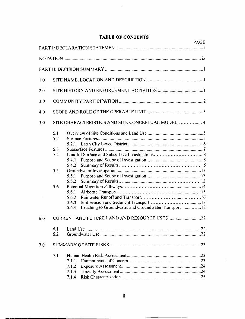
TABLE OF CONTENTSPAGE
PART I: DECLARATION STATEMENT i
NOTATION ix
PART II: DECISION SUMMARY 1
1.0 SITE NAME, LOCATION AND DESCRIPTION 1
2.0 SITE HISTORY AND ENFORCEMENT ACTIVITIES 1
3.0 COMMUNITY PARTICIPATION 2
4.0 SCOPE AND ROLE OF THE OPERABLE UNIT 3
5.0 SITE CHARACTERISTICS AND SITE CONCEPTUAL MODEL 4
5.1 Overview of Site Conditions and Land Use 55.2 Surface Features 5
5.2.1 Earth City Levee District 65.3 Subsurface Features 75.4 Landfill Surface and Subsurface Investigations 8
5.4.1 Purpose and Scope of Investigation 85.4.2 Summary of Results 9
5.5 Groundwater Investigation 135.5.1 Purpose and Scope of Investigation 135.5.2 Summary of Results 13
5.6 Potential Migration Pathways 145.6.1 Airborne Transport 155.6.2 Rainwater Runoff and Transport 165.6.3 Soil Erosion and Sediment Transport 1 75.6.4 Leaching to Groundwater and Groundwater Transport 18
6.0 CURRENT AND FUTURE LAND AND RESOURCE USES 22
6.1 Land Use 226.2 Groundwater Use 22
7.0 SUMMARY OF SITE RISKS 23
7.1 Human Health Risk Assessment 237.1.1 Contaminants of Concern 237.1.2 Exposure Assessment 247.1.3 Toxicity Assessment 247.1.4 Risk Characterization 25

TABLE OF CONTENTS (CONT.)PAGE
7.1.5 Uncertainties 26
7.2 Ecological Risk Assessment 27
8.0 REMEDIAL ACTION OBJECTIVES 28
8.1 Presumptive Remedy Approach for CERCLA Landfills 298.2 Remedial Action Objectives for Areas 1 and 2 308.3 Remedial Action Objectives for Buffer Zone/Crossroad Property 30
9.0 DESCRIPTION OF REMEDIAL ALTERNATIVES 30
9.1 Areas 1 and 2 319.1.1 Alternative LI: No Action 319.1.2 Alternative L2: Cover Repair and Maintenance ...329.1.3 Alternative L3: Soil Cover to Address Gamma .329.1.4 Alternative L4: Subtitle D Cover (2% Slope).... 329.1.5 Alternative L5: Subtitle D Cover (5% Slope) 339.1.6 Alternative L6: Excavation and Subtitle D Cover 34
9.2 Buffer Zone/Crossroad Property ..359.2.1 Alternative Fl: No Action 369.2.2 Alternative F2: Institutional and Access Controls : 369.2.3 Alternative F3: Capping and Institutional Controls 369.2.4 Alternative F4: Soil Excavation and Consolidation 37
10.0 SUMMARY OF COMPARATIVE ANALYSIS OF ALTERNATIVES 37
10.1 Overall Protection of Human Health and the Environment 3710.2 Compliance with ARARs 3810.3 Long-Term Effectiveness and Permanence 3810.4 Reduction of Toxicity, Mobility, or Volume Through Treatment 3910.5 Short-Term Effectiveness 3910.6 Implementability 3910.7 Cost '. 4010.8 State Acceptance 4110.9 Community Acceptance 42
11.0 PRINCIPAL THREAT WASTES 42
12.0 SELECTED REMEDY 42
12.1 Summary of the Rationale for the Selected Remedy 4212.2 Description of the Selected Remedy 43
12.2.1 Groundwater Monitoring Objectives 45
111

TABLE OF CONTENTS (Cont.)
PAGE
12.2.2 Institutional Controls 4612.2.3 Estimated Remedy Costs 47
12.3 Expected Outcomes of the Selected Remedy 48
13.0 STATUTORY DETERMINATIONS 48
13.1 Protection of Human Health and the Environment 4813.2 Compliance with ARARs 4913.3 Cost Effectiveness 5313.4 Utilization of Permanent Solutions and Alternative Treatment
Technologies to the Maximum Extent Practicable 5313.5 Preference for Treatment as a Principal Element 5313.6 Five-Year Reviews 5313.7 Significant Changes from the Proposed Plan 54
14.0 REFERENCES 55
PART III: RESPONSIVENESS SUMMARY (Under Separate Cover)
IV

FIGURES
1-1 Location of the West Lake Landfill Site 57
1-2 Vicinity Map 58
2-1 Pitchblende Ore Process 59
2-2 Ore Process Residues 60
4-1 Site Layout 61
5-1 Conceptual Model of Migration Pathways 62
5-2 Conceptual Site Model 63
5-3 Soil Boring Locations 64
5-4 Extent of Radionuclide Impacted Materials at the Surface 65
5-5 Extent of Radionuclide Impacted Material in the Subsurface 66
5-6 Occurrences of Perched Water in Areas 1 and 2 67
5-7 Groundwater Monitoring Well Locations 68
5-8 Groundwater and Surface Water Chlorobenzene Results 69
5-9 Groundwater and Surface Water Benzene Results 70
5-10A Groundwater and Surface Water Dissolved Lead Results : 71
5-10B Groundwater and Surface Water Total Lead Results 72
5-11A Groundwater and Surface Water Dissolved Arsenic Results 73
5-1 IB Groundwater and Surface Water Total Arsenic Results.. 74
5-12A Groundwater and Surface Water Dissolved Radium Results..... 75
5-12B Groundwater and Surface Water Total Radium Results 76
12-1 Conceptual Cross-section of the Selected Remedy 77
12-2 Engineered Landfill Cover Conceptual Design 78

12-3 Effect of Cover Thickness on Dose Rates 79
TABLES
i
5-1 Summary of Constituents Detected in Groundwater OU-1 Rl ...81
5-2 Summary of Radionuclide Occurrence in Area 1 Surface Samples 82
5-3 Summary of Radionuclide Occurrence in Area 1 Subsurface Samples 83
5-4 Summary of Radionuclide Occurrence in Area 2 Surface Samples 84
5-5 Summary of Radionuclide Occurrence in Area 2 Subsurface Samples 85
5-6 Summary of Background Radionuclide Levels 86
7-1 Current Exposure Point Concentrations in Area 1 Soil 87V
7-2 Current Exposure Point Concentrations in Area 2 Soil ...88
7-3 Current Exposure Point Concentrations in for the Ford Property Soil 89
7-4 Future Exposure Point Concentrations for Area 1 Soil 90
7-5 Future Exposure Point Concentrations for Area 2 Soil 91
7-6 Future Exposure Point Concentrations for Ford Property Soil .....92
7-7 Future Exposure Point Concentrations in Air 93
7-8 Radiological Carcinogenic Slope Factors 94
7-9 Chemical Carcinogenic Slope Factors 95
7-10 Chemical Reference Doses 96
7-11 Lifetime Cancer Risks for the Landfill Groundskeeper ScenarioArea 1 - Future Conditions 97
7-12 Lifetime Cancer Risks for the Landfill Groundskeeper ScenarioArea 2 -Future Conditions 98
VI

7-13 Lifetime Cancer Risks for the Adjacent Building User ScenarioArea 1 - Future Conditions 99
7-14 Lifetime Cancer Risks for the Adjacent Building User ScenarioArea 2 - Future Conditions 100
7-15 Lifetime Cancer Risks for the Landfill Storage Yard Worker ScenarioArea 1 - Future Conditions 101
7-16 Lifetime Cancer Risks for the Landfill Storage Yard Worker ScenarioArea 2 - Future Conditions 102
7-17 Lifetime Cancer Risks for the Groundkeeper ScenarioFord Property - Future Conditions 103
7-18 Hazard Quotients and Hazard Index for All Future Scenarios 104
7-19 Summary of Risks for Future Receptor Scenarios 105
7-20 Summary of Pathways for Ecological Receptors 106
7-21 Summary of Risk Findings for Plant and Invertebrates 107
7-22 Summary of Risk Findings for Wildlife with Small Home Ranges 108
7-23 Summary of Risk Findings for Wildlife with Large Home Ranges 109
12-1 Capital Cost Estimate for the Selected Remedy 111
vn

ABBREVIATIONS
The following is a list of the abbreviations used in this document:
GENERAL
AEC U.S. Atomic Energy CommissionAOC Administrative Order on ConsentAR Administrative RecordARAR Applicable or Relevant and Appropriate RequirementBRA Baseline Risk AssessmentCERCLA Comprehensive Environmental Response, Compensation, and Liability ActCFR Code of Federal RegulationsCOC Contaminant of ConcernCORPS U.S. Army Corps of EngineersCSR Code of State RegulationsEPA U.S. Environmental Protection AgencyFS Feasibility StudyHI Hazard IndexHQ Hazard QuotientLUST Leaking Underground Storage TankMCL Maximum Contaminant LevelMDNR Missouri Department of Natural ResourcesMECA Missouri Environmental Covenants ActNCP National Oil and Hazardous Substances Pollution Contingency PlanNESHAP National Emission Standards for Hazardous Air PollutantsNPL National Priorities ListO&M Operations and MaintenanceOU Operable UnitPRPs Potentially Responsible PartiesRAO Remedial Action ObjectiveRD Remedial DesignRI Remedial InvestigationRfD Reference DoseROD Record of DecisionSLAPS St. Louis Airport SiteUMTRCA Uranium Mill Tailings Radiation Control Act
vin

CHEMICALS
PCBs Polychlorinated BiphenylsRa-226 Radium-226Rn-222 Radon-222SVOC Semivolatile Organic CompoundTh-232 Thorium-232Th-230 Thorium-230U-238 Uranium-238.U-235 Uranium-235U-234 Uranium-234VOC Volatile Organic Compound
UNITS OF MEASURE
cm Centimeterft\amsl Feet Above Mean Sea Levelm2 Square MeterpCi/g Picocuries per grampCi/1 Picocuries per Literppm Parts per Millionmg/kg Milligrams per Kilogrammg/1 Milligrams per Litersec Secondug/1 Microgram per Literyd3 Cubic Yards
IX

Record of Decision Data Certification Checklist
The following information is included in this Record of Decision. Additional informationis in the Administrative Record file for this Site.
Site Data Chapter
Contaminants of Concern 7.0
Baseline risk represented by the contaminants 7.0
Remedial Action Objectives 8.0
Principal Threats 11.0
Current and reasonably anticipated future land andgroundwater use assumptions 6.0
Potential land and groundwater use that will beavailable after implementation of the remedy „ 6.0 & 12.0
Estimated capital, annual operation andmaintenance, and total present worth costs 12.0
Key factor(s) that led to selecting the remedy 10.0 & 12.0

PARTI. DECLARATION
Site Name and Location
West Lake Landfill SiteOperable Unit 1Bridgeton, MissouriCERCLIS ID Number: MOD079900932
Statement of Basis and Purpose
This Record of Decision (ROD) presents the Selected Remedy for Operable Unit 1 (OU 1)of the West Lake Landfill site (Site) in Bridgeton, Missouri. This remedy was selected inaccordance with the Comprehensive Environmental Response, Compensation, and LiabilityAct, as amended by the Superfund Amendments and Reauthorization Act, and to the extentpracticable, the National Oil and Hazardous Substances Pollution Contingency Plan. Thisdecision is based on information contained in the Administrative Record file for the Site.
The Missouri Department of Natural Resources (MDNR), acting on behalf of the state ofMissouri, accepts the Selected Remedy. See section 10.8 of the Decision Summary forMDNR's statement.
Assessment of the Site
The response action selected in this ROD is necessary to protect the public health orwelfare or the environment from actual or threatened releases of hazardous substances intothe environment.
Description of the Selected Remedy
The Site consists of the Bridgeton Sanitary Landfill (Former Active Sanitary Landfill) andseveral inactive areas with sanitary and demolition fill that were closed prior to stateregulation. Two areas of the Site were radiologically contaminated when soils mixed withuranium ore processing residues were reportedly used as soil cover for municipal refuse inthe landfill operations. The Site is divided into two OUs. OU 1 consists of theradiologically contaminated landfill areas and the area formerly described as the FordProperty, now called the Buffer Zone/Crossroad Property. OU 2 consists of the otherlandfill areas that are not impacted by radionuclide contaminants. The Selected Remedyfor OU 2 is provided in a separate ROD. The Site does not contain principal threat wastes.See section 11.0 of the Decision Summary for an explanation of principal threat wastes.
The major components of the Selected Remedy for OU 1 are as follows:
o Install landfill cover meeting the Missouri closure and post-closure carerequirements for sanitary landfills, including enhancements consistent with thestandards for uranium mill tailing sites, i.e., armoring layer and radon barrier
XI

• Consolidation of radiologically contaminated surface soil from the BufferZone/Crossroad Property to the containment area
• Apply groundwater monitoring and protection standards consistent withrequirements for uranium mill tailing sites and sanitary landfills
• Surface water runoff control
• Gas monitoring and control including radon and decomposition gas as necessary
• Institutional controls to prevent land and resource uses that are inconsistent with aclosed sanitary landfill site containing long-lived radionuclides
• Long-term surveillance and maintenance of the remedy
Statutory Determinations
The Selected Remedy is protective of human health and the environment, complies withfederal and state requirements that are applicable or relevant and appropriate, is costeffective, and utilizes permanent solutions and alternative treatment technologies to themaximum extent practicable.
The remedy for OU 1 does not satisfy the statutory preference for treatment as a principalelement of the remedy. The contaminants are dispersed within large volumes ofheterogeneous municipal refuse and demolition debris; there are no practicable treatmentalternatives, and no principal threat wastes have been identified.
This remedy will result in hazardous substances, pollutants, or contaminants remaining onthe Site above levels that allow for unlimited use and unrestricted exposure; therefore, astatutory review will be conducted within five years after initiation of the remedial actionto ensure the remedy is or will be protective of human health and the environment."
JohnT^f Askew DaRegional Administrator
xn

PART II. DECISION SUMMARY
1.0 SITE NAME, LOCATION, AND DESCRIPTION
The West Lake Landfill Site (Site) is located in Bridgeton, Missouri. The U.S.Environmental Protection Agency (EPA) is the lead agency, and the MissouriDepartment of Natural Resources (MDNR) is the supporting state agency. The EPA IDNumber is MOD079900932.
The Site is on a parcel of approximately 200 acres located in the northwestern portion ofthe St. Louis metropolitan area (Figure 1-1). It is situated approximately one mile northof the intersection of Interstate 70 and Interstate 270 within the limits of the city ofBridgeton in northwestern St. Louis County. The Missouri River lies about two miles tothe north and west of the Site. The Site is bounded on the north by St. Charles RockRoad and on the east by Taussig Road. Old St. Charles Rock Road borders the southernand western portions of the Site. The Earth City Industrial Park is adjacent to the Site onthe west. The Spanish Village residential subdivision is located less than a mile to thesouth (Figure 1-2).
The Site consists of the Bridgeton Sanitary Landfill (Former Active Sanitary Landfill)and several inactive areas with sanitary and demolition fill that have been closed. Theaddress of the Bridgeton Landfill is 13570 St. Charles Rock Road. The Site is dividedinto two operable units (OUs). OU 1 addresses two of the inactive landfill areas that areradiologically contaminated known as Area 1 and Area 2, and the area formerly describedas the Ford Property, now the Buffer Zone/Crossroads Property. This Record of Decision(ROD) provides the Selected Remedy for OU 1. The other landfill areas that are notimpacted by radionuclide contaminants are addressed by OU 2. OU 2 is addressed undera separate ROD.
Other facilities which are not subject to this response action are located on the 200-acreparcel including concrete and asphalt batch plants, a solid waste transfer station, and anautomobile repair shop.
2.0 SITE HISTORY AND ENFORCEMENT ACTIVITIES
The Site was used agriculturally until a limestone quarrying and crushing operation beganin 1939. The quarrying operation continued until 1988 and resulted in two quarry pits.Beginning in the early 1950s, portions of the quarried areas and adjacent areas were usedfor landfilling municipal refuse, industrial solid wastes, and construction/demolitiondebris. These operations were not subject to state permitting because they occurred priorto the formation of MDNR in 1974. Two landfill areas were radiologically contaminatedin 1973 when they received soil mixed with leached barium sulfate residues.
The barium sulfate residues, containing traces of uranium, thorium, and their long-liveddaughter products, were some of the uranium ore processing residues initially stored bythe Atomic Energy Commission (AEC) on a 21.7-acre tract of land in a then undevelopedarea of north St. Louis County, now known as the St. Louis Airport Site (SLAPS), which
1

is part of the St. Louis Formerly Utilized Sites Remedial Action Program managed by theU.S. Army Corps of Engineers (Corps). The radium and lead-bearing residues;—knownas K-65 residues—were stored in drums prior to being relocated to federal facilities inNew York and Ohio.
In 1966 and 1967, the remaining residues from SLAPS were purchased by a privatecompany for mineral recovery and placed in storage at a nearby facility on Latty Avenueunder an AEC license. Most of the residues were shipped to Canon City, Colorado, forreprocessing except for the leached barium sulfate residues, which were the least valuablein terms of mineral content, i.e., most of the uranium and radium was removed inprevious precipitation steps. Reportedly, 8,700 tons of leached barium sulfate residueswere mixed with approximately 39,000 tons of soil and then transported to the Site.According to the landfill operator, the soil was used as cover for municipal refuse inroutine landfill operations. The data collected during the Remedial Investigation (RI) areconsistent with this account. Figure 2-1 is a generalized illustration of the ore processingsteps, and Figure 2-2 identifies the barium sulfate residues that went to the Site.
The quarry pits were used for permitted solid waste landfill operations beginning in 1979.In August 2005, the Bridgeton Sanitary Landfill (Former Active Sanitary Landfill)stopped receiving waste pursuant to an agreement with the city of St. Louis to reduce thepotential for birds to interfere with airport operations.
EPA placed the Site on the Superfund National Priorities List (NPL) in 1990. The NPLis a list of priority sites promulgated pursuant to section 105 of the ComprehensiveEnvironmental Response, Compensation, and Liability Act (CERCLA) of 1980, asamended. The NPL is found in Appendix B of the National Oil and HazardousSubstances Pollution Contingency Plan (NCP).
In 1993, EPA entered into an Administrative Order on Consent (AOC) with thepotentially responsible parties (PRPs) for performance of the OU 1 RI/Feasibility Study(FS). Pursuant to the requirements of that order, the PRPs submitted for EPA's reviewand approval an RI which detailed the findings of extensive sampling and analysis on thearea of OU 1 and the surrounding area. Following the RI, the PRPs submitted for EPA'sreview and approval an FS which evaluated the various remedial alternatives for OU 1consistent with the requirements of the AOC and taking into account the requirements ofCERCLA and the NCP. In addition, the state of Missouri was provided an opportunityfor review and comment on these documents.
3.0 COMMUNITY PARTICIPATION
Public participation activities for the remedy selection process were carried out consistentwith NCP section 300.430(f)(3). The Proposed Plan and the Administrative Record (AR)file—which contains the RI/FS and other supporting documents—were made available tothe public in June 2006. The AR file was placed at Bridgeton Trails Branch of the publiclibrary which is located near the Site. The public notice on the Proposed Plan and publicmeeting was published in Bridgeton/Hazelwood Journal of the St. Louis Post Dispatch.Fact Sheet notices were sent to area residents, elected officials, and the media outlets.

The comment period was opened on June 14, 2006. The first public meeting was held onJune 22, 2006, at the Bridgeton Community Center. At the meeting, EPA provided anoverview of the Site, described the preferred alternatives for both OU 1 and OU 2, andexplained the remedy selection process. Following the presentation, oral comments fromthe public were received.
In response to a request from the city of Bridgeton, the comment period was extended toAugust 14, 2006, and later extended again to October 14, 2006. Following public notice,a second public meeting was held at City Hall on September 14, 2006. All of thecommunity concerns expressed at the first meeting were related to the proposed remedyfor OU 1. Therefore, the presentation at the second meeting was more narrowly focusedto address concerns with the proposed remedy for OU 1 that were identified at the firstmeeting. Following the presentation, oral comments from the public were received.
In response to additional requests, EPA further extended the comment period toDecember 29, 2006. In total, the public comment period was held open for more than sixmonths.
Responding to ongoing community interest, EPA reopened the public comment periodand held a third public meeting on March 27, 2008. This third public comment periodwas closed on April 9, 2008.
Written transcripts were made of all three public meetings and these are contained in theAR file. Responses to comments received at the meeting and to written commentsreceived during the comment period are provided in the Responsiveness Summary, whichis Part III of this ROD.
4.0 SCOPE AND ROLE OF THE RESPONSE ACTION
The Site is divided into the following areas (see Figure 4-1):
« Radiological Area 1 - This area was part of the landfill operations conductedprior to state regulation. Approximately 10 acres are impacted by radionuclides atdepths ranging up to 15 feet. The radionuclides are in soil material that isintermixed with the overall landfill matrix consisting of municipal refuse.
« Radiological Area 2 - This area was also part of the unregulated landfilloperations conducted prior to 1974. Approximately 30 acres are impacted byradionuclides at depths generally ranging to 12 feet, with some localizedoccurrences that are deeper. The radionuclides are in soil material that isintermixed with the overall landfill matrix consisting mostly of construction anddemolition debris.
» Buffer Zone/Crossroad Property - This property—also known as the FordProperty—lies west of Radiological Area 2 and became surficially contaminatedwhen erosion of soil from the landfill berm resulted in transport of radiologicallycontaminated soils from Area 2 onto the adjacent property.

• Closed Demolition Landfill - This area is located on the southeast side ofRadiological Area 2. This landfill received demolition debris. It received none ofthe radiologically contaminated soil. It operated under permit with the state andwas closed in 1995.
• Inactive Sanitary Landfill - This landfill is located south of Radiological Area 2and was part of the unregulated landfill operations conducted prior to 1974. Thelandfill contains sanitary wastes and a variety of other solid wastes and demolitiondebris. It received none of the radiologically contaminated soil.
• Former Active Sanitary Landfill - This municipal solid waste landfill—known asthe Bridgeton Landfill—is located on the south and east portions of the Site. Thelandfill is subject to a state permit issued in 1974. This landfill received none ofthe radiologically contaminated soil. This landfill ceased operation in 2005.
The Site has been divided into two OUs. OU 1 consists of Radiological Area 1 andRadiological Area 2 (Areas 1 and.2) and the Buffer Zone/Crossroad Property. This RODprovides the Selected Remedy for OU 1. OU 2 consists of the other landfill areas that arenot impacted by radionuclides, i.e., the Closed Demolition Landfill, the Inactive SanitaryLandfill, and the Former Active Sanitary Landfill. The Selected Remedy for OU 2 isprovided in a separate ROD. The OU 1 and OU 2 RODs provided the final remedies forboth source control and groundwater and complete the CERCLA decision-making for theSite. The specific remedial action objectives (RAOs) are described in Section 8 of thisROD.
Section 12 of this ROD identifies the performance standards and environmentalrequirements for the Selected Remedy. This ROD will be followed by a RemedialDesign and Remedial Action (RD/RA) process to develop specific standards forconstruction, monitoring, and maintenance.
5.0 Site Characteristics and Site Conceptual Model
This section presents a summary of the findings of the RI investigations. Sections 5.1through 5.5 provide an overview of the Site's conditions, the investigations that wereundertaken, and the nature and extent of contamination. Section 5.6 presents the Siteconceptual model through discussion of the actual and potential pathways for migrationand/or exposure to the Site's contaminants. Illustrations of the Site conceptual model aredepicted in Figures 5-1 and 5-2. Both radionuclide and nonradionuclide contaminantshave been investigated.
The following pathways have been investigated:
o Airborne transport of radon gas and fugitive dust
o Rainwater runoff transport of dissolved or suspended contaminants

• Erosion and transport of contaminated soils
• Leaching of contaminants to the underlying alluvial groundwater
5.1 Overview of Site Conditions and Land Use
The Site is located within the western portion of the St. Louis metropolitan area on theeast side of the Missouri River. The landfill is situated approximately one mile north ofthe intersection of Interstate 70 and Interstate 270 within the city limits of the city ofBridgeton in northwestern St. Louis County. St. Charles Rock Road (State Highway 180)borders the landfill on the north. Taussig Road and agricultural land lie southeast of thelandfill. Old St. Charles Rock Road, along with undeveloped land, borders the southernand western portions of the landfill (Figure 1-2).
The Site is an approximately 200-acre parcel containing multiple facilities. The primaryfacility—the Bridgeton Landfill (formerly known as the Laidlaw Landfill)—has anaddress of 13570 St. Charles Rock Road, St. Louis County, Missouri. The BridgetonLandfill, referred to herein as the Former Active Sanitary Landfill, stopped receivingwaste in 2005 and is now in post-closure status. Other facilities on the Site that are notthe subject of the CERCLA action include the concrete and asphalt batch plants, anautomotive repair shop, and a waste transfer station. The Site's layout is shown in Figure4-1.
Land use in the area surrounding the landfill is commercial and industrial. Deedrestrictions have been recorded against the entire Site to prevent residential developmentor groundwater use from occurring at the landfill. Additional deed restrictions have beenrecorded against Areas 1 and 2 to prevent construction of buildings or utility excavationsin these areas. The southernmost portion of the landfill property is permitted for activesanitary landfill operations (Permit No. 118912).
The property to the north of the landfill across St. Charles Rock Road is moderatelydeveloped with commercial, retail, and manufacturing operations. The Earth CityIndustrial Park is located adjacent to the landfill on the west, across Old St. Charles RockRoad. The nearest residential development, Spanish Village, is located to the south of thelandfill near the intersection of St. Charles Rock Road and Interstate 270 approximately.75 mile from Area 1 and 1 mile from Area 2. Mixed commercial, retail, manufacturing,and single-family residential uses are present to the southeast of the landfill.
5.2 Surface Features
The Site is situated on the eastern edge of the Missouri River flood plain approximatelytwo miles east of the river. The river is separated from the area of the Site by a leveesystem.

Ground elevations at the Site range from approximately 450 to 500 feet; however, thetopography of the Site area has been significantly altered by quarry activities in theeastern portion of the landfill and by placement of mine spoils and landfill materials inthe eastern and western portion of the landfill.
Area 1 is situated on the north and western slopes of a topographic high within thelandfill. Ground surface elevation in Area 1 varies from 490 feet on the south to 452 feetat the roadway near the landfill property entrance.
Area 2 is situated between a topographic high of landfilled materials on the south andeast and the Buffer Zone and Crossroad Properties (former Ford Property) on the west.The highest topographic level in Area 2 is about 500 feet on the southwest side of Area 2sloping to approximately 470 feet near the top of the landfill berm along the south side ofthe Ford Property. The upper surface of the berm along the western edge of Area 2 islocated approximately 20 to 30 feet above the adjacent Ford Property and approximately30 to 40 feet higher than the water surface in the flood control channel located to thesouthwest of Area 2. A berm on the northern portions of Area 2 controls runoff to theadjacent properties.
On the north side of Area 2 is the property referred to as the Buffer Zone/CrossroadProperty (called the Ford Property in the RI). This property was previously owned byFord Motor Credit, Inc. (Ford). Prior to 1998, Ford subdivided and sold all of itsproperty in this area. The majority of the Ford Property was sold to Crossroad PropertiesLLC and has been developed into the Crossroad Industrial Park. .Ford retained the 1.78acres immediately adjacent to the western portion of the northern boundary of Area 2referred to as the Buffer Zone. The ownership of the Buffer Zone was subsequentlyacquired by Rock Road Industries, Inc. (Rock Road) on behalf of the landfill owner.
5.2.1 Earth City Levee District
The Site borders the Earth City Levee District to the east, with the northwestern edge ofthe Site located about one and one third mile from the Missouri River. The Earth CityLevee District is fully developed with business and industrial parks. The 1,891-acreLevee District is protected on three sides with the main levee running 2.6 miles along theeastern bank of the Missouri River. The levee system is designed to exceed the 500-yearflood level and ranges from 462.03 feet above mean sea level (ft/amsl) at the south end to459.34 ft/amsl at the north end. The 500-year flood elevations at these locations are459.03 ft/amsl and 452.15 ft/amsl, respectively. Assuming a 500-year flood, theMissouri River would be three to seven feet below the top of the Earth City levee.
Landfilling at the Site has significantly raised the elevation of Areas 1 and 2 above thelevel of the former flood plain. The top elevation of the Area 2 berm is approximately 20feet above the projected flood elevations of about 453 feet within the levee system alongthe river. Flooding of areas adjacent to the landfill, i.e., areas outside of the levee system,would only occur as a result of a failure of the levee system. Spreading of floodwatersinto areas outside of the levee system would result in lower flood elevations than thoseprojected to occur within the levee system. Therefore, the actual elevations of any

floodwaters that may extend into areas adjacent to the landfill would be less than 453feet. The result would be no more than a foot or two of water at the northwestern toe ofthe landfill. Four major flood events have occurred since the levee was completed in1972. including the record level flood of August 1993 when the Missouri River crested at14.6 feet above flood stage and remained above flood level for about 110 days. Theflood control system functioned successfully in each case.
According to information provided on the Earth City Levee District web site, the LeveeDistrict has:
developed a comprehensive and ongoing maintenance program whereby theentire levee system, relief wells, pump station and other mechanical andelectrical systems are inspected at least annually by qualified independentcontractors. The Corps inspects the levee and pump station normally on anannual basis. The District's levee and the pump station have qualified forparticipation in the Corp's rehabilitation assistance program for flood controlprojects (e.g. Public Law 84-99.) As a result of such participation, theCorps will pay 80 percent of the construction costs incurred in connectionwith rehabilitation of the levee or pump station resulting from flooding.Costs such as dirt are not covered by the Corps' assistance program.
5.3 Subsurface Features
The geology of the landfill area consists of Paleozoic-age sedimentary rocks overlyingPre-Cambrian-age igneous and metamorphic rocks. The Paleozoic bedrock is overlain byunconsolidated alluvial and loess deposits of recent (Holocene) age.
Alluvial deposits of varying thickness are present beneath Areas 1 and 2. The landfilldebris varies-in thickness from 5 to 56 feet in Areas 1 and 2, with an average thickness ofapproximately 30 feet in Area 2.. The underlying alluvium increases in thickness fromeast to west beneath Area 1. The alluvial thickness beneath the southeastern portion ofArea 1 is less than 5 feet (bottom elevation of 420 ft/amsl) while the thickness along thenorthwestern edge of Area 1 is approximately 80 feet (bottom elevation of 370 ft/amsl).The thickness of the alluvial deposits beneath Area 2 is fairly uniform at approximately100 feet (bottom elevations of 335 ft/amsl).
During the RI investigations, groundwater was generally encountered in the underlyingalluvium near or immediately below the base of the landfill debris. Isolated bodies ofperched water were encountered in 2 of the 24 soil borings drilled in Areas 1 arid 6 of the40 borings drilled in Area 2 as part of the RI field investigations. The perched watergenerally occurs in small isolated units at depths varying from 5 to 30 feet below groundsurface.
Monthly groundwater levels measured in various landfill wells indicate that only a verysmall amount of relief (less than a foot) exists in the natural alluvial water table surface.The regional direction of groundwater flow is northerly within the Missouri River alluvial

valley, parallel or subparallel to the river alignment. However, theleachate collectionsystem for the Former Active Sanitary Landfill creates a localized cone of depression thatextends across the eastern half of the Site and includes the water table underlying Area 1.The approximate extent of the inward hydraulic gradient and the generalized flowdirection is shown on the maps showing the groundwater sampling results (Figures 5-8through 5-12).
Vertical hydraulic gradients were calculated using piezometer clusters. The verticalhydraulic gradients for the shallow alluvium to intermediate or deep alluvium and fordeep alluvium to shallow bedrock are very small and vary from slightly downward toslightly upward.
5.4 Landfill Surface and Subsurface Investigations
This section describes the surface and subsurface investigation activities in the fillmaterial including surface geophysical investigations, perched water investigation,landfill gas surveys, borehole drilling, soil sample collection and chemical analyses,downhole gamma logging, and geotechnical sampling and testing.
5.4.1 Purpose and Scope of Investigation
The surface and subsurface soil and perched water investigation activities werecompleted to characterize the distribution and extent of radioactive and hazardousnonradioactive constituents within the landfill mass, including the various cover soils andpotential perched water occurrences in Areas 1 and 2.
Investigations of the landfill soils and perched water included the following:
« Pre-screening of each soil boring location within the landfill for potential largemetal obstacles and methane concentrations
o Drilling of 20 borings in Area 1 and 40 borings in Area 2 (Figure 5-3), includingpre-drilling of all planed monitoring wells to be completed through areasunderlain by landfill refuse
« Collection of soil samples from all of the soil borings, generally at five-foot depthintervals and performance of radiological and chemical analyses on selected soilsamples from the various soil borings
• Collection of samples from four background locations potentially representativeof daily cover materials and performance of radiological and chemical analyses
• Downhole radiological logging of all of the newly drilled soil borings and allexisting monitoring wells and cased soil borings remaining from prior Siteinvestigations that could be located

• Collection of selected perched water samples encountered during the soil boringactivities
• Collection and laboratory testing for selected geotechnical properties of four soilsamples obtained from the landfill slope at the northern edge of Area 2 above theformer Ford Property.
5.4.2 Summary of Results
Significant observations with respect to landfill setting, radiological constituents,nonradiological constituents, and perched water based upon the data collected aredescribed in the following subsections.
Landfill Setting
Based on the data collected, the following observations were made regarding the generalSite geologic and hydrogeologic conditions and the nature and configuration of thelandfill debris:
• The thickness of the landfill materials varies from 20 to 56 feet in Area 1, and 11to 45 feet in Area 2
• Loess (silt, clay, and fine sand) materials were used to cover the landfill debris inAreas 1 and 2
« Isolated occurrences of perched water were found to be present within the landfilldebris and where present, perched water was found to be of very limited extent
o Regional (continuous) groundwater generally occurs in the unconsolidatedalluvial deposits present below the base of the landfill debris
Radiological Constituents
Based on the data collected, the following observations were made regarding theoccurrences of radiological constituents within the landfill debris: (1) Radionuclides aredispersed in landfill deposits in Areas 1 and 2. Radiological constituents occur in soilmaterials that are intermixed with and interspersed in the overall matrix of landfilledrefuse, debris, fill materials, and unimpacted soil. In some portions of Areas 1 and 2,radiologically impacted materials are present at or near the surface; however, the majorityof the radiological occurrences are in the subsurface. (2) The primary radionuclidesdetected at levels above background concentrations at OU 1 are part of the uranium-238(U-238) and uranium-235 (U-235) decay series. Isotopes from the thorium-232 (Th-232)decay series are also present above background levels but to a lesser degree. Theradionuclides derive from ore processing residues with an elevated ratio of Th-230. Thehigh relative concentration of Th-230 resulted from ore processing designed to separateout uranium and radium, leaving thorium in the residue (by-product). See Tables 5-2

through 5-6 for a summary of radionuclide occurrences in Areas 1 and 2 and the resultsof background sampling.
Radiological Occurrences at Area 1
Radionuclides are present in the upper six inches (15 centimeter [cm]) at levels above theUranium Mill Tailings Radiation Control Act (UMTRCA3) standard for surface soil (5pCi/g over background) over approximately 50,700 square feet (1.16 acres) (Figure 5-4).Approximately 194,000 square feet (4.45 acres) have radionuclides present in thesubsurface at depths ranging up to seven feet, with localized intervals present to depths of15 feet (Figure 5-5). Subsurface occurrences of radionuclides are present in soil materialthat is intermixed with the overall landfill matrix of refuse, debris, and fill materials. Thetotal volume of radiologically impacted materials and associated landfill materials isestimated to be approximately 24,400 cubic yards (yd3).
To assist in describing the extent of the radiologically impacted material, the soil clean-up standards set forth inthe Uranium Mill Tailings Radiation Control Act (UMTRCA), 40 CFR part 192, sections 12 and 41, are used inthe RI as reference levels. See section 13.2 for a description of these standards.
Radiological Occurrences at Area 2
Radionuclides are present in the upper six inches (15 cm) over approximately 468,700square feet (10.76 acres) (Figure 5-4). An additional 17,200 square feet in thenortheastern portion contain soil/sediment eroded from the surface. Radionuclide-impacted materials are'present in the subsurface beneath approximately 817,000 squarefeet (18.76 acres) at depths of up to approximately 12 feet, with some localized deeperintervals (Figure 5-5). Subsurface occurrences of radionuelides are present in soilmaterial that is intermixed with the overall landfill matrix of refuse, debris, fill, andnonimpacted soil materials. The total volume of radiologically impacted materials andassociated landfill materials is estimated to be approximately 118,000 yd3.
Radiological Occurrences on the Buffer Zone/Crossroad Property
During the RI, an additional 196,000 square feet of impacted surface soil were identifiedin the southern portion of what at that time was property owned by Ford (referred to asthe Ford Property) located immediately west of Area 2 (see Figure 4-1). Reportedly,subsequent to completion of landfilling activities in Area 2, erosion of soil from thelandfill berm resulted in transport of radiologically impacted materials from Area 2 ontothe adjacent Ford Property (now Buffer Zone and Crossroad). The area was subsequentlyrevegetated by natural processes. Low concentrations of radionuclides were found insurficial (6 to 12 inches or less) soil at the toe and immediately adjacent to the landfillberm. Since the RI, this property has been altered by AAA Trailer—a neighboringproperty owner. The surface soils were scraped and regraded. Gravel has been placed,and AAA Trailer uses the property to park trailers. According to AAA Trailer, all thesoil that was scraped or removed was placed in the northeastern corner of the BufferZone, adjacent to the northwestern boundary of the Site. Native vegetation has sincebeen reestablished over the disturbed areas. Additional soil sampling for radionuclideswill be conducted as part of the RD to determine the current conditions in this area.
10

A more detailed discussion of the radiological occurrences in Areas 1 and 2 and on theFord Property is present in the Interim Investigation Results Technical Memorandum,West Lake Landfill Radiological Areas I and 2, January 1997, and RemedialInvestigation Report, West Lake Landfill, Operable Unit 1, April 2000.
Nonradiological Constituents
Based on the data collected, the following observations were made regarding theoccurrences of nonradiological (priority pollutant) constituents within the landfill debris:
« In Area 1, each of the trace metals are present at concentrations above the levelsfound in the background soils in one or more borings. The levels of trace metalsdetected in area soil samples are a follows:
Background Range of ValuesTrace Metal Value Milligrams per Kilogram Detected in Area 1
(mg/kg) (mg/kg)
Arsenic 6.35 . 0.8-220Beryllium 0.59 O.25-3.3Cadmium <0.5 <0.5 - 7.9Chromium 12.83 3.1-280Copper 17.37 1.0-230Lead 38.42 2.8-900Mercury 0.1 <0.1 -0.17Nickel 22.02 4.7-3600Selenium <0.25 0.25-250Zinc 28.2 .16-120
• In Area 2, each of the trace metals are present at concentrations above the levelsfound in the background soils in one or more borings. The levels of trace metalsdetected in area soil samples are a follows:
Background Range of ValuesTrace Metal Value Milligrams per Kilograms Detected in Area 1
(mg/kg) (mg/kg)
Arsenic 6.35 0.7-35Beryllium 0.59 O.25-2.2Cadmium <0.5 O.5-3.4Chromium 12.83 2.0 - 890Copper 17.37 1.0-360Lead 38.42 O.25- 2,200Mercury <0.1 <0.1-0.27Nickel . 22.02 1.3-682Selenium O.25 0.25-1.0Zinc 28.2 <1.0-1,100
11

• In Areas 1 and 2, petroleum hydrocarbons were detected. Gasolineconcentrations varied from 240 to 2,600 parts per million (ppm); dieselconstituents ranged from 51 to 310 ppm; and motor oil constituents ranged from19 to 3,100 ppm.
• Volatile organic compounds (VOCs), other than petroleum hydrocarbonconstituents, were detected at concentrations generally less than 1 ppm in bothAreas 1 and 2.
• Semi-volatile organic compounds (SVOCs), other than petroleum hydrocarbonconstituents, were detected in both Areas 1 and 2 at concentrations less than 1ppm.
• Pesticides were generally detected at concentrations less than 0.01 ppm.Polychlorinated biphenyls (PCBs) were detected in Area 1 at concentrationsbetween 0.033 and 2.6 ppm. PCBs in Area 2 generally varied between 0.017 and1.6 ppm.
• Based upon the nonradiological data collected, it was concluded that the presenceand distribution of these constituents is limited in extent and isolated in nature.Also, there is no correlation between occurrences of radiological andnonradiological constituents.
Perched Water
Based on the data collected, the following observations were made regarding theoccurrences of perched water within the landfill debris:
« Distribution of perched water is of limited extent, and the various perched watersare isolated in nature (Figure 5-6).
• U-238 decay series constituents were present in each of the perched watersamples and the Area 2 seep.
» No U-235 decay series constituents were detected in the perched water.
« All detected priority pollutant metals from the perched water and the Area 2 seepwere below their respective maximum contaminant levels (MCLs).
• Ten halogenated and aromatic VOCs were detected in the perched water samples.Three aromatic VOCs were detected in the Area 2 seep.
« Thirteen SVOCs were detected in the perched water samples, while only twoSVOCs were detected in the Area 2 seep.
12

• Eight pesticides were detected in the perched water samples, and PCBs weredetected in two of the samples. No pesticides were detected in the Area 2 seep.
• Both the perched water and the Area 2 seep sample exhibited many of theconditions indicative of landfill leachate including: total dissolved solidsconcentrations ranging from 2,300 to 6,300 ppm; total suspended solids rangingfrom 1,500 to 6,000 ppm; chloride concentrations ranging from 510 to 1,500 ppm;chemical oxygen demand ranging from 690 to 1,400 ppm; biological oxygendemand ranging from <300 to 460 ppm; and ammonia concentrations rangingfrom 93 to 220 ppm.
5.5 Groundwater Investigation
Groundwater characterization activities were completed to assess the distribution andflow of groundwater beneath Areas 1 and 2 as well as to determine the magnitude andextent, if any, of radiological and nonradiological contaminants in the groundwater.
5.5.1 Purpose and Scope of Investigation
The scope of the groundwater investigation included:
• Collection of samples from 30 existing wells for gross alpha measurement toevaluate water disposal options
« Installation of 14 new groundwater monitoring wells
« Development of 44 new and existing wells (Figures 5-7)
« Collection of five sets of groundwater samples from varying sets of wells
» Analysis of groundwater samples and split samples for a full suite ofcontaminants
» Slug testing of 18 wells to measure hydraulic conductivity
5.5.2 Summary of Results
Based on the data collected, the following observations were made regarding theoccurrences of groundwater within the landfill debris:
o Constituents in the U-238, U-235, and Th-232 decay series were detected in bothupgradient background wells—S-80 and MW-107.
» Constituents in U-236, U-235, and Th-232 decay series were measured nearbackground levels in wells at the landfill, i.e., generally below 3 picocuries per
13

liter (pCi/1). There were minimal differences between the results obtained fromthe filtered and unfiltered samples.
• Six of the priority pollutant trace metals—arsenic, chromium, copper, lead,nickel, and zinc—were detected in unfiltered samples from background wells.
• Eight of the priority pollutant trace metals—arsenic, chromium, copper, lead,mercury, nickel, selenium, and zinc—were detected in the unfiltered samplesfrom wells at the landfill. With the exception of the single detection of mercuryin well D-14 (0.21 micrograms per liter [ug/1]) and a single detection of seleniumin well MW-101 (38 ug/1), all of these trace metals were also detected in thebackground well samples. For the six trace metals detected in both backgroundand site wells, the levels of the trace metals detected in the unfiltered samplesfrom the wells at the landfill were similar to or less than the levels of the tracemetals found in the background wells. The two exceptions were the arsenic:results in six of the site wells and the nickel levels in well S-5 (arsenic 13 to 420ug/1 versus background of <0.1 to 20 ug/1 and nickel 93 to 110 ug/1 versusbackground of <0.2 to 74 ug/1). Furthermore, with the exception of arsenic and toa lesser extent nickel, the trace metals generally were not detected in the filteredsamples.
• Total petroleum hydrocarbons were detected in six wells at concentrations from0.53 to.3.5ppm.
• Eleven VOCs including benzene, several chlorobenzene compounds, arid acetone(a known laboratory contaminant) were detected in the wells at the landfill. Thesecompounds were not detected in the background wells.
• Four SVOCs (1,4-dichlorobenzene, 4-methyl phenol, and two phthalatecompounds, known laboratory contaminants) were detected in wells at thelandfill. These compounds were not detected in the background wells.
« Three pesticides were detected in wells at the landfill in the November 1995sampling episode. They were not detected during the February 1996 episode. NoPCBs were detected during either sampling event.
• The hydraulic conductivity of the shallow material (average of 8 x 10"3
centimeters per second [cm/sec]) is slightly less than average hydraulicconductivity results obtained from the intermediate and deep monitoring wells (4x 10"2 cm/sec).
5.6 Potential Migration Pathways
This section describes the potential pathways by which radionuclides and othercontaminants could migrate from Areas 1 and 2. As the primary contaminants of concern(COCs), particular emphasis is given to the potential for radionuclide migration. In some
14

cases, actual contaminant migration was measured during the RI. In other cases, thesepathways are considered to have some potential for future migration. As shown in Figure5-1, the potential pathways are:
• Airborne transport of radon gas and fugitive dust
• Rainwater runoff transport of dissolved or suspended contaminants
• Erosion and transport of contaminated soils
• Leaching of contaminants to the underlying alluvial groundwater
5.6.1 Airborne Transport
Radionuclides in Areas 1 and 2 can be transported to the atmosphere either as a gas in thecase of radon or as a fugitive dust in the case of the other radionuclides. Both potentialpathways were evaluated based on site-specific data.
Radon Gas
Radon gas is discharged as a result of the decay of radium. The radon, like other landfillgases, will migrate upward and be discharged to the air at the surface of Areas 1 and 2.Radon flux measurements were made at 54 locations at Areas 1 and 2. Several locationsgave high radon flux measurements; however, the average radon flux readings acrossAreas 1 and 2 were relatively low. The average radon flux for all 54 measurements is22 pCi/square meters (m2s). The standard established pursuant to the UMTRCA forallowable radon emissions from residual radioactive materials from inactive uraniumprocessing sites [40 CFR 192.02(b)] is 20 pCi/m2s. This standard applies to the averageradon emissions across vast tailings piles that are considerably larger than Areas 1 and 2.Given their relatively small size, the net radon contribution to the air from Areas 1 and 2is considered small. The radon emitted at the surface is subject to the dilution anddispersion processes active in the atmosphere and is unlikely to have an impact beyondthe landfill boundaries. However, radon generation does occur and will increase overtime due to ingrowth of radium. Therefore, the remedy will address this pathway.
Radon gas from Areas 1 and 2 along with other landfill gases could potentially migratelaterally in the subsurface and be captured by the landfill gas collection system on thesouth side of Area 1. Factoring in dispersion, the short half-life for radon (3.8 days forradon-222 [Rn-222]), the low overall radon flux from Areas 1 and 2, and the smallcontribution these areas would make to the gas collection system, this pathway is notexpected to present a significant problem. Measurements of radon concentrations nearthe landfill office and in the Former Active Sanitary Landfill gas collection system didnot identify significant levels of radon gas.
Methane gas measurements were performed as part of the RI field investigations. Duringthe RI, methane levels ranging from less than one percent to as much as 45 percent were
15

observed in the various boreholes drilled for the RI. The highest levels of methane wereobserved in boreholes drilled in Area 1. Lower levels of methane were observed inArea 2; however, methane concentrations greater than five percent methane concentrationby volume (the lower explosive limit or LEL for methane) were observed in both Area 1and Area 2.
Fugitive Dust
Fugitive dust monitoring was conducted at one location in Area 1 and one location inArea 2 in accordance with the approved RI/FS Work Plan. Sampling for fugitive dustmonitoring was performed at locations that contained the highest or some of the highestradionuclide concentrations in surface soil samples. Results of the fugitive dustmonitoring indicated that although fugitive dust emissions may be a pathway at thelandfill, the levels of radionuclides detected in the samples collected during the RIindicated that it is not a significant pathway for radionuclide migration from Areas 1 and2. Fugitive dust is not considered a significant pathway for radionuclide migration undercurrent conditions, primarily because the surfaces of Areas 1 and 2 for the most part arevegetated, thereby reducing or preventing release of significant amounts of fugitive dust.This pathway could become a concern in the future if the Site's conditions are notmonitored and maintained.
5.6.2 Rainwater Runoff and Transport
Radionuclides present in Areas 1 and 2 could potentially be transported to other portionsof the landfill or to off-site areas with precipitation runoff from the landfill. Transportwith rainwater runoff would include both dissolved phase transport and suspended phasetransport within the flowing runoff water.
Water samples were obtained during storm events to assess the potential for dissolved orsuspended phase transport of site contaminants in precipitation runoff. Low levels ofradionuclides were detected in some of the rainwater runoff samples obtained as part ofthe RI.
As no standards or health-based criteria exist for rainwater runoff, the results of theanalyses of these samples were compared to their respective MCLs for drinking watersystems; however, as there is no expectation that any potential receptor would actuallydrink rainwater runoff, the MCLs are not an applicable or relevant and appropriaterequirement (ARAR) for rainwater runoff. One of the rainwater runoff samples obtainedfrom an on-site area contained radionuclides at levels slightly above the radium MCL.The analysis indicated that the total of radium-226 (Ra-226) and Ra-228 isotopes .in theunfiltered sample was twice the MCL. None of the surface water samples (eitherdissolved or total fractions) collected from the nearest off-site surface water bodies(surface water retention and detention basins and flood control channel located adjacentto the Site) contained radionuclides at levels above the MCL.
The potential for radionuclide transport in either the dissolved phase or as suspendedsediment in rainwater runoff during average, storm events is likely limited by the presence
16

of the existing vegetative cover. Therefore, dissolved phase transport in rainwater runoffdoes not appear to be a significant potential pathway for radionuclide migration undercurrent conditions. Suspended sediment transport in rainwater runoff is a potentialpathway for radionuclide migration within and adjacent to Areas 1 and 2; however, basedon the results of the off-site sampling, it does not appear to be a significant pathway foroff-site migration of radionuclides under current conditions.
Although elevated levels of radionuclides were not found in samples from off-site surfacewater and sediment, nonetheless rainwater runoff is considered a potential pathway forradionuclide migration from Areas 1 and 2 in the event the condition of these areas wereto degrade, e.g., loss of vegetative cover. Rainwater runoff containing dissolved orsuspended radionuclides could be transported from Area 1 or the southeastern portion ofArea 2 into the drainage ditches at the landfill. Dissolved or suspended radionuclidescould be further transported into the perimeter drainage ditch along the northeasternboundary of the landfill (southwestern side of St. Charles Rock Road). From theperimeter drainage ditch, dissolved or suspended radionuclides could potentially enter thewater impoundment north of Area 2 depending upon the magnitude and duration of therainwater runoff. Similarly, rainwater runoff containing dissolved or suspendedradionuclides could be transported from the western portions of Area 2, down the landfillslope, and onto the Buffer Zone/Crossroad Property.
5.6.3 Soil Erosion and Sediment Transport
Radionuclides present in Areas 1 and 2 could be transported to other portions of thelandfill or to off-site areas through erosional transport of soil and sediment. In order todetermine if this has occurred, sediment samples were collected from various surfacewater diversion ditches, runoff control structures, or erosional channels located on-siteand off-site.
Some of the sediment samples collected on-site contained levels of radionuclides abovebackground. One sediment sample collected at the landfill boundary on the southern sideof the access road contained Ra-226 at a level of approximately 5 pCi/g abovebackground. The levels of radionuclides detected in off-site sediment samples weregenerally near or slightly above background.
Soil samples obtained from 5 of the 11 locations on the Buffer Zone/Crossroad Propertiescontained radionuclides at levels of 5 pCi/g or more above background. All of thesesamples were from the upper three to six inches of materials. Radionuclides were notdetected above background levels in any of the samples obtained from the BufferZone/Crossroad Properties at depths of one foot or more.
Based on the results of the sediment sampling, erosion of surface soils in Areas 1 arid 2and subsequent sediment transport to the landfill access road drainage ditch has occurredand continues to occur in response to significant precipitation events. Sediment transportalong the landfill access road drainage ditch into the landfill perimeter drainage ditch
17

along St. Charles Rock Road also has occurred. The data do not indicate significantlevels of contaminated sediment in the perimeter drainage ditch along St. Charles RockRoad; however, the potential exists for contaminated sediments to migrate from theinterior drainage ditches to perimeter drainage ditch. To the extent that sedimenttransport would occur along the landfill perimeter drainage ditch, any sediment that maybe transported along this pathway would accumulate in the surface impoundment north ofArea 2. Previous erosional transport—slope failure or mudflow—from the westernportion of Area 2 down the landfill berm resulted in transport of radionuclides onto theeastern portion of the Buffer Property and portions of the Crossroad Property locatedadjacent to the base of the landfill slope on the northwestern boundary of Area 2. Theremedy for OU 1 will need to address this migration pathway.
5.6.4 Leaching to Groundwater and Groundwater Transport
The fourth potential migration pathway identified is downward migration of landfillleachate to the alluvial groundwater system and subsequent transport by the groundwatersystem to off-site areas. The landfill units addressed under OU 1 and OU 2 affect thesame alluvial groundwater system and any potential impacts and remedial objectiveswill be interrelated. The following evaluation combines data collected for both OU 1 andOU 2 to present a more comprehensive look at groundwater.
To review, perched water is present at isolated locations within the landfill materials atAreas 1 and 2. The perched water exhibited many conditions indicative of landfillleachate; however, radionuclides were not generally detected except at levels consistentwith background, i.e., 1 to 2 pCi/1 or less.
Groundwater and Surface Water Data - General Summary
Groundwater samples obtained from a network of on-site monitoring wells over a periodof years have been analyzed for a wide range of chemicals including radionuclides, tracemetals, petroleum hydrocarbon constituents, VOCs, SVOCs, pesticides, and PCBs.Surface water samples have also been analyzed. Figures 5-8 through 5-12 are mapsillustrating groundwater and surface water data collected as part of the Site's OU 1 andOU 2 RI/FS projects. Groundwater and surface water results for chlorobenzene, benzene,dissolved and total lead, dissolved and total arsenic, and dissolved and total radium areillustrated on these figures. These are the only constituents detected in excess of MCLswhich are used as a reference level.
The locations of two known sources of groundwater contamination unrelated to the Siteare also identified on the figures. PM Resources, located to the east of Area 1 acrossSt. Charles Rock Road, produces a wide variety of animal health care products andchemicals. In addition, a Leaking Underground Storage Tank (LUST) is located at thecenter of the Site property. As shown by the arrows on these figures, some groundwaterflows from these sources toward the Former Active Sanitary Landfill. Some of thecontaminants detected as part of the OU 1 and OU 2 investigations may be attributable tothese sources. Summaries regarding the nature of these facilities and the potentialgroundwater releases associated with these can be found in the OU 2 RI/FS documents.
18

The figures also include the approximate extent of the inward hydraulic gradient that hasbeen established by pumping of about 300 millions gallons per year ofgroundwater/leachate at the Former Active Sanitary Landfill. The sanitary landfill hasbeen pumping about 300 million gallons per year of leachate/groundwater forapproximately 15 years and is required by state permit to maintain a significant inwardhydraulic gradient throughout post-closure, which will extend for at least another 29years.
Brief descriptions of the figures are provided below:
• Chlorobenzene: All wells and surface water locations at which chlorobenzeneconcentrations were below detection are shown in blue. The few isolatedlocations at which chlorobenzene concentrations were above detection are shownin brown along with the reported concentration. One location exceeded thechlorobenzene MCL.
• Benzene: All wells and surface water locations at which benzene concentrationswere below detection are shown in blue. The few isolated locations at whichbenzene concentrations were above detection are shown in brown along with thereported concentration. The few benzene detections are located in the generaldirection of regional groundwater flow from the LUST facility. Surface water inthe Earth City Storm water Retention Pond was sampled for benzene in twolocations near the wells with detectable benzene, and benzene was nondetect inthe surface water samples.
o Dissolved Lead: There were no detections of dissolved lead for the samplingevents shown.
« Total Lead: All wells and surface water locations at which total leadconcentrations were below the lead.MCL of 0.015 milligram per liter (nig/1) areshown in blue. The few isolated locations at which total lead concentrations wereabove the MCL of 0.015 mg/1 are shown in brown along with the reportedconcentration. Note that the total lead MCL exceedances are isolated. Also asdescribed above, all dissolved lead concentrations were less than detectionindicating that the total lead exceedances are associated with particulatescommonly entrained in unfiltered samples.
• Dissolved Arsenic: All wells and surface water locations at which dissolvedarsenic concentrations were below the current arsenic MCL of 0.010 mg/1 areshown in blue. The few isolated locations at which dissolved arsenicconcentrations were above the current MCL of 0.010 mg/1 are shown in brownalong with the reported concentration. Note that the dissolved arsenic MCLexceedances are isolated spatially. Note also, the arsenic MCL was 0.050 mg/1during the RI and preparation of the Baseline Risk Assessments (BRAs) for OU.land OU 2. These documents reflect the standards in place at the time andtherefore describe only three wells exceeding the standard of 0.050 mg/1—MW-F3, PZ-304-AS, and PZ-303-AS.
19

• Total Arsenic: All wells and surface water locations at which total arsenicconcentrations were below the current arsenic MCL of 0.010 mg/1 are shown inblue. The locations at which total arsenic concentrations were above the currentMCL of 0.010 mg/1 are shown in brown along with the reported concentration.Arsenic was detected in many of the samples at concentrations ranging from0.010 to 0.420 mg/1. The elevated detections are isolated, i.e., most nearbylocations are at background or nondetect. Note also that one of the farthestupgradient wells, located approximately 1,000 feet upgradient of the facility,exhibits a total arsenic MCL exceedance. The arsenic MCL was 0.050 mg/1during the RI and preparation of the BRAs for OU 1 and OU 2. These documentsreflect the standards in place at the time and therefore describe only five wellsexceed the standard of 0.050 mg/1—MW-F3, D-14,1-62, PZ-304-AS, and PZ-303-AS. One well yielded a total arsenic concentration equivalent to 0.050mg/1—S-20. The arsenic detections tend to occur along roads and ditchessuggesting the potential for sources other than the landfill units, e.g., herbicideapplication.
• Dissolved Radium: All wells and surface water locations at which dissolvedradium concentrations were below the radium MCL of 5 pCi/1 are shown in blue.Only one well exhibited a dissolved radium concentration above 5 pCi/1—D-6—with an activity of 5.4 pCi/1.
• Total Radium: All wells and surface water locations at which total radiumconcentrations were below the radium MCL of 5 pCi/1 are shown in blue. Onlyfour wells exhibited a total radium concentration above 5 pCi/1. Theseexceedances ranged from 5.74 pCi/1 to 6.33 p'Ci/1. The slight exceedances areisolated spatially. Two of the four wells with total radium exceedances arelocated in areas that are not downgradient of either Radiological Area 1 orRadiological Area 2. One of these locations is on the opposite side of theformerly active landfill and the 250-foot-deep excavated rock quarry in which thesolid waste was placed.
Conclusion
The alluvial groundwater underlying and in the immediate vicinity of Areas 1 and 2 andother landfill units have been sampled and analyzed over time. For radionuclides andmetals, both filtered and unfiltered samples were analyzed to evaluate dissolved versuscolloidal transport. The results generally show sporadic and isolated detections of a smallnumber of contaminants at relatively low concentration levels. These results are notindicative of on-site contaminant plumes, radial migration, or other forms of contiguousgroundwater contamination that might be attributable to the landfill units beinginvestigated. Based on frequency of detection and concentration level relative to itsMCL, arsenic is by far the most noteworthy COC found in the groundwater. However,even in the case of arsenic, no evidence of radial migration was found, i.e., the detectionswere not supported by immediately downgradient locations. Total arsenic was detectedin many of the samples at concentrations ranging from 0.010 mg/1 to 0.420 mg/1. Most
20

results were nondetect or consistent with background. The highest levels of arsenic weredetected in shallow well MW-F3 located near the southeast corner of Area 2 (see Figure5-11). None of the wells located near shallow well MW-F3 contained elevated levels ofarsenic. The second highest level of arsenic (0.049 mg/1 dissolved and 0.094 mg/1 total)was detected in deep well D-14 located at the southern portion of Area 1. The resultsfrom other wells in this area do not indicate a contiguous occurrence of elevated arseniclevels. It is not clear that the landfill units under investigation are the source of thearsenic in groundwater since many of the significant arsenic detections occurred nearroadside drainages at the perimeter of the Site and in many cases, the detections are notclearly downgradient of the landfill units.
The groundwater results show no evidence of significant leaching and migration ofradionuclides from Areas 1 and 2. Moreover, perched water from locations in Areas 1and 2 was sampled and analyzed and elevated concentrations of radionuclides were notdetected. This is the case even though the waste materials have been in place without alandfill cover for over 30 years. Significant leaching and migration of radionuclides toperched water or groundwater have not occurred despite landfilled waste materialshaving been exposed to worst-case leaching conditions from surface water infiltrationover a period of decades.
The lack of radionuclide contamination in groundwater at the Site is consistent with therelatively low solubility of most radionuclides in water and their affinity to adsorb ontothe soil matrix. This is supported by partitioning calculations presented in the RI whichindicate that impacts to groundwater over time may be low. However, radionuclide andnonradionuclide contamination are present in uncovered landfill units and some of theseconstituents have been detected in groundwater at levels slightly exceeding MCLs.Therefore, caution is warranted regarding the potential for future leaching ofcontaminants to underlying groundwater and this pathway should be addressed as part ofthe RA at the Site.
Fate and Transport
The alluvial groundwater underlying the eastern portion of the Site, i.e., groundwaterunderlying Area 1 and the Former Active Sanitary Landfill, is captured by the inwardhydraulic gradient created by the leachate collection system for the Former ActiveSanitary Landfill. Figures 5-8 through 5-12 show the approximate extent of the inwardhydraulic gradient. Bordering the Inactive Sanitary Landfill to the west and extendingnorth of the Site is the Earth City Stormwater Retention Pond which acts as a hydraulicbarrier to horizontal groundwater flow. Therefore, the potential for off-site groundwaterflow under current conditions is generally limited to the western portion of the Site, i.e.,groundwater underlying Area 2 and the Inactive Sanitary Landfill. Flow ispredominantly horizontal and in the northeasterly direction toward the river. Thegroundwater contaminants in this zone have the potential to migrate with groundwaterflow to off-site locations. This pathway for migration is not considered significant undercurrent conditions because the on-site impact to groundwater from the landfill units is solimited. If groundwater monitoring data show no evidence of a contaminant plumeunderlying and immediately downgradient of the source material, then it is reasonable to
21

conclude there is no contaminant plume further downgradient at some off-site locationthat could be attributable to the source material. For this reason, off-site groundwaterinvestigations were not undertaken as part of the RJ. However, radionuclide aridnonradionuclide contamination is present in the landfill units; the potential for leaching togroundwater and off-site migration is a pathway that should be addressed as part of theremedy for the Site.
6.0 CURRENT AND FUTURE LAND AND RESOURCE USES
This section describes the current and reasonably anticipated land uses and current andpotential groundwater uses at the Site. This assessment forms the basis for the reasonableexposure assumptions used in the risk assessment process.
6.1 Land Use
The Site is a 212-acre facility on which are located several solid waste disposal areasincluding Areas 1 and 2 and the Bridgeton Sanitary Landfill. There is also a solid wastetransfer station, concrete and asphalt plants, and an automobile repair shop located on thefacility.
Land use in the area surrounding the landfill is generally commercial and industrial. Theproperty to the north of the landfill across St. Charles Rock Road is moderatelydeveloped with commercial, retail, and manufacturing operations. The Earth CityIndustrial Park is located adjacent to the landfill on the west and southwest, across OldSt. Charles Rock Road. Spanish Village, a residential development, is located to thesouth of the landfill near the intersection of St. Charles Rock Road and Interstate 270,approximately .75 mile from the Site. Adjacent to the Spanish Village development is alarge industrial park. Mixed commercial, retail, manufacturing, and single-familyresidential uses are present to the southeast of the landfill.
The Site itself is expected to remain a landfill site and any on-site commercial uses willneed to be compatible with this end use. There are existing land use controls in the formof restrictive covenants executed by the property owner. Development within the EarthCity Levee District, which includes all the property to the north, west, and southwest ofthe Site, is commercial and industrial by design and the entire 1,891 acres is 97 percentdeveloped. Surrounding land use to the south and east is also expected to remain largelycommercial/industrial. Zoning in that area is consistent with this observation. Becausethe surrounding area is already mostly developed, no significant changes in land use areanticipated.
6.2 Groundwater Use
The Site is located at the edge of the alluvial valley. Groundwater is present in both theunconsolidated materials (alluvium) and in the bedrock underlying and adjacent to theSite.
22

The major alluvial aquifers in the area are differentiated to include the Quaternary-agealluvium and the basal parts of the alluvium underlying the Missouri River flood plain.The major bedrock aquifers favorable for groundwater development lie at great depth.The St. Peter Sandstone aquifer lies at a depth of approximately 1,450 feet below groundsurface. While of regional importance, the major bedrock aquifers are not significant tothe study of the Site due to their great depths and intervening shale units. The bedrockunits immediately underlying and adjacent to the Site (including the Warsaw, Salem, andSt. Louis Formation) are not very favorable for groundwater development, i.e., yield lessthan 50 gallons per minute to wells.
Investigation during the RI confirmed there is no current groundwater use in the vicinityof the Site. The nearest registered water well is a deep bedrock well located about onemile northeast of the Site. The closest registered alluvial well is 2.5 miles south of theSite. A public water supply intake is located approximately eight miles downstream ofthe Site. Given the setting and the ready access to municipal drinking water supplies, useof the shallow groundwater at or near the Site is not considered to be a viable pathway forthe foreseeable future. Nevertheless, based on potential yields, groundwater in thevicinity of the Site is considered potentially usable. In particular, alluvial groundwaterwells completed in the Missouri River flood plain are capable of very high yields.
7.0 SUMMARY OF SITE RISKS
A BRA was conducted as part of the RI/FS process to examine the current and potentialfuture effects of the contaminants on human health and the environment. The humanhealth assessment indicates the Site does not present significant health risks under currentconditions, but potential future uses of the Site could result in significant health risks.Therefore, the response action selected in this ROD is necessary to protect public healthor welfare from actual or threatened releases of hazardous substances into theenvironment.
7.1 Human Health Risks
The human health risk assessment was conducted using standard EPA methods andguidance. The process evaluates a range of current and potential future exposuresassuming that no controls are in place to prevent or limit exposure. It provides a basis fortaking response action and identifies exposure pathways that need to be addressed by theresponse action.
7.1.1 Identification of Contaminants of Concern
Eight radionuclides (U-238, U-235, Th-232 and their associated daughter productsU-234, Th-230, Ra-226, Lead-210, and Protactinium-231) were identified as COCs basedon their long half-lives. Based on Site data and toxicity screening, three trace metals(arsenic, lead, and uranium as a metal) and one PCB (Aroclor 1254) were also selected asCOCs for the human health risk assessment. The radionulides in the waste material camefrom processed ore residues, and the ratio of Th-230 to Ra-226 is much greater than,would be the case if these radionuclides were in equilibrium. Therefore, the assessment
23

adjusted for ingrowth of Ra-226 and its eight daughters from decay of Th-230 over a1,000-year study period. Tables 7-1 through 7-7 present a summary of the COCs andtheir exposure point concentrations.
7.1.2 Exposure Assessment
The purpose of the exposure assessment is to estimate the nature and magnitude of thepotential receptors' exposure to COCs that are present at or migrating from the Siteconsidering both current and reasonably anticipated land or resource use. Components ofthe conceptual Site model, e.g., exposure pathways and media, are used to perform theexposure assessment.
There are currently access controls such as fencing and limited entry that prevent thepublic from entering Areas 1 and 2 as well as other areas of the Site, and work practicesprohibit Site workers from entering Areas 1 and 2. However, potential future humanreceptors could be engaged in activities that result in ongoing occupancy of Areas 1and 2. As part of the BRA, several exposure scenarios (both current and potential) wereidentified or postulated and evaluated including groundskeepers working on or adjacentto Radiological Areas 1 and 2 and workers associated with other uses of Areas 1 and 2consistent with potential future commercial/industrial uses such as future parking or openstorage. The pathways by which these receptors could be exposed to contaminantspresent include exposure to external radiation, inhalation of radon gas or contaminateddust, dermal contact with impacted materials, or incidental ingestion of contaminatedsoil. The assessment used exposure assumptions and intake parameters consistent withEPA's Exposure Factors Handbook (1997). Residential use was not evaluated because itis not consistent with reasonably anticipated land use (section 6.1) and it is not consistentwith a landfill remedy. A site-specific evaluation of groundwater consumption was notevaluated because there are no areas of significant off-site migration of contaminantsoriginating from Areas 1 and 2. Some contaminants have been detected in groundwaterat levels exceeding MCLs at the source, i.e., in the immediate proximity of the landfillunits. However, evaluating consumption of groundwater underlying the source is notconsistent with a landfill remedy.
7.1.3 Toxicity Assessment
This is the process of selecting appropriate toxicity values for use in estimating thepotential health risks associated with exposure to the COCs. Toxicity values for bothradiological and chemical COCs are identified. Consistent with EPA guidance, theassessment of radiological health risks is limited to carcinogenic effects. Carciriogenicityis assumed to be the limiting deleterious effect from low radiation doses. For thechemical contaminants,-both carcinogenic and noncarcinogenic effects are evaluated.Carcinogenic slope factors for radionuclides are presented in Table 7-8. Carcinogenicslope factors for chemicals are presented in Table 7-9. For chemical noncarcinogens,health effects are assessed by comparing exposure intake to a reference dose (RfD). TheRfDs for the COCs are presented in Table 7-10. The primary sources of these toxicityvalues are EPA's Integrated Risk Information System and EPA's Health EffectsAssessment Summary Tables.
24

7.1.4 Risk Characterization
The risk characterization combines the intakes estimated in the exposure assessment withthe appropriate toxicity values identified in the toxicity assessment so that cancer risksand chemical health hazards may be estimated for each of the exposure scenariosevaluated.
For carcinogens, risks are expressed as the incremental probability of an individualdeveloping cancer over a lifetime as a result of exposure to the carcinogen. These risksare generally expressed in scientific notation, e.g., 1 x 10~6. An excess lifetime cancerrisk of 1 x 10"6 indicates a 1 in 1,000,000 chance of developing cancer from the exposure.This is referred to as "excess lifetime cancer risk" because it would be in addition to thecancer risks individuals face from other causes. For perspective, according to the 2007American Cancer Society's Cancer Facts and Figures, the chance of an individualdeveloping cancer from all causes is approximately 1 in 3.
For known or suspected carcinogens, EPA has determined that an acceptable le:vel ofexposure correlates to an excess lifetime cancer risk to an individual of between 1 in10,000 (1 x 10"4) and 1 in 1,000,000 (1 x 10'6). This is known as the acceptable riskrange. The calculated risks for certain potential future uses at Radiological Areas 1and 2, as represented by the groundskeeper and a worker involved in outdoor storage,exceed the acceptable risk range. Under CERCLA, this provides a sufficient basis fortaking action.
The risks associated with the noncarcinogenic toxic effects of hazardous chemicals areevaluated by .comparing an exposure level or intake level to the RfD. The ratio of theintake to the RfD is called the hazard quotient (HQ). An HQ<1 indicates that a receptor'sdose of a single contaminant is less than the RfD and that noncarcinogenic toxic effectsare unlikely. The hazard index (HI) is generated by adding the HQs for all COCs thataffect the same target organ or act through the same mechanism. An HI<1 indicatesnoncarcinogenic toxic effects are unlikely.
Calculated risks for most of the exposure scenarios evaluated fall within the acceptablerisk range. However, calculated risks exceed the acceptable risk range for the twoscenarios involving potential future workers on Area 2. The maximum exposedindividual evaluated in the BRA was the hypothetical future storage yard worker forArea 2. The cancer risk estimate for this receptor is 4 x 10"4. This is due primarily toexternal radiation exposure from continued ingrowth of Ra-226 and its eight daughtersfrom decay of Th-230 over the 1,000-year study period. The findings also indicate thatcancer risks from nonradiological contaminants are within the acceptable risk range andall His are less than one. Tables 7-11 through 7-19 present a summary of the results foreach of the future exposure scenarios that were evaluated (note that the risk numbers inthese tables are expressed in the alternate "E notation," e.g., 1 x 10"4 = 1 E-4).
25

7.1.5 Uncertainties
The uncertainty analysis provides decision makers with a summary of those factors thatsignificantly influence risk results and discusses the underlying assumptions that mostsignificantly influence risk. This section discusses the assumptions that may contributeto over or under estimates of risk.
7.1.5.1 Uncertainties Related to Environmental Sampling and Analysis
Uncertainty is always involved in the estimation of chemical concentrations. Uncertaintywith respect to data evaluation can arise from many sources such as the quality andquantity of the data used to characterize the Site, the process used to select data to use inthe risk assessment, and the statistical treatment of data. Errors in the analytical data maystem from errors inherent in sampling and/or laboratory procedures. One of the mosteffective methods of minimizing procedural or systematic error is to subject the data to astrict quality control review. This quality control review procedure helps to eliminatemany laboratory errors. However, even with all data vigorously validated, it must berealized that error is inherent in all laboratory procedures.
7.1.5.2 Uncertainties Related to Exposure Assessment
The exposure scenarios contribute a considerable degree of uncertainty to the riskassessment because they assume conditions that are unlikely to occur. The exposureassumptions directly influence the calculated doses (daily intakes), and ultimately the riskcalculations. For the most part, site-specific data were not available and consei"vativedefault exposure assumptions were used in calculating exposure doses such as i:heselection of exposure routes and exposure factors, e.g., contact rate. In most cases, thisuncertainty over estimates the most probable realistic exposures and therefore may overestimate risk. This is appropriate when performing risk assessments of this type so therisk managers can be reasonably assured that the public risks may not be under estimatedand so risk assessments for different locations and scenarios can be compared.
7.1.5.3 Uncertainties Related to Toxicity Information
RfDs and carcinogenic slope factors for the COCs were derived from EPA sources. RfDsare determined with varying degrees of uncertainty depending on such factors as the basisfor the RfD no-observed-adverse-effect level versus lowest-observed-adverse-effectlevel, species (animal or human), and professional judgment. The calculated RfD istherefore likely overly protective and its use may result in an over estimation ofnoncancer risk. Similarly, the carcinogenic slope factors developed by EPA are generallyconservative and represent the upper-bound limit of the carcinogenic potency of eachchemical.
7.1.5 Uncertainties Related to Human Health Risk Characterization
Ideally, exposure would be defined based on actual exposures or known behaviors, ofreceptors at the Site. Often however, as in this case, conditions are controlled so that
26

actual exposures do not occur. Therefore, it was necessary to make some assumptionsabout how hypothetical receptors might become exposed to the Site. This risk assessmentmade assumptions about exposure units (or areas) based on contaminant distribution andlikely areas of exposure based on the Site's features. These assumptions add to theuncertainty inherent in the risk calculations.
Each complete exposure pathway concerns more than one contaminant. Uncertaintiesassociated with summing risks or HQs for multiple substances are of concern in the riskcharacterization step. The assumption ignores the possibility of synergistic or antagonisticactivities in the metabolism of the contaminants. This could result in over or underestimation of risk.
The large number of assumptions made in the risk characterization introduces uncertaintyin the results. The use of numerous conservative and upper-bound assumptions will mostlikely lead to an over estimate of potential risks from the Site. Moreover, whenevaluating risk assessment results, it is important to put the risks into perspective. Forexample, the background rate of cancer in the United States, is approximately 2,500 for apopulation of 10,000 people (Landis, et al., 1998). The results of the risk assessmentmust be carefully interpreted considering the uncertainty and conservatism associatedwith the analysis especially where site management decisions are made.
7.2 Ecological Risks
The BRA for OU 1 included a screening-level ecological risk assessment consistent withEPA guidance. The purpose of the screening-level risk assessment is to determine if apotential for adverse impacts to ecological receptors from exposure to COCs exists at theSite and to determine which chemicals and exposure pathways are driving the potentialrisk or present the greatest potential risk. There is a significant amount of uncertaintyassociated with the actual potential for ecological impacts. A screening-level riskassessment deals with the uncertainty by using highly conservative assumptions whenestimating potential risks. In this way, sites for which there is no potential for ecologicalrisk may be screened out from further assessment. On the other hand, if the screening-level risk assessment indicates that potential risks exist, this does not necessarily meanthat site-related chemicals are impacting ecological receptors. See Table 7-20 forsummary of the exposure pathways for ecological receptors.
The results of the screening-level risk assessment for OU 1 indicate that ecologicalreceptors are potentially at risk from exposure to COCs, especially metals, in both Areas1 and 2. The metals could adversely affect plants and soil invertebrates. Smallborrowing animals may be at risk from exposure to radioactive materials in Area 2. Itshould be noted that both Areas 1 and 2 currently support vegetative and animalcommunities. There is no observable impact to the health of the plant communities.
Uptake of metals and bioaccumulation in the food chain may affect higher organisms.Based on the models used in this risk assessment, risk to ecological receptors may resultfrom the bioaccumulation of metals in plants and earthworms. Exposure via food sourceswas the predominant exposure pathway for primary consumers. Exposure of predators
27

was directly related to the concentrations of chemicals in plants and/or earthworms andthe proportion of these contaminated food sources in the diet.
. Selenium was the only COC for the red-tailed hawk. Exposure to all other contaminantspresent at the Site is not likely to have an adverse affect on this animal. Exposure toselenium was primarily the result of bioaccumulation in the food. Food accounts for over99 percent of the exposure and the relative contributions from the various prey animalsare proportional to the amount of vegetation in the prey animal's diet. The uptake ofselenium in plants is likely over estimated because the bioaccumulation factor used wasmore representative of selenium bioaccumulating plants which are not found at the Site.The use of maximum bioaccumulation factors for prey animals is likely to have resultedin even greater over estimation of predator exposure.
Similarly, selenium was the predominant risk driver for the white-footed mouse,cottontail rabbit, and the American robin. It was one of the predominant risk drivers forthe red fox and the American woodcock. The primary exposure pathway wasbioaccumulation of the contaminant within the food chain, especially uptake by plants.As was previously described, the uptake of selenium in plants and bioaccumulation inprey animals is likely over estimated. See Tables 7-21 through 7-23 for a summary of therisk findings.
It should be noted that the OU 1 areas are located within a landfill operation. Some ofthe ecosystems present in these areas are the result of access controls and the fact thatfield succession has been allowed to occur. Remediation of OU 1 may significantly alteror destroy the habitats that currently exist, forcing wildlife present to migrate to otherareas. The increasing commercial/industrial development of the land surrounding theSite has removed significant amounts of wildlife habitat. This process may result in areduction in the number of larger species in the area and the reduction of the overallability of the area to support some types of wildlife.
8.0 REMEDIAL ACTION OBJECTIVES
The general objective for the Selected Remedy is to protect public health and theenvironment by preventing actual or potential human exposure to Site contaminants andby preventing or mitigating contaminant migration. Potential pathways for humanexposure are identified in section 7.1.2, and potential pathways for contaminant migrationare discussed in section 5.6.
Like other areas of the Site, Areas 1 and 2 were used for solid-waste landfill disposal;however, these areas of the Site also contain substantial quantities of long-livedradionuclides mixed with the municipal solid waste and thus present conditions that arenot typical of landfill sites. Generally, the principal response action for CERCLAmunicipal landfill sites is engineered containment in place consistent with EPA'spresumptive remedy approach described below. This approach takes advantage of EPA'sexperience with landfill sites to streamline the Site-evaluation and remedy-selectionprocesses. However, due to the presence of radionuclides mixed with the municipal solidwaste, a more thorough Site evaluation was justified and consequently performed as part
28

of the RI/FS. A full range of field investigations was conducted during the RI, and therange of alternatives that was evaluated included actions to remove radiologicallycontaminated material. Nevertheless, all remedial alternatives for OU 1 will requiresome measure of on-site containment of land-disposed waste material; therefore,consideration of the presumptive remedy approach for CERCLA landfills is stillnecessary to this remedy-selection process. The presumptive approach is described insection 8.1.
8.1 Presumptive Remedy Approach for CERCLA Municipal Landfills
The NCP provides the implementing regulations for CERCLA. Section 300.430(a)(iii)(B)of the NCP contains the expectation that engineering controls such as capping or otherform of containment will be used for waste that poses a relatively low long-term threat orwhere treatment is impracticable. The preamble to the NCP identifies municipal landfillsas a type of site where treatment of the waste may be impracticable because of the size andheterogeneity of the contents (55 FR 8704). Waste in CERCLA landfills usually is presentin large volumes and is a heterogeneous mixture of municipal waste frequently codisposedwith industrial and/or hazardous waste, which is the case here. Because treatment isusually impracticable, EPA generally considers containment to be the appropriate responseaction, or the "presumptive remedy" for the source areas of municipal landfill sites.Presumptive remedies are preferred technologies for common categories of sites based onhistorical patterns of remedy selection and EPA's scientific and engineering evaluation ofperformance data on technology implementation. EPA has issued guidance thatestablishes containment as the presumptive remedy for CERCLA municipal landfillsincluding EPA 540-F-93-035, Presumptive Remedy for CERCLA Municipal LandfillSites; EPA/540/P-92-001, Conducting Remedial Investigations/Feasibility Studies forCERCLA Municipal Landfill Sites; EPA/540F-95/009, Presumptive Remedies: CERCLALandfill Caps RJ/FS Data Collection Guide; EPA/540/F-96/020, Application of theCERCLA Municipal Landfill Presumptive Remedy to Military Landfills, including thosethat contain radioactive wastes; EPA 540/R- 94/081, Feasibility Study Analysis forCERCLA Municipal Landfill Sites; and EPA 540-F-99-015, Reuse of CERCLA Landfilland Containment Sites. These documents are included in the AR file and some can befound in Appendix A to the OU 1 FS.
The general RAOs for the presumptive remedy are the following:
•» Prevent direct contact with landfill contents
o Minimize infiltration and resulting contaminant leaching to groundwater
o Control surface water runoff and erosion
o Collect and treat contaminated groundwater and leachate to contain, anycontaminant plume and prevent further migration from the source area
o Control and treat landfill gas
29

These RAOs address typical migration pathways and exposures generally identified withlandfills. They must be tailored to address site-specific circumstances and that analysishas been performed for OU 1. The first objective of preventing direct contact withlandfill contents addresses direct exposure to contaminated soil or waste materials. ForOU 1, this objective must also include prevention of exposure to gamma radiation. Thesecond and third objectives are also appropriate for OU 1. The fourth objective is notapplicable because a plume of contaminated groundwater beneath or downgradient of thedisposal areas has not been identified. In addition, meeting the second objective ensuresthat the potential for ongoing infiltration or leaching is minimized. Similarly, long-termgroundwater monitoring is a necessary component of the remedy. The fifth objective ofcontrolling and treating landfill gas also applies and includes the need to account forpotential radon gas emissions from Areas 1 and 2. The following bullets summarize theOU 1 objectives.
8.2 RAOs for Areas 1 and 2 of OU 1
« Prevent direct contact with landfill contents including exposure to externalradiation
« Minimize infiltration and any resulting contaminant leaching to groundwater
« Control surface water runoff and erosion
» Control and treat landfill gas emissions including radon
8.3 RAOs for Buffer Zone/Crossroad Property
Historic erosion of the landfill berm along the north side of Area 2 resulted in depositionof radiologically impacted soil on the surface of the Buffer Zone and Crossroad Property(also known as the Ford Property). The RAOs for this property are to prevent directcontact with contaminated surface soils or to ensure contaminant levels are low enough toallow for unlimited use and unrestricted exposure.
9.0 DESCRIPTION OF REMEDIAL ALTERNATIVES
The following remedial components address the RAOs identified above:
» Landfill cap
o Landfill gas collection and treatment
o Institutional controls to limit land and resource use
o Long-term maintenance and groundwater monitoring to ensure the effectivenessof the RA
30

Construction of a proper landfill cap will attenuate gamma radiation and prevent directcontact with landfill contents. The cap will also be designed to attenuate verticalmigration of radon. The cap will be designed to minimize infiltration and control surfacewater runoff and erosion. Based on the results of gas monitoring to be conducted duringthe RA, collection and control measures will be undertaken as necessary. Long-termgroundwater monitoring plans and operation and maintenance (O&M) plans will bedeveloped and implemented. All of these are conventional functions for cover systemsused successfully at various landfill sites and disposal units. The specific requirementsthat these components must meet are established based on an analysis of ARARs.
The remedial evaluation for OU 1 includes an option involving excavation and off-sitedisposal of a portion of the radiologically impacted materials in Areas 1 and 2. EPAgenerally defines hot spots in landfills as discrete, accessible, and more toxic or mobilewaste forms within the landfill that might compromise the integrity of the containmentremedy. Typical hot spots include drums or trenches containing liquids or concentratedindustrial waste. If hot spots are identified, the process provides that they be evaluatedfor removal and/or treatment. To be considered for excavation and treatment, hot spotsshould be large enough or toxic enough that remediation would significantly reduce therisk posed by the site, but small enough and accessible enough that it is reasonable toconsider removal. The Site does not have any waste forms that meet this sort of criteria.However, the presence of long-lived radiological contamination makes it reasonable toevaluate excavation and off-site disposal of a portion of the waste material in conjunctionwith containment of the remaining waste materials and that evaluation was carried out.
Under all remedial alternatives, the Site will remain a landfill and.hazardous substanceswill remain on-site at levels that do not allow for unlimited use and unrestricted exposure.Therefore, a periodic review of the remedy will need to be conducted at least every fiveyears (five-year review report).
9.1 Area 1 and Area 2
This section describes each of the remedial alternatives that were evaluated in the FS forAreas 1 and 2.
9.1.1 Alternative LI - No Action
Estimated capital cost: $0Estimated annual O&M cost: $0Estimated 30-year present worth cost: $4 7,000
Alternative LI (No Action) is included as required by the NCP to serve as a baseline forcomparison of the other alternatives. Under this alternative, no engineering measureswill be implemented to reduce potential exposures or control potential migration fromAreas 1 and 2. Similarly, no additional institutional controls and no additional fencingwill be implemented to control land use, access, or potential future exposures to Areas 1and 2. No monitoring will be conducted to identify or evaluate any potential changes that
31

may occur to conditions at Areas 1 and 2 or to contaminant levels or occurrences. Theestimated present worth cost is for performance of five-year reviews over a 30-yearperiod.
9.1.2 Alternative L2 - Cover Repair and Maintenance, Additional Access Restrictions,Additional Institutional Controls, and Monitoring
Estimated capital cost: $890,000Estimated annual O&M cost: $240,000 to $260,000Estimated 30-year present worth cost: $3,900,000
Under Alternative L2, the existing landfill cover in Areas 1 and 2 would be inspected andrepaired. Maintenance of the landfill cover would include regular inspection and repairas necessary. Institutional controls must be implemented to limit future uses and toensure that future uses do not impact the effectiveness or integrity of the RAs.
9.1.3 Alternative L3 - Soil Cover to Address Gamma Exposure and Erosion Potential
Estimated capital cost: $8,400,000Estimated annual O&M cost: $20,000 to $200,000Estimated 30-year present worth cost: $9,800,000
Alternative L3 would consist of placement of a 30-inch thick soil cover over Areas 1 and2 to reduce the potential gamma exposure to workers or others that may enter these areasin the future. Placement of additional soil cover would also reduce the potential forwindblown or water erosion of surface soil containing radionuclides. Maintenance of thelandfill cover would include regular inspection and repair as necessary. Institutionalcontrols must be implemented to limit future uses and to ensure future uses do not impactthe effectiveness or integrity of the RAs.
9.1.4 Alternative L4 - Regrading of Areas 1 and 2 (minimum slope of two percent)and Installation of a Subtitle D Cover System
Soil fill option to achieve minimum slope of two percent:
Estimated capital costs: $2 J,800,000Estimated annual O&M costs: $15,000 to $200,000Estimated 30-year present worth costs: $23,100,000
Cut/fill existing materials option to achieve minimum slope of two percent:
Estimated capital costs: $20,500,000Estimated annual O&M costs: $15,000 to $200,000Estimated 30-year present worth costs: $21,700,000
32

Alternative L4 would consist of placing additional soil or inert fill material(nonputrescible construction and demolition debris such as concrete or asphalt rubble) orsoil over Areas 1 and 2 to increase the final grades to achieve a minimum slope angle oftwo percent. Alternatively, the existing waste material and soil in these areas could beregraded (cut and filled) to achieve a minimum slope of two percent. Portions of thelandfill berm that contain slopes greater than 25 percent would be regraded throughplacement of additional material or cutting and filling of existing material to reduce theslope angles to 25 percent subject to physical constraints associated with the location ofthe toe of the landfill relative to the property boundary. Upon completion of the landfillregrading, a new landfill cover would be constructed over these areas. Design andconstruction of the landfill cover would include a rubble/rock armor layer to minimizebiointrusion and erosion potential and increase the longevity of the landfill cover.Surface drainage diversions, controls, and structures would also be designed andconstructed as necessary to route storm water runoff off of Areas 1 and 2 to the permittedstorm water drainage systems. The landfill cover would be routinely inspected andmaintained to ensure the long-term integrity of the cover. Landfill gasmonitoring/management and long-term groundwater monitoring would be required.Institutional controls must be implemented to limit future uses and to ensure future usesdo not impact the effectiveness or integrity of the RAs.
The landfill cover and post-closure care and monitoring would at a minimum meet therelevant and appropriate requirements found in the MDNR solid waste landfillregulations [10 CSR 80-3.010(17)] and the UMTRCA standards for control of residualradioactive materials (40 CFR part 192).
9.1.5 Alternative L5 - Regrading of Areas 1 and 2 (minimum slope of five percent)and Installation of a Subtitle D Cover System
Soil fill option to achieve minimum slope of five percent:
Estimated capital costs: $24,600,000Estimated annual O&Mcosts: $15,000 to $200,000Estimated 30-year present worth costs: $25,800,000
Cut/fill existing materials option to achieve minimum slope of five percent:
Estimated capital costs: S19,900,000Estimated annual O&M costs: $15,000 to $200,000Estimated 3 0-year present worth costs: $21,100,000
Alternative L5 would consist of placing additional soil or inert, fill material(nonputrescible construction and demolition debris such as concrete or asphalt rubble)over Areas 1 and 2 to increase the final grades to achieve a minimum slope angle of fivepercent specified in the MDNR regulations [10 CSR 80-3.010(17)] and [1.0 CSR 80-4.010(17)] for final cover for operating municipal solid waste or construction anddemolition landfills. Alternatively, the existing waste material and soil in these areas
33

could be regraded (cut and filled) to achieve a minimum slope of five percent. Portionsof the landfill berm that contain slopes greater than 25 percent would be regraded throughplacement of additional material or cutting and filling of existing material to reduce theslope angles to 25 percent subject to physical constraints associated with the location ofthe toe of the landfill relative to the property boundary. Upon completion of the landfillregrading, a new landfill cover would be constructed over these areas. Design andconstruction of the landfill cover would include a rubble/rock layer to minimizebiointrusion and erosion potential. Surface drainage diversions, controls, and 'structureswould also be designed and constructed as necessary to route storm water runoff off ofAreas 1 and 2 to the permitted storm water drainage systems. The landfill cover wouldbe routinely inspected and maintained to ensure the long-term integrity of the cover.Landfill gas monitoring/management and long-term groundwater monitoring v/ould berequired. Institutional controls must be implemented to limit future uses and to ensurefuture uses do not impact the effectiveness or integrity of the RAs.
The landfill cover and post-closure care and monitoring would at a minimum meet therelevant and appropriate requirements found in the MDNR solid waste landfillregulations [10 CSR 80-3.010(17)] and the UMTRCA standards for control of residualradioactive materials (40 CFR part 192).
9.1.6 Alternative L6 - Excavation of Material with Higher Levels of Radioactivityfrom Radiological Area 2 and Regrading and Installation of a Subtitle D Cover System
With soil fill option to achieve minimum slope:
Estimated capital costs: $75,000,000Estimated annual O&M costs: $15,000 to $200,000Estimated 30-year present worth costs: $76,000,000
Because the radiologically contaminated soils are distributed widely in the landfill wastematerial, there are no areas that represent discrete hot spots. Nonetheless, this alternativewas developed to evaluate excavation of some accessible portion(s) of the landfillmaterial containing relatively higher concentrations of radiologically contaminatedmaterial.
Alternative L6 consists of excavation of a portion of the radiologically impactedmaterials in Area 2 that contain levels of radioactivity that are higher than those foundin other portions of Area 2 along with the installation of an engineered landfill cover.Area 2 generally has higher concentrations of radionuclides and higher comparative riskestimates than Area 1. As part of the development of this alternative, excavation of all ofthe radiologically impacted material above reference levels (see footnote on page 10) wasinitially evaluated (OU 1 FS, Appendix B). This assessment indicated that over 250,000yd3 of in situ material (including over 130,000 yd3 of radiologically impacted materialsand approximately 120,000 yds of overburden waste materials and soil) would have tobe excavated. Substantial quantities of the radiologically impacted materials are locatedat depths of 10 to 20 feet below ground surface. The action would involve extensivewaste handling and characterization, numerous health and safety challenges, water and
34

dust management problems, time-intensive labor, transportation and decontaminationissues, etc. The uncertainties are large and costs would exceed $150 million. Even ifsuch excavations were implemented, these areas would remain landfills and it would notalleviate the need to install proper cover systems including long-term monitoring andpost-closure care. Given the large scale of the excavations and the unfavorable trade-offsin protectiveness, implementability, and cost, wholesale excavation is not considered apracticable solution! Therefore, this alternative was developed to evaluate excavationand removal of a smaller volume (a portion) of the radiologically impacted materialsfrom Area 2 which contains relatively higher levels of radionuclides.
For purposes of developing this alternative, the activity levels of individual radionuclidesand gamma levels measured in the downhole (borehole) gamma logs were reviewed toidentify those materials with levels of radioactivity that were higher than those found inother portions of Area 2. The purpose of this effort was to identify subarea(s) withinArea 2 that are substantially smaller than the entire extent of Area 2 but that may containrelatively higher levels of radiological contamination. For purposes of developing andevaluating this alternative, the subareas were defined as areas containing individualradionuclides with activity levels above 1,000 pCi/g or gamma readings above500,000 counts per minute. These levels were used for evaluation purposes and do notreflect a correlation with any health standards. Under this alternative, these subarea(s)would be excavated and shipped for commercial disposal.
Under one scenario, all of these materials (construction and demolition debris, householdand commercial refuse, radiologically impacted soil, and unimpacted soil) would beshipped off-site for disposal at a licensed, commercial, low-level radioactive wastedisposal facility. After applying a bulking factor appropriate for municipal refuse, thetotal volume of material (waste plus soil) to be shipped and disposed at a licensed,commercial, low-level radioactive waste disposal facility was estimated to beapproximately 85,000 yd3.
As an alternative to shipping all of the excavated material (construction and demolitiondebris, commercial and household refuse, radiologically impacted soil, and unimpactedsoil) for off-site disposal, the excavated material could be sorted and screened to separateout the soil—both impacted and unimpacted—fraction from the debris and. refuse. Afterapplying assumptions on soil fraction, the volume of segregated soil for transport anddisposal was estimated at 21,250 yd3. This approach decreases the volume forcommercial disposal but increases the waste handling that would be necessary.
In addition to the selective excavation component described above, Alternative L6 wouldalso include backfilling of the selective excavation with soil or inert fill material,regrading and construction of an upgraded landfill cover as described under AlternativeL4 or L5, as well as the additional access restriction and institutional controls.
9.2 Buffer Zone/Crossroad Property (Ford Property) Alternatives
Historic erosion of the landfill berm along the north side of Area 2 resulted in depositionof radiologically impacted soil on the surface of the Buffer Zone and Crossroad Property
35

(also known as the Ford Property). This section describes the remedial alternatives thatwere evaluated in the FS-.
9.2.1 Alternative Fl - No Action
Alternative Fl (No Action).is included as required by the NCP to serve as a baseline forcomparison of the other alternatives. Under this alternative, no engineering measureswill be implemented to reduce potential exposures to the radiologically impacted soil inthe Buffer Zone and Crossroad Property. Similarly, no new institutional controls and noadditional fencing will be implemented to control land use, access, or potential futureexposures to the Buffer Zone and Crossroad Properties. No long-term monitoring will beconducted to identify or evaluate any potential changes that may occur to conditions inthe Buffer Zone or Crossroad Property or to contaminant levels or occurrences in thisarea.
9.2.2 Alternative F2 - Institutional and Access Controls
Estimated capital cost: $210,000Estimated annual O&Mcost: $6,000 to $14,000Estimated 30-year present worth cost: $290,000
Alternative F2 entails the use of institutional and access controls on the Buffer Zone andCrossroad Property to prohibit residential and other land uses that could result in humanexposure to the contaminated soils. Alternative F2 would include additional soilsampling to assess the current conditions of the surface soil in Lot 2A2 and the BufferZone. .
9.2.3 Alternative F3 - Capping and Institutional and Access Controls
Estimated capital cost: $340,000Estimated annual O&M cost: $6,000 to $14,000Estimated 30-year present worth cost: $420,000
Alternative F3 includes construction of a cap consisting of a minimum six-inch thickgravel layer, asphalt or other form of pavement, or another form of surface preparationinstalled over the Crossroad Property to prevent direct contact with the radiologicallyimpacted soil. Installation of gravel or pavement over the surface of the CrossroadProperty is consistent with the currently intended use of the property for outdoor storageof tractor trailers. Installation of a gravel cover or pavement would prevent direct contactby workers with the radiologically impacted soil. Alternative F3 would includeadditional soil sampling to assess the current conditions of the surface soil in Lot 2A2and the Buffer Zone. Alternative F3 would also include access and institutional controlsto control land use.
36

9.2.4 Alternative F4 - Soil Excavation and Consolidation in Area 2
Estimated capital cost: $600,000Estimated annual O&M cost: $0Estimated present worth cost: $600,000
Alternative F4 entails excavation of the radiologically impacted soil from the BufferZone and/or Crossroad Property and consolidation of the radiologically impacted soil onthe surface of Area 2. The soil would be excavated to remediation goals that supportunlimited use and unrestricted exposure. Upon completion of excavation, verificationsampling would be performed followed by backfilling and regrading of the area andreplacement of the gravel cover.
10.0 SUMMARY OF COMPARATIVE ANALYSIS OF ALTERNATIVES
This section summarizes the comparative analysis of alternatives. The alternatives mustbe evaluated against the nine evaluation criteria provided in the NCP. The nineevaluation criteria fall into three categories: threshold criteria, primary balancing criteria,and modifying criteria. The first two criteria described below are the threshold criteria.To be eligible for selection, an alternative must meet the threshold criteria, i.e., beprotective of human health and the environment and comply with ARARs. The next fivecriteria are the primary balancing criteria. These criteria are used to assess the relativeadvantages and disadvantages of each alternative. The last two are the modifyingcriteria. These allow for consideration of state and community issues and concerns.
10.1 Overall Protection of Human Health and the Environment
This criterion addresses whether the alternative provides adequate protection of humanhealth and the environment and how well the risks posed through each exposure pathwayare eliminated, reduced, or controlled through treatment, engineering controls, and/orinstitutional controls.
All of the alternatives for OU 1, except the No Action alternative, would protect humanhealth and the environment by limiting potential exposure to the Site's contaminantsthrough engineering means and land use controls. Due to the required engineeringcontrols, the landfill cover alternatives (Alternatives L3, L4, L5, and L6) offer muchmore reliable protection than Alternative L2, which is more reliant on land use controls.The more sophisticated design of multi-layered landfill cover with infiltration barrier(Alternatives L4, L5, and L6) would provide greater overall protection than the soil cover(Alternative L3).
All of the alternatives for the Buffer Zone/Crossroad Property, except Alternative Fl (NoAction), are protective of human health and the environment.
37

10.2 Compliance with ARARs
Section 121(d) of CERCLA and NCP §300.430(f)(l)(ii)(B) require that RAs at CERCLAsites attain legally ARARs unless such ARARs are waived under CERCLA section
The principal ARARs for Areas 1 and 2 are the closure and post-closure carerequirements for Missouri solid waste landfill rules, supplemented by standardsdeveloped under the UMTRCA to further address the radiological component. Seesection 13.2 for a full description. Alternatives L4, L5, and L6 will comply with allARARs. Alternatives L2 and L3 do not meet the basic cover design requirements foundin the Missouri Solid Waste Rules for sanitary landfills (10 CSR 80-3.010). SinceAlternatives L2 and L3 do not meet this threshold criterion, these alternatives are notevaluated further.
All of the alternatives for the Buffer Zone/Crossroad Property, except Alternative Fl (NoAction), will meet ARARs.
10.3 Long-Term Effectiveness and Permanence
This refers to expected residual risk and the ability of a remedy to maintain reliableprotection of human health and the environment over time.
Each of the landfill cover alternatives — Alternatives L4, L5, and L6 — provide engineeredcontainment in conjunction with long-term monitoring, maintenance, and land use controldesigned to be effective over the long term. Long-term site management plans andinstitutional controls will be made as robust and durable as possible. Long-termgroundwater monitoring is effective in verifying the remedy is performing as requiredand groundwater is protected. While not anticipated, even with the loss of institutionalcontrol, the landfill cover will passively prevent potential contaminant migration andhuman exposures for an indefinite period. Removing a portion of the contaminatedmaterial prior to capping, as in Alternative L6, may not decrease calculated risks becausethe exposure point concentrations used in risk assessment are based on arithmetic meanand not maximum concentrations. In theory, however, Alternative L6 provides a greatermeasure of long-term effectiveness than the other alternatives in the event the remedy iscompromised because it involves excavation and removal of a portion of theradiologically contaminated material. Note this judgment applies only to the Site andassumes there would be no impact to the disposal facility that would receive theexcavated waste material.
By moving the contamination from the Buffer Zone/Crossroad Property to the landfill,the excavation alternative — Alternative F4 — provides the greatest level of long-termeffectiveness and permanence among the alternatives.
38

10.4 Reduction of Toxicity, Mobility, or Volume of Contaminants ThroughTreatment
Reduction of toxicity, mobility, or volume through treatment refers to the anticipatedperformance of the treatment technologies that may be included as part of a remedy.
None of the alternatives for OU 1 will reduce the toxicity, mobility, or volume of thewaste material through treatment technology. Occurrences of radionuclides within Areas1 and 2 are dispersed within soil material that is further dispersed throughout the overall,heterogeneous matrix of municipal refuse, construction and demolition debris, and othernonimpacted soil materials. Consequently, excavation of the radiologically impactedmaterials for possible ex situ treatment techniques is considered impracticable. Inaddition, the heterogeneous nature of the solid waste materials and the dispersed nature ofthe radionuclide occurrences within the overall solid waste matrix make in situ treatmenttechniques impracticable.
None of the alternatives for the Buffer Zone/Crossroad Property will reduce toxicity,mobility, or volatility through treatment technologies.
10.5 Short-Term Effectiveness
Short-term effectiveness addresses the period of time needed to implement the remedyand any adverse impacts that may be posed to workers, the community, and theenvironment during implementation of the remedy.
During the construction period, all of the alternatives will result in additional local trucktraffic and pose some physical hazards for workers. Alternative L6 ranks lower than thecapping only alternatives in this category because it is more difficult and time consumingto construct. Alternative L6 poses increased physical hazards to workers due to theincreased level of personal protective equipment, extensive waste excavation andhandling, and increased truck traffic. The extensive excavation and handling ofcontaminated materials also present greater potential for human exposures andcontaminant migration than Alternatives L4 and L5 over the near term. Due to theextensive work with contaminated materials, Alternative L6 would involve morecomplicated and time-consuming work place practices, e.g., dust suppression, use ofrespirators, decontamination zones, water management issues, and extensive work placemonitoring. Alternative L6 would take at least a year or two longer to design andconstruct than Alternatives L4 and L5.
All of the action alternatives for the Buffer Zone/Crossroad Property would be effectiveover the near term and generate no significant adverse impacts: There is no greatdifference in effectiveness between the alternatives over the near term.
10.6 Implementability
Implementability addresses the technical and administrative feasibility of a remedy fromdesign through construction and operation. Factors such as availability of services and
39

materials, administrative feasibility, and coordination with other governmental entitiesare also considered.
All of the cover materials for Alternatives L4, L5, and L6 are readily available and thetechnologies have been generally proven through application at other landfills. Designand construction of a landfill cover are not expected to pose any great implementabilitychallenges. The waste excavation and disposal component of Alternative L6 is expectedto pose some implementability challenges. There are significant additional constructionchallenges associated with the excavation and handling of contaminated materials, e.g.,the management of fugitive dust, water management and treatment, waste handling,sorting and sampling, equipments decontamination, and the need for higher levelpersonal protective equipment like respirators. The feasibility of Alternative L6 rests onmore assumptions and greater uncertainties than the capping only alternatives. It is notcertain, for example, that discrete portions of waste material consisting of adisproportionately greater share of the radionuclide content could be located andrecovered. There is no clear pathway for commercial disposal of this material, i.e.,commercial disposal facilities for radiological waste do not accept municipal sanitarywaste. The degree of sorting and/or processing that would be necessary to meet •acceptance criteria is not known. In addition, the handling of putrescible waste inproximity to Lambert Airport may not be permitted by agreement (recorded as negativeeasement on the entire Site) with the city of St. Louis and state regulations.
All of the action alternatives for the Buffer Zone/Crossroad Property are implementablealthough Alternatives F2 and F3 could be more difficult to carry out than F4 because theymay require institutional controls involving property owned by a third party.
10.7 Cost
This assessment compares the capital and O&M costs of each alternative. These studyestimate costs are intended to allow gross comparisons but are not expected to have ahigh degree of accuracy.
All of the landfill cover alternatives will have similar construction and annualmaintenance costs. The big distinction among the alternatives is due to the excavationand disposal component of Alternative L6. The excavation and disposal ofapproximately 85,000 yd3 of waste was estimated to add about $50 million in capitalcosts. This estimate uses a unit disposal rate for debris of $353 per yd3, but actual pricingfactors for this sort of material are not certain. Thirty-year present worth costs areestimated using a seven percent discount rate. A. thirty-year period is used for thepurpose of comparative cost analysis and is not related to the expected duration of theremedy. The cost estimates for Alternatives L4, L5, and L6 are summarized below.
The engineering alternatives for the Buffer Zone/Crossroad Property (Alternatives F3 andF4) involve modestly greater capital costs than the land use control alternative(Alternative F2). Soil excavation (Alternative F4) costs the most to construct but has theadvantage of having no annual costs.
40

Cost Estimates for Alternatives L4, L5, and L6
Capital Cost
Annual O&M
Present Worth(7% Discount)
Alternative L4 -Installation ofLandfill Cover(2% slope)$2 1.8 million
$15,000 to$200,000
$23.1 million
Alternative L5 -Installation ofLandfill Cover(5% slope)$24.6 million
$15,000 to$200,000
$25.8 million
Alternative L6 -Excavation of SomeWaste & Installationof Landfill Cover$75 million
$15,000 to$200,000
$76.0 million
10.8 State Acceptance
MDNR assists EPA in its oversight role and provides review and comment on Sitedocuments. MDNR provided the following statement describing state acceptance:
The Missouri Department of Natural Resources has reviewed theRecord of Decision for Operable Unit 1 and Operable Unit 2 (OU 1and OU 2) of the West Lake Landfill. Generally speaking, everyonewould want all sites remediated to levels that provide unencumbereduse. The department's goal of remediation to unencumbered use
. aligns with the National Contingency Plan's objective. For West LakeLandfill, however, the department accepts remediation that providescontainment and isolation of contaminants from human receptors and
. the environment as the most reasonable option given thecircumstances, as defined in the selected remedies for OU 1 and OU 2.The department recognizes the hazards associated with excavation intoa former solid waste landfill, and has determined that the risksassociated with this option to on-site workers and nearby citizens,outweigh the risks of containment in place.
The department also recognizes the need for long-term care andmonitoring for containment in place and insists that a robust anddurable stewardship plan be implemented to address this aspect. Inorder to achieve this, the state has applicable standards, which arerelevant and appropriate for:
• closure and long-term care of all portions of the Site,• monitoring and control of gas generated in the waste deposits,• monitoring of groundwater, and• continued removal of leachate from the formerly active sanitary
landfill.
41

The department must remain a partner in the development of theremedial design, stewardship plan, and implementation of theseaspects for this Site to ensure that the Selected Remedy remainsprotective of human health and the environment into the future. Toreiterate, the department would support actions that move the Sitecloser to unencumbered use (recognizing the Site is a landfill), shouldfuture events occur that would change the current administrativeprocess.
10.9 Community Acceptance
Many community activists, local officials, and others expressed a preference for movingthe radiologically contaminated waste to another disposal facility. Common concernsincluded the Site being located in a flood plain and protection of the water supply. Manywho live and work in proximity to the Site expressed a preference for managing the wastein place. A common concern was that excavation might result in a release ofcontaminated dust. All significant public comments and EPA responses are provided inthe Responsiveness Summary attached to this ROD.
11.0 PRINCIPAL THREAT WASTES
Principal threat wastes are those source materials considered to be highly toxic or highlymobile that generally cannot be reliably contained, or would present a significant risk tohuman health or the environment should exposure occur. For example, drums or trencheswith hazardous liquids or volatile wastes would generally be considered principal threatwastes. The NCP establishes the expectation that treatment will be used to address theprincipal threats posed by the Site wherever practicable [section 300.430(a)(l)(iii)(A)].The hazardous substances at OU 1 are dispersed in a heterogeneous mix of municipalsolid waste. No principal threat wastes have been identified.
12.0 SELECTED REMEDY
The Selected Remedy for OU 1 is to contain Areas 1 and 2 using a cover systemconsistent with Alternative L4. Any contaminated soil on the adjacent BufferZone/Crossroad Property will be consolidated within Areas 1 or 2 prior to installation ofthe cover consistent with Alternative F4. Long-term groundwater monitoring,institutional controls, inspection, maintenance, and periodic reviews are also required.
12.1 Summary of the Rationale for the Selected Remedy
The information developed during the RI/FS and prior field investigations indicates thatthe waste materials, including the radiological contamination, can be safely managed inplace using conventional landfill methods consistent with Alternatives L4 and L5. Theremedy will apply capping technologies routinely used in government and the industryfor disposal of a variety of wastes including hazardous, nonhazardous, and radiologicalwastes. By virtue of removing some of the contamination prior to capping, AlternativeL6 offers some greater theoretical measure of long-term protection over the capping only
42

alternatives in the event the remedy is compromised at some point in the future; however,this advantage is small compared to the disadvantages, e.g., greater potential for humanexposures and increased physical hazards during the implementation phase. Also, thisadvantage in long-term protection does not account for any impact to the other landfillthat would receive the material. Cost and implementability considerations also workagainst Alternative L6. The difference between Alternatives L4 and L5 is the slopingrequirements for the cover. The lower sloping requirements of Alternative L4 takeadvantage of the low potential for differential settlement to offer a design that will be lesssubject to erosion and should enhance longevity. In short, Alternative L4 provides thebest balance of trade-offs when evaluated against the nine criteria.
With respect to the Buffer Zone/Crossroad Property, the evaluation of alternatives pointsto consolidation under the landfill cover (Alternative F4) as the most straightforward andeffective solution. Also, it is anticipated that construction of the landfill cover willrequire the toe of the landfill berm to be regraded and extended over the impacted area onthe Buffer Zone/Crossroad Property so there are fewer practical options for this propertythan were evaluated in the FS.
12.2 Description of the Selected Remedy
The major components of the Selected Remedy for OU 1 are as follows:
• Installation of landfill cover meeting the Missouri closure and post-closure carerequirements for sanitary landfills including enhancements consistent with thestandards for uranium mill tailing sites, i.e., armoring layer and radon barrier
• Consolidation of radiologically contaminated surface soil from the BufferZone/Crossroad Property to the containment area
» Application of groundwater monitoring and protection standards consistent withrequirements for uranium mill tailing sites and sanitary landfills
» Surface water runoff control
o Gas monitoring and control, including radon and decomposition gas, as necessary
o Institutional controls to prevent land and resource uses that are inconsistent with aclosed sanitary landfill site containing long-lived radionuclides
o Long-term surveillance and maintenance of the remedy
Prior to construction of the landfill cover, the areas will be brought up to grade usingplacement of inert fill and regrading of existing material as determined in the RD. Finalgrades will achieve a minimum slope of two percent.
The landfill berm around Area 2 will be regraded through placement of additional cleanfill prior to placement of the landfill cover resulting in an estimated 100 lateral feet of
43

additional material between the current landfill toe and the toe at completion of the RA.In this area, the landfill is built over the geomorphic flood plain that is now protected bythe Earth City Levee. In the unlikely event of levee failure during a 500-year flood event,the lowermost two feet of the toe of the landfill cover at the northwestern end of the Sitecould be impacted by the water. The Site is over a mile from the river and no highenergy water would be expected. The flood protection needs of the toe of the landfill willbe evaluated in design and appropriate bank protection methods will be used, e.g., rockrip rap apron. The vertical height of the flood protection feature will include a margin ofsafety over the 1993 flood level. Figure 12-1, showing a conceptual cross-section of theSelected Remedy, indicates the approximate flood level at the toe of the landfill.
Any radiologically contaminated soil on the Buffer Zone/Crossroad Property will beconsolidated in the area of containment (Areas 1 or 2) prior to placement of fill materialor construction of the cover. It is anticipated that construction of the landfill cover willrequire the toe of the landfill berm to be regraded and extended over the impacted area onthe Buffer Zone/Crossroad Property. Although the extent of contamination on the BufferZone/Crossroad Property is thought to be minor, the precise nature and extent ofcontaminated soil is uncertain. Gamma scans and soil sampling will be used to supportthe RD and document the existing conditions. Any soil outside the footprint of thelandfill will meet remediation goals that support unlimited use and unrestricted exposureand will be subject to verification sampling. Any excavation of contaminated materialwill include dust suppression and work place monitoring to ensure there is no release offugitive dust.
The landfill cover, gas control, runoff control, long-term groundwater monitoring, andpost-closure inspection and maintenance will at a minimum meet the relevant andappropriate requirements found in the Missouri Solid Waste Rules for sanitary landfills.Consistent with the requirements for uranium mill tailing sites, the landfill cover will alsoincorporate a rubble or rock armoring layer to minimize the potential for biointrusion anderosion and increase longevity. The landfill cover will also be designed to provideprotection from radioactive emissions, i.e., gamma radiation and radon. See section 13.2for a description of the ARARs. Figure 12-2 shows a conceptual cross-section of asanitary landfill cover that has been augmented to include a crushed concrete or rockbiointrusion layer. Figure 12-3 plots the cover thickness necessary to shield a person onthe surface of the cover from gamma exposure.
Surface drainage diversions, controls, and structures will be designed and constructed toexpeditiously route storm water runoff to the water drainage systems which are presentlysubject to state National Pollution Discharge Elimination System permits.
Landfill gas characterization during the RI indicated the sporadic presence ofdecomposition gases, e.g., methane, and radon. Radon gas needs only to be detained fora few days until it decays to its solid progeny, and a landfill cover designed to act as adiffusion barrier is generally sufficient to control radon. However, decomposition gasesmust be handled differently. Typically, gas generation in municipal solid waste increasesfor the first five or six years after placement in the landfill and then declines thereafter.Because these areas have been inactive for 30 years, decomposition gas generation is
44

relatively low and expected to decline. However, even at low generation rates, placementof the landfill cover creates the potential for these gases to be trapped and accumulateunder the cover. To prevent pressure build up under the landfill cover and/or lateralmigration, gas control systems may be required. Gas control measures may involvepassive venting or active collection. The need for and nature of the gas control measureswill be evaluated and defined as part of the RD. The plans for the control and/ortreatment of landfill gas will consider the presence of radon and be developedaccordingly.
The landfill cover system will be routinely inspected and maintained to ensure theintegrity of the remedy over time. In addition to surveillance of the physical remedy, theperiodic site inspections will include administrative functions such as monitoring ofinstitutional controls and coordination with key stakeholders, including the Earth CityLevee District regarding management of the flood control system. See section 5.1 for adescription of the levee maintenance program.
The O&M Plan will be developed and submitted for approval as part of the RD/RAprocess. The O&M Plan will cover all the long-term remedy management functionsincluding groundwater monitoring plans, site inspection, maintenance and repair,institutional control monitoring and enforcement, five-year reviews, notification andcoordination, community relations, health and safety, emergency planning, activityschedules, reporting, etc. In practice, the O&M Plan may be developed as a compilationof more focused plans.
12.2.1 Groundwater Monitoring Objectives
One of the primary objectives of the Selected Remedy is to protect groundwater from anyongoing or future impacts from Areas 1 and 2. The landfill cover over Areas 1 and 2 willbe designed and constructed to shed water and minimize the potential for precipitation toinfiltrate the waste materials. Therefore, the cover is expected to further reduce thepotential for migration of contaminants from Areas 1 and 2 to the shallow groundwaterunderlying the Site. A long-term groundwater monitoring program will be established todemonstrate the Selected Remedy performs as required over the post-closure period. Theplan will have a groundwater monitoring component and a detection monitoringcomponent. Statistical evaluation of groundwater data will be used to assess groundwaterquality and identify long-term trends. Statistically significant deterioration ingroundwater quality with time as a result of contaminant migration from Areas 1 and 2shall be cause to reevaluate the remedy.
Monitoring plans requiring specific monitoring locations, sampling frequencies,parameters, sampling and analysis procedures, and evaluation approach will be developedand submitted as part of the O&M Plan in the RD/RA process. The program may beoptimized with time based on the monitoring results, e.g., monitoring locations or the listof analytes may be adjusted to increase effectiveness or efficiency. Monitoring, plans andgroundwater protection standards will be consistent with the requirements found in theHealth and Environmental Protection Standards for Uranium and Thorium Mill Tailings
45

(40 CFR 192 Subparts A and B) and the Missouri Solid Waste Rules for SanitaryLandfills [10 CSR 80-3.010 (11)].
12.2.2 Institutional Controls
The Site will need to be used in ways consistent with it being a landfill site. Land userestrictions must be implemented for OU 1 to limit future uses and to ensure future usesdo not impact the effectiveness or integrity of the RA, taking into consideration thepresence of long-lived radionuclides. The restrictions must be maintained until theremaining hazardous substances are at levels allowing for unlimited use and unrestrictedexposure. Due to the presence of long-lived radionuclides at OU 1, the restrictions willneed to be maintained indefinitely. These restrictions do not apply to activities related tothe implementation, maintenance, or repair of the remedy.
The following use restrictions apply within the boundary of the cover system(s) forAreas 1 and 2:
• Prevent development and use for residential housing, schools, childcarefacilities, or playgrounds
« Prevent development and use for industrial or commercial purposes such asmanufacturing, offices, storage units, parking lots, or other facilities that areincompatible with the function or maintenance of the landfill cover
<» Prevent construction activities involving drilling, boring, digging, or other useof heavy equipment that could disturb vegetation, disrupt grading or drainagepatterns, cause erosion, or otherwise compromise the integrity of the landfillcover or manage these activities such that any damage to the cover is avoidedor repaired
o Prevent the use of all groundwater underlying these areas
o Provide for access necessary for continued maintenance, monitoring,inspections, and repair
For nondisposal areas of the Site, any new or existing structures for human occupancyshall be assessed for methane and/or radon gas accumulation and mitigativeengineering measures, such as foundation venting, should be employed as necessary.
Property use restrictions at the Site will be implemented through the placement ofinstitutional controls. The specific institutional control design and implementationstrategy will be a component of the RD planning process following release of theOU 1 ROD by EPA. Where appropriate, multiple mechanisms or a layered approachwill be used to enhance the effectiveness of the institutional control strategy. Accesscontrols such as fences and gates may also be used to support the use restrictions.
46

At the Site, the affected properties are privately owned and the use restrictions must bemaintained for an indefinite period of time. Therefore, proprietary controls will beused because they generally run with the land and are enforceable. The MissouriEnvironmental Covenants Act (MECA), which is based on the UniformEnvironmental Covenants Act, was recently enacted. MECA specifically authorizesenvironmental covenants and authorizes the state to acquire property interests.Specifically designed to support use restrictions at contaminated sites, anenvironmental covenant pursuant to MECA is the preferred instrument to be used atthe Site.
The Site has been listed by MDNR on the State's Registry of Confirmed, Abandoned,or Uncontrolled Hazardous Waste Disposal Sites in Missouri (Uncontrolled SitesRegistry). The registry is maintained by MDNR pursuant to the Missouri HazardousWaste Management Law, Mo.Rev.Stat. section 260.440. Sites listed on the registryappear on a publicly available list. A notice is filed with the County Recorder ofDeeds and notice must be provided by the seller to any potential buyers of theproperty.
The O&M Plan will contain procedures for surveillance, monitoring, and maintenanceof the institutional controls. The O&M Plan will provide for notice to EPA and/or thestate of any institutional control violations, planned or actual land use changes, andany planned or actual transfers, sales, or leases of property subject to the userestrictions.
12.2.3 Estimated Remedy Costs
Estimated capital costs: $21,800,000Estimated annual O&M costs: $15,000 to $200,000Estimated 30-year present worth costs: $23,100,000
A breakdown of the estimated capital costs for regrading and cover installation isprovided in Table 12-1. The variation in annual O&M costs reflects the variation inthe frequency of groundwater monitoring activities assumed for the near years ascompared to the far years. Also, the CERCLA five-year review occurs every fiveyears. The total present worth cost uses a discount rate of 7 percent for the duration ofthe 30-year evaluation period.
The 30-year evaluation period is used to allow for cost comparisons only and hasnothing to do with the expected duration of the remedy. The use of a 30-year periodfor present worth analysis of remedy costs is not intended to imply a limit onmonitoring and maintenance requirements. Monitoring and maintenance activities areexpected to be required for essentially as long as the waste materials remain in place.The need for and scope of continued monitoring and maintenance both within andbeyond 30 years will be subject to ongoing evaluation as part of the five-year reviewprocess.
47

The cost estimates are based on the best available information regarding theanticipated scope of the remedy and unit rates. Changes in the cost elements willoccur as new information is collected during the design and construction phase.
12.3 Expected Outcomes of the Selected Remedy
As a result of the Selected Remedy for OU 1, Areas 1 and 2 will remain dedicated topermanent disposal of sanitary waste mixed with radiologically contaminated soil.This use is consistent with current and reasonably anticipated future use for the Site.As such, the Site may be used in ways that are consistent with it being a closed landfillsite, i.e., uses that do not interfere with the function or maintenance of the landfillcover system. See section 12.2.2 for a description of the use restrictions.
13.0 STATUTORY DETERMINATIONS
Under CERCLA section 121(b) and the NCP, the lead agency must select remediesthat are protective of human health and the environment, comply with ARARs, arecost effective, and utilize permanent solutions and alternative treatment technologiesto the maximum extent practicable. In addition, CERCLA includes a preference fortreatment that reduces volume, toxicity, or mobility as a principal element. Thefollowing sections discuss how the Selected Remedy meets these statutoryrequirements.
13.1 Protection of Human Health and the Environment
The Selected Remedy will protect human health and the environment through the useof engineered containment, long-term surveillance and maintenance, and institutionalcontrols on land and resource use. The landfill cover will eliminate potential risksfrom exposure to external gamma radiation, inhalation or ingestion of contaminatedsoils or other wastes, dermal contact with contaminated soils or other wastes, radongas emissions, and wind dispersal of fugitive dust. The cover will prevent users of theSite from exposure to external radiation primarily through shielding and increasing thedistance to the radiation source, i.e., the cover materials will be of more than sufficientthickness and design to attenuate gamma radiation. For normal soils, the depth ofcover required for gamma radiation shielding is on the order of 60 cm. Figure 12-3plots the effect of cover thickness on dose rates for Areas 1 and 2. The covermaterials will also be of sufficient thickness and design to retard or divert the verticalmigration of radon. The landfill cover acts as a diffusion barrier allowing time for thedecay of the relatively short-lived Rn-222 gas (half-life for Rn-222 is 3.8 days) duringmigration through the pore spaces of the cover soil. Radon is continually producedfrom the radium source, but need only be detained in the cover materials for a fewdays before it decays to its progeny thereby eliminating any significant radonemissions. The radon may also be intentionally vented or diverted to a gas controlsystem. The potential for direct contact with waste materials is eliminated by placinga barrier (multi-layer landfill cover including biointrusion layer) between the wastematerials and any potential receptors. Likewise, there is no potential for thegeneration of fugitive dust from the waste material as long as the barrier remains in
48

place. The multi-layer cover will also be designed to prevent infiltration of surfacewater that might cause leaching of contaminants to the groundwater. This is typicallyaccomplished by promoting surface drainage and using a hydraulic barrier, e.g.,compacted clay liner meeting stringent permeability requirements. These are allconventional functions for landfill cover technologies widely used by government andindustry to address similar circumstances. Long-term maintenance of the cover andmonitoring of the groundwater will ensure .the Selected Remedy functions as intended.Institutional controls will ensure that land and resource uses are consistent withpermanent waste disposal. The use restrictions consider the presence of radionuclides.
13.2 Compliance with ARARs
The Selected Remedy will comply with all ARARs as identified below.
Missouri Solid Waste Rules for Sanitary Landfills
Under the Resource Conservation and Recovery Act Subtitle D, a state may promulgatemore stringent regulations for landfills in that state, provided that the EPA approves ofthe state's regulations. Missouri is an approved state for providing regulations forlandfills. Missouri promulgated its regulations in 1997 (22 Mo Reg 1008, June 2, 1997)and they became effective July 1, 1997. The Missouri Solid Waste Rules establishclosure and post-closure requirements for existing sanitary landfills that close afterOctober 9, 1991. Although not applicable to the closure of Areas 1 and 2, therequirements described below are considered relevant and appropriate and therefore willbe met.
The MDNR regulations require cover to be applied to minimize fire hazards, infiltrationof precipitation, odors and blowing litter, control gas venting and vectors, discouragescavenging, and provide a pleasing appearance [10 CSR 80-3.010(17)(A)]. This finalcover shall consist of at least two feet of compacted clay with a coefficient ofpermeability of 1 x 10~5 cm/sec or less overlaid by at least one foot of soil capable ofsustaining vegetative growth [10 CSR 80-3.010(17)(C)(4)]. Placement of soil coveraddresses the requirements for minimization of fire hazards, odors, blowing litter, controlof gas venting, and scavenging. Placement of clay meeting the permeability requirementaddresses the requirement for minimization of infiltration of precipitation. Placement ofsoil and establishment of a vegetative cover meet the requirement of providing for apleasing appearance. The final cover prevents users of the Site from coming into contactwith the waste material.
The MDNR landfill regulations also contain minimum and maximum slope requirements.Specifically, these regulations require the final slope of the top of the sanitary kindfillshall have a minimum slope of five percent [10 CSR 80-3.010(17)(B)(7)]. MDNRregulations also require that the maximum slopes be less than 25 percent unless it hasbeen demonstrated in a detailed slope stability analysis that the slopes can be constructedand maintained throughout the entire operational life and post-closure period of thelandfill. Even with such a demonstration, no active, intermediate, or final slope shallexceed 33.33 percent. The objective of these requirements is to promote maximum
49

runoff without excessive erosion and to account for potential differential settlement.Because landfilling of Areas 1 and 2 was completed approximately 30 years ago, mostcompaction of the refuse has taken place and differential settlement is no longer asignificant concern. The five percent minimum sloping requirement is greater thannecessary and may not be optimal in this case. Therefore, the five percent minimumsloping requirement is not considered appropriate. Sloping specifications would bedesigned to promote drainage and reduce infiltration of precipitation while minimizingthe potential for erosion. It is anticipated that a two percent slope would be sufficient tomeet drainage requirements while resulting in a lower potential for erosion or s;lopefailure. This approach should increase the life of the cover and overall longevity of theremedy compared to a steeper slope which would be subject to increased erosionpotential. The maximum sloping requirements would be met.
The requirements for decomposition gas monitoring and control in 10 CSR 80-3.010(14)are considered relevant and appropriate and will be met. The number and locations ofgas monitoring points and the frequency of measurement will be established in RDsubmittals to be approved by EPA and the state. In the event landfill gas is detected atthe landfill boundaries above the regulatory thresholds, appropriate gas controls will beimplemented.
The requirements for a groundwater monitoring program in 10 CSR 80-3.010(11) areconsidered relevant and appropriate. The monitoring program must be capable ofmonitoring any ongoing or potential impact of the landfill on underlying groundwater.The monitoring program will enable the regulatory agencies to evaluate the need for anyadditional requirements.
The substantive MDNR landfill requirements for post-closure care and corrective actionfound in 10 CSR 80-2.030 are also considered relevant and appropriate. Theseprovisions provide a useful framework for O&M and corrective action plans. T'hesesubstantive provisions require post-closure plans describing the necessary maintenanceand monitoring activities and schedules. These requirements will be used in addition toEPA CERCLA policy and guidance on developing robust O&M and long-termmonitoring plans.
Environmental Protection Standards for Uranium and Thorium Mill Tailings
The Health and Environmental Protection Standards for Uranium and Thorium MillTailings (40 CFR 192 Subpart B) provide standards for land and buildings contaminatedwith residual radioactive materials from inactive uranium processing sites. The standardswere developed pursuant to UMTRCA. Although not applicable, some of the regulationsthat provide for closure performance standards are considered relevant and appropriate tothe Selected Remedy for OU 1. Specifically, to address longevity considerations, 40CFR 192.02(d) requires that each disposal site "shall be designed and stabilized in amanner that minimizes the need for future maintenance." For UMTRCA tailings piles,the longevity consideration has often been addressed through placement of a rockarmoring layer over the upper surface of the tailings pile capping system. To addresslongevity considerations for OU 1 and long-term hazards relating to disruption of the
50

disposal site by natural phenomena, the Selected Remedy will use a hybridized coversystem incorporating a rock or concrete rubble layer to restrict biointrusion and erosioninto the underlying landfilled materials.
Three chemical-specific standards of 40 CFR part 192 are considered relevant andappropriate to RAs for OU 1. First, UMTRCA standards state that control of residualradioactive materials and their listed constituents shall be designed to provide reasonableassurance that release of Rn-222 from residual radioactive material to the atmosphere willnot exceed an average release rate of 20 pCi/m2s [40 C.F.R. §192.02 (b)(l)]. For inactivesites, this standard can be satisfied alternatively by providing reasonable assurance thatreleases of Rn-222 from residual radioactive material to the atmosphere will not increasethe annual average concentration of Rn-222 in air at or above any location outside thedisposal site by more than one-half of a picocuries per liter [40 CFR §192.02(b)(2)]. TheSelected Remedy will ensure the radon emission standard promulgated under UMTRCAis met through placement of clean fill material and construction of the landfill cover. Thelandfill cover system will be designed appropriately to take into consideration maximumfuture radon generation.
Secondly, the Health and Environmental Protection Standards for Uranium and ThoriumMill Tailings (40 CFR 192 Subparts A and B) establishes concentration limits forgroundwater protection. Based on the presence of radioactive materials in OU 1 and thepotential for leaching to groundwater, the groundwater protection standards[40 CFR 192.02(c)(3) and (4)] and monitoring requirements (40 CFR 192.03) of theUMTRCA regulations are relevant and appropriate and must be met.
Third, the soil standards found in the Health and Environmental Protection Standards forUranium and Thorium Mill Tailings (40 CFR 192 Subpart B) are relevant andappropriate requirements for the cleanup of any radiologically impacted soil that may bepresent on the Buffer Zone/Crossroad Property. These soil standards address the cleanupof soil contaminated with radium. These standards are:
The concentration of Ra-226 (or Ra-228) in land averaged over any area of100 m2s shall not exceed the background level by more than: (1)5 pCi/g,averaged over the first 15 cm of soil below the surface; and (2) 15 pCi/g,averaged over 15 cm thick layers of soil more than 15 cm below the surface.
Guidance on the use of these soil standards for CERCLA site cleanups is contained inUse of Soil Cleanup Criteria in 40 CFR Part 192 as Remediation Goals for CERCLASites (OSWER Directive 9200.4-25, February 12, 1998).
National Emissions Standards for Hazardous Air Pollutants
The National Emissions Standards for Hazardous Air Pollutants (NESHAP) includesstandards for Rn-222 emissions to ambient air from designated uranium mill tailings pilesthat are no longer operational. Specifically, Rn-222 emissions from inactive uraniummill tailings piles should not exceed 20 pCi/m2s (40 CFR 61 .Subpart T). OU 1 is not adesignated uranium mill tailings site and this requirement is not applicable. However, a
51

.portion of the waste materials in OU 1 do emit radon; therefore, the Rn-222 NESHAP isconsidered to be relevant and appropriate. The Selected Remedy will ensure the radonemission standard is met through placement of clean fill material and construction of thelandfill cover. The RD evaluation will account for maximum future radon generation.
Clean Water Act
The Clean Water Act sets standards for ambient water quality and incorporates chemical-specific standards including federal water quality criteria and state water qualitystandards. The substantive requirements for storm water runoff are relevant andappropriate.
Safe Drinking Water Act
The 40 CFR part 141 establishes primary drinking water regulations pursuant to section1412 of the Public Health Service Act, as amended by the Safe Drinking Water Act(Public Law 93-523) and related regulations applicable to public water systems. TheseMCLs apply to public drinking water systems. Missouri regulations (10 CSR 60-4.010,et seq) also establish MCLs for public drinking water systems. Consistent with the NCP,MCLs are considered relevant and appropriate to all potentially usable groundwater.
The following are construction-related regulatory requirements:
Missouri Radiation Regulations for Protection ARainst Ionizing Radiation
The Missouri Radiation Regulations for Protection Against Ionizing Radiation(19 CSR 20-10.040) contain chemical-specific standards that address radiationprotection. These regulations define maximum permissible exposure limits for specificradionuclides in air at levels above background inside and outside of controlled areas.These requirements are considered applicable during implementation of any RA.Specifically, these regulations would require perimeter air monitoring duringimplementation of any RA that may be undertaken at OU 1. Site health and safety planswill address worker protection consistent with these requirements.
Missouri Well Construction Code
MDNR has promulgated regulations pertaining to the location and construction of waterwells. The Well Construction Code (10 CSR 23-3.010) prohibits the placement of a wellwithin 300 feet of a landfill. These rules should provide protection against the placementof wells on or near the Site.
The regulations on monitoring well construction (10 CSR 23-4) will apply to theconstruction of new or replacement monitoring wells.
52
Missouri Storm Water Regulations
The Missouri regulations governing storm water management at construction sites are setout in 10 CSR 20-6.200. A disturbance of greater than one acre and the creation of astorm water point source during construction of the remedy would trigger theserequirements.
13.3 Cost Effectiveness
A cost-effective remedy is one whose "costs are proportional to its overall effectiveness"[NCP §300.430(f)(l)(ii)(D)]. The Selected Remedy is considered cost effective becauseit provides a high degree of effectiveness and permanence at a reasonable cost. Based onevaluations performed as part of the RI/FS, the more expensive option of off-sitecommercial disposal would not lead to appreciable increases in effectiveness and, in fact,may introduce unnecessary risks.
13.4 Utilization of Permanent Solutions and Alternative Treatment (or ResourceRecovery) Technologies to the Maximum Extent Practicable
The Selected Remedy represents the maximum extent to which permanent solutions andtreatment are practicable. Treatment to reduce toxicity, mobility, or volume is notpracticable because most.contaminants within Areas 1 and 2 are dispersed within soilmaterial that is further dispersed throughout the overall, heterogeneous matrix ofmunicipal refuse, construction and demolition debris, and other nonimpacted soilmaterials. Consequently, excavation of the radiologically impacted materials for possibleex situ treatment techniques is considered impracticable. Similarly, the heterogeneousnature of the solid waste materials and the dispersed nature of the radionuclideoccurrences within the overall solid waste matrix make in situ treatment techniquesimpracticable.
The information indicates that the waste materials can be effectively managed in placeover the long term using conventional landfill methods. Excavating and shipping thematerial for remote disposal would also be effective over the long term, but this approachhas the disadvantages of greater potential for human exposures and increased physicalhazards during the implementation phase.
13.5 Preference for Treatment as a Principal Element
The Selected Remedy does not satisfy the preference for treatment as a principal element.For the reasons described in the previous section, no effective or practicable treatmentoptions are available.
13.6 Five-Year Review Requirements
CERCLA §121(c) and NCP §300.430(f)(5)(iii)(C) require a periodic review, commonlycalled a five-year review, if the RA results in hazardous substances, pollutants, or
53

contaminants remaining on-site above levels that allow for unlimited use and unrestrictedexposure. Therefore a statutory five-year review is required under the Selected Remedyfor OU 1. The review evaluates whether the remedy remains protective of human healthand the environment.
13.7 Significant Changes from the Proposed Plan
The Selected Remedy is not significantly changed from the preferred alternative in theProposed Plan. 'A majority of the concerns expressed during the public comment periodswere related to the potential for groundwater contamination from the radionuclidesdisposed in Areas 1 and 2 and the potential for adverse impacts to the Site as a result of itbeing located in a former flood plain. This ROD includes some clarifications intended toaddress these concerns. Clear groundwater monitoring objectives and remedyperformance standards (section 12.2.1) ensure the remedy will remain protective ofgroundwater. An examination of the potential impacts to the Site as a result of a leveefailure indicates that flood waters would not have a significant impact on the Site. Theflood protection needs of the toe of the landfill will be evaluated in design andappropriate bank protection methods will be used, e.g., rock rip rap apron. See theResponsiveness Summary (Part III of this ROD) for additional explanations on thesesubjects.
54

14.0 REFERENCES
Auxier & Associates, Inc., 1998. Baseline Risk Assessment, West Lake LandfillOperable Unit 1, March.
Engineering Management Support, Inc., 2000. Remedial Investigation Report, WestLake Landfill, Operable Unit 1, April.
Engineering Management Support, Inc., 2006. Feasibility Study Report, West LakeLandfill, Operable Unit 1, May.
Herst & Associates, Inc., 2005. Remedial Investigation Report, West Lake LandfillOperable Unit 2, September.
Herst & Associates, Inc., 2006. Feasibility Study Report, West Lake Landfill OperableUnit 2, June.
55

FIGURES
56


FIGURE 2-1
Pitchblende Ore Processing
PitchblendeOre Acid
Nitrate
Na2Co3
Radium BearingK-65 Residue
BaCO.
Filtration
Barium So/fateAJ-4 Residue
RecoveredUranium
\ RecoveredUranium
59

FIGURE 2-2
Ore Processing Residues
K-65 Residue(Gangue Lead Cake)
ThO2, RaSO4, and PbSO4
600 mg radium per ton residue0.2% uranium
AJ-4 Residue(Barium Sulfate Cake)
Leached BaSO4 with small amountsof RaSO4
4 x 10⁻⁹ g RaSO4 / g residue(~3 mg radium per ton of residue)0.1% uranium
SLAPS
Lake Ontario Ordnance Works, NYFernald, OH
Latty Avenue
Westiake Landfill,
60

M:\clicnl3\EMSI\n-C5tlckc\li-01\lic-2-4-Sitc Loyou'..dwq alolted: 04/05/2005
\ \ NORTH QUARRY PIT> / iwi\ / INACTIVE SANITARY
NDFILL
SOUTH OUARRY PIT/(ACTIVE LANDFILL)
AREA OF CONCRETE
INACTIVE SANITARY LANDFILL
Ola St. Chorlcs Rock Rood
Figure 4-1
Sfte Layout
West Lake Landfill OU-1 Feasibility Study
EM SI Engineering Management Support, Inc.


FIG
UR
E 5
-2 C
ON
CE
PT
UA
L S
ITE
MO
DE
LAUA 1
IUSTACC son *"
AMA )
SUWACt SCiL " *""
FORD faannn
SUSTACI SOL — *~
ARIA 1
sua SUHTACC soa.
ARCA 1
SUI fUUMX fOi — *"
RELEASE TRANSPORT/UECHANISU EXPOSURE
MEDiUU
L SOURCE J
EROSION ^ .go J ir.
*"" pAinicinAic "lurUKJMV f
(WXWAOLATO.E
* "^
tai «as.aii/ ^ mm"a
*" ^faSnff DUCHIS
. EXPOSUREMECHANISM
1luucpStOH n 1 M.
JM 11
PROIWU. «PQSU<U >
oMtCICONIACl *"
CUCC1CONTACI *
r*ironioiii in
07CIICS
wrtTRMCH — «- *1PfJtCOLAHON
*~ tUllSJOHS *" "" *
praanw. ttfosuet *~
MECT •ouiiAcr
AOtflEDK M ^AIH
HUU11UL CKPOSiJHC p. 1
••mici
coiriACt
^ inwufioit
CURRENT FUTURE
?i
ii0
UM
cru
.C
TD
UW
OS
icd"e
i
0
(MttCT (WUA1EN t t
101 NCfSTlQN
OCRUAL VUff••
f \ '1 i
* • o o
LTH r« •4 »
- •
OCRtUt COHIACI
OS[CI RA01A1IQN
DIWCT MCHWW
aa
aa
e o
ctmw. CONIACISEooitm nctsnoN
ee
ae
IWWAllOH a a
MCCI (uoancw •
SOL wctsnoaOOttUl C8NUCI
a a ae a a
|e | a | | e | e |
e e e ee a e a
| e | a | | a I a |
LEGEND;O NOT APPLICABLE Q A PRELIMINARY SCREENING (OR *| Thorium and Radium compound! ore very inioluble. and appreciable
INFORMATION PROVIDED BY THE leeching al the material ii no) eipcclcd.• EXPOSURE PATHWAY EVALUATED IN u.s. ENVIRONMENTAL PROTECTION
I»IE QUANTITATIVE RISK ASSESSMENT AGENCY (RAGS. PARI a])HAS DEMONSTRATED THAT THE
O PAVED PARKING LOT ELIMINATES EXPOSURE CONTRIQUTION TO EXPOSURE FROM THISPATHWAY FOR THIS RECEPTOR EXPOSURE PATHWAY IS NEGLIGIBLE.

N 1070500
400
CROSSROADPROPERTY
M 1070000
H 1069500
N 1063000
JLLL2 (g) Soil Soring Location
' Sod Barfna Mumbci
BRIDGETONOFFICE
BUILDING
Area 1 and 2Soil Boring Locations
West Lake Landfill OU-1 Remedial Investigation Report
EM S.I Engineering Management Support, Inc.

M:\;lieri!:i\EMSJ\.e!ii.:okD\tl-tM\lit|-2-e-E>lcri! at S
on^A o L »PPKSHI*TE lOWICM. EOE1IARtA 2 —f or vatMjcuctt
LEGENDWL-1C8 A Boring wfth surface samples containing
I * radlonuclldM at levels ol 6pCI/g or moreobovo baekgiound
Sol birfng rrjnScr
wi-222 p, Bon'ng with surface samples containingr~ ^ radlonuclldBS levels al or near [<SpCl'g
above) badigiourtd—Sod borlrg nutnbet
A LosOT'on with radon flux valueabove 20 pCl'm's only
"•» «33on dux value
Figure 5-4
Approximate Extent of Radionudde ImpactedMaterials at the Landfill Surface
West Lake Landffll OU-1 Feasibility Study
EMSI Engineering Management Support, Inc.


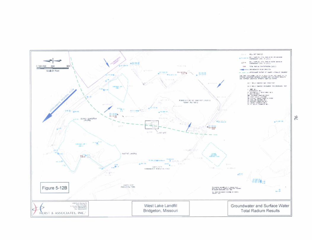


[•— EroslonA/egetatfve LayerTopsoll
1—~I—^~~~~-—_ -—L_r i— Infiltration Layer" I '-— —: j;—- ._-—I Low Permeability Soil
—- -—j (<1x10'5 cm/sec)
BIo-lntruslon/Marker LayerCaished Concrete orRock (6" Diameter Max)
|^- Waste & Fill
ENGINEERED LANDFILL COVER DETAILNOT TO SCALE FIGURE 12-2
oo


TABLES
80

Table 5-1 Summary of Constituents Detected in Groundwater - OU 1 RI
MaximumChemical Detected
Concentration(ug/1)
RadionuclidesRadium (total)Uranium (total)
Trace MetalsArsenicChromiumCopperLeadNickelSeleniumZinc
Volatile Organic CompoundsBenzeneTolueneEthyl BenzeneXylenesChlorobenzene1 ,2-Dichlorobenzene1 ,4-DichlorobenzeneCis-1 ,2-Dichloroethylene1 , 1 -DichloroethaneAcetone
Semi-volatile OrganicCompounds
1 ,4-Dichlorobenzene4-MethylphenolDi-n-octylphthalateBis(2-Ethylhexl)phthalate
89
420/40062/2276 /070/8
93/11038
330/77
111316511708
50348
68
382901317
DrinkingWater
Standards(ug/1)
530
50/10100
1,00015
NA50
5,000
51,000700
10,000NA6007570
NANA
75NANA400
No. of WellsChemicalDetected
Above MCL
20
4000000
3000000000
1000
NA - A drinking water standard (MCL) has not been established for these compounds.
81

Table 5-2: Summary of Radionuclide Occurrence Above Reference Levels inArea 1 Surface Samples
RadiologicalConstituents
Background Value(mean + 2 std dev.)
> Background but < Reference•f Detects Ranee
ReferenceLevel
> Reference Level$ Detects Ranee
Umuium - 238 Decav SeriesUraniuni-23SThoriiim-234Uranium-234Thoriimi-230Radium-226Lead-214Bisrmith-214Lead-210
2.24
2.762.73 •2.451.301.131.613.77
10111300
2.33-/-0.54
2.94-/-0.652.67- -0.761.32-/-0.24
1.16+/-0.44 to 1.62-h'-0.56
7.247.767.737.456.3
6.136.61S.77
2oii^•>^
3
S7-/-7.2 to 147+/-3S55.9^/-13.5 to 1SO-/-49105-/-22tol54+/-40
7.850-i-/-1.470 to 57.000 -'-4. 100109-,-5to9KH'-93
10S-;-Stol.lOi}+,'-99110^-6 to 1.000+/-57
:!06+.'-26tol.Q40+M35Ur.iniuin - 235 Decnv SeriesUraruum-235/236Proactiniuin-23 1Actiuiuffl-227Radium-223
1.15NENEME
1NENENE
5.7+/-1.9NENENE
6.15555
i-it1
6.S6^/-3.99tol9.5---5.9156-5-/-27 to 610-/-1 1011 8-:- 14 to 305+ '-33
113+/-NAto939-:-76Thorium - 232 Decav SeriesThoriuin-232Radiuui-228Thonmu-22SRadium-224Lead-212Bisinuth-212Thalliuni-208
1.552.371.33NE2.26NE0.71
001
NE0
NE1
1.96V-1.14NE
NE0.79^-0.83
6.557.376.33
57.26
55.71
i
001001
18.1+/-4.6to40^-/-150
1.760-/-219
6.8+/-11All vslue; expressed as pCi/g.NH = Not csrabfeheoi. all bBckgiound siniples below minimum detectable activir.'. NA = 2 Sisnu Error (T,A to:al of S surface soil samples r/er? colltcttd in Area 1. One of ±t sample; \vao split and ana!\ied at r.v
'., ie resulK fiorn ont of the laboratories were zreaet dian the backeround or reference levels.
0 is net avaihble.•o different laborJtories. For somt of tte\viule the retidts from tin; second iaboratory were tot.
82
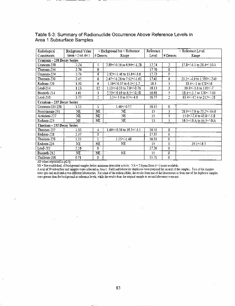
Table 5-3: Summary of Radionuclide Occurrence Above Reference Levels inArea 1 Subsurface Samples
RadiologicalConsnnients
Background Value(mean •*• 2 std. dev.)
> Background but < Reference% Detects Range
ReferenceLevel
> Reference Level=r Detects Range
Uranium - 238 Decav SeriesUraniiun-238Thonum-234Uramum-234Thonum-230Radium-226Lead-214Bisuiuth-214Lead-210
2.242.762.732.45
' 1.301.131.613.77
50666123i
2.89+/-0.56to6.94+/-1.28
2.92+/-1.46tol5.6+/-3.62.47^-1.26 to 7.52+/-1.65
1 36+/-0.37 to 6.3+/-1.21.13-r'-0.33to7.0+/-0.762.53-r.'-0.19to6.5-;'-0.5S
5.1+M.Otol7+/-4.0
17.2417.7617.7317.4516.3
16.1316.6118.77
2006333~i
17.S+/-4.1to26.4+M0.1
23.2+/-4.9tol,50{hv'-2401S.4-/-1 to 12S+/-6
19.9+.';-1.6tollO-'-7lS.4~/-1.2tol28^-7.00S3.4-/-12.4to212-h'-2S
Uranium - 235 Decav SeriesUraniurn-235/236Proactinuun-231Actiniiuu-227Radium-223
1.15NENENE
1NENENE
1.46^-0.57NENENE
16.15151515
0333
26.9+'-7.9to73.2+/-14.615.a-/-2.6to43.8-'-5.S16.1-/-NAto44.3-'-NA
Thorium - 232 Decav SeriesThorium-232Radium-228Thorium-22SRadiurn-224Lead-212Bismuth-212Thallniffl-208
1.552.371.33NE2.26NE0.71
401
NE0
NE0
1.64-H/-0.56tol0.3+/'-3.5
1.55^-1.48NE
NE
16.5517.3716.33
1517.26
1515.71
0001000
39.1-/-6.3
All value; expressed a;NE = Not established, all bscisroimd samples below minimum detectable activity. NA = 2 Sigma Error (-/-) is cot arjilsble.A tottl of 39 iubninace soil simple»v;m csilected in Area 1. Field and laboratory duplicates were prepared for several of i(were split and analyzed at two different hboratoriev. For some of the radioiiuclides. die results from one of die labontone; orwere neater than the backsround or reference levels, while the results frcm die orieiiial sample or second laboratory were not.
! iiampien. Two of tie .sample;from one of the duplicate saixpbs
83

Table 5-4: Summary of Radionuclide Occurrence Above Reference Levels inArea 2 Surface Samples
RadiologicalConstituents
Background Value(mean + 2 Hi dev.)
> Background but < Reference% Detects Ranee
ReferenceLevel
•-• Reference Level# Detects Ranee
Uranium 238 - Decav SeriesUranmm-238Thormm-234Uranium-234Thorium-230Radium-226Lead-214Bismwh-214Lead-210
2.242.762.732.451.301.131.613.77
30344520
3.1+/-0.7to4.17-rM.04
3.18+M.06to4.05-/-1.02'2.91+/-O.S2to5.35-;-1.141.54+M).22to4.78-.'-0.441.2S+/-0.2Sto5.26>/-0.493.56+.'-O.S7to4.2+/-0.67
7.247.767.737.456.36.136.618.77
T
0294443
134+M2to294-''-92
2Ki--67to575-h''-lSOS.63+/-2.62 to 29.24Qi-/-5.290
9.2+/-1.7to3.720t'-142S.8+/-1.0to3.19CH-/-2777.3-/-0.69to3.690-/-136
9.5S+/-2.32 to 1..370+A162Uranium - 235 Decav SeriesUnnium-235/236Proaciiniuin-231Actiniiun-227Radiuin-223
1.15NENENE
0NENENE
NENENE
6.15555
T
433
49Jr'-16.5to251-/-795.22+/-2.32 to 2.030+/-3016.15+/-1.17tolJ20+/-1796.73-/-NAtoL097-/-NA
Thorium - 232 Decav SeriesTliormm-232Radiuin-228Tliorium-228Radiiiffl-224Lead-212Bismuth-212Thalliuni-208
1.552.371.33NE2.26NE0.71
001
NE000
4.97-/-1.04NE
6.557.376.33
57.26
55.71
400"i
000
6.73-,'- 1.36 to 127-/-23
4.33CH-/-62S-o6.5S(h-/-1090
AU values exprfssed as pC'j-'g.NE = No; ei-abliiihedL all background iiarples bdow minimum detectable activir,-. NA = 2 Sigmi Error ^-) K col available.A totsl of 1 j surface soil samples v;ere collected in Area 2. Three of ike samples were spilt and anairced at two different laboratories. For some of theTadionuciides. the result; from one of the laboratories were pester than the background or reference levels, while the results from me second laboratory were no;.
84

Table 5-5: Summary of Radionuclide Occurrence Above Reference Levels inArea 2 Subsurface Samples
RadiologicalConstituents
Background Value(mean + 2 ;td. dtv )
Background but < ReferenceH Detects Range
ReferenceLevel
> Reference Level* Detects Range
Uranium - 238 Dec.iv SeriesUramuiu-238Thorium-234Uraniuffl-234Thorium-230Radiuni-226Lead-214Bismuth-214Lejd-210
2.242.762.732.451.301.131.613.77
716281723107
2.61+/-0.64 to 11.4-^-3.813.2+/-15.7
2.9W-0.4tol2.5+'-4.02.7K- 1.45 to 17.29+/-3.41.3-.'-0.45 to 12.9+/-0.541.14+/-0.24tol2.5-''-0.91.63+/-0.42tol2.6>/-0.64.02+/-1.6to9.S3+/-2.56
17.2417.7617.7317.4516.3
16.1316.6118.77
323184446
60.7+/-12.4to287--4724.5-KM5.S to 140-'-2545.4-/'-9.7to527+/-S7
lS.2~/-3.3TOS3.000-'-530SS.4-/-5.2to3.140+/-11685.9W-6.4to2.200+/-17093.2+/-5.1to3.150+.-lH22.4'->-'-3.5tol.300+M57
Uranium - 235 Decav SeriesUranium-235,'236Proactiiuum-231Actiiuum-227Radmm-223
1.15NENENE
0NENENE
NENENE
16.15151515
3444
24-r/-27toll5-/-1939.3-,'-ll.ltol.93(H'-24325.8rM.2toL180+/-13830.2-/-NAto5.270-/-3f.9
Thorium - 232 Decav SeriesThorium-232Radium-228Thorium-228Raduim-224Lead-212Bistnum-212ThaUium-20S
1.552.371.33NE2.26NE0.71
422
NE1
NE3
1.76+/-107to3.84-/-0.914.5-/-7.9tol6.7-i-/-9.3
1.5-/-0.80to4.59-i-/-0.91NE
2.49+/-0.94NE
1.13-''-0.7Sto7.9+/-3.7
16.5517.3716.33
1517.26
1515.71
3000100
1 06^-19 to 1SO+/-65
S2-i--'-35
AU values expressed as pCi-'NZ = Not escablished, nil background iaa^ile; below minimum detectable acn-.-i^-. NA = 2 Sipia Errcir (-;-) K nor availableA to:al of 73 subrjjface soil ^inqilfs v.-ere collected in ATM 2. Field lud labora;cry d«plica;es were prepared for several of the samples. Four of ie samples\vere spilt and tnalyzed 2; mo different laboiatories. For some of the radionuchdes. -ie results from one of ihe laboraiones or torn OIK of the duplicate s.uupleswere greater than ie background or reference levels, while ie re;ul;s from the oneinal sample or .second "laboratory '.vere not.
85

Table 5-6: Summary of Background Radionuclide Levels at the West Lake Landfill Site
RadionuclideDetectionFrequency Mean
StandardDeviation
Minimum
ValueMdxinnun
ValueMean Plus
2 Standard DemtionsMean Phis
3 Stundird Deviations VarianceUnmiurn-238 Decay SeriesUramurn-238Thcnuin-234l'raniii2i-234Thorrjni-230Radram-226Lead-214Bismuth-' i 4Lead-210
4/42/44/44;4
4/44/42;43/4
1.331.571.471.511.061.011.092.48
0.460.590.630.470.120.060.260.64
0.74^-0.35U5--O.S91.06-'-0.440.92-/-0.440.93-/-OJ20.92-/-0.26
- 0.9<K-0.31!.8S^,'-i.56
1.S5+/-0.79l.?9r'-l.li2.40r/-0.932.03^-0.61.19+/-0.221.07rM).2i1.27+-/-0.4
3.16+/:2.18
2.242.762.732.451.301.131.613.77
•> "t£. .'
3.333 ;62.9 i1.4i1.1?1.S74.41
0.210.350.400.220.01
0.0040.070.41
Urauium-235 Decay SeriesUramiun-235'236Ursmum-235Proacmaim-251Actiniuci-227Radium-223
4.4-----
0.39-----
0.38-
--
0.02-.:-0.08
----
0.91t-0.57------
1.15
-1
1.54-------
0.15-
--
Thorium-232 Decay SeriesThorium-232Radimn-22SThonuni-228Raduun-224Lead-212Bi;muth-212TliilliumOOS
4/4244,4-
4/4
4,4
0.901.650.65
--1.29-
0.44
0.330.360.33
--0.48
--0.14
0.52-/-0.29!.39-'-0.4
0.43--0.27--
0.80-.--0.31-
0.32-;-0.i6
1.26r,'-0.391.90+/-0.471.16+/-0.37
--1.94-,-0.29
-0.63-f/-0.21
1.552.371.33--
2.26--
0.71
1.872.731.66
--' 14
O.S-!
0.110.130.11-
0.23-
0.02
All value? expre.wed a; pCi-2. except detection frequency.Four background samples were analyzed. Samples without detections were not used to calculate background tDtishcs.
-- = Radionuclide; were not detected above die Minimum Detectable Activity (MDA) in any of the four background samples.
86

Table 7-1 Current Exposure Point Concentrations in Area 1 Soil
95% CL on the Arithmetic Mean
AnalyteUranium Series
Uranium-238-t-2dtrs
Uranium-234
Thorium-230
Radium-226 + 5 dtrs
Lead-210 + 2 dtrs
Actinium Series
Uranium-235 + 1 dtr
Protactinium-231 -H 8 dtrs
Thorium Series
Thorium-232 + 10 dtrs
Inorganic Chemicals
Arsenic
Organic Chemicals
Aroclor-1254
Surface Soil
118
122
8140
581
680
5.99 tt
365
25.8
139
0.70
All Depths
16.6
16.9
1060
71.6
88.6
0.84 a
47.3
4.14
NEb
0.48
Units
pCi/g
pCi/g
pCi/g
' PCi/g
pCi/g
pCi/g
pCi/g
pCi/g
mg/kg
mg/kg
Calculated using the uranium-238 and uranium-234 results and the expectedisotopic abundance in natural uranium.
indicates no exposure because the receptor is not exposed to subsurfacesoil.
87
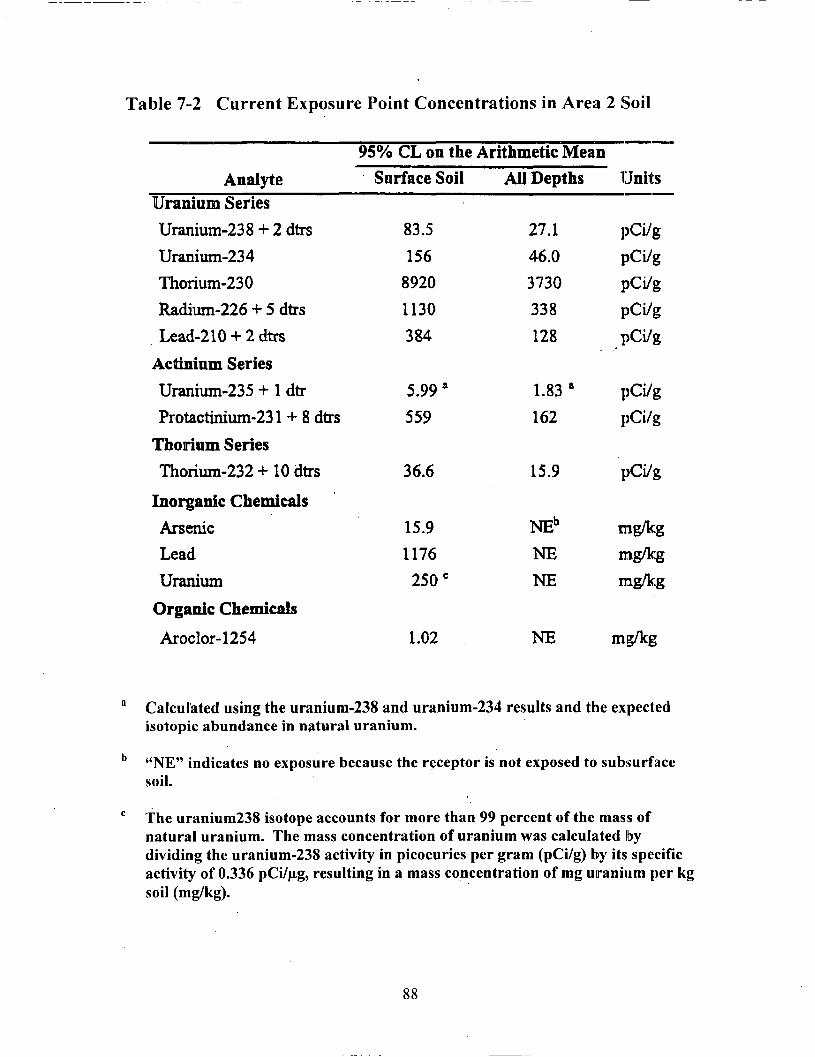
Table 7-2 Current Exposure Point Concentrations in Area 2 Soil
AnalyteUranium Series
Uranium-238 + 2 dtrsUranium-234
Thorium-230
Radium-226 + 5 dtrs
Lead-210 + 2 dtrs
Actinium Series
Uranium-235 + 1 dtr
Protactinium-231 + 8 dtrs
Thorium Series
Thorium-232 + 10 dtrs
Inorganic Chemicals
ArsenicLead
Uranium
Organic Chemicals
Aroclor-1254
95% CL on theSurface Soil
83.5
1568920
1130384
5.99 a
559
36.6
15.91176250 c
1.02
Arithmetic MeanAll Depths
27.146.03730
338128
1.83 a
162
15.9
NEb
NENE
NE
Units
pCi/g
pCi/gpCi/g
PCi/gpCi/g
pCi/gpCi/g
pCi/g
mg/kgmg/kg
mg/kg
m;g/kg
Calculated using the uranium-238 and uranium-234 results and the expectedisotopic abundance in natural uranium.
" indicates no exposure because the receptor is not exposed to subsurfacesoil.
The uranium238 isotope accounts for more than 99 percent of the mass ofnatural uranium. The mass concentration of uranium was calculated bydividing the uranium-238 activity in picocuries per gram (pCi/g) by its specificactivity of 0.336 pCi/jig, resulting in a mass concentration of mg uranium per kgsoil (mg/kg).
88

Table 7-3 Current Exposure Point Concentrations for theFord Property Soil
95% CL on the Arithmetic Mean
Analyte Surface Soil Units
Uranium Series
Uranium-238 + 2 dtrs 0.997 pCi/g
Uranium-234 1.01 pCi/g
Thorium-230 15 pCi/g
Radium-226 + 5 dtrs 1.08 pCi/g
Lead-210 + 2 dtrs 4.22 pCi/g'
Actinium Series
Uranium-235 +1 dtr 0.050a pCi/g
Thorium Series
Thorium-232 +10 dtrs 1.40 pCi/g
Calculated using the uranium-238 and uranium-234 results and the expectedisotopic abundance in natural uranium.
89

Table 7-4 Future Exposure Point Concentrations forArea 1 Soil
95% CL on the Arithmetic Mean
AnalyteUranium SeriesUranium-238 + 2 dtrsUranium-234Thorium-230Radium-226 + 8 dtrs
Actinium Series
Uranium-235 + 1 dtrProtactinium-231 + 8 dtrs
Thorium SeriesThorium-232 + 10 dtrs
Inorganic ChemicalsArsenic
Organic ChemicalsAroclor-1254
Surface Soil
118122
81403224
5.99 a
365
25.8
139
0.70
All Depths
16.616.91060417
0.84 a
47.3
4.14
NEb
0.48
Units
pCi/gpCi/gPCi/gPCi/g
.-• S
PCi/gpCi/g
pCi/g
mg/kg
rag/kg
Calculated using the uranium-238 and uranium-234 results and the expectedisotopic abundance in natural uranium.
«NE" indicates no exposure because the receptor is not exposed to subsurfacesoil.
90

Table 7-5 Future Exposure Point Concentrations forArea 2 Soil
95% CL on the Arithmetic Mean
AnalyteUranium SeriesUranium-238 + 2 dtrsUranium-234Thorium-230Radium-226 + 8 dtrs
Actiniam Series
Uranium-235 + 1 dtrProtactinium-231 + 8 dtrs
Thorium SeriesThorium-232 + 10 dtrs
Inorganic ChemicalsArsenicLeadUranium
Organic ChemicalsAroclor-1254
Surface Soil
83.5156
89203853
5.99*559
36.6
15.91176250 c
1.02
All Depths
27.146.037301524
1.83 tt
162
15.9
NEb
NENE
NE
Units
pCi/gpCi/g
PCi/gpCi/g
pCi/gpCi/g
pCi/g
mg/lcgmg/lcgmg/lcg
mg/kg
a Calculated using the uranium-238 and uranium-234 results and the expectedisotopic abundance in natural uranium..
b "NE" indicates no exposure because the receptor is not exposed to subsurfacesoil.
c The uranium-238 isotope accounts for more than 99 percent of the mass ofnatural uranium. The mass concentration of uranium was calculated bydividing the uranium-238 activity in picocuries per gram (pCi/g) by its specificactivity of 0.336 pCi/ug, resulting in a mass concentration of mg uranium per kgsoil (mg/kg).
91

Table 7-6 Future Exposure Point Concentrations forFord Property Soil
95% CL on the Arithmetic Mean
AnalyteUranium SeriesUranium-238 + 2 dtrsUranium-234Thorium-230Radium-226 + 8 dtrs
Surface Soil
0.9971.0115
5.95
Units
pCi/gpCi/gpCi/gpCi/g
Actinium Series
Uranium-235 + 1 dtr 0.050 a pCi/g
Thorium SeriesThorium-232-MOdtrs 1.40 pCi/g
Calculated using the uranium-238 and uranium-234 results and the expectedisotopic abundance in natural uranium.
92

Table 7-7 Future Exposure Point Concentrations in Air
Analyte
95% Confidence Limit on the Arithmetic Mean of Surface
Soil x Mass Loading Factor of 50 )ig/m3
Area 1 Area 2 Ford Property UnitsUranium Series
Uranium-238 + 2 dtrs
Uraniura-234
Thorium-230
Radium-226 •+• 8 dtrs
Radon-222
Actinium Series
Uranium-235 + 1 dtr
Thorium Series
Thorium-232 + 10 dtrs
Inorganic Chemicals
Arsenic
Lead
Uranium
Organic Chemicals
Aroclor-1254
5.89 E-3
6.10E-3
4.07 E-l
1.61 E-l
1.89E+1'
3.00 E-4 b
1.29 E-3
4.18 E-3
7.80 E-3
4.46 E-l
1.93 E-l
6.67 E+l a
2.99 E-4 b
1.83 E-3
4.99 E-5
5.03 E-5
7.50 E-4
2.97 E-4
3.98 E-2 a
pCi/m3
pCi/m3
pCi/m3
pCi/m3
pCi/m3
2.50 E-6 b pCi/m3
7.00 E-5 pCi/m3
6.97 E-3
NA
NA
7.93 E-4
5.88 E-2
1.25 E-2
NAe
NA
NA
pig/m3
ptg/m3
pig/m3
3.48E-05 5.10E-05 NA
a Calculated from the predicted radium-226 concentrations in soil.
b Calculated using the uranium-238 and uranium-234 results and the expectedisotopic abundance in natural uranium.
c U ND" indicates the radionuclide was not detected.
" indicates not applicable. Preliminary screening removed the chemicalfrom consideration in this area.
93

Table 7-8 Radiological Carcinogenic Slope Factors
Inhalation CancerSlope Factor
Constituent (pCi'1)Uranium SeriesUranium-238 + 2 dtrsUranium-234Thorium-230Radium-226 + 8 dtrsRadium-226 + 5 dtrsRadium-226Radon-222 + 4 dtrs
Radon-222 in Outdoor Air b
Lead-210 + 2dtrs
Actinium SeriesUranium-235 + 1 dtrProtactinium-231+ 8 dtrs
Thorium SeriesThorium-232 + 10 dtrs
1.24 E-81.40 E-81.72 E-86.61 E-92.75 E-92.72 E-97.57 E-12
7.3 E-133. 86 E-9
1.30 E-81.03 E-7
1.17 E-7
Oral Cancer Slope External CancerFactor Slope; Factor
SF0 SF.(pCi-1) (g/pCi-y)
6.20 E-ll4.44 E-ll3.75 E-ll1.31 E-9
2.96 E-102.95 E-10
NANA
1.01 E-9
4.70 E-ll7.75 E-10
5.11 E-10
5.25 E-82.14 E-ll
-' 4.40 E-ll6.74 E-66.74 E-61.31 E-8
NA
NA1.45 E-10
2.65 E-76.24 E-7
4.27 E-6
* EPA assumes all radionuclides are Class A carcinogens. Slope factors used are from EPA 199? "HealthEffects Assessment Summary Tables Update," unless noted.
b Radon daughters have not had enough time to appear before the released radon-222 reaches the exposurepoints selected in this risk assessment. To reflect this, the radon-222 slope factor (without daughtercontributions) from EPA's March 1994 "Health Effects Assessment Summary Tables Update" was usedfor outdoor Rn-222 exposures
94

Table 7-9 Chemical Carcinogenic Slope Factors a
Constituent
Aroclor-1254
Arsenic
Lead
Uranium
Inhalation CancerSlope Factor
SF,[l/(mg/kg-d)]
2.00 E+Ob
1.54E-H
ND
ND
Oral Cancer SlopeFactor
SF0
[l/(mg/kg-d)]
2.00 E+Ob
1.50E-K)
ND
ND
InhalationTumor Site
NDe
Respiratory tract
ND
ND
Oral Tumor Site
LiverSkin, liver, lung,
bladder
Kidney
ND
CancerClassification
B2b
A
B2
ND
Dermal CancerSlope Factor
SF,[l/(mg/kg-d)]
2.22 E+0
I.58E-K)
ND
ND
° References: Integrated Risk Information System (EPA 2000), Health Effects Assessment Summary Tables (EPA 1997c).b Slope Factors for polychlorinated biphenyls are given. Cancer slope factors for Aroclor-1254 are not available.c ND signifies that no data were available.
95
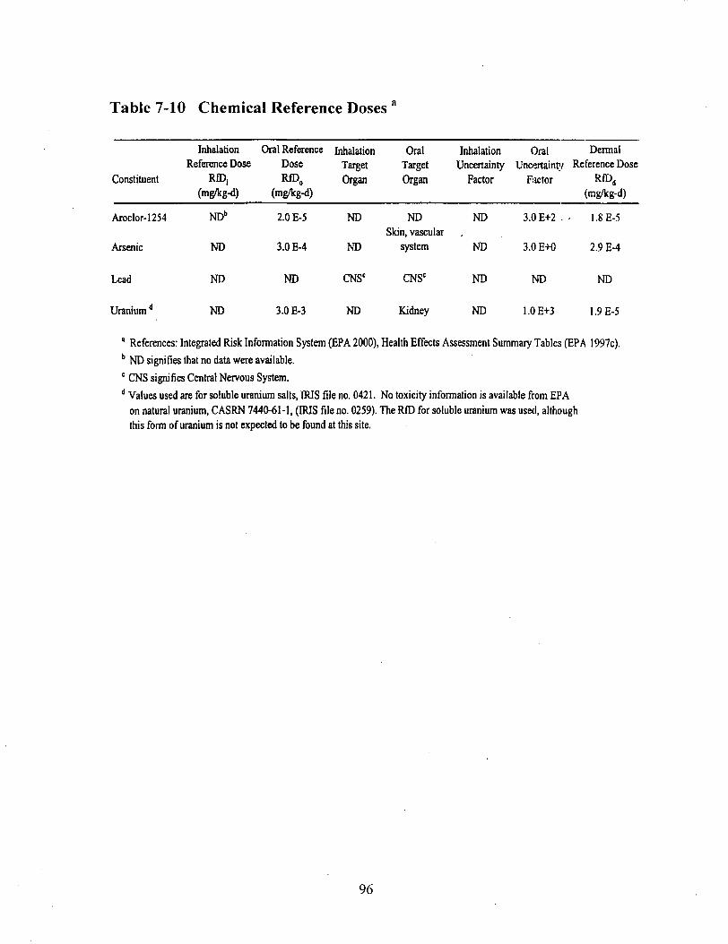
Table 7-10 Chemical Reference Doses a
Constituent
Aroclor-1254
Arsenic
Lead
Uranium d
InhalationReference Dose
RfDj(mg/kg-d)
NDb
ND
ND
ND
Oral ReferenceDoseRfD0
(mg/kg-d)
2.0 E-5
3.0 E-4
ND
3.0 E-3
InhalationTargetOrgan
ND
ND
CNSe
ND
OralTargetOrgan
NDSkin, vascular
system
CNSC
Kidney
InhalationUncertainty
Factor
ND
ND
ND
ND
OralUncertainty
Factor
3.0 E+2 .
3.0 E+0
ND
1.0 E+3
DermalReference Dose
R«>,(mg/kg-d)
1.8 E-5
2.9 E-4
ND
1.9 E-5
' References: Integrated Risk Information System (EPA 2000), Health Effects Assessment Summary Tables (EPA 1997c).6 ND signifies that no data were available.c CNS signifies Central Nervous System.d Values used are for soluble uranium salts, IRIS file no. 0421. No toxiciry information is available from EPA
on natural uranium, CASRN 7440-61-1, (IRIS file no. 0259). The RID for soluble uranium was used, althoughthis form of uranium is not expected to be found at this site.
96

Table 7-11 Calculated Incremental Lifetime Cancer Risksfor the Landfill Groundskeeper Scenario
Area 1 - Future Conditions
Exposure Route
Constituent
Uranium Series
Uranium-238 + 2 dtrsUranium-234
Thorium-230Radium-226 + 8 dtrs
Actinum SeriesUranium-235 + 1 dtrProtactinium-23H- 8 dtrs
Thorium SeriesThorium-232 + 10 dtrs
Inorganic ChemicalsArsenic
Organic ChemicalsAroclor-1254
Total RiskRadiocarcinogenicChemocarcinogenic
SoilIngestion
1E-81E-86E-78E-6
6E-106E-7
3E-8
2E-7
2E-9
1E-52E-7
Inhalation
2E-82E-81E-6
2E-7b
8E-104E-7
3E-8
1E-8
8E-12
2E-61E-8
DermalAbsorption
NEa
NENENE
NENE
NE
5E-9
6E-11
NE5E-9
Direct- Radiation
2E-87 E-128 E-105E-5
4E-95E-7
3E-7
NE
NE
5E-5NE
All Routes
5 E-83E-82E-66E-5
5E-91E-6
4E-7
2E-7
2E-9
6E-52E-7
' "NE" - No exposure anticipated because a complete exposure pathway does not exist.b Includes risks from inhalation of particulates and radon-222 gas
97

Table 7-12 Calculated Incremental Lifetime Cancer Risksfor the Landfill Groundskeeper Scenario
Area 2 - Future Conditions
Exposure Route
Constituent
Uranium SeriesUranium-238 + 2 dtrsUranium-234Thorium-230Radium-226 + 8 dtrs
Actinum SeriesUranium-235 + 1 dtrPiDtactinium-23 1+ 8 dtrs
Thorium SeriesThorium-232 + 10 dtrs
Inorganic ChemicalsArsenicLeadUranium
Soil Ingcstion
1E-81E-87E-71E-5
6E-109E-7
4E-8
2E-8NSC
NS
Inhalation
1E-82E-82E-63E-7b
8E-106E-7
4E-8
1E-9NSNS
DermalAbsorption
NE1
NENENE
NENE
NE
5E-10NSNS
DirectRadiation
3E-82E-113E-92E-4
9E-92E-6
1E-6
NENENE
AH Routes
5E-84E-82E-62E-4
1E-83E-6
1E-6
3E-8--
Organic ChemicalsAroclor-1254 2.0 E-9 l.OE-11 9.0E-11
Total RiskRadiocarcinogenic 1E-5 3 E-6 NEChemocarcinogenic 2E-8 1 E-9 6E-10
* "NE" - No exposure anticipated because a complete exposure pathway does not exist.b Includes risks from inhalation of particulates and radon-222 gas0 "NS" - Intake calculation is not applicable because EPA has not published a slope
factor for use in quantifying the risk from this contaminant via this exposure route.
NE
2E-4NE
2.0 E-9
2E-43E-8
98

Table 7-13 Calculated Incremental Lifetime Cancer Risksfor the Landfill Adjacent Building User Scenario
Area 1 - Future Conditions
Exposure Route
Constituent
Uranium Series
Uranium-238 + 2 dtrs
Uranium-234
Thorium-230
Radium-226 + 8 dtrs
Actinum Series
Uranium-235 + 1 dtr
Protactinium-231+ 8 dtrs
Soil Ingestion inhalation
NE'
NENENE
NENE
NENENENE
NENE
NENENENE
NE .
NE
DermalAbsorption
NENENENE
NENE
DirectRadiation
3E-9
1E-12
- 2E-IO
1E-5
8 E- 10
1E-7
All Routes
3E-91E-122E-10
1 E-5
8E-101 E-7
NE NE NE NEThorium Series
Thoriura-232 +10 dtrs
Inorganic Chemicals
Arsenic
Organic Chemicals
Aroclor-1254
Total Risk
Radiocarcino genieChemocarcinogenic
* "NE" - No exposure anticipated because a complete exposure pathway does not exist
7E-8 7E-8
NE
NE
NENE
NE
NE
NENE
NE
NE
NENE
NE
NE
NENE
NE
NE
1E-5NE
OE+0
OE+0
1E-5OE+0
99

Table 7-14 Calculated Incremental Lifetime Cancer Risksfor the Landfill Adjacent Building User Scenario
Area 2 - Future Conditions
Exposure Route
Constituent
Uranium Series
Uranium-238 + 2 dtrs
Uranium-234
TTiorium-230
Radium-226 + 8 dtrs
Actinnm Series
Uranium-235 + l.dtr
Protactinium-23 1 + 8 dtrs
Thorium Series
Thorium-232+10dtrs
Inorganic Chemicals
Arsenic
Uranium
Organic Chemicals
Aroclor-1254
Total Risk
Radi ocarcinogenic
Chemocarcinogenic
Soil Ingestion inhalation
NE"NENENE
NENE
NE
NENE
NE
NENE
NENENENE
NENE
NE
NENE
NE
NENE
NENENENE
NENE
NE
NENE
NE
NENE
DermalAbsorption
NENENENE
NENE
NE
NENE
NE
NENE
DirectRadiation
5E-9
4E-12
- 6E-10
4E-5
2E-9
4E-7
3E-7
NENE
NE
4E-5
NE
All Routes
5E-94E-12
6E-10
4E-5
2E-9
4E-7
3E-7
OE-H)
OE+0
OE+0
4E-S
OE+0
11 "NE" - No exposure anticipated because a complete exposure pathway does not exist.
100

Table 7-15 Calculated Incremental Lifetime Cancer Risksfor the Landfill Storage Yard Worker Scenario
Area 1 - Future Conditions
Exposure Route
Constituent
Uranium Series
Uranium-238 + 2 dtrs
Uranium-234
Thorium-230
Radium-226 + 8 dtrs
Actinum Series
Uranium-235 + 1 dtr
Protactinium-231+ 8 dtrs
Soil Ingestion inhalation
NE'
NENENE
NENE
NENENENE
NENE
NENENENE
NENE
DermalAbsorption
NENENENE
• NE
NE
DirectRadiation
3 £-8
1E-11
- 2 E-9
1E-4
8 E-9
1E-6
All Routes
3E-8
1E-11
2 E-9
1E-4
8 E-9
1E-6
Thorinm Series
Thorium-232 + 10dtrs NE NE NE NE 7E-7 7 E-7
Inorganic ChemicalsArsenic NE NE NE NE NE OE+0
Organic Chemicals
Aroclor-1254 NE NE NE NE NE OE+0
Total RiskRadiocarcinogenic NE NE NE NE 1E-4 1E-4
Chemocarcinogcnic NE NE NE NE NE OE+0
* "NE" - No exposure anticipated because a complete exposure pathway does not exist.
101

Table 7-16 Calculated Incremental Lifetime Cancer Risksfor the Landfill Storage Yard Worker Scenario
Area 2 - Future Conditions
Exposure Route
Constituent
Uranium Series
Uranium-238 + 2 dtrs
Uraniura-234
Thorium-230
Radium-226 + 8 dtrs
Actinum Series
Uranium-235 + 1 dtr
Protactinium-23H- 8 dtrs
Thorium Series
Thorium-232 + 10 dtrs
Inorganic Chemicals
Arsenic
Uranium
Total Risk
Radiocarcinogenic
Chemocarcinogenic
Dermal DirectSoil Ingestion Inhalation Absorption Radiation.
NE1
NE
NENE
NE
NE
NE
NE
NE
NENE
NE
NE
NENE
NE
NE
NE
NENE
NENE
NE
NE
NENE
NE
NE
NE
NENE
NE
NE
NE
NE
NENE
NE
NE
NE
NE
NE
NE
NE
5E-8
4E-11
6E-94E-4
2E-8
4E-6
3E-6
NENE
4E-4
NE
All Routes
5E-8
4E-116E-94E-4
2E-8
4E-6
3E-6
OE+0
OE+0
4E-4
OE-H)
"NE" - No exposure anticipated because a complete exposure pathway does not exist
102
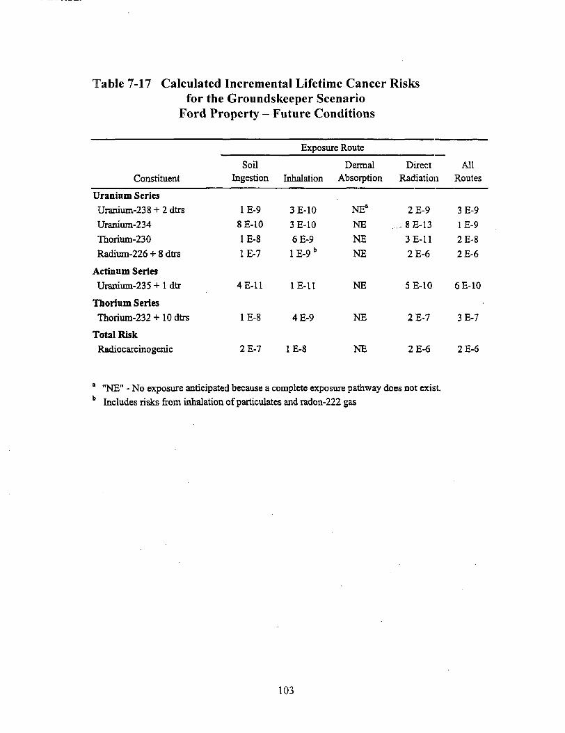
Table 7-17 Calculated Incremental Lifetime Cancer Risksfor the Groundskeeper Scenario
Ford Property - Future Conditions
Constituent
Actinum Series
Uranium-235 + 1 dtr
Thorium Series
Thorium-232 +10 dtrs
Total RiskRadiocarcinogenic
Exposure Route
Soil Dermal Direct AllIngestion Inhalation Absorption Radiation Routes
Uranium Series
Uranium-238 + 2 dtrs
Uranium-234Thorium-230
Radium-226 + 8 dtrs
1E-9
8E-10
1E-8
1E-7
3E-10
3E-10
6E-9
lE-9b
NE°NE
NENE
2E-9
, . ,8E-133E-11
2E-6
3E-9
1E-9
2E-8
2E-6
4E-11
1E-8
2E-7
1E-U
4E-9
1E-8
NE
NE
NE
5E-10 6E-10
2E-7
2E-6
3E-7
2E-6
a "NE" - No exposure anticipated because a complete exposure pathway does not exist.b Includes risks from inhalation of particulates and radon-222 gas
103
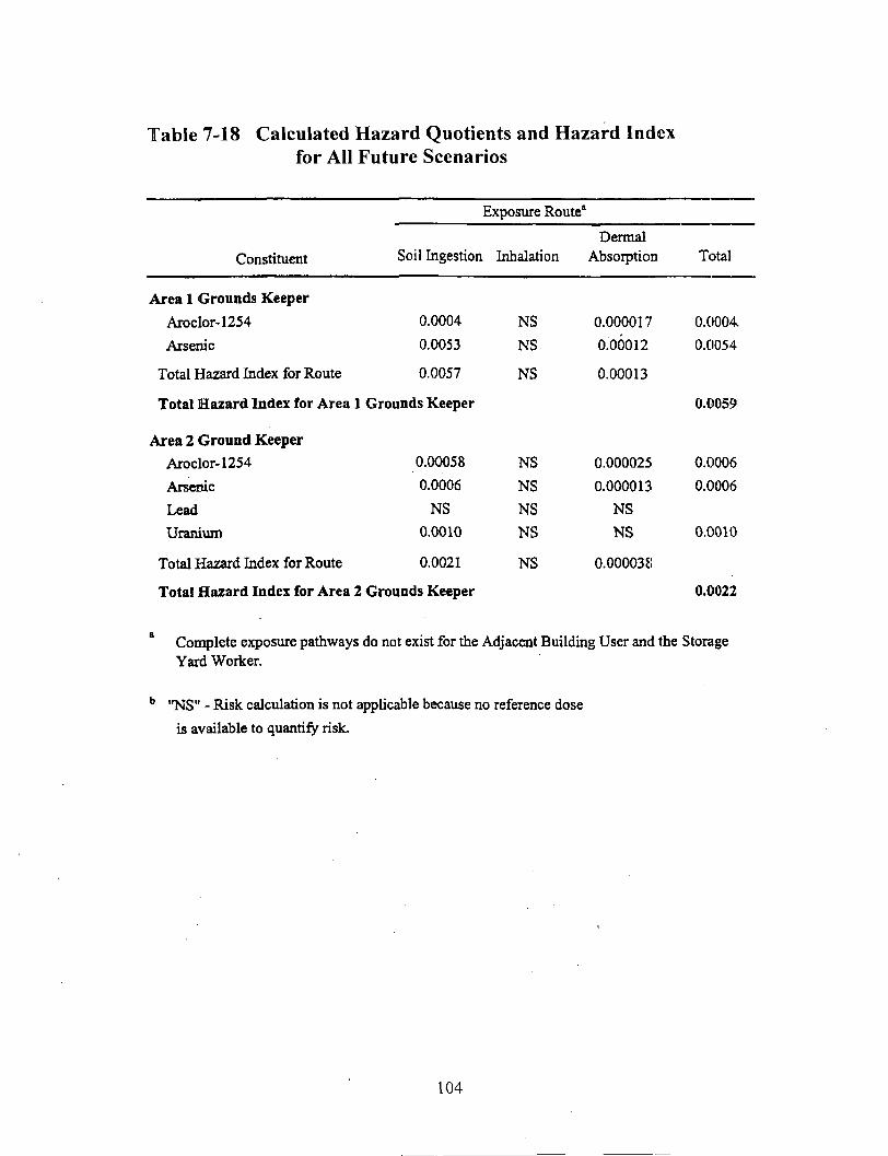
Table 7-18 Calculated Hazard Quotients and Hazard Indexfor All Future Scenarios
Exposure Route*
ConstituentDermal
Soil Ingestion Inhalation Absorption Total
Area 1 Grounds Keeper
Aroclor-1254
Arsenic
Total Hazard Index for Route
0.0004
0.0053
0.0057
NS
NS
NS
0.000017
0.00012
0.00013
0.0004
0.0054
Total Hazard Index for Area 1 Grounds Keeper
Area 2 Ground Keeper
Aroclor-1254
Arsenic
Lead
Uranium
Total Hazard Index for Route 0.0021
Total Hazard Index for Area 2 Grounds Keeper
NS 0.000038
0.0059
0.00058
0.0006
NS0.0010
NS
NS
NSNS
0.000025
0.000013
NS
NS
0.0006
0.0006
0.0010
0.0022
Complete exposure pathways do not exist for the Adjacent Building User and the StorageYard Worker.
b "NS" - Risk calculation is not applicable because no reference dose
is available to quantify risk.
104

Table 7-19 Summary of Risks for Future Receptor Scenarios
Risks
Total Cancer Risks
Radionuclides
Chemicals
Hazard Index
ItO
6E-5
6E-5
2E-7
0.0059
6fr
M ,£
It1
2E-4
2E-4
3E-8
0.0022
b5a1
rH -3
Si5 «% «j8^*
1E-5
1E-5
NE'
NE
On-site
Sin
N "O
815 050
I1
<
4E-5
4E-5
NE
NE
.xo
\l
IC/3
1E-4
1E-4
NE
NE
S
N |
o60
aW
4E-4
4E-4
NE
NE
Off-site
is«.! o
? §0 g
2E-6
2E-6
NE
NE
1 "NE" - No exposure anticipated because a complete exposure pathway does not exist.
105

Table 7-20
Summary of Exposure Pathways for Ecological Receptors
Ta» Direct Contact Ingestloa Ingestion Injestion Ingeition Prey Ingestkm Prey IngcslionSoib Vegetation InYerlehfalB Mammals Hints
Plants X
Soil Invertebrates XWhile-fooled MouseColionlai! RabbitRed FoxAmerican RobinAmerican WoodcockKed-uiledilawk
XXXXX
XXXX
X
X XXX
X
XX
X XXX
X X
106

Table 7-21
SUMMARY OF RISK FINDINGS FOR THE PLANTS AND INVERTEBRATES, AREA :
ChemicalInorganic!ArsenicBerylliumCadmium
ChromiumCopperL«adMercury
NickelSeleniumUraniumZinc
Organic!Acetone8ii(2-e[hylhcjcyl)phihalateDi-n-octylphlhaUte1 ,4-DichlOrobertzeneFluonnlheneXylenes
Pciileldes/PCBiAldrinAraelorl2S44.4-.DDD4.4--DDT
95% ClConcentration
fmg/kg)
J.JOE+Ol2.20E+000.30E+004.90EMJI
3.60E-HJ22.20E+032.70E-016.SOE+02J-SOE-H)!
8.73E-HJ24.00E+02
3.SOE-027.70E+OI1.20E+016.50E-038.50E-K10I.20E-02
1. 70 E -03I.60E-HW7.60E^)39.30E-03
Plant]atnehmjrk
Conetniralion(mi/Vs)
t.OOE*OlI.OOE+OI3.00E*001 .OOE-KJO1.00E-H)23.00E-01
3.00E-OI3.00E-HJIl.OOE+00
5.00E+005.00E+OI
NDND
2.00E+02NDNDND
ND4.00E-KH
NDND
HazardQuollint
< H Q >
J.JOE-^O2.20E-012.10E*00
4.90E-KMJ-OOE^-OO4.40E-K)!
9.00E-OI2.27E-HJI3.SOE+OII.7SE*02S.OOE-t-OO
NDND
6.00E-02NDNDND
ND4.00E-02
NDND
95% ClConctnlrallon
(me/kE)
3.50E*OI2.20E^OO6.30E^OO4.00E-KJ13.60E+022.20E-K)3
2.70E-OIft.80E-K)2
3.80E-KM8.7SE-^02
4.00E*02
3.80EX)27.70E+OII.20E+016.50E-03S.50E+001 .20E-02
I.70E-03!.tOE-007.00E-03
9.30E-03
Invrr t rbra ic jBenchmark
Concentrat ion
<ir ia / l<B>
(i.OOE*OIND
2.00E-01400E-OIi.OOE+015.00E+Q2
I.OOE-012.00E+027,OOE*OI
ND2.00E*C2
ND2.00E+022.00E^C22.0QSTOI3.00E-KM
ND
2.20 E+00ND
2.00E+<i32.00E1-03
HazardQuotient
< H Q >
5.83E-OIND
3.liE-01I.23E-K):7.20E-*-004.4QE+002.70E^OO3.40E+005.43E-01
ND2.00E-KJO
ND3.S5E-016.00E-023.25E-04
2.S3E-01NC3
7.73E-04
ND3.80E-064.65E-06
Tot all: 3.47E4-02 1.44E+02
107

Table 7-22SUMMARY OF RISK FINDINGS FOR WII.DLJKE WITH SMALL HOME RANGES, AREA I
Wkllr-fcMfnl M»«»t
Cbrnltil
InuitinlM
Arwok
UciylHum
(,'admiura
Ctiiuiniumrtvpjiti
Lead
McirunrNKkcl
ScU'lUUJl)
Ihaniuut
X.lnc
Orftalci
Acflnnc
Itbll-ciliyNwsyDpliflnlluhj-n-kktylphlluljiv
1 .4-l)'»chliiiitlirii/i-ui;
I1 liulrtnthcuc
Xylenti
rtilkhlivri III
AUrin
Ank'U 12S4
4.4'-nnn4.4--nur
Unlit
tatflttHttt
I.IIEtOI
1 OJE-OJ
».J1E*OI
).72EtOI
6.IOL»02
I.56E<0)
I.19E<003.01 t*OI
I.S7Et02
1 09b»(»
1 U-)E>OU
o.ne-02»«ir.t(Ki2 i»i;«oo(,,Wl:*l
<J.7fll:-OI
IJIE-DJ
I.1IE-04
2.03E-OIQ.6SC-04
I.23E-01
Bcirhmtrk
ViUclai/k ir)
IJ6E-OI
I.UEtOO
1.9)0*00
5.47KfO)3.04L-UI
l.bOEtOI
2.60LHXI
7.»F.tttl
3.99E-OI
3j*n+co3.201: 102
2.ftOHtOI
I.VIIiHIl
Nl)
4.711:<OI
i.mtioo2J7t»»0
J.WE-OI
O.IOE-02
I.60E1DO
I.60E*OU
IliiirilQiillcDl
(HO)
I.I«E-OI
7.70E-03
4.a)E»UI
6.1 IE -032lllu*UI
4.74F>UI
4.97E-OI
l,77n-OI
l.WtfOJ334E-OI
) 41 11-03
3.22T.-OJ
4.3UL-OI
Nil1 4Ki:-()5
84811 01J7HC.UJ
4.7«ri-IMJ.JJEKK)
6 03r-D4
7.7IE-04
CtlMollll Rlbbll
link!
(«, l d.rl
i.soe+oo3.UEOJ
4.47EtOI .
«.ISE-OI
64jn*02
2.93EV02
5.I4E-02I.Wli'UI
I.9IE»UJ
i.24n<ml.24E<tll
80JC-02
I.IOE<OU
I50P.6I
I90E-U-I1 24I:-OI
4 IOI--04
O/HH-Oi
J.08E-02
9.')OEOS
I.IOE-04
OfDckmilk
Vilui
(nit/kCOv)
5,OOE-«2
4.ME-OI
7.ME.OI
JOIEiOl
MJI-'OI
5 »E«ttO
v.tflE-OI
294E»OI
1.476-011 30E»Ofl
I.l«b-Ui
7.30EtOO
7.JIILKIO
NI>I.2SE-IUI4UOE-OI
8 JSC-OI
I.47E-OIi.JUtOJ
5.901; -015,901': -01
IlilirdQuolkHl
IIIOI
I.76I:»02
t.)OE426.3lttQI
J4IE-04
3.71I:«OI
J.OMltOI
5.35E02363E-OI
IJSEi03
I.03E10I
l.oK-Cit
I.IOE-02
1.5(1 1- -01Nl)
IJJE-OJ3.IOE-OI
4. Till: -04
4.711! -04mt-oi\.M:-M
2.02I--I14
IXlikl(ntirkiifdor)
4,l»EtOI
} I9C -02
3JOE*01
I.07FI02J 5fll;in)
4.76E»03
3,76b<OQ9.]4F:*fll
b84E»02J Hi:t(rt
4 141:1110
i.Tlf.-Kl
: ivi'iiii6.27K<UO
2 1511 -11.12«2l-:iOO
4.0'Jl.L-O]
b.UKI'.-IM
S.17IT-OI
l.7"H:4»
3.i6l:4i3
Awcricil KebliUrochnvrk
Vikit(ml/k^Jil)
*.IP1>00
Nil1'l.«iE+00
1 MK-fW
4.70E'GI
3.85U'OU
4.50E 01
7.74Cifll
J UOl .02
1 .Mll'-'DI
l.4)l:->lll
NP
l.ltil^UO
Nl)
Nl)
NilNl)
Nt)
1 IOF 01
3 Ollli-Ulj on-:. in
illaurilQamkitl
(HO)
I7ll:ifl0
Nl)2.701:11)2i rur.Mij5.321:11)1
I.24I:»0>1 )!l-t<>0
1 .JWLMIO
1.37i:>04
Mil: -01
2Hl.i:-UI
Nil
MM; miNl)
Nl)
NO
Nil
Nl)
3 2lil:fW)
9.11I-.-OI1 I1I-IUCI
T«.h;
' NO" ln»riic>em Jail lactic u
6.47EK>2 I.70OO.I
108

Table 7-23SUMMARY OF UISK FINDINGS FOR WILDLIFE WITH LARGE HOME RANGES, OPERABLE UNIT I
Rcd-lilletl foi American Woodtock R«Millfd
Cbetnlnlluortauta
Antimony
Arunic
Dcryllium
Cadmium
Chromium
Copper
Cyanide
LeadMercury
Niclel
Selenium
Thallium
UraniumZinc
Or£»nlci
Acetone
Bis(2-oiliylhejiyl)phihaljic
Uulyl benzyl phlhaljlc
ChlorobcnzencOi-n-biilylphthjUtc
2,4-Dimclhylphcnol
Di-n-ociylphthulale
1.2-DiclilDrobcnztne
1,4-Dichlaraben/ene
Ethyl be nientFlooramhent
Fluarcne
Intake
I.J4E-02
8.08E-OI
1.54 E-02
J.57C4III
i.iOEtno2.26C101
3.08E-03
2.88E<OI
J.73L:-03
I.24£»OI4.98E+00
3.30E-03
') 52E-OI
9.ME+OI
3SGE-02
303E-HI5.04E-OI7,IK)E4)J
2.80E-02
5.46E-05
J.15E-OI
2.80E-M
7.02E-035.60E-02
2.86E-02
I.UIE-0)
Bin<bmirkVilut
3.60E-02
3.60E-02
3.50E-OI
5.1WE-OI
I.4SE+01
8.00E»00
J.4IU+OI
4.22EiOII6WU4.II
2 ME*-OI
I 06E-OI
4.00E-0)
8.62Et()0
«.4jnt..|
s joEion5.2UE+OH
6.79£tOI2.C9EK)0
I.S7EKI29.^IE-OI
ND3 66F,»OI
3.02E+00
4.HE+01
2.WE41I
2.90G-OI
llazanlQgotleol
(IIQ)
3.73E-OI
2.24E+OI
4.4 1 E-02
7.0IE>OI
7.40E-04
2.83E<00
9.03E-05
6.83EIOO1 .26E-02586E-OI
4.70ErOI
B.4IE-OI
I.IIIE-OI
l.luEtltt
6.72E-03
5.82E-IIJ
7.43E-UJ
2.IIIC-03I.78E-04
5.80E-03
ND7.65E-08
B.75E.04
I.35E-0!985E-OJ3.48E-U)
Inlakt
NA'3.72EtOO
3-59HfflO
3.94UH1I
2.6IE*OI
8.36EtOI
NA1, 0861-0)
t.3ll!-OI
7.I9E*OIJ.62EtOO
2.04E-03I.S8CH12
I.88EI02
2.3tE-03
d.52E+0(l
NA
NANA
I.64E^)4
I.SVEt 'OO
NA9.64E-04
4.8UE-066.96l-:-OI
NA
Value(me/kj/day)
ND:
S.IOEtOO
NDl.45E+tW)
I.OOE.OO
4.70E«ni
NO3.85fi+«l
4.50E-OI
7.74EtOI
5.00E-02
NOI.60E4DI
1.451: Mil
NDI.IOEiliO
NONU
LionelNO
NO
NO
NO
ND
NO
NO
HazardQuolieol
(110)
NA7.29E-OI
NO2.72E^OI
2.6IU+01
I.7BE^OO
NA2.50HI02
1 US THOU
9.29E-OI
765E10I
NDI.ISEiOl
I.JOHtOI
ND5.92E«Oft
NANA
NA
ND
NO
NAND
NO
ND
NA
Intake
2.7.1K-1I4.62F..04
1 7711-10
3 I2K-OI
),75E-t)J
2.14E-00
NA
I.S7E-OI
I.'J8IM144.46E-OJ
5.95E-ni
2.')4K-»I7
I.I3IMI71 l)l:.-»)7
1 .01 E.flB
4..15E-I14
j.jsn-osl.:i8E-03l.'MEiir,I.58E-OS
i:.!9E-02
1 44 E- II4.34E-08
fi 1(SIM)7
3.'l7E-»5
I.ri?l:-n8
BenchmarkValue
(rue/kgJdjy)
NDS.IOEtOO
ND1. 45 E Kill
1 (lOKKKl4.70Etn|
ND
J.KSEt'K)4.:i()E-(H
7.7-tE*OI
5. 00 E-02
Nl)I.MIEHII
I .45E-OI
NO
i.mntiioNO
NO
1. Mil: -01
NP
NO
ND
Nl)
ND
NO
Nil
lla»rdQutHicul
(HOI
ND
il.fif.H-0<
ND
2.I5E-OI
J.7SE-01
4.5f,E-02
NA
4.0BE-02J.J!)I-;.04
5.71E-041.1'IEtOI
ND
7.I«E-(W
2.SJU-IW
ND
4II5E-D4
ND
NO
1 7.in-ojND
ND
Nl)
NO
HI)
Nl>
Nl)
109

Table 7-23 (Cont.)
SUMMARY OF RISK FINDINGS FOR WILDLIFE WITH LARCE HOME RANCES, OPEUARI-E UNIT I
Chtmtral
2-MclhYlnapblIi alette
Meihylene Chloiidc
Naphthalene
PhcfunthrcnePjrrene
Toluene
Xyltncs
Ptitlcklit/PCHi
Aldrin
AroclOf 1242
Arocbr 1254
4.4-ODD
4,4'-UI>C
4,4'.ODT
Dirklrin
Endoiulfan 1
I'ndiin
RciaDIIC
Tulali:
Intake(MK/tcMiy)
I.23E-02
746E-03
I.32E-02
2.55E-03
238E-03
8.I2E-02
i,J3e-OI
4.S3E-U4
7.28E-03
B.3IE-03
6.67E-05
9.52E-06
20BE-I14
I.I8E-Q4
4.76E-06
2.6UE-OJ
4.76E-05
Red-tilled FoiDnubiaark' Vaku
(mt/kf/dir)
2.ME-OI
J.IOEtOO
2.90E-ni
2.SOE-OI
2.90E-OI
7 40E400
6.00EOI
I.U6E-OI
4.70E-02
9.6RI--02
4.2HE-OI
4.20E-OI
4.20E-OI
1.IOE-02
e.WE-02
2.6HE-U2
2.IOE-OI
Aratflon WoodcockllatardQattltol
(IIQ)
4ME-02
2.14E-01
4.S4E-02
8.79E-03
8.2IE-03
I.IGE-02
I.05E«00
428E-Q3
I.55E-OI
860E-n2
I.59E-U4
2.27E-03
4.96E-04
I.07E-D2
i.95F,.05
I.OBR-lll
2.27G-04
I.54E^O:
Intake
(inE'kK/illr)
NA
NANA
NA
NA
NA
9.ICE-04
I.IIE-04
NA
I.64E-OI
693E-04
NA
8.84E-04
NA
NA
NA
NA
BenchmarkVlluc
(mt/kt'day)
ND
ND
ND
ND
NO
ND
ND
NO
4.IOE-OI
I.80E-OI
J.UUE-Q3
3.00E-«J3
3.00E-03
7.7UE-02
' MIOE'OI
I,(IIIE-(I2
ND
llaurdQuolleof
(IIQ)
NANA
NA
NA
NA
NA
ND
ND
NA
9.09E4I
2.3IE-OI
ND
2.95E-OI
ND
ND
NO
NA
4.42K+02
Rtd-iallcd llaivk
lalaki(injAn/ilarl
3.50E-II
I.89C-09
V.JCE-08
644B-UD
1.S7E-07
1.59E-07
5.28E06
2.25E-09
I.55E-U6
3.37E-05
I.60E-U7
I.32E-D9
3.9IC-C7
3.43E-OC
3.3SEI I
3.I4E.W
4.45IMO
Bench marl.Valu«
(mBfk|;4ay)
ND
ND
ND
ND
ND
ND
ND
ND•I.IOE-OI
1 SIIK-OI
J.DtiE-U)
.I.WIR.O)
:i.oon-o)7.70E-Oi
I.IKIE^OI
J.UIE-DJ
NO
llaiard(Juo4ieutIIIQl
N[>
N[>
ND
ND
ND
NO
ND
ND
3.7EE-M
!.»7E-II4
5.32E-D5
4.4IE-07
I.JOE-04
4.45E.OS
3.35E-I2
3.HLr-H7
ND
l.22Etfll
1 NA • N«l applicable.
' NO ~ IlliulficiL-nl djl3 lu cjkuljlt s-jluc.
110

Table 12-1 Capital Cost Estimate for the Selected Remedy -Regrading of Areas 1 and 2 (fill to minimum slope of 2%) and Installation of Landfill Cover
Description Quantity UnitsUnitRate
EstimatedCost
Estimated Capital Costs:
Work PlanSurveying (site layout)Secure access/easementsSilt fenceGeoiechnical testing of borrow materialsPenmeter drainage
Drainage channelsArea 2 berm regrading {800 fee;) adjacent to buffer zoneArea 1 - Soil fill to achieve minimum 2% grades
Clearing/gruljtiing/regrading/preparauonDeliver, place and compactsoilSurvey controlMaterials testing equipment during construction
Area 2 Soil fill to achieve minimum 2% gradesClearing/grubbing/regrading/preparationDeliver, place and compactsoilSurvey controlMaterials testing equipment during construction
Place cover over Areas 1 and 2Deliver and place 2' of 6" diameter rockDeliver and place soil to fill voids between rock (35% of rock volume)Deliver, place and compact 2' of 10s compactedsoilDeliver, place V vegetative growth layerFertilize.'seeding/rnulchingSurvey controlMaterials testing equipment during construction
Monitoring during constructionContinuous moniioring/reccrding of air flowMeteorologicalRadiological (radon, particulat.es, and radioisotopes)Health and safety monitoring
Misc. siteworkSurveying ("record drawings")Construction Completion ReportHealth & safe;/ surcharge for CERCLA site contractor
Estimated Construction Costs - Subtotal
Contractor Markup, Mob/demob, InsuranceEngineering, Permitting and Construction Management
Regulatory OversightEstimated Project Capital Costs - Subtotal
Contingency
Estimated Project Capital Costs - Total
114
19,500
1
1,60020,000
10.423,467
50.25
34.838,289
181
172.73560,457
243,008124,648
45.2122
7
112991
101
10
eadayL3ftea
lin ftcu yd
acrecuydday
month
acrecu ydday
month
cu ydcuydcu ydcuydacreday
month
LSmonthmonthmonth
LSdayLS%
%%%
%
50.0001.000
10.000
2.00
20.000
4.4 I
16.33
5.30016.331,000
2,000
5,300
16.83
1,000
2,000
9.90
16.83-
16.8324.46
1,5001.00CI2:OOCI
20.0002,000
16.0007,222
50,000
1.00050.000
930,000
1020
2.5
25
50,000
14.000
10.000
19,200
20,000
7,056
.336,600
60.000.395.000
5,000
1,000
202,000
1,486.000
18,000
2,000
1.710.0001,017.000
4,090.0003,049,000
68,000122.000
14,000
20.00024,000
144,00065.000
50,000
10,00050,00093.000
13,152,000
1,315,000
2,630,000329.000
17,426,000
4,357,000
21.780,000
111

Table 12-1 Capital Cost Estimate for the Selected Remedy (Cont.) -Monitoring
Unit EstimatedDescription Quantity Units Rate Cost
Estimated Capital Costs:
Planning documents 1 LS '10.000 10,000Secure easements 'I LS 1.000 1.000Install/develop new groundwater monitoring wells S-8,1-62, D-83 180 feet 60 10.800Install radon and landfill gas monitoring probes. 20'deep each 12 ea 650 7.800
Estimated Capital Costs - Subtotal 30,000
Contingency % 25 8.000
Estimated Project Capital Costs - Total 38,000
12