reconfigurable hardware implementation of a phase...
TRANSCRIPT

Machine Vision and Applications (2006) 17(2): 116–132DOI 10.1007/s00138-006-0018-2
ORIGINAL PAPER
Ahmad Darabiha · W. James MacLean ·Jonathan Rose
Reconfigurable hardware implementationof a phase-correlation stereo algorithm
Received: 24 May 2005 / Accepted: 24 December 2005 / Published online: 7 March 2006C© Springer-Verlag 2006
Abstract This paper describes the implementation of astereo-vision system using Field Programmable Gate Arrays(FPGAs). Reconfigurable hardware, including FPGAs, is anattractive platform for implementing vision algorithms dueto its ability to exploit parallelism often found in these algo-rithms, and due to the speed with which applications can bedeveloped as compared to hardware. The system outputs 8-bit, subpixel disparity estimates for 256 × 360 pixel imagesat 30 fps. A local-weighted phase correlation algorithm forstereo disparity [Fleet, D. J.: Int. Conf. Syst. Man Cybernet-ics 1:48–54 (1994)] is implemented. Despite the complexityof performing correlations on multiscale, multiorientationphase data, the system runs as much as 300 times faster inhardware than its software implementation. This paper de-scribes the hardware platform used, the algorithm, and theissues encountered during its hardware implementation. Ofparticular interest is the implementation of multiscale, steer-able filters, which are widely used in computer vision algo-rithms. Several trade-offs (reducing the number of filter ori-entations from three to two, using fixed-point computation,changing the location of one localized low-pass filter, andusing L1 instead of L2 norms) were required to both fit thedesign into the available hardware and to achieve video-rateprocessing. Finally, results from the system are given bothfor synthetic data sets as well as several standard stereo-pairtest images.
Keywords Stereo disparity estimation · Frame rateimplementation · Field Programmable Gate Arrays(FPGAs) · Reconfigurable hardware implementation ·Phase correlation
1 Introduction
High-level computer vision tasks such as robot navigationand collision avoidance require 3-D depth information about
A. Darabiha · W. J. MacLean (B) · J. RoseDepartment of Electrical and Computer Engineering,University of Toronto, Toronto, Canada M5S 1A1E-mail: {ahmadd, maclean, jayar}@eecg.toronto.edu
the surrounding environment at frame rate. At present, fewhigh-performance implementations of stereo-vision algo-rithms exist, and the fastest of these involve the use of spe-cial hardware features to achieve their high performance.Implementations based on general-purpose microprocessorshave had to be of low computational complexity in order toachieve processing speeds above a few frames per second(fps), and exclude algorithms of moderate or high compu-tational complexity. One solution to implementing complexalgorithms at frame rates is to build custom hardware. Thisapproach can exploit the inherent parallelism in image pro-cessing and vision problems since it is possible to build hard-ware to perform costly operations, for example 2-D convo-lutions, in the time it takes to acquire a single frame. Evenignoring parallelism, it is possible to implement operationsthat might take many CPU cycles in software, much fasterin hardware. The downside to hardware-based approaches isthat design of custom hardware has typically been a lengthyand expensive process. It may take months to develop andverify a design, and fabrication of boards and Application-Specific Integrated Circuits (ASICs) incurs costs rangingfrom hundreds to hundreds of thousands of dollars.
There is a third option available that bridges the gap be-tween the ease of design associated with software and theperformance associated with hardware. The advent of recon-figurable logic hardware in the form of Field-ProgrammableGate Arrays (FPGAs) allows designs to be quickly devel-oped and prototyped at relatively low cost. These devicescontain large quantities of logic elements and have the abil-ity to flexibly interconnect these elements to implement vir-tually any logic design imaginable. This can be done bydownloading a sequence of bits to the device that describethe desired connectivity. The interconnections can be eas-ily and rapidly changed to allow the same device to be usedrepeatedly for multiple purposes. High-level Hardware De-scription Languages (HDLs) such as VHDL and Verilogbring the process of hardware design a step closer to the easeof software design. New, high-level synthesis tools allow de-signers to work with familiar simulation tools, such as Mat-lab, and have the results easily translated into hardware. This

Reconfigurable hardware implementation of a phase-correlation stereo algorithm 117
shortens the time of the design-prototype cycle and allowsthe algorithm designer to work directly with the hardware asopposed to passing the design off to a hardware specialist.
This paper describes an FPGA-based implementation ofa computationally complex stereo disparity algorithm basedon locally weighted phase correlation [1]. Disparity is theapparent shift in the image positions of a scene point viewedby two cameras, and is a function of the depth of the scenepoint along the optic axis and the distance between the cam-era’s optic centers. This particular algorithm was chosen dueto an interest in phase-based recovery of disparity, and thesystem is the first hardware implementation of a phase-basedstereo algorithm. Our motivation for implementation of thisalgorithm in hardware stems from a belief that reconfig-urable hardware allows for high-performance implementa-tions of computer vision algorithms that are impossible tomatch using software alone. Many current implementationsof vision algorithms are far too slow to be used for frame-rate processing. Those algorithms that do run at frame rateon serial CPUs are often too simplified to give meaningfulresults, or use the entire resources of the CPU so that noother processing is possible. Some frame-rate systems re-quire a cluster of serial CPUs and are therefore unsuitablefor mobile applications. Finally, some frame-rate algorithmsrequire the fastest serial CPUs currently available, and thesemay be unsuitable for particular environments, such as spaceexploration. In this case, the slower clock speeds of recon-figurable devices may allow them to be used, even withoutspecial efforts to make them “radiation hard.”
An obvious drawback to using FPGAs is that, presentlyat least, the implementation of complex algorithms isstrongly tied to the target architecture, and therefore noteasily ported to newer, more powerful devices. FPGAmanufacturers are working to remedy this by developinghigh-level programming environments to allow abstractingalgorithm implementations from the target hardware. Com-mercial packages such as System GeneratorTM [2] and DSPBuilderTM [3] are already simplifying this sort of design.FPGAs are already popular in embedded systems, andwill likely become standard hardware on workstations andgraphics cards in the not-too-distant future. Finally, whilethere is much interest in implementing vision algorithmson commodity graphics hardware [4, 5], it is important tonote that FPGAs still provide a more flexible framework forprocessing than GPUs.
A final and important consideration is that reconfig-urable hardware is, like software running on a serial CPU,reusable. It is reasonable to expect that a high-level vi-sion system may comprise multiple task-specific modules,and that not all modules are in use at any given time. Inthis case, reconfigurable hardware allows modules to beswapped in and out on an as-needed basis. For example, arobotic vision system might have a navigation module foruse while the robot is in motion, an object recognition mod-ule when the robot is stationary and manipulating objects inits workspace, and perhaps a face and gesture recognitionmodule to allow it to obey commands of human co-workers.
Total hardware can be kept to a minimum by swapping inonly the module(s) required by the current task. Keepinghardware to a minimum has both monetary and spatial ben-efits. Unlike software, processing capacity is expanded byincreasing the number of FPGA chips, with the added over-head of sharing signals between the devices.
An outline of this paper is as follows. We start witha brief description of the FPGA system used in this workin Sect. 2. Previous approaches to implementing hardware-based and hardware-accelerated stereo algorithms are re-viewed in Sect. 3. Next is a description of the stereo algo-rithm implemented in this work. Then comes a descriptionof our design in Sect. 5, including an overview of our pro-posed system architecture in Sect. 5.1, and several specificimplementation issues in Sect. 5.2–5.4. Section 6 contains adiscussion of the results, with the imaging system specifiedin Sect. 6.1. System performance measures are discussedin Sect. 6.2, and results for synthetic and several standardstereo-pair images are given in Sect. 6.3. We conclude inSect. 7 and provide some suggestions for future directions.
2 Transmogrifier-3A
The Transmogrifier-3A (TM-3A) [6, 7], shown in Fig. 1, is areconfigurable board built at the University of Toronto con-taining four Xilinx Virtex2000E FPGAs [8]. A 98-bit busexists between each pair of FPGAs, allowing for designslarger than will fit into a single device. Each chip is also con-nected to a 256K × 64 bit synchronous SRAM memory, anI/O connector, and a bus which allows communication witha housekeeping FPGA. The housekeeping chip communi-cates with the host computer for download and control func-tions. Video encoder/decoder chips are also integrated intothe TM-3A board, which give the ability to receive an NTSCvideo stream and to send output results directly to an SVGAdisplay. Circuits have been built on the TM-3A operating atfrequencies of 50 MHz. The system as used was configured
Fig. 1 The TM-3A board. The four large chips are Xilinx Virtex2000Es. On the left ribbon cables connect the TM-3A to the host com-puter via an S-bus. On the right are video in/out connections and powercables. I/O connectors and memory modules are seen along the top andbottom edges of the board

118 A. Darabiha et al.
with three SRAM modules, giving a total of 6 MB of SRAMmemory.
3 Review of previous work
A variety of reconfigurable stereo machines have been in-troduced in recent years [9–13]. The PARTS reconfigurablecomputer [12] consists of a 4 × 4 array of mesh-connectedFPGAs with a maximum total number of about 35,000 4-input LUTs. A stereo system was developed on PARTSbased on the census transform, which mainly consists of bit-wise comparisons and additions [13]. Kanade et al. [11] de-scribe a hybrid system using C40 digital signal processorstogether with programmable logic devices (PLDs, similarto FPGAs) mounted on boards in a VME-bus backplane.The system, which the authors do not claim to be recon-figurable, implements a sum-of-absolute-differences alongpredetermined epipolar geometry to generate 5-bit disparityestimates at frame-rate. One interesting feature of this sys-tem is that it can accept inputs from up to six cameras. InFaugeras et al. [9], a 4 × 4 matrix of small FPGAs is usedto perform the cross-correlation of two 256 × 256 imagesin 140 ms. In Hou et al. [10], a combination of FPGA andDigital Signal Processors (DSPs) is used to perform edge-based stereo vision. Their approach uses FPGAs to performlow level tasks like edge detection and uses DSPs for higherlevel integration tasks.
Not all previous hardware approaches have been basedon reconfigurable devices. Burt [14] describes an ASIC(nonreconfigurable) designed to act as a front-end for videoprocessing algorithms. The chip contains a stereo modulewhich generates 8-bit disparity measurements with subpixelaccuracy. A “sum of absolute difference” (SAD) algorithmis used, with programmable regions ranging from 7 × 7 to13×13. Disparity estimates are generated at frame rates. Thechip clocks at 100 MHz and is capable of 80 GOPS, althoughnot all of this processing is used by the stereo module. Thiswork is continued in [15]. Yang and Pollefeys [5] report animplementation of a multiresolution sum of squared differ-ences (SSD) stereo algorithm, with a throughput reported at6–8 fps on 256×256 images (although no performance datawith respect to accuracy is given). Their solution relies on aserendipitous match between their algorithm’s requirementsand available fast operations on the graphics processor, so itis not clear if other vision algorithms (or even other stereoalgorithms) will be as easy to map onto graphics hardware.
A number of fast algorithms that do not use reconfig-urable hardware also exist in the literature. Some of thesetake advantage of special hardware, specifically SIMD (sin-gle instruction, multiple data) instructions in Intel MMXprocessors [16, 17]. A number of intensity-based cross-correlation techniques are reported [16–20]. Approaches tospeed up algorithms include the use of image pyramids[14, 19, 21, 22] and the use of simplified algorithms [23].
The two fastest algorithms both use MMX processors.Hirschmuller et al. [16] achieve 4.7 fps on 320×240 images
using intensity correlation in 7 × 7 windows with Gaus-sian prefiltering. Their method includes both rectificationand left–right consistency checking (without these the framerate is estimated at 5.7 fps). Their hardware is a 450 MHzPentium running Linux. Muhlmann [17], using an 800 MHzMMX processor, achieves less than 5 fps on 348×288 colorimages, again using intensity correlation. A trinocular dis-parity system is implemented by Mulligan et al. [18] on a4-processor system utilizing Intel IPL libraries. This systemtakes 456 ms to compute disparity for three 320 × 240 im-ages up to a maximum disparity of 64 pixels. Sun [19] com-putes disparity (up to 10 pixels) in 450 ms on a 500 MHzPentium processor based on fast intensity correlation in animage pyramid.
Birchfield and Tomasi [23] use a simplified algorithmthat minimizes a 1-D cost function based on pixel intensitydifferences. They report speeds of 4 s/frame on a 333 MHzPentium for 640×480 images. Given a faster processor theiralgorithm would doubtlessly perform better than 1 fps. It hasthe advantage of explicitly accounting for occlusion as wellas propagating disparity information between scan lines, aproperty typically found in global algorithms according to[24].
A number of commercial stereo-vision systems are cur-rently available. Point Grey Research [25] offers IEEE1394-based two- and three-camera systems with software develop-ment kits for Windows platforms. They claim performancesof 26 fps for 320 × 240 images and a disparity range of 48pixels with subpixel interpolation on a 2.4 GHz P4 system,although this drops to 4.3 fps for 640 × 480 images. Thealgorithm includes rectification, and cross validation, but isbased on SAD. The Small Vision System [26], based on theSRI stereo engine and the Small Vision System by Konolige[27] is based on SAD performed on prefiltered images, andclaims performance of 340 × 240 images for disparity of 32pixels at 30 fps on a 700 MHz P3 system, although the exam-ple on their website is listed as 340 × 240 images for dispar-ity of 24 pixels at 15 fps. The system requires MMX technol-ogy for best performance, and slows down as the disparityrange is increased and as the correlation area is increased.The CanestaVision Electronic Perception Development Kit[28] gives depth maps for a 64 × 64 image array based on“time of flight” using an IR laser to actively illuminate theimage. The main advantage here is the lack of requirementfor texture in the scene, but it has limited range (on the orderof a few metres), is slow (on the order of 5 fps) and can bestrongly affected by ambient light.
4 Local weighted phase correlation stereo algorithm
The heart of any stereo-vision system is stereo matching,the goal of which is to establish correspondence betweenpoints in the left and right images arising from the sameelement in the scene. Stereo matching is complicated byfactors such as lack of texture, occlusion, depth disconti-nuity and image noise. Techniques proposed to solve the

Reconfigurable hardware implementation of a phase-correlation stereo algorithm 119
correspondence problem and improve the performance ofstereo matching can be categorized into three major groups:(1) Intensity-based; (2) Feature-based; and (3) Phase-based.Intensity-based techniques assume that image intensity cor-responding to a 3-D point remains the same in binocular im-ages. These techniques usually lead to window-based andcoarse-to-fine strategies. Intensity-based methods are oftenconfused by changes in image scale between the left andright images, and also by deformation between the two.Changes in intensity are also problematic, but this effectcan be minimized through the use of normalization tech-niques, albeit with considerable additional computational ef-fort. Feature-based techniques use sparse primitives such asedges [29] or straight line segments [30]. The major limita-tion of all feature-based techniques is that they cannot gen-erate dense disparity maps, and hence they often need to beused in conjunction with other techniques. In phase-basedtechniques, the disparity is defined as the shift necessary toalign the phase value of band-pass filtered versions of twoimages. It has been shown that phase-based methods are ro-bust to smooth lighting variations and modest deformationsbetween stereo images [31, 32]. It has also been shown thatphase is predominantly linear [32], and hence reliable ap-proximations to disparity can be extracted from phase dis-placement [31].
The stereo system described in this paper is basedon a phase-based stereo matching technique called “LocalWeighted Phase-Correlation” (LWPC) [1]. This algorithmcombines the robustness of phase-difference methods withthe simple control strategy of phase-correlation methods.The LWPC algorithm has four major steps:
1. Create a Gaussian pyramid with total number of S scalesfor both left and right images. Then apply spatially-oriented quadrature-pair filters [33] to each scale of thepyramid. If K j (x) is the filter impulse response of thej th orientation, then we can write the complex-valuedoutput of the convolution of K j (x) with each scale ofthe left and right images, Il(x) and Ir (x), as
Ol(x) = ρl(x)eiφl (x) = K j (x) ⊗ Il(x) andOr (x) = ρr (x)eiφr (x) = K j (x) ⊗ Ir (x)
in polar representation, where ρ(x) = |O(x)| is the am-plitude and φ(x) = arg [O(x)] is the phase of the com-plex response.
2. For each scale and orientation, compute local votingfunctions C j,s(x, τ ) as
C j,s(x, τ ) = W (x) ⊗ [Ol(x)O∗r (x + τ)]
√W (x) ⊗ |Ol(x)|2√W (x) ⊗ |Or (x)|2 ,
(1)
where W (x) is a smoothing, localized window and τ isthe preshift of the right filter output.
3. Combine the voting functions C j,s(x, τ ) over all orien-tations, 1 ≤ j ≤ F , and scales, 1 ≤ s ≤ S, where F
is the total number of orientations, to get the cumulativevoting function
V (x, τ ) =∑
j,s
C j,s(x, τ ).
4. For each image position x , find the τ value correspond-ing to the peak in the real part of V (x, τ ) as a good esti-mate for the true disparity.
The cumulative voting function is expected to be a moreaccurate indicator of disparity as spurious peaks at differentscales and orientations will be uncorrelated, but the true dis-parity will create a peak in the same location in each localvoting function, and this peak will be dominant in the cumu-lative voting function.
Two major features make this algorithm a good candi-date for hardware implementation. First, it is primarily com-posed of linear operations that are easily implemented inhardware. Operations such as addition and multiplicationcan be represented efficiently in terms of number of logicblocks required, and can be computed in few, or even one,clock cycles. Second, there is no iteration nor any explicitcoarse-to-fine control strategy. This property makes the real-time flow of data possible through the hardware. In the nextsections, we will describe the hardware of the system andthen modifications applied to the original LWPC method.
5 System design
5.1 System overview
When implementing a complex algorithm on re-programmable hardware, the most important issue isthat there is a fixed amount of hardware available asdescribed in Sect. 2. These hardware resources includelogic capacity, on-FPGA and off-FPGA available memory,memory access bandwidth and chip-to-chip communicationbandwidth. Achieving the best overall performance requiresefficient usage of all hardware resources.
In this work, for parallel and efficient hardware imple-mentation of the stereo depth measurement, some modifica-tions are introduced to the original LWPC algorithm. Threemajor modifications are: (1) Employing fixed-point data rep-resentation vs. floating-point representation; (2) Changingthe location of a low pass localized filter; and (3) Using theL1 norm instead of the L2 norm in calculating phase corre-lation. In this section, we first describe the major buildingblocks of the system and the distribution of the tasks overfour FPGAs available on the TM-3A board. Then we willdiscuss the advantages and effects of modifications on theoverall system performance.
The architecture of the stereo-vision system is illustratedin Fig. 2. It consists of four major units: the Video InterfaceUnit, the Scale-Orientation Decomposition unit, the Phase-Correlation unit and the Interpolation/Peak Detection unit.Each of these units is implemented on one of the XilinxV2000E FPGAs available on the TM-3A.

120 A. Darabiha et al.
Vid
eoIn
terf
ace
Video I/O
Video I/Oleft right
Sca
leO
rien
tati
onD
ecom
posi
tion
Pha
seC
orre
lati
onIn
terp
olat
ion/
Display
Cam
era
Hea
d
Pea
k D
etec
tion
Peak Detection & Disparity Calculation
QuadratureInterpolation
CorrelationScale 1
Gauss. Pyramid
G2/H2 Filter+
Gauss. Pyramid
G2/H2 Filter+
CorrelationCorrelationScale 2 Scale 4
InterpolationQuadrature
Vid
eoIn
terf
ace
Fig. 2 This diagram shows a high-level view of the system architec-ture. The system is divided into four major blocks, each of which isimplemented on one of the four FPGAs on the TM-3A
The Video Interface Unit receives the video signal fromcameras in composite NTSC format with an image size of512 × 720 pixels and immediately downsamples to 256 ×360. Since there is only one video input channel availableat a time on the TM-3A board, we switch between synchro-nized camera signals after each frame such that we receive15 fps from each camera. However, the stereo-vision systemitself processes and outputs 30 fps using buffered images. Ifthere were two video inputs available,1 the system would infact be processing 30 unique image-pairs each second. Thevideo is de-interlaced as it is acquired, causing a 1/60th sec-ond delay as the first field is stored in memory. After framebuffering, the video interface unit sends two noninterlacedgray scale image streams to the Scale/Orientation decompo-sition unit.
In the Scale-Orientation Decomposition Unit, a 3-levelGaussian pyramid is built for both left and right images.Each level of the pyramid is built by low-pass filtering witha 3-tap FIR filter and subsampling by a factor of two. Eachof the pyramid levels is then decomposed into +45◦ and−45◦ orientations using G2/H2 steerable filters [33]. Whilethe original algorithm [1] also calls for a third orientationof 0◦, this orientation was omitted due to resource limita-tions. Based on results given in Sect. 6.3, this omission hasnot caused a large degradation in system performance. TheG2/H2 filters use a set of seven separable 7 × 7 FIR filtersas basis filters. The tap coefficients in the filter were quan-
1 As is the case in the newly designed Transmogrifier-4.
tized to 8-bits. By choosing proper coefficients for the linearcombination of the basis filters, one can synthesize filtersof arbitrary orientation. One important advantage of usingG2/H2 filters for hardware implementation is that they areX–Y separable and therefore require less hardware resourcesthan nonseparable filters of the same size. The vertical com-ponent of each filter is applied first, generating a series of16-bit values that are then passed to the horizontal filter com-ponents. The order of application of the filter componentsdoes not affect the result of the computations, but it doeshave an impact on resource allocation. All FIR filter designsin hardware require the input data to be stored in a series ofdelay buffers prior to multiplication by filter coefficients andsummation. Since video data arrives row-by-row, the delaybuffers for the horizontal filter components are quite small,while those for the vertical components must store as manyscan lines of data as the filter has taps. By applying the ver-tical filter components first, a common set of buffers can beused for all seven vertical filter components, thus saving onmemory resources. The output of each vertical filter compo-nent must be buffered separately, but these buffers are muchsmaller by comparison as they feed the horizontal filter com-ponents. This arrangement is shown in Fig. 3. At the endof this unit, filter outputs are reduced to 16-bits before be-ing sent to the phase-correlation unit. The issues related tothe effects of fixed-point representation will be discussed inSect. 5.2.
Adders and multipliers implemented in logic blocks maybe optimized either for maximum speed or minimum area(logic blocks used). In this system, since the system clockspeed of 48 MHz is much higher than the arrival of pixelsin the data stream (roughly 5.6 MHz), we have spread ad-dition and multiplication computations over multiple cycleswherever possible in order to save on FPGA resources.
The Phase-Correlation Unit is the heart of the algorithm.For each pixel in the left image, it computes the real part ofthe voting function C j,s(x, τ ) as mentioned in Eq. (1) for0 ≤ τ ≤ D, where τ is a preshift in the right image and Dis the maximum allowed disparity. The value for D for thefinest scale (s = 1) is set to 20 pixels. Hence, for the nextcoarser scales, D is set to 10 and 5, respectively.
Figure 4 shows the architecture of the phase correlationblock as dictated by the original algorithm. The voting func-tions C j,s(x, τ ) are reduced to an 8-bit representation beforebeing sent to the interpolation unit.
The Interpolation/Peak-Detection Unit interpolates thetwo coarser scale voting functions, C j,2(x, τ ) and C j,3(x,τ ), in both x and τ domains such that they can be combinedwith the finest scale voting function C j,1(x, τ ). It performsquadrature interpolation in the τ domain and constant inter-polation in the x domain. The interpolated voting functionsare then added together to produce the cumulative votingfunction V (x, τ ).
The final step in this unit is peak detection. For eachpixel x in the image, it detects the value of τ for whichV (x, τ ) is maximum. By performing subpixel interpolationof the disparities, this unit produces disparity values with

Reconfigurable hardware implementation of a phase-correlation stereo algorithm 121
coefficients
Y filter
coefficientsX filter
+
X buffer
coefficientsX filter
+
X buffer
coefficientsX filter
+
X buffer
1
1
1 1
1
11
Ga Basis filter
Gb Basis filter
7
7
N =
7
Shared Y buffer
Input pixel stream
coefficients
Y filter
Hd Basis filter
W = # of pixels in scan line
coefficients
Y filter
Shift register
Fig. 3 The arrangement of delay buffers for the horizontal and vertical components of the G2 and H2 basis filters is shown. By applying thevertical component first, the larger delay buffer structure can be shared among all seven basis filters, thus saving resources
8-bit resolution from the 20-pixel disparity range. The finaldisparity results are sent back to the video interface unit to bewritten in the video output buffer and displayed on a mon-itor. Table 1 lists the hardware resources used in each unitin terms of number of Look Up Tables (LUTs), flip-flopsand the number of on-chip fast memory banks. Each rowrepresents resource utilization on one of the TM-3A’s FP-GAs. In the design of the hardware, we have assumed thatthe two cameras have identical focal length and are verti-cally aligned such that no rectification [34] is required. Also,there is no postprocessing stage such as left-to-right/right-to-left validation or smoothing/gap filling implemented inhardware. As will be pointed out in Sect. 6, these steps havebeen left out due to space limitations, but are currently beingadded in a new version of the system.
Table 1 Resources consumed by each section of the design
Unit name 4-Input LUTs Flip-flops On-chip memory (bits)
Video interface 169 71 –Scale/orientation decomposition 23,151 18,020 614,400Phase correlation 16,709 30,961 –Interpolation peak detection 26,615 33,974 172,032
5.2 Fixed-point representation
There is always a trade-off between the accuracy of fixed-point representation and the hardware efficiency: minimumquantization error requires using wide fixed-point represen-tations, but wider signals require larger mathematical oper-ators (dividers, multipliers, adders, etc.). In addition, morehardware resources are needed for data path circuits. Asan example, Fig. 5 shows the relation between the requirednumber of LUTs to create parallel (one clock cycle) multi-pliers or dividers versus the input width of the multiplier ordivider. The number of LUTs increases with the square ofthe input width.
We need to make good decisions for the precision of thevariables and operations in each stage of the algorithm. This
122 A. Darabiha et al.
2
|R|
2
|L|
W
W
W
z
y
x
D : Max Disparity
To
Inte
rpol
atio
n U
nit
Z Z Z Z
xy . zL.R
−1 −1−1−1
C(0)
C(1)
C(2)
C(D)
L=(Re(L),Im(L))
R=(Re(R),Im(R))
R=[Re(R),Im(R)]
L=[Re(L),Im(L)]
Voting
func.
Voting
Voting
Voting
func.
func.
func.Gaussian Window
2 2
((L.R)*W)
(|L| * W).(|R| * W)
Fig. 4 This diagram shows the architecture of the phase correlationblock as required by the original algorithm
analysis requires both knowledge of the target hardware andthe algorithm itself. Few tools have been developed to solvethis problem. For example, Chang and Hauck [35] present aframework for automatically determining fixed-point preci-sion of floating-point calculations. Our approach has been tooptimize width of data paths using real data together withknowledge of the constraints imposed by the target hard-ware to choose appropriate data widths. Before moving to
4 6 8 10 12 14 16 18 200
100
200
300
400
500
600
700
Width of inputs
# o
f L
UT
s
Divider
Multiplier
Fig. 5 The cost of multipliers and dividers, in terms of the number ofLUTs required to implement them, as a function of the width of theoperands in bits. The plots are for implementations that complete theoperation in a single clock cycle – implementations that “pipeline” theoperation over several clock cycles can reduce the required number ofLUTs
2 4 6 8 10 12 140
1
2
3
4
5
6
7
Input width of Multipliers in correlation block ( # of bits)
Mea
n S
qu
are
Err
or
[pix
els]
treeimage
booksimage
lampimage
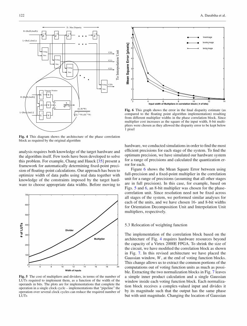
Fig. 6 This graph shows the error in the final disparity estimate (ascompared to the floating point algorithm implementation) resultingfrom different multiplier widths in the phase correlation block. Sincemultiplier cost increases as the square of the input width, 8-bit multi-pliers were chosen as they allowed the disparity error to be kept below1 pixel
hardware, we conducted simulations in order to find the mostefficient precisions for each stage of the system. To find theoptimum precision, we have simulated our hardware systemfor a range of precisions and calculated the quantization er-ror for each.
Figure 6 shows the Mean Square Error between usingfull-precision and a fixed-point multiplier in the correlationunit for a range of precisions (assuming that all other stagesare in full precision). In this case, for example, based onFigs. 5 and 6, an 8-bit multiplier was chosen for the phase-correlation unit. Since resolution need not be fixed acrossall stages of the system, we performed similar analyses foreach of the units, and we have chosen 16- and 8-bit widthsfor Orientation Decomposition Unit and Interpolation Unitmultipliers, respectively.
5.3 Relocation of weighting function
The implementation of the correlation block based on thearchitecture of Fig. 4 requires hardware resources beyondthe capacity of a Virtex 2000E FPGA. To shrink the size ofthe circuit, we have modified the correlation block as shownin Fig. 7. In this revised architecture we have placed theGaussian window, W , at the end of voting function blocks.This change allows us to extract the common portions of thecomputations out of voting function units as much as possi-ble. Extracting the two normalization blocks in Fig. 7 leavesa simple inner product calculation and a single Gaussianwindow inside each voting function block. Each normaliza-tion block receives a complex-valued input and divides itby its magnitude such that the output has the same phasebut with unit magnitude. Changing the location of Gaussian

Reconfigurable hardware implementation of a phase-correlation stereo algorithm 123
( From G2/H2Filters)
To
Inte
rpol
atio
n U
nit
-1-1-1
(L . R) * W^LPF^Prod.
^
D : Max Disparity
|| R ||
|| L ||L=
R=[Re(R), Im(R)]^
Cross W
Z Z Z
Corr.
Corr.Corr(D+1)
Corr.
R
L^
R=^
L=[Re(L),Im(L)]
R=[Re(R),Im(R)]
Corr(2)
Corr(1)
L=[Re(L), Im(L)]^^ ^
Norm.
Norm.
^
Fig. 7 Revised structure of the correlation block. Each complex valueis normalized before entering the correlation block, and the weightingfunction is applied after normalization and computation of the innerproduct
window along with sharing the normalization block reducesthe total number of multipliers, dividers and square rootsin the correlation unit by more than 65%. Since the output ofthe normalization blocks is in the limited range of [−1,+1],it is possible to use a small number of bits in representingtheir output. At present the output is 8 bits.
The drawback of this architecture is that the Gaussianwindow relocation to the end of voting function block isnot an exact analytical equivalent of the original method.In fact, by comparison with [31], it is seen that the revisedcomputation closely resembles a previously proposed phasedifferencing method, except that the difference function is
u2
A= =
A
A|| A ||u1
1 | Re(A) | + | Im(A) |
A
A
Im
Re
A
Re
Im
Au1
1
1 1
1
A= =
2Re(A) + Im(A)
22
A|| A ||
Au2
Fig. 8 The effect of using an L1 norm in computations instead of an L2 norm
now windowed and the voting structure has been retained.One can show that for FIR filters close to an impulse func-tion, this revision is a reasonable approximation [36] to theoriginal algorithm. Since in our stereo-vision system a 3-tapGaussian LP filter is used as W , this trade off seems to bereasonable.
5.4 Normalization of complex values
A further reduction in the size of the phase-correlation unit isachieved through modification of the architecture of the nor-malization block. This block is used to compute the magni-tude of the complex-valued inputs. The L2-norm of a com-plex number A is defined as ||A||2 = √�{A}2 + �{A}2.The hardware implementation of ||A||2 is expensive becauseit requires two multipliers, one square root and one adder.Instead, we replace it with the L1-norm of A, defined as||A||1 = |�{A}|+|�{A}|. Figure 8 shows the effect of using||A||1 instead of ||A||2 to normalize the output. When usingL2, all the normalized vectors are located on the unit circlein the Real-Imaginary plane, but in L1 they are projectedon a square as shown in Fig. 8. This is because the sum ofabsolute real and imaginary parts of L1-normalized vectorsis always unity and therefore they are projected to straightlines in each quadrant which form a square instead of a unitcircle. This technique provides enough accuracy for our ap-plication and may also be used in other applications requir-ing computation of vector norms. To improve the accuracyof the normalization operation and still avoid implementa-tion of ||A||2, there exists a different solution to the one weimplemented: since �{Au1} and �{Au1}, shown in Fig. 8,always lie between −1 and 1, one can use a memory blockas a look up table with appropriate values to replace currentAu1 vectors with corresponding points on unit circle. Theselook up tables can be built using on-chip memory, which isavailable in most current FPGA devices, without the need touse logic elements of the device. An example of the effectof replacing the L2 norm with an L1 norm in our system isgiven in Fig. 9.

124 A. Darabiha et al.
Fig. 9 This figure compares the performance of the L1 norm against that of the L2 norm. The differences between the two methods appearsminor, and can be characterized in a manner similar to quantization noise
Finally, it is worth considering the resource require-ments to implement an L2 norm. Each magnitude requires(i) computing �{A}2 + �{A}2, and then (ii) computingthe square root of this value. Step (i), assuming 16-bitmultipliers operating over four clock cycles, would requireroughly 200 4-LUTs. Step (ii) would require a further 7604-LUTs to compute the square root at the required precision.Since 12 magnitude units would be required, this entailsroughly 11,500 4-LUTs. While the FPGA implementing thephase correlation has 35,000 4-LUTs and only 16,709 areutilized, the chip is at 99% slice utilization, so it would notbe possible to implement the L2 magnitude units. While aCORDIC implementation [37, 38] would be possible andwould take less LUTs, the trade-off is LUTs for clock cyclesand the resulting design would not be fast enough, assumingenough slices were available.
5.5 Subpixel peak detection
Another modification made to the original algorithm is theaddition of a simple subpixel peak detection scheme. Oncethe integer-valued location of the voting function peak isfound, a quadratic function is fitted locally to the peak and itstwo neighboring values. This requires two shift operations,four additions and one division. Since the integer peak loca-tion can be encoded in five bits, we can encode the subpixelcorrection in three bits to end up with an 8-bit output. Othershave followed a similar procedure, for example Kanade et al.[11] perform the same interpolation on the C40 processor intheir system.
5.6 Data communication between FPGAs
As mentioned previously, our design is spread acrossfour FPGA devices mounted on a single circuit board. Adata path 98-bits wide exists between each pair of chips.We found that 98-bits was often not enough to trans-mit the required data between chips. For example in theScale/Orientation unit each image-pair has three pyramidlevels, with two orientations each, each producing both a
complex and real part, giving 24 16-bit values to be commu-nicated to the phase correlation unit. This requires 384 bitsto be transmitted for each clock cycle in the data pipeline.The transmission is achieved using a time-division multi-plexing (TDM) scheme. Since the overall system clock runsat 48 MHz, we have at least six time slices in which totransfer data and achieve an overall throughput of 8 MHz.It should be noted that the use of TDM comes with a cost, ashardware resources are required to buffer data on both sidesand manage the transfer.
6 Discussion
In Sect. 5 the implementation of the algorithm in FPGAhardware was described, and issues surrounding this im-plementation were discussed. In this section we evaluatethe performance of the implementation through compari-son with other stereo disparity implementations and throughcomparison with the original floating point software imple-mentation of the algorithm.
6.1 Imaging system
Image acquisition for the stereo system uses two Hitachi KP-D51 color CCD cameras, with a CCD size of 7.55 mm ×6.45 mm and 12 mm lenses. The cameras are rigidly fixedon a common mounting bracket, and there is a separationof 70 mm between the lens centers. In the stereo-vision sys-tem, the size of the phase-correlation and interpolation hard-ware design is directly proportional to the maximum dispar-ity that we specify between two images. We have set themaximum allowed disparity to 20 pixels. This correspondsto a minimum allowed distance of about 2 m from the objectsto the stereo head. Other parameters such as separation be-tween the cameras, CCD size and resolution can reduce theminimum distance, but they are usually restricted by opticaland physical constraints. For example, to reduce the mini-mum distance, wide-angle lenses can be used but lenses withsmaller focal length start to introduce radial distortion, thatwill degrade performance.

Reconfigurable hardware implementation of a phase-correlation stereo algorithm 125
Table 2 Comparison of PDS performance for various systems
Image size Disparity D Frame PDSn × m time (ms) (×106) Algorithm Platform
INRIA [9] 256 × 256 32 280 7.5 Intensity correlation PeRLe-1 board (23 XilinxXC3090 FPGAs
PARTS Engine [12] 240 × 320 24 23.8 77 Census 16 Xilinx 4025 FPGAsCMU Stereo Machine [11] 200 × 200 30 33 36 SAD Special purpose hardware
(c40 DSP + real-timeprocessor)
Yang/Pollefeysa [5] 512 × 512 20 71.4 58.9 multi-resolution SSD NVIDIA GeForce4Graphics card
Point Grey [25] 240 × 320 48 38.5 101.8 SAD 2.4 GHz P4This work 256 × 360 20 33 55.2 LWPC (phase correlation) TM-3A board (4 Xilinx
Virtex 2000E FPGAs)
aThis result is for a single image, and does not include real-time capture and rectification of images. The PDS value drops considerably when processing acaptured sequence.
6.2 Performance
The FPGA stereo system described in this paper performsmultiresolution, multiorientation disparity estimation basedon local weighted phase-correlation. It produces a dense dis-parity map of size 256 × 360 pixels with 8-bit subpixel ac-curacy disparity results at the rate of 30 fps. In the metric ofPoints × Disparity Estimates per second (PDS), this systemachieves a performance of 55.2 × 10⁶ PDS, which is amongthe highest rates reported [12]. Taking into account the rel-ative complexity of SAD vs. LWPC, the Point Grey resultseems less dominant. Table 2 compares several stereo-visionsystems. While the PDS metric reflects the density and thespeed of the system, it does not reflect the complexity or ac-curacy of the implemented algorithm. An important featureof our system in comparison with other hardware stereo ma-chines is its high-performance, phase-based algorithm. Torealize a phase-based algorithm in video rate, the systemperforms the equivalent of more than 10 billion 16 × 16-bitmultiplications per second and the four Virtex devices com-municate in a data rate of up to 200 Mbytes/s. Our algorithmis the most computationally complex stereo algorithm yetimplemented in hardware. The results given in Sect. 6.3 jus-tify the use of such a computationally intensive algorithm.
By comparison, the floating point version of the LWPCalgorithm, implemented in Matlab scripts, takes approxi-mately 30 s to compute disparity results for 256 × 360 im-ages when run on a Sun UltraSPARC-III 750 MHz worksta-tion with 2.5 GB of memory. While a comparison betweenhardware and an interpreted language may seem unfair, Mat-lab can be very computationally efficient so long as certainstructures, such as loops, are avoided (as they have been inour scripts). Porting it to C would result in some speed im-provement, perhaps a factor of ten, but certainly not enoughto make it anywhere near frame-rate.
The disparity output by the system is just the outputof the Peak-Detection unit without any postprocessing suchas left-to-right/right-to-left validation [39] or smoothing/gapfilling. Also, when the images are input to the system, theyare not preprocessed to achieve rectification, although this
should be done. We estimate that rectification and left-to-right/right-to-left validation can be added to the current sys-tem by increasing resources by approximately half of thesize of one Xilinx Virtex2000E FPGA. Given the capacityof FPGA devices now available, this poses no problem. Forexample, as suggested in [11], rectification can be imple-mented using a simple memory look-up to transform imagecoordinates before doing the phase-correlation. The trans-form values can be computed off-line using standard calibra-tion techniques and downloaded during the programming ofthe FPGAs. As another solution, rectification can be avoidedas prerectified images can be directly generated using spe-cial optical setups [40]. An efficient technique to integratethe left–right, right–left validation feature to the current sys-tem is to alternate between left and right images after eachsubsequent frame. Since left–right and right–left matching isperformed in different time slices, they can share the sameblocks and hence there is no need for extra hardware. Evenif we want to perform both matchings at the same time slice,we can still share the filtering blocks and need only imple-ment the correlation and peak detection separately.
6.3 Results
In this section we examine the accuracy of the system. Thiswill be done in two ways. First, we present stereo imagepairs for which “ground truth” (or a good, independent es-timate of it) is known. Results are presented for both asynthetic image pair containing a random-dot stereogramand also a real image-pair with hand measured depth at se-lected points. Our second method of evaluation will be tocompare the hardware performance against output of thefloating-point, software implementation of the LWPC algo-rithm. This will be done for several stereo-pairs commonlyused to evaluate stereo disparity algorithms. This compari-son uses images that have been previously rectified, and soremoves this source of error from the reported results.
Figure 10 shows the disparity map from a randomdot stereogram (RDS) extracted by the original LWPC

126 A. Darabiha et al.
Fig. 10 Comparison of the performance of the software version of LWPC against the performance of the hardware. The input is a random-dot stereogram image pair whose ground-truth disparity is shown in (a). The performance of the software implementation and the hardwareimplementation are shown in (b) and (c) respectively. While they are not identical, the differences are confined to the left-edges of the depthdiscontinuities which are expected to be noisy (see text)
algorithm and also by the hardware. The RDS was gener-ated by shifting blocks of pixels to the right. This explainsthe noise seen along the left edges of the disparity discon-tinuities: in these regions there are pixels that exist in oneimage but not the other, similar to occlusion that would beexperienced in real scenes. In these regions the phase corre-lation attempts to find matches for pixels where none exists,so we do not expect the algorithm to perform well. Left–right/right–left validation, currently not part of the system,would allow this type of error to be labeled as such [39]. Itshould also be noted that the algorithm does not include ei-ther a texture test or other false-matching tests, which wouldat least allow it to give a certainty measure for the estimatesproduced. Figure 11 shows a sample image from the camerahead and the depth map generated by the hardware.
In Table 3, the depth estimates obtained by our systemare compared with hand-measured depths. Since the hard-ware outputs disparity, and not depth, estimates, depths werecomputed according to
d = f T
D
Fig. 11 This figure compares the estimates of the hardware implementation against hand-measured ground truth shown in Table 3. In a is shownone of the original images from the pair used to generate the disparity map shown in b
where d is depth, f is the focal length of the imagingsystem, T is the baseline between the cameras, and D isthe disparity. Since we measure D in pixels, it is neces-sary to estimate the focal length in pixels via camera cal-ibration. This formula assumes that the cameras are per-fectly aligned, which of course they are not. A simple cal-ibration was performed to estimate the value of the prod-uct f T prior to making the estimates shown in Table 3. Asin most of the other stereo-matching algorithms, the phase-based stereo-matching algorithm is sensitive to depth dis-continuity and lack of texture. In regions with sufficient tex-ture, most of the depth measurement errors are less than3%, but in regions with little or no texture or at depthdiscontinuities, where occlusion and dis-occlusion becomean issue, the depth value estimates are less reliable. Anexample is the depth estimate for point 3 in Fig. 11a).This point lies on an occlusion boundary (where local al-gorithms are expected to do poorly, [24]), and inspectionof the disparity map (b) shows that it is obviously in er-ror. It is worth noting that despite the good results shownin Table 3, they would be even better if a full camera

Reconfigurable hardware implementation of a phase-correlation stereo algorithm 127
Table 3 Depth measurements for points labeled in Fig. 11
Point # 1 2 3 4 5
Ground truth depth (cm) 300 315 320 354 396Hardware depth estimate (cm) 309 (3%) 320 (1.6%) 276 (13.7%) 355 (0.3%) 402 (1.5%)
Fig. 12 Comparison of performance between the floating-point and fixed-point implementations of the algorithm. The disparities have beenrescaled to the range [0, 255] for display purposes. Since the hardware emulation result (c) includes subpixel peak detection, it shows a greaternumber of different disparity values than are evident in (b). Hardware emulation results without subpixel peak detection are shown in (d)
calibration had been performed and the images had beenrectified.
In Figs. 12 and 13, we see comparisons between thefloating point version of the algorithm, and the hardwareemulation. In these comparisons, we will see the effect ofchanges made to the algorithm, including the addition ofsubpixel peak detection. Figure 12 shows results from astereo pair where the disparity is in the range [−4, 4].2 Themeasured error (root mean square error) between the soft-ware and hardware-emulation disparities is about 0.49 pixels(0.52 pixels with subpixel disparity turned off). The agree-ment between the two implementations is very good, despitethe necessary changes in the hardware version.
2 Anytime results outside the range [0, 20] are quoted in this paper,the results are from an exact emulation of the fixed-point computationperformed by the hardware.
In Fig. 13, we see results from another stereo im-age pair, this time with disparities over a much largerrange, [−20, 20]. The RMSE between the software andhardware-emulation in this case is 3.09 pixels. The erroris 3.08 pixels with subpixel disparity turned off, since theoriginal algorithm does not include subpixel estimation.In Fig. 14 we see a histogram of the absolute values ofthe errors. The distribution has a dominant peak at zero,indicating that most pixels have an error less than 1 pixel.The distribution also has a long tail, which may indicatea uniform distribution of errors in cases where no goodmatch was found by either algorithm, but the software andhardware-emulation chose different values. In this sense theperformance of the hardware implementation is probablymuch better than the RMSE would suggest. Figure 14bshows the distribution of errors over the entire image,

128 A. Darabiha et al.
Fig. 13 Another test sequence is shown here. The left image from the original stereo pair is shown in (a), the disparity calculated by the floatingpoint version of the algorithm is shown in (b), and the hardware emulation version of the disparity is shown in (c)
Fig. 14 In (a) is shown the error distribution for the books test image. We see that the majority of the error is concentrated below 1 pixel, althoughthe distribution has a long tail. The root-mean-square error between the hardware emulator and the floating point versions is 3.09 pixels. Thereason for this large value is evident in Fig. 13, in the noisy section in the top-right corner. Both algorithms report disparity estimates varyingbetween ±20 in this region when it should be closer to zero. In some cases the floating point algorithm returns +20 when the hardware emulationreports −20, and vice versa. This leads to outliers in the error distribution, as can readily be verified from (b)
confirming that there are indeed localized regions in whichthe error is quite large, but that it is otherwise quite small.
In order to provide a further comparison of the hardwareimplementation with the original, floating-point LWPCimplementation, we used a standard test set of stereo-pairimages provided by Scharstein and Szeliski [24].3 Thesedata sets also allow for a direct comparison against otherstereo implementations. The results from three of these testsare shown in Figs. 15 and 16, and Table 4. It can be seen thatthe hardware implementation provides performance that iscomparable to the floating point version for the Sawtoothand Map images, although it performs somewhat worsefor the Tsukuba and Venus images. An error image and itsassociated error density for the Tsukuba image is shown in
3 These images, along with a numerical comparison with lead-ing stereo algorithms for the same data sets, can be found athttp://bj.middlebury.edu/ schar/stereo/web/results.php.
Fig. 16, and it is seen that much of the error again comesfrom attempting to match occluded pixels. The figures inTable 4 do not include occluded pixels (Fig. 16 does), butshows that nontextured regions and depth discontinuitiesare still problematic, as is to be expected with a correlation-based algorithm. For example, the lamp shade has verylow texture, and can be seen to have large disparity errorsin Fig. 16b). In all cases similar performance is found inthe discontinuity regions: while the performance is not thebest in either case, Scharstein and Szeliski admit that theseregions are expected to be troublesome for pure “local” al-gorithms [24]. The hardware implementation is consistentlypoorer on the untextured regions, but this is not unexpectedgiven the loss of fine detail through the fixed precision ofthe hardware system. In comparison with other algorithms,the hardware implementation delivered performance thatwas comparable to [19] and the Dynamic Programmingmethods [24] for the Venus and Map test images and [17]

Reconfigurable hardware implementation of a phase-correlation stereo algorithm 129
Table 4 Numerical results from the standard test images [24] from Fig. 15a
Tsukuba Sawtooth Venus MapAll Untex Disc All Untex Disc All Untex Disc All Disc
LWPC14.16 14.46 38.98 5.15 5.95 23.54 6.32 10.59 26.68 3.54 17.31
Hardware LWPC19.59 24.90 37.62 6.93 11.71 22.68 10.51 18.11 31.52 3.87 20.12
aValues indicate percentage of pixels with disparity error above one pixel.
Fig. 15 The comparative results of running the original LWPC algorithm along side the hardware for three images from Scharstein and Szekiski’sstandard test set [24]. The ground-truth disparities are shown in the first column. While the hardware results are “noisier” than the originalalgorithm, it is usually in regions where the original algorithm encountered difficulty. Numerical results are shown in Table 4
Fig. 16 In (a) is shown the error distribution for the Tsukuba test images. Again, the majority of the error is concentrated below 1 pixel, andthe distribution tail is again long. The absolute disparity error is shown in (b), with black representing zero (no error) and white representingmaximum error (10 pixels). It is evident that the algorithm has had difficulty at left-occlusion boundaries (the left image is used as reference),due to trying to match pixels that do not exist in the right image. The algorithm essentially guesses in these cases, giving rise to the distribution’srather flat tail. The root-mean-square error between hardware and the ground truth is 1.59 pixels

130 A. Darabiha et al.
for the Venus image. This is significant since none of theseare hardware implementations and all are much slower.No comparative data is known for the commercial stereosystems.
7 Conclusion
In summary, it should be seen that our system comparesfavorably with the systems described in Sect. 3. While someof the systems are starting to achieve frame rates above5 fps, none of them are doing the amount of computationthat our system is, and we expect our effective accuracy(assuming rectified images) to be significantly better. Forexample, while others are using correlation methods, noneare computing complex filter responses at multiple scalesand orientations, and then recovering and correlating thephase responses. While others are using image pyramidapproaches, they use the pyramid to simplify computation atsubsequent scales, as opposed to combining the informationacross scales. Finally, while we have attempted to comparerunning speeds of other algorithms based on the samesize of image that our system currently processes, it mustbe mentioned that we are able to handle larger images at30 fps if the algorithm is moved to larger FPGAs. Speedis thus dependent on the logic capacity of the FPGA, andnot just its clock speed. FPGAs with capacities greatlyexceeding that of the FPGAs used in this work nowexist.
This paper demonstrates the feasibility of implement-ing challenging vision applications on FPGAs to achieveframe-rate performance. It illustrates the trade-offs requiredfor a fast and efficient hardware implementation. Althoughthis paper is specifically focused on a particular phase-basedstereo-vision FPGA implementation, most of the design is-sues are common among other DSP and image-processingapplications. Many of the components of this system can bereused in other vision algorithms. prefiltering and buildingthe image pyramid are basic operations used by many algo-rithms doing tasks such as stereo, motion analysis and objectrecognition and localization. In particular, our implementa-tion of steerable filters has great potential for reuse. Exam-ples of algorithms based on these filters include optic flowcomputation [41, 42], object tracking [43] and recovery ofrotation and illumination invariant features [44], which canbe used for object tracking and/or object recognition. Theimplementation of the correlation units can be adapted foruse in other systems that require correlation, such as tem-plate matching.
Finally, it must be acknowledged that the LWPC algo-rithm is not among the top performers in the Middleburycomparative results. At the time this system was conceivedthis comparative data was not available, and had it been adifferent choice of algorithm might have been considered.However, in defense of the system, it has given rise to a num-ber of components that can be reused in other vision systems(as noted in the preceding paragraph).
7.1 Future work
A number of avenues for future work exist. The mostobvious is porting this system to larger FPGA devicesthat would allow for restoring the third orientation to theScale/Orientation unit, add preprocessing to rectify the im-age, and postprocessing to perform validation tasks such asleft–right/right–left validation on the output. The size of im-ages that can be processed will be increased, and compu-tation of a confidence measure for each disparity estimateshould be included. This measure can be based in part onestimates of local texture energy and probability of falsematches. Given the increase in capacity in newer FPGA de-vices these goals should not be difficult to accomplish.
Another improvement is to increase the range of alloweddisparities, and this work (along with the items mentionedin the previous paragraph) has already begun [45]. Althoughthis could be achieved by merely increasing hardware re-sources, there are other possible solutions. One solution toincreasing the system’s disparity range lies in preshiftingthe phase correlation to cover the expected range of dispar-ity for a particular section of the image. Between succes-sive frames, the expected disparity is not expected to changerapidly, so disparity values from the previous frame could beused to determine the required amount of prewarping for in-dividual pixels. At present the system has no memory of theresults from the previous frame when starting computationson a new image pair.
We would also like to look into methods to automate thesearch for optimal fixed-point widths. This could be donethrough exhaustive search over a predetermined range ofbit-widths, or through a simplified search where each stagein the pipeline is optimized on its own, assuming previousstages have already been optimized and subsequent stagesare still in floating point (this approach lends itself wellto the hardware-emulation stage). Also, it should be possi-ble to simultaneously optimize with respect to target devicespace limitations; this will require development of integratedfixed-point width search and synthesis/place & route algo-rithms.
Finally, recent advancements in FPGA technology havemade it possible to include simple processor cores to runsoftware within an FPGA device. Such processors can becustomized for a particular application, and are well suitedfor higher-level control tasks. The application of such coresto implementations of vision algorithms warrants further in-vestigation.
Acknowledgements The authors would like to thank Marcus VanIerssel and David Galloway for their technical assistance during thecourse of this work, and Allan Jepson for his thoughts and sugges-tions. The authors would also like to acknowledge financial supportfrom Micronet R&D and NSERC.
References
1. Fleet, D.J.: Disparity from local weighted phase correlation. Int.Conf. Syst. Man Cybernetics 1, 48–54 (1994)

Reconfigurable hardware implementation of a phase-correlation stereo algorithm 131
2. Xilinx Inc.: Design tools center, cited May 3, 2005. [Online].Available: http://www.xilinx.com/products/design resources/design tool/index.htm
3. Altera Corporation: DSP Builder, cited May 3, 2005 [Online].Available: http://www.altera.com/products/software/products/dsp/dsp-builder.html
4. Fung, J., Mann, S.: Using multiple graphics cards as a gen-eral purpose parallel computer: Applications to computer vision.In: Proceedings of the 17th International Conference on Pat-tern Recognition, Cambridge, UK, pp. 805–808 (2004) online:http://www.eyetap.org/papers/docs/procicpr2004/
5. Yang, R., Pollefeys, M.: Multi-resolution real-time stereo on com-modity graphics hardware. In: Proceedings of the 2003 IEEEConference on Computer Vision and Pattern Recognition, vol. 1,Madison, Wisconsin, pp. 211–218 (2003) [Online]. Available:http://citeseer.ist.psu.edu/article/yang03multiresolution.html
6. van Ierssel, M.: TM-3 documentation (2002) [Online]. Available:http://www.eecg.toronto.edu/ tm3/
7. van Ierssel, M., Galloway, D., Chow, P., Rose, J.: The Transmo-grifier 3-a: Hardware and software for a 3 million gate rapid pro-totyping system. In: Micronet Annual Workshop (2001)
8. Xilinx Inc.: Xilinx data sheets (2002) [Online]. Available: http://direct.xilinx.com/bvdocs/publications/ds022-1.pdf
9. Faugeras, O., Hotz, B., Mathieu, H., Vieville, T., Zhang, Z., Fua,P., Theron, E., Moll, L., Berry, G., Vuillemin, J., Bertin, P., Proy,C.: Real time correlation-based stereo: Algorithm, implementa-tions and applications. INRIA Sophia Antipolis, Tech. Rep. Re-search Report 2013 (1993) [Online]. Available: ftp://ftp.inria.fr/INRIA/publication/publi-ps-gz/RR/RR-2013.ps.gz
10. Hou, K.M., Belloum, A.: A reconfigurable and flexible paral-lel 3d vision system for a mobile robot. In: IEEE Workshopon Computer Architecture for Machine Perception New Orleans,Louisiana (1993)
11. Kanade, T., Yoshida, A., Oda, K., Kano, H., Tanaka, M.: A stereomachine for video-rate dense depth mapping and its new applica-tions. In: Proceedings of the 15th IEEE Computer Vision & Pat-tern Recognition Conference, pp. 196–202. San Francisco (1996)
12. Woodfill, J., Herzen, B.V.: Real time stereo vision on the parts re-configurable computer. In: 5th Annual IEEE Symposium on Field-Programmable Custom Computing Machines, pp. 201–210 (1997)
13. Zabih, R., Woodfill, J.: Non-parametric local transforms forcomputing visual correspondence. In: Proceedings of the 3rdEuropean Conference on Computer Vision, pp. 150–158 (1994)http://www.cs.cornell.edu/rdz/Papers/Archive/neccv.ps, http://www.cs.cornell.edu/rdz/Papers/Archive/nplt-journal.ps.gz
14. Burt, P.J.: A pyramid-based front-end processor for dynamic vi-sion applications. In: Proceedings of the IEEE 90(7), 1188–1200(2002)
15. van der Wal, G., Hansen, M., Piacentino, M.: The acadia visionprocessor. In: Proceedings of the Fifth IEEE International Work-shop on Computer Architecture for Machine Perception, pp. 31–40. Padua, Italy (2000)
16. Hirschmuller, H., Innocent, P.R., Garibaldi, J.: Real-timecorrelation-based stereo vision with reduced border errors. Int. J.Comput. Vis. 47(1–3), 229–246 (2002), stereo, intensity correla-tion, MMX, fast
17. Muhlmann, K., Maier, D., Hesser, J., Anner, R.M.: Calculatingdense disparity maps from color stereo images, an efficient im-plementation. Int. J. Comput. Vis. 47(1–3), 79–88 (2002), stereo,intensity correlation, MMX, fast
18. Mulligan, J., Isler, V., Daniilidis, K.: Trinocular stereo: A real-timealgorithm and its evaluation. Int. J. Comput. Vis. 47(1–3), 51–61(2002), stereo, trinocular, DFW-V500
19. Sun, C.: Fast stereo matching using rectangular subregioning and3d maximum-surface techniques. Int. J. Comput. Vis. 47(1–3),99–117 (2002)
20. Veksler, O.: Stereo correspondence with compact windows viaminimum ratio cycle. IEEE Trans. Pattern Anal. Machine Intell.24(12), 1654–1660 (2002)
21. Burt, P., Adelson, E.: The laplacian pyramid as a compact imagecode. IEEE Trans. Commun. 31, 532–540 (1983)
22. Meerbergen, G.V., Vergauwen, M., Pollefeys, M., Gool, L.V.: Ahierarchical symmetric stereo algorithm using dynamic program-ming. Int. J. Comput. Vis. 47(1–3), 275–285 (2002)
23. Birchfield, S., Tomasi, C.: Depth discontinuities by pixel-to-pixelstereo. Int. J. Comput. Vis. 35(3), 269–293 (1999)
24. Scharstein, D., Szeliski, R.: A taxonomy and evaluation of densetwo-frame stereo correspondence algorithms. Int. J. Comput. Vis.47(1–3), 7–42 (2002)
25. Point Grey Research: Point Grey Research homepage. cited May3, 2005 [Online]. Available: http://www.ptgrey.com/
26. Videre Design: SRI small vision system, cited May 3, 2005 [On-line]. Available: http://www.videredesign.com/svs.htm
27. Konolige, K.: Small vision systems: Hardware and implenta-tion. In: Proceedings of the Eighth International Symposiumon Robotics Research (Robotics Research 8), Hayama, Japan,pp. 203–212 (1997) [Online]. Available: citeseer.ist.psu.edu/konolige97small.html
28. Canesta Inc.: Canesta ep development kit. cited May 3, 2005. [On-line]. Available: http://www.canesta.com/devkit.htm
29. Baker, H.H., Binford, T.O.: Depth from edges and intensity basedstereo. In: Proceedings of the 7th International Joint Conferenceon Artificial Intelligence, pp. 631–636. Vancouver (1981)
30. Ayache, N., Faverjon, B.: Efficient registration of stereo imagesby matching graph descriptions of edge segments. Int. J. Comput.Vis. 1(2), 107–131 (1987)
31. Fleet, D.J., Jepson, A.D., Jenkin, M.R.M.: Phase-based dispar-ity measurement. CVGIP: Image Understanding 53(2), 198–210(1991)
32. Wang, J.J.: Image matching using the windowed fourier phase. Int.J. Comput. Vis. 11(3), 211–236 (1993), read
33. Freeman, W.T., Adelson, E.H.: The design and use of steerablefilters. IEEE Trans. Pattern Anal. Mach. Intell. 13(9), 891–906(1991)
34. Trucco, E., Verri, A.: Introductory Techniques for 3-D ComputerVision. Prentice Hall (1998)
35. Chang, M.L., Hauck, S.: Precis: A design-time precisionanalysis tool. In: 10th Annual IEEE Symposium on Field-Programmable Custom Computing Machines, pp. 229–283 (2002)[Online]. Available: http://www.ee.washington.edu/faculty/hauck/publications/PrecisFCCM2002
36. Darabiha, A.: Video-rate stereo vision on reconfigurable hard-ware. Master’s thesis, Department of Electrical & Computer En-gineering, University of Toronto (2003)
37. Andraka, R.: A survey of CORDIC algorithms for FPGAs. In:Proceedings of the 1998 ACM/SIGDA Sixth International Sympo-sium on Field Programmable Gate Arrays (FPGA ’98), Monterey,CA, pp. 191–200 (1998) [Online]. Available: http://www.andraka.com/files/crdcsrvy.pdf
38. Valls, J., Kuhlmann, M., Parhi, K.K.: Evaluation of CORDIC al-gorithms for FPGA design. J. VLSI Signal Process. 32, 207–222(2002)
39. Fua, P.: A parallel stereo algorithm that produces dense depthmaps and preserves image features. Mach. Vis. & Appl. 6(1), 35–49 (1993), INRIA Research Report 1369
40. Gluckman, J., Nayar, S.K.: Rectified catadioptric stereo sensors.IEEE Trans. Pattern Anal. Machine Intell. 24(2), 224–236 (2002),stereo, mirros, rectified
41. Fleet, D.J., Black, M.J., Jepson, A.D.: Motion feature detection us-ing steerable flow fields. In: Proceedings of the 1998 IEEE Com-puter Society Conference on Computer Vision and Pattern Recog-nition, pp. 274–281. Santa Barbara (1998)

132 A. Darabiha et al.
42. Fleet, D.J., Jepson, A.D.: Computation of component image veloc-ity from local phase information. Int. J. Comput. Vis. 5(1), 77–104(1990)
43. Jepson, A.D., Fleet, D.J., El-Maraghi, T.F.: Robust on-lineappearance models for visual tracking. In: IEEE Conference onComputer Vision and Pattern Recognition, vol. 1, pp. 415–422Kauai, (2001) [Online]. Available: http://www.cs.toronto.edu/ tem/cvpr01.pdf
44. Carneiro, G., Jepson, A.D.: Local phase-based features. In: Pro-ceedings of the 2002 European Conference on Computer Vision,vol. 1, pp. 282–296. Copenhagen, Denmark (2002)
45. Masrani, D.K., MacLean, W.J.: Expanding disparity range in anFPGA stereo system while keeping resource utilization low. In:The First IEEE Workshop on Embedded Computer Vision, CVPR2005 (2005)