recommendations on the transport of dangerous goods manual of tests and criteria
TRANSCRIPT

Recommendations on the
TRANSPORT OF DANGEROUS GOODS Manual of Tests and Criteria Fifth revised edition Amendment 1
UNITED NATIONS


ST/SG/AC.10/11/Rev.5/Amend.1
Recommendations on the
TRANSPORT OF DANGEROUS GOODS Manual of Tests and Criteria
Fifth revised edition Amendment 1
UNITED NATIONS New York and Geneva, 2011

NOTE
The designations employed and the presentation of the material in this publication do not imply the expression of any opinion whatsoever on the part of the Secretariat of the United Nations concerning the legal status of any country, territory, city or area, or of its authorities, or concerning the delimitation of its frontiers or boundaries.
ST/SG/AC.10/11/Rev.5/Amend.1
Copyright © United Nations, 2011
All rights reserved.
No part of this publication may, for sales purposes, be reproduced, stored in a retrieval system or transmitted in any form or by any means, electronic, electrostatic, magnetic tape, mechanical,
photocopying or otherwise, without prior permission in writing from the United Nations.
UNITED NATIONS PUBLICATION Sales No. E.11.VIII.2
ISBN 978-92-1-139142-8 e-ISBN 978-92-1-055138-0
- iii -
FOREWORD
The Manual of Tests and Criteria contains criteria, test methods and procedures to be used for classification of dangerous goods according to the provisions of Parts 2 and 3 of the United Nations Recommendations on the Transport of Dangerous Goods, Model Regulations1, as well as of chemicals presenting physical hazards according to the Globally Harmonized System of Classification and Labelling of Chemicals (GHS)2. As a consequence, it supplements also national or international regulations which are derived from the United Nations Recommendations on the Transport of Dangerous Goods or the GHS. Originally developed by the Economic and Social Council’s Committee of Experts on the Transport of Dangerous Goods which adopted a first version in 1984, it has been regularly updated and amended every two years. Presently, the updating is done under the auspices of the Committee of Experts on the Transport of Dangerous Goods and on the Globally Harmonized System of Classification and Labelling of Chemicals, which replaces the original committee since 2001. The fifth revised edition, published in 2009, includes all the amendments to the fourth revised edition adopted by the Committee at its second and third sessions in 2004 and 2006 (published under the symbols ST/SG/AC.10/11/Rev.4/Amend.1 and ST/SG/AC.10/11/Rev.4/Amend.2) and those adopted at its fourth session in 2008 (ST/SG/AC.10/36/Add.2 and -/Corr.1).
The amendments listed in this publication were adopted by the Committee at its fifth session (10 December 2010)3. This publication also include the corrections adopted by the Sub-Committee of Experts on the Transport of Dangerous at its thirty-ninth session (20-24 June 2011)4. The amendments listed include:
- Amendments to the procedure for assignment to a Division of Class 1;
- Amendments to test series 7 for the classification as extremely insensitive explosive article;
- A test method for the classification of gases and gas mixtures as chemically unstable (new section 35);
- Amendments to the procedures to be followed for the classification of lithium metal and lithium ion cells and batteries;
- Amendments to the variations permitted for MEGCs design without additional testing;
- A new appendix 8 detailing the response descriptors to be used for the purposes of Test series 7.
1 ST/SG/AC.10/1/Rev.17. United Nations publication, sales No. E.11.VIII.1. 2 ST/SG/AC.10/30/Rev.4. United Nations publication, sales No. 11.II.E.6. 3 ST/SG/AC.10/38/Add.2. 4 ST/SG/AC.10/C.3/78, Annex IV.


- v -
TABLE OF CONTENTS ................... Page AMENDMENTS TO THE GENERAL INTRODUCTION Section 1 ................................................................................................. 1 AMENDMENTS TO PART I OF THE MANUAL Section 10 ................................................................................................. 1 Section 17 ................................................................................................. 15 AMENDMENTS TO PART III OF THE MANUAL Section 35 ................................................................................................. 36 Section 38 ................................................................................................. 43 AMENDMENTS TO PART IV OF THE MANUAL................................................................. Section 41 ................................................................................................. 52 NEW APPENDIX Appendix 8 ................................................................................................. 53

- 1 -
AMENDMENTS TO THE FIFTH REVISED EDITION OF THE MANUAL OF TESTS AND CRITERIA
GENERAL INTRODUCTION SECTION 1 In Table 1.2, replace "EIDS" with "EIS" wherever it appears. PART I OF THE MANUAL SECTION 10 10.4 replace current sub-section 10.4 with the following: "10.4 Procedure for assignment to a division of Class 1 10.4.1 General description 10.4.1.1 Goods of Class 1 are assigned to one of six divisions, depending on the type of hazard they present (see paragraph 2.1.1.4 of the Model Regulations). The assignment procedure (Figure 10.3) applies to all substances and/or articles that are candidates for Class 1 except those declared from the outset to be in Division 1.1. A substance or article should be assigned to the division which corresponds to the results of the tests to which the substance or article, as offered for transport, has been subjected. Other test results, and data assembled from accidents which have occurred, may also be taken into account. As indicated in box 36 of Figure 10.3, there is authority to exclude an article from Class 1 by virtue of test results and the Class 1 definition. 10.4.2 Test types 10.4.2.1 The test methods used for assignment to a division are grouped into three series - numbered 5 to 7 - designed to provide the information necessary to answer the questions in Figure 10.3. The tests in series 5, 6 and 7 should not be varied unless the national authority is prepared to justify such action internationally. 10.4.2.2 The results from three types of series 5 tests are used to answer the question "Is it a very insensitive explosive substance with a mass explosion hazard?" (box 21, Figure 10.3). The test types are: Type 5 (a): a shock test to determine the sensitivity to intense mechanical stimulus; Type 5 (b): thermal tests to determine the tendency for transition from deflagration to
detonation; and Type 5 (c): a test to determine if a substance, when in large quantities, explodes when
subjected to a large fire.

- 2 -
Figure 10.3: PROCEDURE FOR ASSIGNMENT TO A DIVISION OF CLASS 1
Is the major
hazard radiant heat and/or violent burning
but with no dangerous blast or projection hazard?
No
No
ARTICLE OR SUBSTANCE PROVISIONALLY ACCEPTED INTO CLASS 1 (from figure 10.2)
Yes
TEST SERIES 5
Yes
Yes
No
No
No
No
Is the article a candidate for Division 1.6?
24
TEST SERIES 7
39
Is it an extremely insensitive
article?
40
Is the substance a candidate
for Division 1.5?
19
20
Is it a very insensitive
explosive substance with a mass explosion
hazard?
21
Package the substance
23
TEST SERIES 6
25
Is the result a mass explosion?
26
Is the major hazard that from dangerous
projections?
28
30
32
33
Is the substance or article
manufactured with the view of producing a practical explosive
or pyrotechnic effect?
35
Is the product an article
excluded by definition? (see Model Regulations, par.
2.1.1.1 (b))
36
NOT CLASS 1
38
DIVISION 1.6
41
DIVISION 1.5
22 DIVISION 1.4 Compatibility
group S
37
DIVISION 1.4 Compatibility groups
other than S
34
DIVISION 1.3
31
DIVISION 1.2
29
DIVISION 1.1
27
Yes
Yes
Yes
Yes
Yes
No
No
Yes
Yes Yes
No
No
No
Would the hazard hinder fire-fighting in the
immediate vicinity?
Are there hazardous effects
outside the package?

- 3 -
Figure 10.4: PROCEDURE FOR AMMONIUM NITRATE EMULSION, SUSPENSION OR GEL, INTERMEDIATE FOR BLASTING EXPLOSIVES
Test 8 (b) ANE Large Scale Gap Test
Is the substance too sensitive to shock to be accepted in
Division 5.1?
Test Series 8 (from Figure 10.2)
Test 8(a) Thermal Stability Test
Is the substance thermally stable?
Substance accepted in Division 5.1 as an ammonium nitrate emulsion, suspension or gel, intermediate for blasting explosives (ANE)
No
Yes
No
REJECT Substance not stable for transport
REJECT Substance to be considered for inclusion into Class 1; if the answer in box 21 of Figure 10.3 is “no”, the substance shall be classified under UN 0241
Substance to be considered as a candidate for Division 1.5, proceed with Test Series 5. If the answer to box 21 of Figure 10.3 is “yes” the substance shall be classified under UN 0332, if “no” the substance shall be classified under UN 0241
No
Yes
Yes
Test 8 (c) Koenen Test
Is the substance too sensitive to the effect of heating under
confinement?

- 4 -
Figure 10.5: PROCEDURE TO DETERMINE REQUIRED SUBSTANCE TESTING FOR DIVISION 1.6
Is the substance
in a component of a fuze with two or more independent effective protective features or in a boostering
component?
Undertake and meet acceptance criteria of extremely insensitive substance tests
Type 7 (a) to 7 (f)
Each explosive substance in a Division 1.6 candidate article design
Undertake and meet acceptance criteria of explosive substance tests
Type 7 (c) (ii) and 7(e)
No
2
1
4
3
Yes
Yes
Yes 6
Is the substance in a boostering component that exceeds a cross-sectional dimension of 50 mm
or 5% volume when compared to its main
explosive load?
No
9 No
5
7
Type 7 (a) to 7 (f) testing not required Reject from Division 1.6
Yes
Is the substance in an isolated auxiliary explosive
component of the article, which when ignited or initiated
does not cause any reaction of the main explosive loads?
Is the substance in a main explosive load of a component within the article?
No
8

- 5 -
10.4.2.3 The results from four types of series 6 tests are used to determine which division, amongst Divisions 1.1, 1.2, 1.3 and 1.4, corresponds most closely to the behaviour of a product if a load is involved in a fire resulting from internal or external sources or an explosion from internal sources (boxes 26, 28, 30, 32 and 33 of Figure 10.3). The results are also necessary to assess whether a product can be assigned to Compatibility Group S of Division 1.4 and whether or not it should be excluded from Class 1 (boxes 35 and 36 of Figure 10.3). The four types of test are:
Type 6 (a): a test on a single package to determine if there is mass explosion of the contents;
Type 6 (b): a test on packages of an explosive substance or explosive articles, or non-packaged explosive articles, to determine whether an explosion is propagated from one package to another or from a non-packaged article to another;
Type 6 (c): a test on packages of an explosive substance or explosive articles, or non-packaged explosive articles, to determine whether there is a mass explosion or a hazard from dangerous projections, radiant heat and/or violent burning or any other dangerous effect when involved in a fire; and
Type 6 (d): a test on an unconfined package of explosive articles to which special provision 347 of Chapter 3.3 of the Model Regulations applies, to determine if there are hazardous effects outside the package arising from accidental ignition or initiation of the contents.
10.4.2.4 The question "Is it an extremely insensitive explosive article?" (box 40, Figure 10.3) is answered by series 7 tests and any candidate for Division 1.6 should be assessed against each of the eleven types of test comprising the series. The protocol for determining the test requirements is given in Figure 10.5. The first six types of test (7(a) to 7(f)) are used to establish if a substance is an Extremely Insensitive Substance (EIS). The purpose of these tests is to develop an understanding of the sensitivity of substance(s) contained within the article, which informs and provides confidence in the article tests. The remaining five types of test (7(g), 7(h), 7(j), 7(k) and 7 (l)) are used to determine if an article predominantly containing EIS may be assigned to Division 1.6. The eleven test types are:
Type 7 (a): a shock test to determine the sensitivity to intense mechanical stimulus;
Type 7 (b): a shock test with a defined booster and confinement to determine the sensitivity to shock;
Type 7 (c): a test to determine the sensitivity of the explosive substance to deterioration under the effect of an impact;
Type 7 (d): a test to determine the degree of reaction of the explosive substance to impact or penetration resulting from a given energy source;
Type 7 (e): a test to determine the reaction of the explosive substance to an external fire when the material is confined;
Type 7 (f): a test to determine the reaction of the explosive substance in an environment in which the temperature is gradually increased to 365 °C;
Type 7 (g): a test to determine the reaction to an external fire of an article which is in the condition as presented for transport;
Type 7 (h): a test to determine the reaction of an article in an environment in which the temperature is gradually increased to 365 °C;
Type 7 (j): a test to determine the reaction of an article to impact or penetration resulting from a given energy source;

- 6 -
Type 7 (k): a test to determine whether the detonation of an article will initiate a detonation in an adjacent, like, article; and
Type 7 (l): a test to determine the sensitivity of an article to shock directed at vulnerable components.
10.4.2.5 The question "Is the substance a candidate for "ammonium nitrate emulsion or suspension or gel, intermediate for blasting explosives (ANE)?" (box 2(a), Figure 10.2) is answered by series 8 tests and any candidate should pass each of the three tests comprising the series. The three test types are:
Type 8 (a): a test to determine the thermal stability;
Type 8 (b): a shock test to determine sensitivity to intense shock;
Type 8 (c): a test to determine the effect of heating under confinement;
Test series 8 (d) has been included in this section as one method to evaluate the suitability for the transport in tanks.
10.4.3 Application of the test methods
10.4.3.1 Explanations of certain terms used in the assignment of divisions and compatibility groups are given in the Glossary in Appendix B of the Model Regulations (e.g. mass explosion, pyrotechnic substance, entire load, total contents, explode, explosion of the total contents).
10.4.3.2 Test series 5 should be used to determine whether a substance can be assigned to Division 1.5. Only those substances which pass all three types of test may be assigned to Division 1.5.
10.4.3.3 Test series 6 should be applied to packages of explosive substances and articles in the condition and form in which they are offered for transport. The geometrical arrangement of the products should be realistic in regard to the packing method, and the conditions of transport, and should be such as to produce the most disadvantageous test results. Where explosive articles are to be carried without packaging, the tests should be applied to the non-packaged articles. All types of packaging containing substances or articles should be subjected to the tests unless:
(a) The product, including any packaging, can be unambiguously assigned to a division by the competent authority on the basis of results from other tests or of available information; or
(b) The product, including any packaging, is assigned to Division 1.1.
10.4.3.4 Test types 6 (a), 6 (b), 6 (c) and 6 (d) are performed in alphabetical order. However, it is not always necessary to conduct all four types of test. Test type 6 (a) may be waived if explosive articles are carried without packaging or when only one article is in the package. Test type 6 (b) may be waived if, in each type of 6 (a) test:
(a) The exterior of the package is undamaged by internal detonation and/or ignition; or
(b) The contents of the package fail to explode, or explode so feebly as would exclude propagation of the explosive effect from one package to another in test type 6 (b).
Test type 6 (c) may be waived if, in a type 6 (b) test, there is a practically instantaneous explosion of virtually the total contents of the stack. In such cases the product is assigned to Division 1.1.
Test type 6 (d) is a test used to determine whether a 1.4S classification is appropriate and is only used if special provision 347 of Chapter 3.3 of the Model Regulations applies.

- 7 -
The results of test series 6 (c) and 6 (d) indicate if 1.4S is appropriate, otherwise the classification is 1.4 other than S.
10.4.3.5 If a substance gives a "—" result (no propagation of detonation) in the Series 1 type (a) test, the 6 (a) test with a detonator may be waived. If a substance gives a "—" result (no or slow deflagration) in a Series 2 type (c) test, the 6 (a) test with an igniter may be waived.
10.4.3.6 Tests types 7 (a) to 7 (f) should be used to establish that a substance is an extremely insensitive substance and then test types 7 (g), 7 (h), 7 (j), 7 (k) and 7 (l) used to establish that the articles predominantly containing EIS(s) may be assigned to Division 1.6.
10.4.3.7 Tests of types 7 (g), 7 (h), 7 (j), 7 (k) and 7(l) should be performed to determine if an article with EIS main explosive load(s) and appropriately insensitive boostering components may be assigned to Division 1.6. These tests are applied to articles in the condition and form in which they are offered for transport, except that non-explosive components may be omitted or simulated if the competent authority is satisfied that this does not invalidate the results of the tests. The procedure detailing testing requirements is given in Figure 10.5 and some points of explanation are given below.
(a) Complex articles may contain multiple substances and this procedure should be completed for all substances within the article to be classified.
(b) The question "Is the substance in a main explosive load of a component within the article?" (Box 2 of Figure 10.5) is answered by examining the design of the article. Main explosive load substances are those loaded into components within the article that are not fuze, boostering, or isolated auxiliary explosive components. All substances in main explosive loads must "Undertake and meet acceptance criteria of extremely insensitive substance tests, Type 7 (a) to 7 (f)" (Box 3 of Figure 10.5). If a ‘+’ result is obtained for any main explosive load substance to any Type 7 (a) to 7 (f) test, the substance is not an EIS and the answer to the question in Box 24 of Figure 10.3 is "No". The article is not a candidate for Division 1.6.
(c) Answering the question "Is the substance in an isolated auxiliary explosive component of the article, which when ignited or initiated does not cause any reaction of the main explosive loads?" (Box 4 of Figure 10.5) requires knowledge of the design of the article plus the explosive effects that occur when such components are initiated or ignited, either in their design mode or accidentally. Typically these will be small explosive actuators or pyromechanical devices that produce movement, cutting or opening functions. If the answer is ‘yes’ to this question, Type 7 (a) to 7 (f) testing is not required for substances in isolated auxiliary explosive components and the article remains a candidate for Division 1.6.
(d) The question "Is the substance in a boostering component that exceeds a cross-sectional dimension of 50 mm or 5% volume when compared to its main explosive load?" (Box 6 of Figure 10.5) is answered by examining the design of the article. All substances in such larger boostering components, including those contained in explosive components of dual-protected fuzes in an article, must "Undertake and meet acceptance criteria of explosive substance tests, Type 7 (c) (ii) and 7 (e)" (box 7 of Figure 10.5). If a ‘+’ result is obtained for any such larger boostering component substance to either Type 7 (c) (ii) and 7 (e) tests, the answer to the question in Box 24 of Figure 10.3 is "No". The article is not a candidate for Division 1.6.
(e) The question "Is the substance in a component of a fuze with two or more independent effective protective features or in a boostering component" (Box 8 of Figure 10.5) is answered by an understanding of the design and development of the article. If the answer is ‘no’, the article is not considered to have suitable intrinsic safety characteristics and the answer to the question in Box 24 of Figure 10.3 is ‘No’ the article is not a candidate for Division 1.6.

- 8 -
NOTE: Knowledge of the design and explosive effects can be obtained by modelling or indicative tests etc.
10.4.3.8 Test types 8 (a) to 8 (c) should be used to establish whether an ammonium nitrate emulsion or suspension or gel, intermediate for blasting explosives (ANE) may be assigned to Division 5.1. Substances failing any of the tests may be considered as a candidate for Class 1 in accordance with Figure 10.4.
10.4.3.9 If articles contain expensive, inert, control components, these may be replaced by inert components having a similar mass and volume.
10.5 Examples of test reports
10.5.1 Examples of test reports, with an illustration of the use of the flow charts on the application of the Class 1 acceptance and assignment procedures to musk xylene (UN 2956), are given in figures 10.6 to 10.9.
10.5.2 An example proforma for a test report on articles is given in Figure 10.10.

- 9 -
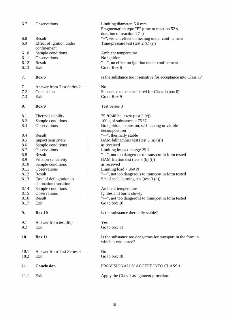
Figure 10.6: RESULTS FROM APPLICATION OF THE CLASS 1 ACCEPTANCE PROCEDURE 1. Name of substance : 5-tert-BUTYL-2,4,6-TRINITRO-m-XYLENE (MUSK XYLENE) 2. General data 2.1 Composition : 99% tert-butyl-2,4,6-trinitro-m-xylene 2.2 Molecular formula : C12H15N3O6 2.3 Physical form : Fine crystalline powder 2.4 Colour : Pale yellow 2.5 Apparent density : 840 kg/m3 2.6 Particle size : < 1.7 mm 3. Box 2 : Is the substance manufactured with the view to producing a practical explosive or pyrotechnic effect? 3.1 Answer : No 3.2 Exit : Go to Box 3 4. Box 3 : Test Series 1 4.1 Propagation of Detonation : UN gap test (test 1(a)) 4.2 Sample conditions : Ambient temperature 4.3 Observations : Fragmentation length 40 cm 4.4 Result : "+", propagation of detonation 4.5 Effect of heating under : Koenen test (test 1(b)) confinement 4.6 Sample conditions : Mass 22.6 g 4.7 Observations : Limiting diameter 5.0 mm Fragmentation type "F" (time to reaction 52 s, duration of reaction 27 s) 4.8 Result : "+", shows some explosive effects on heating under confinement 4.9 Effect of ignition under : Time/pressure test (test 1 (c) (i)) confinement 4.10 Sample conditions : Ambient temperature 4.11 Observations : No ignition 4.12 Result : "—", no effect on ignition under confinement 4.13 Exit : Go to Box 4 5. Box 4 : Is it an explosive substance? 5.1 Answer from Test Series 1 : Yes 5.2 Exit : Go to box 5 6. Box 5 : Test Series 2 6.1 Sensitivity to shock : UN gap test (test 2(a)) 6.2 Sample conditions : Ambient temperature 6.3 Observations : No propagation 6.4 Result : "—", not sensitive to shock 6.5 Effect of heating under : Koenen test (test 2(b)) confinement 6.6 Sample conditions : Mass 22.6 g
- 10 -
6.7 Observations : Limiting diameter 5.0 mm Fragmentation type "F" (time to reaction 52 s, duration of reaction 27 s) 6.8 Result : "+", violent effect on heating under confinement 6.9 Effect of ignition under : Time/pressure test (test 2 (c) (i)) confinement 6.10 Sample conditions : Ambient temperature 6.11 Observations : No ignition 6.12 Result : "—", no effect on ignition under confinement 6.13 Exit : Go to Box 6 7. Box 6 : Is the substance too insensitive for acceptance into Class 1? 7.1 Answer from Test Series 2 : No 7.2 Conclusion : Substance to be considered for Class 1 (box 8) 7.3 Exit : Go to Box 9 8. Box 9 : Test Series 3 8.1 Thermal stability : 75 °C/48 hour test (test 3 (c)) 8.2 Sample conditions : 100 g of substance at 75 °C 8.3 Observations : No ignition, explosion, self-heating or visible decomposition 8.4 Result : "—", thermally stable 8.5 Impact sensitivity : BAM fallhammer test (test 3 (a) (ii)) 8.6 Sample conditions : as received 8.7 Observations : Limiting impact energy 25 J 8.8 Result : "—", not too dangerous to transport in form tested 8.9 Friction sensitivity : BAM friction test (test 3 (b) (i)) 8.10 Sample conditions : as received 8.11 Observations : Limiting load > 360 N 8.12 Result : "—", not too dangerous to transport in form tested 8.13 Ease of deflagration to : Small scale burning test (test 3 (d)) detonation transition 8.14 Sample conditions : Ambient temperature 8.15 Observations : Ignites and burns slowly 8.16 Result : "—", not too dangerous to transport in form tested 8.17 Exit : Go to box 10 9. Box 10 : Is the substance thermally stable? 9.1 Answer from test 3(c) : Yes 9.2 Exit : Go to box 11 10. Box 11 : Is the substance too dangerous for transport in the form in which it was tested? 10.1 Answer from Test Series 3 : No 10.2 Exit : Go to box 18 11. Conclusion : PROVISIONALLY ACCEPT INTO CLASS 1 11.1 Exit : Apply the Class 1 assignment procedure

- 11 -
Figure 10.7: PROCEDURE FOR PROVISIONAL ACCEPTANCE OF MUSK XYLENE IN CLASS 1
NEW ARTICLENEW SUBSTANCE
No
Yes
NoYes
Yes
Yes
REJECTSubstance
not stable enoughfor transport
Encapsulate and/orpackage the substance
Yes
NOT CLASS 1
1
2
3
4
5
6
7 12 17 18
15
13
11
10
9
8
16
TEST SERIES 1
14
No
No
No
No
TEST SERIES 2
TEST SERIES 4
Substance to be consideredfor Class 1
TEST SERIES 3
Is the substance
manufactured with the view to producing a practical
explosive or pyrotechnic effect
?
Is it an explosive substance
?
Yes
Is the substance too insensitive foracceptance into
Class 1?
Isthe substance
thermally stable?
Is the substance too dangerous for transport
in the form in which it was tested
?
Is the article,packaged article
or packaged substance too dangerousfor transport
?
REJECTArticle, packaged article or
packaged substance bannedfrom transport in the form tested
PROVISIONALLYACCEPT INTO
CLASS 1(go to figure 10.3)

- 12 -
Figure 10.8: RESULTS FROM APPLICATION OF THE CLASS 1 ASSIGNMENT PROCEDURE 1. Box 19 : Is the substance a candidate for Division 1.5? 1.1 Answer : No 1.2 Result : Package the substance (box 23) 1.3 Exit : Go to box 25 2. Box 25 : Test Series 6 2.1 Effect of initiation in the : Test 6(a) with detonator package 2.2 Sample conditions : Ambient temperature, 50 kg fibreboard drum 2.3 Observations : Only localised decomposition around detonator 2.4 Result : No significant reaction 2.5 Effect of ignition in the : Test 6(a) with igniter package 2.6 Sample conditions : Ambient temperature, 50 kg fibreboard drum 2.7 Observations : Only localised decomposition around igniter 2.8 Result : No significant reaction 2.9 Effect of propagation : Type 6(b) test not required as no effect outside package between packages in 6(a) test 2.10 Effect of fire engulfment : Test 6(c) 2.11 Sample conditions : 3 × 50 kg fibreboard drums mounted on steel frame above wooden crib fire 2.12 Observations : Only slow burning with black smoke occurred 2.13 Result : No effects which would hinder fire fighting 2.14 Exit : Go to box 26 3. Box 26 : Is the result a mass explosion? 3.1 Answer from Test Series 6 : No 3.2 Exit : Go to box 28 4. Box 28 : Is the major hazard that from dangerous projections? 4.1 Answer from Test Series 6 : No 4.2 Exit : Go to box 30 5. Box 30 : Is the major hazard radiant heat and/or violent burning but with no dangerous blast or projection hazard? 5.1 Answer from Test Series 6 : No 5.2 Exit : Go to box 32 6. Box 32 : Is there nevertheless a small hazard in the event of ignition or initiation?
6.1 Answer from Test Series 6 : No 6.2 Exit : Go to box 35 7. Box 35 : Is the substance or article manufactured with the view to producing a practical explosive or pyrotechnic effect? 7.1 Answer : No 7.2 Exit : Go to box 38 8. Conclusion : NOT CLASS 1 8.1 Exit : Consider for another class/division

- 13 -
Figure 10.9: PROCEDURE FOR EXEMPTION OF MUSK XYLENE FROM CLASS 1
No
Is the major
hazard radiant heat and/or violent burning
but with no dangerous blast or projection hazard?
No
No
ARTICLE OR SUBSTANCE PROVISIONALLY ACCEPTED INTO CLASS 1 (from figure 10.2)
Yes
TEST SERIES 5
Yes
Yes
No
No
No
No
Is the article a candidate for Division 1.6?
24
TEST SERIES 7
39
Is it an extremely insensitive
article?
40
Is the substance a candidate
for Division 1.5?
19
20
Is it a very insensitive
explosive substance with a mass explosion
hazard?
21
Package the substance
23
TEST SERIES 6
25
Is the result a mass explosion?
26
Is the major hazard that from dangerous
projections?
28
30
32
33
Is the substance or article
manufactured with the view of producing a practical explosive
or pyrotechnic effect?
35
Is the product an article
excluded by definition? (see Model Regulations, par.
2.1.1.1 (b))
36
NOT CLASS 1
38
DIVISION 1.6
41
DIVISION 1.5
22 DIVISION 1.4 Compatibility
group S
37
DIVISION 1.4 Compatibility groups
other than S
34
DIVISION 1.3
31
DIVISION 1.2
29
DIVISION 1.1
27
Yes
Yes
Yes
Yes
Yes
No
No
Yes
Yes Yes No
No
Would the hazard hinder fire-fighting in the
immediate vicinity?
Are there hazardous effects
outside the package?

- 14 -
Figure 10.10: EXAMPLE OF A PROFORMA FOR A TEST REPORT FOR ARTICLES
Test method Date of report Data reference
Product name Lot number Date of manufacture
CONSTRUCTION AND CONTENTS (attach drawings) PACKAGING (if any) PRETREATMENT OR CONDITIONING (if any) TEST CONFIGURATION (including any variations or deviations from procedures described in the Manual) TEST CONDITIONS Ambient temperature: °C Relative humidity: % OBSERVATIONS TEST RESULT CONCLUSION ".

- 15 -
SECTION 17 Replace current section 17 with the following:
"SECTION 17
TEST SERIES 7
17.1 Introduction The question "Is it an extremely insensitive explosive article?" (box 40 of Figure 10.3) is answered by series 7 tests and any candidate for Division 1.6 should be assessed each of the eleven types of test comprising the series. The first six types of test (7(a) to 7(f)) are used to establish if a substance is an Extremely Insensitive Substance (EIS) and the remaining five types of test (7 (g), 7 (h), 7 (j), 7(k) and 7 (l)) are used to determine if an article predominantly containing an EIS(s) may be assigned to Division 1.6. The eleven test types are: Type 7 (a): a shock test to determine sensitivity to intense mechanical stimulus; Type 7 (b): a shock test with a defined booster and confinement to determine sensitivity to
shock; Type 7 (c): a test to determine the sensitivity of the explosive substance to deterioration
under the effect of an impact; Type 7 (d): a test to determine the degree of reaction of the explosive substance to impact or
penetration resulting from a given energy source; Type 7 (e): a test to determine the reaction of the explosive substance to an external fire
when the material is confined; Type 7 (f): a test to determine the reaction of the explosive substance in an environment in
which the temperature is gradually increased to 365 °C; Type 7 (g): a test to determine the reaction to an external fire of an article which is in the
condition as presented for transport; Type 7 (h): a test to determine the reaction of an article in an environment in which the
temperature is gradually increased to 365 °C; Type 7 (j): a test to determine the reaction of an article to impact or penetration resulting
from a given energy source; Type 7 (k): a test to determine whether a detonation of an article will initiate a detonation in
an adjacent, like article; and Type 7 (l): a test to determine the sensitivity of the article to shock directed at vulnerable
components.
The question in box 40 is answered "no" if a "+" result is obtained in any series 7 test. 17.2 Test methods The test methods currently used are listed in Table 17.1.

- 16 -
Table 17.1: TEST METHODS FOR TEST SERIES 7
Test code Name of Test Section
Tests on substances
7 (a) 7 (b) 7 (c) (i) 7 (c) (ii) 7 (d) (i) 7 (d) (ii) 7 (e) 7 (f)
EIS cap testa EIS gap testa Susan test Friability testa EIS bullet impact testa Friability test EIS external fire testa EIS slow cook-off testa
17.4.1 17.5.1 17.6.1 17.6.2 17.7.1 17.7.2 17.8.1 17.9.1
Tests on articles
7 (g) 7 (h) 7 (j) 7 (k) 7 (l)
1.6 article external fire testa 1.6 article slow cook-off testa 1.6 article bullet impact testa 1.6 article stack testa 1.6 article fragment impact test
17.10.1 17.11.1 17.12.1 17.13.2 17.14.1
a Recommended test. 17.3 Test conditions 17.3.1 All explosive components must always be present in articles during Series 7 testing of types 7 (g) to 7 (l). Smaller explosive components containing substances not subjected to tests of type 7 (a) to 7 (f) shall be specifically targeted in tests 7 (j) and 7 (l) when it is assessed that they will cause the most severe reaction from the test article, to ensure the probability of accidental initiation or propagation of a Division 1.6 article remains negligible. 17.3.2 A substance intended for use as a main explosive load in an article of Division 1.6 should be tested in accordance with Test Series 3 and 7. A substance intended for use as a larger (dimensionally) boostering component in an article of Division 1.6, where the volumetric size limit relative to the main explosive load it is boostering is met, should be tested in accordance with Test Series 3 and tests of type 7 (c) (ii) and 7 (e). Test Series 7 should be conducted on the substance in the form (i.e. composition, granulation, density etc.) in which it is to be used in the article. 17.3.3 An article being considered for inclusion in Division 1.6 should not undergo Series 7 testing until after main explosive load and certain boostering component substances have undergone appropriate tests of type 7 (a) to 7 (f) to determine whether they meet the substance requirements for Division 1.6. Guidance on the substance testing determination process is given under section 10.4.3.6. 17.3.4 Tests of types 7 (g), 7 (h), 7 (j), 7 (k) and 7 (l) should be performed to determine if an article with EIS main load(s) and appropriately insensitive boostering components may be assigned to Division 1.6. These tests are applied to articles in the condition and form in which they are offered for transport, except that non-explosive components may be omitted or simulated if the competent authority is satisfied that this does not invalidate the results of the tests. 17.3.5 Response levels referred to within the following individual Test Series 7 test prescriptions are provided at Appendix 8 (Response descriptors), to aid in the assessment of the results of tests of types 7 (g), 7 (h), 7 (j), 7 (k) and 7 (l) and should be reported to the competent authority to support assignment to Division 1.6.

- 17 -
17.4 Series 7 type (a) test prescription 17.4.1 Test 7 (a): EIS cap test 17.4.1.1 Introduction This shock test is designed to determine the sensitivity of an EIS candidate to intense mechanical stimulus. 17.4.1.2 Apparatus and materials The experimental set-up for this test is the same as for test 5 (a) (see 15.4.1). 17.4.1.3 Procedure The experimental procedure is the same as for test 5 (a) (see 15.4.1). 17.4.1.4 Test criteria and method of assessing results The result is considered "+" and the substance should not be classified as an EIS if in any trial: (a) The witness plate is torn or otherwise penetrated (i.e. light is visible through the plate)
- bulges, cracks or folds in the witness plate do not indicate cap sensitivity; or (b) The centre of the lead cylinder is compressed from its initial length by an amount
of 3.2 mm or more. Otherwise, the result is considered "-". 17.4.1.5 Examples of results
Substance Result
HMX/inert binder (86/14), cast HMX/energetic binder (80/20), cast HMX/aluminium/energetic binder (51/19/14), cast RDX/TNT (60/40), cast TATB/Kel-F (95/5), pressed
- + - + -

- 18 -
17.5 Series 7 type (b) test prescription 17.5.1 Test 7 (b): EIS gap test 17.5.1.1 Introduction This test is used to measure the sensitivity of an EIS candidate to a specified shock level, i.e. a specified donor charge and gap. 17.5.1.2 Apparatus and materials The set-up for this test consists of an explosive charge (donor), a barrier (gap), a container holding the test charge (acceptor), and a steel witness plate (target). The following materials are to be used: (a) United Nations Standard detonator or equivalent; (b) 95 mm diameter by 95 mm long pressed 50/50 pentolite or 95/5 RDX/WAX pellet
with a density of 1 600 kg/m3 ± 50 kg/m3; (c) Tubing, steel, cold drawn seamless, 95 mm outer diameter, 11.1 mm wall thickness ±
10% variations, by 280 mm long having the following mechanical properties: - tensile strength = 420 MPa (± 20% variation) - elongation (per cent) = 22 (± 20% variation) - Brinell hardness = 125 (± 20% variation); (d) Sample substances, machined to a diameter which is just under the diameter of the
steel tubing. The air gap between the sample and tubing wall should be as small as possible;
(e) Cast polymethyl methacrylate (PMMA) rod, of 95 mm diameter by 70 mm long; (f) Mild steel plate, 200 mm by 200 mm x 20 mm, having the following mechanical
properties: - tensile strength = 580 MPa (± 20% variation) - elongation (per cent) = 21 (± 20% variation) - Brinell hardness = 160 (± 20% variation); (g) Cardboard tubing, 97 mm inner diameter by 443 mm long; (h) Wood block, 95 mm diameter and 25 mm thick, with a hole drilled through the centre
to hold the detonator.

- 19 -
17.5.1.3 Procedure 17.5.1.3.1 As shown in Figure 17.5.1.1, the detonator, donor, gap and acceptor charge are coaxially aligned above the centre of the witness plate. A 1.6 mm air gap is maintained between the free end of the acceptor charge and the witness plate with suitable spacers which do not overlap the acceptor charge. Care should be taken to ensure good contact between the detonator and donor, donor and gap and gap and acceptor charge. The test sample and booster should be at ambient temperature for the test. 17.5.1.3.2 To assist in collecting the remains of the witness plate, the whole assembly may be mounted over a container of water with at least a 10 cm air gap between the surface of the water and the bottom surface of the witness plate which should be supported along two edges only. 17.5.1.3.3 Alternative collection methods may be used but it is important to allow sufficient free space below the witness plate so as not to impede plate puncture. The test is performed three times unless a positive result is observed earlier. 17.5.1.4 Test criteria and method of assessing results A clean hole punched through the plate indicates that a detonation was initiated in the sample. A substance which detonates in any trial is not an EIS and the result is noted as "+". 17.5.1.5 Examples of results
Substance Result
HMX/inert binder (86/14), cast HMX/energetic binder (80/20), cast HMX/aluminium/energetic binder (51/19/14), cast RDX/inert binder (85/15), cast RDX/TNT (60/40), cast TATB/Kel-F (95/5), pressed TNT, cast
+ + + + + - +

- 20 -
(A) Detonator (B) Booster charge (C) PMMA gap (D) Substance under test (E) Steel tube (F) (F) Air gap (G) Witness plate
Figure 17.5.1.1: EIS GAP TEST

- 21 -
17.6 Series 7 type (c) test prescriptions 17.6.1 Test 7 (c) (i): Susan impact test 17.6.1.1 Introduction
The Susan Impact test is used to assess the degree of explosive reaction under conditions of high velocity impact. The test is conducted by loading the explosives into standardised projectiles and firing the projectiles against a target at a specified velocity. 17.6.1.2 Apparatus and materials
17.6.1.2.1 51 mm diameter, 102 mm long explosives billets, fabricated by normal techniques, are employed. 17.6.1.2.2 The Susan test employs the test vehicle shown in Figure 17.6.1.1. The projectile has an assembled weight of 5.4 kg and contains slightly less than 0.45 kg of explosive. The overall dimensions are 81.3 mm in diameter by 220 mm long. 17.6.1.2.3 The projectiles are fired from a 81.3 mm smooth-bore gun. The gun muzzle is positioned about 4.65 m from the 64 mm thick, smooth-surface, armour steel target plate. Projectile impact velocity is obtained by adjusting the propellant charges in the gun. 17.6.1.2.4 A schematic drawing of the firing range showing the target-gun layout and the relative positions of the diagnostic equipment is shown in Figure 17.6.1.2. The flight path is about 1.2 m above ground level. 17.6.1.2.5 The test site is equipped with calibrated blast gauges and recording equipment. The air blast recording system should have a system frequency response of at least 20 kHz. Measurements are made of impact velocities and air shock blast over-pressure. Air blast is measured at a distance of 3.05 m from the impact point (gauges (C) in Figure 17.6.1.2). 17.6.1.3 Procedure
17.6.1.3.1 The propellant charge in the gun should be adjusted to produce a projectile velocity of 333 m/s. The projectile is fired and the impact velocity and air blast, produced as a result of its reaction on impact, are recorded. If a velocity of 333 m/s (+ 10%, - 0%) is not obtained, the amount of propellant is adjusted and the test repeated. 17.6.1.3.2 Once an impact velocity of 333 m/s is obtained, the test is repeated until accurate pressure-time records are obtained from at least five separate shots. On each of these accurate shots, the impact velocity should be 333 m/s (+ 10%, - 0%). 17.6.1.4 Test criteria and method of assessing results
The maximum air blast overpressure that is determined from each air blast is recorded. The average of the maximum pressures obtained from the five accurate shots is determined. If the average pressure obtained by such a procedure is greater than or equal to 27 kPa, then the substance is not an EIS explosive and the result is noted as "+". 17.6.1.5 Examples of results
Substance Result HMX/inert binder (86/14), cast HMX/energetic binder (80/20), cast HMX/aluminium/energetic binder (51/19/14), cast RDX/TNT (60/40), cast TATB/Kel-F (95/5), pressed
- + + + -

- 22 -
(A) Leather cup seal (B) Steel body (C) Explosive under test (D) Aluminium cup
Figure 17.6.1.1: SUSAN PROJECTILE

- 23 -
(A) Target plate (6.4 cm thick) (B) Flight path (C) Air blast transducers (3.05 m from target point) (D) Smoke barrier (E) 81.3 mm gun
Figure 17.6.1.2: SCHEMATIC LAYOUT OF SUSAN TEST (top view)
51°
20°
38°

- 24 -
17.6.2 Test 7 (c) (ii): Friability test 17.6.2.1 Introduction The friability test is used to establish the tendency of a compact EIS candidate to deteriorate dangerously under the effect of an impact. 17.6.2.2 Apparatus and materials The following apparatus is required: (a) A weapon designed to shoot 18 mm diameter cylindrical test pieces at a velocity
of 150 m/s; (b) A Z30C 13 stainless steel plate, 20 mm thick with a front face roughness
of 3.2 microns (AFNOR NF E 05-015 and NF E 05-016 standards); (c) A 108 ± 0.5 cm3 manometric bomb at 20 °C; (d) A firing capsule containing a heating wire on 0.5 g of black powder with a mean
particle size of 0.75 mm. The composition of the black powder is 74% potassium nitrate, 10.5% sulphur and 15.5% carbon. The moisture content should be less than 1%;
(e) A cylindrical sample of compact substance of diameter 18 ± 0.1 mm. The length is
adjusted so as to obtain a mass of 9.0 ± 0.1 g. The sample is brought to and maintained at a temperature of 20 °C;
(f) A fragment recovery box. 17.6.2.3 Procedure 17.6.2.3.1 The sample is projected against the steel plate at an initial velocity sufficient to give an impact velocity as close as possible to 150 m/s. The mass of fragments collected after the impact should be at least 8.8 g. These fragments are fired in a manometric bomb. Three tests are carried out. 17.6.2.3.2 The curve of pressure against time p = f (t) is recorded; this enables the curve (dp/dt) = f' (t) to be constructed. From this curve the maximum value (dp/dt)max is read off. This enables the value (dp/dt)max, corresponding to an impact speed of 150 m/s, to be estimated. 17.6.2.4 Test criteria and method of assessing results If the average maximum (dp/dt)max value obtained at a speed of 150 m/s is greater than 15 MPa/ms, the substance tested is not an EIS and the result is noted as "+". 17.6.2.5 Examples of results
Substance Result
HMX/inert binder (86/14), cast HMX/energetic binder (80/20), cast HMX/aluminium/energetic binder (51/19/14), cast RDX/TNT (60/40), cast TATB/Kel-F (95/5), pressed
- + - + -

- 25 -
17.7 Series 7 type (d) test prescriptions 17.7.1 Test 7 (d) (i): EIS bullet impact test 17.7.1.1 Introduction The bullet impact test is used to evaluate the response of an EIS candidate to the kinetic energy transfer associated with impact and penetration of a given energy source, i.e. a 12.7 mm projectile, travelling at a specified velocity. 17.7.1.2 Apparatus and materials 17.7.1.2.1 Explosive test samples fabricated by normal techniques are employed. The samples should have a length of 20 cm and a diameter to allow a close fit into a seamless steel pipe having an inside diameter of 45 mm (± 10% variation), a wall thickness of 4 mm (± 10% variation) and a length of 200 mm. The pipes are closed with steel or cast iron end caps, at least as strong as the tube, torqued to 204 Nm. 17.7.1.2.2 The bullet is a standard 12.7 mm armour-piercing bullet with a projectile mass of 0.046 kg, and is fired at the service velocity of about 840 ± 40 m/s from a 12.7 mm gun. 17.7.1.3 Procedure 17.7.1.3.1 A minimum of six test articles (explosive substance in a capped steel pipe) should be fabricated for the tests. 17.7.1.3.2 Each test article is positioned on a suitable pedestal at a convenient distance from the muzzle of the gun. Each test article must be secured in a holding device upon its pedestal. This device must be capable of restraining the item against dislodgement by the bullet. 17.7.1.3.3 A test consists of the firing of one projectile into each test item. There should be at least three tests with the test article oriented such that its long axis is perpendicular to the line of flight (i.e. impact through the side of the pipe). There should also be at least three tests with the test article oriented such that its long axis is parallel to the line of flight (i.e. impact through the end cap). 17.7.1.3.4 The remains of the test container are collected. Complete fragmentation of the container is indicative of explosion or detonation. 17.7.1.4 Test criteria and method of assessing results A substance which explodes or detonates in any trial is not an EIS and the result is noted as "+". 17.7.1.5 Examples of results
Substance Result
HMX/inert binder (86/14), cast HMX/energetic binder (80/20), cast HMX/aluminium/energetic binder (51/19/14), cast RDX/TNT (60/40), cast TATB/Kel-F (95/5), pressed
- + - + -

- 26 -
17.7.2 Test 7 (d) (ii): Friability test 17.7.2.1 Introduction The friability test is used to evaluate the response of an EIS candidate to the kinetic energy transfer associated with impact and penetration of a given energy source travelling at a specified velocity. 17.7.2.2 Apparatus and materials The following apparatus is required: (a) A weapon designed to shoot 18 mm diameter cylindrical test pieces at a velocity
of 150 m/s; (b) A Z30C 13 stainless steel plate, 20 mm thick with a front face roughness
of 3.2 microns (AFNOR NF E 05-015 and NF E 05-016 standards); (c) A 108 ± 0.5 cm3 manometric bomb at 20 °C; (d) A firing capsule containing a heating wire on 0.5 g of black powder with a mean
particle size of 0.75 mm. The composition of the black powder is 74% potassium nitrate, 10.5% sulphur and 15.5% carbon. The moisture content should be less than 1%;
(e) A cylindrical sample of compact substance of diameter 18 ± 0.1 mm. The length is
adjusted so as to obtain a mass of 9.0 ± 0.1 g. The sample is brought to and maintained at a temperature of 20 °C;
(f) A fragment recovery box. 17.7.2.3 Procedure 17.7.2.3.1 The sample is projected against the steel plate at an initial velocity sufficient to give an impact velocity as close as possible to 150 m/s. The mass of fragments collected after the impact should be at least 8.8 g. These fragments are fired in a manometric bomb. Three tests are carried out. 17.7.2.3.2 The curve of pressure against time p = f (t) is recorded; this enables the curve (dp/dt) = f' (t) to be constructed. From this curve the maximum value (dp/dt)max is read off. This enables the value (dp/dt)max, corresponding to an impact speed of 150 m/s, to be estimated. 17.7.2.4 Test criteria and method of assessing results If the average maximum (dp/dt)max value obtained at a speed of 150 m/s is greater than 15 MPa/ms, the substance tested is not an EIS and the result is noted as "+". 17.7.2.5 Examples of results
Substance Result
HMX/inert binder (86/14), cast HMX/energetic binder (80/20), cast HMX/aluminium/energetic binder (51/19/14), cast RDX/TNT (60/40), cast TATB/Kel-F (95/5), pressed
- + - + -
- 27 -
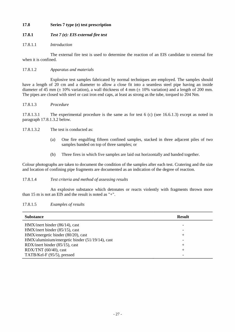
17.8 Series 7 type (e) test prescription 17.8.1 Test 7 (e): EIS external fire test 17.8.1.1 Introduction The external fire test is used to determine the reaction of an EIS candidate to external fire when it is confined. 17.8.1.2 Apparatus and materials Explosive test samples fabricated by normal techniques are employed. The samples should have a length of 20 cm and a diameter to allow a close fit into a seamless steel pipe having an inside diameter of 45 mm (± 10% variation), a wall thickness of 4 mm (± 10% variation) and a length of 200 mm. The pipes are closed with steel or cast iron end caps, at least as strong as the tube, torqued to 204 Nm. 17.8.1.3 Procedure 17.8.1.3.1 The experimental procedure is the same as for test 6 (c) (see 16.6.1.3) except as noted in paragraph 17.8.1.3.2 below. 17.8.1.3.2 The test is conducted as: (a) One fire engulfing fifteen confined samples, stacked in three adjacent piles of two
samples banded on top of three samples; or (b) Three fires in which five samples are laid out horizontally and banded together. Colour photographs are taken to document the condition of the samples after each test. Cratering and the size and location of confining pipe fragments are documented as an indication of the degree of reaction. 17.8.1.4 Test criteria and method of assessing results An explosive substance which detonates or reacts violently with fragments thrown more than 15 m is not an EIS and the result is noted as "+". 17.8.1.5 Examples of results
Substance Result
HMX/inert binder (86/14), cast HMX/inert binder (85/15), cast HMX/energetic binder (80/20), cast HMX/aluminium/energetic binder (51/19/14), cast RDX/inert binder (85/15), cast RDX/TNT (60/40), cast TATB/Kel-F (95/5), pressed
- - + - + + -

- 28 -
17.9 Series 7 type (f) test prescription 17.9.1 Test 7 (f): EIS slow cook-off test 17.9.1.1 Introduction This test is used to determine the reaction of an EIS candidate to a gradually increasing thermal environment and to find the temperature at which reaction occurs. 17.9.1.2 Apparatus and materials 17.9.1.2.1 Explosive test samples fabricated by normal techniques are employed. The samples should have a length of 200 mm and a diameter to allow a close fit into a seamless steel pipe having an inside diameter of 45 mm (± 10% variation), a wall thickness of 4 mm (± 10% variation) and a length of 200 mm. The pipes are closed with steel or cast iron end caps, at least as strong as the tube, torqued to 204 Nm. 17.9.1.2.2 The sample assembly is placed in an oven which provides a controlled thermal environment over a 40 °C to 365 °C temperature range and can increase the temperature of the surrounding oven atmosphere at the rate of 3.3 °C per hour throughout the temperature operating range and ensure, by circulation or other means, a uniform thermal environment to the item under test. 17.9.1.2.3 Temperature recording devices are used to monitor temperature at 10 minute or less intervals; continuous monitoring is preferred. Instrumentation with an accuracy of ± 2% over the test temperature range is used to measure the temperature of: (a) The air within the oven; and (b) The exterior surface of the steel pipe. 17.9.1.3 Procedure 17.9.1.3.1 The test item is subjected to a gradually increasing air temperature at a rate of 3.3 °C per hour until reaction occurs. The test may begin with the test item pre-conditioned to 55 °C below the anticipated reaction temperature. The onset temperature at which the sample temperature exceeds the oven temperature should be recorded. 17.9.1.3.2 After the completion of each test, the pipe or any fragments of pipe are recovered in the test area and examined for evidence of violent explosive reaction. Colour photographs may be taken to document the condition of the unit and the test equipment before and after the test. Cratering, and the size and location of any fragments, may also be documented as indications of the degree of reaction. 17.9.1.3.3 Three tests are conducted for each candidate substance unless a positive result is observed earlier. 17.9.1.4 Test criteria and method of assessing results A substance which detonates or reacts violently (fragmentation of one or two end caps and fragmentation of the tube into more than three pieces) is not considered an EIS and the result is noted as "+".

- 29 -
17.9.1.5 Examples of results
Substance Result
HMX/inert binder (86/14), cast HMX/energetic binder (80/20), cast RDX/TNT (60/40), cast TATB/Kel-F (95/5), pressed
- + + -
17.10 Series 7 type (g) test prescription 17.10.1 Test 7 (g): 1.6 article (or component level) external fire test 17.10.1.1 Introduction The external fire test is used to determine the reaction of a possible Division 1.6 article to external fire as presented for transport. 17.10.1.2 Apparatus and materials The experimental set-up for this test is the same as for test 6 (c) (see 16.6.1.2). 17.10.1.3 Procedure 17.10.1.3.1 The experimental procedure for this test is the same as for test 6 (c) (see 16.6.1.3), except that, if the volume of single item exceeds 0.15 m3, only one item is required. 17.10.1.3.2 Colour still photographs are taken to document the condition of the test item and the test equipment before and after the test. Explosive substance remains, fragmentation, blast, projections, cratering, witness screen damage, and thrust are documented as an indication of the article’s response level.
17.10.1.3.3 Colour video for the duration of each trial can be vital to assessment of response. In sitting the camera(s), it is important to ensure that the field of view will not be obstructed by any of the test facilities or instrumentation and that the field of view will include all necessary information.
17.10.1.3.4 To classify complex articles containing multiple EIS main explosive loads, external fire testing at the individual main load component level should be conducted to fully characterise the article’s response level.
17.10.1.4 Test criteria and method of assessing results If there is a response level more severe than burning as outlined in Appendix 8, the result is noted as "+" and the items are not classified as Division 1.6 articles.
- 30 -
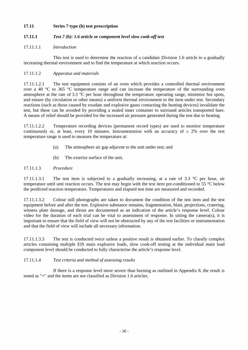
17.11 Series 7 type (h) test prescription 17.11.1 Test 7 (h): 1.6 article or component level slow cook-off test 17.11.1.1 Introduction This test is used to determine the reaction of a candidate Division 1.6 article to a gradually increasing thermal environment and to find the temperature at which reaction occurs. 17.11.1.2 Apparatus and materials 17.11.1.2.1 The test equipment consists of an oven which provides a controlled thermal environment over a 40 °C to 365 °C temperature range and can increase the temperature of the surrounding oven atmosphere at the rate of 3.3 °C per hour throughout the temperature operating range, minimize hot spots, and ensure (by circulation or other means) a uniform thermal environment to the item under test. Secondary reactions (such as those caused by exudate and explosive gases contacting the heating devices) invalidate the test, but these can be avoided by providing a sealed inner container to surround articles transported bare. A means of relief should be provided for the increased air pressure generated during the test due to heating. 17.11.1.2.2 Temperature recording devices (permanent record types) are used to monitor temperature continuously or, at least, every 10 minutes. Instrumentation with an accuracy of ± 2% over the test temperature range is used to measure the temperature at: (a) The atmosphere air gap adjacent to the unit under test; and (b) The exterior surface of the unit. 17.11.1.3 Procedure 17.11.1.3.1 The test item is subjected to a gradually increasing, at a rate of 3.3 °C per hour, air temperature until unit reaction occurs. The test may begin with the test item pre-conditioned to 55 °C below the predicted reaction temperature. Temperatures and elapsed test time are measured and recorded. 17.11.1.3.2 Colour still photographs are taken to document the condition of the test item and the test equipment before and after the test. Explosive substance remains, fragmentation, blast, projections, cratering, witness plate damage, and thrust are documented as an indication of the article’s response level. Colour video for the duration of each trial can be vital to assessment of response. In sitting the camera(s), it is important to ensure that the field of view will not be obstructed by any of the test facilities or instrumentation and that the field of view will include all necessary information.
17.11.1.3.3 The test is conducted twice unless a positive result is obtained earlier. To classify complex articles containing multiple EIS main explosive loads, slow cook-off testing at the individual main load component level should be conducted to fully characterise the article’s response level. 17.11.1.4 Test criteria and method of assessing results If there is a response level more severe than burning as outlined in Appendix 8, the result is noted as "+" and the items are not classified as Division 1.6 articles.
- 31 -
17.12 Series 7 type (j) test prescription 17.12.1 Test 7 (j): 1.6 article or component level bullet impact test 17.12.1.1 Introduction The bullet impact test is used to evaluate the response of a candidate Division 1.6 article to the kinetic energy transfer associated with the impact and penetration by a given energy source. 17.12.1.2 Apparatus and materials Three 12.7 mm guns are used to fire service 12.7 mm armour-piercing ammunition with a projectile mass of 0.046 kg. Standard propellant loads may require adjustment to achieve projectile velocities within tolerance.. The guns are fired by remote control and protected from fragment damage by firing through a hole in a heavy steel plate. The firing gun muzzles should be at a maximum range of at least 10 m from the test item to assure bullet stabilization prior to impact, and at a maximum range of 30 m from the test item depending upon the explosive weight of the test item. The test item should be secured in a holding device capable of restraining the test item against dislodgement by the projectiles. 17.12.1.3 Procedure 17.12.1.3.1 The candidate Division 1.6 article is subjected to a three-round burst fired at 840 ± 40 m/s velocity and 600 rounds/minute rate of fire. The test is repeated in three different orientations, striking the test item in the most vulnerable areas as assessed by the competent authority. These are areas for which an assessment of the explosive sensitivity (explosiveness and sensitiveness) combined with knowledge of the article design indicate the potential producing the most violent response level.
17.12.1.3.2 Colour still photographs are taken to document the condition of the test item and the test equipment before and after the test. Explosive substance remains, fragmentation, blast, projections, cratering, witness plate damage, and thrust are documented as an indication of the article’s response level.
17.12.1.3.3 Colour video for the duration of each trial can be vital to assessment of response. In sitting the camera(s), it is important to ensure that the field of view will not be obstructed by any of the test facilities or instrumentation and that the field of view will include all necessary information.
17.12.1.3.4 To classify complex articles containing multiple EIS main explosive loads, bullet impact testing at the individual main load component level should be conducted to fully characterise the article’s response level. 17.12.1.4 Test criteria and method of assessing results If there is a response level more severe than burning as outlined in Appendix 8, the result is noted as "+" and the items are not classified as Division 1.6 articles.

- 32 -
17.13 Series 7 type (k) test prescription 17.13.1 Test 7 (k): 1.6 article stack test 17.13.1.1 Introduction This test is used to determine whether a detonation of a candidate Division 1.6 article, as offered for transport, will initiate a detonation in an adjacent, like article. 17.13.1.2 Apparatus and materials The experimental set-up is the same as for test 6 (b) (see 16.5.1.2), with one trial conducted confined, and another unconfined. The test should only be conducted on detonable candidate Division 1.6 articles; the test 7 (k) article stack test is waived for non-detonable candidates for Division 1.6 (evidence is available to demonstrate that the article cannot support a detonation). Where the article is designed to provide a detonation output, the article’s own means of initiation or a stimulus of similar power shall be used to initiate the donor. If the article is not designed to detonate but is capable of supporting a detonation, the donor shall be detonated using an initiation system selected to minimise the influence of its explosive effects on the acceptor article(s). 17.13.1.3 Procedure The experimental set-up is the same as for test 6 (b) (see 16.5.1.3). The test is performed twice unless detonation of an acceptor is observed earlier. Colour still photographs are taken to document the condition of the test item and the test equipment before and after the test. Explosive substance remains, fragmentation, blast, projections, cratering, witness plate damage, and thrust are documented and used to assess whether or not any acceptor has detonated (including partially). Blast data may be used to supplement this decision. Colour video for the duration of each trial can be vital to assessment of response. In sitting the camera(s), it is important to ensure that the field of view will not be obstructed by any of the test facilities or instrumentation and that the field of view will include all necessary information. Comparing data from the two stack test trials to data from a single donor calibration shot, or to a calculated donor detonation pressure, can be useful in assessing the response level of acceptors. 17.13.1.4 Test criteria and method of assessing results If detonation in the stack is propagated from the donor to an acceptor, the test result is noted as "+" and the article cannot be assigned to Division 1.6. Acceptor article response levels assessed as no reaction, burning, deflagration, or explosion as outlined in Appendix 8 are considered as negative results and noted as "—".

- 33 -
17.14 Series 7 type (l) test prescription
17.14.1 Test 7 (l): 1.6 article (or component level) fragment impact test
17.14.1.1 Introduction
This test is used to determine the response of an article in its transport configuration to a localised shock input representative of a fragment strike typical of that produced from a nearby detonating article.
17.14.1.2 Apparatus and materials
To reduce variability due to yaw, a gun system is recommended for firing a standard 18.6 g steel fragment in the shape of a right-circular cylinder with a conical nose, as detailed in Figure 17.14.1, at a candidate Division 1.6 article. The distance between the firing device and the test item should ensure that the fragment is ballistically stable at impact. Barricades should protect the remote control gun system from the potential damaging effects of the test item’s reaction.
17.14.1.3 Procedure
17.14.1.3.1 The test is repeated in two different orientations, striking the test item in the most vulnerable areas as assessed by the competent authority. These are areas for which an assessment of the explosive sensitivity (explosiveness and sensitiveness) combined with knowledge of the article design indicate the potential for producing the most violent response level. Typically, one test would be conducted targeting a non-EIS boostering component and the second test would target the centre of the main explosive load. The orientation of impact should generally be normal to the outer surface of the article. The fragment impact velocity should be 2530 ± 90 m/s.
17.14.1.3.2 Colour still photographs are taken to document the condition of the test item and the test equipment before and after the test. Explosive substance remains, fragmentation, blast, projections, cratering, witness plate damage, and thrust are documented as an indication of the article’s response level.
17.14.1.3.3 Colour video for the duration of each trial can be vital to assessment of response. In sitting the camera(s), it is important to ensure that the field of view will not be obstructed by any of the test facilities or instrumentation and that the field of view will include all necessary information.
17.14.1.3.4 To classify complex articles containing multiple EIS main explosive loads, fragment impact testing at the individual main load component level should be conducted to fully characterise the article’s response level.
17.14.1.4 Test criteria and method of assessing results
If there is a response level more severe than burning as outlined in Appendix 8, the result is noted as "+" and the items are not classified as Division 1.6 articles.

- 34 -
15,56 mm14,30 mm
14,
30 m
m
20°
Notes:
Shape: a conical ended cylinder with the ratio L (length)
D (diameter)> 1
for stability;
Tolerances: ± 0.05 mm and ± 0°30'; Fragment mass: 18.6 g; Fragment material: a mild carbon steel with a Brinell Hardness (HB) less than 270.
Figure 17.14.1: STANDARD FRAGMENT FOR 1.6 ARTICLE FRAGMENT IMPACT TEST

- 35 -
Figure 17.14.2: TYPICAL SETUP FOR 1.6 ARTICLE FRAGMENT IMPACT TEST
".
x
Fragment Velocity Measurement
Sabot Stripper Plates
Fragment Projector
Test Item (Restrained if
required)
5m 10m 15m
Blast gauges
Witness Plates
High Speed Camera(s); Impact Point, Article
Response
Real Time Camera (s); Article Response, Explosive Effects
Real Time Camera (s); Article Response, Explosive Effects
Real Time Camera (s); Article Response, Explosive Effects

- 36 -
PART III SECTION 35 Add the following new section :
" SECTION 35
DETERMINATION OF CHEMICAL INSTABILITY OF GASES AND GAS MIXTURES
35.0 Introduction
This section presents the United Nations scheme for the classification of gases and gas mixtures as chemically unstable. The text should be used in conjunction with the classification principles given in Chapter 2.2 of the Globally Harmonized System of Classification and Labelling of Chemicals (GHS) and the test methods given in this section.
35.1 Purpose
35.1.1 This test method is used to determine the chemical instability of a gas or gas mixture by ignition tests in a closed vessel at ambient and elevated temperature and pressure.
35.1.2 For the purposes of this test method the following definitions apply:
Chemical instability means the propensity of a gas or gas mixture to react dangerously even in the absence of any reaction partner (e.g. air or oxygen) by decomposing and thereby causing a temperature and/or pressure increase;
Test gas means the gas or gas mixture to be evaluated by this test method;
Corresponding initial pressure means the pressure at which the test at 65 °C is carried out. For test gases that are completely gaseous the corresponding initial pressure is the pressure that a gas develops at 65 °C based on the maximum (filling) pressure at ambient temperature. For liquefied test gases the corresponding initial pressure is the vapour pressure at 65 °C.
35.2 Scope
35.2.1 The test method does not cover gas decomposition under process conditions in chemical plants and possible dangerous reactions between different gases in gas mixtures.
35.2.2 Mixtures of gases, where the components can react dangerously with each other, e.g. flammable and oxidizing gases, are not regarded as chemically unstable in the sense of this test method.
35.2.3 If the calculations in accordance with ISO 10156:2010 show that a gas mixture is not flammable it is not necessary to carry out the tests for determining chemical instability for classification purposes.
35.2.4 Expert judgement should be applied to decide whether a flammable gas or gas mixture is a candidate for classification as chemically unstable in order to avoid unnecessary testing of gases where there is no doubt that they are stable. Functional groups indicating chemical instability in gases are triple-bonds, adjacent or conjugated double-bonds, halogenated double-bonds and strained rings.

- 37 -
35.3 Concentration limits
35.3.1 Generic concentration limits
35.3.1.1 Gas mixtures containing only one chemically unstable gas are not considered as chemically unstable and therefore do not have to be tested for classification purposes if the concentration of the chemically unstable gas is below the higher of the following generic concentration limits:
(a) The lower explosion limit (LEL) of the chemically unstable gas; or
(b) 3 mole%.
35.3.2 Specific concentration limits
35.3.2.1 The following tables contain information about some gases with regard to their classification as chemically unstable. Specific concentration limits for their mixtures are given. Gas mixtures containing only one chemically unstable gas in concentrations below the specific concentration limit are not considered as chemically unstable and therefore do not have to be tested for classification purposes.
Table 35.1: Information about gases with regard to their chemical instability and concentration limits for their mixtures below which the mixtures are not classified as chemically unstable
Information about the pure gas Information about its mixtures
Chemical Name
Molecular formula
CAS No. UN No. Classification Specific concentration limit (see Notes 1 and 2)
Acetylene C2H2 74-86-2 1001 3374
Chem. Unst. Cat. A See Table 35.2 For other mixtures: Partial pressure of 1 bar abs
Bromotrifluoro-ethylene
C2BrF3 598-73-2 2419 Chem. Unst. Cat. B 8.4 mole% (LEL)
Butadiene-1,2 C4H6 590-19-2 1010 Not classified as chemically unstable
Butadiene-1,3 C4H6 106-99-0 1010 Not classified as chemically unstable
Butyne–1, Ethylacetylene
C4H6 107-00-6 2452 Chem. Unst. Cat. B The specific concentration limits for acetylene may be applied, see Table 35.2. For other mixtures: Partial pressure of 1 bar abs
Chlorotrifluoro-ethylene
C2ClF3 79-38-9 1082 Chem. Unst. Cat. B 4.6 mole% (LEL)
Ethylene oxide C2H4O 75-21-8 1040 Chem. Unst. Cat. A 15 mole% for mixtures containing rare gases. 30 mole% for other mixtures
Vinyl methyl ether
C3H6O 107-25-5 1087 Chem. Unst. Cat. B 3 mole%
Propadiene C3H4 463-49-0 2200 Chem. Unst. Cat. B The specific concentration limits for acetylene may be applied, see Table 35.2. For other mixtures: Partial pressure of 1 bar abs
Propyne C3H4 74-99-7 3161 Chem. Unst. Cat. B The specific concentration limits for acetylene may be applied, see Table 35.2. For other mixtures:

- 38 -
Information about the pure gas Information about its mixtures
Chemical Name
Molecular formula
CAS No. UN No. Classification Specific concentration limit (see Notes 1 and 2)
Partial pressure of 1 bar abs Tetrafluoro-ethylene
C2F4 116-14-3 1081 Chem. Unst. Cat. B 10.5 mole% (LEL)
Trifluoro-ethylene
C2HF3 359-11-5 1954 Chem. Unst. Cat. B 10.5 mole% (LEL)
Vinyl bromide C2H3Br 593-60-2 1085 Chem. Unst. Cat. B 5.6 mole% (LEL) Vinyl chloride C2H3Cl 75-01-4 1086 Chem. Unst. Cat. B 3.8 mole% (LEL) Vinyl fluoride C2H3F 75-02-5 1860 Chem. Unst. Cat. B 3 mole%
NOTE 1: The maximum pressure should be limited in order to avoid condensation.
NOTE 2: The test method is not applicable to liquefied gas mixtures. In case the gaseous phase above a liquefied gas mixture may become chemically unstable after withdrawal, this shall be communicated via the safety data sheet.
Table 35.2: Specific concentration limits for binary mixtures with acetylene. These concentration limits may also be applied to butyne-1 (ethylacetylene), propadiene and propyne
Maximum (filling) pressure in bar for a mixture with Concentration limit for acetylene
in mol % N2 CO2 NH3 H2 CH4 C3H8 C2H4
3.0 200.0 200.0
4.0 100.0
5.0 40.0 40.0
6.0 80.0
8.0 60.0
10.0 50.0 38.0 5.6 20.0 100.0 6.0 20.0
15.0 30.0 30.0 10.0 10.0
20.0 25.0 20.0 6.2 5.0 50.0 6.6 7.5
25.0 20.0 15.0 5.0
30.0 10.0 10.0 6.9 25.0 7.3
35.0 7.3
40.0 15.0 8.2
45.0
50.0 5.0 9.3
60.0 10.8

- 39 -
35.4 Test method
35.4.1 Introduction
35.4.1.1 The propensity of a gas to decompose depends strongly on pressure, temperature and in case of gas mixtures on the concentration of the chemically unstable component. The possibility of decomposition reactions shall be evaluated at conditions which are relevant for handling and use and transport. Therefore two types of tests shall be performed:
(a) At ambient temperature and pressure,
(b) At 65 °C and the corresponding initial pressure.
35.4.2 Apparatus and material
35.4.2.1 The test apparatus (see Figure 35.1) consist of a pressure resistant test vessel (heatable) made of stainless steel; an ignition source; a measuring and recording system to record the pressure inside the ignition vessel; a gas supply; a venting system with bursting disc and additional piping, fitted with remote-controlled valves and cocks.
(a) Pressure resistant test vessel
The test vessel is a cylindrical stainless steel vessel with an inner volume of about 1 dm3 and an inner diameter of 80 mm. An exploding wire ignition source is screwed into the bottom of the vessel. The vessel is equipped with a heating jacket which is connected to a temperature control unit that heats the outer vessel wall with an accuracy of ± 2 K. The test vessel is insulated with temperature resistant insulation material to avoid heat loss and temperature gradients. The test vessel shall be pressure resistant up to 500 bar (50 MPa).
(b) Exploding wire igniter
The ignition source is an exploding (fusing) wire igniter similar to that described in ASTM E 918 and EN 1839. The igniter consists of two insulated electrodes at 3 mm to 6 mm distance, holding a nickeline wire of 0.12 mm diameter at its ends. The ignition energy is provided by a 1.5 kVA/230 (115) V insulating transformer, which is switched for a short time period to this igniter. The wire melts and then an electrical arc burns between the electrodes for a period extending in maximum to half a period of the supply voltage (10 (8.3) ms). An electronic control unit allows switching different time periods of the mains voltage half wave to the igniter. The corresponding energy delivered shall be in the range of 15 J ± 3 J. The energy can be measured by recording the current and voltage during ignition.
(c) Pressure and temperature recording equipment
The pressure inside the ignition vessel shall be measured with a calibrated piezoresistive pressure transducer. The measuring range shall be 20 times higher than the initial pressure. The sensitivity shall be at least 0.1% of the full scale and the accuracy shall be better than 0.5% of the full scale.
The temperature of the ignition vessel shall be measured and controlled with a 3 mm thermocouple type “K” (NiCr/NiAl) mounted 50 mm below the top inside the autoclave.
After ignition the digitized pressure signal shall be recorded with a computer. The initial pressure (p0) and the highest pressure (pex) are derived from the raw data.

- 40 -
(d) Gas supply
Two different types of gas supply are necessary, one for test gases that are completely in the gaseous phase and one for liquefied test gases. Test gases in the gaseous phase are metered volumetric or by flow measurement and liquefied test gases are metered gravimetric.
(e) Bursting disc
The bursting disc is supposed to protect the test vessel. It is connected to a vent pipe for the exhaust gas. The free diameter of the bursting disc should be at least 10 mm, the inner diameter of the pipe at least 15 mm. The opening pressure of the bursting disc shall amount to 250 bar (25 MPa).
(f) Additional piping and valves
The piping and valves which are fitted directly to the test vessel, shall be pressure resistant up to 500 bar (50 MPa). The test apparatus shall be operated by remotely operated valves.
35.4.3 Test procedure
35.4.3.1 The test gas is charged into a pressure resistant stainless steel vessel at controlled temperature and pressure. The vessel is equipped with a bursting disc. Ignition of the test gas is achieved with an exploding wire igniter. Whether a decomposition reaction has occurred is deduced from the pressure rise produced.
35.4.3.2 The tests shall be executed in the following sequence:
(a) Test at ambient temperature and pressure
For the tests at 20 °C and 1.01 bar (101.3 kPa) the exploding wire igniter shall be arranged in the middle of the test vessel. The test vessel and the piping are evacuated. The test gas is filled into the test vessel by using the remotely operated valves until ambient pressure (initial pressure) is reached. After closing the valves the igniter is fired. The ignition energy shall be about 15 J to avoid over-initiation in the test vessel at this relatively low pressure. Criterion for a reaction is a pressure rise of more than 20% after ignition (f = pex/p0 > 1.20). If no such pressure rise has occurred two further re-tests shall be carried out.
If the test gas shows a pressure rise of more than 20% in either of the tests it is to be classified as "chemically unstable at 20 °C and a standard pressure of 101.3 kPa". No further tests are required.
(b) Test at elevated temperature and pressure
If in the tests according to 35.4.3.2 (a) no pressure rise of more than 20% has occurred, further tests at 65 °C and the corresponding initial pressure shall be performed. The procedure is the same as in 35.3.3.2 (a) but care should be taken with potentially unstable gases under pressure. The ignition energy shall be about 15 J. If no pressure rise of more than 20% has occurred two further re-tests shall be carried out.
If the test gas shows a pressure rise of more than 20% in either of the tests it is to be classified as "chemically unstable at a temperature greater than 20 °C and/or a pressure greater than 101.3 kPa".

- 41 -
35.4.4 Safety precautions
35.4.4.1 Adequate shielding of the test apparatus must be provided to prevent injury in the event of equipment rupture. The apparatus is to be set up in such a way that the operator does not have to be in the same room as long as the vessel contains test gas. Alternatively, the test apparatus is separated by a blast proof barrier from the operator. Activation of the ignition source should be possible only from a position shielded from the test vessel.
35.4.4.2 The test vessel shall be fitted with a bursting disc connected to a vent pipe that allows venting the exhaust gas safely. Therefore it has to be taken into account that the exhaust gas can be hazardous itself (e.g. flammable or toxic).
35.4.4.3 The gas cylinder containing the test gas shall be equipped with a non-return valve and shall be separated from the test apparatus before the igniter is fired to avoid backfiring into the cylinder. The cylinder valve has to be closed immediately after finishing the filling.
35.4.4.4 Some chemically unstable gases can explode very violently especially at higher pressures. Therefore it is strongly recommended to start with the experiments at atmospheric pressure.
35.4.5 Test criteria and method of assessing results
35.4.5.1 Chemically unstable gases or gas mixtures shall be classified as “chemically unstable at 20 °C and a standard pressure of 101.3 kPa” or “chemically unstable at a temperature greater than 20 °C and/or a pressure greater than 101.3 kPa” according to the test results as follows:
(a) The gas is classified as “chemically unstable at 20 °C and a standard pressure of 101.3 kPa” if the test at 20 °C and 1.01 bar (101.3 kPa) shows a pressure rise of more than 20% of the initial absolute pressure.
(b) The gas is classified as “chemically unstable at a temperature greater than 20 °C and/or a pressure greater than 101.3 kPa” if the test at 65 °C and the corresponding initial pressure shows a pressure rise of more than 20% of the initial absolute pressure but no such pressure rise at 20 °C and 1.01 bar (101.3 kPa).
35.4.5.2 The gas is not classified according to this test method (i.e: it is chemically stable) if it does not show a pressure rise of more than 20% of the initial absolute pressure in either of the tests.
NOTE: Chemically unstable gases not submitted to the classification procedure in this section should be classified as chemically unstable, Category A (see Chapter 2.2 of the GHS).

- 42 -
waste gas
ER
2
5
7
9
pressurized Helium
Te
st s
ubst
an
ce
3
1
waste gas
10
Tes
t su
bsta
nce
PIR
TIC
M
M
4
6
8
11
A B
CDE
F
G
H
I
J
K
L
L
N
PQ
P
(A) Test gas supply (gaseous) (B) Test gas supply (liquefied)
(C) Pressure resistant test vessel (D) Regulated electric heater
(E) Thermal insulation (F) Exploding wire igniter
(G) Pressure sensor, pressure indication and registration (PIR)
(H) Bursting disc
(I) Electronic ignition device (J) Energy registration (ER)
(K) Vacuum pump (L) Exhaust gas
(M) Motor controlled valve (N) Pressurized helium
(P) Test gas (Q) Temperature sensor, temperature indication and control (TIC)
Figure 35.1: TEST APPARATUS
".

- 43 -
SECTION 38 38.3 Amend to read as follows:
"38.3 Lithium metal and lithium ion batteries 38.3.1 Purpose This section presents the procedures to be followed for the classification of lithium metal and lithium ion cells and batteries (see UN Nos. 3090, 3091, 3480 and 3481, and the applicable special provisions of Chapter 3.3 of the Model Regulations). 38.3.2 Scope 38.3.2.1 All cell types shall be subjected to tests T.1 to T.6 and T.8. All non-rechargeable battery types, including those composed of previously tested cells, shall be subjected to tests T.1 to T.5. All rechargeable battery types, including those composed of previously tested cells, shall be subjected to tests T.1 to T.5 and T.7. In addition, rechargeable single cell batteries with overcharge protection shall be subjected to test T.7. A component cell that is not transported separately from the battery it is part of needs only to be tested according to tests T.6 and T.8. A component cell that is transported separately from the battery shall be tested as a cell. 38.3.2.2 Lithium metal and lithium ion cells and batteries shall be subjected to the tests, as required by special provisions 188 and 230 of Chapter 3.3 of the Model Regulations prior to the transport of a particular cell or battery type. Cells or batteries which differ from a tested type by:
(a) For primary cells and batteries, a change of more than 0.1 g or 20% by mass, whichever is greater, to the cathode, to the anode, or to the electrolyte;
(b) For rechargeable cells and batteries, a change in nominal energy in Watt-hours of
more than 20% or an increase in nominal voltage of more than 20%; or (c) A change that would lead to failure of any of the tests,
shall be considered a new type and shall be subjected to the required tests. NOTE: The type of change that might be considered to differ from a tested type, such that it might lead to failure of any of the test results, may include, but is not limited to: (a) A change in the material of the anode, the cathode, the separator or the electrolyte; (b) A change of protective devices, including hardware and software; (c) A change of safety design in cells or batteries, such as a venting valve; (d) A change in the number of component cells; and (e) A change in connecting mode of component cells. In the event that a cell or battery type does not meet one or more of the test requirements, steps shall be taken to correct the deficiency or deficiencies that caused the failure before such cell or battery type is retested. 38.3.2.3 For the purposes of classification, the following definitions apply: Aggregate lithium content means the sum of the grams of lithium content contained by the cells comprising a battery.
- 44 -
Battery means two or more cells which are electrically connected together and fitted with devices necessary for use, for example, case, terminals, marking and protective devices. A single cell battery is considered a "cell" and shall be tested according to the testing requirements for "cells" for the purposes of the Model Regulations and this Manual (see also the definition for "cell").
NOTE: Units that are commonly referred to as "battery packs", "modules" or "battery assemblies" having the primary function of providing a source of power to another piece of equipment are for the purposes of the Model Regulations and this Manual treated as batteries. Button cell or battery means a round small cell or battery when the overall height is less than the diameter. Cell means a single encased electrochemical unit (one positive and one negative electrode) which exhibits a voltage differential across its two terminals. Under the Model Regulations and this Manual, to the extent the encased electrochemical unit meets the definition of "cell" herein, it is a "cell", not a "battery", regardless of whether the unit is termed a "battery" or a "single cell battery" outside of the Model Regulations and this Manual. Component cell means a cell contained in a battery. Cycle means one sequence of fully charging and fully discharging a rechargeable cell or battery. Disassembly means a vent or rupture where solid matter from any part of a cell or battery penetrates a wire mesh screen (annealed aluminium wire with a diameter of 0.25 mm and grid density of 6 to 7 wires per cm) placed 25 cm away from the cell or battery. Effluent means a liquid or gas released when a cell or battery vents or leaks. Fire means that flames are emitted from the test cell or battery. First cycle means the initial cycle following completion of all manufacturing processes. Fully charged means a rechargeable cell or battery which has been electrically charged to its design rated capacity. Fully discharged means either:
a primary cell or battery which has been electrically discharged to remove 100% of its rated capacity; or a rechargeable cell or battery which has been electrically discharged to its endpoint voltage as specified by the manufacturer.
Large battery means a lithium metal battery or lithium ion battery with a gross mass of more than 12 kg. Large cell means a cell with a gross mass of more than 500 g. Leakage means the visible escape of electrolyte or other material from a cell or battery or the loss of material (except battery casing, handling devices or labels) from a cell or battery such that the loss of mass exceeds the values in Table 38.3.1. Lithium content is applied to lithium metal and lithium alloy cells and batteries, and for a cell means the mass of lithium in the anode of a lithium metal or lithium alloy cell, which for a primary cell is measured when the cell is in an undischarged state and for a rechargeable cell is measured when the cell is fully charged. The lithium content of a battery equals the sum of the grams of lithium content contained in the component cells of the battery.

- 45 -
Lithium ion cell or battery means a rechargeable electrochemical cell or battery in which the positive and negative electrodes are both intercalation compounds (intercalated lithium exists in an ionic or quasi-atomic form with the lattice of the electrode material) constructed with no metallic lithium in either electrode. A lithium polymer cell or battery that uses lithium ion chemistries, as described herein, is regulated as a lithium ion cell or battery. Mass loss means a loss of mass that exceeds the values in Table 38.3.1 below.
Table 38.3.1: Mass loss limit
Mass M of cell or battery Mass loss limit M < 1 g 0.5%
l g ≤ M ≤ 75 g 0.2% M > 75 g 0.1%
NOTE: In order to quantify the mass loss, the following procedure is provided:
(M1 — M2) Mass loss (%) = M1
x 100
where M1 is the mass before the test and M2 is the mass after the test. When mass loss does not exceed the values in Table 38.3.1, it shall be considered as "no mass loss". Nominal energy or Watt-hour rating, expressed in watt-hours, means the energy value of a cell or battery determined under specified conditions and declared by the manufacturer. The nominal energy is calculated by multiplying nominal voltage by rated capacity expressed in ampere-hours. Nominal voltage means the approximate value of the voltage used to designate or identify a cell or battery. Open circuit voltage means the voltage across the terminals of a cell or battery when no external current is flowing. Primary cell or battery means a cell or battery which is not designed to be electrically charged or recharged. Prismatic cell or battery means a cell or battery whose ends are similar, equal and parallel rectilinear figures, and whose sides are parallelograms. Protective devices means devices such as fuses, diodes and current limiters which interrupt the current flow, block the current flow in one direction or limit the current flow in an electrical circuit. Rated capacity means the capacity, in ampere-hours or milliampere-hours, of a cell or battery as measured by subjecting it to a load, temperature and voltage cut-off point specified by the manufacturer. NOTE: The following IEC standards provide guidance and methodology for determining the rated capacity: (1) IEC 61960 (First Edition 2003-12) : Secondary cells and batteries containing alkaline or other non-acid electrolytes – Secondary lithium cells and batteries for portable applications; (2) IEC 62133 (First Edition 2002-10): Secondary cells and batteries containing alkaline or other non-acid electrolytes – Safety requirements for portable sealed secondary cells, and for batteries made from them, for use in portable applications; (3) IEC 62660-1 (First Edition 2011-01): Secondary lithium-ion cells for the propulsion of electric road vehicles – Part 1: Performance testing. Rechargeable cell or battery means a cell or battery which is designed to be electrically recharged.

- 46 -
Rupture means the mechanical failure of a cell container or battery case induced by an internal or external cause, resulting in exposure or spillage but not ejection of solid materials. Short circuit means a direct connection between positive and negative terminals of a cell or battery that provides a virtual zero resistance path for current flow. Single cell battery means a single electrochemical unit fitted with devices necessary for use, for example, case, terminals, marking and protective devices. Small battery means a lithium metal battery or lithium ion battery with a gross mass of not more than 12 kg. Small cell means a cell with a gross mass of not more than 500 g. Type means a particular electrochemical system and physical design of cells or batteries. Undischarged means a primary cell or battery that has not been wholly or partly discharged. Venting means the release of excessive internal pressure from a cell or battery in a manner intended by design to preclude rupture or disassembly. Watt-hour rating, see Nominal energy. 38.3.3 When a cell or battery type is to be tested under this sub-section, the number and condition of cells and batteries of each type to be tested are as follows:
(a) When testing primary cells and batteries under tests T.1 to T.5 the following shall be
tested in the quantity indicated:
(i) ten cells in undischarged states;
(ii) ten cells in fully discharged states;
(iii) four small batteries in undischarged states;
(iv) four small batteries in fully discharged states;
(v) four large batteries in undischarged states; and
(vi) four large batteries in fully discharged states.
(b) When testing rechargeable cells and batteries under tests T.1 to T.5 the following shall be tested in the quantity indicated:
(i) ten cells at first cycle, in fully charged states;
(ii) four small batteries at first cycle, in fully charged states;
(iii) four small batteries after 50 cycles ending in fully charged states;
(iv) two large batteries at first cycle, in fully charged states; and
(v) two large batteries after 25 cycles ending in fully charged states.
(c) When testing primary and rechargeable cells under test T.6, the following shall be tested in the quantity indicated:
(i) for primary cells, five cells in undischarged states and five cells in fully
discharged states;
(ii) for component cells of primary batteries, five cells in undischarged states and five cells in fully discharged states;

- 47 -
(iii) for rechargeable cells, five cells at first cycle at 50% of the design rated capacity; and
(iv) for component cells of rechargeable batteries, five cells at first cycle at 50% of the design rated capacity.
(d) When testing rechargeable batteries or rechargeable single cell batteries under test T.7,
the following shall be tested in the quantity indicated:
(i) four small batteries at first cycle, in fully charged states;
(ii) four small batteries after 50 cycles ending in fully charged states;
(iii) two large batteries at first cycle, in fully charged states; and
(iv) two large batteries after 25 cycles ending in fully charged states. Batteries not equipped with overcharge protection that are designed for use only in a battery assembly, which affords such protection, are not subject to the requirements of this test.
(e) When testing primary and rechargeable cells and component cells under test T.8, the
following shall be tested in the quantity indicated:
(i) ten primary cells in fully discharged states;
(ii) ten primary component cells in fully discharged states;
(iii) ten rechargeable cells, at first cycle in fully discharged states;
(iv) ten rechargeable component cells, at first cycle in fully discharged states;
(v) ten rechargeable cells after 50 cycles ending in fully discharged states; and
(vi) ten rechargeable component cells after 50 cycles ending in fully discharged states.
(f) When testing a battery assembly in which the aggregate lithium content of all anodes,
when fully charged, is not more than 500 g, or in the case of a lithium ion battery, with a Watt-hour rating of not more than 6 200 Watt-hours, that is assembled from batteries that have passed all applicable tests, one battery assembly in a fully charged state shall be tested under tests T.3, T.4 and T.5, and, in addition, test T.7 in the case of a rechargeable battery assembly. For a rechargeable battery assembly, the assembly shall have been cycled at least 25 cycles.
When batteries that have passed all applicable tests are electrically connected to form a battery assembly in which the aggregate lithium content of all anodes, when fully charged, is more than 500 g, or in the case of a lithium ion battery, with a Watt-hour rating of more than 6 200 Watt-hours, that battery assembly does not need to be tested if it is equipped with a system capable of monitoring the battery assembly and preventing short circuits, or over discharge between the batteries in the assembly and any overheat or overcharge of the battery assembly.
38.3.4 Procedure Tests T.1 to T.5 shall be conducted in sequence on the same cell or battery. Tests T.6 and T.8 shall be conducted using not otherwise tested cells or batteries. Test T.7 may be conducted using undamaged batteries previously used in tests T.1 to T.5 for purposes of testing on cycled batteries.
- 48 -
38.3.4.1 Test T.1: Altitude simulation 38.3.4.1.1 Purpose This test simulates air transport under low-pressure conditions. 38.3.4.1.2 Test procedure Test cells and batteries shall be stored at a pressure of 11.6 kPa or less for at least six hours at ambient temperature (20 ± 5 °C). 38.3.4.1.3 Requirement Cells and batteries meet this requirement if there is no leakage, no venting, no disassembly, no rupture and no fire and if the open circuit voltage of each test cell or battery after testing is not less than 90% of its voltage immediately prior to this procedure. The requirement relating to voltage is not applicable to test cells and batteries at fully discharged states. 38.3.4.2 Test T.2: Thermal test 38.3.4.2.1 Purpose This test assesses cell and battery seal integrity and internal electrical connections. The test is conducted using rapid and extreme temperature changes. 38.3.4.2.2 Test procedure Test cells and batteries are to be stored for at least six hours at a test temperature equal to72 ± 2 °C, followed by storage for at least six hours at a test temperature equal to - 40 ± 2 °C. The maximum time interval between test temperature extremes is 30 minutes. This procedure is to be repeated until 10 total cycles are complete, after which all test cells and batteries are to be stored for 24 hours at ambient temperature (20 ± 5 °C). For large cells and batteries the duration of exposure to the test temperature extremes should be at least 12 hours. 38.3.4.2.3 Requirement Cells and batteries meet this requirement if there is no leakage, no venting, no disassembly, no rupture and no fire and if the open circuit voltage of each test cell or battery after testing is not less than 90% of its voltage immediately prior to this procedure. The requirement relating to voltage is not applicable to test cells and batteries at fully discharged states. 38.3.4.3 Test T.3: Vibration
38.3.4.3.1 Purpose This test simulates vibration during transport. 38.3.4.3.2 Test procedure
Cells and batteries are firmly secured to the platform of the vibration machine without distorting the cells in such a manner as to faithfully transmit the vibration. The vibration shall be a sinusoidal waveform with a logarithmic sweep between 7 Hz and 200 Hz and back to 7 Hz traversed in 15 minutes. This cycle shall be repeated 12 times for a total of 3 hours for each of three mutually perpendicular mounting positions of the cell. One of the directions of vibration must be perpendicular to the terminal face. The logarithmic frequency sweep shall differ for cells and batteries with a gross mass of not more than 12 kg (cells and small batteries), and for batteries with a gross mass of more than 12 kg (large batteries).

- 49 -
For cells and small batteries: from 7 Hz a peak acceleration of 1 gn is maintained until 18 Hz is reached. The amplitude is then maintained at 0.8 mm (1 6 mm total excursion) and the frequency increased until a peak acceleration of 8 gn occurs (approximately 50 Hz). A peak acceleration of 8 gn is then maintained until the frequency is increased to 200 Hz. For large batteries: from 7 Hz to a peak acceleration of 1 gn is maintained until 18 Hz is reached. The amplitude is then maintained at 0.8 mm (1.6 mm total excursion) and the frequency increased until a peak acceleration of 2 gn occurs (approximately 25 Hz). A peak acceleration of 2 gn is then maintained until the frequency is increased to 200 Hz. 38.3.4.3.3 Requirement
Cells and batteries meet this requirement if there is no leakage, no venting, no disassembly, no rupture and no fire during the test and after the test and if the open circuit voltage of each test cell or battery directly after testing in its third perpendicular mounting position is not less than 90% of its voltage immediately prior to this procedure. The requirement relating to voltage is not applicable to test cells and batteries at fully discharged states. 38.3.4.4 Test T.4: Shock
38.3.4.4.1 Purpose
This test simulates possible impacts during transport. 38.3.4.4.2 Test procedure Test cells and batteries shall be secured to the testing machine by means of a rigid mount which will support all mounting surfaces of each test battery. Each cell or battery shall be subjected to a half-sine shock of peak acceleration of 150 gn and pulse duration of 6 milliseconds. Each cell or battery shall be subjected to three shocks in the positive direction followed by three shocks in the negative direction of three mutually perpendicular mounting positions of the cell or battery for a total of 18 shocks. However, large cells and large batteries shall be subjected to a half-sine shock of peak acceleration of 50 gn and pulse duration of 11 milliseconds. Each cell or battery is subjected to three shocks in the positive direction followed by three shocks in the negative direction of each of three mutually perpendicular mounting positions of the cell for a total of 18 shocks. 38.3.4.4.3 Requirement
Cells and batteries meet this requirement if there is no leakage, no venting, no disassembly, no rupture and no fire and if the open circuit voltage of each test cell or battery after testing is not less than 90% of its voltage immediately prior to this procedure. The requirement relating to voltage is not applicable to test cells and batteries at fully discharged states.
38.3.4.5 Test T.5: External short circuit 38.3.4.5.1 Purpose
This test simulates an external short circuit.

- 50 -
38.3.4.5.2 Test procedure
The cell or battery to be tested shall be temperature stabilized so that its external case temperature reaches 55 ± 2 °C and then the cell or battery shall be subjected to a short circuit condition with a total external resistance of less than 0.1 ohm at 55 ± 2 °C. This short circuit condition is continued for at least one hour after the cell or battery external case temperature has returned to 55 ± 2 °C. 38.3.4.5.3 Requirement
Cells and batteries meet this requirement if their external temperature does not exceed 170 °C and there is no disassembly, no rupture and no fire during the test and within six hours after the test. 38.3.4.6 Test T.6: Impact / Crush 38.3.4.6.1 Purpose
These tests simulate mechanical abuse from an impact or crush that may result in an internal short circuit. 38.3.4.6.2 Test procedure – Impact (applicable to cylindrical cells greater than 20 mm in diameter)
The sample cell or component cell is to be placed on a flat smooth surface. A 15.8 mm ± 0.1mm diameter, at least 6 cm long, or the longest dimension of the cell, whichever is greater, Type 316 stainless steel bar is to be placed across the centre of the sample. A 9.1 kg ± 0.1 kg mass is to be dropped from a height of 61 ± 2.5 cm at the intersection of the bar and sample in a controlled manner using a near frictionless, vertical sliding track or channel with minimal drag on the falling mass. The vertical track or channel used to guide the falling mass shall be oriented 90 degrees from the horizontal supporting surface. The test sample is to be impacted with its longitudinal axis parallel to the flat surface and perpendicular to the longitudinal axis of the 15.8 mm ± 0.1mm diameter curved surface lying across the centre of the test sample. Each sample is to be subjected to only a single impact. 38.3.4.6.3 Test Procedure – Crush (applicable to prismatic, pouch, coin/button cells and cylindrical cells not more than 20 mm in diameter)
A cell or component cell is to be crushed between two flat surfaces. The crushing is to be gradual with a speed of approximately 1.5 cm/s at the first point of contact. The crushing is to be continued until the first of the three options below is reached. (a) The applied force reaches 13 kN ± 0.78 kN; Example: The force shall be applied by a hydraulic ram with a 32 mm diameter piston
until a pressure of 17 MPa is reached on the hydraulic ram. (b) The voltage of the cell drops by at least 100 mV; or (c) The cell is deformed by 50% or more of its original thickness. Once the maximum pressure has been obtained, the voltage drops by 100 mV or more, or the cell is deformed by at least 50% of its original thickness, the pressure shall be released. A prismatic or pouch cell shall be crushed by applying the force to the widest side. A button/coin cell shall be crushed by applying the force on its flat surfaces. For cylindrical cells, the crush force shall be applied perpendicular to the longitudinal axis.
- 51 -
Each test cell or component cell is to be subjected to one crush only. The test sample shall be observed for a further 6 h. The test shall be conducted using test cells or component cells that have not previously been subjected to other tests. 38.3.4 6.4 Requirement
Cells and component cells meet this requirement if their external temperature does not exceed 170 °C and there is no disassembly and no fire during the test and within six hours after this test. 38.3.4.7 Test T.7: Overcharge
38.3.4.7.1 Purpose
This test evaluates the ability of a rechargeable battery to withstand an overcharge condition.
38.3.4.7.2 Test procedure The charge current shall be twice the manufacturer's recommended maximum continuous charge current. The minimum voltage of the test shall be as follows: (a) when the manufacturer's recommended charge voltage is not more than 18V, the
minimum voltage of the test shall be the lesser of two times the maximum charge voltage of the battery or 22V.
(b) when the manufacturer's recommended charge voltage is more than 18V, the
minimum voltage of the test shall be 1.2 times the maximum charge voltage. Tests are to be conducted at ambient temperature. The duration of the test shall be 24 hours. 38.3.4.7.3 Requirement
Rechargeable batteries meet this requirement if there is no disassembly and no fire during the test and within seven days after the test.
38.3.4.8 Test T.8: Forced discharge
38.3.4.8.1 Purpose
This test evaluates the ability of a primary or a rechargeable cell to withstand a forced discharge condition. 38.3.4.8.2 Test procedure
Each cell shall be forced discharged at ambient temperature by connecting it in series with a 12V D.C. power supply at an initial current equal to the maximum discharge current specified by the manufacturer. The specified discharge current is to be obtained by connecting a resistive load of the appropriate size and rating in series with the test cell. Each cell shall be forced discharged for a time interval (in hours) equal to its rated capacity divided by the initial test current (in ampere). 38.3.4.8.3 Requirement
Primary or rechargeable cells meet this requirement if there is no disassembly and no fire during the test and within seven days after the test. ".

- 52 -
PART IV SECTION 41 41.2.2 Amend to read as follows:
"41.2.2 MEGCs
(a) A decrease in the maximum design temperature, not affecting thickness;
(b) An increase in the minimum design temperature, not affecting thickness;
(c) A decrease in the maximum permissible gross mass;
(d) A decrease in the mass of each individual element and its lading or a decrease in the total mass of the elements and their lading;
(e) An increase of no more than 10% or a decrease of no more than 40% in the diameter of the elements;
(f) A change of no more than 10% in the length of the elements;
(g) A decrease of no more than 3.1 metres (10 feet) in the length of the MEGC framework;
(h) A decrease of no more than 50% in the height of the MEGC;
(i) A change of no more than 50% in the number of elements;
(j) An increase in the thickness of the materials of the framework provided the thickness stays within the range permitted by the welding procedure specifications;
(k) A change to the service equipment and manifold such that the total mass of the service equipment and manifold changes no more than 10% of the maximum permissible gross mass (but not resulting in an increase in the maximum permissible gross mass as compared to that of the already-tested prototype);
(l) The use of a different grade of the same type of material for the construction of the framework, provided that:
(i) The results of the design calculations for the different grade, using the most unfavourable specified values of mechanical properties for that grade, meet or exceed the results of the design calculation for the existing grade; and
(ii) The alternate grade is permitted by the welding procedure specifications.
NOTE: For permitted MEGC design variations not requiring additional impact testing, the mounting apparatus attaching the elements to the framework must remain the same as that for the already-tested prototype MEGC design. ".

- 53 -
APPENDICES
Add a new Appendix 8 to read as follows:
"APPENDIX 8
RESPONSE DESCRIPTORS
These response descriptors are to be used for the purposes of Test Series 7 criteria and designed to be used by the competent authority to determine the response type of articles. For example, articles vary greatly in size, type, packaging and explosive substances; these differences need to be taken into account. For a reaction to be judged a particular type, the primary evidence (denoted P in the table below) for that type would need to be present. The entire (both primary and secondary) body of evidence must be weighed carefully and used in its entirety by the competent authority to assess the reaction. The secondary evidence provides other indicators that may be present.

-54-
Observed or measured effects Response
level Explosive
Substances (ES) Case Blast Fragment or ES projection Other Detonation Prompt consumption
of all ES once the reaction starts
(P) Rapid plastic deformation of the metal casing contacting the ES with extensive high shear rate fragmentation
(P) Shock wave with magnitude & timescale = to a calculated value or measured value from a calibration test
Perforation, fragmentation and/or plastic deformation of witness plates
Ground craters of a size corresponding to the amount of ES in the article
Partial detonation
(P) Rapid plastic deformation of some, but not all, of the metal casing contacting the ES with extensive high shear rate fragmentation
(P) Shock wave with magnitude & timescale < that of a calculated value or measured value from a calibration test Damage to neighboring structures
Perforation, plastic deformation and/or fragmentation of adjacent witness plates. Scattered burned or unburned ES.
Ground craters of a size corresponding to the amount of ES that detonated.
Explosion (P) Rapid combustion of some or all of the ES once the article reaction starts
(P) Extensive fracture of metal casings with no evidence of high shear rate fragmentation resulting in larger and fewer fragments than observed from purposely detonated calibration tests ¤
Observation or measurement of a pressure wave throughout the test arena with peak magnitude << and significantly longer duration that of a measured value from a calibration test
Witness plate damage. Significant long distance scattering of burning or unburned ES.
Ground craters.
Deflagration (P) Combustion of some or all of the ES
(P) Rupture of casings resulting in a few large pieces that might include enclosures or attachments. *
Some evidence of pressure in the test arena which may vary in time or space.
(P) At least one piece (casing, enclosure or attachment) travels beyond 15m with an energy level > 20J based on the distance/mass relationship of Figure 16.6.1.1. Significant scattered burning or unburned ES, generally beyond 15 m.
(P) There is no primary evidence of a more severe reaction and there is evidence of thrust capable of propelling the article beyond 15m. Longer reaction time than would be expected in an explosion reaction.
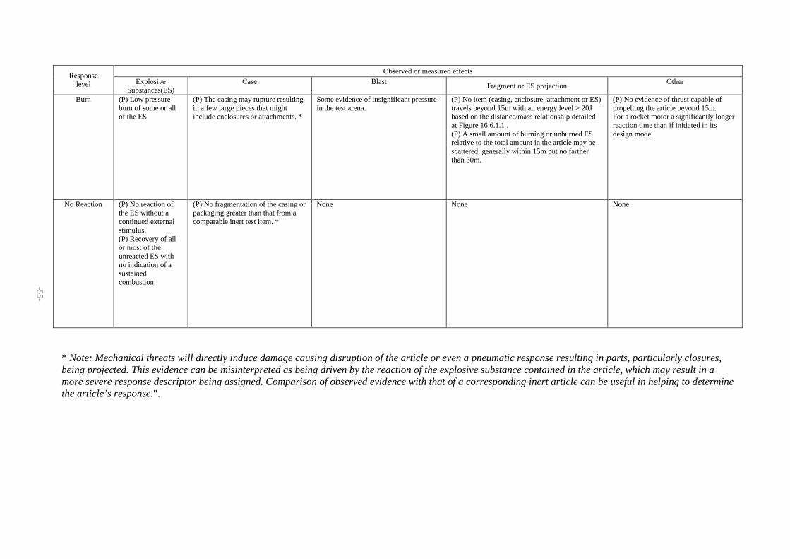
-55-
* Note: Mechanical threats will directly induce damage causing disruption of the article or even a pneumatic response resulting in parts, particularly closures, being projected. This evidence can be misinterpreted as being driven by the reaction of the explosive substance contained in the article, which may result in a more severe response descriptor being assigned. Comparison of observed evidence with that of a corresponding inert article can be useful in helping to determine the article’s response.".
Observed or measured effects Response
level Explosive Substances(ES)
Case
Blast
Fragment or ES projection Other
Burn (P) Low pressure
burn of some or all of the ES
(P) The casing may rupture resulting in a few large pieces that might include enclosures or attachments. *
Some evidence of insignificant pressure in the test arena.
(P) No item (casing, enclosure, attachment or ES) travels beyond 15m with an energy level > 20J based on the distance/mass relationship detailed at Figure 16.6.1.1 . (P) A small amount of burning or unburned ES relative to the total amount in the article may be scattered, generally within 15m but no farther than 30m.
(P) No evidence of thrust capable of propelling the article beyond 15m. For a rocket motor a significantly longer reaction time than if initiated in its design mode.
No Reaction (P) No reaction of the ES without a continued external stimulus. (P) Recovery of all or most of the unreacted ES with no indication of a sustained combustion.
(P) No fragmentation of the casing or packaging greater than that from a comparable inert test item. *
None None None