recommendations for csm and riso ground fault detector...
TRANSCRIPT
Recommendations for CSM and Riso Ground Fault Detector Trip Thresholds
Jack Flicker and Jay Johnson Sandia National Laboratories, Albuquerque, NM 87185, USA
Mark Albers
Sunpower Corporation, Richmond, CA 94804, USA
Greg Ball DNV GL-Energy, San Francisco, CA 94104, USA
Abstract — PV ground faults have caused many fires in the U.S. and around the world. One cause of these fires is a “blind spot” in the ground fault ground fault fuse.. As a result of this discovery, the Solar America Board for Codes and Standards identified a number of alternatives to ground fault fuses, but these technologies have limited historical use in the United States. This paper investigates the efficacy of two of these devices, isolation resistance monitoring (Riso) and current sense monitoring (CSM), in small (~3 kW) and large (>500 kW) arrays using both simulation and field data. The field data includes Riso and leakage current measurements of multiple PV systems, while the simulations include Riso and CSM measurements from various ground faults. From these results, it was found that the majority of leakage current is not from the modules, but from low inverter isolation-to-ground. Therefore appropriate thresholds to maximize detection area while minimizing nuisance tripping should be made based on the specific inverter isolation and switching noise rather than the configuration of the PV system.
Index Terms — Riso, RCD, SPICE, ground faults
I. INTRODUCTION
PV arc-faults and ground faults have caused many fires around the world. In cases of faults on rooftop systems, the resulting fire can burn down the building and put occupants’ lives at risk. Further, publicity surrounding these fires can change public perception of solar in harmful ways. The U.S.-Department of Energy-funded Solar America Board for Codes and Standards (Solar ABCs) steering committee investigated ground faults and the ground fault detection blind spot [3-5]. The conclusion of this work was that fuse-based GFDI (Ground Fault Detector/Interrupter) designs were vulnerable to faults to the grounded current-carrying conductor (CCC).
A GFDI cannot detect a fault on the grounded CCC, which could allow for unrestricted fault current flow—bypassing the GFDI—if a second fault is initiated anywhere in the array. This specific problem has caused multiple rooftop fires in the past [7]. A number of alternative technologies have been suggested [4], including isolation monitoring (Riso); residual current detection (RCD); and current sense monitoring/relay (CSM/R), but there is little experience with these technologies in the U.S.
CSMs operate by monitoring the current flow through the ground bond. Excessive current flow through the ground bond is assumed to be caused by a ground fault (not array and BOS component leakage) and the CSM trips.
Riso measurements are carried out on ungrounded systems (or grounded systems which temporary disconnect from earth ground during the measurement). This often occurs before the inverter begins to export power to the grid, so it is sometimes called a “morning check”. The Riso measurement is completed by injecting a voltage pulse on the CCCs with respect to ground using an external power source. The ground isolation can then be calculated from the current draw on the power source. If the isolation is below a certain threshold, the isolation monitor trips.
The range of detectable ground faults of both CSM and Riso measurements depend on the thresholds used to define the presence of a fault. If this trip threshold is too aggressive, there will be nuisance trips; but if the threshold is too passive, certain ground faults go undetected. Both CSM and Riso methods register array leakage current as a type of fault, therefore the detection threshold must be set above the maximum leakage current in all conditions (meteorological, configurational, and electrical) while also set low enough to detect the worst-case, lowest current faults possible in the array.
This paper discusses optimal thresholds for CSM and Riso measurements through a combination of SPICE simulations and experimental measurements on both small (~3 kW) and large (>500 kW) PV arrays. A proper understanding of detection thresholds maximizes the balance between system performance (uptime), reliability, and safety.
II. PV SIMULATIONS
Previous work has described, at length, the SPICE simulations used to analyze fault currents and detection areas in fuse protected PV systems. These simulations considered series, parallel, and ground faults for both arcing- and constant resistance-faults (which are electrically equivalent in the quasi-steady-state simulations) [3-5]. In addition to the “blind spot” on the grounded CCC, it was found that internal fuse resistances (especially at ratings below 1 A) have a significant
effect on measured GFDI fault current. As a result, reducing the ground fault fuse rating to a lower threshold does not necessarily improve the number of ground faults that can be detected. Therefore, it was suggested that fault detection schemes move away from fuse-based solutions towards Riso and CSM monitoring, which can be adjusted without affecting the fault current measurement. With both of these detection methods, more sophisticated detection thresholds are possible (e.g. derivative, step, integral) rather than a single, static limit.
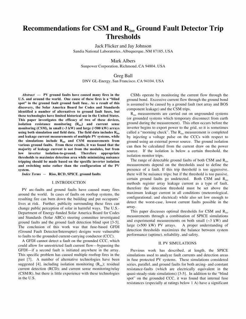
A. Isolation Resistance Fig. 1 shows the general electrical diagram of the SPICE
simulation for the isolation resistance (Riso) measurement. This schematic shows a two-string array with seven modules per string, though the number of strings and modules per string can be altered easily. The module IV characteristics were modeled to match the 200 W mono-crystalline Si modules located at the Distributed Energy Technologies Laboratory (DETL) at Sandia National Labs. Each module is modeled with some leakage resistance (Rleak) to ground through the equipment grounding conductor (EGC). A fault path with arbitrary impedance can be induced on any string at any electrical position on the string. In order to measure Riso, the grounded CCC is de-bonded from ground and a voltage pulse (typically ~50 V) is injected into the positive CCC. The Riso can then be calculated by measuring the current flow before (V=0) and during (V=Vapplied) the current pulse, as shown in Eq. (1):
Riso =Vapplied
I(Vapplied )− I(V = 0) (1)
Fig. 1. SPICE simulation of the Riso measurement to the positive CCC.
The leakage resistance to ground of each module can be modeled as an S✕M array of parallel resistors, where S is the number of strings in the array and M is the number of module per string [9]. In this case, under normal operation, the array isolation can be approximated by Eq. (2).
Risoarray =
RleakS ⋅M
+ REGC (2)
If a fault exists in the array, the parallel resistor equation must be modified to Eq. (3).
EGC
faultleak
arrayiso R
RRMS
R +
⎟⎟⎠
⎞⎜⎜⎝
⎛+
⋅=
1
1
(3)
Slight deviations between experimental measurements and equations (2) and (3) are due to voltage drops across parasitic resistors, bypass diodes, and/or the module photodiodes.
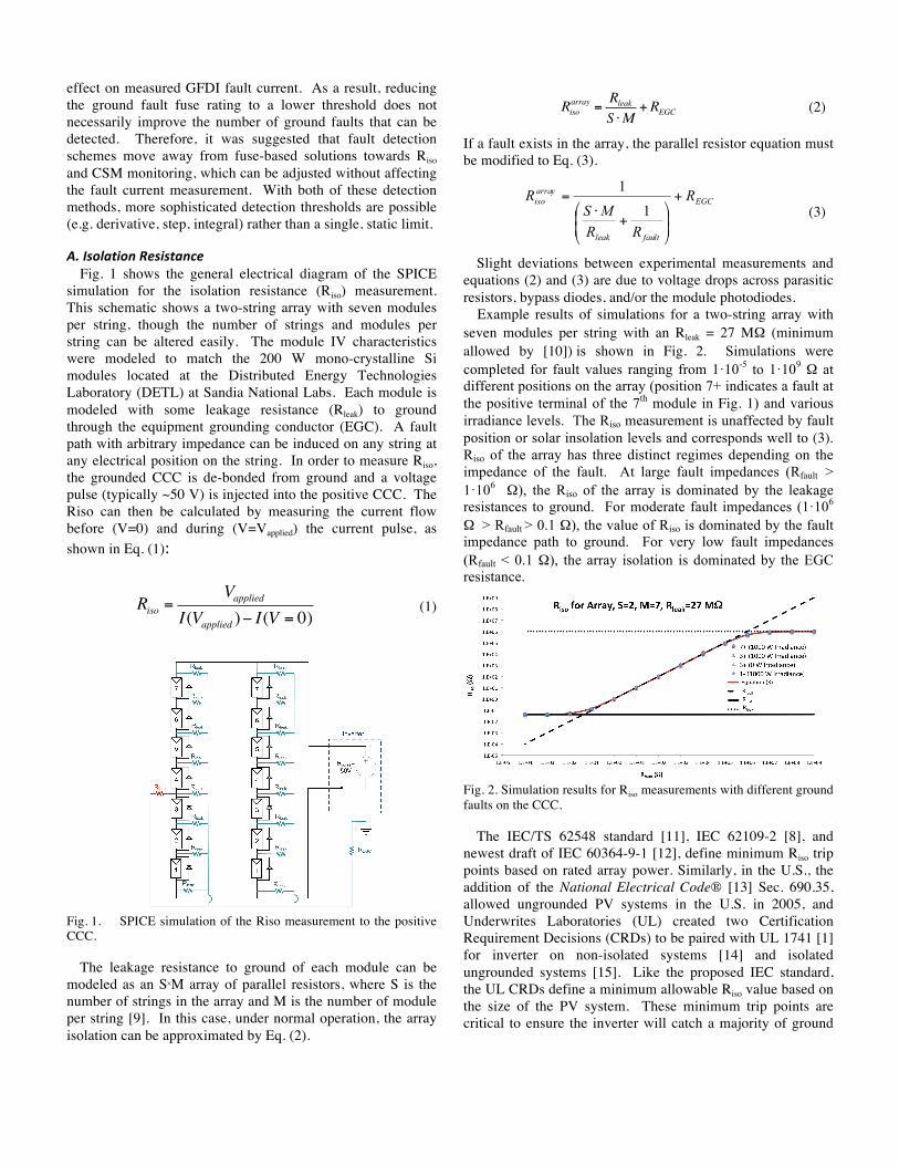
Example results of simulations for a two-string array with seven modules per string with an Rleak = 27 MΩ (minimum allowed by [10]) is shown in Fig. 2. Simulations were completed for fault values ranging from 1·10-5 to 1·109 Ω at different positions on the array (position 7+ indicates a fault at the positive terminal of the 7th module in Fig. 1) and various irradiance levels. The Riso measurement is unaffected by fault position or solar insolation levels and corresponds well to (3). Riso of the array has three distinct regimes depending on the impedance of the fault. At large fault impedances (Rfault > 1·106 Ω), the Riso of the array is dominated by the leakage resistances to ground. For moderate fault impedances (1·106 Ω > Rfault > 0.1 Ω), the value of Riso is dominated by the fault impedance path to ground. For very low fault impedances (Rfault < 0.1 Ω), the array isolation is dominated by the EGC resistance.
Fig. 2. Simulation results for Riso measurements with different ground faults on the CCC.
The IEC/TS 62548 standard [11], IEC 62109-2 [8], and newest draft of IEC 60364-9-1 [12], define minimum Riso trip points based on rated array power. Similarly, in the U.S., the addition of the National Electrical Code® [13] Sec. 690.35, allowed ungrounded PV systems in the U.S. in 2005, and Underwrites Laboratories (UL) created two Certification Requirement Decisions (CRDs) to be paired with UL 1741 [1] for inverter on non-isolated systems [14] and isolated ungrounded systems [15]. Like the proposed IEC standard, the UL CRDs define a minimum allowable Riso value based on the size of the PV system. These minimum trip points are critical to ensure the inverter will catch a majority of ground

faults, while still providing enough headroom to prevent nuisance tripping.
SPICE simulations were carried out to simulate arrays ranging from 20 to 600 kW (1.4 kW/string) for fault impedances ranging from 1·10-5 to 1·109 Ω . The results of these simulations are shown in Fig. 3; the maximum detectable ground fault resistance is shown by the black ‘x’ for different PV systems based on the thresholds defined in the IEC 62548 standard.
Fig. 3. Riso measurements for different system sizes and Rfault values (colored lines), the minimum isolation resistance values for different PV system sizes according to IEC 62548 (dashed lines), and the maximum fault resistance that would be detectable (line crossings marked by a black ‘x’).
B. CSM SPICE simulations using CSM measurements on arrays
ranging in size from 3-500 strings have been discussed at length in previous work [4, 16-18]. In short, SPICE simulations have been shown to accurately model the fault and leakage currents for a wide variety of fault locations, inverter behaviors, and fault impedances. However, the simulations only predict the current mean value of the system leakage and are unable to capture the detailed leakage waveform due to noise from inverter switching on the ground bond, which is the most important component to consider when determining proper thresholds to reduce unwanted tripping events while still maximizing the detection window.
Due to the historical method of detecting ground faults in the United States, the vast majority of grounded systems have a fuse to detect ground faults. However, the presence of this fuse and its added impedance in series with the fault resistance decreases the detection window of the system, especially for faults on the grounded current carrying conductor (CCC), leaving the system at risk of an undetected “blind-spot” fault. Therefore, in grounded systems with fusing, it is recommended that the fuse be sized according to maximum limit defined in UL 1741 to decrease the internal series resistance and prevent a decrease in the detection window while setting the CSM trip threshold to a lower value. This will protect the system against the greatest number of faults on the grounded CCC.
III. GROUND FAULT EXPERIMENTS
A. Isolation Resistance Megohmmeters were used to measure the Riso values of
multiple PV systems in the SunPower fleet. For an exemplary ungrounded system in North Carolina with 216-strings and a 760 kW inverter, the 5-minute isolation resistance values are shown in Fig. 4. The isolation resistance values were larger when the system was not exporting power than during daytime operation, with some secondary effects from weather and array electrical parameters, e.g., DC bus voltage. However, the clear driver for the isolation resistance was the operation of the inverter. When the inverter began operation in the morning, the isolation resistance was cut nearly in half—from ~350 kΩ to ~200 kΩ—as shown in Fig. 5. This indicates the component of the isolation resistance coming from the inverter was dominant compared to the array insulation.
SPICE simulations modeling the 216-string configuration corroborated the supposition that the isolation resistance of the system is controlled by the inverter isolation-to-ground rather than the module-to-ground isolation. In order to correctly model the day/night Riso behavior of the array, the simulations of the array had to assume an average module-to-ground isolation of 670 MΩ, while the inverter had an isolation-to-ground of only 750 kΩ, 1000-times smaller than the module isolation (Fig. 5). Additionally, it is interesting to note that the minimum isolation resistance from the 2160 modules (according to requirements in IEC 61215 [10]) would be 12.3 kΩ based on the module-to-frame isolation requirement of 40 MΩ·m2 and assuming module areas of 1.5 m2. However, modules typically have isolation values in the GΩ range, so the overall insulation resistance from the modules in a 760 kW array is in the upper kΩ or MΩ, as measured during the nighttime periods in Fig. 4.
Many inverters make isolation resistance measurements once a day during inverter startup and perform operational ground fault detection with a Ground Fault Detector/Interrupter (GFDI) fuse or CSM. In those systems, the reduction in isolation from inverter operation does not need to be taken into account and higher Riso thresholds can be used; however, for systems performing continuous or periodic Riso measurements with the inverter operating, the ground fault threshold must be set at a lower threshold or the Riso reduction from the inverter operation will trip the ground fault protection system. This continuous Riso monitoring system can only be used on ungrounded PV systems because a current or voltage pulse is superimposed on the nominally DC system bus during array operation.

Fig. 4. Riso measurements on a 760 kW system for eight days with array voltage, AC power, and daily precipitation totals.
Fig. 5. Riso decrease during inverter operation.
American and International standards for PV inverters define limits for Riso and CSM/RCD devices before they need to trip, as shown in Table I. Since the SunPower system in North Carolina has an ungrounded, transformerless inverter the UL 1741 Certification Requirement Decision (CRD) states that the inverter should trip when the resistance value drops below 100 kΩ (which would be sufficient to detect any fault with impedance ≤67.5 kΩ). The minimum isolation resistance measurement for this period was 164.0 kΩ , so the system is operating above the trip threshold; although the standard is designed for Riso checks prior to interconnection, so there is more headroom before a ground fault alarm is sounded. By comparision, IEC 62109-2 states that the ground fault detector should trip when the resistance of the array drops below 33.3 kΩ (which would be sufficient to detect any fault with impedance ≤40 kΩ), so it is more conservative with regard to avoiding nuisance tripping events. Based on the eight days of SunPower data, it seems the UL 1741 CRD requirements are superior because they will be able to detect higher impedance ground faults in the system, while still avoiding unwanted tripping from precipitation and other weather changes. However, other PV systems may not have the same isolation, and the more strict threshold could cause unwanted tripping.
B. CSM Array leakage is a function of a number of different effects ranging from module/inverter technology, balance of system components, array layout, and meteorological conditions.
Table I SUMMARY OF RISO AND CSM THRESHOLDS IN U.S. AND INTERNATIONAL STANDARDS
Standard AC-‐Isolation DC-‐Grounding Riso CSM or RCD
UL 1741, Ed. 2 [1] Yes (Transformer) Grounded
kW mA
0 -‐ 25 ≤1000 25 -‐ 50 ≤2000 50 -‐ 100 ≤3000 100 -‐ 250 ≤4000 >250 ≤5000
UL 1741 CRD 26-‐Apr-‐2010 [2] for Smax ≤30 kVA
No (Transformerless)
Floating
kVA kΩ mA Trip time (s)
≤5 The larger resistance of 100 kΩ or 1 kΩ * Vmax
300 continuous 0.30 30 step 0.30
>5 The larger resistance of
100 kΩ or 5 kΩ * Vmax/Smax 60 step 0.15 150 step 0.04
UL 1741 CRD 29-‐May-‐2012 [6]
Yes (Transformer) Floating
kVA Ω ≤30 500 +(Voc/300 mA) >30 500 +[Voc/(10 mA*Smax)]
IEC 62109-‐2, Ed. 1 [8]
No (Transformerless)
Floating [Vmax/30 mA] Ω
mA Trip time (s) ≤30 kVA = 300 mA RMS
(continuous) 0.30
>30 kVA = 10 mA RMS per kVA (continuous)
30 (step) 0.30 60 (step) 0.15 150 (step) 0.04
Yes (Transformer) Floating [Vmax/30 mA] Ω Yes (Transformer) Grounded
Vmax is the manufacturer rated maximum PV input voltage, Smax is the maximum rated inverter output apparent power in kVA, Voc is the open circuit voltage of the PV array, and kVA values are the rated continuous output power of the Equipment Under Test. RMS is root mean square.
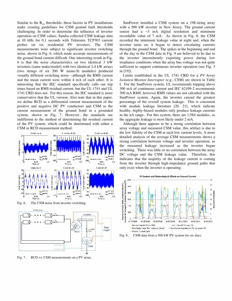
Similar to the Riso thresholds, these factors in PV installations make creating guidelines for CSM ground fault thresholds challenging. In order to determine the influence of inverter operation on CSM values, Sandia collected CSM leakage data at 10 kHz for 0.1 seconds with Tektronix TCP303 current probes on six residential PV inverters. The CSM measurements were subject to significant inverter switching noise, shown in Fig. 6, which made accurate measurements of the ground bond current difficult. One interesting result in Fig. 6 is that the noise characteristics on two identical 3 kW inverters (same make/model) with two identical 2.4 kW arrays (two strings of six 200 W mono-Si modules) produced visually different switching noise—although the RMS current and the mean current were within 4 mA of each other. It is interesting that the IEC standard specifically calls out trip times based on RMS residual current, but the UL 1741 and UL 1741 CRD does not. For this reason, the IEC standard is more conservative that the UL version. Also note that in this paper, we define RCD as a differential current measurement of the positive and negative DC PV conductors and CSM as the current measurement of the ground bond in a grounded system, shown in Fig. 7. However, the standards are indifferent to the method of determining the residual current of the PV system, which could be determined with either a CSM or RCD measurement method.
Fig. 6. The CSM noise from inverter switching.
Fig. 7. RCD vs. CSM measurements on a PV array.
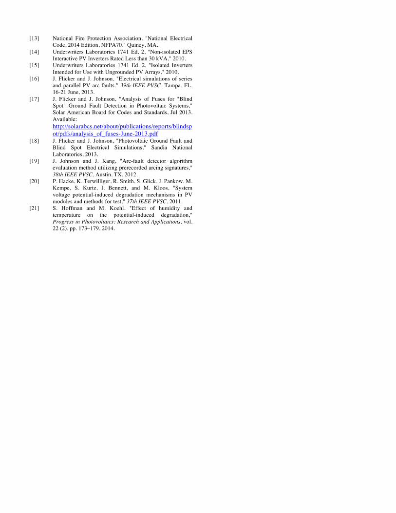
SunPower installed a CSM system on a 198-string array with a 500 kW inverter in New Jersey. The ground current sensor had a ~3 mA digital resolution and minimum recordable value of 7 mA. As shown in Fig. 8, the CSM recorded the minimum leakage value at night and, when the inverter turns on, it began to detect circulating currents through the ground bond. The spikes at the beginning and end of the day in the CSM data in Fig. 9 are believed to be due to the inverter intermittently exporting power during low irradiance conditions when the array bus voltage was not quite sufficient to support continuous inverter operation (see Fig. 3 in [19]).
Limits established in the UL 1741 CRD for a PV Array Isolation Monitor Interrupter (e.g., CSM) are shown in Table I. For the SunPower system, UL recommends tripping above 300 mA of continuous current and IEC 62109-2 recommends 300 mA RMS, however RMS values are not calculted with the SunPower system. Again, the inverter caused the greatest percentage of the overall system leakage. This is consistent with module leakage literature [20, 21], which indicate healthy, highly-biased modules only produce leakage currents in the nA range. For this system, there are 1,584 modules, so the aggregate leakage is most likely under 2 mA.
Although there appears to be a strong correlation between array voltage and measured CSM value, this artifact is due to the low fidelity of the CSM at such low current levels. A more detailed analysis of the average CSM measurements shows a strong correlation between voltage and inverter operation, as the measured leakage increased as the inverter began switching. There was little or no correlation between the array DC voltage and the CSM leakage value. Therefore, this indicates that the majority of the leakage current is coming from the inverter through high-impedance ground paths that only exist when the inverter is operating.
Fig. 8. CSM data from a 500 kW PV system for six days.

Fig. 9. CSM current increase during inverter operation.
CONCLUSIONS
In field measurements of Riso and their corresponding SPICE simulations it was found that inverter insulation-to-ground isolation (rather than module-to-ground isolation) dominated overall system isolation. In a 216-string, 760 kW array, the Riso behavior of the system could only be modeled if the inverter-to-ground isolation was around 1000-times smaller than the module-to-ground isolation. This indicates that system Riso measurements may vary widely from system to system depending on the type of inverter used.
Over the 8-day Riso monitoring of a 760 kW system, the isolation never dropped below 164.0 kΩ, which is above the threshold set by either the UL 1741 CRD (100 kΩ) or IEC 62109-2 (33.3 kΩ). Although both standards seem appropraite in this case, the CRD has a larger detection window. However, the UL CRD is less conservative with regards to unwanted tripping due to the inverter than the IEC standard, but both standards will work in this case and it is up to the operator to determine which to use through careful consideration of both detection window and unwanted tripping. In the future, the standards should be harmonized so that one single threshold value is required.
Although SPICE simulations can successfully predict average leakage and fault current values via CSM, it cannot describe the complicated current waveforms on the ground bond due to inverter switching schemes. Field measurements on the ground bond using CSM have shown that high impedance ground paths from the inverter again dominate the ground bond leakage current. Hence, determining proper CSM thresholds are difficult because of this inverter noise, which varies not only from inverter-type to inverter-type, but even among inverters of the same type. While the IEC standard specifically sites RMS leakage current, the UL CRD does not. Therefore the IEC is much more conservative with regard to unwanted tripping. The operator must have some knowledge of the detailed switching waveform and the characteristic level of ground bond noise vs. RMS leakage in order to determine which of these standards is most appropriate, as inverters which introduce large leakage spikes on the ground bond may cause tripping under UL standards, but not IEC.
ACKNOWLEDGEMENTS
This work was funded by the DOE Office of Energy Efficiency and Renewable Energy. Sandia National Laboratories is a multi-program laboratory managed and operated by Sandia Corporation, a wholly owned subsidiary of Lockheed Martin Corporation, for the U.S. Department of Energy's National Nuclear Security Administration under contract DE-AC04-94AL85000.
REFERENCES [1] Underwriters Laboratories 1741 Ed. 2, "Inverters,
Converters, Controllers and Interconnection System Equipment for Use With Distributed Energy Resources," 2010.
[2] Underwriters Laboratories 1741, "Certification Requirement Decision, Non-Isolated EPS Interactive PV Inverters Rated Less Than 30kVA," 26-April-2010.
[3] J. Flicker and J. Johnson, "Photovoltaic Ground Fault and Blind Spot Electrical Simulations " Sandia National Laboratories, 2013. Available: http://energy.sandia.gov/wp/wp-content/gallery/uploads/SAND2013-3459-Photovoltaic-Ground-Fault-and-Blind-Spot-Electrical-Simulations.pdf
[4] G. Ball, B. Brooks, J. Flicker, J. Johnson, A. Rosenthal, J. C. Wiles, and L. Sherwood, "Inverter ground-fault detection ‘blind spot’ and mitigation methods," Solar American Board for Codes and Standards, June 2013.
[5] J. Flicker and J. Johnson, "Analysis of Fuses for 'Blind Spot' Ground Fault Detection in Photovoltaic Systems," Solar American Board for Codes and Standards, July 2013. Available: http://solarabcs.net/about/publications/reports/blindspot/pdfs/analysis_of_fuses-June-2013.pdf
[6] Underwriters Laboratories 1741, "Certification Requirement Decision, Isolated Inverters Intended for Use with Ungrounded PV Arrays," 29-May-2012.
[7] B. Brooks, "The Ground-Fault Protection Blind Spot: Safety Concern for Larger PV Systems in the U.S.," Solar American Board for Codes and Standards, January 2012.
[8] International Electrotechnical Commission 62109-2 Ed. 1.0, "Safety of power converters for use in photovoltaic power systems - Part 2: Particular requirements for inverters." Geneva, 2011.
[9] SMA, "Insulation Resistance (Riso) of Non-Galvanically Isolated PV Plants, SMA Technical Information Note, Version 2.2," URL: http://files.sma.de/dl/7418/Riso-UEN123622.pdf, accessed 10 Feb 2014.
[10] International Electrotechnical Commission 61215, "Crystalline silicon terrestrial photovoltaic (PV) modules. Design qualification and type approval." Geneva, 2009.
[11] International Electrotechnical Commission 62548 Ed. 1.0, "Photovoltaic (PV) arrays - Design requirements," International Electrotechnical Commission, Geneva,Jul 2013.
[12] International Electrotechnical Commission 60364-9-1 Ed. 1.0, "Low-voltage electrical installations - Part 9-1: installation, design and safety requirements for photovoltaic systems (PV)." Geneva, Nov 2014.
[13] National Fire Protection Association, "National Electrical Code, 2014 Edition, NFPA70." Quincy, MA.
[14] Underwriters Laboratories 1741 Ed. 2, "Non-isolated EPS Interactive PV Inverters Rated Less than 30 kVA," 2010.
[15] Underwriters Laboratories 1741 Ed. 2, "Isolated Inverters Intended for Use with Ungrounded PV Arrays," 2010.
[16] J. Flicker and J. Johnson, "Electrical simulations of series and parallel PV arc-faults," 39th IEEE PVSC, Tampa, FL, 16-21 June, 2013.
[17] J. Flicker and J. Johnson, "Analysis of Fuses for "Blind Spot" Ground Fault Detection in Photovoltaic Systems," Solar American Board for Codes and Standards, Jul 2013. Available: http://solarabcs.net/about/publications/reports/blindspot/pdfs/analysis_of_fuses-June-2013.pdf
[18] J. Flicker and J. Johnson, "Photovoltaic Ground Fault and Blind Spot Electrical Simulations," Sandia National Laboratories, 2013.
[19] J. Johnson and J. Kang, "Arc-fault detector algorithm evaluation method utilizing prerecorded arcing signatures," 38th IEEE PVSC, Austin, TX, 2012.
[20] P. Hacke, K. Terwilliger, R. Smith, S. Glick, J. Pankow, M. Kempe, S. Kurtz, I. Bennett, and M. Kloos, "System voltage potential-induced degradation mechanisms in PV modules and methods for test," 37th IEEE PVSC, 2011.
[21] S. Hoffman and M. Koehl, "Effect of humidity and temperature on the potential-induced degradation," Progress in Photovoltaics: Research and Applications, vol. 22 (2), pp. 173–179, 2014.