recent developments in acip and dd piling - nesmith · recent developments in acip and dd piling...
TRANSCRIPT

1 HISTORY
1.1 Introduction
Today, augered, cast-in-place (ACIP) piles are widely accepted and installed with general guidelines for the design and construction of ACIP piles available, along with design references for specific geologies across the country. The evolution from introduction to mature technology has occurred over about seven decades. The patent application, “Method for Forming Piles” was filed by Raymond Patterson of Intrusion-Prepakt in 1951 and the patent was granted in 1956 (Figure 1). The method was developed as an offshoot of pressure grouting processes at the Intrusion-Prepakt firm. Typically a pipe was driven to a preset level at which point grout was injected under pressure. Augers were used to penetrate stiff or dense soils where the grout pipe could not be driven. Then the grout pipe was inserted next to the auger and grouting com-menced and the auger and pipe were withdrawn. As hollow-stem auger became available, the process was modified for piling to more closely resemble the process seen today.
1.2 Early Practitioners
Intrusion-Prepakt granted licenses in the late 1950s for installation of the patented piles to Berkel & Company Contractors, Inc. and the Lee Turzillo Contracting Company. The processes were known as; “Pakt-In-Place” for Intrusion-Prepakt, “Auger Pressure-Grouted” for Berkel and “Augercast” for Turzillo. “Augercast” has become a widely used generic term for the sys-tem and the industry term for the system (per the Deep Foundation Institute, DFI) is augered, cast in place.
Recent developments in ACIP and DD piling
W.M. NeSmith, Jr., P.E. Berkel & Company Contractors, Inc., Atlanta GA USA
ABSTRACT: Augered Cast-in-Place (ACIP) piles have been installed in the United States since the 1950s. There has been significant generational development in the years since in the areas of available equipment, construction materials, installation processes, performance testing, in-stallation monitoring and product acceptance.
This paper is a brief history of this development culminating in a summary of the current avail-able state-of-practice in the categories listed above. Specific emphasis will be given to the in-crease of the size and power of available equipment and its effect on the installation process (particularly the introduction of fixed-mast drilling equipment and the introduction of Drilled Displacement (DD) piles in the U.S.); the increase in availability of specialized construction materials; current industry guidelines for performance testing; and available methods for auto-mated and manual installation monitoring and their effect on the product acceptance process.

1.3 Development
The original patent for ACIP piles expired in the mid-1970s. ACIP piles saw a much wider exposure to different parts of the U.S. as a number of companies began to use the technology. The downside, however, is that this spread out the collection of practitioners who understood the process distinctions. The process can look deceptively easy and in fact, in terms of physics, an auger is a type of simple machine (a mechanical device that changes the direction or magni-tude of a force). But seasoned practitioners realize that their piles are greatly impacted by what might appear to be small changes in materials or procedures. As the evolution of the system has progressed, and the knowledge base in the geotechnical engineering community has increased, standards have been established to address these issues. References for static capacity analysis and quality control are now readily available as are standard specifications. The DFI published the first ACIP Pile Manual in 1990, which was updated in 2003 and is currently being updated again. In 2007, the Federal Highway Administration published, Geotechnical Engineering Cir-cular (GEC) No. 8, Design and Construction of Continuous Flight Auger Piles, which contains detailed descriptions of the equipment, processes and a number of design methods for both ACIP and drilled displacement (DD) piles.
Figure 1. Illustration from original patent.

2 EQUIPMENT, MATERIALS AND PROCESS
2.1 Original
The first power units were fairly low horsepower, only capable of generating about 15,000 ft-lbs of torque on the rotary head that drove auger rotation and penetration. Equipment was typically mounted on trucks or wagons and grout was placed with pneumatic pumps. Grout was batched on site from masonry sand, bagged cement, fly ash and a grouting agent. The fine ma-sonry sand used in the grout limited the available compressive strength to less than 3000 psi. Pile diameters were limited to less than 16-in diameter and pile lengths were similarly limited. Installation was typically less than 400 linear feet per day and the resulting piles were of rela-tively low capacity.
2.2 Current state of practice – ACIP
The available torque that could be generated has steadily increased to about 30,000 ft-lbs in the 1970s, 40,000 ft-lbs in the 1980s and on. Today, ACIP piles are installed by crane-supported, swinging lead systems (Figure 2). Power units with up to 850 horsepower are mounted on the back of crawler cranes (Figure 3) and can provide hydraulically operated top-head drives (Figure 4) with up to 90,000 ft-lbs of torque, which are a typical upper limit. Spe-cialty purpose-built gearboxes are available to provide up to 180,000 ft-lbs of torque but this requires larger, purpose built leads suspended from higher-capacity cranes.
Figure 2. Crane-mounted, swinging lead system and fixed mast platform in background

Crane Sizes (typical): 40 to 100 ton cranes most typical
40 ton crane - 40 ft of up to 18-in dia auger
60 ton crane - 60 ft of up to 18-in dia auger
100 ton crane - 100 ft of up to 18-in dia auger
150 ton crane - 100 ft of up to 36-in dia auger
Capacity and boom lengths vary with project
and site soil conditions
Figure 3. Crawler crane with power unit mounted on rear.
Grout is typically batched offsite (or in purpose-built on site facilities for very large projects)
and delivered in Ready-mix trucks. Grout with compressive strengths of up to 5,000 psi are considered typical in most parts of the U.S. with 6,000 psi to 7,000 psi becoming more widely available. Up to 9,000 psi grout can be delivered in very specific parts of the country. Grout is poured from the truck into the hopper of a hydraulically operated grout pump (Figure 5) and typically expelled under pressure (350 psi is typical) out the other end of the pump through a flexible hose that can transport the grout up to several hundred feet. Grout can be pumped at 0.4 cubic ft per stroke for small piles to up to 1.7 cubic feet per stroke for large piles.
Figure 4. Hydraulic gearbox Figure 5. Hydraulic grout pump
The increase in available grout strength has had a large impact on the ACIP pile market due to the code limits of allowable stress on bored piles (ACIP piles included). As of 2012, the most recent International Building Code limits the allowable stress on an ACIP pile to 0.3 times the unconfined compressive strength, ucs, (f’c) of the grout. Table 1 shows the maximum allowable loads permitted for various pile diameters using grout with a UCS of 4,000 psi. This could be considered typical of what ACIP piles might be used to resist in medium to dense or stiff soils.
Table 1. Maximum design loads for ACIP piles using 4,000 psi grout
Diameter: Max Design Load:
12-in 65 tons
14-in 90 tons
16-in 120 tons
18-in 150 tons
However, with the power now available for high-torque equipment, ACIP piles are routinely
being installed in highly over-consolidated glacial till, weathered rock, soft limestone (coastal areas) and some sedimentary rocks (soft shales and claystone). The additional geotechnical stiffness provided by these intermediate geomaterials or soft rock can be captured using higher strength grouts to permit additional load to be resisted by similar size piles. Table 2 shows a range of pile diameters with the maximum permissible loads using grout with a UCS of 6,000 psi.
Table 2. Maximum design loads for ACIP piles using 6,000 psi grout
Diameter: Max Design Load:
14-in 140 tons
16-in 180 tons
18-in 230 tons
24-in 405 tons
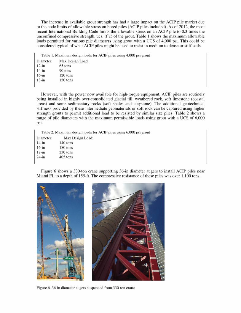
Figure 6 shows a 330-ton crane supporting 36-in diameter augers to install ACIP piles near
Miami FL to a depth of 155-ft. The compressive resistance of these piles was over 1,100 tons.
Figure 6. 36-in diameter augers suspended from 330-ton crane

A variety of reinforcing steel can be placed in the fluid grout after the pile is cast including large diameter center bars to permit resistance of large tension loads. Rebar cages of various size or steel pipes can be inserted to resist large lateral loads. Typically, most lateral loads can be resisted in the upper 20-ft to 30-ft, however seismic code or other local requirements may dictate longer reinforcing steel be installed. While installing long rebar cages or pipes may be challenging, recent developments in grout fluidifiers, retarders and water reducers has made it possible to install extremely long reinforcement in some geologies. Figure 7 shows the same project from Figure 6 with a 155-ft rebar cage suspended for insertion into the freshly cast pile.
Figure 7. 36-in diameter augers suspended from 330-ton crane
2.3 Current state of practice – drilled displacement
Drilled displacement (DD) piles were introduced in North America in the 1990s from Euro-pean screw-pile technology. As named, DD piles are installed by laterally displacing soil as the tool advances, rather than augering the soil to the surface. The installation of these piles re-quires powerful installation platforms which, in addition to providing high torque, also can ap-ply additional pull-down force to the tooling. Figure 8 is a schematic of a side-discharge, pres-sure-grouted displacement tool and a picture of the fixed-mast installation platform used to install these types of DD piles.

Figure 8. Schematic of DD pile tool and photo of fixed-mast drilling platform Typical installation platforms can apply 150,000 to 200,000 ft-lb of torque (larger equipment
with up to 400,000 ft-lb of torque is available) and 40,000 to 80,000 lb of downward force. They include the rigidly fixed mast for stability and an inclinometer with display in operator’s compartment. The general principle is the tool advances as a screw in low to medium consisten-cy soils. In dense soils, soil is transported up the auger to the displacing element. The soil in the auger flights is compressed and no stress relief occurs in the zone adjacent to the auger. When the target level has been reached, pumping of grout begins (Figure 8). Grout pressure measured at the top of the tools is monitored by the operator. Lift-off and withdrawal rate are varied to maintain pressure where possible. The tool is rotated during withdrawal and material which falls around stem is captured and displaced. Typically grout return is observed only after tip is at or near ground surface.
When DD piles are installed in soils that exhibit granular behavior, there is a significant in-
crease in density in the vicinity of the piles. The increase is most pronounced in loose to medi-um dense soils. After a certain density, as the in-situ density of the materials increases, the den-sity percentage change goes down. The increase in density is additive; i.e. the more piles that are installed, the greater the increase. Additionally there is no soil removed from the ground and it is easy to vary pile lengths to suit site conditions. Typical DD piles are 12-in to 18-in diame-ter, although 24-in DD piles have been installed. Piles of lengths of up to 100-ft have been in-stalled to date. The grout material and reinforcing steel available for DD piles is similar to ACIP piles. DD pile platforms and tooling are more expensive than ACIP pile equipment, but the geotechnical and environmental benefits outweigh these costs in some cases.
2.4 Current state of practice – continuous flight auger and partial displacement
As the availability of the fixed mast platforms used for DD pile installation increased in the U.S., the equipment has also been used to install fully flighted auger piles as well as partial drilled displacement piles. The author uses the term continuous flight auger (CFA) for the fully flighted auger piles to differentiate from the traditional ACIP piles (crane supported) piles in-stalled in the U.S. Photos of a 24-in diameter CFA pile setup and a 24-in partial DD pile tool are shown in Figure 9.

Figure 9. 24-in dia. CFA tool and fixed mast rig on left, 24-in partial DD pile tool on right.
The fixed-mast platforms can provide the force and torque for CFA tools to efficiently pene-trate drillable rocks (shale, sandstone, claystone) to provide large diameter, high capacity alter-natives to drilled shafts. Up to 42-in CFA piles have been installed in the U.S. Partial DD pile tools have large ratios of stem to flight diameter to remove some soil from the ground, while displacing some soil as well. The tool screwed into ground where possible (displacement) and drilled in where necessary (excavation) to improve loose soils and limit stress relief in dense soils. The tool shown in Figure 9 utilized soil dams to create an effective stem diameter of 18-in where the flight diameter is 24-in. The grout material and reinforcing steel available for CFA and partial DD piles is similar to ACIP piles.
3 PERFORMANCE TESTING
3.1 Static Load Tests
The following ASTM standards are applicable for static load testing of the piles described in this paper:
Compressive Load: D114-07 (Reapproved 2013) Tensile Load: D3689-07 (Reapproved 2013) Lateral Load: D3966-07 (Reapproved 2013) It should be noted that in the latest versions of both the compressive and tensile load stand-
ards consider the Quick Test method as Procedure A. There has been an increased recognition of the benefits of obtaining more data points to develop the applied-load vs. pile-head dis-placement relationship than are obtained through maintained test. The value of testing beyond two times the design load to either reach true bearing capacity (or obtain enough information to estimate capacity) has also been increasingly recognized. IBC 2012 lists three methods for evaluating load test results; Davisson Offset Limit (DOL), Brinch-Hansen 90% Criterion, and Butler-Hoy Criterion.

The IBC makes no distinction between pile types for the application of these methods, how-ever. The shortcomings of the DOL applied to cast-in-place piles are well known (NeSmith and Siegel, 2009). Stuedlein, et al (2014) recommend using the Butler-Hoy criteria to determine ul-timate load of APG piles. Figure 10 shows the results of a quick compression test with the available interpretation methods also shown. In this example, a modifier of 4 was used to esti-mate the ultimate load using the Davisson Offset Limit (DOL) as per his 1993 reference for ap-plying the DOL to cast-in-place piles. Further, the elastic line has been adjusted according to the recommendations of Kulhawy and Chen (2005).
Figure 10. Available IBC methods for evaluating pile capacity The use of center-bar mounted strain gages in compression test piles has increased in practice
and can provide excellent information on resistance to the load applied at the pile-head along the shaft and toe of the pile. This is particularly useful in layered profile and should strongly be considered in most compression load test programs. An example of a “sister bar” strain gage, intended to be tied or taped to the pile center-bar is shown in Figure 11.
Figure 11. Schematic of sister bar mounted strain gage (from Geokon)
Strain gages can also be used for tension load tests, however the center bars in these tests are
typically sleeved some distance (often 20-ft or more) to prevent the pile head from separating from the rest of the pile near the ground surface.

Thus, while the application point of a compression load test is known (the pile head), it can often be unclear where the load is being applied initially in a tension test. The resulting value of the information obtained can then be somewhat questionable. Strain gages can also be mounted on rebar cage reinforcement in lateral test piles. By aligning them on either side of the cage in the plane of loading, bending data can be obtained. The value of this data should be weighed against the cost of acquiring and implementing the instruments into the test pile program.
3.2 Dynamic Load Tests
ASTM standard D4945-12 is applicable for the high-strain dynamic load testing of the piles described in this paper. Typically, a ram of known weight (often 1 to 2 percent of the test load) is dropped from a series of increasing known heights and force and velocity records are record-ed from strain and acceleration sensors near the top of the pile. The Case Pile Wave Analysis Program (CAPWAP) is then used to estimate resistance and capacity. A simulated load-set curve that shows typical results from a series of increasing drop heights is presented in Figure 12.
Figure 12. Simulated load-set curve (from GRL Engineers, Inc.) The technology was originally developed to monitor and test driven piles and as shown in
the example, a typical driven pile load-displacement relationship (including a failure load) is generated at each drop height. Driven piles typically mobilize toe resistances almost immediate-ly while cast-in-place piles require significant mobilization of the pile head to generate mobili-zation of the pile toe. In the author’s experience, dynamic load test results can sometimes be correlated to the results of companion static tests and used for further testing during production on large projects where such testing is warranted. However, again in the author’s experience, they are typically not suitable as stand-alone tests for pre-production design verification testing of cast-in-place piles.
3.3 Osterberg Load Cells
Osterberg load cells (O-cells) are a patented technology consisting of a hydraulically driven loading device installed within the foundation unit. Load is applied upward to engage the shaft resistance of the pile and downward to engage the toe resistance of the pile (as well as any shaft resistance below the cell level) simultaneously. Strain gages are often incorporated into the pro-cess to evaluate load transfer along the pile shaft. O-cells range in capacities from 200 kips to 6,000 kips but multiple O-cells can be aligned to obtain higher test loads. An example of the O-cell setup is shown in Figure 13.

Figure 13. Schematic O-Cell setup (from Loadtest, Inc.)
3.4 StatnamicTM Load Tests
Statnamic Load Testing is a recognized test method by ASTM standard D7383-08. It in-volves dampening the force from a controlled explosion against a large reaction weight to rapid-ly (but not dynamically) apply force to the pile head. Head displacements are monitored and strain gages may be used as in static test piles. In the author’s experience, test results correlate more closely to the results of static load tests than the results from high-strain dynamic testing.
Figure 13. Schematic and Photo of Statnamic Test Setup (from Applied Foundation Testing)

4 INSTALLATION MONITORING
There are now a significant number of automated monitoring equipment (AME) systems available to augment manual installation monitoring. It should always be noted that AME can-not replace manual inspection but provides supplemental information to the pile installer and Inspector during pile installation. Typical AME for the piles discussed in this paper may consist of the following:
A Display Unit to display numerically and/or graphically the collected information from var-ious sensors. This unit should be mounted in the cab to provide immediate feedback to the crane operator. All AME data should be stored in electronic format and available for download for processing and/or possible further evaluation/final reporting.
A real time clock should be included in the display unit that shows time to the nearest sec-ond.
A depth sensor consisting of a rotary encoder on self-retracting cable spool attached to drill top or gear box or a spring loaded rotary encoder mounted on the gear box and in constant con-tact with the leads to monitor auger tip depth at all times during installation OR a proximity sensor mounted on the main winch calibrated to convert winch rotation to tool depth. Pile depth should be viewable on the Display Unit along with penetration and withdrawal rate, calculated from depth vs. time measurements.
Rotary Head Pressure Sensor to monitor the hydraulic pressure provided to the gearbox. This pressure can then be approximately converted to torque on some equipment. On other equipment, this relationship is more complex including both pressure and rotational speed.
Rotation Sensors consisting of a proximity switch on the rotary head/gearbox OR a meas-urement of the flow of hydraulic fluid pressure applied to the rotary head, calibrated with rota-tion rate so that rotation rate can be viewed on the Display Unit.
A Magnetic Flow Meter may be installed in the grout line near the drilling platform to meas-ure grout volume pumped. Note that flowmeters typically have exposed electrodes that must be in contact with the conductive fluid (grout). If non-conductive sand particles take up space on the surface of the electrode, this interferes with the flow of electrical current. If the amount of electrode in contact with the fluid is variable, calibration with pump strokes, and accurate flow measurement with the meter, is not possible. Some installers have noted difficulty in maintain-ing calibration in various geographic areas where cast in place piles are commonly installed. Where this is apparent, one should revert to counting strokes of the grout pump if there is diffi-culty in maintaining flowmeter calibration. In the author’s experience, grout volume from flowmeter data, should be calculated for depth increments of not less than 5-ft.
Grout Pressure Sensor (not typical) to monitor maximum and minimum grout pressure in the grout line. Although this not useful for volume versus depth measurement, this sensor can pos-sibly be used to estimate pump strokes in some systems and depending on grout/concrete vis-cosity, so the flowmeter volume can be converted into approximate volume per pump stroke to evaluate grout pump performance.
Real Time Remote Display to display numerically and/or graphically the collected infor-mation from various sensors, for real-time review by the Inspector or other designated repre-sentative of the owner. Alternatively, a Field Printer to make a hard copy of results for each pile once completed.
Most AME systems have software that allow for producing installation records for each pile.
An example record is shown on Figure 14. General project and pile parameters are presented on the upper portion of the record. The parameter versus time graph shows auger tip depth, grout flow rate, and KDK pressure. Grout pressure versus time is optional. The parameter versus depth graph shows (from left to right), tool penetration rate while drilling (black line) and with-drawl rate while grouting (brown dashed line), KDK pressure, Grout Flow Rate, Auger Rota-tion Speed and Incremental Grout Factor. For DD piles, grout pressure is measured at the top of the tooling instead measuring grout volume. This grout pressure would be displayed on the bot-tom right in lieu of the incremental grout volumes. Partial DD piles may be cast from either volume or pressure at the top of the tooling depending on local soil subsurface conditions.

Figure 14. Example AME installation record for ACIP and CFA piles (from Berkel)
5 NON-DESTRUCTIVE TESTING (NDT)
5.1 General
The integrity of production piles may be evaluated by one of a number of NDT methods to confirm final system acceptance. Any NDT method has pile types and subsurface conditions for which it may or may not be well suited. This should be considered on a project specific basis. A much more detailed discussion of NDT methods can be found in the, “Guideline for the Inter-pretation of Nondestructive Integrity Testing of Augered Cast-in-place Piles” prepared by the ACIP and DD Pile Committee Of The Deep Foundations Institute. It is noted that ALL NDT re-sults should be used as a guide for additional detailed evaluation of pile quality and NEVER as a stand-alone reason to reject a pile.

5.2 Impulse Echo (Sonic Echo) Method for low strain integrity testing
ASTM standard D5882-07 is applicable to low strain integrity testing. The impulse echo test
consists of producing a compression wave at the top of the pile and measuring the return of the wave which is reflected off of the pile toe, assuming the pile is uniform. The wave can also be partially reflected by changes in impedance within the pile shaft. It is considered that a change of impedance might be indicative of a change in pile diameter or grout quality. Typically, the wave is generated by using a hammer to strike the pile top and an accelerometer to measure the response. An example of the striking procedure and results obtained from the data collected are shown in Figure 15.
The test is limited in effectiveness at depths greater than 30 times the pile diameter which
limits the effectiveness in long ACIP and DD piles. More importantly, variations in pile diame-ter can limit the quality of the data obtained. For example, cast-in-place piles installed in soil profiles with soft upper soils will typically have nominal diameters greater than the plan diame-ter. As the diameter of the pile decreases back closer to plan in stiffer lower soils, reflections will occur and data beyond this point is often meaningless or worse, useless. This misreading of a return to nominal diameter as a potential reduction to less than plan is one of the most com-mon errors in the use of this testing method. It cannot be overstressed that results from this type of NDT procedure would NEVER constitute rejection of a pile, only an indication that pile rec-ords and local stratigraphy be examined more carefully. While the technology behind the meth-od is sound, the experience of the author has been that this is one of the most misunderstood and misused methods of NDT and, considering the limitations noted above, is not suitable for ACIP and DD piles unless performed by very competent practitioners with a thorough under-standing of procedure and the meaningfulness of the results.
Readers are strongly encouraged to refer to the referenced DFI document for a more com-
pressive presentation of the method and its limitations as well as the Impulse Response (Sonic Mobility) Method Impedance Log/Profile Analysis which are potential enhancements to the method described here.
Figure 15. Photo of Impulse Echo Test and Example Output (from GRL, Inc.)
2.5 Sonic Logging
Because of the generally small diameter of ACIP and DD piles compared to drilled shafts, sonic logging of the piles typically consists of single-hole (or downhole) sonic logging (SSL). The method consists of inserting a sonic probe into a water-filled PVC pipe attached to, and in-stalled with, the pile’s full-length center bar. The tube should be immediately filled with water upon placement into the pile.
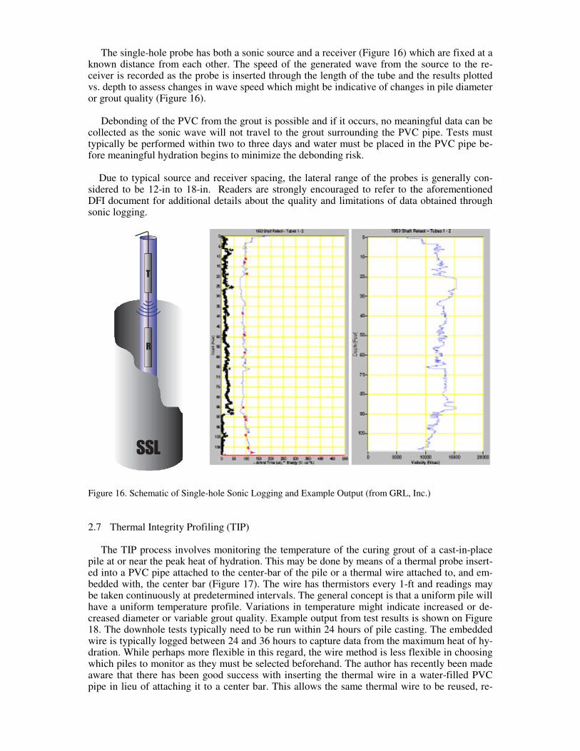
The single-hole probe has both a sonic source and a receiver (Figure 16) which are fixed at a known distance from each other. The speed of the generated wave from the source to the re-ceiver is recorded as the probe is inserted through the length of the tube and the results plotted vs. depth to assess changes in wave speed which might be indicative of changes in pile diameter or grout quality (Figure 16).
Debonding of the PVC from the grout is possible and if it occurs, no meaningful data can be
collected as the sonic wave will not travel to the grout surrounding the PVC pipe. Tests must typically be performed within two to three days and water must be placed in the PVC pipe be-fore meaningful hydration begins to minimize the debonding risk.
Due to typical source and receiver spacing, the lateral range of the probes is generally con-
sidered to be 12-in to 18-in. Readers are strongly encouraged to refer to the aforementioned DFI document for additional details about the quality and limitations of data obtained through sonic logging.
Figure 16. Schematic of Single-hole Sonic Logging and Example Output (from GRL, Inc.)
2.7 Thermal Integrity Profiling (TIP)
The TIP process involves monitoring the temperature of the curing grout of a cast-in-place pile at or near the peak heat of hydration. This may be done by means of a thermal probe insert-ed into a PVC pipe attached to the center-bar of the pile or a thermal wire attached to, and em-bedded with, the center bar (Figure 17). The wire has thermistors every 1-ft and readings may be taken continuously at predetermined intervals. The general concept is that a uniform pile will have a uniform temperature profile. Variations in temperature might indicate increased or de-creased diameter or variable grout quality. Example output from test results is shown on Figure 18. The downhole tests typically need to be run within 24 hours of pile casting. The embedded wire is typically logged between 24 and 36 hours to capture data from the maximum heat of hy-dration. While perhaps more flexible in this regard, the wire method is less flexible in choosing which piles to monitor as they must be selected beforehand. The author has recently been made aware that there has been good success with inserting the thermal wire in a water-filled PVC pipe in lieu of attaching it to a center bar. This allows the same thermal wire to be reused, re-

ducing cost. While relatively new, the author’s experience with TIP results has been very posi-tive.
Figure 17. Photos of downhole probe and wire-attached Thermal Integrity Profilers
Figure 18. Example output from Thermal Integrity Profiling (from GRL, Inc and Berkel)
6 ACKNOWLEDGEMENTS AND REFERENCES
The author and colleagues co-authored the article, “The Evolution of Cast in Place Piles” for the November/December 2013 DFI Magazine. This was the basis for the majority of the infor-mation presented herein regarding the history and early development of ACIP piles.
Additional references are as follows:
Brettmann, T., Hertlein, B., Piscsalko, G., Whitmire, B., Meyer, M. (2011), “Guideline for the Interpreta-tion of Nondestructive Integrity Testing of Augered Cast-in-place Piles” prepared by the ACIP and DD Pile Committee Of The Deep Foundations Institute.
Davisson, M.T. (1972) “High capacity piles”. Proceedings of the Lecture Series Innovations in Foundation Construction, ASCE, Illinois Section, 52 pp.
Davisson, M.T. (1993) “Negative skin friction in piles and design decisions” Proceedings, Third Interna-tional Conference on Case Histories in Geotechnical Engineering, St. Louis, 1793-1801.
Kulhawy, F.H. and Chen, J-R. (2005) “Axial compression behavior of augered cast-in-place piles in cohe-sionless soils” Advances in Deep Foundations, GSP 132, ASCE.
NeSmith, W.M. and Siegel, T. (2009). Shortcomings of the Davisson Offset Limit Applied to Axial Com-pressive Load Tests on Cast-in-Place Piles. Contemporary Topics in Deep Foundations. Selected Pa-pers from the 2009 IFCEE. GSP 185, pp. 568 – 574. Orlando FL, 15 – 19 March 2009.
Studlein, A.W., Reddy, S.C., Evans, T.M. (2014). “Interpretation of Augered Cast in Place Pile Capacity Using Static Loading Tests”. The Journal of the Deep Foundations Institute. Vol 8, No. 1, pp. 39 – 47. 09 June 2014