rec-erc-72-24 - bureau of reclamation · 2017-08-31 · rec-erc-72-24 influence of draft tube shape...
TRANSCRIPT

REC-ERC-72-24
Uldis J. Palde
Engineering and Research Center
Bureau of Reclamation
July 1972
,_ ., ....
;
' . ~ { .

MS-230 (8- 70) Bureau of Reclamation TECHNICAL REPORT STANDARD TITLE PAGE
1. REPORT NO .
REC-ERC-72-24
4. TITLE AND SUBTITLE
Influence of Draft Tube Shape on Surging Characteristics of Reaction Turbines
7. AUTHOR(S)
Uldis J. Palde
9. PERFORMING ORGANIZATION NAME AND ADDRESS
Engineering and Research Center Bureau of Reclamation Denver, Colorado 80225
12. SPONSORING AGENCY NAME AND ADDRESS
15. SUPPLEMENTARY NOTES
16. ABSTRACT
3. RECIPIENT'S CATALOG NO.
5. REPORT DATE
Jul 72 6. PERFORMING ORGANIZATION CODE
8. PERFORMING ORGANIZATION REPORT NO.
REC-ERC-72-24
10. WORK UNIT NO.
11. CONTRACT OR GRANT NO.
13. TYPE OF REPORT AND PERIOD COVERED
14. SPONSORING AGENCY CODE
Laboratory experiments, using a simplified air model, were conducted to obtain the correlation between draft tube shape and the draft tube surge characteristics-the range of occurrence, frequencies, and pressure amplitudes of the surges. Dimensionless parameters were used to compare results. The draft tube shape was found to have significant influence on the surging characteristics. Surge measurements obtained from two hydraulic turbine model studies are also compared using the dimensionless parameters. Hydraulic and air model studies of the same draft tube produced satisfactory correlation. The information presented can be used to predict the surge characteristics of prototype and model turbines, or as an aid in draft tube design where surge reduction or resonance minimization are considered as design criteria. Examples are included to illustrate application of the laboratory results.
17 . KEY WORDS AND DOCUMENT ANALYSIS
a. DES CR IP TORS-· I *draft tubes/ turbines/ *surges/ *hydroelectric powerplants/ hydraulic machinery/ fluid mechanics/ dimensional analysis/ model tests/ fluid flow/ pressure/ frequency/ *shape/ resonance/ test results/ hydraulic design/ *reaction turbines/ hydraulic turbines/ noise (sound)/ hydraulic models/ vibration/ wicket gates/ hydraulic similitude
b. IDENTIFIERS- - I hydraulic pressure tests/ Fontenelle Dam, Wyo/ Grand Coulee Powerplant, Wash/ water pressure tests
c . COSATI Field / Group 13G
18. DISTRIBUTION STATEMENT
Available from the National Technical Information Service , Operations Division, Springfield, Virginia 22151 .
19 . SECURITY CLASS 1. NO. OF PAGE (TH IS RE PORT)
UNCLASSIFIED 29 20 . SECURITY CLASS 22. PRICE
(THI S PAGE)
UNCLASSIFIED
..

REC-ERC-72-24
INFLUENCE OF DRAFT TUBE SHAPE
ON SURGING CHARACTERISTICS OF REACTION TURBINES
by Uldis J. Palde
July 1972
Hydraulics Branch Division of General Research Engineering and Research Center Denver, Colorado
UNITED STATES DEPARTMENT OF THE INTERIOR Rogers C. B. Morton Secretary
* BUREAU OF RECLAMATION Ellis L. Armstrong Commissioner

ACKNOWLEDGMENT
The study was conducted under the supervision of Dr. Henry T. Falvey, Head, Hydraulics Research Section, whose advice, encouragement, and patience is greatly appreciated. Appreciation is also expressed to Dr. Jack C. Cassidy (presently Head of the Civil Engineering Department, University of Missouri at Columbia) who patiently introduced the author to the draft tube surge phenomenon and its measurement in the laboratory. The help of Robert H. Kuemmich in resolving instrumentation problems is also appreciated. The entire research project was under the direction of William E. Wagner, Hydraulics Branch Chief, Engineering and Research Center, Denver.
Notation Conclusions Applications Introduction Analysis Laboratory iylq_del Laboratory Procedure Draft Tube Shapes Studied Results • • • • . . Surge Measurements on Turbine Models
CONTENTS
Air Model and Hydraulic Turbine Model Comparison Application to Turbines References Appendix .••.•
Page
ii 1 1 1 2 3 4 4 5 7 7
23 26 27

n
nu
p
P11
p'
a 011
R
s T
V
V
1T
p
0
n
Subscripts
m
p
NOTATION
height of wicket gates
runner diameter at minimum opening
diameter of draft tube throat
frequency (hz)
acceleration due to gravity
net head across turbine
length of draft tube
number of wicket gates
rotational speed (rev/min)
unit speed
power
specific power
pressure surge amplitude fluctuation from mean
discharge
specific discharge
radial distance to center of flow through wicket gates
width of opening between wicket gates
torque
axial velocity
radial inclination of flow through wicket gates
ratio of maximum runner rotational velocity to the spouting velocity
kinematic viscosity
3.1416
fluid density
turbine cavitation number
flux of moment of momentum
angular velocity (rad/sec)
functions
Reynolds number
model
prototype
ii

CONCLUSIONS
1. An air model of the type described in this report can successfully be used to determine the surging characteristics of hydraulic turbine draft tubes. The equipment need have no more mechanical components than the minimum required to precisely introduce, control, and measure swirling flow at the draft tube inlet.
2. The shape of the draft tube has a significant influence on the surging characteristics-the range of surging, the frequency band of the surges, and the arnplitude of the resulting pressure pulsations.
3. The throat geometry generally has more influence on the surging characteristics than the shape of the remaining downstream portion of the draft tube.
4. The degree of divergence of a draft tube is the most significant geometric feature affecting surging characteristics. Bends and relative length have lesser influence.
5. Surging can be minimized by using an equivalent draft tube expansion angle of about 15° through the whole length of the draft tube, and possibly eliminated entirely with greater angles.
6. The use of straight cylinder sections (any L/D) or constant diameter elbows in or near the draft tube throat will increase the range of surging and generally increase the frequency and amplitude of the surges.
7. The possibility of resonance with known natural frequencies of other features of the hydroelectric plant can be checked with fair accuracy using the results presented, if the turbine performance characteristics and wicket gate geometry are known. Resonance can be avoided by proper choice of geometric components in the draft tube design.
APPLICATIONS
The results presented in this report can be used to predict with fair accuracy the range of occurrence, frequencies, and pressure amplitudes of draft tube surges in prototype or model turbines. The draft tube shape and performance characteristics of the turbine must be known. The results can be used in draft tube design to help minimize the inevitable surging that will occur over some portion of the operating range of the turbine. Examples of dimensionless parameter
*Numbers indicate references at end of report.
evaluation are included to encourage the generalized comparison of surge measurement data obtained from prototype and model turbines.
INTRODUCTION
Draft tube surges have created problems in hydroelectric powerplants using reaction turbines for several decades. 1 *
Draft tube surges generally occur over a range of gate positions above or below best efficiency. The most common adverse effects of the surges are noticeable vibration and pounding noise in the powerplant. More serious manifestations, such as periodic variations in power output (power swings), vertical movement of the runner and shaft, and penstock pressure pulsations and vibration have often been attributed to draft tube sur9es.
For many years, there was considerable speculation and disagreement about the cause of draft tube surges. It is now generally accepted that the draft tube surge is a hydrodynamic instability which occurs in the draft tube as the result of rotation remaining in the fluid as it leaves the turbine runner and enters the draft tube throat. The hydrodynamic instability produces spiralling vortex flow in the draft tube, which has been referred to in the literature as "vortex breakdown."
Bureau of Reclamation powerplants have not been an exception to the draft tube surge problem. As a first step in ·finding a solution to the problem, a concentrated research effort was directed toward determining the basic nature and cause of draft tube surges. A bibliography of literature pertaining to draft tube surges and swirling flow in tubes was collected. An analysis and experimental investigation was conducted to gain an understanding of draft tube surging and to correlate occurrence, frequency, and amplitude of the surges with flow and geometric variables related to the flow through the turbine and draft tube. The experimental investigation was reported in a USBR report by Cassidy2 while the review of existing knowledge and an annotated bibliography was compiled in another USBR report by Falvey. 1 Specific aspects of the studies were also presented in two papers by Cassidy and Falvey.3' 4
Cassidy2 noted that the dimensionless parameters used to correlate the occurrence, frequency, and amplitude of the surges were also functions of the draft tube shape. The results indicated that a thorough

investigation of this aspect would be of great value in understanding the surge phenomenon, in predicting frequencies, and in applying measures to reduce or eliminate the surges. The experimental work presented in this report is a continuation and expansion of Cassidy's studies. The same experimental equipment and analysis were used. However, all results are from original data obtained subsequent to C~ssidy's studies.
This report contains sufficient analysis and description of experimental equipment· and procedure to provide an ample background for the analysis and application of experimental results. For a more thorough discussion of the analysis and description of the experimental equipment, the reader should refer to reference,2 while background information on problems arising from draft tube surges and attempts to solve them can be obtained from reference. 1
ANALYSIS
Dimensionless parameters were derived by Falvey and Cassidy4 to help generalize experimental results of surging flow in a draft tube. It was assumed that for a particular draft tube shape, the frequency f and root-mean-square (rms) amplitude
of the surge are both functions of the density p and the viscosity v of the fluid, the diameter D3 and length L of the draft tube, the discharge Q, and the flux of the moment of momentum (angular momentum)n. Dimensional analysis yielded the following functional relationships:
pressure parameter
and frequency parameter
mi = ( no3 .!:_ R) a r/>2 pa2 • D3 •
Where R is the Reynolds number 4QhrD3 v. The ratio no3 /p02 is referred to as the momentum parameter and is a ratio of angular momentum flux to linear momentum flux. The momentum parameter is, in effect, a useful measure of the amount of swirl in the flow. In applying it to the experimental study, the
2
assumption was made that regardless of the manner in which angular momentum is introduced into the flow, the resulting surging characteristics will be the same for a particular value of .QD3 /pQ2 . The frequency parameter is a form on the Strauhal number fD3/V (V is the axial velocity). written in terms of discharge.
Based on his initial experimentation with a simplified model using air as the fluid, Cassidy2 concluded that:
1. For a given draft tube shape there is a critical value of .QD3 /pQ2 above which surging flow exists.
2. The frequency and pressure parameters can be correlated with the momentum parameter for a given draft tube shape.
3. Frequency and rms pressure values of the surging flow are independent of viscous effects for Reynolds numbers above approximately 80,000 (prototype Reynolds numbers greatly exceed 80,000).
The momentum parameter no3 /pQ2 can be computed for a turbine if the runner diameter, wicket gate geometry, and the performance characteristics are known. If we start with the basic expression for power,
P= wT ( 1)
where w is the angular velocity and T is torque, and substitute
(2)
where n 1 - n2 is the rate of change of moment of momentum of the flow as it passes through the runner, we obtain
(3)
Multiplying Equation (3) by D3 /pQ2 and rearranging terms,
(4)
The left side of Equation (4) is the momentum parameter associated with the flow at the draft tube throat. The first term on the right of the same equation is the momentum parameter of the flow leaving the wicket gates and entering the turbine runner and can be computed by

il1 03 _ 0 3 R sina: pQ2 - BNS (5)
Equation (5) shows that il1 0 3 /pQ2 is entirely a function of wicket gate geometric variables (defined in Figure 1), and the draft tube throat diameter.
B • depth of gote N = no. of got es \ \
Figure 1. Definition sketch of flow leaving wicket gates and entering turbine runner.
The second term of Equation (4) can be computed from performance characteristics of the turbine, using the equation
= 550 P11 03 2y'2gpOi1 </>02
(6)
Where <I> is the ratio of maximum runner rotational velocity to the spouting velocity (the computed velocity obtained from a velocity head equal to the net head), or
P11 is the specific power, or
and 0 11 is specific discharge, or
Combining Equations (4), (5), and (6), we obtain
il2 0 3 _ 0 3 R sina: pQ2 - BNS
550 P11 03 2y2gp Oj1 </> 02
(7)
(8)
(9)
(10)
3
which can be evaluated for prototype or model turbines from data (in English units) normally obtained during performance tests.
LABORATORY MODEL
Laboratory experiments were conducted with air as the fluid and a model (Figure 2) utilizing some of the components of a model turbine which had been used in a prior hydraulic model study. The spiral case, stay vanes, and runner were removed. The wicket gates remained and served to produce swirl in the flow as it passed from a symmetrical pressure chamber into the draft tube (Figure 3). Radial inclination of the gates could be set at any angle between o0 (radial) and 82° (closed) to introduce varying amount of swirl in the flow.
Figure 2. Laboratory air model and instruments. Photo PX-0-67575
SECTIONAL PLAN SECTION THROUGH
WICKET GATES
Figure 3. Schematic of laboratory air model.

The momentum parameter of the flow entering the draft tube could be determined in the simplified laboratory model with far less effort than would be required in a complete turbine model. Without the turbine runner, the momentum parameter at the draft tube throat is equal to that existing in the flow leaving the wicket gates. Equation (5) could therefore be used to compute the momentum parameter of the flow entering the draft tube:
The computation of the pressure and frequency parameters required the measurement of discharge and the frequency and rms pressure of the draft tube surges. The rate of discharge was controlled at the wicket gate openings and varied along with the gate opening area with changes in the gate setting. The discharge was measured by a differential orifice located in the inlet pipe to the pressure box. Pressure differential across the orifice was measured with a pressure cell and conditioned by and recorded on one channel of a dual channel recorder-amplifier.
The plastic draft tubes being tested had piezometer taps at several locations along the walls. A pressure cell with a short piece of flexible tubing could be attached to the piezometers for dynamic pressure pickup. The signal was conditioned by the second channel of the recorder-amplifier and fed through a band-pass filter to an oscilloscope and rms meter. Frequencies of the periodic pressure pulsations were determined on the retentive screen of the oscilloscope. The instrumentation is shown in Figure 2.
LABORATORY PROCEDURE
The values of R, S, and o:, defined in Figure 1, vary with the gate position. These quantities were carefully measured or graphically determined for numerous gate angle settings, and tables for use in computations were prepared from smoothed curves of R, S, and o: versus gate angle. The value of the momentum parameter for a particular gate setting could then be readily computed using Equation (5).
For a particular draft tube, the range of gate settings for which surging flow could be detected was first noted, as well as the approximate maximum and minimum frequencies in that range. If the frequency band was not too great, the high- and low-pass circuits on the band-pass filter were set somewhat outside this band. Occasionally the frequencies varied greatly and
4
the band pass was set to include most of the frequencies encountered, and later adjusted as required.
For a particular gate setting, a given draft tube surges at the same frequency throughout the entire tube (with a few notable exceptions). The amplitude, however, varies with location along the tube wall. Data were generally taken at a location where amplitude was maximum, since the frequency was best defined at that location.
For some tubes, data were obtained at several locations to determine the variation of amplitude with respect to location. For one draft tube, data were also obtained at several locations without feeding the signal through the band-pass filter, for comparison of rms pressures with the filtered signal results.
A run consisted of frequency and rms pressure measurements (along with discharge orifice pressure differential) taken at the same piezometer at numerous gate settings in the range of surging. The data, along with amplifier attenuation factors, air density, and descriptive information were recorded on data sheets suitable for ADP card keypunch use. The dimensionless parameters and other flow variables were then determined by computer. During the computer run, frequency and pressure parameter versus momentum parameter curves could be plotted on an online cathode-ray tube (CRT) and photographed on 35mm microfilm for later copying and convenient storage. The CRT plotting routine was designed so that any six frequency or pressure parameter curves, each with a different symbol, could be plotted on the same figure (microfilm frame) by simply specifying the desired run numbers for each figure. The graphs used in Figures 4 through 18 (following Results section) are computer generated.
DRAFT TUBE SHAPES STUDIED
Cassidy2 determined that the draft tube shape definitely has an effect on the range of surging and on the frequency and rms pressure on the pulsations. His testing was limited to one model draft tube, an irregularly expanding cone, and several cylinders of varying diameter and length. From the results, it was not possible to extrapolate what shapes could eliminate or at least reduce the surging.
A systematic study to correlate the geometric shape components found in typical draft tubes with the surging characteristics was undertaken. A few of the shapes tested were actual models of draft tubes with

minor modifications. The greater majority, however, were simple geometrical shapes or combinations thereof, consisting of straight circular cylinders, truncated diverging cones, and circular cross-section elbows. The diameter, length, and angle of divergence were varied. Tests were repeated on all of the tubes which had already been tested by Cassidy2 to provide a reliable base of comparison, since measurement instrument calibration discrepancies were discovered later.
Data were eventually obtained for about 75 distinct draft tube shapes (see Figure 1 in the Appendix). Only a fractio·n are included in the comparison of results· which follow. The results that have been included generally reflect how different shapes or minor modifications have significant influence on the surging characteristics; they also show that some significant features, changes, or modifications have very minor, if any, influence. Many of these results were contrary to what might be expected or is presently assumed in draft tube design.
A minor limitation on the shapes that could be tested was imposed by the model itself. The downstream face of the pressure chamber had a thickness of 1.93 inches (4.9 centimeter (cm)) (see Figure 3), in which a permanent circular opening of 6.13 inches (15.6 cm) in diameter was provided for the outflow. Although the size of this opening could not be increased, it could be decreased. Or the shape could be changed (with the inevitable reduction of inlet diameterl by positioning a machined plastic insert of the required dimensions in the opening. Many of the tubes tested had inlet diameters of approximately 6 inches (15 cm).
The results presented by Cassidy2 and much of the data obtained initially in this study were taken on &-inch-diameter draft tubes, attached to the outer face of the pressure box. Consideration was not given to the short circular cylinder as a geometrical component upstream of the shape being tested. Subsequently, it was discovered that the upstream cylindrical section had significant influence on the surging characteristics. Much of the data for this condition was thus obtained unintentionally. But the data proved to be of value, as reflected in some of the included comparisons of results.
RESULTS
The presented results should be considered largely for their qualitative comparisons. The onset of surging was only seldom discernable as a well-defined break in the flow regime, and was therefore usually subject to the
5
investigator's interpretation. Rms pressure values were repeatable from day to day only within about a 10 percent variation. The values were also influenced by the frequency band pass used and somewhat by the presence of the short length of flexible tubing between the piezometer and pressure cell (producing a fairly constant amplification of about 13 percent). Pressure parameter curves should therefore be used primarily to indicate trends and the order of magnitude of the surges.
Frequencies in most cases could be precisely determined and were closely repeatable from day to day for the same draft tube and gate setting. The values of the resulting frequency parameter can therefore. -be used in a quantitative sense.
The results are presented as plots of the dimensionless parameters in Figures 4 through 18 (starting with page 8). In most cases, the surging characteristics of several shapes are compared in the same figure. Scaled schematic drawings (with only significant dimensions shown) of the shapes being compared are included in each figure. The symbol used for a tube in the parameter plots has been indicated on each draft tube at the location where the surges were measured. The run number has also been indicated adjacent to the symbol. Approximate distances along the tubes can be scaled. The range of surging is defined by the range of the momentum over which data points are plotted.
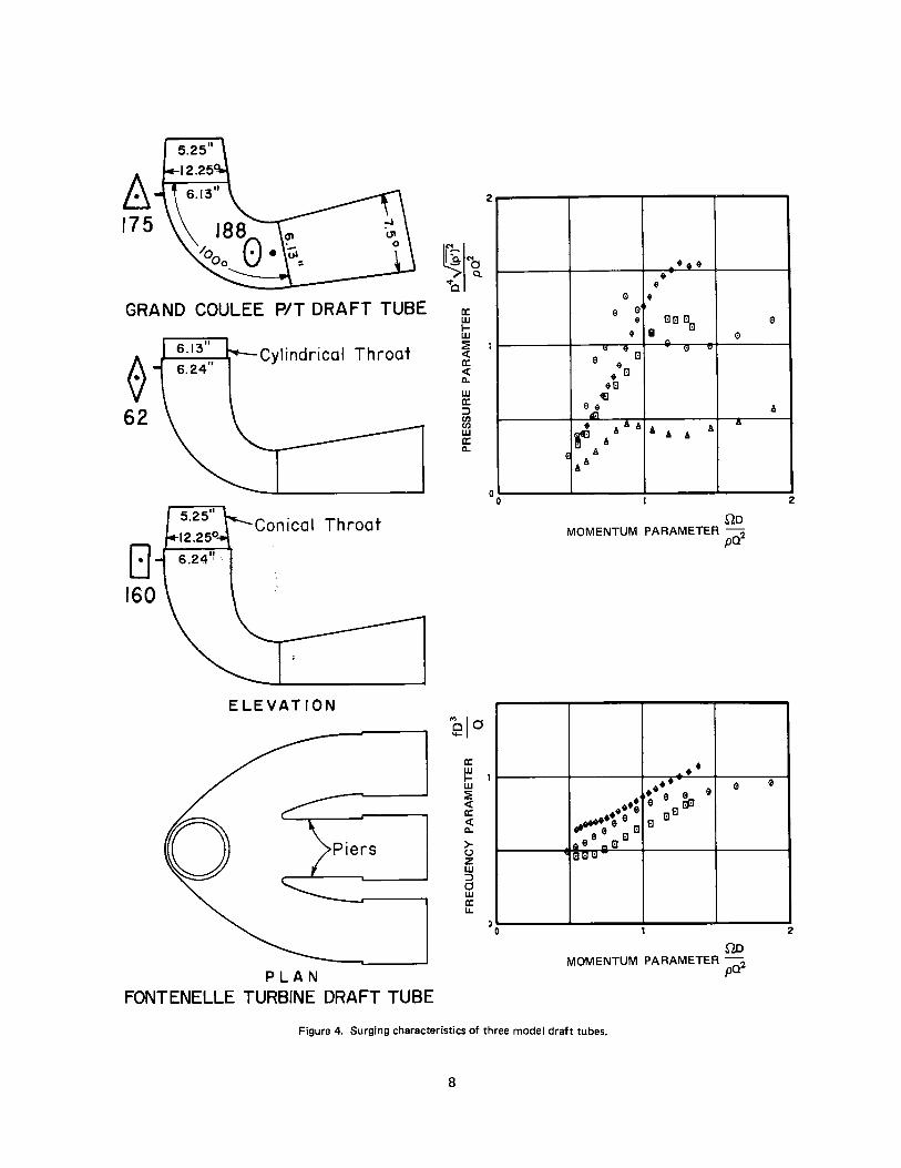
Figure 4 shows the surging characteristics of three draft tubes. The throats of both variations of the Fontenelle draft tube were modified from the actual prototype geometry. The Grand Coulee pump-turbine draft tube is geometrically similar to the prototype. Its cross section is circular for the entire length.
For all three draft tubes the frequency and pressure parameters initially increase with an increase of the momentum parameter. This was typical of all tubes tested. For some tubes, the pressure parameter continues increasing monotonously, while for others one or more peaks occur.
Most tubes surge over a finite range of momentum parameter, as is the case with the two variations of the Fontenelle draft tube. Others, like the Grand Coulee pump-turbine draft tube, surge continuously up to the point of complete wicket gate closure, where the momentum parameter approaches infinity. In the Grand Coulee pump-turbine draft tube, the maximum amplitudes occur near the end of the elbow, on the right side, where the amplitudes are much higher than at the start of the elbow (compare Runs 188 and 175, Figure 4). Although the pressure parameter generally attains the highest value at large values of momentum parameter (>2), the maximum value of the pressure pulsation amplitude itself usually occurs at a

momentum parameter value near 1, at the first peak of the pressure parameter.
A slight variation of the Fontenelle throat geometry produces significant changes in the surge parameter values but does not change the range of surging. Removal of the piers and progressively sections of the downstream end of the draft tube has little effect on the surge parameters. A short tube including only the first 30° of the elbow has only slightly different characteristics than the entire draft tube (see Figure 5).
Simple sections of truncated 15° cones surge over a smaller range of momentum parameter and display lower frequencies and amplitudes than the draft tubes (see Figure 6). The frequencies measured from the cones were far less well defined than those from any other shape. Different inlet diameters and L/D ratios have only slight effect on the dimensionless surge parameters. Figure 6 also verifies the validity of the dimensional analysis as related to geometric similarity.
Somewhat varying surging characteristics are displayed by 7.5° cones with variation of cone L/D (Figure 7). The longest and shortest tubes display surging ranges and frequency and pressure parameter curves quite similar to those of the Fontenelle draft tube. The surging range of the cone with L/D = 2.32, however, is far greater than the ranges of the other cones. The pressure parameter also increases continuously to higher values than for the other cones. It should be not~ that a 7.5° cone with L/D ~ 2.0 is used downstream of the constant-diameter elbow in the Grand Coulee pump-turbine draft tube.
Straight cylindrical tubes display surging characteristics quite different from those of expanding cones (see Figure 8). Short sections (LID <1) produce high-frequency curves, while longer sections have two distinct frequencies-the higher being exactly double the lower. In a tube having an L/D of 0.96 the lower frequency predominates up to a momentum parameter value of about 2.0, while beyond this point only the higher frequency is apparent (Runs 109 and 110). Several other intermediate lengths between L/D = 0.96 and L/D = 3.58 were tested. The tubes all had surge characteristics similar to the tube with L/D = 3.58. It should be noted that both high- and low-frequency parameter curves of all cylinders show considerably higher values than those of draft tubes with expanding sections.
Adding a bellmouth entrance section to a long, straight cylinder does not alter the surging characteristics up to a momentum pa(ameter value of about 2.0 (see Figure
6
9). The Reynolds number falls below 80,000 at momentum parameter values above about 1.8, and only results below this value should be considered. The bellmouth entrance possibly affects the distribution of the angular momentum at the entrance to the cylindrical section, but apparently does not change the total flux. The results tend to support the assumption that the manner of introduction of angular momentum is not significant.
Figure 10 illustrates the effect of adding short circular cylinders to the upstream end of a long 7.5° cone. The frequency and the range of surging are increased significantly as the length of cylinder is increased. Similar results were noted with the shorter 7.5° cones.
Adding circular cylinder sections upstream of a 15° cone has an even more pronounced effect on the surge characteristics (see Figure 11 ). A long cylinder has only slightly more influence than a short cylinder. Adding a cylinder to the downstream end of a long cone has no effect on the frequency, but does decrease the surge amplitude at higher momentum parameter values (Figure 11, Run 123).
The surge amplitude decreases with respect to distance from the inlet in an expanding cone, but generally increases in a long cylinder (Figure 12).
A 100° elbow produces lower frequencies than a cylinder of the same length (Figure 13). The range of surging is also reduced. In elbows of different lengths the highest pressure fluctuations were measured near the outlet. The fluctuations were always higher at the inside of the bend than at the outside, both in constant-diameter elbows and expanding cross-section elbows of draft tubes.
Substitution of a straight cylinder of equal length for the elbow in the Grand Coulee pump-turbine draft tube does not alter the frequency parameter values to a great extent (see Figure 14). An interesting phenomenon in the straight tube is the presence of a second frequency equal to about two-thirds of the predominant one. The predominant frequency parameter curve varies only slightly from the frequency parameter curve of the elbow draft tube. The maximum amplitude is typically higher in the elbow tube.
In addition to the frequency and pressure parameter curves for the above two draft tubes, parameter plots of their geometric components have been included in Figure 15 for comparison. The frequency parameter curve of the 7.5° cone is almost identical to those of the draft tubes. The frequencies of all the other

individual components, however, are higher than the two complete draft tubes. While generally the most upstream components have the most influence, in this case just the opposite is true. A similar comparison is presented in Figure 16, where the influence of straight cylinder sections inserted between cone sections is illustrated.
Two lengths of 30° expanding cones were also tested. No periodic pressure fluctuations could be detected with the instruments and measuring techniques used in the other tests.
It was pointed out earlier that the amplitude of the surge varies with location along the tube wall. In simple symmetrical shapes the variance occurs in a fairly regular fashion ( Figure 12). In an elbow of constant diameter the generalization can be made that pressure pulsation amplitude is highest near the outlet and higher at the inside than at the outside of the bend. In a more complex shape such as the Grand Coulee pump-turbine draft tube the amplitude variation is not as easily predictable throughout the·. total range of surging.
Rms values of pressure pulsation were obtained for the entire range of surging at about 30 locations in the Grand Coulee pump-turbine. The resulting pressure parameter curves at five cross sections (four curves at section quarter points for each section) are shown in Figure 17. The results provide sufficient information to obtain directly or interpolate the pressure parameter value at any location on the draft tube walls. The maximum value of the pressure pulsation amplitude itself in most cases occurs at the first peak of the pressure parameter curve, near a momentum parameter value of 1. Pressure parameter plots for the downstream portions of the exit cone have not been shown because the pressure pulsations vary in a fashion typical of expanding cones, i.e., decreasing downstream.
All recorded pressure amplitudes were influenced by the frequency filter band through which the amplified pressure transducer signal was passed before it reached the rms meter. The filtered rms value was always lower than what would have been measured without a band-pass filter. Some comparative data for four different locations in the Grand Coulee pump-turbine draft tube are shown in Figure 18. The unfiltered pressure parameter in most cases is not more than 20 percent higher than the filtered value.
7
SURGE MEASUREMENTS ON TURBINE MODELS
Recently the contracts for two different turbines for Bureau of Reclamation projects included requirements for pressure pulsation measurements during model tests. The manufacturers furnished the Bureau complete operating data and draft · tube pressure pulsation oscillograms and magnetic recording tapes. From these data, it was possible to compute the dimensionless parameters. The frequency parameter results for these turbines, the Grand Coulee Third Powerplant turbine model, and the Grand Coulee Pumping Plant pump-turbine model are shown in Figure 19.
A shorter range of surging is produced by the turbine draft tube and its frequency parameter curve is lower. The difference in the surging characteristics can be attributed to the different shapes of the two draft tubes. The turbine draft tube area expands throughout the elbow for a distance of about 2.5 LID, with an equivalent area cone expansion angle between 11° and 13°. Then there is a slight gradual decrease in area in the vicinity of the piers. The long, initial expanding section is sufficient, however, to produce surging characteristics typical of an equivalent area expanding cone. The frequency parameter curve is very similar to the one produced by the Fontenelle draft tube with conical throat (see Figure 4). The pump-turbine draft tube has a short, expanding initial section followed by a 100° constant-diameter elbow (centerline LID= 2). The constant-diameter elbow near the entrance tends to extend the range of surging and produces higher frequencies, as was demonstrated by the air model tests (Figure 4).
AIR MODEL AND HYDRAULIC TURBINE MODEL COMPARISON
The Grand Coulee pump-turbine draft tube surge characteristics were determined both from the manufacturer's hydraulic scale model ( 1 :9.5 scale) data and the laboratory air model (1:17.8 scale) data. The two tests were performed completely independently of each other. Coordination during the tests was not possible since the manufacturer's tests had been completed and reported when the air model tests were performed. The air model testing on this draft tube was part of the regular testing program, and therefore established procedures were used to obtain the data.
8 175
GRAND COULEE PIT DRAFT TUBE
6.13 11
~ 6.24 11
Cylindrical Throat
62
5.25 11
Conical Throat
[:] 160
ELEVATION
Piers
PLAN FONTENELLE TURBINE DRAFT TUBE
a: w 1-w
~ a: <C a.. w a: ::::, ~ w a: a..
a: w
2
I- I w :? <C a: <C a..
>-(J z w ::::, 0 w a: u..
••• • • e • e e
• EIEI El
• a El e -,:, • El 1:1 ..
e •a • • El
e e,;_
• '6' ' ' .. r , ' ' G & ,,
OD MOMENTUM PARAMETER 2
pa
-·· •• e •• e ... ; e e &, •• 8 aEI
..-;-eeEIEI El
,Ill 8 ,. El El (:Jl:I -
OD MOMENTUM PARAMETER pQ2
Figure 4. Surging characteristics of three model draft tubes.
8
8
'
2
e
2

D 64
0 61
62
0 8
63 (W/0 piers)
6.13 11
6.24 11
6.1311
6.24 11
6.13 11
6.24 11
L/D = 1.13
L/D = 2.44
L/D = 3.66
ELEVATION
Piers
PLAN
2
a: w 1-w :;!El <( a: <( ll.
w a: :::> (I) (I) w a: ll.
a: w
0
I- I w :!= <( a: <( ll.
>-(.) z w :::> 0 w a: LL
0
- i. i 1-· 11. i ~00 I 0 0
J i··
l
ii I.?~ 0
~
no MOMENTUM PARAMETER - 2 pQ
_,.,0il Ii ,-1w•--
no MOMENTUM PARAMETER - 2 pQ
Figure 5. Effect of pier elimination and draft tube shortening on surging characteristics of Fontenelle draft tube.
9
2
2

98
0
OL/D 1.46
97
~
=~ L/0=2.58 ~
130
0 ~~ ~ L/D = 2.58
129 E]
~---_j~ L/D =4.32
a: w 1-
2
w 1
~ a: <( Q.
w a: ::, ~ w a: Q.
el 0
a: w I-w ::!!: <( a: <( Q.
>-CJ z w ::, 0 w a: u..
00
a jJ'a a a
a •,a A 8 A
A ,.,e, -
• ,.. .. -
no MOMENTUM PARAMETER - 2
pa
no MOMENTUM PARAMETER - 2 pa
Figure 6. Surging characteristics of 15° truncated cones.
10
2
2

168
0
D L/D=l.26
167
A IO CD
IO
166
IO CD
IO
0
L/0=2.32
L/D = 4.45
a: w 1-w
~ a: <( II.
w a: ::::, en en w a: II.
a: w 1-w :!!: <(
•
2
0 0
•
~ 2 II.
> (.) z w ::::, d w a: Ll.
0 0
' '
' '
' '
' ..rt:• a< r Ela
a:i El • ~· I
2 5
no MOMENTUM PARAMETER - 2
pa
6 A A A
a0 e 00"' A
A
;1-ai ......
2 5
no MOMENTUM PARAMETER - 2 pa
Figure 7. Surging characteristics of 7.5° cones.
11
•
'
•
' A
•

107
0
~ L/D
108 A
0.31
!'5 I I L / D = 0. 6 4
109 110
0 B r~ . I L/ D 0. 96
99 103
x+ L/D =3.58 'I
a: w tu ~ a: <( C.
w a: :.i ~ w a: C.
'
2
0
'
clo .... "5
a: w 1-w :ii: <( a: 2 <( C.
>-CJ z w :.i 0 1 w a: LL
0
0
0
e
0
~ e c e
0 e l
~ - i~1:1 i
)I
0 51 e )I •
~ 0 t AAA + A , It.. A A
)I AA lj" )I " A +
0 t A+ ;,. 4A+ .+
.) ++ ~+++
2
no MOMENTUM PARAMETER - 2-
pQ ·
+ + -0 l:J A
+ l:J A + e e PA
A IA + 0 AA
... ,., A 0 AD
~ + A' 00~ t A
' 0 + 0 + )I
+ ,JIS )I ... + ~ x ..
+ + I
~· • )I
.~¥• ./'y
2 "5
.QD MOMENTUM PARAMETER - 2
po
Figure 8. Surging characteristics of circular cylinders.
12
)(. )t
e ~
i A
A
A
'
)I )I
'

118 0 I
119
A
a: w 1-w
•
~ 2 a: < II..
w a: :::> !a w a: II..
0
•
010 .... 5
a: w 1-w :E < ~ 2 II..
> (.) z w :::> ~ I a: u.
0
e e
e e
~ A A
A
e a I
e A A
X •
I i • •
I I ,,·
2 5
no MOMENTUM PARAMETER - 2 pa
e e
• i .,
A -A
•• •••
.•• 4 ,,..
,,
2 5
no MOMENTUM PARAMETER - 2
pa
Figure El. Influence of a bellmouth entrance on the surging characteristics of long, straight cylinders.
13
e
A
•
e A
•

IO (I)
IO
It)
(0
It)
U)
166
0
165
A It)
(0
210
0 It)
U)
a: w ljj
~ a: <( 0.
w a: ::, ~ w a: 0.
el 0
a: w I-w ::E <( a: <( 0.
> 0 2 w ::, a w a: LL
2
,,, ~ ' . ' a a
~. ,,a a • a
&\ A
~88 •
' • Ii.
&a. 686 .~
• ta ~a
no MOMENTUM PARAMETER 2
pO.
• •• A . ' . .. ,. A 0
i. ,,M a8f" • ~ 98
• A aaa • A e
• A 8 ••A 8 6068 a
V
no MOMENTUM PARAMETER 2 pa
• '
Figure 10. Influence of short, circuler cylinders at the throat of a long 7.5° cone.
14
• • '
2
• • '
2

130
0 a
122 A
128
0 1.__=~------'d
a: w 1-w ~ <( a: <( a. w a: ::::, ~ w a: a.
a: w 1-w
~ a: <( a.
>u z w ::::, 0 w a: LL
2
e
A A
A
I A 1:1 11':l
is 1:1 1:1
"' A D
.eS• .!
,.f!#00° !\Pe
.~ F ee e
no MOMENTUM PARAMETER - 2
pa
I;,
f;,
~ e 0 ~ ii ~
~0"'1 l!I a
0 18 °;a 0
0~ 00
00° 000 ,,0
00~
no MOMENTUM PARAMETER - 2
pa
Figure 11. Surging characteristics of 15° cones in combination with circular cylinders.
15
4
A i
1:1 1:1 0
2
f:,
e ~ ~
2

a: w
2
~I
i ~ a. w a: :)
~ w a: a.
a: w 1-w
~ a: < a. >u z w a w a: LL
e,a0 e e e
e ... ,, e 1/' ,- ••
e ' .. ' . e ' . e'
l • i;J:f:le ·' • e
. "' V e ' e
II • ~e ei ••e XX )00()(
i~•:~x xxx
;,x .o .. ,·c ,, . ., • .,
/ICFl.#lt 11/11/'7
.A
98 ti"" 98
98 98
98 ee eeee·
Pl.A~F r,r~ IICFl #Jt
31/11/'7
no MOMENTUM PARAMETER - 2 pa
7979808182 0A t El X
rt) -..
0 0 in co co
2
2
a: w 1-
•
w 2
i a: < a. w a: :)
m w a: a.
0
•
010 .... '
a: w 1-w
~ a: 2 < a.
t z w a w IC LL
0
0
0
1·;
'
• • I
e El e e
e-e • e ' • ' ~ E • ' ,:,
e ' !ii • ' e . ' e
e • ' ' e e
' e e • ~ee e , ... ,, 2
I e
e --e e e e
.IF Jle ,
2 ' no
MOMENTUM PARAMETER pal
102 IOI 100 99 0 A t El
I
Figure 12. Variation of surge amplitude with respect to distance from inlet.
16
•
e e
' ' e e
•
e e
•

131 132
00 I
c.o
L/0=2.28
L/D=2.28
L/D =2.28
a: w 1-w
~ a: <t a. w a: :::> ti) ti) w a: a.
a: w 1-w ~
2
0 0
~ 2 <t a.
>-u z w a w a: u.
0 0
X
X A
' X
A I 0
0 ~ 0 0 I 0
• A V •
•&&0 X V
1:1 A 0¥ + • • A 1:1 i A •
• i XA A A G 1:1
A te ... 1:1 .x,x 1:1
0 tJ 90 ~ J,
V 2
no MOMENTUM PARAMETER - 2
($1
0
1:1
0 X
0 X 0 X
X IX +
xMi +
+
xXB + d;_+ 0
0 , A + 0 A
0A A• •
.u•: •A•• ~· ~JV
MOMENTUM
X
X X
0 I
0
0
0 A A
A A • • •
2 '
no PARAMETER ($12
Figure 13. Effect of bends on surging characteristics.
17
1:1
0 0
GI
0

L/0 = 5.30
146
A
~ ;1~ I
I ~ L/0 = 5.30
a: w tii ~ a: < a. w a: ::, ~ w a: a.
•
2
0
•
"'10 e , a: w I-w ::!!: < a: 2 < a. >-u z w a t w a: LI.
0
0
0
a
e
e t A A
e88E 8 A A 18 - "' e
A . ~ A "' "' .e.•• i
e A A A A A
AA A 0 0 A I ,,
A 2 S
no MOMENTUM PARAMETER 2
pa
a A
.A ~ A 0 8
A a -,8 - "' A A
~el 10• 8 U A ,e.AA ,e.A
2 5
no MOMENTUM PARAMETER p02
e
' A
• .A -
Figure 14. Effect on surging characteristics of replacement of Grand Coulee pump-turbine draft tube elbow with a straight cylinder of equal length.
18
•
•

5.2511
144
0
167
I{) CX)
IO
+
-r I{) C\J . ~
-L
146
A I
~
131
D I
"'
~ ('I
<t 0
a: w I-w ~ <( a: <( Q,
w a: ::, en en w a: Q,
~,
2
0 0
+
+
+ ~
+ I 1:1 1:1 1:1
1:1 1:1 0 0 .., V .... X
~Xe ~ + X X
X 1:1 + 0 ~ X A ~ + A
0'fi0t 0 A A
e _ ... ! 0 A ' A
',cl:J i~'" A60 A ~~ 1:1-H
e A A A A A pt, 6 .a. 6
2 5 sm
MOMENTUM PARAMETER - 2 pa
.. +
0
1:1 1:1
• A
'eld SI-----+----+-----+---,::--......_.
1:1 a: w 1-w ~ <(
~ 2 Q,
>u z w ::,
1:1
1:1
X
1:1
1:1
X X
+' 6+ +0
~ ,..,_ ___ ICCl--r11r-1!!---'41;---=---~ 0
6 A A a:: LL
1:1
+ .. +
00 '-----..L...----2'"----...J,,----...I.
f1D MOMENTUM PARAMETER - 2 pa
Figure 15. Comparison of surging characteristics of two draft tubes and their geometric components.
19

0 -lO lO r<) N N
lO N <D
147
8 lO N
in
208
0 r<) r<)
<D ID
158
D lO N
'°
150
0
159
X it)
<D
146
+
•
~ "' i5 A "b a: $
w I- A w & ~ 2 <( a: * <( & A
t + 0. A )( + w
)(
• 0 0 a: + :::, ' Cl) Cl) w a: 0.
0 0 2 5 •
no MOMENTUM PARAMETER ~
po
•
cjO ~ 51-----i-----+-----+-----t
a: w 1-w ~
~ 21------+-----+-----+-~-----t a <( 0.
>CJ z w :::,
0 & +
a & +
& &
+
A
0 11------cli!lilli~i,-:l~+-r----,-;~--+--*---I w a: u..
0 o '----------2~---~! ____ .... no
MOMENTUM PARAMETER -2 po
Figure 16. Comparison of surging characteristics of cone and cylinder combinations.
20

~~ st Cl
a: UJ I-UJ :ii: <C a: <C c.. UJ a: :::> en en UJ a: c..
~N 0 C2.
st Cl
a: w I-UJ :iE <C a: <C c.. UJ a: :::> en en UJ a: c..
a: w 1-w :iE <C a: <C c.. w a: :::> 115 w a: c..
4
s
2
0 0
•
5
2
0 0
•
2
0 0
F" ' F" ? 0
~ ' fi I I
b~ ~l ~ ~ i1 ta ti ta ,
2 5
a. L/0 = 48 from entrance.
I
I j
F" D
I F" t,
I -,~JI ~p, F"
t, 0 F"I
~uti !i B 0
/~1 ~ 2 5
c. L/0 = 1.50 from entrance.
j
I ti I
t, : p
'!' i:,
1 il'il.ili;. 6
i:,
ee e 6 '5
2 5
no MOMENTUM PARAMETER -
pa2
e. L/D = 3.22 from entrance.
F"
l
0
ti
I
F" t,
0
:,
p
•
~N d C2.
sto .,
a: UJ I-w :iE 2 <C a: <C c.. UJ a: :::> en en w a: c..
0 • 0
•
t¥N~ st 5 Cl
a: UJ I-w :iE 2 <C a: <C c.. UJ a: :::> en (/) UJ a: c..
• 0 0
a
b
I
• '
F" I j
I F" p -
I 0 ,,. ,n,, A ll ,/oOC ~P,A A A 00 ,,,,
2 s A
b. L/D = 93 from entrance.
It
I I
I
II
I ti 11
F" N t I 0
N I t ti F"
ti I~ F" V
I I F" F" 0 ,~ ll6 6 0 0 0
2 5
no MOMENTUM PARAMETER 2
pa d. L/D = 2.84 from entrance.
D 5. 25 II
d
I
F"
ti
C
•
I
t,
l)
•
• GRAND COULEE P/ T DRAFT TUBE
Figure 17. Pressure parameter variation with respect to location in the Grand Coulee pump-turbine draft tube. Plotted-letter symbols used to define location: O = outside of bend; I = inside of bend; N =nearside; F = far side. Coordinates are defined by center of symbol. Indicated distance from entrance is along centerline.
21

~N 0 Q.
"b a: w I-w :E <( a: <( a. w a: ::::, Cl) Cl) w a: a.
a: w 1-w
~ a: <( a. w a: ::::, ~ w a: a.
..
'5
2
0 0
..
2
0 0
&
~
I&
e &
e &
e e &
" &
Jt ee e, ,, &
er et
Iii,
2 '5
a. L/0 = 0.48 from entrance pressures on near side.
~
I&
e
e &
& et~ e e, "A ~e e e e & a ,. & ,- - Cl a
e &
I 2 '5
no MOMENTUM PARAMETER - 2 po
e
&
c. L/0 = 2.84 from entrance pr'essures on far side.
0 No frequency filter
A Filter band pass = 60 to 160 hz
I
..
..
a: w 1-w
..
~ 2 a: <( a. w a: ::::, ~ w a: a.
a: w 1-w
~ a: <( a. w a: ::::, ~ w a: a.
0
..
2
0
a
e &
e &
e &
e
e &
i & ... Iii •• •
•• 0 2 '5 .. b. L/0 = 1.89 from entrance, pressures on inside of bend .
0
e
e e. " & e
e & e &
-~: ee e , , ~& &
2 ! no
MOMENTUM PARAMETER - 2 pO
e
&
d. L/0 = 3.22 from entrance pressures on far side.
0=5.25 11
d C
..
GRAND COULEE PIT DRAFT TUBE Figure 18. Comparison of filtered and unfiltered pressure parameter values for the Grand Coulee pump-turbine draft tube.
22

0 0
'&
6 A
• &ti fl, 6 -, A Al
~.,~*Al ,AJM
e GRAND COULEE THIRD P,P. 9 00
HYOR. MODEL TURBINE
A GRANO COULEE PUMP. PLANT
HYOR. MODEL PUMP. - TURB.
MOMENTUM PARAMETER, :Q~
Figure 19. Comparison of frequency parameter for Grand Coulee Third Powerplant turbine and Grand Coulee Pumping Plant pump-turbine hydraulic models.
6
6
Pressure pulsation data were obtained at approximately the same location, near the draft tube inlet, in both tests. Results of the two tests are shown in Figure 20. The frequency parameter comparison is quite satisfactory. Pressure parameter values do not compare nearly as well. Since powerplant cavitation factor, 6, is a function of the vapor pressure of water, the air model could not be used to explore the effects of 6 on pressure amplitude. The best comparison is obtained (as it should) from the hydraulic model tests with the highest value of 6 (6 = 0.43). Taking into account the varying test equipment and techniques used in the two tests, the overall comparison of results is quite encouraging.
The favorable comparison of results of the air model with the turbine model verifies a major assumption made in applying the results of the dimensional analysis to experimental studies. That is, that regardless of the manner in which angular momentum is introduced into the flow, the resulting dimensionless surgiqg characteristics in geometrically similar draft tubes will be the same for a particular value of .GD3 /pQ2 • This says nothing about the accuracy of determining the correct value of .G03 /pQ2 • Computing the momentum parameter for a complex flow such as that passing through the runner is subject to many uncertainties, and simplifying assumptions obviously must be made. The methods used to determine the value of the momenn,m parameter in the two studies are not as exact as could be desired, and possibly can be improved in future experiments and analyses.
The greatest improvement in increasing the accuracy of computing the momentum parameter would be a more accurate determination of the angular momentum of the flow through the wicket gates. Presently this is done by means of a graphical analysis of the flow direction. Measurements of wicket gate flow performed on hydraulic models would furnish valuable
23
,i ' I:! "' .. i
!
., G> U.S.8.R. AIR MODEL
tlYQB8W.1' Mml;L ., 98•0.43 ... a,0.1& D>8•0.J9 -. ... ..
... .. t ' , ., e1 a- OJ-ii CD , ....
fl,8>.,.., V a ., .. ' ill! ~ ., ... .. .,, ' ... V ..
MOMENTUM PARAMETER, :;
6 //. A .,
~ ti 16 ,,. ,.,
:i.i 6/(A
e A ... e U.S.8.R. AIR MODEL
6 HYDRAULIC MODEL PUMP-TURBINE
MOMENTUM PARAMETER 1 ::z
Figure 20. Comparison of frequency and pressure parameters for Grand Coulee pump-turbine draft tube computed from air model and hydraulic scale model pump-turbine.
A
6 ,
information. Conceivably the flow through two adjacent gates also varies with respect to location, caused by unsymmetrical flow from the spiral case. To obtain accurate values of the momentum parameter of the flow leaving the wicket gates, a complete circumferential integration may have to be performed at several gate settings.
Accurate measureroent of discharge is also important in computing the momentum parameter of turbines. A discharge measurement error of 2 percent can cause errors of about plus or minus 0.06 to plus or minus 0.11 in the computed value of the momentum parameter. The corresponding relative error can approach 20 percent at the lower end of the momentum parameter surging range.
APPLICATION TO TURBINES
The air model tests and the two hydraulic turbine model tests conclusively demonstrate that for a given draft tube shape and at sufficiently high Reynolds numbers, there is correlation between the momentum parameter and the frequency and pressure parameters:

fD3 _3 =¢3 a
( 003) p02
The momentum parameter for a turbine can be computed from Equation (10):
0 3 R sina
BNS
550 P11 03
2 y2g P Of 1 </J 02 (10)
which requires a knowledge of the wicket gate geometry and turbine performance characteristics.
An example follows for the evaluation of Equation ( 10) for the Grand Coulee Pumping Plant pump-turbine Units 7 and 8.
To determine the values of the wicket gate geometric variables, two adjacent wicket gates are laid out (using a scale template) on a drawing at several gate positions from closed to full open, as in Figure 1. At each gate setting, the values of R and S are obtained by scaling. The flow direction is assumed to be normal to the smallest opening between the gates, S. The angle a is then measured between the flow direction and a radial line through the center of the opening. Values of R, S, and a can then be plotted as functions of gate angle (or some other defined base, such as percent of full gate) and a smooth curve constructed for each variable (Figure 21). Since the number of wicket gates N, their height B, and the draft tube diameter 0 3 are constant and known, the quantity 0 3 R sina/BNS can easily be computed for any gate setting. The result is the value of momentum parameter of the flow as it enters the turbine runner.
84 80 .16
----- J .83 .70 .14
"'-- I"'-. V '-
" r-... " \.R I .82 .60 .12
d''- '\ V I
" X .Bl ,50 .10
/ " ~ I ' 0-. .BO 40 .08 -;; \
V .79 .30 .06
I I
.04
I V
.02
I I
10 20 30 40
WICKET GA TE ANGLE ( FROM CLOSED)
Figure 21. Wicket gate geometric characteristics for Grand Coulee Pumping Plant pump-turbine (Units P/G-7 and P/G-8) 1 :9.5 scale hydraulic model studies.
The second term of Equation ( 10) evaluates the amount the momentum parameter is changed as the flow passes through the runner. Performance data obtained on the model (or prototype) turbine are sufficient to compute this term. All the necessary data required to compute the momentum parameter are tabulated in Table 1 for two test points.
Table 1
Gate Run position Gate characteristics Turbine oerformance data No. from closed R s Q H a p n
0 ft ft 0 ft cfs hp rpm
30 30.0 0.809 0.1148 46.6 112.8 16.48 147.1 775 69 11.8 0.828 0.0492 60.2 134.5 9.48 103.1 1,285
Constants
02 D3 B N g p ft ft ft ft/sec2 I b-sec2 /ft4
0.984 0.984 0.1967 20 32.2 1.94
24

For Run 30, using Equations (8), (9), and (7)
P 147.1 P = -- = =0 127
11 D~ H3 /2 (.984)2 ( 112.8)3 /2 .
a _ a _ 16.48 _ 11 - D~ Hl/2 - (.984) 2 (112.8)1/2 - l.603
1rD3 n 3.14(.984)(775)
¢ = 60 y2gH = 60 ...j 2( 32.2) ( 112.8) = 0·468
The first term of Equation ( 10)
Ds R sino: (.984)(.809)(sin 46.6) ---= ------- = 1.28
BNS (.1967)(20)(.1148)
and the second term of Equation ( 10)
550 P11 D3
2 y2g P Oi 1 ¢ D2
550(.127)(.984) = l 86 2(8.025)i 1.94)( 1.603)2 (.469) (.984) .
or
UD3 pQ2 = 1.28 - 1.86 = -0.58
The minus sign indicates that the swirl direction of the flow entering the draft tube is opposite the rotation of the runner.
Run No. 30
f = 8.8 Hz
Similarly, for Run 69
UD3 -=1.27 pQ2
Here the swirl of the draft tube flow is in the same direction as the runner rotation.
Figure 22 shows the oscillograms of the pressure pulsations. The frequency of the draft tube surge is indicated on each recording. Corresponding values of the frequency parameter are tabulated in Table 2.
The pressure pulsation rms amplitude was obtained from isolines of pressure fluctuation expressed as percent of total head, drawn on a 0 11 versus n11 (n 1 1
= nD2 /H 1/2) plot. The values, as wel I as the resu I ting values of the pressure parameter, are given in Table 2.
The frequency and pressure parameter values determined above can be used to predict the surge frequency and pressure amplitude for the homologous prototype turbine having a geometrically similar draft tube. For the same value of the momentum parameter in model and prototype, i.e., when
Table 2
Run f D3 a fDi Hr o;~ No. hz ft cfs a psf p02
30 8.8 0.984 16.48 0.51 176 0.31 69 9.4 0.984 9.48 0.94 142 0.77
Run No. 69
f= 9.4 Hz
Figure 22. Oscillograms of pressure pulsations in Grand Coulee pump-turbine hydraulic model draft tube throat.
25

(where the subscripts m and p represent model and prototype, respectively) it follows that
and
(Dl~) pQ2 m
The prototype frequency then can be determined from
f = (mi) P Q m
( 11)
and the prototype pressure pulsation rms amplitude from
(pa:) 112, D3 P
The frequency and pressure amplitude of the prototype surge for Run 69 (c5 = 0.19) are computed below. The prototype draft tube diameter, D3 is given as 9.35 feet. Prototype discharge can be computed by using Equation (9), where D2 in this case equals D3 •
Prototype net head can be computed from the definition n 11 = nD2/H1/2. The value of n11 for Run 69 is given as 109.1 in the model test results. The prototype unit will be operated at 200 rpm, and therefore the corresponding H for Run 69 is 294 feet. Then from Equation (9)
Qp
Qp
(.844)(9.35)2 (293)1/2
1263 cfs
Using Equation ( 11)
fp
fp
= (.94) (1,263) (9.35)3
= 1.45 hz
Using Equation ( 12)
26
(. ~ - 1.94 (1,263)2 312 lb/ft2 ~ (p ) ) P - (. 771 (9.35) 4
(~) p = 5.0ftwater
The above values appear reasonable, but can be verified only· after the units are installed, and prototype performance and draft tube surge data obtained.
It is not necessary to use specific model test points to compute prototype frequencies and pressure amplitudes. The characteristic frequency and pressure parameter curves for a particular draft tube can be established using a simplified model or any turbine-prototype or model. For the specific unit in question, sufficient data must be available to compute the momentum parameter (using Equation (10)) for the particular operating point where frequency and amplitude are to be computed. The corresponding values of the frequency and pressure parameters are obtained from the surge characteristic curves. The frequency and pressure amplitude are then computed as in the above example. Some other method of determining prototype discharge may be used.
REFERENCES
1. Falvey, H. T., "Draft Tube Surges-A Review of Present Knowledge and an Annotated Bibliography," Report No. REC-ERC-71-42, U.S. Bureau of Reclamation, Denver, Colorado, December 1971
2. Cassidy, J. J., "Experimental Study and Analysis of Draft-Tube Surging," Report No. REC-OCE-69-5, U.S. Bureau of Reclamation, Denver, Colorado, October 1969
3. Cassidy, J. J., and Falvey, H. T., "Observations of Unsteady Flow Arising After Vortex Breakdown," Journal of Fluid Mechanics, Vol. 41, Part 4, pp 727-736, 1970
4. Falvey, H. T. and Cassidy, J. J., "Frequency and Amplitude of Pressure Surges Generated by Swirling Flow," Transactions of Symposium Stockholm 1910, International Association for Hydraulic Research, Part 1, Paper E 1, Stockholm, Sweden, 1970
5. Rheingans, W. J., "Power Swings in Hydroelectric Power Plants," Transactions, American Society of Mechanical Engineers, Vol. 62, pp 171-184, 1940

APPENDIX
DRAFT TUBE SHAPES TESTED WITH THE AIR MODEL
27

r li'' -"
H.F.
L.F.
112 H.F.
d'' 114 H.F.
d" 95 H.F.
t:j'' 133U:
116 115
LJ 117
r~ I
I ,~ } {i-~ ~
48
~·~ 45
~
ti
~
~ LJ
~ [ __ ] 0
164
., "
163
0151
.
072
., " .,
70 67 66 65 (Sheet melol} 44
~mr ]
L] . -0 ,0 -
~ L.F~' 85 86~7 88
89
.., .. . - 0 "' IQ uS -
.., ..
GENERAL NOTES
A heavy short line or dot indicates o piezometer location where pressure pulsotion doto were obtained. The odjocent number(s) represent the run number A circled run number indicates the results of thot run hove been included in th,s report in one or more of the comparisons presented m FigureS4 • 16.
H.F. stonds for high frequency. L F. s tonds for low frequency.
" N
162
Figure 1. Draft tube shapes for which surge data were obtained with the air model.
Also see Appendi• Figure 2 .
GRAND COULEE PIT DRAFT TUBE
D . 3
~
~ ~LE
H.F.
~. Eu 7
(W/0 piers)~
60
134 L.F.
:~
.;
ELEVATION ELEVATION
PLAN PLAN
FONTENELLE DRAFT TUBE
138 L.F. 139 H.F.
L = 5.2511
Total L = 27.8411
\;~ Total LID= 5.30
181F•l82N
184F• 192F • t98N 196N
10 Oo~ 189 190
L = 11.6911
Fl L TER BAND PASS 60 TO 160 HZ
5.25" 12.25°
200F• •
Toto I L = 27.8411
Total L/0=5.30
Elbow 't.L = 12.0511
L=ll.6911
NO FREQUENCY FILTER
Figure 2. Locations. on the Grand Coulee Pumping Plant pump-turbine draft tube where surge data were obtained with the air model.
29
7-1750 (3-71) Bureau of Reclamation
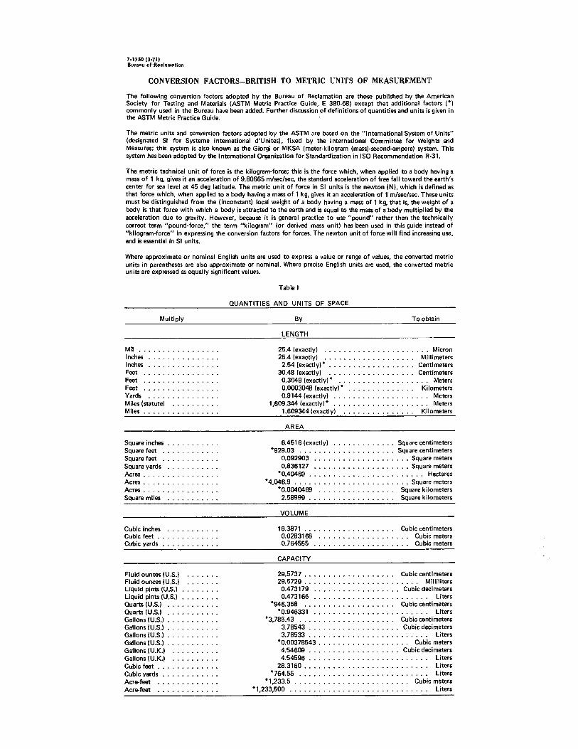
CONVERSION FACTORS-BRITISH TO METRIC UNITS OF MEASUREMENT
The following conversion factors adopted by the Bureau of Reclamation are those published by the American Society for Testing and Materials (ASTM Metric Practice Guide, E 380-68) except that additional factors (*) commonly used in the Bureau have been added. Further discussion of definitions of quantities and units is given in the ASTM Metric Practice Guide.
The metric units and conversion factors adopted by the ASTM are based on the "International System of Units" (designated SI for Systeme International d'Unites), fixed by the International Committee for Weights and Measures; this system is also known as the Giorgi or MKSA (meter-kilogram (mass)-second-ampere) system. This system has been adopted by the International Organization for Standardization in ISO Recommendation R-31.
The metric technical unit of force is the kilogram-force; this is the force which, when applied to a body having a mass of 1 kg, gives it an acceleration of 9.80665 m/sec/sec, the standard acceleration of free fall toward the earth's center for sea level at 45 deg latitude. The metric unit of force in SI units is the newton (N), which is defined as that force which, when applied to a body having a mass of 1 kg, gives it an acceleration of 1 m/sec/sec. These units must be distinguished from the ( inconstant) local weight of a body having a mass of 1 kg, that is, the weight of a body is that force with which a body is attracted to the earth and is equal to the mass of a body multiplied by the acceleration due to gravity. However, because it is general practice to use "pound" rather than the technically correct term "pound-force," the term "kilogram" (or derived mass unit) has been used in this guide instead of "kilogram-force" in expressing the conversion factors for forces. The newton unit of force will find increasing use, and is essential in SI units.
Where approximate or nominal English units are used to express a value or range of values, the converted metric units in parentheses are also approximate or nominal. Where precise English units are used, the converted metric units are expressed as equally significant values.
Multiply
Mil ......... . Inches ....... . Inches . Feet Feet ........ . Feet ........ . Yards .............. . Miles (statute) ...... . Miles ............... .
Square inches .......... . Square feet . . . . . . . . . . . . Square feet . . . . . . . . . . . . Square yards . . . . . . . Acres .... . Acres .... . Acres .... . Square miles ....
Cubic inches . . . . . . . ... . Cubic feet ............ . Cubic yards . . . . . . . . . . . .
Fluid ounces (U.S.) ...... . Fluid ounces (U.S.) ...... . Liquid pints (U.S.) ....... . Liquid pints (U.S.) ....... . Quarts (U.S.) . . . . . . . Quarts (U.S.) ...... . Gallons (U.S.) .......... . Gallons (U.S.) .......... . Gallons (U.S.) .......... . Gallons (U.S.) .......... . Gallons (U.K.) ......... . Gallons (U.K.) ......... . Cubic feet ............ . Cubic yards . . . . . . ..... . Acre-feet ............ . Acre-feet ............ .
Table I
QUANTITIES AND UNITS OF SPACE
By To obtain
LENGTH
25.4 (exactly) . . . . . . . . . . . . . . . . . Micron 25.4 (exactly) . . . . . . . . . . . . . . Millimeters
2.54 (exactly)* . . . . . . . . . . . . . . . . . . Centimeters 30.48 (exactly) . . . . . . . . . . . . . . Centimeters
0.3048 (exactly)* . . . . . . . . . . . . . . . . . . . Meters 0.0003048 (exactly)* . . . . . . . . . . . . . . Kilometers 0.9144 (exactly) . . . . . . . . . . . . . . . . . . . . Meters
1,609.344 (exactly)* . . . . . . . . . . . . . . . . . . . . Meters 1.609344 (exactly) . . . . . . . . . . . . . . . Kilometers
AREA
6.4516 (exactly) ............. Square centimeters *929.03 . . . . . . . . . . . . . . . . . . . . Square centimeters
0.092903 .................... Square meters 0.836127 . . . . . . . . . . . . . . . . . . Square meters
•0.40459 . . . . . . . . . . . . . . . . . . . . . . . . Hectares * 4,046.9 ........................ Square meters
*0.0040469 . . . . . . . . . . . . . Square kilometers 2.58999 . . . . . . . . . . . . . Square kilometers
VOLUME
16.3871 ............ . 0.0283168 ............ . 0.764555 ............. .
CAPACITY
. Cubic centimeters Cubic meters
. . . . Cubic meters
29.5737 . . . . . . . . . . . . . . . . . . . Cubic centimeters 29.5729 . . . . . . . . . . . . . . . . . . . . . . . . Milliliters
0.473179 .................. Cubic decimeters 0.473166 . . . . . . . . . . . . . . . . . . . . . . Liters
*946.358 . . . . . . . . . . . . . . . . . Cubic centimeters *0.946331 . . . . . . . . . . . . . . . . . . . . . . Liters
*3,785.43 . . . . . . . . . . . . . . . . . . Cubic centimeters 3. 78543 . . . . . . . . . . . . . . . . . Cubic decimeters 3. 78533 . . . . . . . . . . . . . . . . . . . . . . . Liters
*0.00378543 . . . . . . . . . . . . . . . . . . . Cubic meters 4.54609 . . . . . . . . . . . . . . . . . . . Cubic decimeters 4. 54596 . . . . . . . . . . . . . . . . . . . . . . . . . Liters
28.3160 . . . . . . . . . . . . . . . . . . . . . . . . . . Liters *764.55 . . . . . . . . . . . . . . . . . . . . . . . . . . . Liters
* 1,233.5 . . . . . . . . . . . . . . . . . . . . . . . . Cubic meters * 1,233,500 . . . . . . . . . . . . . . . . . . . . . . . . . . . . . Liters
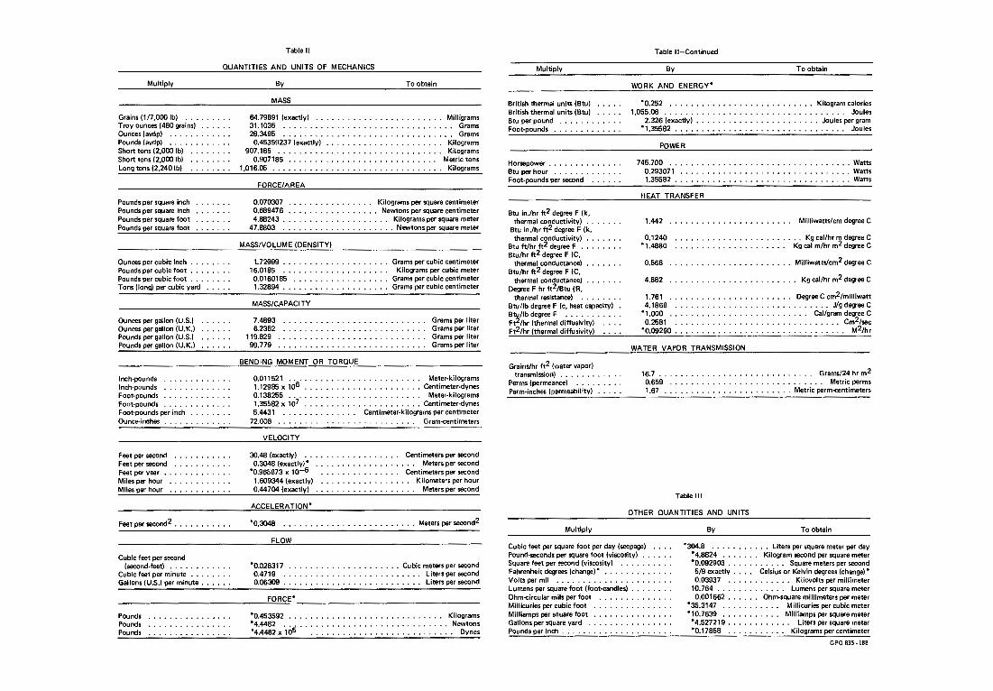
Table 11
QUANTITIES AND UNITS OF MECHANICS
Multiply
Grains ( 1 /7,000 lb) ..•..•... Troy ounces (480 grains) ..... . Ounces (avdp) ........... . Pounds (avdp) ........ . Short tons (2,000 lb) ....... . Short tons (2,000 lb) ....... . Long tons (2,240 lb) ...•....
Pounds per square inch Pounds per square inch Pounds per square foot Pounds per square foot
Ounces per cubic inch ... . Pounds per cubic foot .. . Pounds per cubic foot ....... . Tons (long) per cubic yard .... .
Ounces per gallon (U.S.) Ounces per gallon (U.K.) Pounds per gallon (U.S.) Pounds per gallon (U.K.)
Inch-pounds .•......... , . Inch-pounds Foot-pounds ............ . Foot-pounds ............ . Foot-pounds per inch .•.... Ounce-inches ............ .
Feet per second . . . . Feet per second . . . . Feet per year • • . . . . Miles per hour Miles per hour ...•.....
Feet per second2 ..• , . , ....•
Cubic feet per second (second-feet) . , .. ,
Cubic feet per minute . Gallons (U.S.) per minute ..... .
Pounds Pounds Pounds
By
MASS
64.79891 (exactly) 31.1035 .•...... 28.3495 ....... .
0.45359237 (exactly) 907.185 ........ .
0.907185 ...... . 1,016.05 ....•.....
FORCE/AREA
To obtain
......••.......... Milligrams
. ................... Grams . ............ Grams
.............•........ Kilograms . ...•.......... Kilograms
. . , . . Metric tons . .••........... Kilograms
0.070307 • . . . . . . . . • . . . . . . Kilograms per square centimeter 0.689476 •••.....•.•...... Newtons per square centimeter 4.88243 . . . . . . . . . . . . . . . . . . . . Kilograms per square meter
47,8803 . . . . . . . . . . . . . ... Newtons per square meter
MASS/VOLUME (DENSITY)
U:!999 ................... . 16.0185 .................. . 0.0160185 ................. . 1.32894 ...•.....••.......•.
MASS/CAPACITY
Grams per cubic centimeter Kilograms per cubic meter
Grams per cubic centimeter Grams per cubic centimeter
7.4893 .......................... . Grams per I iter Grams per liter Grams per liter Grams per liter
6.2362 ..••....•...............•.. 119.829 ...........••............ 99.779 ........................... .
BENDING MOMENT OR TORQUE
0.011521 . • . . . . . • . . . . . • . • . . . . . . . . . Meter-kilograms 1. 12985 x ,06 . . . . . . . . . • . • . . . • . • . . . . Centimeter-dynes 0.138255 . . . . . . . . . . . . . . . . . . . . • . . . . Meter-kilograms 1.35582 x 10⁷ . . . . . ......... Centimeter-dynes 5.4431 • • • . . . . . Centimeter-kilograms per centimeter
72.008 .... , . . . . . . . . . . . . . . . . . . . . . Gram-centimeters
VELOCITY
30.48 (exactly) . . . . . . . . . . . . . . . • . . Centimeters per second 0,3048 (exactly)• . . . • . • . . . . . • . . . . . . . Meters per second
*0.965873 x 10'-6 . . . . • . . . . . . . . . . Centimeters per second 1,609344 (exactly) . . . . . . • . . . . . . . . . . Kilometers per hour 0.44704 (exactly) ... , . . . . . . . . . . • . . . . Meters per second
ACCELERATION*
*0.3048 .•. . Meters per second2
FL W
*0.028317 ....• , ............... Cubic meters per second 0.4719 . . . . . . . . . . . . . . . . . . . . . . . . Liters per second 0.06309 . . . . . . . . • • • . . . . . . . . . . . . . . • Liters per second
FORCE*
*0.453592 .. *4.4482 •.. *4.4482 X 10⁵
. . . . . . . . . . . . . . . . . . . . . . Kilograms
. . . . . . . . . . . . . . . . . , ..... Newtons
. .. • . .. . . . .. . .. . .. .. .. . , Dynes
Multiply
British thermal units (Btu) .... . British thenmal units (Btu) .... . Btu per pound . . . Foot-pounds ............ .
Horsepower . . . . . . . . . , . . . . Btu per hour . . . . . . . . Foot-pounds per second ..... .
Btu in./hr tt2 degree F (k, thermal conductivity) ..
Btu in./hr tt2 degree F (k, thermal conductivity)
Btu ft/hr tt2 degree F . Btu/hr tt2 degree F (C,
thermal conductance) Btu/hr tt2 degree F (C,
thermal conductance) Degree F hr tt2/Btu ( R,
thermal resistance) ...... , , Btu/lb degree F {c, heat capacity) . Btu/lb degree F .•......... Ft2/hr (thermal diffusivity) Ft2/hr (thermal diffusivity)
Grains/hr tt2 (water vapor) transmission} ......... .
Perms (permeance) ... , •.... Perm-inches (permeability) .....
Multiply
Table II-Continued
By To obtain
WORK AND ENERGY*
*0.252 ...............•......•.... Kilogram calories 1,055.06 . . . • • . . . . . . • • . . . . . . . . . . . . • . . • . . . . . Joules
2.326 (exactly) ........•...••......••• Joules per gram • 1 .35582 . . . . . . . . . . . • . . . . . . . . . . . . . . . . . . . . Joules
POWER
745. 700 ........•..•.....•.•.....•.......• Watts 0.293071 . . . ................. Watts 1.35582 . . . . .............••.. Watts
HEAT TRANSFER
1.442 ............•••. Milliwatts/cm degree C
0.1240 . . • . . . . . . . • . • . . . . . Kg cal/hr m degree C • 1 .4880 . . . . . . . . . . . . . . . . . . . . . Kg cal m/hr m2 degree C
0.568 ............•.......•.. Milliwatts/cm2 degree C
4.882 . . . . • • . . . . . . . . • • . . . . Kg cal/hr m2 degree C
1.761 ..............•.... Degree C cm2/milliwatt 4.1868 ..............•.............. Jig degree C
• 1,000 . . . . . . . . . . . . . . • . . . . . . . . . . . Cal/gram degree C 0.2581 •.•.....•.•....•.•............ , Cm2/sec
*0.09290 . . . . . . . • • . . . . . . . . . . . . . . . . . . . . . . • M2/hr
WATER VAPOR TRANSMISSION
16.7 ....••... , • . . . . . . . . . • • . . . . . . . Grams/24 hr m2 0.659 .•........•......•... , ...... , Metric penms 1.67 . , ....•...... , .. , ....... Metric perm-centimeters
Table Ill
OTHER QUANTITIES AND UNITS
By To obtain
Cubic feet per square foot per day (seepage) Pound-seconds per square foot (viscosity) •.....
*304.8 • . • • • Liters per square meter per day • 4.8824 • . . . . . . Kilogram second persquare meter *0.092903 . • . . . . • . . . . Square meters per second 5/9 exactly . . . . Celsius or Kelvin degrees (change)•
Square feet per second {viscosity) ......... . Fahrenheit degrees (change)* ..•......•... Volts per mil .........•............ Lumens per square foot (foot-candles) ••.....• Ohm-circular mils per foot .... , ........ . Millicurles per cubic foot ........ . Mil liamps persquare foot .............. . Gallons persquare yard . . . . . . . . , . . . . • • . Pounds per inch ............•........
0.03937 ........ , . , . Kilovolts per millimeter 10.764 . . . . . . . • • • . . . Lumens per square meter 0.001662 . . . . . . Ohm-square millimeters per meter
*35.3147 . . . . . . . . . . . Millicuries per cubic meter •10.7639 . . . . . . . . . . . Milliamps per square meter
• 4.527219 . . . . . . . . . . . . Liters per square meter *0.17858 . . . . . • . • . . . Kilograms per centimeter
GPO 835-188

•••••••••••••••••••••••••••••••••• e e ••••• e ••• e ••• e e •••••••••••••••••••• e e • • • • • • • • • • • ................................................ I •••••••••••••••••••••••••• e •••••••
ABSTRACT
Laboratory experiments, using a simplified air model, were conducted to obtain the correlation between draft tube shape and the draft tube surge characteristics-the range of occurrence, frequencies, and pressure amplitudes of the surges. Dimensionless parameters were used to compare results. The draft tube shape was found to have significant influence on the surging characteristics. Surge measurements obtained from two hydraulic turbine model studies are also compared using the dimensionless parameters. Hydraulic and air model studies of the same draft tube produced satisfactory correlation. The information presented can be used to predict the surge characteristics of prototype and model turbines, or as an aid in draft tube design where surge reduction or resonance minimization are considered as design criteria. Examples are included to illustrate application of the laboratory results.
----·················································· .. -· ................................ --.
ABSTRACT
Laboratory experiments, using a simplified air model, were conducted to obtain the correlation between draft tube shape and the draft tube surge characteristics-the range of occurrence, frequencies, and pressure amplitudes of the surges. Dimensionless parameters were used to compare results. The draft tube shape was found to have significant influence on the surging characteristics. Surge measurements obtained from two hydraulic turbine model studies are also compared using the dimensionless parameters, Hydraulic and air model studies of the same draft tube produced satisfactory correlation. The information presented can be used to predict the surge characteristics of prototype and model turbines, or as an aid in draft tube design where surge reduction or resonance minimization are considered as design criteria. Examples are included to illustrate application of the laboratory results.
····················································································
ABSTRACT
Laboratory experiments, using a simplified air model, were conducted to obtain the correlation between draft tube shape and the draft tube surge characteristics-the range of occurrence, frequencies, and pressure amplitudes of the surges,,Dimensionless parameters were used to compare results. The draft tube shape was found to have significant influence on the surging characteristics. Surge measurements obtained from two hydraulic turbine model studies are also compared using the dimensionless parameters. Hydraulic and air model studies of the same draft tube produced satisfactory correlation. The information presented can be used to predict the surge characteristics of prototype and model turbines, or as an aid in draft tube design where surge reduction or resonance minimization are considered as design criteria. Examples are included to illustrate application of the laboratory results.

REC-ERC-72-24 Palde,U J INFLUENCE OF DRAFT TUBE SHAPE ON SURGING CHARACTERISTICS OF REACTION TURBINES Bur Reclam Rep REC-ERC-72-24, Div Gen Res, September 1972. Bureau of Reclamation, Denver, 29 p, 22 fig, 2 tab, 5 ref, append
DESCRIPTORS-/ *draft tubes/ turbines/ *surges/ *hydroelectric powerplants/ hydraulic machinery/ fluid mechanics/ dimensional analysis/ model tests/ fluid flow/ pressure/ frequency/ *shape/ resonance/ test results/ hydraulic design/ *reaction turbines/ hydraulic turbines/ noise (sound)/ hydraulic models/ vibration/ wicket gates/ hydraulic similitude IDENTIFIERS-/ hydraulic pressure tests/ Fontenelle Dam, Wyo/ Grand Coulee Powerplant, Wash/ water pressure tests
REC-ERC-72-24 Palde, U J INFLUENCE OF DRAFT TUBE SHAPE ON SURGING CHARACTERISTICS OF REACTION TURBINES Bur Reclam Rep REC-ERC-72-24, Div Gen Res, September 1972. Bureau of Reclamation, Denver, 29 p, 22 fig, 2 tab, 5 ref, append
DESCRIPTORS-/ *draft tubes/ turbines/ *surges/ *hydroelectric powerplants/ hydraulic machinery/ fluid mechanics/ dimensional analysis/ model tests/ fluid flow/ pressure/ frequency/ *shape/ resonance/ test results/ hydraulic design/ *reaction turbines/ hydraulic turbines/ noise (sound)/ hydraulic models/ vibration/ wicket gates/ hydraulic similitude IDENTIFIERS-/ hydraulic pressure tests/ Fontenelle Dam, Wyo/ Grand Coulee Powerplant, Wash/ water pressure tests
