rebco tapes with high normal zone propagation velocity: an
TRANSCRIPT
REBCO tapes with high normal zone propagation velocity: an avenue for faster quench detection/protection systems in
REBCO magnets?
1
Christian Lacroix and Frédéric SiroisLaboratory of Superconductivity and Magnetism (LSM)
Polytechnique Montréal, Canada
US MDP REBCO WG Meeting, OCTOBER 7TH 2021
C. Lacroix and F. Sirois, US MDP REBCO WG Meeting, Oct. 7th, 2021 (contact: [email protected])

Polytechnique Montréal, Canada
2
Leading Canadian engineering institution in education and research-French-speaking, nearly 150 years old!-Active in all areas of engineering + many fields in pure and applied sciences
C. Lacroix and F. Sirois, US MDP REBCO WG Meeting, Oct. 7th, 2021 (contact: [email protected])
GRADUATES SINCE 1873 59,600
STUDENTSOver
9,000
DEGREES AWARDED IN 2018-2019
1,706
PROFESSORS278
ANNUAL BUDGET$260 M
Laboratory of Superconductivity and Magnetism (LSM)
3
- Founded in 2020 to synergize these two activities through- shared personnel- common projects- common equipment and computer infrastructure
- magnets, test benches, instruments, computation servers, etc.
- Associated with the microfabrication lab, which includes- thin film deposition facilities (sputtering, electrodeposition, etc.)- characterization facilities for properties of material
- electric & magnetic, tribo-mechanical, chemical, structural, etc.- all types of microscopy (SEM, TEM, XPS, …)
C. Lacroix and F. Sirois, US MDP REBCO WG Meeting, Oct. 7th, 2021 (contact: [email protected])

Current focus in applied superconductivity
4
- Development of advanced numerical modeling tool for HTS tapes- Electromagnetic + thermal problems = quench simulation
- Advanced characterization of HTS tape properties- Electric properties + quench behavior
- Innovative HTS tape architectures and impact on NZPV → Today’s topic- Past focus → fault current limiters- New focus →magnets
C. Lacroix and F. Sirois, US MDP REBCO WG Meeting, Oct. 7th, 2021 (contact: [email protected])
Acknowledgements for today’s presentation
5
Polytechnique Montréal (LSM)- Dr. Jean-Hughes Fournier-Lupien (Post-doc)- Haifa Ben Saad (PhD student)- Jaël Giguère (Master’s student)- Yannick Lapierre (intern)
Institute of Ciencia de Materiales de Barcelona (ICMAB, Barcelona, Spain)- Pedro Barusco (PhD student)- Prof. Xavier Obradors- Prof. Xavier Granados
C. Lacroix and F. Sirois, US MDP REBCO WG Meeting, Oct. 7th, 2021 (contact: [email protected])
Increasing quench velocity in 2G HTS CC
6
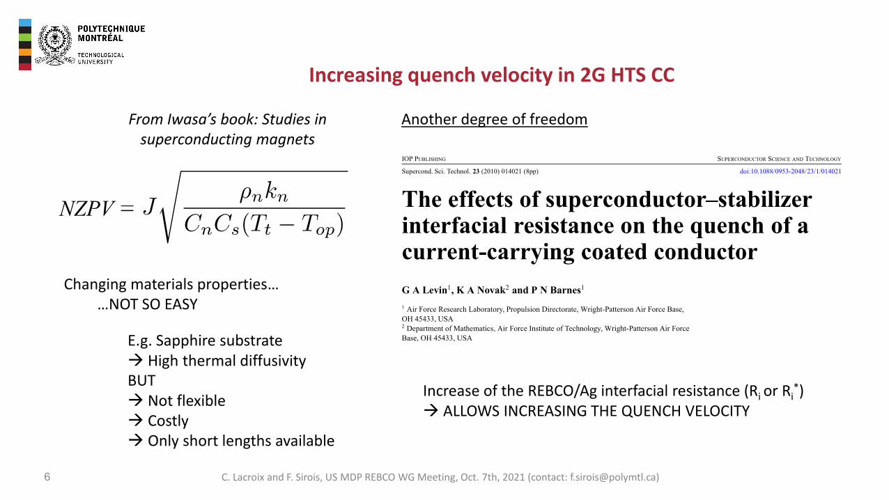
From Iwasa’s book: Studies in superconducting magnets
Changing materials properties……NOT SO EASY
E.g. Sapphire substrate→ High thermal diffusivityBUT→ Not flexible→ Costly→ Only short lengths available
IOP PUBLISHING SUPERCONDUCTOR SCIENCE AND TECHNOLOGY
Supercond. Sci. Technol. 23 (2010) 014021 (8pp) doi:10.1088/0953-2048/23/1/014021
The effects of superconductor–stabilizerinterfacial resistance on the quench of acurrent-carrying coated conductorG A Levin1, K A Novak2 and P N Barnes1
1 Air Force Research Laboratory, Propulsion Directorate, Wright-Patterson Air Force Base,OH 45433, USA2 Department of Mathematics, Air Force Institute of Technology, Wright-Patterson Air ForceBase, OH 45433, USA
Received 1 August 2009, in final form 15 September 2009Published 9 December 2009Online at stacks.iop.org/SUST/23/014021
AbstractWe present the results of numerical analysis of a model of normal zone propagation in coatedconductors. The main emphasis is on the effects of increased contact resistance between thesuperconducting film and the stabilizer on the speed of normal zone propagation, the maximumtemperature rise inside the normal zone, and the stability margins. We show that with increasingcontact resistance the speed of normal zone propagation increases, the maximum temperatureinside the normal zone decreases, and stability margins shrink. This may have an overallbeneficial effect on quench protection quality of coated conductors. We also briefly discuss thepropagation of solitons and development of the temperature modulation along the wire.
(Some figures in this article are in colour only in the electronic version)
1. Introduction
Quench protection of large scale devices, such as magnets andcables, based on coated conductors has emerged as one of themajor unresolved obstacles in their implementation. High op-erating temperature and, correspondingly, relatively large heatcapacity make coated conductors very stable in comparison tothe conventional low temperature superconductors. However,the side effect of this positive quality is that when a normalzone does nucleate it expands very slowly. The potential dropacross a short normal section of a long conductor is difficult todetect and in adiabatic or nearly adiabatic conditions the tem-perature of this section may rise above the safe limit resultingin irreversible damage to the whole coil or cable strand.
This paper presents the results of a numerical analysisof a model of normal zone propagation (NZP) specializedto the architecture of the state-of-the-art coated conductors.Its main purpose is to elucidate the effects of the interfacialresistance (contact resistance) between the superconductingYBa2Cu3O7−x (YBCO) film and copper stabilizer on stabilityand speed of NZP. The interest to this problem arose initiallyfrom an effort to understand some peculiar effects thataccompany quench in coated conductors [1, 2]. It seemsclear now that these phenomena result from a large resistance
between the YBCO film and a metal substrate [3, 4]. Thisunderstanding has lead to realization that increasing the contactresistance between the YBCO film and copper stabilizermay have beneficial effect on the speed of the normal zonepropagation [5–7].
The effects of a large contact resistance between thestabilizer and conventional low Tc superconductors have beenstudied extensively in the past [8–12]. However, the ideaof tailoring the properties of the superconducting wires byincreasing the contact resistance has not been adopted towider use. This option of conductor design had lain dormantfor many years—a solution in wait of a problem. Perhaps,coated conductors present just such a problem. Increasingthe contact resistance does make the conductor less stable.However, since coated conductors are inherently much morestable than the low Tc superconductors, the reduction of thestability margins accompanied by increasing the speed of NZPmay allow to develop coated conductors overall better suitedfor large scale applications than their current version with aminimized contact resistance.
Here we will discuss the NZP in a straight coatedconductor cooled from the surface. This model more closelydescribes the typical conditions in the experiments suchas [1, 2] or in a superconducting cable, rather than in a pancake
0953-2048/10/014021+08$30.00 © 2010 IOP Publishing Ltd Printed in the UK1
Another degree of freedom
Increase of the REBCO/Ag interfacial resistance (Ri or Ri*)
→ ALLOWS INCREASING THE QUENCH VELOCITY
NZPV
C. Lacroix and F. Sirois, US MDP REBCO WG Meeting, Oct. 7th, 2021 (contact: [email protected])

Characteristic lengths
7
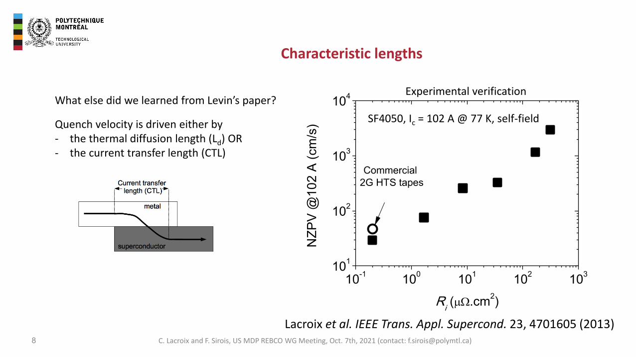
Quench velocity is driven either by- the thermal diffusion length (Ld) OR- the current transfer length (CTL)
What else did we learned from Levin’s paper?F. Roy’s thesis, 2010, EPFL
Ld dominates
CTL dominates
Numerical simulations
C. Lacroix and F. Sirois, US MDP REBCO WG Meeting, Oct. 7th, 2021 (contact: [email protected])
8
Quench velocity is driven either by- the thermal diffusion length (Ld) OR- the current transfer length (CTL)
What else did we learned from Levin’s paper?Experimental verification
SF4050, Ic = 102 A @ 77 K, self-field
Lacroix et al. IEEE Trans. Appl. Supercond. 23, 4701605 (2013)C. Lacroix and F. Sirois, US MDP REBCO WG Meeting, Oct. 7th, 2021 (contact: [email protected])
Characteristic lengths

Current flow diverter (CFD) concept
9
From a practical point of view…increasing the REBCO/Ag interfacial resistance may lead to premature quench at current lead contacts, which is highly undesirable
Can we increase the CTL without increasing Ri too much?
YES, with the Current Flow Diverter (CFD) concept
How?
Goal: force the current to pass through a specific path
(leads to current crowding) Lacroix et al. SUST 27, 035003 (2014)US Patent: Lacroix et al. US9029296B2
By using a resistive layer that partially covers the Ag/HTS interface
C. Lacroix and F. Sirois, US MDP REBCO WG Meeting, Oct. 7th, 2021 (contact: [email protected])

Current flow diverter (CFD) concept
10
How?
Fournier-Lupien et al. SUST 34, 085001 (2021)
Current crowding induces a normal zone with a U-shape that further increases the CTL (dynamic CTL vs static CTL)
static CTL = f(Ri)
dynamic CTL = f(Ri,Tprofile) > static CTL
From a practical point of view…increasing the REBCO/Ag interfacial resistance may lead to premature quench at current lead contacts, which is highly undesirable
Can we increase the CTL without increasing Ri too much?
YES, with the Current Flow Diverter (CFD) concept
Goal: force the current to pass through a specific path
(leads to current crowding)
C. Lacroix and F. Sirois, US MDP REBCO WG Meeting, Oct. 7th, 2021 (contact: [email protected])

Current flow diverter (CFD) concept
11
From a practical point of view…increasing the REBCO/Ag interfacial resistance may lead to premature quench at current lead contacts, which is highly undesirable
How?
Fournier-Lupien et al. SUST 31, 125019 (2018)
Current crowding induces a normal zone with a U-shape that further increases the CTL → dynamic CTL
Can we increase the CTL without increasing Ri too much?
YES, with the Current Flow Diverter (CFD) concept
Goal: force the current to pass through a specific path
(leads to current crowding)
C. Lacroix and F. Sirois, US MDP REBCO WG Meeting, Oct. 7th, 2021 (contact: [email protected])
Current flow diverter (CFD) concept
12
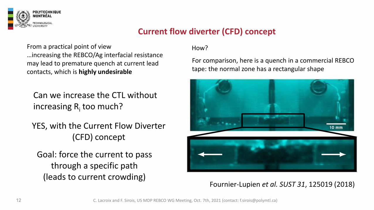
From a practical point of view…increasing the REBCO/Ag interfacial resistance may lead to premature quench at current lead contacts, which is highly undesirable
How?
Fournier-Lupien et al. SUST 31, 125019 (2018)
For comparison, here is a quench in a commercial REBCO tape: the normal zone has a rectangular shape
Can we increase the CTL without increasing Ri too much?
YES, with the Current Flow Diverter (CFD) concept
Goal: force the current to pass through a specific path
(leads to current crowding)
C. Lacroix and F. Sirois, US MDP REBCO WG Meeting, Oct. 7th, 2021 (contact: [email protected])
Current flow diverter (CFD) concept
13
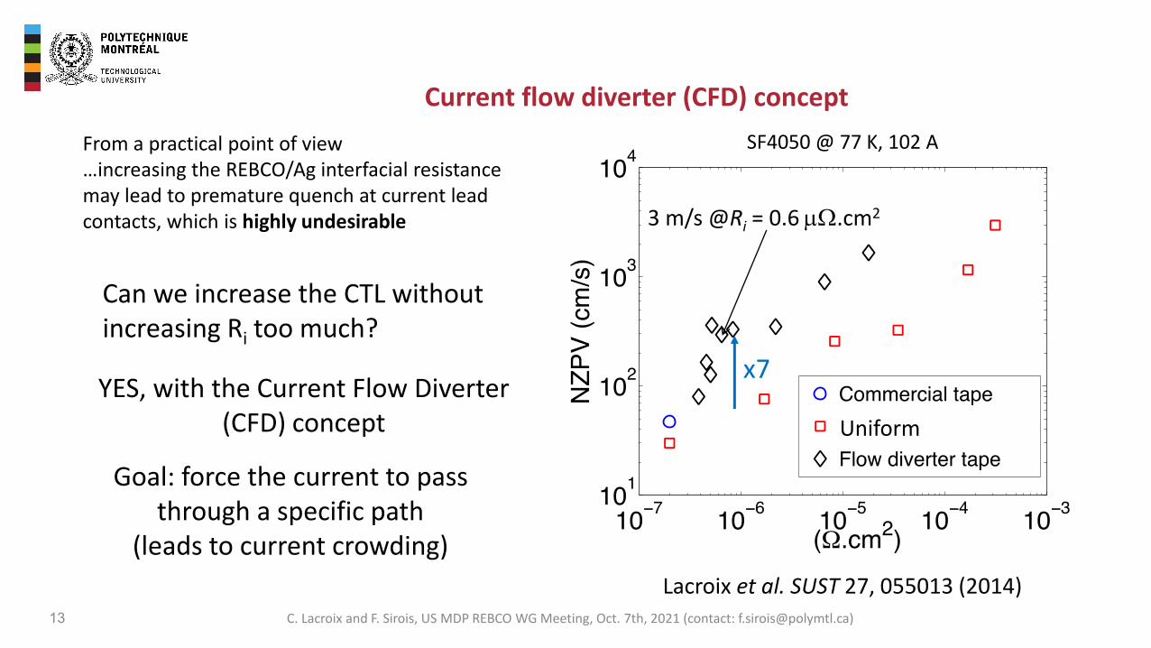
From a practical point of view…increasing the REBCO/Ag interfacial resistance may lead to premature quench at current lead contacts, which is highly undesirable
1
3 m/s @Ri = 0.6 mW.cm2
Uniform
SF4050 @ 77 K, 102 A
Lacroix et al. SUST 27, 055013 (2014)
x7
Can we increase the CTL without increasing Ri too much?
YES, with the Current Flow Diverter (CFD) concept
Goal: force the current to pass through a specific path
(leads to current crowding)
C. Lacroix and F. Sirois, US MDP REBCO WG Meeting, Oct. 7th, 2021 (contact: [email protected])
Alternative CFD architectures
14
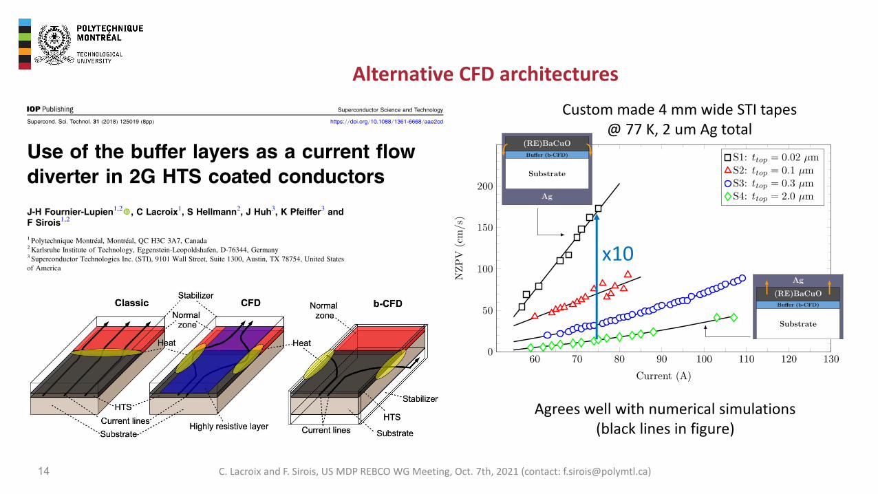
Agrees well with numerical simulations (black lines in figure)
Custom made 4 mm wide STI tapes @ 77 K, 2 um Ag total
x10
C. Lacroix and F. Sirois, US MDP REBCO WG Meeting, Oct. 7th, 2021 (contact: [email protected])
Alternative CFD architectures
15
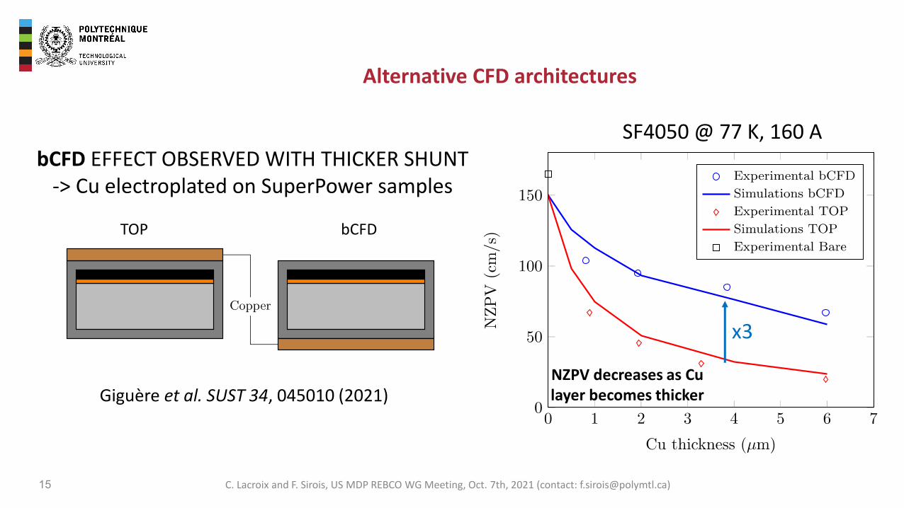
SF4050 @ 77 K, 160 AbCFD EFFECT OBSERVED WITH THICKER SHUNT
-> Cu electroplated on SuperPower samples
TOP bCFD
Giguère et al. SUST 34, 045010 (2021)NZPV decreases as Cu layer becomes thicker
x3
C. Lacroix and F. Sirois, US MDP REBCO WG Meeting, Oct. 7th, 2021 (contact: [email protected])
Alternative CFD architectures
16
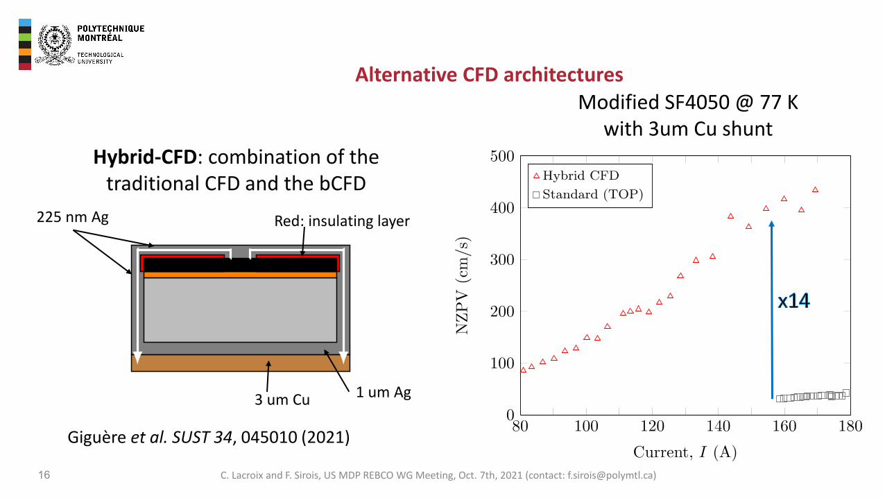
Modified SF4050 @ 77 Kwith 3um Cu shunt
Hybrid-CFD: combination of the traditional CFD and the bCFD
Giguère et al. SUST 34, 045010 (2021)
225 nm Ag
1 um Ag3 um Cu
Red: insulating layer
C. Lacroix and F. Sirois, US MDP REBCO WG Meeting, Oct. 7th, 2021 (contact: [email protected])
Manufacturing of long CFD REBCO tapes
17
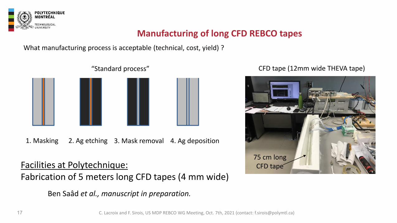
What manufacturing process is acceptable (technical, cost, yield) ?
“Standard process”
Ben Saâd et al., manuscript in preparation.
75 cm longCFD tape
Revue de littérature
15
d‟une couche mince d‟argent possèdent une résistance d‟interface Supraconductrice-métal
plus élevée que les régions masquées, d‟où la création du concept CFD. [27, 28].
Figure III- 7: les différentes étapes de la microfabrication de l’architecture CFD classique.
3.6 Application des rubans SHTc dans les électro-aimants
Les fils supraconducteurs sont exploités pour la génération de fort champ magnétique dans
des applications comme l‟imagerie à résonance magnétique (IRM), la résonance magnétique
nucléaire (RMN) et les accélérateurs des particules. En effet, les électro-aimants
supraconducteurs sont construits des fils SBTc bobinés et refroidis par l‟hélium liquide. La
figure III-8 représente une vue en coupe d‟un électro-aimant supraconducteur.
1. Masking 2. Ag etching 3. Mask removal 4. Ag deposition
Facilities at Polytechnique: Fabrication of 5 meters long CFD tapes (4 mm wide)
CFD tape (12mm wide THEVA tape)
C. Lacroix and F. Sirois, US MDP REBCO WG Meeting, Oct. 7th, 2021 (contact: [email protected])
100
1000
10000
100000
400 500 600 700 800
NZP
V (c
m/s
) @ 7
7K
Applied current (A)
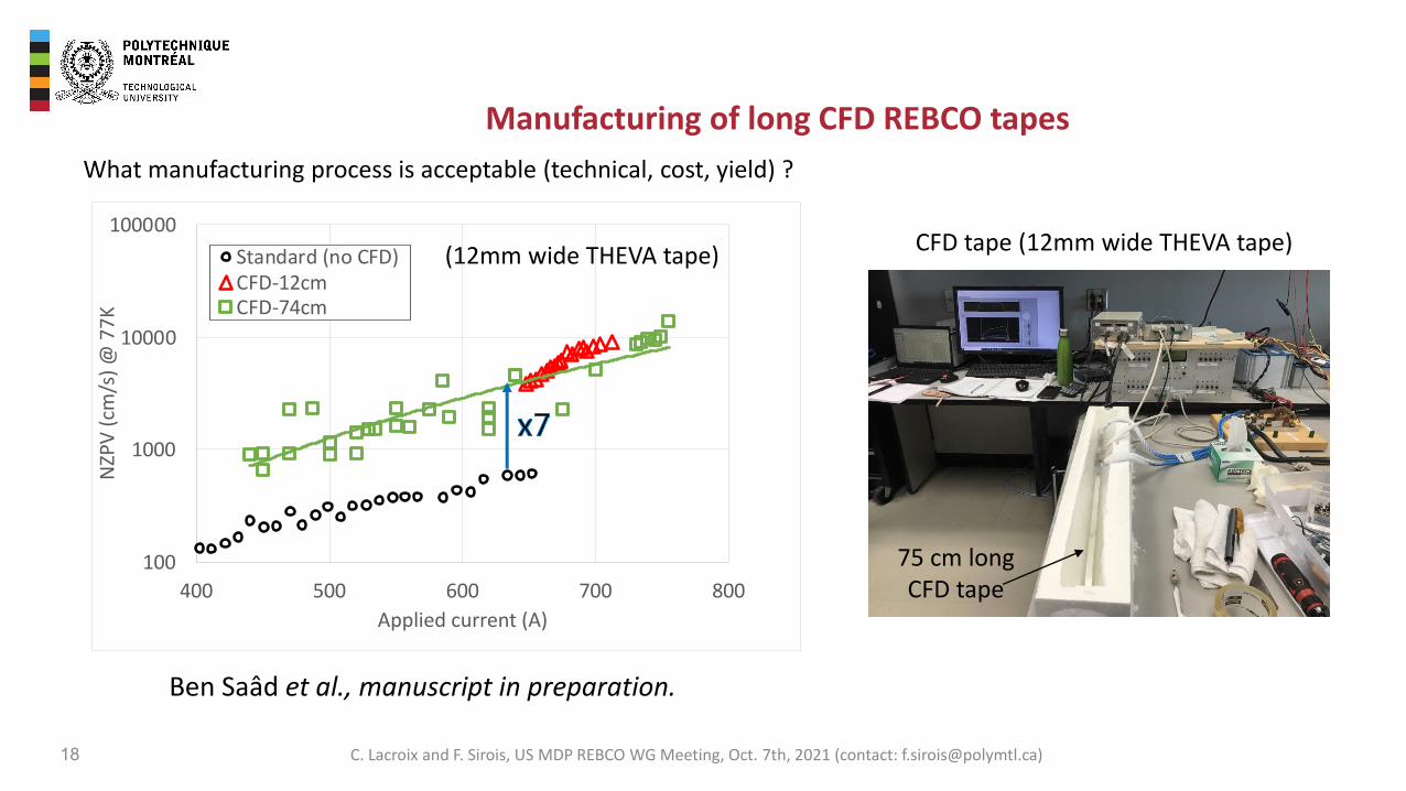
Standard (no CFD)CFD-12cmCFD-74cm
Manufacturing of long CFD REBCO tapes
18
What manufacturing process is acceptable (technical, cost, yield) ?
Ben Saâd et al., manuscript in preparation.
75 cm longCFD tape
(12mm wide THEVA tape) CFD tape (12mm wide THEVA tape)
C. Lacroix and F. Sirois, US MDP REBCO WG Meeting, Oct. 7th, 2021 (contact: [email protected])
Manufacturing of long CFD REBCO tapes
19
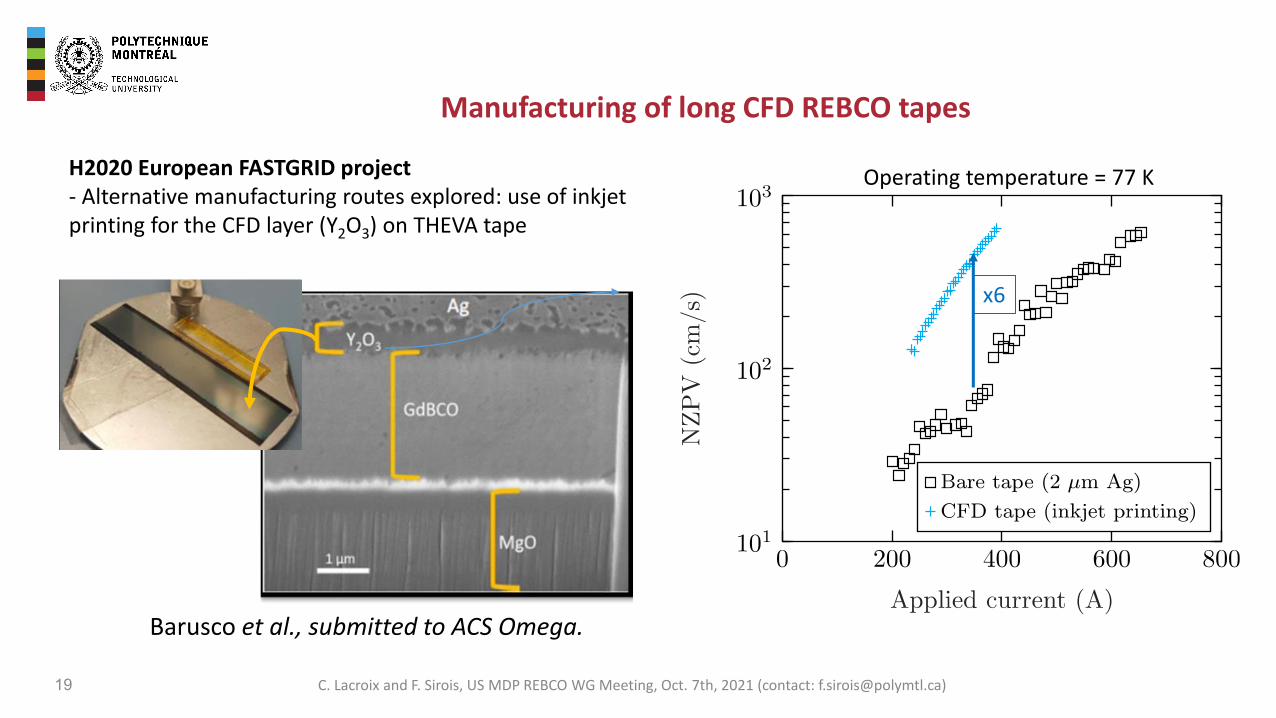
H2020 European FASTGRID project- Alternative manufacturing routes explored: use of inkjet printing for the CFD layer (Y2O3) on THEVA tape
9
3 Results
The CFD-CC after yttria deposition and silver sputtering is shown in Figure 1(a) and (b) respectively
and the multilayered architecture can be clearly seen in the SEM-FIB cross section (Figure 1(c)) of
the CC after the CSD process and silver coating. The yttria deposition by CSD was performed at two
different stages of the CC manufacturing process to analyze its suitability to generate CCs with the
CFD effect.
Figure 1: (a) Picture of GdBCO CC after IJP of yttria and pyrolysis at 450 °C. The sample is mounted on a metal plate for
silver sputtering. (b) Picture of GdBCO CC after silver sputtering. (c) SEM-FIB cross-section of a THEVA CFD-CC deposited
with yttria using ink jet printing.
In the first route, the CC is neither oxygenated nor silver-coated prior to the yttria’s deposition. The
sequence of experimental steps used for the first yttria-CFD route is illustrated in Figure 2. In step 1,
83% of the tape’s width (12 mm) is deposited with an yttrium propionate solution via CSD (IJP or
spin coating) and pyrolysed at 450 °C for 1 hour to achieve an amorphous yttria layer (see details in
section 2). In step 2, the tape is silver-coated by sputtering (500-1000 nm). Finally, in step 3, the
tape is annealed in 1 bar of oxygen atmosphere to load the necessary oxygen content into the
GdBCO film to enable its superconducting properties (Figure S4).
1 2 3 4 5 6 7 8 9 10 11 12 13 14 15 16 17 18 19 20 21 22 23 24 25 26 27 28 29 30 31 32 33 34 35 36 37 38 39 40 41 42 43 44 45 46 47 48 49 50 51 52 53 54 55 56 57 58 59 60 61 62 63 64 65
Barusco et al., submitted to ACS Omega.
x6
Operating temperature = 77 K
C. Lacroix and F. Sirois, US MDP REBCO WG Meeting, Oct. 7th, 2021 (contact: [email protected])
Application: high NZPV tapes for magnets
20
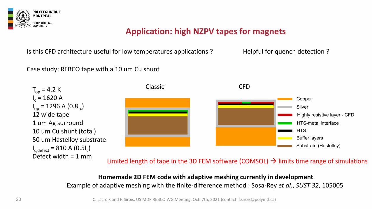
Top = 4.2 KIc = 1620 AIop = 1296 A (0.8Ic)12 wide tape1 um Ag surround10 um Cu shunt (total)50 um Hastelloy substrateIc,defect = 810 A (0.5Ic)Defect width = 1 mm
Is this CFD architecture useful for low temperatures applications ?
Case study: REBCO tape with a 10 um Cu shunt
Buffer layers
HTS-metal interface
Silver
Substrate (Hastelloy)
HTS
Highly resistive layer - CFD
Copper
Helpful for quench detection ?
Classic CFD
Limited length of tape in the 3D FEM software (COMSOL) → limits time range of simulations
Homemade 2D FEM code with adaptive meshing currently in developmentExample of adaptive meshing with the finite-difference method : Sosa-Rey et al., SUST 32, 105005
C. Lacroix and F. Sirois, US MDP REBCO WG Meeting, Oct. 7th, 2021 (contact: [email protected])
Buffer layers
HTS-metal interface
Silver
Substrate (Hastelloy)
HTS
Highly resistive layer - CFD
Copper
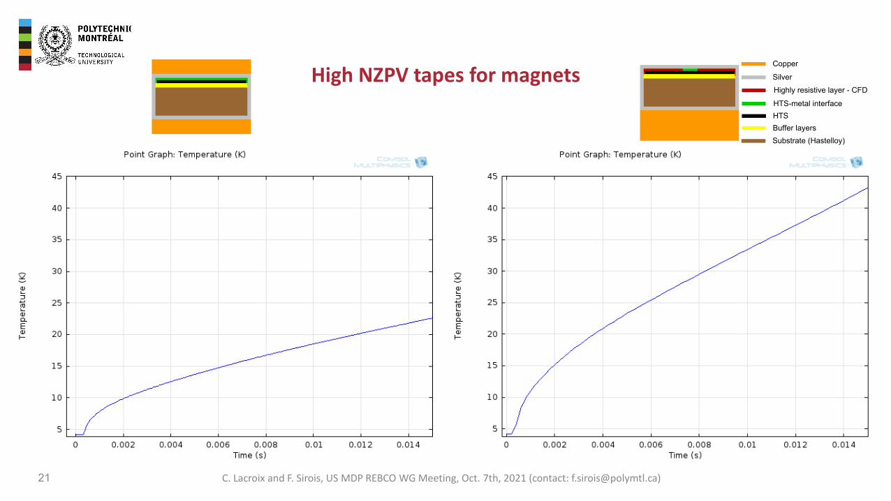
High NZPV tapes for magnets
21 C. Lacroix and F. Sirois, US MDP REBCO WG Meeting, Oct. 7th, 2021 (contact: [email protected])
22
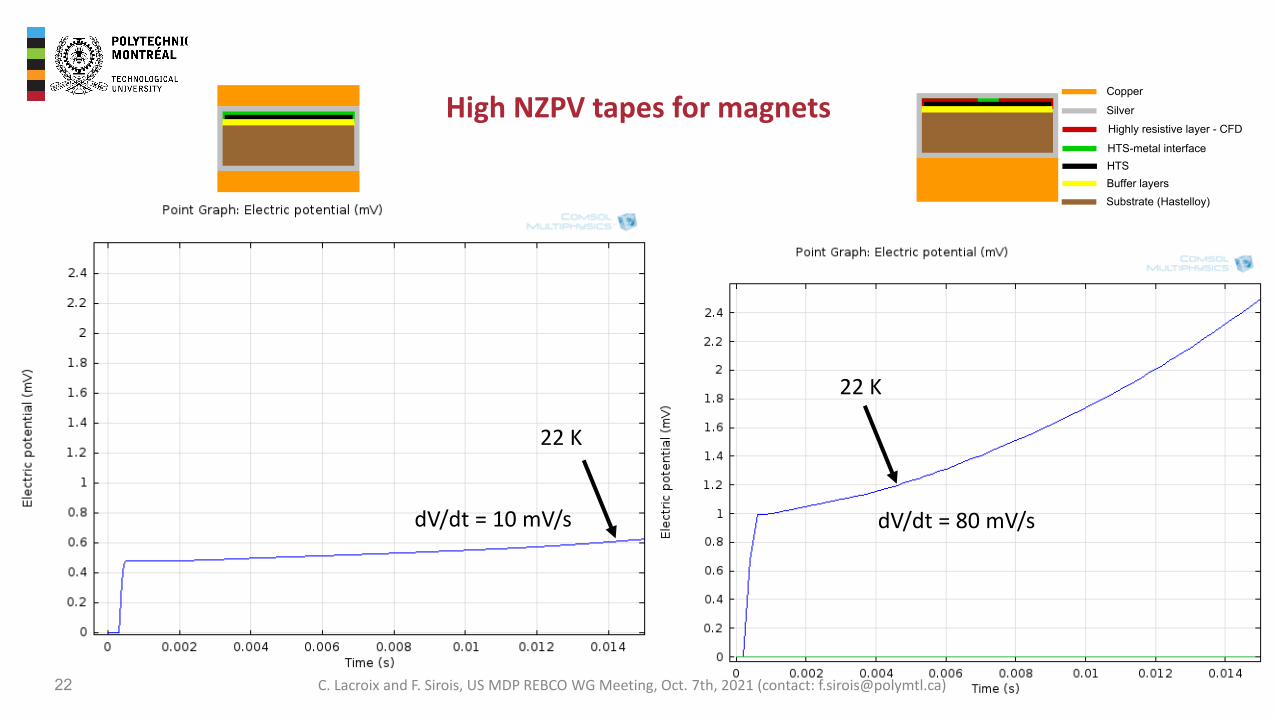
22 K
22 K
dV/dt = 10 mV/s dV/dt = 80 mV/s
Buffer layers
HTS-metal interface
Silver
Substrate (Hastelloy)
HTS
Highly resistive layer - CFD
Copper
High NZPV tapes for magnets
C. Lacroix and F. Sirois, US MDP REBCO WG Meeting, Oct. 7th, 2021 (contact: [email protected])

Minimum Quench Energy (MQE) vs Iop (operating current): measurements
23
SuperPower SF4050Ic = 102 A @ 77K, 2 mm Ag
→ Reduced MQE in CFD tapes(tradeoff between NZPV and MQE)
→ Reduction less pronounced as we increase Iop
Lacroix et al., ASC2014.
C. Lacroix and F. Sirois, US MDP REBCO WG Meeting, Oct. 7th, 2021 (contact: [email protected])

Future work
24 C. Lacroix and F. Sirois, US MDP REBCO WG Meeting, Oct. 7th, 2021 (contact: [email protected])
What else now?
- Pursue work on long-length CFD tapes
- New focus on high field magnets- Canadian proposals currently in elaboration- Targeted timeline: April 2022-March 2027
- In parallel, we try to- Learn more from literature and experts in the field- Identify lacks in knowledge and numerical tools impeding the R&D

Questions of importance already identified
25 C. Lacroix and F. Sirois, US MDP REBCO WG Meeting, Oct. 7th, 2021 (contact: [email protected])
- What is the quench behavior of REBCO cables using CFD tapes? How does it compare to the REBCO cables with nominal REBCO tapes?
- How does current sharing depend oni) local Ic drops in REBCO tapes?ii) contact resistances between multiple tapes and/or cable metallic sheath?iii) termination resistances?
- Would CFD tapes work well with current HTS magnet quench detection systems? (if such a system even exists!)
- What kind of experiment would allow confirming these questions?
- etc.

26
514 340-4711 ext. [email protected]
C. Lacroix and F. Sirois, US MDP REBCO WG Meeting, Oct. 7th, 2021 (contact: [email protected])