reasserting the fundamentals of systems analysis and ... · typically offer a system analysis and...
TRANSCRIPT

Information Systems Education Journal (ISEDJ) 10 (2) June 2012
©2012 EDSIG (Education Special Interest Group of the AITP) Page 67 www.aitp-edsig.org /www.isedj.org
Reasserting the Fundamentals of
Systems Analysis and Design through the Rudiments of Artifacts
Musa Jafar [email protected]
Jeffry Babb
Department of Computer Information and Decision Management West Texas A&M University
Canyon, TX 79016
Abstract In this paper we present an artifacts-based approach to teaching a senior level Object-Oriented Analysis and Design course. Regardless of the systems development methodology and process model, and in order to facilitate communication across the business modeling, analysis, design, construction and deployment disciplines, we focus on (1) the ability to define the boundaries of the system through context analysis, (2) the separation between business needs and technology requirements (business requirements vs. software requirements specifications), (3) the clear separation between analysis and design (business-domain models vs. analysis models vs. design models), (4) the evolution of artifacts from domain artifacts, to analysis artifacts and to design artifacts, and (5) the application of abstractions, formal methods and patterns to produce the necessary design artifacts. Thus, we emphasize the transition from computation-independent models, to platform-independent models, to platform-specific implementation models. We assert that the qualities of the produced artifacts convey the essentials of a student’s understanding of analysis and design. In this sense, as students engage the artifacts of design, they converse with the problem and solution space in a manner that strengthens their command of the interface between information systems and organizations. We assert that faculty teaching an Analysis and Design course should focus on the quality of artifacts that serve as the “meeting point or interface” between the problem space and the solution space rather than on the development methodology(s) and process model(s) involved. Keywords: Object Oriented, Analysis, Design, Use-case, object model, sequence diagram, artifacts
1. INTRODUCTION
Systems analysis and design persists as a core concern for the Information Systems discipline and programs designed to instruct students in the fundamentals of Information Systems. Systems analysis and design remains a core concern as the processes and artifacts of analysis and design reconcile between the
technical and organizational concerns for any information system. While the composition and depth of curricular content in analysis and design have always been debatable, the curriculum in analysis and design has always been influenced by: (1) the structure of the academic program; (2) the skill set of the faculty teaching the course; (3) the experience

Information Systems Education Journal (ISEDJ) 10 (2) June 2012
©2012 EDSIG (Education Special Interest Group of the AITP) Page 68 www.aitp-edsig.org /www.isedj.org
of the faculty in software development; (4) the set of tools used in the course; (5) the paradigm used to teach the course (Object-Oriented, structured, etc.); and (6) the position of the course in the program curriculum (Russell, Tastle, & Pollacia, 2003).
Generally, our concern with systems analysis and design is in developing (1) an in-depth understanding of the problem domain; and (2) a multi-contextual (Analysis, Design, Construction, Testing and deployment) communication of descriptions regarding the solution domain. These elements have been well-articulated: “To program is to understand: The development of an information system is not just a matter of writing a program that does the job. It is of the utmost importance that development of this program has revealed an in-depth understanding of the application domain; otherwise, the information system will probably not fit into the organization. During the development of such systems, it is important that descriptions of the application domain are communicated between system specialists and the organization.” (Madsen et al., 1993, p.3)
In a course on systems analysis and design, it is quite common that, in addition to systems analysis and design topics, faculty also tend to focus heavily on the development process itself. As a design process model suggests operations at a higher order of analysis, some of these topics are difficult for students to comprehend. Put another way, the concerns of process are premature for students who must first grasp the fundamentals of the artifacts of analysis and design, and particularly, of design. Furthermore, some related subjects, such as user interface design and database design, often require separate courses despite their obvious connection to the concerns of systems analysis and design. Similarly, operating in a development environment, preparing the deployment environment, designing for scalability, designing for quality assurance, and configuration management are hard to teach in a classroom - they typically require many years of experience and on-the-job training. Accordingly, educators need to be very selective of the content they teach and the prerequisites needed as they need to concentrate on the core topics of analysis and design.
To teach students how to analyze, design, build and maintain useful and usable software system products (Brooks, 1995), IS programs typically offer a system analysis and design
course that focuses on requirements gathering, analysis, and high-level design as an essential element of the undergraduate curriculum. Also, if complemented by a capstone “finishing” and synthesizing course, a course in systems analysis and design can also focus on low-level design, construction, testing, deployment, and packaging. These two courses cover the major aspects of the factory-life phases of a software system product in contrast to its lifetime-in-use. Throughout this curricular process, students learn about the tools, processes, artifacts, and quality-assurance aspects of what is needed to build a software system product (Brooks, 1995; Gupta and Wachter, 1998).
This paper illustrates how we address the following questions in teaching the students how to perform analysis and design: (1) where do we start the analysis and design process? (2) What are the activities that are performed? (3) What are the artifacts that are produced? (4) What are the dependencies between the different artifacts? (5) How to evolve domain artifacts to analysis artifacts to design artifacts to development artifacts? (6) How to use UML tools to support and automate the creation, maintenance and transition of artifacts? This artifacts-centered, UML-Tools based approach focuses our students on the rudiments of systems analysis and design by focusing on the quality of artifacts and their evolution that facilitate these activities. By the time, our students start their profession, they should be comfortable and versant in the rudiments of the SAD course as they pertain to the essential artifacts of design. Given a description of a business problem from a subject matter expert, our students should be able to identify their business needs in the form of business requirements and system requirements. They should be able to produce the appropriate system context, functional architecture, use-cases and use-case diagrams. Given a use-case, they should be able to produce the object models, sequence diagrams and activity diagrams and screen layouts. Given an object model, they should be able to produce the conceptual database schema. Given a conceptual database schema, they should be able to produce the logical database schema (SQL DDL(s)) etc. This is a simpler, and perhaps not-synthesized, level of understanding, but it is focused on the outcome of mastering the basics.

Information Systems Education Journal (ISEDJ) 10 (2) June 2012
©2012 EDSIG (Education Special Interest Group of the AITP) Page 69 www.aitp-edsig.org /www.isedj.org
Explicating our Exemplar
In our program, our first course in systems analysis and design is a junior/senior level course. For a textbook, we have used “Applying UML and Patterns: An Introduction to Object-Oriented Analysis and Design” by Larman (2005), and supplemented by other course materials and Microsoft Word document templates from IBM Rational. For analysis and design software tools we use IBM Rational Architect. As reference texts, we use Requirements Management Using IBM Rational Requisite Pro (Zielczynski, 2008), Visual Modeling with IBM Rational Software Architect (Quatrani & Palistrant, 2006), and UML and IBM Rational Unified Process Reference and Certification Guide (Shuja & Krebs, 2008). We use IBM Rational Software Architect as a UML-based CASE tool. IBM Rational Architect provides support for creating, sharing and managing of UML models during analysis and design. It is used as a repository and a management tool for the various artifacts across the team members (model, documents, etc.) (Quatrani & Palistrant, 2006). Figure 1 IBM Rational: User ViewFigure 1 is a screenshot a user’s view of the tool’s frontend, it allows analyst designers and developers to collaborate and share the various analysis and design artifacts (models and documentation) into a repository with visual front-end. All IBM Rational software and educational materials are available free of charge for academic programs participating in the IBM Rational Academic Initiative Program.
Our course has object-oriented programming and database design as pre-requisites. For homework assignments, students are required to produce the necessary analysis and design artifacts using a combination of Word documents (using IBM Rational document templates) and UML models using IBM Rational Software Architect. For the final project, students work in teams to produce the complete analysis and design artifacts (Word documents, UML models, and prototype demos).
In this paper, we share an artifacts-based approach in the delivery of our Object-Oriented Systems Analysis and Design course. By “artifacts-based” approach, we mean that regardless of the software engineering methodology and process model (Agile, Unified, SCRUM, Extreme Programming, etc.), we focus on the artifacts, their dependencies and transformation that lead to the construction of the product. The Rational Unified Process lists
twenty-one analysis and design artifacts (Crain, 2004), some of the artifacts are redundant and they do overlap we do not cover all of the artifacts in the course. In this paper, we emphasize on the structure of six primary artifacts (System Context, Requirements, Use-Case Modeling, Object Modeling, and State Diagrams) and activity diagrams. We hold that such an emphasis strengthens the perceptive skills students require in order to understand the wider process of systems development. A focus on the qualities and mechanics of the analysis and design artifacts serves to remind students about the role these artifacts play as an interface between the ‘inner’ environment, the substance and organization of the artifact itself, and an ‘outer’ environment, the surroundings in which it operates.” (Simon, 1996)
2. THE ANALYSIS DISCIPLINE
To analyze a system is to build a set of consistent and interrelated models on the basis of which a software system can be designed. During analysis, we define:
(1) The boundaries of the system represented as a UML system context model.
(2) The users of the system represented as a set of primary and secondary actors.
(3) The functional requirements of each actor(s) group organized and described in a Word document (explicitly listing capabilities requirements – the “should” and “should-nots”).
(4) The business logic of the elementary business processes of the system represented as UML diagrams (use-case, system sequence, collaboration diagrams, and activity diagrams) and a Word document containing descriptions of use-case scenarios.
(5) The information models of the system represented as UML domain object models.
(6) The functional architecture of the system represented as UML functional subcomponents.
(7) The software requirements specifications of the system (non-functional or other requirements depending upon what it is named) which also includes performance, reliability, security, and other concerns.
Essentially, the analysis team produces robust and consistent professional documents and rich graphical models using a word processor and a modeling tool such as IBM Rational Architect. Accordingly, the analysis team produces artifacts

Information Systems Education Journal (ISEDJ) 10 (2) June 2012
©2012 EDSIG (Education Special Interest Group of the AITP) Page 70 www.aitp-edsig.org /www.isedj.org
related to documenting an expressive platform independent model on the basis of which the system can be designed.
Where to Start?
Software development is the art of moving forward. To overcome the “analysis paralysis” dilemma, the challenge facing the designer is: to orbit sufficiently in problem-domain modeling to generate enough momentum to begin analysis; to orbit sufficiently in analysis to gather enough momentum to move to design; etc. One of the biggest challenges is to teach students where to start. The artifacts of design create the milestones for an analysis and design project and signal to the designers that we have gathered enough quality artifacts to move forward, partially or completely, to the next phase.
We start by defining the system context. By doing so, we define the boundaries of the system. We define the primary actors (both humans and other applications) and the secondary actors of the system. The system context is typically conveyed in a Word document that details the characteristics of each actor group accompanied by UML architectural models that highlights the primary and secondary actors of the system and their patterns of interaction with the system through system-level sequence diagrams. We use the actors list defined in the system context to define and produce the functional requirements document and the functional architecture model, see Figure 1. We use the functional requirements to detail the use-case scenarios and produce the use-cases document, use-case models and system sequence diagrams models. For human-actors we produce detailed sequence diagrams user interfaces and storyboards, for application-actors we produce contract (API) specifications. We then use the use-case scenarios to build bottom-up domain object models. We use the domain object models to produce the state transition diagrams of the noteworthy objects. We use the analysis models and software requirements specifications to produce the design models. We use the use-cases, system requirements and domain models to produce system architecture and the detailed design.
The System Context
The system context artifact starts as a UML model. It documents the primary and secondary actors of the system and their characteristics. It
allows us to define the boundaries of the systems. The system context is the primary input to the functional requirements of the system. It helps us define (1) primary business actors (both human and other systems) that require services from the system, (2) the primary system administrator actors responsible for administering and maintaining the system, and (3) the secondary actors (which are other systems) that are in the workflow of the elementary business processes of the primary actor(s).
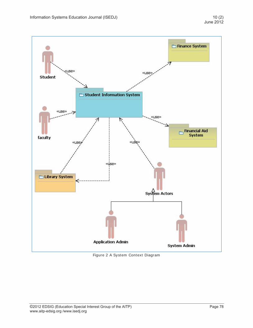
The analysis domain is not without its difficulties, as analysis is where we reconcile between the technical and organizational concerns in the identification of actors. When defining primary actors, we sometimes have the tendency to ignore the serviceably of the system (primary system actors); we do, however, emphasize that there is always an application administrator actor, a system administrator actor, and in some cases a service layer monitor actor (another system that may have to monitor the health of the application). Primary application actors are responsible for the monitoring, operations support, administration, backup, recovery, maintenance and serviceability of the application. They have their own “System-Level” functional requirements to perform their operations. Using a Student Information System as an example, the system context in Figure 2 shows Student(s), Faculty, the Library System, Application Admin, and System Admin as primary actors, and the Finance System, the Financial Aid System and the Library System as secondary actors. We are highlighting the Library System as both a primary and a secondary actor to make the point that an actor can be both primary and secondary. Within the UML tool front-end, as illustrated in Figure 1, we can capture the characteristics of each actor group and provide text description within the document editor or attach a document detailing the characteristic of the actor group as a URL.
The Requirements
A requirement is a service that the system needs to provide or a capability to which the system needs to conform to. Although completely different, requirements are usually divided into (1) the functional or business requirements that capture the business functions of the system and (2) the system requirements (Software requirements specifications) that provide the scaffolding and the infrastructure support of the

Information Systems Education Journal (ISEDJ) 10 (2) June 2012
©2012 EDSIG (Education Special Interest Group of the AITP) Page 71 www.aitp-edsig.org /www.isedj.org
business functions of the system. Depending on the software engineering methodology used, the system requirements are also called the nonfunctional, other, or supplementary requirements. UML allows for the modeling of functional requirements through use-case diagrams, system sequence diagrams, and activity diagrams. UML however, does not provide a framework for modeling system requirements. The requirements document is a well-written Word document that includes both the functional and system requirements of the proposed system. It clearly captures the functional and the non-functional requirements of the system. Figure 3 illustrates a sample table-of-contents for a requirements document that our students use as a template. We provided the figure to emphasize the importance of uniformity of content, and as a road map of what to expect from analysis and design in terms of content and deliverables. Students have always struggled with how a document should look like, what to include in the project documentation, the table-of-content provides them with a road map of what to expect in terms of artifacts and content and their level of detail.
The Functional Requirements
The functional requirements are the business capabilities that the system should provide. They are written in a request for proposal (RFP) format by, or at least with the assistance of, subject matter experts. These requirements are written in clear and unambiguous short paragraphs (as capabilities expressed in terms such as “should” and “should-not”), with one- or two-paragraph descriptions to provide a high-level understanding of the capability or the restriction.
For each primary actor, we create categorized lists of business functions that reflect the business needs of the actor group. The following is a sample of functional requirements listings: 1) Student Requirements
1 A student should be able to add a course section to their Schedule. During the registration period, using the internet, a student should be able to add a course section to their schedule from the list of open sections as long as it does not exceed the maximum allowed limit for that student.
2 A student should be able to delete a course section from their schedule. During the drop period, using the internet, a student should be able to drop a course section from their schedule as long as they maintain the minimum residency limits.
2) Catalogue dept. Requirements 1 Catalogue dept. should be able to change prerequisites of an existing course. …………
2 Catalogue dept. should be able to assign a course to a degree plan.
3) Etc.
In summary, the functional requirements provide a list of capabilities and restrictions. It is an input to the use-case documents where business logic is detailed.
The System Requirements
The system requirements are capabilities the system needs to conform to. According to Zielczynski (2008), they are all the requirements that cannot be expressed in use-cases. They drive the design and specify the system properties. They are categorized into aspects covering security, performance, reliability, usability, testing, technology, external interfaces, operations support, legal concerns, etc.
Although two software systems may have very different functional requirements (Billing vs. HR), it is often the case that they have very similar system requirements. System requirements are usually based on common corporate and industry best practices and standards (IEEE Computer Society, 1998). According to their level of interest in the system, various stakeholders write the system requirements. For example, security engineers write security requirements that comply with corporate and industry standards. Maintenance, operations support and system administrators write serviceability requirements. Database administrators write the data requirements. User-centered design (human factors) groups write the usability requirements to comply with the look and feel standards of the organization.
The system requirements document is an input to the use-case details document, system

Information Systems Education Journal (ISEDJ) 10 (2) June 2012
©2012 EDSIG (Education Special Interest Group of the AITP) Page 72 www.aitp-edsig.org /www.isedj.org
architecture document, deployment architecture, and test cases.
The following is a sample of system requirements listings:
1) The System should respond to a
user request for a service within 3-5 seconds 90% of the time and no longer than 10 seconds at any time.
2) A user account should become in-active if it has not been used for a configurable (default 45) consecutive days.
3) A user should not be able to have more than one concurrent active session.
4) The date, time and the IP address of the machine from which a user logged in should be stored into the system.
5) No Open Source code should be used as part of the System
6) All System Windows should have a title that reflects the task at hand, should display the user name and should display the current local date and time.
7) All System windows should have context help.
8) All necessary data should be carried over across multiple active screens
9) Stale records that are more than a configurable (default one year) old should be purged out of the system.
10) The System should support single sign-on products.
11) Security should be X507 Compliant. 12) Client and Server Ports should be
configurable.
The Use-Case Model
Use-case modeling is comprised of use-case UML diagrams and use-case details that are textual documents. Use-case diagrams are representations of each actor, their underlying use-cases, and the dependencies between use-cases (extends and includes). The business logic of functional requirements is detailed in the use-case details document(s). Each functional requirement is traced to one or more concrete use-cases and each concrete use-case is traced back to one or more functional requirements. A concrete use-case details an elementary business process. It is a coherent set of functions, which embodies the business logic
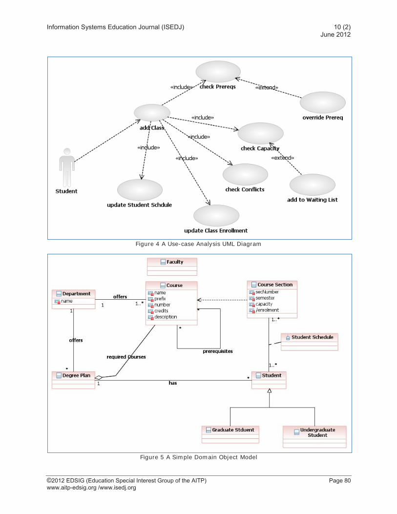
needed for the system to provide while moving the system from one consistent state to another consistent state in response to an actor’s request for service. During analysis, abstract use-cases are extracted from the concrete use-cases. Abstract use-cases contain reusable business logic components that are common to more than one use-case. When a use-case is too big, it is also abstracted into a simpler set of use-cases to simplify the business logic through abstraction. For example, “check-prerequisites,” “get-probation-status,” and “validate-registration-card” are abstract use-cases of the “register-for-class” concrete use-case, Error! Reference source not found.. During analysis, use-case details are also captured as activity diagrams (see Figure 9).
Many sources provide templates for use-case documents. We use the templates from IBM Rational as a skeleton and we modify them as needed (Zielczynski, 2008). The following is a common use-case template:
<Use-case Name> 1. Brief Description 2. Satisfied Requirements List 3. <Use-case Name> 4. Brief Description 5. Satisfied Requirements List 1. <Requirement Name a& Number> 2. <Another Requirement Name & Num.>
6. Actors List 1. <Actor Group Name> 2. <Another Actor Group Name>
7. Preconditions 1. <Precondition> 2. <Another precondition>
8. Use-case Flow 1. Basic Main Flow 2. Alternative Flows 3. Optional Flows 4. Exception Flows
9. Post Conditions 1. <Post Condition> 2. <Another Post Condition>
10. Included Use-cases 1. <Use-case Name and Number> 2. <Another Use-case Name and Num.>
11. Special Requirements 1. <Special Requirement> 2. <Another Special Requirement>
12. Special System Requirements 1. <Special System Requirement> 2. <Another System Requirement>
13. Assumptions, Open Issues and Comments

Information Systems Education Journal (ISEDJ) 10 (2) June 2012
©2012 EDSIG (Education Special Interest Group of the AITP) Page 73 www.aitp-edsig.org /www.isedj.org
The Domain Object Model
The domain object model is the set of domain objects, the attributes of each object with their constraints and data types, and the set of associations between objects. Associations have cardinality and are regular, aggregation, containment, inheritance or taxonomic. The domain object model is a UML artifact that is comprised of a set of diagrams and the underlying descriptions and semantic content of the object model artifacts. In summary, it is a visual representation of the domain objects of the system, their attributes, constraints and associations with other classes. Each use-case scenario exposes certain objects, object attributes and relationships. For example, from a login use-case, we learn that a user (student, faculty, staff, etc.) has a user id and a password. From the “add class” use-case scenario, we learn that students have study plans and majors, and courses have prerequisites. By analyzing the use-cases, the object model is built from the ground up. In Figure 5 is an example of a mini object model.
The State Diagrams
For each domain object, a state diagram captures the noteworthy, finite, and discrete states of an object. Not every object necessarily has noteworthy states. State transitions of the same object are usually confused with the inheritance hierarchy of an object. For example, a student status as freshman, sophomore, junior, or senior represents the possible state transitions of the undergraduate student object rather than as subclasses of student. Figure 6 is an example of a state transition diagram of the object student
3. THE DESIGN DISCIPLINE
Design is an intermediate phase in the process of moving the system from the problem space (Analysis) to the solution space (Final Product). To design a system is to develop a set of artifacts – and subsequently an overall system model – from which a software system can be built. Given the set of all the Analysis artifacts, time constraints, technology constraints, and financial constraints, the system design is a proposal for feasible solution that satisfies these constraints. During design, inputs, processing, data storage, output and communication software artifacts are materialized into a set of layered architectures that are comprised of user-
layers, processing layers, data layers, communication layers, security layers, etc. In this sense, designing is about making commitments on the distribution of business logic and the processing of business logic across the layers.
From Analysis to Design
Transitioning from analysis into design, students have learned how to create analysis models and document (1) the system context with its primary and secondary actors, (2) the functional architecture of the system and the dependencies between its functional components, (3) the requirements of the system both functional and system requirements, (4) use-cases and use-cases analysis and (5) the domain object model, (5) the user interface in terms of story boards and contract specifications.
During design, students learn how to realize a solution for the analyzed problem at hand. They build platform-independent models during high-level design and platform specific models during low-level design. During design, students learn to realize uses cases through use-layer components, processing layer components and data layer components. Using the web as a computing model, students realize that they need to (1) deign web pages based on the story of the use-cases, (2) design database tables based on the design object model and connect the user layers with the data layers using a dynamic content processor like PHP, Java Server Pages, Python, etc.
Into Design
During design, students learn:
To refine and redefine objects, create abstractions, add methods to objects, refine the data types and add constraints to attributes based on Class Responsibilities and Collaboration (CRC) design pattern as shown in Figure 11.
How to use the Model-View-Controller and Class-Responsibilities-And-Collaboration patterns to define the view components or boundary classes if any (Screen designs and layouts), controller components or processing classes (class responsibilities and collaborations) and Model components or entity classes (tables and views of the underlying data layer is a relational database system). For the Transcript object for example, students learn to produce the

Information Systems Education Journal (ISEDJ) 10 (2) June 2012
©2012 EDSIG (Education Special Interest Group of the AITP) Page 74 www.aitp-edsig.org /www.isedj.org
boundary (GUI), processing and entity (database) realizations as shown in Figure 12.
How to use design patterns to create other design objects such as control classes, listener classes, messaging classes, information expert classes, etc.
How to utilize knowledge learned in their database class to implement design and implement a relational database with the required integrity constrains.
In summary, during design, use-cases are realized into detailed sequence diagrams where commitments are made as to the distribution of processing. For example, given a login use-case, should the processing to validate a user be performed in the user layer, the processing layer, or in the data layer through stored procedures? Each one of these designs has its own advantages and disadvantages. During design, a commitment as to how to implement the business logic is clearly outlined.
Using a student login to the system use-case scenario, students learn to identify the design objects of the use-case Figure 7. A design commitment needs to be made as to who is responsible for validating the credentials. Students learn to produce detailed sequence diagrams to realize the design of use-cases. In Figure 8, the “Login-Screen” object controls all the authentication operations and the creation of other objects.
However, another sequence diagram could have distributed the logic among the various objects. Accordingly, design is a commitment to a processing logic scenario that is low coupled and highly cohesive.
From Analysis and Design to Design and Development
It is prudent to identify what has been left out of our discussion, as these left-out parts are a also a vital component of our systems analysis and design curricular sequence, but are included in our capstone course. To wit, there are other important design issues for which a rudimentary and artifacts-centered approach is also appropriate. A few of these issues that we feel are important are: (1) testing; (2) designing for performance; (3) designing for scalability; (4) designing for security; and (5) designing for robustness. As such, each of these are deferred to our capstone course, which itself is a synthesizing course meant to bring the principle pillars of our curriculum together.
To some degree, we can think of these as intermediary concerns, and are, appropriately, left to a course focused on culminating the rudiments and undertaking a deeper study of software processes: our senior capstone course. Once students have grounded themselves in systems analysis and design, modern object-oriented programming, advanced web programming, and database management, we feel that these additional concerns of design can then be addressed in the richer context of a business problem in need of an information technology solution. Once past the rudiments, even a capstone course is merely a beginning; students will only learn about designing for performance, scalability, and robustness in the context of practice in the profession. While we feel it is prudent to discuss these issues, the “laboratory” environment of the capstone project course makes it difficult, but not impossible, to demonstrate these important design issues. That is to say, while our capstone course seeks to involve students in projects with real clients and attempts to provide as meaningful of an experience as would be possible, most capstone courses, including ours, are far from the pressures, constraints, and strictures of reality. Typically, these projects are either a pilot/prototype project, or some other non-essential product that is typically NOT on the critical path. However, we have enjoyed notable exceptions to this. For instance, we have experience with on-campus clients who have either gone on to utilize the outcomes of our capstone course in their daily operations, or have been very impressed with the outcomes of the capstone course and have incorporated our students’ work in some fashion.
4. DISCUSSION AND CONCLUSION
In this paper we presented a road-map for an outcomes-focused, artifacts-based, hands-on, and disciplined approach to an analysis and design course. Our objective is to present a disciplined approach to understanding and producing the necessary analysis and design artifacts (documents and models) which consistently lead to a successful system regardless and irrespective of the systems development paradigm, model, and methodology used to build the system. With this approach, students gain hands-on technical skills that are deliverables-centric. Our premise is that the adherents of a predictive model, such as the Capability Maturity Model, or the

Information Systems Education Journal (ISEDJ) 10 (2) June 2012
©2012 EDSIG (Education Special Interest Group of the AITP) Page 75 www.aitp-edsig.org /www.isedj.org
adherents of an adaptive model, such as Extreme Programming, should both be equally comfortable with commonly accepted artifacts. We also acknowledge that bridging the gap between process modeling and object-oriented systems modeling remains a challenge; we contend that students will bridge this gap with experience. However, without a solid grounding in the qualities and characteristics of the artifacts themselves, the “craft” of systems design will be elusive. We think of the artisan who must learn the tools of their craft before they worry about the holistic and philosophical concerns of their craft. In this sense, we feel that we are preparing our students to use their knowledge of the characteristics and qualities of design artifacts to then develop their experience.
We foresee that our students will approach their initial years in the profession as an opportunity to learn how their designing of artifacts and their interdependencies helps them to understand the systems they build and the context of the organizational problems these systems address. More importantly, by knowing their tools, our students can then focus on what is, and is not, possible as they navigate the complexity of systems specification. As they mature in their profession, our students must develop a sense of how the juxtaposition of the materials of design (the artifacts), the constraints of the design process, and the organizational constraints of the system’s intended operational environment, transform their understanding of the analysis and design process. This is so also in a cumulative and iterative tradition: experience is accrued as the design process is continually engaged. We err on the side of the artifacts-based approach as we believe our students are better equipped to learn about the art and craft of systems designing if they are first aware of the indelible truth inherent in the characteristics and qualities of the artifacts of design.
Schön and Bennett (1996) put it well when they described a “reflective conversation with materials” that designers conduct as they reflect on practice. In this case, “practice” is the consistent use of design artifacts, which is only possible when design artifacts (the materials of designing) are well-understood. We see this in other areas which invite mastery: those learning the piano practice and exercise in the structures of chords, notes and scales; those learning to dance exercise in the mechanics of movement; and those learning a team sport exercise in the patterns of play. Accordingly, in
our course we have chosen to focus on the artifacts of design in our curriculum. Once armed with the “scales” and building-blocks of design artifacts, we believe that our students can design within the framework of a development model in the same manner that a musician trained in the virtues of sight-reading can work within the context of many styles of music. In this sense, familiarity with the artifacts of design – the rudiments – students will have comfort with a “grammar” of design which will serve as a repertoire to draw from in future practice.
Most fundamental to our approach is that the characteristics and qualities of the artifacts of design provide the best interface between the system and those that will use the system. In the artifacts, we have a “lingua franca” which allows the realm of Information Technology to understand and accommodate the realm of the organization. This interfacing is at the heart of the Information Systems discipline and is most representative of the skills and knowledge most suited to our students’ development.
4. REFERENCES
Alter, S. (2006). Pitfalls in Analyzing Systems in Organizations. Journal of Information Systems Education, 17(3), 295-302.
Brooks, F. P. (1995). The Mythical Man-Month. Addison-Wesley.
Cockburn, A. (2001). Writing Effective Use Cases. Addison-Wesley.
Crain, Anthony (2004). The simple artifacts of Analysis and Design, The Rational Edge (june-8-2004) http://www.ibm.com/developerworks/rational/library/4871.html?ca=dnp-326
Gamma, E., Helm, R., Johnson, R., & Vlissides, J. (1995). Design Patterns, Elements of Reusable Object-Oriented Software. Addison Wesley.
Gupta, J. and Wachter, R. (1998). A Capstone Course in the Information Systems Curriculum. International Journal of Information Management, 18(6), 427-441.
IEEE Computer Society. (1998). IEEE Recommended Practice for Software Requirements Specifications. IEEE Computer Society. New York, NY: IEEE Computer Society.

Information Systems Education Journal (ISEDJ) 10 (2) June 2012
©2012 EDSIG (Education Special Interest Group of the AITP) Page 76 www.aitp-edsig.org /www.isedj.org
Jacobson, I., Christerson, M., & Overgaard, G. (1992). Object-Oriented Software Engineering, A Use Case Driven Approach. Addison Wesley.
Larman, C. (2005). Applying UML and Patterns. Prentice Hall.
Madsen, O. L., Moller-Pedersen, B., & Nygaard, K. (1993). Object-Oriented Programming in the BETA Programming Language. Retrieved 6 12, 2010, from www.daimi.au.dk/~beta/Books/betabook.pdf:
Object Management Group. (2010, May 03). OMG Unified Modeling Language (OMG UML) Infrastructure, Version 2.3. Retrieved June 05, 2010, from http://www.omg.org/spec/UML/2.3/
Quatrani, T., & Palistrant, J. (2006). Visual Modeling with IBm Rational Software Architect. Upper Saddle River, New Jersey: IBM Press, Pearson Ed.
Rumbaugh, J., Jacobson, I., & Booch, G. (2005). The Unified Modeling Language Reference Manual. Addison Wesley.
Russell, J., Tastle, W., & Pollacia, L. (2003). The State of Systems Analysis and Design. ISECON. San Diego.
Schon, D.A. & Bennett, J. (1996). Reflective Conversation with Materials. Bringing Design to Software, Winograd, T. (Ed.). New York: ACM Press.
Shuja, A. K., & Krebs, J. (2008). IBM Rational Unified Process Reference and Certification Guide. IBM Press, Pearson Ed.
Simon, H.A. (1996). The Sciences of the Artificial, 3rd Edition. Cambridge: MIT Press.
Steinberg, D. H., & Palmer, D. W. (2004). Extreme Software Development. Pearson Prentice Hall.
Wand, Y. and Webber, R. (1993) On the ontological expressiveness of information systems analysis and design grammars. Information Systems Journal, 3(4), 1993, 217–237.
Zielczynski, P. (2008). Requirements Management Using IBM Rational RequisitePro. Upper Saddle River, New Jersey: IBM Press, Pearson Ed.

Information Systems Education Journal (ISEDJ) 10 (2) June 2012
©2012 EDSIG (Education Special Interest Group of the AITP) Page 77 www.aitp-edsig.org /www.isedj.org
APPENDIX
Figure 1 IBM Rational: User View
Attaching actor specifications document as a url-links.
Description of the Student actor using the document editor
Information Systems Education Journal (ISEDJ) 10 (2) June 2012
©2012 EDSIG (Education Special Interest Group of the AITP) Page 78 www.aitp-edsig.org /www.isedj.org
Figure 2 A System Context Diagram

Information Systems Education Journal (ISEDJ) 10 (2) June 2012
©2012 EDSIG (Education Special Interest Group of the AITP) Page 79 www.aitp-edsig.org /www.isedj.org
Figure 3 The Table of Contents for A Requirements Document
1. INTRODUCTION AND PURPOSE .................................................................................................................. 1 2. DEFINITIONS, ACRONYMS AND ABBREVIATIONS ............................................................................... 1 3. DEPENDENCIES AND REFERENCES .......................................................................................................... 1 4. DOCUMENT OVERVIEW AND TARGETED AUDIENCE ........................................................................ 1 5. CUSTOMERS AND OWNERS ......................................................................................................................... 1 6. REVISION HISTORY EVOLUTION .............................................................................................................. 1 7. PRODUCT OVERVIEW ................................................................................................................................... 2
7.1 PRODUCT PERSPECTIVE.................................................................................................................................. 2 7.2 SUMMARY OF CAPABILITIES [LATER] ............................................................................................................ 2
8. THE CURRENT FUNCTIONAL ARCHITECTURE .................................................................................... 2 8.1 THE CURRENT FUNCTIONAL ARCHITECTURE DIAGRAM ................................................................................ 2 8.2 <FUNCTIONAL COMPONENT NAME AND DESCRIPTION> ............................................................................... 2
9. STAKEHOLDERS AND STAKEHOLDER GROUPS PROFILES .............................................................. 3 9.1 <STAKEHOLDER GROUP NAME> .................................................................................................................... 3 9.2 <STAKEHOLDER GROUP NAME> .................................................................................................................... 3
10. USERS AND USER ROLES’ PROFILES .................................................................................................... 4 10.1 <USER-ROLE NAME [PRIMARY | SECONDARY] ACTOR> ................................................................................ 4 10.2 <USER-ROLE NAME [PRIMARY | SECONDARY] ACTOR> ................................................................................ 4
11. THE SYSTEM CONTEXT ............................................................................................................................ 5 12. FUNCTIONAL REQUIREMENTS .............................................................................................................. 6
12.1 <PRIMARY ACTOR GROUP ONE> ................................................................................................................... 6 12.1.1 Requirement .......................................................................................................................................... 6 12.1.2 Requirement .......................................................................................................................................... 6
12.2 <PRIMARY ACTOR GROUP TWO>................................................................................................................... 6 12.2.1 Requirement .......................................................................................................................................... 6 12.2.2 Requirement .......................................................................................................................................... 6
12.3 <COMMON REQUIREMENTS> ......................................................................................................................... 7 12.3.1 Requirement .......................................................................................................................................... 7 12.3.2 Requirement .......................................................................................................................................... 7
13. SYSTEM REQUIREMENTS ......................................................................................................................... 8 13.1 USABILITY ..................................................................................................................................................... 8 13.2 RELIABILITY .................................................................................................................................................. 8
13.2.1 <Reliability Requirement One> ............................................................................................................ 8 13.3 PERFORMANCE ............................................................................................................................................... 8
13.3.1 <Performance Requirement One> ........................................................................................................ 9 13.4 SUPPORTABILITY ............................................................................................................................................ 9
13.4.1 <Supportability Requirement One> ...................................................................................................... 9 13.5 DESIGN CONSTRAINTS ................................................................................................................................... 9
13.5.1 <Design Constraint One>..................................................................................................................... 9 13.6 ONLINE USER DOCUMENTATION AND HELP SYSTEM REQUIREMENTS ........................................................... 9 13.7 PURCHASED COMPONENTS............................................................................................................................. 9 13.8 INTERFACES ................................................................................................................................................... 9 13.9 USER INTERFACES .......................................................................................................................................... 9 13.10 HARDWARE INTERFACES ........................................................................................................................... 9 13.11 SOFTWARE INTERFACES ............................................................................................................................. 9 13.12 COMMUNICATIONS INTERFACES ................................................................................................................ 9 13.13 LICENSING REQUIREMENTS ...................................................................................................................... 10 13.14 LEGAL, COPYRIGHT AND OTHER NOTICES ............................................................................................... 10 13.15 APPLICABLE STANDARDS ......................................................................................................................... 10
14. SUMMARY AND CONCLUSIONS ............................................................................................................ 11 15. OPEN ISSUES ............................................................................................................................................... 12 16. APPENDIX LIST .......................................................................................................................................... 13 17. REFERENCES LIST .................................................................................................................................... 14 18. INDEX ............................................................................................................................................................ 15
Information Systems Education Journal (ISEDJ) 10 (2) June 2012
©2012 EDSIG (Education Special Interest Group of the AITP) Page 80 www.aitp-edsig.org /www.isedj.org
Figure 4 A Use-case Analysis UML Diagram
Figure 5 A Simple Domain Object Model

Information Systems Education Journal (ISEDJ) 10 (2) June 2012
©2012 EDSIG (Education Special Interest Group of the AITP) Page 81 www.aitp-edsig.org /www.isedj.org
Figure 6 State Transitions of an Undergraduate Student
Figure 7 A design Object Model of Login Use-case

Information Systems Education Journal (ISEDJ) 10 (2) June 2012
©2012 EDSIG (Education Special Interest Group of the AITP) Page 82 www.aitp-edsig.org /www.isedj.org
Figure 8 Login Sequence Diagram One

Information Systems Education Journal (ISEDJ) 10 (2) June 2012
©2012 EDSIG (Education Special Interest Group of the AITP) Page 83 www.aitp-edsig.org /www.isedj.org
Figure 9 A Skeleton Activity Diagram for Add Course

Information Systems Education Journal (ISEDJ) 10 (2) June 2012
©2012 EDSIG (Education Special Interest Group of the AITP) Page 84 www.aitp-edsig.org /www.isedj.org
Figure 10 Functional Architecture
Figure 11 Platform Independent Model

Information Systems Education Journal (ISEDJ) 10 (2) June 2012
©2012 EDSIG (Education Special Interest Group of the AITP) Page 85 www.aitp-edsig.org /www.isedj.org
Figure 12 User, processing and Storage Realizations of the Transcript Object