reasoning on uml class diagrams - dis.uniroma1.itdegiacom/papers/2005/bcdaij05.pdfenvironment for...
TRANSCRIPT

Reasoning on UML Class Diagrams
Daniela Berardi a, Diego Calvanese b, andGiuseppe De Giacomo a
aDipartimento di Informatica e Sistemistica, Universita di Roma “La Sapienza”,Via Salaria 113, I-00198 Roma, Italy
bFaculty of Computer Science, Free University of Bolzano/Bozen,Piazza Domenicani 3, I-39100 Bolzano, Italy
Abstract
UML is the de-facto standard formalism for software design and analysis. To sup-port the design of large-scale industrial applications, sophisticated CASE tools areavailable on the market, that provide a user-friendly environment for editing, stor-ing, and accessing multiple UML diagrams. It would be highly desirable to equipsuch CASE tools with automated reasoning capabilities, such as those studied in Ar-tificial Intelligence and, in particular, in Knowledge Representation and Reasoning.Such capabilities would allow to automatically detect relevant formal properties ofUML diagrams, such as inconsistencies or redundancies. With regard to this issue,we consider UML class diagrams, which are one of the most important componentsof UML, and we address the problem of reasoning on such diagrams. We resortto several results developed in the field of Knowledge Representation and Reason-ing, regarding Description Logics (DLs), a family of logics that admit decidablereasoning procedures. Our first contribution is to show that reasoning on UMLclass diagrams is EXPTIME-hard, even under restrictive assumptions; we provethis result by showing a polynomial reduction from reasoning in DLs. The secondcontribution consists in establishing EXPTIME-membership of reasoning on UMLclass diagrams, provided that the use of arbitrary OCL (first-order) constraintsis disallowed. We get this result by using DLRifd , a very expressive EXPTIME-decidable DL that has been developed to capture typical features of conceptual andobject-oriented data models. The last contribution has a more practical flavor, andconsists in a polynomial encoding of UML class diagrams in the DL ALCQI, whichessentially is the most expressive DL supported by current state-of-the-art DL-basedreasoning systems. Though less expressive than DLRifd , the DL ALCQI preservesenough semantics to keep reasoning about UML class diagrams sound and complete.Exploiting such an encoding, one can use current DL-based reasoning systems ascore reasoning engines for a next generation of CASE tools, that are equipped withreasoning capabilities on UML class diagrams.
Key words: Knowledge Representation, Description Logics, UML Class Diagrams,Computational Complexity, Verification, CASE Tools.
Preprint submitted to Elsevier Science 30 March 2005

1 Introduction
UML (Unified Modeling Language) is the de-facto standard formalism forthe analysis and design of software. One of the most important componentsof UML are class diagrams, which model the information on the domain ofinterest in terms of objects organized in classes and relationships betweenthem. 1 The use of UML in industrial-scale software applications brings aboutclass diagrams that are large and complex to design, analyze, and maintain.To simplify these tasks, sophisticated CASE tools are commonly adopted,e.g., Rational Rose 2 , Together 3 , Poseidon 4 , ArgoUML 5 (see also the OMGhome page 6 ). Such tools support the designer with a user-friendly graphicalenvironment for editing, storing, and accessing multiple UML class diagrams.However, the expressiveness of the UML constructs may lead to implicit con-sequences that can go undetected by the designer in complex diagrams, andcause various forms of inconsistencies or redundancies in the diagram itself.This may result in a degradation of the quality of the design and/or increaseddevelopment times and costs. If the diagrams were used simply for documen-tation purposes, then the problem could not be that severe; if, on the otherhand, they are used as part of a model-driven approach to development (see,e.g., OMG’s Model-Driven Architecture 7 ), then the quality of the models caninfluence the quality of the implemented system (especially, when a code gen-erator is involved, or when one uses models to generate test cases). Hence, itwould be highly desirable to equip CASE tools with capabilities to automat-ically detect relevant formal properties of UML class diagrams, such as thementioned inconsistencies and redundancies.
Several works propose to describe UML class diagrams using various kinds offormal systems [2–6]. Using such formal systems, one could potentially reasonon UML class diagrams, and formally prove properties of interest through in-ference, and hence help the designer in understanding the hidden implicationsof his choices when building a class diagram. However, in spite of these works,foundational questions remain open: how hard is it to reason on UML classdiagrams from the computational complexity point of view? Is there a formal-
1 In this paper we deal with UML class diagrams for the conceptual perspective, asopposed to the implementation perspective, see, e.g., [1].2 http://www.rational.com/products/rose/3 http://www.togethersoft.com/4 http://www.gentleware.com/5 http://argouml.tigris.org/6 http://www.omg.org/7 http://www.omg.org/mda/
2

ism equipped with sound and complete reasoning services that captures UMLclass diagrams and matches their intrinsic complexity?
In this paper we address such questions by resorting to results developedthrough the years in the Knowledge Representation and Reasoning communityon Description Logics (DLs) [7]. These are logics specifically designed for theconceptual representation of an application domain in terms of classes andrelationships between classes that admit decidable reasoning.
Our first contribution in this paper is to show that reasoning on UML class di-agrams is EXPTIME-hard even under fairly restrictive assumptions, namely:only binary associations, only minimal multiplicity constraints, generaliza-tions (between classes and associations) with disjointness and completenessconstraints. We get this result by exhibiting a polynomial reduction from rea-soning in the basic DL ALC 8 [7], which is EXPTIME-complete. In particularwe show that every ALC knowledge base can be expressed as a UML class di-agram preserving soundness and completeness of reasoning. This possibility isquite surprising, since UML class diagrams apparently have very limited meansto express negative and disjunctive information, namely disjointness and cov-ering constraints in generalization hierarchies. Instead ALC is equipped withunrestricted negation and disjunction; that is, it is able to treat negative in-formation in the same way as positive one, and to reason by cases to fully takeinto account disjunctive information.
Our second contribution is to establish EXPTIME-membership of reasoningon UML class diagrams, allowing for covering and disjointness constraintson generalization hierarchies but disallowing the use of arbitrary constraintsexpressed in the Object Constraint Language (OCL) [8]. OCL constraintsare essentially full first order logic formulas, hence they would make reasoningundecidable. We get this result by using one of the most expressive EXPTIME-decidable DLs studied so far, namely DLRifd [9,10]. This DL is equippedwith means to represent n-ary relations, identification constraints (i.e., keys),and functional dependency constraints on components of n-ary relations. Thislogic was developed with the aim of capturing conceptual and object-orienteddata models, and it is the final result of a series of studies on DLs with suchcapabilities [11–17]. The maturity of these studies is testified in the presentpaper by the fact that we are able to fully capture every UML class diagram asa DLRifd knowledge base: the DLRifd knowledge base is such that its modelsare exactly the possible instantiations of the UML class diagram (i.e., objectconfigurations that “conform” to the class diagram).
Our third contribution is more practically oriented. Indeed the ability of be-ing able to capture UML class diagrams using a DL suggests that we can use
8 In this paper when we mention reasoning in a DL, we always intend reasoningover a knowledge base expressed in that DL.
3

DL-based systems to reason on UML class diagrams. However current state-of-the-art DL-based reasoning systems [18,19] are not able to deal with n-ary re-lations, identification constraints, or functional dependency constraints. Theseconstructs are needed to fully capture in DLRifd the semantics of UML classdiagrams. However, due to a specific property of DLRifd models, namely thetree model property, we can get rid of such constructs while preserving soundand complete reasoning [9]. Exploiting this property, we propose a (polyno-mial) encoding of UML class diagrams in a simpler DL, called ALCQI [7],which is still EXPTIME-complete, but lacks the features above that are prob-lematic from an implementation point of view. Such a logic is essentially themost expressive DL that the current DL-based systems can support. The en-coding in ALCQI, while not preserving entirely the semantics of UML classdiagrams, preserves enough of it to keep reasoning sound and complete. Usingthis encoding we were able to validate, on industrial scale examples (namelythe UML class diagrams of the Common Information Model 9 , the feasibilityof the idea of using DL-based systems as core inference engines for reasoningon UML class diagrams.
Our work shows that DLs are a very promising technology for implementingcore reasoning engines for next generation CASE tools that are equipped withadvanced reasoning capabilities. This is a very interesting example of resultsand technology developed within Artificial Intelligence that can have a widespread approach in main stream industrial software.
The rest of the paper is organized as follows. In Section 2, we briefly dis-cuss UML class diagrams giving a natural formalization in first-order logic.In Section 3 we discuss various forms of reasoning on UML class diagramsand show examples of how they can be usefully exploited in order to detectinteresting properties of the diagram. In Section 4 we give the basic notionson DLs that we use later on. In Section 5 we present our EXPTIME-hardnessresult for reasoning on UML class diagrams, by showing a polynomial reduc-tion from reasoning in the EXPTIME-complete DL ALC. In Section 6 we showhow UML class diagrams not including general OCL constraints, but includingcovering and disjointness constraints on generalization hierarchies, can be fullycaptured in the EXPTIME-complete DL DLRifd , thus giving an EXPTIMEupper bound for reasoning on UML class diagrams. In Section 7 we show howUML class diagrams can be expressed in the simpler DL ALCQI, preservingenough semantics to keep reasoning on them sound and complete. In Section 8we discuss our experience in using state-of-the art DL-based reasoning systemsfor reasoning on the UML class diagrams of the Common Information Model.In Section 9 we briefly discuss related work. Finally, in Section 10, we drawsome conclusions.
9 http://www.dmtf.org/standards/standard_cim.php/
4

Phone
number[1..*]: String
brand: String
lastDialed(): String
callLength(String): Int
class name
attributes
operations
Fig. 1. Class of Example 2.1
2 UML class diagrams
UML class diagrams allow for modeling, in a declarative way, the static struc-ture of an application domain, in terms of concepts and relations betweenthem. We concentrate on UML class diagrams for the conceptual perspec-tive [8,1]. In particular, we do not deal with those features that are relevantfor the implementation perspective, such as public, protected, and private quali-fiers for operations and attributes. We describe the semantics of each constructof UML class diagrams in terms of first order logic (FOL). In the following,we call a model of the set of FOL formulas corresponding to the constructs inan UML class diagram an instantiation of the diagram.
2.1 Classes
A class in a UML class diagram denotes a set of objects with common features.A class is graphically rendered as a rectangle divided into three parts (seee.g., Figure 1). The first part contains the name of the class, which has tobe unique in the whole diagram. The second part contains the attributes ofthe class, each denoted by a name, possibly followed by the multiplicity, andwith an associated type 10 , for the attribute values. The third part containsthe operations of the class, i.e., the operations associated to the objects of theclass. Note that both the second and the third part are optional. Formally, aclass C corresponds to a FOL unary predicate C.
Example 2.1 Figure 1 models the class phone, characterized by the attributesnumber and brand, both of type String, and by the operations lastDialed(),which returns the last number called, and lengthCall(String), which returnsthe duration time of the call given as input. ¤
An attribute a of type T for a class C associates to each instance of C a set ofinstances of T . Attributes are unique within a class, but two classes may havetwo attributes with the same name, possibly of different types. An optionalmultiplicity [i..j] for a specifies that a associates to each instance of C at least
10 For simplicity, we do not distinguish between classes, i.e., collection of objects,and types, i.e., collections of values, such as integers, reals, . . . .
5

i and most j instances of T . When there is no upper bound on the multiplicity,the symbol ∗ is used for j. When the multiplicity is missing, [1..1] is assumed,i.e., the attribute is mandatory and single-valued. For example, the attributenumber[1..*]: String in Figure 1 means that each instance of the class has atleast one phone number, and possibly more, and that each phone number is aninstance of String. Formally, an attribute a of type T for class C correspondsto a binary predicate a for which the following FOL assertion holds:
∀x, y. (C(x) ∧ a(x, y)) ⊃ T (y)
i.e., for each instance x of class C, an object y related to x by a is an instanceof T . The multiplicity [i..j] associated to the attribute a can be expressed by
∀x. C(x) ⊃ (i ≤ ]{y | a(x, y)} ≤ j)
where (i ≤ ]{y | a(x, y)} ≤ j) is an abbreviation for the FOL formula withfree variable x expressing that there are at least i and at most j different y’ssuch that a(x, y) holds.
An operation of a class is a function from the objects of the class to whichthe operation is associated, and possibly additional parameters, to objects orvalues. An operation definition for a class C has the form
f(P1, . . . , Pm) : R
where f is the name of the operation, P1, . . . , Pm are the types of the mparameters, and R is the type of the result. 11 Observe that class diagrams donot focus on the actual definition of the function, and what is represented isthe signature (i.e., the name of the function and the number and the types ofparameters, where the object of invocation is an implicit parameter) and thereturn type of the function. Preconditions and postconditions, invariants andmore generally the behavior of the function can then be expressed using OCLconstraints as annotations (see Section 2.4).
Formally, such an operation corresponds to an (1 + m + 1)-ary predicatefP1,...,Pm , in which the first argument represents the object of invocation, thenext m arguments represent the additional parameters, and the last argumentrepresents the result. Observe that the name of the predicate depends on thewhole signature, i.e., it includes the types of the parameters.
11 Observe that a function returning multiple results can be represented by a func-tion returning a single tuple of results, i.e., a complex value.
6
C1
ml..mu
A
nl..nuC2
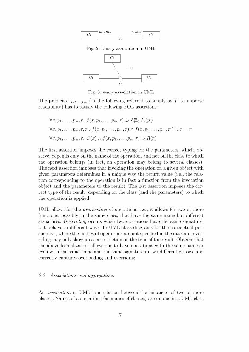
Fig. 2. Binary association in UML
C1
A
· · ·
C2
Cn
Fig. 3. n-ary association in UML
The predicate fP1,...,Pm (in the following referred to simply as f , to improvereadability) has to satisfy the following FOL assertions:
∀x, p1, . . . , pm, r. f(x, p1, . . . , pm, r) ⊃ ∧mi=1 Pi(pi)
∀x, p1, . . . , pm, r, r′. f(x, p1, . . . , pm, r) ∧ f(x, p1, . . . , pm, r′) ⊃ r = r′
∀x, p1, . . . , pm, r. C(x) ∧ f(x, p1, . . . , pm, r) ⊃ R(r)
The first assertion imposes the correct typing for the parameters, which, ob-serve, depends only on the name of the operation, and not on the class to whichthe operation belongs (in fact, an operation may belong to several classes).The next assertion imposes that invoking the operation on a given object withgiven parameters determines in a unique way the return value (i.e., the rela-tion corresponding to the operation is in fact a function from the invocationobject and the parameters to the result). The last assertion imposes the cor-rect type of the result, depending on the class (and the parameters) to whichthe operation is applied.
UML allows for the overloading of operations, i.e., it allows for two or morefunctions, possibly in the same class, that have the same name but differentsignatures. Overriding occurs when two operations have the same signature,but behave in different ways. In UML class diagrams for the conceptual per-spective, where the bodies of operations are not specified in the diagram, over-riding may only show up as a restriction on the type of the result. Observe thatthe above formalization allows one to have operations with the same name oreven with the same name and the same signature in two different classes, andcorrectly captures overloading and overriding.
2.2 Associations and aggregations
An association in UML is a relation between the instances of two or moreclasses. Names of associations (as names of classes) are unique in a UML class
7

C1
ml..mu
r1
A
r2
nl..nuC2
Fig. 4. Binary association with association class in UML
C1
r1
r2
C2
A
rn
. . .
Cn
Fig. 5. n-ary association with association class in UML
diagram. A binary association A between two classes C1 and C2 is graphicallyrendered as in Figure 2. The multiplicity n`..nu on the binary associationspecifies that each instance of the class C1 can participate at least n` timesand at most nu times to relation A; m`..mu has an analogous meaning for theclass C2. When the multiplicity is omitted, it is intended to be 0..∗. Observethat an association can also relate several classes C1, C2, . . . , Cn, as depicted inFigure 3. In UML, different from other conceptual modeling formalisms, suchas Entity-Relationship diagrams [20], multiplicities are look-across cardinalityconstraints [21]. While for binary relations such constraints appear natural,for non-binary associations they do not correspond to a property that can bereferred to one of the classes participating in the association. On the one hand,this makes their presence in non-binary associations awkward from a designerpoint of view, and on the other hand they express a constraint that is typicallytoo weak in practice. Hence, they are seldom used in actual schemas, and wewill not consider them in our formalization.
Often, an association has a related association class that describes propertiesof the association, such as attributes, operations, etc. A binary associationA between two classes C1 and C2 with an association class is graphicallyrendered as in Figure 4, where the class A is the association class related tothe association, and r1 and r2 are the role names of C1 and C2 respectively,which specify the role that each class plays within the association A. Anassociation class can also be added to an n-ary association, as in Figure 5.
Example 2.2 The association in Figure 6 models phone calls originating fromphones: a PhoneCall originates from exactly one Phone, whereas from a Phone0 or more phone calls can originate. Note that the association Origin is char-acterized by an attribute place of type String. ¤
8

PhoneCall 0..∗call
Origin
place: String
from
1..1 Phone
Fig. 6. Association of Example 2.2
When the association class is not present, an association A between the in-stances of classes C1, . . . , Cn, can be formalized as an n-ary predicate A thatsatisfies the following FOL assertion:
∀x1, . . . , xn. A(x1, . . . , xn) ⊃ C1(x1) ∧ . . . ∧ Cn(xn)
An association A between n classes C1, . . . , Cn that has a related associationclass is represented by a unary predicate A and n binary predicates r1, . . . , rn,one for each role name 12 , for which the following FOL assertions hold:
∀x, y. A(x) ∧ ri(x, y) ⊃ Ci(y), for i = 1, . . . , n
∀x. A(x) ⊃ ∃y. ri(x, y), for i = 1, . . . , n
∀x, y, y′. A(x) ∧ ri(x, y) ∧ ri(x, y′) ⊃ y = y′, for i = 1, . . . , n
∀y1, . . . , yn, x, x′. A(x) ∧ A(x′) ∧ ∧ni=1(ri(x, yi) ∧ ri(x
′, yi)) ⊃ x = x′
The first assertion types the association; the second and the third ones specify,respectively, that there exists at least one and at most one element playingrole ri for each component of A; the fourth one imposes that there are notwo instances of A that represent the same tuple, which is required for theassociation class to faithfully represent the relation.
Observe that the formalization for associations differs from the one for at-tributes, since associations are unique in the diagram, while attributes, beinglocal to classes, are not.
For binary associations without association class (see Figure 2), multiplicitiesare formalized by the FOL assertions
∀x. C1(x) ⊃ (n` ≤ ]{y | A(x, y)} ≤ nu)
∀y. C2(y) ⊃ (m` ≤ ]{x | A(x, y)} ≤ mu)
where we have abbreviated FOL formulas expressing cardinality restrictionsas before. For binary associations with association class (see Figure 4) the
12 These binary relations may have the name of the roles of the association, if avail-able in the UML diagram, or an arbitrary name if role names are not available. Inany case, we allow for using the same role name in different associations.
9

C1
ml..mu nl..nu
GC2
Fig. 7. Aggregation in UML
1..1
reference
1..∗PhoneBill PhoneCall
Fig. 8. Aggregation of Example 2.3
C1 C2 . . . Cn
C
Fig. 9. A class hierarchy in UML
formalization of multiplicities is analogous:
∀y1. C1(y1) ⊃ (n` ≤ ]{x | A(x) ∧ r1(x, y1)} ≤ nu)
∀y2. C2(y2) ⊃ (m` ≤ ]{x | A(x) ∧ r2(x, y2)} ≤ mu)
A particular kind of binary associations are aggregations, which play an impor-tant role in UML class diagrams. An aggregation is a binary relation betweenthe instances of two classes, denoting a part-whole relationship, i.e., a relation-ship that specifies that each instance of a class (the containing class) containsa set of instances of another class (the contained class). Aggregations have noassociated class. An aggregation is graphically rendered as shown in Figure 7,where the diamond indicates the containing class. The aggregation of Figure 7is represented by a binary predicate G for which the following FOL assertionholds:
∀x, y. G(x, y) ⊃ C1(x) ∧ C2(y)
where we use the convention that the first argument of the predicate is thecontaining class. Multiplicities are treated as for binary associations.
Example 2.3 The aggregation in Figure 8 models phone bills containingphone calls: a PhoneCall is contained in one and only one PhoneBill, whilea PhoneBill contains at least one PhoneCall. ¤
2.3 Generalization and hierarchies
In UML one can use a generalization between a parent class and a child classto specify that each instance of the child class is also an instance of the parentclass. Hence, the instances of the child class inherit the properties of the parent
10

Phone
CellPhone FixedPhone
{complete, disjoint}
Fig. 10. Class hierarchy of Example 2.4
class, but typically they satisfy additional properties that in general do nothold for the parent class. Several generalizations can be grouped togetherto form a class hierarchy, as shown in Figure 9. Disjointness and coveringconstraints can also be enforced on a class hierarchy (graphically, by addingsuitable labels).
Example 2.4 Figure 10 shows a class hierarchy among the parent class Phoneand the child classes CellPhone and FixedPhone. In particular, it models thefacts that both cell and fixed phones are phones, that no other kind of phonesexist and that no phone is at the same time both fixed and cell. Note that, asshown in Figure 12, MobileCalls originate only from CellPhones. ¤
Observe that UML allows for inheritance among association classes, whichare treated exactly as all other classes, and for multiple inheritance betweenclasses (including association classes, see Figure 12).
An UML class C generalizing a class C1 can be formally captured by meansof the FOL assertion
∀x. C1(x) ⊃ C(x)
Note that each attribute or operation of C, and each association involving Cis correctly inherited by C1.
A class hierarchy as the one in Figure 9 is formally captured by means of theFOL assertions
∀x. Ci(x) ⊃ C(x), for i = 1, . . . , n
Disjointness among C1, . . . , Cn is expressed by the FOL assertions
∀x. Ci(x) ⊃ ∧nj=i+1 ¬Cj(x), for i = 1, . . . , n− 1
Observe that disjointness of classes is a form of negative information.
The covering constraint expressing that each instance of C is an instance ofat least one of C1, . . . , Cn is expressed by
∀x. C(x) ⊃ ∨ni=1 Ci(x)
11

C1
C
C2 C3
C12
Fig. 11. A class hierarchy with most-specific-class assumption
Sometimes, in UML class diagrams, it is assumed that all classes not in thesame hierarchy are a priori disjoint. Here we do not force this assumption; in-stead we allow two classes to have common instances. When needed, disjoint-ness can be enforced by means of explicit disjointness constraints. Similarly,we do not assume that objects in a hierarchy must belong to a single mostspecific class. Hence, two classes in a hierarchy may have common instances,even when they do not have a common subclass. Again, when needed, suit-able covering and disjointness assertions that express the most specific classassumption can be added to a class diagram.
For example, referring to Figure 11, besides the assertions representing thehierarchy, the most-specific-class assumption is captured by means of the FOLassertions
∀x. C1(x) ∧ C2(x) ⊃ C12(x)
∀x. C3(x) ⊃ ¬C1(x)
∀x. C3(x) ⊃ ¬C2(x)
2.4 General constraints
Disjointness and covering constraints are in practice the most commonly usedconstraints in UML class diagrams. However, UML allows for other forms ofconstraints, specifying class identifiers, functional dependencies for associa-tions, and, more generally through the use of OCL [8], any form of constraintexpressible in FOL. Note that, due to their expressive power, OCL constraintscould in fact be used to express the semantics of the standard UML class di-agram constructs. This is an indication that a liberal use of OCL constraintscan actually compromise the understandability of the diagram. Hence, the useof constraints is typically limited. Also, unrestricted use of OCL constraintsmakes reasoning on a class diagram undecidable, since it amounts to full FOLreasoning. In the following, we will not consider general constraints.
12

1..1
reference
1..* call
0..*
call
0..*
place: String
from
1..1
from
0..*
Phone
CellPhone FixedPhone
Origin
MobileOrigin
MobileCall
PhoneCallPhoneBill
{complete, disjoint}
Fig. 12. UML class diagram of Example 2.5
We conclude the section with an example of a full UML class diagram.
Example 2.5 Figure 12 shows a complete UML class diagram that modelsphone calls originating from different kinds of phones, and phone bills theybelong to. 13 The diagram shows that a MobileCall is a particular kind ofPhoneCall and that the Origin of each PhoneCall is one and only one Phone.Additionally, a Phone can be only of two different kinds: a FixedPhone or aCellPhone. Mobile calls originate (through the association MobileOrigin) fromcell phones. The association MobileOrigin is contained in the binary associationOrigin: hence MobileOrigin inherits the attribute place of association class Ori-gin. Finally, a PhoneCall is referenced in one and only one PhoneBill, whereas aPhoneBill contains at least one PhoneCall. In FOL, the diagram is representedas shown in Figure 13.
Notice that, in the above diagram, one would like to express that each Mo-bileCall is related via the association Origin only to instances of CellPhone.Similarly for the other direction of the association. This can be expressed inFOL as follows:
∀y1, y2, x. MobileCall(y1) ∧ Origin(x) ∧ call(x, y1) ∧ from(x, y2) ⊃ CellPhone(y2)
∀y1, y2, x. CellPhone(y2) ∧ Origin(x) ∧ call(x, y1) ∧ from(x, y2) ⊃ MobileCall(y1)
The association MobileOrigin approximates this, making it explicit in the dia-gram that MobileCalls and CellPhones are related to each other. ¤
3 Reasoning on UML class diagrams
The design of UML class diagrams modeling complex real world domains isfacilitated by automated CASE tools. Currently, CASE tools support the de-signer with a user friendly graphical environment and provide powerful meansto access different kinds of repositories that store information associated tothe elements of the developed project. The fact that UML class diagrams can
13 This diagram is based on an example provided with i.com, a prototype designtool for conceptual modeling with reasoning support [17].
13

∀x, y. Origin(x) ∧ place(x, y) ⊃ String(x)∀x, y. call(x, y) ∧ Origin(x) ⊃ PhoneCall(y)∀x, y. from(x, y) ∧ Origin(x) ⊃ Phone(y)∀x. Origin(x) ⊃ ∃y. call(x, y)∀x. Origin(x) ⊃ ∃y. from(x, y)∀x, y, y′. Origin(x) ∧ call(x, y) ∧ call(x, y′) ⊃ y = y′
∀x, y, y′. Origin(x) ∧ from(x, y) ∧ from(x, y′) ⊃ y = y′
∀x, x′, y1, y2. Origin(x) ∧ Origin(x′) ∧ call(x, y1) ∧ call(x′, y1) ∧from(x, y2) ∧ from(x′, y2) ⊃ x = x′
∀y. PhoneCall(y) ⊃ (1 ≤ ]{x | Origin(x) ∧ call(x, y)} ≤ 1)
∀x, y. call(x, y) ∧MobileOrigin(x) ⊃ MobileCall(y)∀x, y. from(x, y) ∧MobileOrigin(x) ⊃ CellPhone(y)∀x. MobileOrigin(x) ⊃ ∃y. call(x, y)∀x. MobileOrigin(x) ⊃ ∃y. from(x, y)∀x, y, y′. MobileOrigin(x) ∧ call(x, y) ∧ call(x, y′) ⊃ y = y′
∀x, y, y′. MobileOrigin(x) ∧ from(x, y) ∧ from(x, y′) ⊃ y = y′
∀x, x′, y1, y2. MobileOrigin(x) ∧MobileOrigin(x′) ∧ call(x, y1) ∧ call(x′, y1) ∧from(x, y2) ∧ from(x′, y2) ⊃ x = x′
∀x, y. reference(x, y) ⊃ PhoneBill(x) ∧ PhoneCall(y)
∀x. PhoneCall(x) ⊃ (1 ≤ ]{y | reference(x, y)} ≤ 1)∀y. PhoneBill(y) ⊃ (1 ≤ ]{x | reference(x, y)})∀x. MobileCall(x) ⊃ PhoneCall(x)
∀x. MobileOrigin(x) ⊃ Origin(x)
∀x. CellPhone(x) ⊃ Phone(x)∀x. FixedPhone(x) ⊃ Phone(x)∀x. CellPhone(x) ⊃ ¬FixedPhone(x)∀x. Phone(x) ⊃ CellPhone(x) ∨ FixedPhone(x)
Fig. 13. FOL representation of the UML class diagram shown in Figure 12
be re-expressed in FOL allows one in principle to go far beyond such a kindof support. Indeed, the designer can use the FOL formalization to formallycheck relevant properties of class diagrams so as to assess the quality of thediagram according to objective quality criteria. Typical properties of interestare the following (see, e.g., [22,23]).
Consistency of the whole class diagram A class diagram is consistent,if it admits an instantiation, i.e., if its classes can be populated withoutviolating any of the requirements imposed by the diagram. Formally, thismeans that the corresponding set of FOL assertions admits a model inwhich at least one class has a nonempty extension. When the diagram is
14

not consistent, the definitions altogether are contradictory, since they donot allow any class to be populated. Observe that the interaction of varioustypes of constraints may make it very difficult to detect inconsistencies.
Class consistency A class is consistent, if the class diagram admits an in-stantiation in which the class has a nonempty set of instances. Intuitively,the class can be populated without violating the requirements imposed bythe class diagram. Formally, the set of FOL assertions corresponding tothe diagram admits a model in which the class has a nonempty extension.The inconsistency of a class may be due to a design error or due to over-constraining. In any case, the understandability of the diagram is weakened,since the class stands for the empty class, and thus, at the very least, it isinappropriately named. To increase the quality of the diagram, the designermay remove the inconsistency by relaxing some constraints (possibly bycorrecting errors), or by deleting the class, thus removing redundancy andincreasing understandability.
Class subsumption A class C1 subsumes a class C2, if the class diagramimplies that C1 is a generalization of C2. Formally, in every model of the setof FOL assertions, the extension of C1 is a superset of the extension of C2.Such a subsumption allows one to deduce that properties for C1 hold alsofor C2. This suggests the possible omission of an explicit generalization.Alternatively, if all instances of the more specific class are not supposedto be instances of the more general class, then something is wrong withthe diagram, since it is forcing an undesired conclusion. Class subsumptionis also the basis for a classification of all the classes in a diagram. Such aclassification, as in any object-oriented approach, can be exploited in severalways within the modeling process [24].
Class equivalence Two classes are equivalent if they denote the same setof instances whenever the requirements imposed by the class diagram aresatisfied: in this case one of them is redundant. Determining equivalence oftwo classes allows for their merging, thus reducing the complexity of the dia-gram. Moreover, knowing about class equivalences avoids misunderstandingamong different users.
Refinement of properties The properties of various classes and associa-tions may interact to yield stricter multiplicities or typing than those ex-plicitly specified in the diagram. Detecting such cases allows the designerfor refining the class diagram by making such properties explicit, thus en-hancing the readability of the diagram.
Implicit consequences More generally, a property is an (implicit) conse-quence of a class diagram if it holds whenever all requirements imposed bythe diagram are satisfied. Formally, this means that the property is logicallyimplied by the FOL assertions corresponding to the class diagram, i.e., theproperty holds in every model of the assertions. Determining implicit con-sequences is useful on the one hand to reduce the complexity of the diagramby removing those parts that implicitly follow from other ones, and on theother hand it can be used to make properties explicit, thus enhancing its
15

1..1
reference
1..* call
0..*
call
0..*
place: String
from
1..1
from
0..*
Phone
CellPhone FixedPhone
Origin
MobileOrigin
MobileCall
PhoneCallPhoneBill
{complete, disjoint}
Fig. 14. UML class diagram of Example 3.1 (modified version of the one in Figure 12)
readability. Note that the above properties can be seen as special cases ofimplicit consequences.
We illustrate the above properties on our running example.
Example 3.1 Consider the UML class diagram shown in Figure 12. By rea-soning on such a diagram, one can deduce that the class MobileCall participatesto association MobileOrigin with multiplicity 0..1. Indeed, Origin is a general-ization of MobileOrigin, hence every tuple of MobileOrigin is a tuple of Origin aswell; moreover, since every PhoneCall participates exactly once to associationOrigin, necessarily every MobileCall participates at most once to associationMobileOrigin, since MobileCall is a subclass of PhoneCall. This is an exampleof refinement of a multiplicity.
If, possibly by mistake, we add a generalization to the diagram in Figure 12that asserts that each CellPhone is a FixedPhone (see Figure 14), we get severalundesirable properties. First, the class CellPhone is inconsistent, i.e., it has noinstances. Indeed, the disjointness constraint asserts that there are no cellphones that are also fixed phones, and since the empty set is the only set thatcan be at the same time disjoint from and contained in the class FixedPhone,the class CellPhone must have it as extension. Second, since the class Phone ismade up by the union of classes CellPhone and FixedPhone, and since CellPhoneis inconsistent, the classes Phone and FixedPhone are equivalent, hence oneof them is redundant. Finally, since there are no cell phones, there are nopairs in the association MobileOrigin, and so it is inconsistent too. The classMobileCall is not inconsistent since it can be populated by instances that do notparticipate to association MobileOrigin. Note that, if we added the constraint
∀y1, y2, x. MobileCall(y1) ∧ Origin(x) ∧ call(x, y1) ∧ from(x, y2) ⊃ CellPhone(y2)
discussed in Example 2.5, considering the minimal multiplicity 1 of MobileCallin Origin, MobileCall would be inconsistent too. ¤
The example above shows that reasoning is required in order to understandwhether the class diagram enjoys required properties. Considering the highcomplexity of industrial software, it can be very difficult to verify the proper-ties of a UML class diagram and to guarantee that they are preserved duringthe design of the diagram. Thus, it would be highly desirable to have CASE
16

tools equipped with automated reasoning capabilities to support the designer.One possibility would be to resort to a full FOL theorem prover [25,26]. Whilecertainly worth exploring, due to the intrinsic undecidability of FOL, such anapproach does not give us completely automated techniques for reasoning onUML class diagrams (unless suitable termination strategies for a FOL theoremprover are devised). Here instead we follow a different approach, and we in-vestigate the intrinsic complexity of reasoning on UML class diagrams, takinginto account restricted forms of constraints. We characterize the complexityby resorting to DLs [7]. On the one hand, we show that reasoning on UMLclass diagrams (that include as constraints only disjointness and covering)is EXPTIME-hard. On the other hand, we show that EXPTIME-decidableDLs can fully capture UML class diagrams with restricted forms of FOL con-straints. This demonstrates that DL reasoning algorithms are ideal candidatesfor being used as core reasoning engines in advanced CASE tools with rea-soning support. In particular, as we will discuss later (see Section 8), thedeductions in the example above can be automatically obtained by DL-basedreasoning systems, possibly wrapped by CASE tools such as [17].
4 Description Logics
Description Logics (DLs) are logics tailored towards representing knowledgein terms of classes and relationships between classes. Formally they are awell behaved fragment of first order logic (FOL) equipped with decidablereasoning tasks. In DLs, the domain of interest is modeled by means of conceptsand relationships, which denote classes of objects and relations, respectively.Generally speaking, a DL is formed by three basic components:
• a description language, which specifies how to construct complex conceptand relation expressions (also called simply concepts and relations), by start-ing from a set of atomic symbols and by applying suitable constructors,
• a knowledge specification mechanism, which specifies how to construct a DLknowledge base, in which properties of concepts and relations are asserted,and
• a set of automated reasoning tasks provided by the DL.
The set of allowed constructors characterizes the expressive power of the de-scription language. Various languages have been considered by the DL com-munity, and numerous works investigate the relationship between expressivepower and computational complexity of reasoning (see [27] for a survey). Theresearch on these logics has resulted in a number of automated reasoningsystems [28–30], which have been successfully tested in various applicationdomains (see e.g., [31–33]).
17
In this section we briefly review three Description Logics that we will considerin the rest of the paper, namely DLRifd [9], ALCQI [34] and ALC [7].
4.1 The Description Logic DLRifd
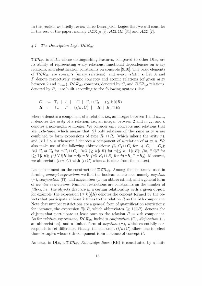
DLRifd is a DL whose distinguishing features, compared to other DLs, areits ability of representing n-ary relations, functional dependencies on n-aryrelations, and identification constraints on concepts [9,10]. The basic elementsof DLRifd are concepts (unary relations), and n-ary relations. Let A andP denote respectively atomic concepts and atomic relations (of given aritybetween 2 and nmax). DLRifd concepts, denoted by C, and DLRifd relations,denoted by R, , are built according to the following syntax rules:
C ::= >1 | A | ¬C | C1 u C2 | (≤ k [i]R)
R ::= >n | P | (i/n : C) | ¬R | R1 uR2
where i denotes a component of a relation, i.e., an integer between 1 and nmax,n denotes the arity of a relation, i.e., an integer between 2 and nmax, and kdenotes a non-negative integer. We consider only concepts and relations thatare well-typed, which means that (i) only relations of the same arity n arecombined to form expressions of type R1 u R2 (which inherit the arity n),and (ii) i ≤ n whenever i denotes a component of a relation of arity n. Wealso make use of the following abbreviations: (i) C1 t C2 for ¬(¬C1 u ¬C2);(ii) C1⇒C2 for ¬C1 t C2; (iii) (≥ k [i]R) for ¬(≤ k−1 [i]R); (iv) ∃[i]R for(≥ 1 [i]R); (v) ∀[i]R for ¬∃[i]¬R; (vi) R1 t R2 for ¬(¬R1 u ¬R2). Moreover,we abbreviate (i/n : C) with (i : C) when n is clear from the context.
Let us comment on the constructs of DLRifd . Among the constructs used informing concept expressions we find the boolean constructs, namely negation(¬), conjunction (u), and disjunction (t, an abbreviation), and a general formof number restrictions. Number restrictions are constraints on the number offillers, i.e., the objects that are in a certain relationship with a given object:for example, the expression (≥ k [i]R) denotes the concept formed by the ob-jects that participate at least k times to the relation R as the i-th component.Note that number restrictions are a general form of quantification restrictions:for instance, the expression ∃[i]R, which abbreviates (≥ 1 [i]R), denotes theobjects that participate at least once to the relation R as i-th component.As for relation expressions, DLRifd includes conjunction (u), disjunction (t,an abbreviation), and a limited form of negation (¬), which essentially cor-responds to set difference. Finally, the construct (i/n : C) allows one to selectthose n-tuples whose i-th component is an instance of concept C.
As usual in DLs, a DLRifd Knowledge Base (KB) is constituted by a finite
18

set of inclusion assertions. In DLRifd , these assertions have one of the forms:
R1 v R2 C1 v C2
with R1 and R2 of the same arity.
Besides inclusion assertions, DLRifd KBs allow for assertions expressing iden-tification constraints and functional dependencies. An identification assertionon a concept C has the form:
(id C [i1]R1, . . . , [ih]Rh)
where each Rj is a relation, and each ij denotes one component of Rj. Intu-itively, such an assertion states that no two different instances of C agree onthe participation to R1, . . . , Rh. More precisely, if a is an instance of C that isthe ij-th component of a tuple tj of Rj, for j ∈ {1, . . . , h}, and b is an instanceof C that is the ij-th component of a tuple sj of Rj, for j ∈ {1, . . . , h}, andfor each j, tj agrees with sj in all components different from ij, then a and bare the same object.
For example, the identification assertions (id Origin [1]call, [1]from) expressesthat each Origin of a call is uniquely determined by the (phone)-call and bythe phone from which the call was made.
A functional dependency assertion on a relation R has the form:
(fd R i1, . . . , ih → j)
where h ≥ 2, and i1, . . . , ih, j denote components of R. The assertion imposesthat two tuples of R that agree on the components i1, . . . , ih, agree also onthe component j.
For example, the functional dependency assertion (fd callLengthString 1, 2 → 3)expresses that the first two components of the ternary relation callLengthString
functionally determine the third component.
Note that unary functional dependencies (i.e., functional dependencies withh = 1) are ruled out in DLRifd , since these lead to undecidability of reason-ing [9]. Note also that the right hand side of a functional dependency containsa single element. However, this is not a limitation, because any functional de-pendency with more than one element in the right hand side can always besplit into several dependencies of the above form.
As usual in DLs, the semantics of DLRifd is specified through the notion ofinterpretation. An interpretation I = (∆I , ·I) of aDLRifd KBK is constitutedby an interpretation domain ∆I and an interpretation function ·I that assignsto each concept C a subset CI of ∆I and to each relation R of arity n a subset
19

>In ⊆ (∆I)n
P I ⊆ >In(i/n : C)I = {t ∈ >In | t[i] ∈ CI}
(¬R)I = >In \RI
(R1 uR2)I = RI1 ∩RI
2
>I1 = ∆I
AI ⊆ ∆I
(¬C)I = ∆I \ CI
(C1 u C2)I = CI1 ∩ CI
2
(≤ k [i]R)I = {a ∈ ∆I | ]{t ∈ RI1 | t[i] = a} ≤ k}
Fig. 15. Semantic rules for DLRifd (P , R, R1, and R2 have arity n)
RI of (∆I)n, such that the conditions in Figure 15 are satisfied. In the figure,t[i] denotes the i-th component of tuple t, and ]S denotes the cardinality ofthe set S. Observe that >1 denotes the interpretation domain, while >n, forn > 1, does not denote the n-Cartesian product of the domain, but only asubset of it that covers all relations of arity n. It follows, from this property,that the “¬” constructor on relations is used to express difference of relations,rather than complement.
To specify the semantics of a KB we first define when an interpretation satisfiesan assertion as follows:
• An interpretation I satisfies an inclusion assertion R1 v R2 (resp., C1 v C2)if RI
1 ⊆ RI2 (resp., CI
1 ⊆ CI2 ).
• An interpretation I satisfies the assertion (id C [i1]R1, . . . , [ih]Rh) if for alla, b ∈ CI and for all t1, s1 ∈ RI
1 , . . . , th, sh ∈ RIh we have that:
a = t1[i1] = · · · = th[ih],
b = s1[i1] = · · · = sh[ih],
tj[i] = sj[i], for j ∈ {1, . . . , h}, and for i 6= ij
implies a = b
• An interpretation I satisfies the assertion (fd R i1, . . . , ih → j) if for allt, s ∈ RI , we have that:
t[i1] = s[i1], . . . , t[ih] = s[ih] implies t[j] = s[j]
An interpretation that satisfies all assertions in a KB K is called a model ofK.
We say that a KB K is satisfiable if there exists a model of K. A concept C issatisfiable w.r.t. KB K if there is a model I of K such that CI is nonempty.An assertion α is logically implied by K if all models of K satisfy α. It canbe shown that all these reasoning tasks, namely KB satisfiability, conceptsatisfiability w.r.t. a KB, and logical implication, are mutually reducible (inpolynomial time).
20

One of the distinguishing features of DLs is that they have decidable reasoningtasks, i.e., they admit (terminating) reasoning procedures that are sound andcomplete with respect to the semantics. In particular, reasoning (i.e., KBsatisfiability, concept satisfiability w.r.t. a KB, and logical implication) inDLRifd is EXPTIME-complete [10,9].
DLRifd (as most DLs, including ALCQI – see later) has the tree-model prop-erty [10,9]. This means that, if a DLRifd KB admits a model, it also admitsa model which has the structure of a tree, where nodes are either objects or(reified) tuples, and edges connect tuples to their components. Observe that intree-like structures non-unary identification assertions and (non-unary) func-tional dependency assertions are trivially satisfied, since there cannot be twotuples agreeing on more than one component [9]. As a consequence we havethat a DLRifd KB is satisfiable if and only the same knowledge base withoutnon-unary identification and functional dependency assertions is satisfiable.Hence, logical implication of inclusion assertions can be verified without con-sidering identification and functional dependency assertions at all. This leadsus to consider simpler logics in which such assertions are not present.
4.2 The Description Logics ALCQI and ALC
ALCQI [35,36] is a rich DL in which knowledge is represented in terms ofconcepts (classes) and roles (binary relations). It can be seen as a fragmentof DLRifd where relations are restricted to be binary and KBs are restrictedto be a finite set of inclusion assertions on concepts only (no inclusion asser-tions on relations, and no identification assertions, and obviously no functionaldependency assertions since they require a relation of arity at least three).
Let A and P denote respectively atomic concepts and atomic roles (binaryrelations). ALCQI concepts, denoted by C, and ALCQI roles, denoted by R,are built according to the following syntax rules:
C ::= A | ¬C | C1 u C2 | (≤ k R.C)
R ::= P | P−
Additionally, we make use of the abbreviations below: (i) ⊥ for Au¬A (whereA is any atomic concept); (ii) > for ¬⊥; (iii) C1 tC2 for ¬(¬C1 u ¬C2); (iv)C1⇒C2 for ¬C1 t C2; (v) (≥ k R.C) for ¬(≤ k − 1 R.C); (vi) ∃R.C for(≥ 1 R.C); (vii) ∀R.C for ¬∃R.¬C.
An ALCQI KB is constituted by a finite set of inclusion assertions of theform C1 v C2, with C1 and C2 arbitrary concept expressions.
21

Notably ALCQI includes inverse roles P−, which allow for talking about theinverse of a relation, and qualified number restrictions, which are the mostgeneral form of cardinality constraints on roles. The semantics of ALCQIconstructs and KBs is analogous to that of DLRifd . In particular the semanticrules for inverse roles and qualified number restrictions are as follows:
(P−)I = {(a, a′) ∈ ∆I ×∆I | (a′, a) ∈ P I}(≤ k R.C)I = {a ∈ ∆I | ]{a′ ∈ ∆I | (a, a′) ∈ RI ∧ a′ ∈ CI} ≤ k}
We can define KB satisfiability, concept satisfiability w.r.t. a KB, and logi-cal implication, as for DLRifd . Moreover, as for DLRifd , reasoning (i.e., KBsatisfiability, concept satisfiability w.r.t. a KB, and logical implication) in aALCQI KB is EXPTIME-complete [35,36].
Finally we turn to ALC [37]. This is a simpler DL, obtained from ALCQI bydropping inverse roles and restricting qualified number restrictions to existen-tial restrictions only. The syntax of ALC concept is thus as follows:
C ::= A | ¬C | C1 u C2 | ∃P .C
We also introduce the standard abbreviations:
C1 t C2 for ¬(¬C1 u ¬C2)
∀P .C for ¬∃P .¬C
The semantics of the existential restrictions is
(∃P .C)I = {a ∈ ∆I | ∃b.(a, b) ∈ P I ∧ b ∈ CI}.
The semantics of the other constructs is as inALCQI. As forALCQI, anALCKB is a finite set of inclusion assertions on ALC concepts. In spite of its sim-plicity, reasoning in ALC KBs is EXPTIME-complete, as for ALCQI [38,39].
5 Hardness of reasoning on UML class diagrams
The reasoning tasks necessary for checking the various properties discussed inSection 3 are mutually reducible to each other. As an example, we show themutual reducibility between class consistency and class subsumption.
Given a class diagram with classes C1 and C2, if we want to check whetherC1 subsumes C2, then we can add to the class diagram the part depictedin Figure 16, where O, C, and C1 are new classes, and check whether C isinconsistent. Indeed, if C1 subsumes C2, there can be no object that is both in
22

O
{disjoint}
C1 C1 C2
C
Fig. 16. Reduction from class subsumption to class consistency
O
{disjoint}
C1 C1 C
C∅
Fig. 17. Reduction from class consistency to class subsumption
C1, hence not in C1, and in C2, and so C is inconsistent. Conversely, if C1 doesnot subsume C2, this means that there is a model I of the (original) diagramwith an object o not in C1 but in C2. We can take the extension of C1 in I toinclude o. Hence C has a nonempty extension in I and is consistent.
Given a class diagram with a class C, if we want to check whether C is incon-sistent, then we can add to the class diagram the part depicted in Figure 17,where O, C1, C1, and C∅ are new classes, and check whether C∅ subsumes C.Indeed, since C1 and C1 are disjoint, C∅ denotes the empty class, and so C isinconsistent if and only if it is subsumed by C∅.
Hence in the following, without loss of generality, we focus on class consistencyonly. Specifically, we show that class consistency in UML class diagrams isEXPTIME-hard, even when we use only binary associations, the only kind ofmultiplicities are of the form 0..∗ and 1..∗, and the only type of constraintsare disjointness and covering constraints. We prove the claim by a reductionfrom concept satisfiability in ALC KBs, which is EXPTIME-hard [38,39]. Weproceed in two steps:
(1) First, we show that we can restrict the attention to a syntactically re-stricted form of ALC called ALC− below.
(2) Then, we describe a reduction from atomic concept satisfiability in ALC−KBs to class consistency in UML class diagrams.
In the following, we call primitive an inclusion assertion of the form A v C,where A is an atomic concept and C is an arbitrary concept.
23

The DL ALC− is obtained from ALC by dropping intersection and allowingonly for complex concepts built with at most one construct of ALC, i.e.,
C ::= A | ¬A | A1 t A2 | ∃P .A | ∀P .A
where A denotes an atomic concept and P denotes an atomic role. An ALC−KB is a finite set of primitive ALC− inclusion assertions, i.e., inclusion asser-tions of the form A v C where C is an ALC− concept.
By exploiting a result in [40] we can reduce concept satisfiability in ALC KBsto atomic concept satisfiability in ALC− KBs.
Lemma 5.1 Concept satisfiability w.r.t. an ALC KB can be linearly reducedto atomic concept satisfiability w.r.t. a primitive ALC KB.
Proof. Let K be an ALC KB and C an ALC concept. By a result in [40],C is satisfiable w.r.t. K if and only if AT u C is satisfiable w.r.t. the KB K1
consisting of the single assertion
AT v uC1vC2∈K
(¬C1 t C2) u u1≤i≤n
∀Pi.AT
where AT is a new atomic concept and P1, . . . , Pn are all atomic roles appearingin K and C.
Then, in order to reduce the problem to atomic concept satisfiability, we in-troduce a new atomic concept AC , and check its satisfiability w.r.t. K2 =K1∪{AC v AT uC}. Indeed, if K1 admits a model I such that (AT uC)I 6= ∅,then by extending I so that AI
C = (AT u C)I , we get a model of K2 in whichAI
C 6= ∅. Conversely, every model of K2 with AIC 6= ∅ is also a model of K1
with (AT u C)I 6= ∅.
Below we assume, without loss of generality, that primitive ALC KBs are innegation normal form. Indeed, every primitive ALC KB can be rewritten innegation normal form in linear time.
Given a primitive ALC KB K (in negation normal form), we construct aprimitive ALC− KB K′ by recursively replacing each ALC assertion in K thatis not already a (primitive) ALC− assertion as follows:
(1) A v C1 u C2 is replaced by A v C1 and A v C2;(2) A v C1 t C2 is replaced by A v A1 t A2, A1 v C1 and A2 v C2, where
A1 and A2 are new atomic concepts;(3) A v ∀P .C is replaced by A v ∀P .A1 and A1 v C, where A1 is a new
atomic concept;(4) A v ∃P .C is replaced by A v ∃P .A1 and A1 v C, where A1 is a new
atomic concept.
24

Notice that the number of such replacements is finite (in fact linear), since foreach occurrence of an ALC construct in K at most one replacement is done.
Lemma 5.2 Given a primitive ALC KB K, the size of the (primitive) ALC−KB K′ obtained as above is linear in the size of K.
Proof. By construction.
Lemma 5.3 An atomic concept A0 is satisfiable w.r.t. a primitive ALC KBK if and only if A0 is satisfiable w.r.t. the (primitive) ALC− KB K′ obtainedas above.
Proof. We show that A0 is satisfiable w.r.t. K if and only if it is satisfiablew.r.t. the KB obtained after n replacements, for each n > 0. We proceed byinduction on n. Let Ki be the KB obtained from K after i replacements.
Base case: K0 = K (obvious).
Inductive case: By inductive hypothesis, we have that A0 is satisfiable w.r.t.K if and only if A0 is satisfiable w.r.t. Kn. We prove that, given a model Iof Kn with AI
0 6= ∅ we can construct a model J of Kn+1 with AJ0 6= ∅, and
conversely, that every model J of Kn+1 with AJ0 6= ∅ is also a model of Kn.
(1) If the next step to be applied is the replacement of A v C1 u C2 withA v C1 and A v C2, then:
Kn+1 = Kn ∪ {A v C1, A v C2} \ {A v C1 u C2}
In this case, the statement is obvious, since {A v C1 u C2} logicallyimplies {A v C1, A v C2} and vice-versa. Therefore Kn+1 and Kn havethe same models.
(2) If the next step consists in the replacement of A v C1tC2 by A v A1tA2,A1 v C1 and A2 v C2, where A1 and A2 are new atomic concepts, weget:
Kn+1 = Kn ∪ {A v A1 t A2, A1 v C1, A2 v C2} \ {A v C1 t C2}
“⇐” Let I be a model of Kn with AI0 6= ∅, let J coincide with I on
all atomic concepts and roles in Kn, and additionally let AJ1 = CI
1 andAJ
2 = CI2 . Since I satisfies A v C1 t C2, we have by construction that
J satisfies A v A1 t A2, A1 v C1 and A2 v C2, and hence is a model ofKn+1 with AJ
0 6= ∅.“⇒” Let J be a model of Kn+1 with AJ
0 6= ∅. Since it satisfies A vA1 t A2, for each instance a ∈ AJ , we have a ∈ AJ
1 or a ∈ AJ2 . In the
first case, by A1 v C1, we get a ∈ CJ1 ; in the second case, by A2 v C2,
we get a ∈ CJ2 . Therefore, J satisfies A v C1 tC2, and hence is a model
25

of Kn as well.(3) If the next step to be applied is to replace A v ∀P .C by A v ∀P .A1 and
A1 v C, where A1 is a new atomic concept, we have:
Kn+1 = Kn ∪ {A v ∀P .A1, A1 v C} \ {A v ∀P .C}
“⇐” Let I be a model of Kn with AI0 6= ∅, let J coincide with I on all
atomic concepts and roles in Kn, and additionally let AJ1 = CI . Since I
satisfies A v ∀P .C, we have by construction that J satisfies A v ∀P .A1
and A1 v C, and hence is a model of Kn+1 with AJ0 6= ∅.
“⇒” Let J be a model of Kn+1 with AJ0 6= ∅. Since it satisfies A v
∀P .A1, for each instance a ∈ AJ , if a is connected via role P to aninstance a′, then a′ ∈ AJ
1 . By A1 v C, we have that a′ ∈ CJ . ThereforeJ satisfies A v ∀P .C, and hence is a model of Kn as well.
(4) If the next step to be applied is to replace A v ∃P .C by A v ∃P .A1 andA1 v C, where A1 is a new atomic concept, we have:
Kn+1 = Kn ∪ {A v ∃P .A1, A1 v C} \ {A v ∃P .C}
“⇐” Let I be a model of Kn with AI0 6= ∅, let J coincide with I on all
atomic concepts and roles in Kn, and additionally let AJ1 = CJ . Since I
satisfies A v ∃P .C, we have by construction that J satisfies A v ∃P .A1
and A1 v C, and hence is a model of Kn+1 with AJ0 6= ∅.
“⇒” Let J be a model of Kn+1 with AJ0 6= ∅. Since it satisfies A v
∃P .A1, there exists an instance a ∈ AJ that is connected via role P toan instance a′ ∈ AJ
1 . By A1 v C, we have that a′ ∈ CJ . Therefore Jsatisfies A v ∃P .C, and hence is a model of Kn as well.
Next, we reduce concept satisfiability w.r.t. a primitive ALC− KB K′ to classconsistency in a UML class diagram D. For each atomic concept A in K′,we introduce a class A in D. Additionally, we add a class O that generalizes(possibly indirectly) all classes in D. O is also used to specify disjointnessamong classes (see later). For each atomic role P , we introduce an associationP (with related association class), involving the class O twice. Intuitively,using O in such a way, we do not constrain in any way the classes to which theinstances of the components of P may belong. More classes and associations,as well as generalizations between O and the new classes, are added below asneeded.
The assertions in the ALC− KB K′ are encoded in the class diagram as follows:
(1) For each assertion of the form A v B, we introduce a generalizationbetween the classes A and B (where A is the subclass).
26

O
{disjoint}
BA
Fig. 18. UML encoding of the assertion A v ¬B
A B1 B2
{complete}
B
Fig. 19. UML encoding of the assertion A v B1 tB2
O
{disjoint} P
A A B
PA PA
{complete}
Fig. 20. UML encoding of the assertion A v ∀P .B
O
P
A1..∗
B
PAB
Fig. 21. UML encoding of the assertion A v ∃P .B
(2) For each assertion of the form A v ¬B, we construct the hierarchy inFigure 18, exploiting the superclass O to express disjointness between Aand B.
(3) For each assertion of the form A v B1 t B2, we introduce an auxiliaryclass B, and construct the hierarchy in Figure 19. Intuitively, being Ba covering of B1 and B2, and A a subclass of B, it follows that A is asubclass of the union of B1 and B2.
(4) For each assertion of the form A v ∀P .B, we introduce a new class A
27

and two new binary associations PA and PA (with their associated classes)and we construct the portion of diagram in Figure 20, where A and A aredisjoint and there is a generalization with covering constraint between Pand its children PA and PA. Note that A and B are the components ofPA, whereas A and O are the components of PA. Intuitively, the diagramenforces that each instance of A participating to P is in fact participatingto PA, and hence associated via P to an instance of B.
(5) For each assertion of the form A v ∃P .B, we introduce a new binaryassociation PAB, with its associated class, and we construct the portionof diagram shown in Figure 21. Note the proper multiplicity constraint1..∗ on the participation of A to PAB. 14 Intuitively, this implies that foreach instance of A, there exists an instance of B related to it throughPAB, and hence through P .
Lemma 5.4 Given a primitive ALC− KB K′, the size of the UML class dia-gram D constructed as above is linear in the size of K′.
Proof. By construction.
Lemma 5.5 An atomic concept A is satisfiable w.r.t. an ALC− KB K′ if andonly if the class A is consistent in the UML class diagram D constructed asabove.
Proof. “⇐” Let J = (∆J , ·J ) be an instantiation for D (i.e., a model ofthe corresponding FOL assertions). We show that J is also a model of allassertions in K′.
(1) For each assertion of the form A v B in K′, there is a generalization inD between the child class A and the parent class B. Hence, J assigns anextension to A and B in such a way that AJ ⊆ BJ .
(2) For each assertion of the form A v ¬B in K′, we have in D the hierarchyshown in Fig. 18, characterized by a disjointness constraint between Aand B. J assigns to the classes A, B and O the sets AJ , BJ , OJ so thatAJ ⊆ OJ , BJ ⊆ OJ and AJ ∩ BJ = ∅. From the latter we have thatAJ ⊆ ∆J \BJ .
(3) Each assertion of the form A v B1 t B2 in K′ corresponds in D to thehierarchy shown in Fig. 19, characterized by a covering constraint amongB and its children B1 and B2. J assigns an extension to the classes A,B, B1 and B2 in such a way that AJ ⊆ BJ , and BJ = BJ
2 ∪BJ2 . Hence
we get AJ ⊆ BJ1 ∪BJ
2 .(4) Each assertion of the form A v ∀P .B in K′ corresponds, in D, to the
14 In fact, in the case where we also have the assertion A v ∀P .B for some B,instead of proceeding as in Figure 21, we can simply add the cardinality constraint1..∗ to the association PAB in Figure 20.
28

sub-diagram in Fig. 20. J assigns to the classes in such a diagram anextension in such a way that the following constraints are satisfied:
AJ ⊆ OJ
AJ ⊆ OJ
AJ ∩ AJ
= ∅BJ ⊆ OJ
PJ ⊆ OJ ×OJ
PJA⊆ A
J ×OJ
PJA ⊆ AJ ×BJ
PJA ⊆ PJ
PJA⊆ PJ
PJ ⊆ PJA ∪ PJ
A
From the constraints above, we get that PJA ∩ PJ
A= ∅. Therefore, if x ∈
AJ then for all x′ ∈ OJ if (x, x′) ∈ PJ then (x, x′) ∈ PJA and therefore
x′ ∈ BJ , i.e., AJ ⊆ {x ∈ OJ | ∀x′ ∈ OJ . (x, x′) ∈ PJ ⊃ x′ ∈ BJ }.(5) Each assertion of the form A v ∃P .B in K′ corresponds, in D, to the
sub-diagram shown in Fig. 21. J assigns to the classes in such a diagraman extension in such a way that the following constraints are satisfied:
AJ ⊆ OJ
BJ ⊆ OJ
PJ ⊆ OJ ×OJ
PJAB ⊆ PJ
PJAB ⊆ AJ ×BJ
and for each x ∈ AJ we have that ]{x′ ∈ ∆I | (x, x′) ∈ PJAB} ≥ 1
(mandatory participation constraint). From these we get that for eachx ∈ AJ there exists x′ ∈ OJ such that (x, x′) ∈ PJ and x′ ∈ BJ , i.e.,AJ ⊆ {x ∈ OJ | ∃x′ ∈ OJ (x, x′) ∈ PJ ∧ x′ ∈ BJ }.
“⇒” Let I = (∆I , ·I) be a model of K′ with AI 6= ∅. We show that it canbe seen as an instantiation of D, once we assign a suitable extension to theauxiliary classes and roles introduced in the construction of D. First, we defineOI = ∆I .
(1) For each assertion of the form A v B in K′, we have a generalizationbetween classes A and B in D. I assigns to concepts A and B in K′the subsets AI and BI of ∆I , such that AI ⊆ BI , and hence correctlycaptures the generalization between classes A and B in D.
(2) For each assertion of the form A v ¬B in K′, we have a fragment of Das in Fig. 18. I assigns to concepts A and B the subsets AI and BI of∆I , such that AI ⊆ ∆I \BI . Then we have that AI ⊆ OI , BI ⊆ OI andAI ∩BI = ∅, thus correctly capturing the fragment of D.
(3) For each assertion of the form A v B1 tB2 in K′, we have a fragment ofD as in Fig. 19. I assigns to concepts B1 and B2 the subsets BI
1 and BI2
29

of ∆I , respectively, and to A a subset of their union, i.e., AI ⊆ BI1 ∪BI
2 .Let us define BI = BI
1 ∪ BI2 . Then AI ⊆ BI , thus correctly capturing
the fragment of D.(4) For each assertion of the form A v ∀P .B in K′, we have a fragment of D
as in Figure 20. Let us define:
• AI
= ∆I \ AI
• P IA = {(x, x′) ∈ P I | x ∈ AI}
• P IA
= {(x, x′) ∈ P I | x ∈ AI}
Then, by AI ⊆ {x ∈ ∆I | ∀x′ ∈ ∆I. (x, x′) ∈ P I ⊃ x′ ∈ BI}, we get:
AI ⊆ OI
AI ⊆ OI
AI ∩ AI
= ∅BI ⊆ OI
P I ⊆ OI ×OI
P IA ⊆ AI ×BI
P I ⊆ P IA ∪ P I
A
P IA ⊆ P I
P IA⊆ P I
thus correctly capturing the fragment of D.(5) For each assertion of the form A v ∃P .B in K′, we have a fragment of D
as in Figure 21. Let us define P IAB = {(x, x′) ∈ P I | x ∈ AI}. Then, by
AI ⊆ {x ∈ ∆I | ∃x′ ∈ ∆I. (x, x′) ∈ P I ∧ x′ ∈ BI}, we get that for eachx ∈ AI we have ]{x′ ∈ ∆I | (x, x′) ∈ P I
AB} ≥ 1, and we have that suchan instantiation is correct for the fragment of D.
By Lemmata 5.1, 5.2, 5.3, 5.4, 5.5, and EXPTIME-hardness of reasoning inALC knowledge bases, we get our hardness result.
Theorem 5.6 Class consistency in UML class diagrams is EXPTIME-hard.
6 Upper Bounds for Reasoning on UML Class Diagrams
In this section we show that reasoning on UML class diagrams is decidable,and in fact EXPTIME-complete. To do so we show that we can polynomiallyencode UML class diagrams in DLRifd knowledge bases and that such anencoding precisely captures the FOL semantics of UML class diagrams. Hence,reasoning on such diagrams is reduced to reasoning on DLRifd knowledgebases, which is in EXPTIME.
30

6.1 Encoding of UML Class Diagrams in DLRifd
We now illustrate the encoding of UML class diagrams in DLRifd , discussingeach construct separately.
6.1.1 Classes
An UML class is represented by a DLRifd concept. Indeed, both UML classesand DLRifd concepts denote sets of objects.
To capture an attribute a of type T for a class C we use a DLRifd binaryrelation a, and we specify the type of the attribute with the assertion:
C v ∀[1](a⇒(2 : T ))
Such an assertion specifies that, for each instance c of the concept C, allobjects related to c by a, are instances of T . Note that an attribute name isnot necessarily unique in the whole diagram, and hence two different classescould have the same attribute, possibly of different types. This situation iscorrectly captured by the formalization in DLRifd . To specify a multiplicity[i..j] associated to the attribute we add the assertion:
C v (≥ i [1]a) u (≤ j [1]a)
Such an assertion specifies that each instance of C participates at least i timesand at most j times to relation a via component 1. If i = 0, i.e., the attributeis optional, we omit the first conjunct, and if j = ∗ we omit the secondone. Observe that, for attributes with multiplicity [0..∗], we omit the wholeassertion, and that, when the multiplicity is missing (i.e., [1..1] is assumed)the above assertion becomes:
C v ∃[1]a u (≤ 1 [1]a)
Letf(P1, . . . , Pm) : R
be an operation of a class C that has m parameters belonging to the classesP1, . . . , Pm respectively and a result belonging to R. We formalize such anoperation as a DLRifd relation, named fP1,...,Pm , of arity 1+m+1 among in-stances of the DLRifd concepts C,P1, . . . , Pm, R. On such a relation we enforcethe following assertions.
• An assertion imposing the correct types to the parameters:
fP1,...,Pm v (2 : P1) u · · · u (m + 1 : Pm)
31

• An assertion imposing that the invocation of the operation on a given objectwith given parameters determines in a unique way the result (i.e., the rela-tion corresponding to the operation is in fact a function from the invocationobject and the parameters to the result):
(fd fP1,...,Pm 1, . . . , m + 1 → m + 2)
In case the operation has no parameters (i.e., m = 0), instead of the abovefunctional dependency we make use of the assertion:
>1 v (≤ 1 [1]f)
The form of the above DLRifd assertions depends only on the number ofparameters, and not on the specific class for which the operation is defined,nor on the types of parameters and of the result.
• An assertion imposing the correct type of the result, when the operation isinvoked on instances of the class C:
C v ∀[1](fP1,...,Pm ⇒(m + 2 : R))
As discussed in Section 2, the chosen way of naming relations corresponding tooperations does not pose any difficulty in the formalization of overloading ofoperations within the same class, since an operation is represented in DLRifd
by a relation having as name the signature of the operation, which consistsnot only of the operation name but also of the parameter types. Observe thatthe formalization of operations in DLRifd allows one to have operations withthe same name or even with the same signature in two different classes. Asdiscussed in Section 2, overriding of operations may show up as a restrictionon the return type.
Example 6.1 The DLRifd assertions that capture the attributes of classphone in Figure 1 are:
Phone v ∀[1](number⇒(2 : String))
Phone v (≥ 1 [1]number)
Phone v ∀[1](brand⇒(2 : String))
Operation lastDialed() is captured by the DLRifd assertions:
Phone v ∀[1](lastDialed)⇒(2 : String)
>1 v (≤ 1 [1]lastDialed)
32
Operation callLength(String) is captured by the DLRifd assertions:
callLengthString v (2 : String)
(fd callLengthString 1, 2 → 3)
Phone v ∀[1](callLengthString⇒(3 : Int))
¤
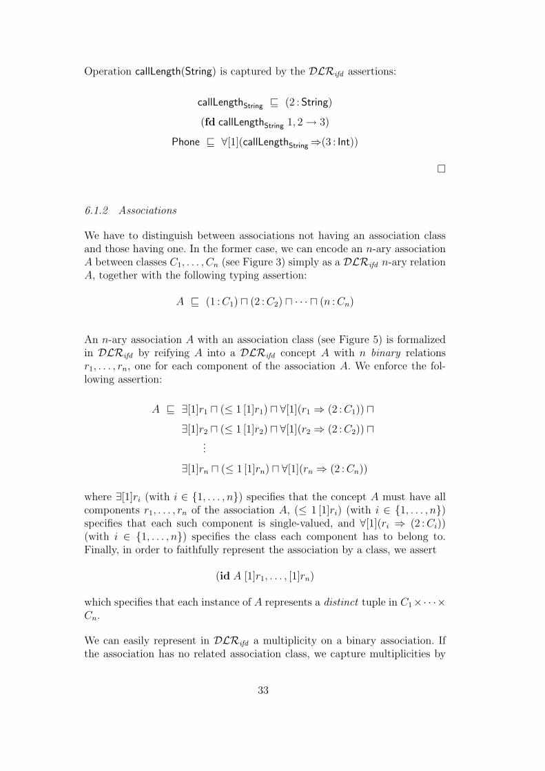
6.1.2 Associations
We have to distinguish between associations not having an association classand those having one. In the former case, we can encode an n-ary associationA between classes C1, . . . , Cn (see Figure 3) simply as a DLRifd n-ary relationA, together with the following typing assertion:
A v (1 : C1) u (2 : C2) u · · · u (n : Cn)
An n-ary association A with an association class (see Figure 5) is formalizedin DLRifd by reifying A into a DLRifd concept A with n binary relationsr1, . . . , rn, one for each component of the association A. We enforce the fol-lowing assertion:
A v ∃[1]r1 u (≤ 1 [1]r1) u ∀[1](r1 ⇒ (2 : C1)) u∃[1]r2 u (≤ 1 [1]r2) u ∀[1](r2 ⇒ (2 : C2)) u
...
∃[1]rn u (≤ 1 [1]rn) u ∀[1](rn ⇒ (2 : Cn))
where ∃[1]ri (with i ∈ {1, . . . , n}) specifies that the concept A must have allcomponents r1, . . . , rn of the association A, (≤ 1 [1]ri) (with i ∈ {1, . . . , n})specifies that each such component is single-valued, and ∀[1](ri ⇒ (2 : Ci))(with i ∈ {1, . . . , n}) specifies the class each component has to belong to.Finally, in order to faithfully represent the association by a class, we assert
(id A [1]r1, . . . , [1]rn)
which specifies that each instance of A represents a distinct tuple in C1×· · ·×Cn.
We can easily represent in DLRifd a multiplicity on a binary association. Ifthe association has no related association class, we capture multiplicities by
33

the following DLRifd assertions (referring to Figure 2):
C1 v (≥ n` [1]A) u (≤ nu [1]A)
C2 v (≥ m` [2]A) u (≤ mu [2]A)
Example 6.2 The DLRifd assertions that capture the aggregation 15 in Fig-ure 8, are:
reference v (1 : PhoneBill) u (2 : PhoneCall)
PhoneBill v (≥ 1 [1]reference)
PhoneCall v (≥ 1 [2]reference) u (≤ 1 [2]reference)
¤
If, instead, the association has a related class, we can impose a number restric-tion on the relations modeling the components of the association. Since thenames of such relations (which correspond to roles) are unique with respectto the association only, and not with respect to the entire diagram, we haveto state such constraints in DLRifd as follows (referring to Figure 4):
C1 v (≥ n` [2](r1 u (1 : A))) u (≤ nu [2](r1 u (1 : A)))
C2 v (≥ m` [2](r2 u (1 : A))) u (≤ mu [2](r2 u (1 : A)))
Example 6.3 The DLRifd assertions modeling the association in Figure 6are:
Origin v ∀[1](call⇒(2 : PhoneCall)) u ∃[1]call u (≤ 1 [1]call) u∀[1](from⇒(2 : Phone)) u ∃[1]from u (≤ 1 [1]from)
(id Origin [1]call, [1]from)
PhoneCall v (≥ 1 [2](call u (1 : Origin))) u (≤ 1 [2](call u (1 : Origin)))
Origin v ∀[1](place⇒(2 : String))
Origin v ∃[1]place u (≤ 1 [1]place)
¤
15 Recall that an aggregation is a special case of binary association without associ-ation class.
34

6.1.3 Generalizations and hierarchies
Generalization is naturally supported in DLRifd . If a UML class C2 generalizesa class C1, we can express this by the DLRifd assertion:
C1 v C2
Inheritance between DLRifd concepts corresponds exactly to inheritance be-tween UML classes. This is an obvious consequence of the semantics of v,which is based on sub-setting. Observe that the encoding in DLRifd also cap-tures correctly inheritance among association classes and multiple inheritancebetween classes.
A class hierarchy as the one in Figure 9 can be represented by the assertions
Ci v C for each i ∈ {1, . . . , n}
A disjointness constraint among classes C1, . . . , Cn can be formalized as
Ci vnu
j=i+1¬Cj for each i ∈ {1, . . . , n}
while a covering constraint can be expressed as
C vn⊔
j=1
Cj
Example 6.4 The hierarchy in Figure 10 can be formalized by means of thefollowing DLRifd assertions:
CellPhone v Phone
FixedPhone v Phone
CellPhone v ¬FixedPhone
Phone v CellPhone t FixedPhone
¤
If needed, one can easily add DLRifd assertions to state that all classes thatare not in the same hierarchy are a priori disjoint, and that objects in thesame hierarchy must belong to a most specific class.
Example 6.5 Finally, we show in Figure 22 how the UML class diagram inFigure 12 can be encoded in DLRifd .
¤
35

Origin v ∀[1](place⇒(2 : String))
Origin v ∃[1]place u (≤ 1 [1]place)
Origin v ∀[1](call⇒(2 : PhoneCall)) u ∃[1]call u (≤ 1 [1]call) u∀[1](from⇒(2 : Phone)) u ∃[1]from u (≤ 1 [1]from)
(id Origin [1]call, [1]from)
MobileOrigin v ∀[1](call⇒(2 : MobileCall)) u ∃[1]call u (≤ 1 [1]call) u∀[1](from⇒(2 : CellPhone)) u ∃[1]from u (≤ 1 [1]from)
(id MobileOrigin [1]call, [1]from)
PhoneCall v (≥ 1 [2](call u (1 : Origin))) u (≤ 1 [2](call u (1 : Origin)))
reference v (1 : PhoneBill) u (2 : PhoneCall)
PhoneBill v (≥ 1 [1]reference)
PhoneCall v (≥ 1 [2]reference) u (≤ 1 [2]reference)
MobileCall v PhoneCall
MobileOrigin v Origin
CellPhone v Phone
FixedPhone v Phone
CellPhone v ¬FixedPhone
Phone v CellPhone t FixedPhone
Fig. 22. DLRifd knowledge base corresponding to the UML class diagram shown inFigure 12
6.2 Correctness of the Encoding
We now show that the encoding presented above is indeed correct. In partic-ular, we show that there is a direct correspondence between instantiations ofthe UML class diagram and models of the corresponding DLRifd knowledgebase. This is captured by the following theorem.
Theorem 6.6 Let D be a UML class diagram and KD the DLRifd knowledgebase constructed as described above. Then every instantiation of D is a modelof KD, and vice-versa.
Proof. First of all, we observe that both (the FOL formalization of) the UMLclass diagram D and the DLRifd knowledge base KD are over the same alpha-
36

bet. So interpretations are compatible. Considering each UML class diagramconstruct separately, it is easy to see that an interpretation satisfies its FOLformalization if and only if it satisfies the corresponding DLRifd assertions.We show this in some detail below, also to make apparent the very closecorrespondence between the two formalizations.
• Class attributes. An attribute a of type T of the class C with multiplicity[i..j] is captured in D by the FOL assertions:
∀x, y. (C(x) ∧ a(x, y)) ⊃ T (y)
∀x, y. C(x) ⊃ i ≤ ]{y | a(x, y)} ≤ j
The corresponding DLRifd assertions in KD are
C v ∀[1](a⇒(2 : T ))
C v (≥ i [1]a) u (≤ j [1]a)
Now, given an instantiation I for D, each x ∈ CI is such that x is connectedthrough the binary relation aI only to elements of T I , and x participates atleast i and at most j times to aI . Hence I satisfies the DLRifd assertionsabove. Conversely, given a model I of KD, it is easy to see that each x ∈ CI
is connected through the binary relation aI only to elements of T I , and xparticipates at least i and at most j times to aI . Therefore, I satisfies theFOL formulas above.
• Class operations. An operation f(P1, . . . , Pm) : R of class C is expressed bythe FOL assertions: 16
∀x, p1, . . . , pm, r. f(x, p1, . . . , pm, r) ⊃ ∧ni=1 Pi(pi)
∀x, p1, . . . , pm, r, r′. f(x, p1, . . . , pm, r) ∧ f(x, p1, . . . , pm, r′) ⊃ r = r′
∀x, p1, . . . , pm, r. C(x) ∧ f(x, p1, . . . , pm, r) ⊃ R(r)
The corresponding DLRifd assertions in KD are
fP1,...,Pm v (2 : P1) u · · · u (m + 1 : Pm)
(fd fP1,...,Pm 1, . . . , m + 1 → m + 2)
C v ∀[1](fP1,...,Pm ⇒(m + 2 : R))
Given an instantiation I for D, it is such that for each x ∈ CI , if x partici-pates to y ∈ fI as first component, the components 2, . . . ,m+2 of y belong
16 To simplify the notation, we again denote fP1,...,Pm simply by f .
37

to P I1 , . . . , P I
m, R respectively, and the component m + 2 is uniquely deter-mined by the first m + 1. Hence I satisfies the DLRifd assertions above.Conversely, by the inclusion assertion, a model I of KD is such that forany x ∈ CI , if x participates to y ∈ fIP1,...,Pm
, the components 2, . . . ,m + 2of y belong to P I
1 , . . . , P Im, R respectively. Moreover, by the functional de-
pendency, the component m + 2 is uniquely determined by the first m + 1.Therefore, I satisfies the FOL formulas above.
• Associations without association class. Typing of an n-ary association Awithout association class is captured in D by the FOL assertion:
∀x1, . . . , xn. A(x1, . . . , xn) ⊃ C1(x1) ∧ · · · ∧ Cn(xn).
The corresponding DLRifd assertion in KD is
A v (1 : C1) u (2 : C2) u · · · u (n : Cn)
Given an instantiation I for D, we have that for any x ∈ AI , the compo-nents of x belong to CI
1 , . . . , CIn respectively. Hence I satisfies the DLRifd
assertion above. Conversely, given an interpretation I for KD, the DLRifd
assertion above requires that for any x ∈ AI , the components of x belongto CI
1 , . . . , CIn respectively. Therefore I satisfies the FOL formula above.
Multiplicities of a binary associations without association class are ex-pressed by the FOL assertions:
∀x. C1(x) ⊃ (n` ≤ ]{y | A(x, y)} ≤ nu)
∀y. C2(y) ⊃ (m` ≤ ]{x | A(x, y)} ≤ mu)
The corresponding DLRifd assertions in KD are
C1 v (≥ n` [1]A) u (≤ nu [1]A)
C2 v (≥ m` [2]A) u (≤ mu [2]A)
Again, considering the semantics of the assertions in FOL and in DLRifd ,it is immediate to verify that they are satisfied by exactly the same models.
• Associations with association class. An n-ary association A with associationclass is formalized in D by the following FOL assertions:
∀x, y. A(x) ∧ ri(x, y) ⊃ Ci(y) for i = 1, . . . , n
∀x. A(x) ⊃ ∃y. ri(x, y) for i = 1, . . . , n
∀x, y, y′. A(x) ∧ ri(x, y) ∧ ri(x, y′) ⊃ y = y′ for i = 1, . . . , n
∀y1, . . . , yn, x, x′. A(x) ∧ A(x′) ∧ ∧ni=1(ri(x, yi) ∧ ri(x
′, yi)) ⊃ x = x′
38

The corresponding DLRifd assertions in KD are
A v ∃[1]r1 u (≤ 1 [1]r1) u ∀[1](r1 ⇒ (2 : C1)) u∃[1]r2 u (≤ 1 [1]r2) u ∀[1](r2 ⇒ (2 : C2)) u
...
∃[1]rn u (≤ 1 [1]rn) u ∀[1](rn ⇒ (2 : Cn))
(id A [1]r1, . . . , [1]rn)
Given an instantiation I for D, by the FOL assertion above, we have thatfor each x ∈ AI , x participates exactly once as first component to each ofthe binary relations rIi , and x is connected through rI1 , . . . , rIn to elementsof CI
1 , . . . , CIn respectively; moreover, no two instances of AI can agree on
the participation to rI1 , . . . , rIn. Hence I satisfies all the DLRifd assertionsabove. Similarly, it is easy to see that a model I of KD, which has to satisfythe DLRifd assertions above, satisfies the corresponding FOL assertions aswell.
Multiplicities of a binary association A with association class are ex-pressed by the FOL assertions:
∀y1. C1(y1) ⊃ (n` ≤ ]{x | A(x) ∧ r1(x, y1)} ≤ nu)
∀y2. C2(y2) ⊃ (m` ≤ ]{x | A(x) ∧ r2(x, y2)} ≤ mu)
The corresponding DLRifd assertions in KD are
C1 v (≥ n` [2](r1 u (1 : A))) u (≤ nu [2](r1 u (1 : A)))
C2 v (≥ m` [2](r2 u (1 : A))) u (≤ mu [2](r2 u (1 : A)))
Again, considering the semantics of the assertions in FOL and in DLRifd ,it is immediate to verify that they are satisfied by exactly the same models.
• Generalizations. The generalization between a more general class C a morespecific class C1 is formalized by the FOL assertion:
∀x. C1(x) ⊃ C(x)
The corresponding DLRifd assertion in KD is:
C1 v C
Considering the semantics of such assertions, it is immediate to verify thatthey are satisfied by exactly the same models. It is also immediate to verifythat the FOL and DLRifd assertions expressing covering constraints anddisjointness constraints on class hierarchies are satisfied by exactly the samemodels.
39

A consequence of the above result is that reasoning on UML class diagramscan be performed by reasoning on DLRifd knowledge bases. In particular, thefollowing result holds.
Theorem 6.7 Let D be a UML class diagram and KD the DLRifd knowledgebase constructed as described above. Then a class C is consistent in D if andonly if the concept C is satisfiable w.r.t. KD.
Proof. The claim is a straightforward consequence of Theorem 6.6.
Since we can reduce reasoning on UML class diagrams to reasoning on DLRifd
knowledge bases, from the results about reasoning in DLRifd [9] we get anEXPTIME upper bound for reasoning on UML class diagrams.
Theorem 6.8 Class consistency in UML class diagrams is EXPTIME-complete.
Proof. Theorem 5.6 gives us the EXPTIME-hardness. The completeness fol-lows from Theorem 6.7, by considering that the size of KD is polynomial in Dand that concept satisfiability w.r.t. DLRifd knowledge bases is EXPTIME-complete [9].
7 Reasoning on UML Class Diagrams using ALCQI
The results in the previous section show that we can exploit reasoning toolsdeveloped for DLs to reason on UML class diagrams. However, current state-of-the-art DL based reasoning systems do not support yet all constructs ofDLRifd . In particular, they do not support functional dependencies and iden-tification constraints. In this section we show that, as far as reasoning on UMLclass diagrams is concerned (cf., Section 3), we can resort to a less expressiveDL, namely ALCQI, for which tableaux based reasoning algorithms havebeen developed [41,30]. State-of-the-art DL based reasoning systems [18,19]implement such tableaux algorithms, which allows them to be exploited ascore engines for advanced UML CASE tools. For an example of the kind ofservices that such a tool could provide, see [17]. Notably, ALCQI does notinclude functional dependencies and identification constraints, which play aspecial role, since they allow us to correctly capture the FOL semantics ofn-ary associations and of operations.
Interestingly, due to the tree-model property of DLRifd (cf., Section 4), whenwe do not want to specifically reason about functional dependencies or iden-
40

tification constraints, which is the case for most of the UML reasoning tasks(cf. Section 3), we can drop such constraints from DLRifd knowledge bases,while still preserving soundness and completeness of reasoning on conceptsand relations [9]. Another potential difficulty is that, in ALCQI, relations areonly binary, while DLRifd admits relations of arbitrary arity. We overcomethis difficulty by translating a DLRifd relation of arity n > 2 through reifica-tion: this is done by introducing a concept, denoting the tuples of the relation,and n ALCQI (binary) functional roles, one for each component of the rela-tion. The tree-model property guarantees that such a translation is faithful,in the sense that there will be no two instances of the concept representingthe same tuple of the relation [34].
7.1 Encoding of UML Class Diagrams in ALCQI
Building on these observations we now present an encoding of UML classdiagrams directly in ALCQI that, although it does not preserve models, issound and complete with respect to the main reasoning tasks on UML classdiagrams.
7.1.1 Classes
An UML class C is represented by an atomic concept C. Each attribute aof type T for class C is represented by an atomic role a, together with aninclusion assertion encoding the typing of the attribute a for the class C:
C v ∀a.T
We formalize the multiplicity [i..j] of attribute a as
C v (≥ i a.>) u (≤ j a.>)
expressing that for each instance of the concept C there are at least i andat most j role fillers for role a. As we did for DLRifd , for attributes withmultiplicity [0..∗] we omit the whole assertion, and when the multiplicity ismissing (i.e., [1..1] is assumed) the above assertion becomes:
C v ∃a.> u (≤ 1 a.>)
An operation f() : R without parameters for class C is modeled directly as a(binary) role Rf(), for which the following assertion holds:
C v ∀Rf().R u (≤ 1 Rf().>)
41

Instead, an operation with one or more parameters f(P1, . . . , Pm) : R of classC, which formally corresponds to an (m + 2)-ary relation that is functionalon the last component, cannot be directly expressed in ALCQI. Therefore,we make use of reification, and introduce an atomic concept Cf(P1,...,Pm), m+2ALCQI roles r1, . . . , rm+2 and the following assertions, which type the inputparameters and the return value:
Cf(P1,...,Pm) v ∃r1.> u (≤ 1 r1.>) u...
∃rm+1.> u (≤ 1 rm+1.>)
Cf(P1,...,Pm) v ∀r2.P1 u · · · u ∀rm+1.Pm
C v ∀r−1 .(Cf(P1,...,Pm)⇒∀rm+2.R)
The first assertion states that each instance of Cf(P1,...,Pm), representing a tuple,correctly is connected to exactly one object for each of the roles r1, . . . , rm+1.Instead, note that in general there may be two instances of Cf(P1,...,Pm) repre-senting the same tuple. However, this cannot be the case in a tree-like model(cf., tree-model property). The other two assertions impose the correct typingof the parameters, depending only on the name of the operation, and of thereturn value, depending also on the class.
7.1.2 Associations
Each binary association (or aggregation) A between a class C1 and a class C2
is represented by the atomic role A, together with the inclusion assertion
> v ∀A.C2 u ∀A−.C1
encoding the typing of A. The multiplicities of A (see Figure 2) are formalizedby the assertions
C1 v (≥ n` A.>) u (≤ nu A.>)
C2 v (≥ m` A−.>) u (≤ mu A−.>)
Binary associations with association class, and n-ary (with n > 2) associa-tions, with or without association class, are modeled through reification. Moreprecisely, each association A relating classes C1, . . . , Cn is represented by anatomic concept A together with the inclusion assertion
A v ∃r1.C1 u · · · u ∃rn.Cn u (≤ 1 r1) u · · · u (≤ 1 rn)
42

If the association A has explicit role names in the UML class diagram, thenr1, . . . , rn above are such names. Otherwise, they are arbitrary names used todenote the components of A. As we did for operations, we are not requiringthat each instance of the concept A denotes a distinct tuple, but again this isthe case in tree-like models.
Multiplicities on binary associations with association class (see Figure 4) arerepresented by
C1 v (≥ n` r−1 .A) u (≤ nu r−1 .A)
C2 v (≥ m` r−2 .A) u (≤ mu r−2 .A)
7.1.3 Generalizations
Generalizations between classes, and disjointness and covering constraints onhierarchies are expressed in ALCQI as they are in DLRifd . In particular, ageneralization between a class C and its child class C1 can be represented usingthe ALCQI inclusion assertion C1 v C. A class hierarchy as the one in Fig-ure 9 can be represented by the assertions C1 v C, . . . , Cn v C. A disjointnessconstraint among classes C1, . . . , Cn can be modeled as Ci v un
j=i+1¬Cj, with1 ≤ i ≤ n− 1, while a covering constraint can be expressed as C v tn
i=1Ci.
Example 7.1 We show in Figure 23 the ALCQI knowledge base correspond-ing to the UML class diagram in Figure 12. ¤
7.2 Correctness of the Encoding
We now show that the encoding of a UML class diagram into an ALCQIknowledge base is correct, in the sense that it preserves class consistency, andhence essentially all reasoning services over UML class diagrams. Formally,the following result holds.
Theorem 7.2 Let D be a UML class diagram and KD the ALCQI knowledgebase constructed as specified above. Then a class C is consistent in D if andonly if the concept C is satisfiable w.r.t. KD.
Proof. “⇒” Let I = (∆I , ·I) be an instantiation of D (i.e., a model of thecorresponding FOL assertions) such that CI 6= ∅. Then we can build a modelJ = (∆J , ·J ) of KD such that CJ 6= ∅ as follows.
• ∆J = ∆I∪⋃A∈A{t(d1,...,dn) | (d1, . . . , dn) ∈ AI}∪⋃
F∈F{t(d1,...,dn) | (d1, . . . , dn) ∈F I}, where A denotes the set of all non-binary associations without asso-ciation class in D, and F denotes all functional relations that model class
43

Origin v ∀place.String
Origin v ∃place.> u (≤ 1 place)
Origin v ∃call.PhoneCall u (≤ 1 call) u∃from.Phone u (≤ 1 from)
MobileOrigin v ∃MobileCall.MobileCall u (≤ 1 MobileCall) u∃from.CellPhone u (≤ 1 from)
PhoneCall v (≥ 1 call−.Origin) u (≤ 1 call−.Origin)
> v ∀reference−.PhoneBill u ∀reference.PhoneCall
PhoneBill v (≥ 1 reference−)
PhoneCall v (≥ 1 reference) u (≤ 1 reference)
MobileCall v PhoneCall
MobileOrigin v Origin
CellPhone v Phone
FixedPhone v Phone
CellPhone v ¬FixedPhone
Phone v CellPhone t FixedPhone
Fig. 23. ALCQI knowledge base corresponding to the UML class diagram shown inFigure 12
operations.• CJ = CI for all concepts C corresponding to classes C in D.• RJ = RI for all ALCQI roles R corresponding to attributes, operations
without parameters, aggregations, binary associations without associationclass, and association class roles in D.
• For each operation f(P1, . . . , Pm) : R with one or more parameters, wedefine CJf(P1,...,Pm) = {t(d0,d1,...,dm+1) | (d0, d1, . . . , dm+1) ∈ fI(P1,...,Pm)}, and foreach ALCQI role ri modeling the i-th component of the relation f(P1,...,Pm),we define rJi = {(t(d0,d1,...,dm+1), di) | (d0, d1, . . . , dm+1) ∈ fI(P1,...,Pm)}.
• Finally, for each n-ary association A with arity n > 2 and without asso-ciation class, we define AJ = {t(d1,...,dn) | d1, . . . , dn ∈ AI} and for eachALCQI role ri modeling the i-th component of the association A, we definerJi = {(t(d1,...,dn), di) | (d1, . . . , dn) ∈ AI}.
Trivially CJ = CI 6= ∅. It is also immediate to check that J satisfies all theassertions in KD. Again one can proceed by focusing on the assertions that
44

each kind of UML class diagram construct gives rise to.
As an example, we detail the proof for operations, since proving the statementin this case is less straightforward than in all the others cases. An operationf(P1, . . . , Pm) : R of a class C in the diagram D is represented by the FOLformulas:
∀x, p1, . . . , pm, r. f(x, p1, . . . , pm, r) ⊃ ∧mi=1 Pi(pi)
∀x, p1, . . . , pm, r, r′. f(x, p1, . . . , pm, r) ∧ f(x, p1, . . . , pm, r′) ⊃ r = r′
∀x, p1, . . . , pm, r. C(x) ∧ f(x, p1, . . . , pm, r) ⊃ R(r)
that correspond to the ALCQI assertions:
Cf(P1,...,Pm) v ∃r1.> u (≤ 1 r1.>) u...
∃rm+2.> u (≤ 1 rm+2.>)
Cf(P1,...,Pm) v ∀r2.P1 u · · · u ∀rm+1.Pm
C v ∀r−1 .(Cf(P1,...,Pm)⇒∀rm+2.R)
Given an instantiation I of D, for all y ∈ fI , the components 2, . . . , m + 1 ofy belong to P I
1 , . . . , P Im, and for all x ∈ CI if x participates as first component
to y ∈ fI , the component m + 2 of y belongs to RI . Additionally, the firstm + 1 components uniquely determine the component m + 2.
The interpretation J , built from I as shown above, instantiates the con-cept Cf(P1,...,Pm), which models f(P1, . . . , Pm) : R, with the (m + 2)-tuples offI(P1,...,Pm), and instantiates each role ri with pairs where the first component is
a tuple (d0, d1, . . . , dm+1) of fI(P1,...,Pm) and the second one is the component di
of (d0, d1, . . . , dm+1) to which ri refers. In particular, each tuple of ri connectseach element of Cf(P1,...,Pm) to the element of the correct type (and only toit) and no two elements of Cf(P1,...,Pm) represent the same tuple. Hence, J itsatisfies the above ALCQI assertions.
“⇐” By the tree-model property we know that if C is satisfiable w.r.t. theALCQI knowledge base KD then there exists a tree-like model J = (∆J , ·J )of KD, such that CJ 6= ∅. From such a tree-like model we can build aninstantiation I = (∆I , ·I) of D such that CI 6= ∅ as follows.
• ∆I =⋃
C∈C CJ , where C denotes the set of all classes in D.• CI = CJ for all classes C in D.• RI = RJ for all attributes, operations without parameters, aggregations,
binary associations without association class, and association class roles in
45
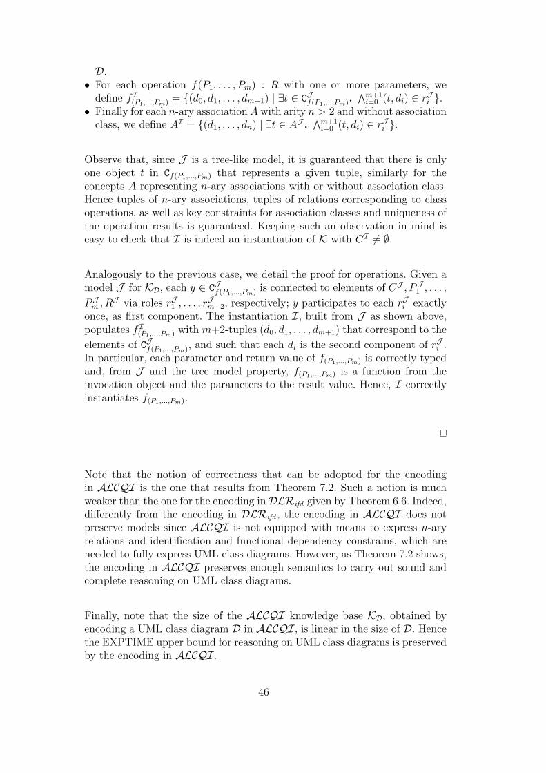
D.• For each operation f(P1, . . . , Pm) : R with one or more parameters, we
define fI(P1,...,Pm) = {(d0, d1, . . . , dm+1) | ∃t ∈ CJf(P1,...,Pm).∧m+1
i=0 (t, di) ∈ rJi }.• Finally for each n-ary association A with arity n > 2 and without association
class, we define AI = {(d1, . . . , dn) | ∃t ∈ AJ .∧m+1
i=0 (t, di) ∈ rJi }.
Observe that, since J is a tree-like model, it is guaranteed that there is onlyone object t in Cf(P1,...,Pm) that represents a given tuple, similarly for theconcepts A representing n-ary associations with or without association class.Hence tuples of n-ary associations, tuples of relations corresponding to classoperations, as well as key constraints for association classes and uniqueness ofthe operation results is guaranteed. Keeping such an observation in mind iseasy to check that I is indeed an instantiation of K with CI 6= ∅.
Analogously to the previous case, we detail the proof for operations. Given amodel J for KD, each y ∈ CJf(P1,...,Pm) is connected to elements of CJ , PJ
1 , . . . ,
PJm , RJ via roles rJ1 , . . . , rJm+2, respectively; y participates to each rJi exactly
once, as first component. The instantiation I, built from J as shown above,populates fI(P1,...,Pm) with m+2-tuples (d0, d1, . . . , dm+1) that correspond to the
elements of CJf(P1,...,Pm), and such that each di is the second component of rJi .In particular, each parameter and return value of f(P1,...,Pm) is correctly typedand, from J and the tree model property, f(P1,...,Pm) is a function from theinvocation object and the parameters to the result value. Hence, I correctlyinstantiates f(P1,...,Pm).
Note that the notion of correctness that can be adopted for the encodingin ALCQI is the one that results from Theorem 7.2. Such a notion is muchweaker than the one for the encoding in DLRifd given by Theorem 6.6. Indeed,differently from the encoding in DLRifd , the encoding in ALCQI does notpreserve models since ALCQI is not equipped with means to express n-aryrelations and identification and functional dependency constrains, which areneeded to fully express UML class diagrams. However, as Theorem 7.2 shows,the encoding in ALCQI preserves enough semantics to carry out sound andcomplete reasoning on UML class diagrams.
Finally, note that the size of the ALCQI knowledge base KD, obtained byencoding a UML class diagram D in ALCQI, is linear in the size of D. Hencethe EXPTIME upper bound for reasoning on UML class diagrams is preservedby the encoding in ALCQI.
46

7.3 Description Logics Reasoners
Current state-of-the-art DL reasoning systems [18,19,42] support arbitrarycomplex ALCQI knowledge bases and implement sound and complete rea-soning algorithms. These algorithms are based on tableaux techniques [43]and, although not optimal from the computational complexity point of view,are highly optimized and exhibit good average case performance [44].
Two of the best-known systems are FaCT 17 , developed at the University ofManchester [18,41,29] and Racer 18 , developed at the Hamburg Universityof Science and Technology [19,45]. Both these systems perform a preliminaryclassification (see [46]) of the concepts of the ALCQI knowledge base. Clas-sification iteratively computes, by subsequent subsumption tests, a taxonomyof classes, making explicit all subsumption relationships among the conceptsof the knowledge base. Once this classification step is performed, reasoningservices can take advantage of it to speed up inferences.
Encoding a UML class diagram in an ALCQI knowledge base allows thedesigner of the diagram for exploiting the reasoning services offered by DLreasoners. In such a way, relevant properties of the diagram can be formallyverified, as discussed in Section 3. Indeed, classification builds a hierarchy ofthe (concepts corresponding to the) UML classes belonging to the diagram.This hierarchy reflects the various constraints that the diagram enforces on theclasses, as well as their properties and the relations among them. In the nextsection, we apply these ideas to an application domain of industrial interest.
8 A Case Study
In the previous section we showed that UML class diagrams can be encodedas ALCQI knowledge bases preserving enough semantics to keep reasoningsound and complete. On the other handALCQI is a DL that can be dealt withby current state-of-the-art DL-based systems. Hence these systems could serveas a core reasoning engine in advanced CASE tools equipped with automatedreasoning capabilities on UML class diagrams. In order to verify such an idea,we did some experimentation both on UML class diagrams developed for ed-ucational purposes, and on UML class diagrams of industrial interest [47,48].In this section we give a brief overview of the latter experience with an indus-trial scale example, namely, the UML class diagrams forming the CommonInformation Model.
17 http://www.cs.man.ac.uk/~horrocks/FaCT/18 http://www.sts.tu-harburg.de/~r.f.moeller/~racer/
47

Common Information Model (CIM) 19 is a model defined by the DistributedManagement Task Force (DMTF), with the purpose of providing a rigorous ap-proach for modeling systems and networks using the object-oriented paradigm.CIM has a Meta Schema, expressed as a set of UML class diagrams that formthe basis of a sort of vocabulary for analyzing and describing managed systems.According to the particular needs of a given application, such schemas can beextended through subclassing to include aspects specific to the application.CIM offers three main conceptual schemas, each expressed as a UML classdiagram: the Core Model, the Common Model and the Extension Schemas.The Core Model and the Common Model together form the CIM Schema.
• The Core Model is an information model capturing basic notions that areapplicable to all areas of management (e.g., logical device or system com-ponent).
• The Common Model is an information model that expresses concepts re-lated to specific management areas, but still independent of a particulartechnology or implementation. The common areas defined in the CommonModel are: Systems, Devices, Applications, Networks, and Physical.
• Extension Schemas are made up of classes that represent managed objectsthat are technology specific additions to the Common Model.
Such schemas are constituted by UML class diagrams of substantial size (hun-dreds of classes and of associations) and include multiplicity constraints onbinary association and aggregations, class and association hierarchies, cover-ing and disjointness constraints. Such diagrams are written in MOF (MetaObject Facility) format, so as to be easily used in applications such as meta-information repositories, software development management systems, infor-mation management systems, and data warehousing.
We make use of a translator that reads a MOF file and generates an ALCQIknowledge base that corresponds to the UML class diagram described in theMOF file [48]. The ALCQI knowledge base resulting from the translation isclassified using a DL-based system, namely FaCT or Racer. Observe thatthis step, although exponential in theory, takes just a few seconds on standardsmachines for each of the CIM models above on both FaCT and Racer. Oncethese preliminary steps are done, we are ready to ask for interesting propertiesof the UML class diagrams, making use of reasoning provided by the DL-based systems on the ALCQI counterpart of the diagrams. Typically, theseproperties can be verified in fractions of seconds.
The UML class diagrams forming CIM are very well designed making most in-teresting properties explicitly available or verifiable by scanning the diagram,and avoiding redundancy as much as possible. However, by automated rea-
19 http://www.dmtf.org/standards/cim/
48

soning, we were able to show, in few cases indeed, that it is possible to refinethe diagrams in order to make explicit some properties otherwise hidden inthe interaction of the various classes and associations. Here we illustrate oneof such cases.
Example 8.1 We focus on the CIM Core Model and, in particular, on thesub-schema shown in Figure 24, which is taken from the CIM specification. 20
This sub-schema models the relation between managed system elements andtheir statistical information. Since there may be different kinds of statisticalinformation, depending on the managed system element it refers to, the classStatisticalInformation and the association class related to association Statisticshave several sub-classes. The latter information is not shown in the fragment ofthe CIM Core Model in Figure 24. Observe also that there is an implicit cover-ing constraint and a disjointness constraint on each ISA hierarchy. Therefore,each child of Statistics contains tuples that are made up of elements from onesub-class of ManagedSystemElement and the suitable sub-class of StatisticalIn-formation. Additionally, each element of the sub-classes of StatisticalInformationparticipates exactly once to the suitable association sub-classes of Statistics.
Now we can wonder whether an instance of StatisticalInformation has to par-ticipate exactly once to the association Statistics; observe that this is notexplicitly written in the diagram. Let Kcm be the ALCQI knowledge basecorresponding to the UML class diagram of the CIM Core Model. What wewant to know can be checked by asking for the (un)satisfiability of the con-cept (≥ 2 r−1 .Statistics) t ¬∃r−1 .Statistics with respect to Kcm, where we areassuming that class StatisticalInformation participates to association Statisticsvia role r1.
The answer the reasoners provide to this inference query is “No”. Let usexplain why. The covering and disjointness constraints impose that each tupleof Statistics belongs to exactly one of its sub-classes and that each elementof StatisticalInformation belongs to exactly one of its children. Hence, if aninstance of StatisticalInformation participates twice to association Statistics,since it belongs to exactly one of the sub-classes of StatisticalInformation, thenthe maximal multiplicity related to it is violated. On the other hand, if aninstance does not participate at all in the association Statistics, then, by thesame reason, the minimal multiplicity is violated.
As a result we can refine the multiplicity of the participation of instances ofthe class StatisticalInformation to the association Statistics and state that sucha multiplicity is 1..1, instead of just 0..∗. 21
20 http://www.dmtf.org/standards/cim/cim_schema_v26.php21 Note that, as indicated in the CIM Core Model, all classes in the same hierarchyparticipate to associations in the same hierarchy with the same role.
49

Fig. 24. A fragment of the CIM Core Model UML class diagram
50

Observe that leave out such a refinement may have been a design choice inspecifying the CIM diagrams. The point here is not to detect a bug on theCIM Core Model, but to show that automated tools can point out implicitconsequences of what is explicitly represented. ¤
9 Related Work
Several works in the literature tackle the task of establishing a common formalunderstanding of UML diagrams, including UML class diagrams. However, tothe best of our knowledge, none of them has the explicit goal of buildinga solid basis for allowing automated reasoning techniques that are sound,complete, and terminating. Additionally, a complexity characterization, suchas the one that we propose here for UML class diagrams, is missing for allUML diagrams. In what follows, we review some of the most relevant paperson the formalization of UML class diagrams.
In [49–51] formalizations are reported that tackle the precursors of UML,namely Rumbaugh’s Object Modeling Technique (OMT) diagrams [52] andJacobson’s Object-Oriented Software Engineering [53]. In [49] the authors pro-pose a FOL based formalization for OMT’s diagrams and in particular for theobject models (OMT’s and OOSE’s equivalent of UML class diagrams). In [50]the authors formalize an object model in terms of an algebraic specificationand its instance diagram 22 in terms of an algebra: the semantics of the objectmodel is the set of algebras which are consistent which the algebraic specifica-tion of that model. In [51], OOSE object diagrams are extended by annotationsexpressed in object oriented formal specification languages. Similar studies onformalizing general object-oriented constructs are reported in [54,55]. All thesestudies can be readily applied to UML as well. However, automated reasoningis not considered therein.
More recently, in [4] a formal semantics, in terms of the specification lan-guage Z (also based on FOL), is given to UML class diagrams, in order tocharacterize well-formed diagrams. Then, the author proposes a way to ex-tract hidden information on the class diagrams, by performing a sequence ofdiagram transformations. Intuitively, a claim to be proved is encoded in termsof a “target UML class diagram”: this claim holds if and only if it is possible toapply a set of semantic-preserving transformations that lead from the originalUML class diagram to the target one. While this can be considered a form ofreasoning, it requires human intervention and it is not guaranteed to be com-plete. Another approach to formalize UML class diagrams, also based on Z,
22 Instance diagrams are obtained by populating their corresponding object modelswith elements from the application domain.
51

is proposed in [56]. These approaches essentially exploit a reduction to FOL,similar to the one presented here; however, no guarantee on the decidabilityof reasoning is given.
Instead, the precise UML (pUML) group 23 has the much broader goal ofgiving a semantics to the whole of UML [2,3,57–59]. Their work is based on theidea of establishing a formal semantics for a core set of constructs in the variousUML diagrams, and relate them to each other and to the remaining constructs(possibly across different diagrams) via a meta-modeling language. A meta-model based approach is also taken in [60], where the authors formalize UMLmeta-models and the mapping between them. Intuitively, the authors proposea mapping from a source meta-model, which in particular can be a UMLmeta-model (expressed as UML class diagrams, and representing any UMLdiagram), to a target meta-model, which is associated to the formal languageused in the formalization of the UML diagram. The mapping between thesetwo meta-models has to be a homomorphism in order to keep basic propertiesof the meta-models unchanged. Properties of the source meta-model can beproved once proved on the target meta-model. Again, automated reasoning isnot addressed.
Finally, as mentioned, there has been a line of research on developing reasoningtools for conceptual and object oriented data models (e.g., [11–17,22,24]).Observe that the hardness results reported here can be applied to severalconceptual data models studied in those papers.
10 Conclusions
In this paper we have shown that reasoning on UML class diagrams can bequite a complex task. Indeed we have proved that it is EXPTIME-complete,without considering arbitrary OCL constraints (which would lead to undecid-ability). This result suggests that it is highly desirable to provide automatedreasoning support for detecting relevant properties of the diagram. With re-spect to this, we have shown that the DL ALCQI, implemented in currentstate-of-the-art DL-based systems, is already equipped with the capabilitiesnecessary to reason on UML class diagrams. The experimentation we did,while certainly limited and not providing a definitive answer, indicate thatcurrent state-of-the-art DL-based systems are ready to serve as a core reason-ing engine in advanced CASE tools.
Various issues remain to be addressed. First of all, the reasoning tasks we haveanalyzed in this paper do not include reasoning on keys and identification con-
23 http://puml.org/
52

straints. While these are not among the basic reasoning services that shouldbe supported, they may be of interest for dealing with class diagrams in whichkeys are introduced for classes, together with complex class hierarchies. Suchforms of reasoning can be directly supported in DLRifd [9]. Instead, DL-basedsystems need to be substantially enhanced to fully implement DLRifd (in par-ticular sophisticated abilities to deal with individuals need to be added). An-other aspect that deserves further treatment are multiplicities on associationsof arbitrary arity, which UML defines to be look-across [21,61]. Reasoning onlook-across multiplicity constraints is largely unexplored. While multiplicitieson n-ary associations appear rarely in UML class diagrams, more work needsto be done to understand their interaction with other constructs in order totake them into account during reasoning. It is also of interest to characterizeinteresting fragments of OCL constraints that do not lead to undecidability.Although we did not treat it in this paper, DLRifd (and even ALCQI) canexpress interesting forms of OCL constraints, such as rich typing restrictionson associations and refinement of properties along class hierarchies.
Finally, it is worth noting that the results presented here hold also for otherconceptual modeling formalisms typically used in software engineering anddatabases. In particular, the EXPTIME-completeness result applies to theEntity-Relationship model enhanced with ISA on entities and relationships [20].
Acknowledgements
The authors would like to thank Andrea Calı, who participated to the initialwork that finally led to this paper.
References
[1] M. Fowler, K. Scott, UML Distilled – Applying the Standard Object ModelingLaguage, Addison Wesley Publ. Co., Reading, Massachussetts, 1997.
[2] A. Evans, R. France, K. Lano, B. Rumpe, The UML as a formal modelingnotation, in: H. Kilov, B. Rumpe, I. Simmonds (Eds.), Proc. of the OOPSLA’97Workshop on Object-oriented Behavioral Semantics, Technische UniversitatMunchen, TUM-I9737, 1997, pp. 75–81.
[3] A. Evans, R. France, K. Lano, B. Rumpe, Meta-modelling semantics of UML, in:H. Kilov (Ed.), Behavioural Specifications for Businesses and Systems, KluwerAcademic Publisher, 1999, Ch. 2.
[4] A. S. Evans, Reasoning with UML class diagrams, in: Second IEEE Workshopon Industrial Strength Formal Specification Techniques (WIFT’98), IEEE
53

Computer Society Press, 1998.
[5] T. Clark, A. S. Evans, Foundations of the Unified Modeling Language, in:D. Duke, A. Evans (Eds.), Proc. of the 2nd Northern Formal MethodsWorkshop, Springer, 1997.
[6] D. Harel, B. Rumpe, Modeling languages: Syntax, semantics and all that stuff,Tech. Rep. MCS00-16, The Weizmann Institute of Science, Rehovot, Israel(2000).
[7] F. Baader, D. Calvanese, D. McGuinness, D. Nardi, P. F. Patel-Schneider(Eds.), The Description Logic Handbook: Theory, Implementation andApplications, Cambridge University Press, 2003.
[8] J. Rumbaugh, I. Jacobson, G. Booch, The Unified Modeling Language ReferenceManual, Addison Wesley Publ. Co., Reading, Massachussetts, 1998.
[9] D. Calvanese, G. De Giacomo, M. Lenzerini, Identification constraints andfunctional dependencies in description logics, in: Proc. of the 17th Int. JointConf. on Artificial Intelligence (IJCAI 2001), 2001, pp. 155–160.
[10] D. Calvanese, G. De Giacomo, M. Lenzerini, On the decidability of querycontainment under constraints, in: Proc. of the 17th ACM SIGACT SIGMODSIGART Symp. on Principles of Database Systems (PODS’98), 1998, pp. 149–158.
[11] S. Bergamaschi, C. Sartori, On taxonomic reasoning in conceptual design, ACMTrans. on Database Systems 17 (3) (1992) 385–422.
[12] T. Catarci, M. Lenzerini, Representing and using interschema knowledge incooperative information systems, J. of Intelligent and Cooperative InformationSystems 2 (4) (1993) 375–398.
[13] A. Borgida, Description logics in data management, IEEE Trans. on Knowledgeand Data Engineering 7 (5) (1995) 671–682.
[14] D. Calvanese, G. De Giacomo, M. Lenzerini, Structured objects: Modeling andreasoning, in: Proc. of the 4th Int. Conf. on Deductive and Object-OrientedDatabases (DOOD’95), Vol. 1013 of Lecture Notes in Computer Science,Springer, 1995, pp. 229–246.
[15] D. Calvanese, G. De Giacomo, M. Lenzerini, D. Nardi, R. Rosati, Descriptionlogic framework for information integration, in: Proc. of the 6th Int. Conf. onPrinciples of Knowledge Representation and Reasoning (KR’98), 1998, pp. 2–13.
[16] D. Calvanese, M. Lenzerini, D. Nardi, Unifying class-based representationformalisms, J. of Artificial Intelligence Research 11 (1999) 199–240.
[17] E. Franconi, G. Ng, The i.com tool for intelligent conceptual modeling, in:Proc. of the 7th Int. Workshop on Knowledge Representation meets Databases(KRDB 2000), CEUR Electronic Workshop Proceedings, http://ceur-ws.org/Vol-29/, 2000, pp. 45–53.
54

[18] I. Horrocks, The FaCT system, in: H. de Swart (Ed.), Proc. of the 2nd Int.Conf. on Analytic Tableaux and Related Methods (TABLEAUX’98), Vol. 1397of Lecture Notes in Artificial Intelligence, Springer, 1998, pp. 307–312.
[19] V. Haarslev, R. Moller, RACER system description, in: Proc. of the Int. JointConf. on Automated Reasoning (IJCAR 2001), Vol. 2083 of Lecture Notes inArtificial Intelligence, Springer, 2001, pp. 701–705.
[20] C. Batini, S. Ceri, S. B. Navathe, Conceptual Database Design, an Entity-Relationship Approach, Benjamin and Cummings Publ. Co., Menlo Park,California, 1992.
[21] B. Thalheim, Fundamentals of cardinality constraints, in: G. Pernoul, A. M.Tjoa (Eds.), Proc. of the 11th Int. Conf. on the Entity-Relationship Approach(ER’92), Springer, 1992, pp. 7–23.
[22] D. Calvanese, M. Lenzerini, D. Nardi, Description logics for conceptualdata modeling, in: J. Chomicki, G. Saake (Eds.), Logics for Databases andInformation Systems, Kluwer Academic Publisher, 1998, pp. 229–264.
[23] A. Borgida, M. Lenzerini, R. Rosati, Description logics for data bases, in: Baaderet al. [7], Ch. 16, pp. 462–484.
[24] S. Bergamaschi, B. Nebel, Acquisition and validation of complex objectdatabase schemata supporting multiple inheritance, Applied Intelligence 4 (2)(1994) 185–203.
[25] L. Bachmair, H. Ganzinger, Resolution theorem proving, in: Robinson andVoronkov [62], Ch. 2, pp. 19–99.
[26] R. Hahnle, Tableaux and related methods, in: Robinson and Voronkov [62],Ch. 3, pp. 100–178.
[27] F. M. Donini, M. Lenzerini, D. Nardi, A. Schaerf, Reasoning in descriptionlogics, in: G. Brewka (Ed.), Principles of Knowledge Representation, Studies inLogic, Language and Information, CSLI Publications, 1996, pp. 193–238.
[28] I. Horrocks, Using an expressive description logic: FaCT or fiction?, in: Proc.of the 6th Int. Conf. on Principles of Knowledge Representation and Reasoning(KR’98), 1998, pp. 636–647.
[29] I. Horrocks, P. F. Patel-Schneider, Optimizing description logic subsumption,J. of Logic and Computation 9 (3) (1999) 267–293.
[30] V. Haarslev, R. Moller, Expressive ABox reasoning with number restrictions,role hierarchies, and transitively closed roles, in: Proc. of the 7th Int. Conf. onPrinciples of Knowledge Representation and Reasoning (KR 2000), 2000, pp.273–284.
[31] D. L. McGuinness, J. R. Wright, An industrial strength description logic-basedconfiguration platform, IEEE Intelligent Systems (1998) 69–77.
55

[32] U. Sattler, Terminological knowledge representation systems in a processengineering application, Ph.D. thesis, LuFG Theoretical Computer Science,RWTH-Aachen, Germany (1998).
[33] T. Kirk, A. Y. Levy, Y. Sagiv, D. Srivastava, The Information Manifold, in:Proceedings of the AAAI 1995 Spring Symp. on Information Gathering fromHeterogeneous, Distributed Enviroments, 1995, pp. 85–91.
[34] D. Calvanese, G. De Giacomo, M. Lenzerini, D. Nardi, Reasoning in expressivedescription logics, in: Robinson and Voronkov [62], Ch. 23, pp. 1581–1634.
[35] G. De Giacomo, M. Lenzerini, Boosting the correspondence between descriptionlogics and propositional dynamic logics, in: Proc. of the 12th Nat. Conf. onArtificial Intelligence (AAAI’94), 1994, pp. 205–212.
[36] D. Calvanese, G. De Giacomo, Expressive description logics, in: Baader et al.[7], Ch. 5, pp. 178–218.
[37] M. Schmidt-Schauß, G. Smolka, Attributive concept descriptions withcomplements, Artificial Intelligence 48 (1) (1991) 1–26.
[38] M. J. Fischer, R. E. Ladner, Propositional dynamic logic of regular programs,J. of Computer and System Sciences 18 (1979) 194–211.
[39] K. Schild, A correspondence theory for terminological logics: Preliminaryreport, in: Proc. of the 12th Int. Joint Conf. on Artificial Intelligence (IJCAI’91),1991, pp. 466–471.
[40] M. Buchheit, F. M. Donini, A. Schaerf, Decidable reasoning in terminologicalknowledge representation systems, J. of Artificial Intelligence Research 1 (1993)109–138.
[41] I. Horrocks, U. Sattler, S. Tobies, Practical reasoning for expressive descriptionlogics, in: H. Ganzinger, D. McAllester, A. Voronkov (Eds.), Proc. of the 6thInt. Conf. on Logic for Programming and Automated Reasoning (LPAR’99),no. 1705 in Lecture Notes in Artificial Intelligence, Springer, 1999, pp. 161–180.
[42] R. Moller, V. Haarslev, Description logic systems, in: Baader et al. [7], Ch. 8,pp. 282–305.
[43] F. Baader, U. Sattler, An overview of tableau algorithms for description logics,Studia Logica 69 (1) (2001) 5–40.
[44] I. Horrocks, Implementation and optimisation techniques, in: Baader et al. [7],Ch. 9, pp. 306–346.
[45] V. Haarslev, R. Moller, High performance reasoning with very large knowledgebases: A practical case study, in: Proc. of the 17th Int. Joint Conf. on ArtificialIntelligence (IJCAI 2001), 2001, pp. 161–168.
[46] F. Baader, B. Hollunder, B. Nebel, H.-J. Profitlich, E. Franconi, An empiricalanalysis of optimization techniques for terminological representation systems,in: Proc. of the 3rd Int. Conf. on the Principles of Knowledge Representationand Reasoning (KR’92), Morgan Kaufmann, Los Altos, 1992, pp. 270–281.
56

[47] D. Berardi, D. Calvanese, G. De Giacomo, Reasoning on UML class diagramsusing description logic based systems, in: Proc. of the KI’2001 Workshop onApplications of Description Logics, CEUR Electronic Workshop Proceedings,http://ceur-ws.org/Vol-44/, 2001.
[48] D. Berardi, Using description logics to reason on UML class diagrams, in:Proc. of the KI’2002 Workshop on Applications of Description Logics, CEURElectronic Workshop Proceedings, http://ceur-ws.org/Vol-63/, 2002.
[49] F. Hayes, D. Coleman, Coherent models for object-oriented analysis, in:A. Paepcke (Ed.), Proc. of the Conf. on Object-Oriented Programming Systems,Languages, and Applications (OOPSLA’91), Vol. 26, SIGPLAN Notices, 2001,pp. 171–183.
[50] R. H. Bourdeau, B. H. C. Cheng, A formal semantics for object model diagrams,IEEE Trans. on Software Engineering 21 (10).
[51] M. Wirsing, A. Knapp, A formal approach to object-oriented softwareengineering, Electronic Notes on Theoretical Computer Science 4.
[52] J. E. Rumbaugh, M. R. Blaha, W. J. Premerlani, F. Eddy, W. E. Lorensen,Object-Oriented Modeling and Design, Prentice-Hall, Englewood Cliffs, NewJersey, 1991.
[53] I. Jacobson, M. Christerson, P. Jonsson, G. Overgaard, Object-OrientedSoftware Engineering, 4th Edition, Addison-Wesley, Wokingham, England,1993.
[54] L. Semmens, R. B. France, T. W. G. Docker, Integrated structured analysis andformal specification techniques, The Computer Journal 35 (6) (1992) 600–610.
[55] R. B. Hull, R. King, Semantic database modelling: Survey, applications andresearch issues, ACM Computing Surveys 19 (3) (1987) 201–260.
[56] M. Shroff, R. B. France, Towards a formalization of UML class structuresin Z, in: Proc. of the Int. Conf. on Computer Software and Applications(COMPSAC’97), IEEE Computer Society, 1997, pp. 646–651.
[57] T. Clark, A. Evans, S. Kent, S. Brodsky, S. Cook, A feasibility study inrearchitecting UML as a family of languages using a precise OO meta-modeling approach, available at http://www.cs.york.ac.uk/puml/mmf/mmf.pdf (2000).
[58] T. Clark, A. Evans, S. Kent, Engineering modelling languages: A precise meta-modelling approach, in: R.-D. Kutsche, H. Weber (Eds.), Proc. of Conf. onFundamental Approaches to Software Engineering (FASE 2002), Vol. 2306 ofLecture Notes in Computer Science, Springer, 2002, pp. 159–173.
[59] T. Clark, A. Evans, S. Kent, The metamodelling language calculus: Foundationsemantics for UML, in: H. Hußmann (Ed.), Proc. of Conf. on FundamentalApproaches to Software Engineering (FASE 2001), Vol. 2029 of Lecture Notesin Computer Science, Springer, 2001, pp. 17–31.
57

[60] W. E. McUmber, B. H. C. Cheng, A general framework for formalizing UMLwith formal languages, in: Proc. of the Int. Conf. on Software Engineering(ICSE 2001), IEEE Computer Society, 2001, pp. 433–442.
[61] S. Ferg, Cardinality concepts in entity-relationship modeling, in: Proc. of the10th Int. Conf. on the Entity-Relationship Approach (ER’91), 1991, pp. 1–30.
[62] A. Robinson, A. Voronkov (Eds.), Handbook of Automated Reasoning, ElsevierScience Publishers (North-Holland), Amsterdam, 2001.
58