rear camber correction for 1991-2005 acura nsx
TRANSCRIPT

Rear Camber Correction for 1991-2005 Acura NSX
A Baccalaureate thesis submitted to the Department of Mechanical and Materials Engineering
College of Engineering and Applied Science University of Cincinnati
in partial fulfillment of the
requirements for the degree of
Bachelor of Science
in Mechanical Engineering Technology
by
Mitchell Backscheider
April 2014
Thesis Advisor: Professor Ahmed Elgafy, Ph.D.

ii
ACKNOWLEDGEMENTS
Sponsor: Faxon Machining CNC Milling
Tradesman: Dave Hentz Welding & Tube Bending
TABLE OF CONTENTS
ACKNOWLEDGEMENTS ...................................................................................................... II
TABLE OF CONTENTS .......................................................................................................... II
LIST OF FIGURES ................................................................................................................ III
LIST OF TABLES .................................................................................................................. IV
ABSTRACT ............................................................................................................................. V
INTRODUCTION AND RESEARCH ..................................................................................... 1
PROBLEM STATEMENT........................................................................................................................................ 1 INTERVIEWS ....................................................................................................................................................... 2 DOUBLE WISHBONE SUSPENSION ....................................................................................................................... 3 CAMBER ............................................................................................................................................................. 4 DALI RACING NON-COMPLIANCE REAR BEAM .................................................................................................. 5 CEDAR RIDGE FABRICATION REAR BEAM BUSHINGS ......................................................................................... 6 AYOTTE TECHNOLOGIES OFFSET UPPER CONTROL ARM BUSHINGS .................................................................. 7 HARDRACE PILLOWBALL REAR UPPER ADJUSTABLE CONTROL ARMS .............................................................. 8 HARDRACE REAR ADJUSTABLE LOWER CONTROL ARM .................................................................................... 9
CUSTOMER FEEDBACK, FEATURES AND OBJECTIVES ............................................ 10
SURVEY ANALYSIS ........................................................................................................................................... 10 PRODUCT FEATURES AND OBJECTIVES ............................................................................................................. 11 ENGINEERING CHARACTERISTICS ..................................................................................................................... 13
CONCEPT GENERATION AND SELECTION ................................................................... 14
STANDARD BUSHING SELECTION ....................................................................................................................... 14 UNIVERSAL BALL JOINT SELECTION .................................................................................................................. 14 RELOCATED AXIS MOUNTING BRACKET ............................................................................................................ 15 2 PIECE SHOULDER MOUNTING BRACKET .......................................................................................................... 15 BILLET SLIDING-ADJUSTABLE ARM ................................................................................................................... 15 TUBULAR FIXED LENGTH ARM .......................................................................................................................... 16
CALCULATIONS .................................................................................................................. 17
CALCULATING THE FORCES IN THE CONTROL ARM ............................................................................................ 17 FREE BODY DIAGRAM........................................................................................................................................ 18
FABRICATION AND ASSEMBLY ...................................................................................... 20
MANUFACTURING PROCESSES ........................................................................................................................... 20 CORROSION RESISTANCE ................................................................................................................................... 24 FINAL ASSEMBLY .............................................................................................................................................. 25
TESTING ................................................................................................................................ 26

iii
TESTING PROCESS ............................................................................................................................................. 26 TESTING RESULTS ............................................................................................................................................. 27
SCHEDULE AND BUDGET ................................................................................................. 28
SCHEDULE ........................................................................................................................................................ 28 BUDGET ............................................................................................................................................................ 28
CONCLUSION ....................................................................................................................... 29
WORKS CITED ..................................................................................................................... 30
APPENDIX A – RESEARCH ................................................................................................ 31
APPENDIX B – CUSTOMER SURVEY .............................................................................. 37
APPENDIX C – QUALITY FUNCTION DEPLOYMENT (QFD) ...................................... 38
APPENDIX D – PRODUCT OBJECTIVES .......................................................................... 39
APPENDIX E – SCHEDULE ................................................................................................ 41
APPENDIX F – BUDGET ..................................................................................................... 42
APPENDIX G – DETAIL DRAWINGS ................................................................................ 43
LIST OF FIGURES Figure 1 – Double Wishbone Suspension ................................................................................. 3
Figure 2 – Camber .................................................................................................................... 4
Figure 3 – Dali Racing Non-Compliance Rear Beam .............................................................. 5
Figure 4 – Cedar Ridge Fabrication Rear Beam Bushings ....................................................... 6
Figure 5 – Ayotte Technologies Offset Bushings ..................................................................... 7
Figure 6 – Hardrace Honda S2000 Rear Camber Kit ............................................................... 8
Figure 7 – Hardrace Nissan 240sx Lower Control Arm ........................................................... 9
Figure 8 - Energy Suspension 16.3104G Bushings ................................................................ 14
Figure 9 - QA1 Chromalloy XMR Series Rod End ................................................................ 14
Figure 10 – Relocated Axis Mounting Bracket ...................................................................... 15
Figure 11 – 2 Piece Shoulder Mounting Bracket .................................................................... 15
Figure 12 – Fixed Length Camber Correction Arm................................................................ 16
Figure 13 – Selected Components in Assembly ..................................................................... 16
Figure 14 – Free Body Diagram 1 .......................................................................................... 18
Figure 15 – Free Body Diagram 2 .......................................................................................... 19
Figure 16 – Mandrel Bent and Saw Cut Parts......................................................................... 20
Figure 17 – Turned Sleeves and Inserts .................................................................................. 20
Figure 18 – Turned and Honed Bushing Housing .................................................................. 21
Figure 19 – Radius Notched Joint ........................................................................................... 21
Figure 20 – Alignment Bar ..................................................................................................... 22
Figure 21 – Turned Mounting Brackets .................................................................................. 22
Figure 22 – CNC Milled Mounting Brackets ......................................................................... 22
Figure 23 – Tack Welded Joints ............................................................................................. 23

iv
Figure 24 – Complete GTAW Joint Detail ............................................................................. 23
Figure 25 – Complete GTAW Welded Control Arm .............................................................. 24
Figure 26 – Powder Coated Finish ......................................................................................... 24
Figure 27 – Installed Component ............................................................................................ 25
Figure 28 – Testing Jig ........................................................................................................... 26
Figure 29 – Deflection Measurement ..................................................................................... 26
Figure 30 – Testing Results .................................................................................................... 27
Figure 31 – Schedule Overview .............................................................................................. 28
LIST OF TABLES Table 1 – Survey Results ........................................................................................................ 10
Table 2 – Engineering Characteristics .................................................................................... 13
Table 3 – Compressive Force Components ............................................................................ 18
Table 4 – Tensile Force Components ..................................................................................... 19
Table 5 – Testing Data ............................................................................................................ 27
Table 6 – Budget ..................................................................................................................... 28

v
ABSTRACT
A consistent problem with lowered Acura NSX’s is that the tire alignment values stray
outside of the factory determined specifications. These alignment errors in addition to the
lack of replaceable wear components make for increased maintenance expenses. A
redesigned upper control arm that offers replaceable wear components with the addition of
camber correction was designed and tested to meet the needs set forth by potential customers.
The vast majority of those surveyed stated that the top qualities they would like to see
included in the design of a replacement control arm include replaceable wear components,
safety, reliability, durability and ease of maintenance. A few attempts have been designed to
correct camber angle on these vehicles, but in short all have added harshness to the vehicle’s
ride quality and did not address the problem of the wear components.
A fixed camber correction was built into the length of the new control arm, which takes
into account the angle which the arm pivots on the vehicle. This makes for a true camber
correction, perpendicular to the vehicle. By replacing only the upper control arm, the factory
camber adjustment cam bolt is retained for fine tuning the camber angle.
The upper control arm was designed to target the customer needs. Replacing the aging
factory upper control arm with the newly designed upper control arms will offer the customer
a variety of options for the life of the vehicle. New standard polyurethane bushings and
universal rod ends make for readily available replacement parts. The control arm was
designed to be a bolt on and go package to the customer. Hardware has been specified in
such a manner that no special tooling or modification is needed while installing these control
arms, and all torque specifications align with those set forth by the factory service manual.
Rear Camber Correction for 1991-2005 Acura NSX Mitchell Backscheider
1
INTRODUCTION AND RESEARCH
PROBLEM STATEMENT
The Acura NSX was produced by Honda Motor Corporation from 1990 through 2005. It
offered a mid-engine, rear wheel drive powertrain in an all-aluminum body. Honda's race
track innovation and competitive history were displayed on the road and track by the NSX's
ultra-rigid, ultra-light all aluminum chassis and front and rear double wishbone suspension,
with forged control arms connected to forged alloy wheels. This was the world's first
production car engine to contain titanium connecting rods, forged pistons, and ultra-high-
revving capabilities; the redline was at 8,000 rpm, producing a peak horse power of 270. All
of these characteristics result in the NSX containing many traits which are usually associated
with track and race engineered motor cars (1).
While many people argue that the NSX was one of the best handling cars available at its
time, there are always people looking to push these limits. Like with many things, enthusiasts
are always looking for ways to modify and improve characteristics that Engineers have spent
so much time perfecting. The first modification that many NSX owners look to do is to lower
the car, which is done by replacing the shock/spring bodies. Unfortunately this modification
changes the geometry of many other suspension components which can negatively affect
handling characteristics. Although if corrected, a lower center of gravity is a very effective
on the track, especially when the suspension offers adjustable dampening and rebound.
This project will consist of redesigning and creating a rear upper wishbone control arm,
which will add the ability to correct camber, one of the most important characteristics of
wheel alignment which determines the amount of contact area the tire will have on the road.
This adjustable arm will replace the original cam adjustment bolts in regards to camber
correction, and offer a wider range of camber adjustment to accommodate for the increase in
camber caused by lowering the vehicle.

Rear Camber Correction for 1991-2005 Acura NSX Mitchell Backscheider
2
INTERVIEWS
Brian Urlage has 21 years of experience in the car industry. He opened Source1
Automotive in 2006, where they are now known nation-wide as a leader in Performance
NSX modification and maintenance. Brian notes that the aftermarket support for the NSX is
substantially less than many other often modified automobiles. Brian sees camber issues
often, as there is no cost effective way to manage this issue on customer’s vehicles. Brian
notes that being able to manage camber issues for customer will improve tire wear for
customers that simply want to drive their cars, along with improving traction in straight line
racing and light turns. He sees there being a high demand for this product if quality and ease
of adjustment is there. He stated that NSX owners do not mind paying for a quality product
that allows for ease of installation and improves troublesome issues such as camber (2).
Andrew Nguyen has been building cars for 14 years. Andrew enjoys the exterior of the
NSX the most, as he feels it was so ahead of its time appearance-wise. He would like to see
camber adjustment that allows for running wider wheel/tire combinations with the best
contact patch. Also for quick adjustment depending on the type of driving or racing he is
taking part in. He prefers sliding style ball joint’s as they offer quick and easy adjustment of
camber. Cost of parts is not an issue to Andrew, as he is most concerned about durability and
ease of adjustment (3).
After understanding what a few potential customers would like to see in a camber
solution for the Acura NSX, I was able to explore the various products available and what
advantages and disadvantages various products offered.
See Appendix A for complete research.

Rear Camber Correction for 1991-2005 Acura NSX Mitchell Backscheider
3
DOUBLE WISHBONE SUSPENSION
The Acura NSX utilizes Double Wishbone Suspension in the front and rear of the
vehicle. The wheel spindles are supported by an upper and lower 'A' shaped arm as shown in
Figure 1. In this type of suspension the lower arm carries most of the load. When looking
head-on at this type of suspension, what you'll find is that it's a very parallelogram system
that allows the spindles to travel vertically up and down. When they do this, they also have a
slight side-to-side motion caused by the arc that the wishbones describe around their pivot
points. This side-to-side motion is known as scrub (4). There are two other types of motion
of the wheel relative to the body when the suspension articulates; camber and toe.
.
Figure 1 – Double Wishbone Suspension
The Acura NSX utilizes a shorter upper wishbone and a longer lower wishbone. This
design allows for camber to increase more negative as the wheel travels upward relative to
the body. While this is great from a handling aspect, this camber is also increased when the
body of the vehicle is lowered. This lowering creates negative static camber values resulting
in less tire contact with the road. Typically this camber should be adjusted during a tire
alignment to obtain the factory alignment specifications.
Camber is typically adjustable from the factory, although it is usually limited.

Rear Camber Correction for 1991-2005 Acura NSX Mitchell Backscheider
4
CAMBER
Camber is a tire alignment variable that is viewed from the front of the vehicle. Camber
describes the inward or outward tilt of the tire. The illustration in Figure 2 shows whether
this tilt is referred to as positive or negative. The camber adjustment maximizes the tire-to-
road contact and takes into account the changes of force when a vehicle is turning. Due to the
vertical line always remaining perpendicular to the body, camber is the one adjustment that
can be set according to driving habits. Generally, if you drive more aggressively when
cornering, more negative camber can be set. If you drive on highways and do very little hard
cornering, more positive camber can be set (5).
Figure 2 – Camber
Depending on the vehicle’s design, the amount of camber adjustment can be limited.
Common factory installed camber adjustments include cam bolts, turnbuckles and shims. The
Acura NSX utilizes cam bolts at the rear lower control arm rear mounting point. Due to the
angle of the wishbone mounting points, adjusting this one cam bolt can move the bottom of
the hub in or out depending on the desired alignment settings. The problem arises from the
limited amount of adjustment at this cam bolt, specifically on vehicles that have been
lowered from the factory ride height.
A few companies have created solutions to increase the amount of camber adjustment on
the Acura NSX.
Rear Camber Correction for 1991-2005 Acura NSX Mitchell Backscheider
5
DALI RACING NON-COMPLIANCE REAR BEAM
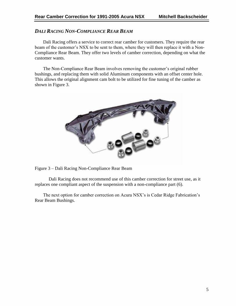
Dali Racing offers a service to correct rear camber for customers. They require the rear
beam of the customer’s NSX to be sent to them, where they will then replace it with a Non-
Compliance Rear Beam. They offer two levels of camber correction, depending on what the
customer wants.
The Non-Compliance Rear Beam involves removing the customer’s original rubber
bushings, and replacing them with solid Aluminum components with an offset center hole.
This allows the original alignment cam bolt to be utilized for fine tuning of the camber as
shown in Figure 3.
Figure 3 – Dali Racing Non-Compliance Rear Beam
Dali Racing does not recommend use of this camber correction for street use, as it
replaces one compliant aspect of the suspension with a non-compliance part (6).
The next option for camber correction on Acura NSX’s is Cedar Ridge Fabrication’s
Rear Beam Bushings.
Rear Camber Correction for 1991-2005 Acura NSX Mitchell Backscheider
6
CEDAR RIDGE FABRICATION REAR BEAM BUSHINGS
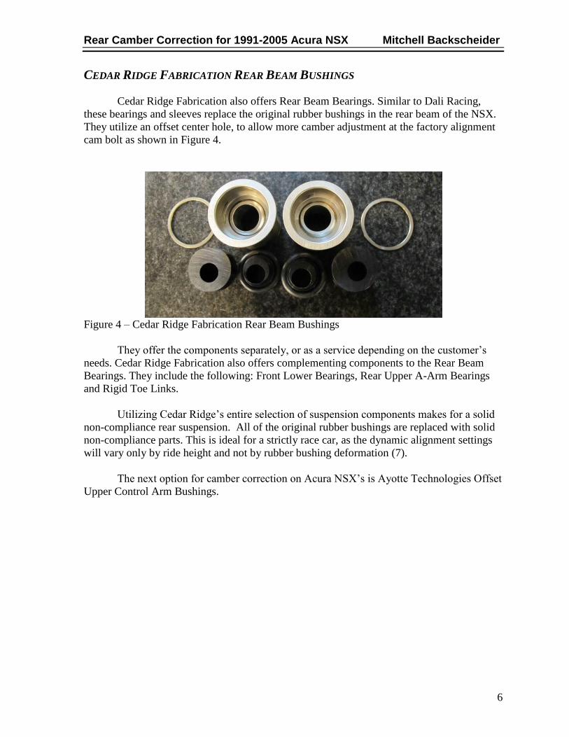
Cedar Ridge Fabrication also offers Rear Beam Bearings. Similar to Dali Racing,
these bearings and sleeves replace the original rubber bushings in the rear beam of the NSX.
They utilize an offset center hole, to allow more camber adjustment at the factory alignment
cam bolt as shown in Figure 4.
Figure 4 – Cedar Ridge Fabrication Rear Beam Bushings
They offer the components separately, or as a service depending on the customer’s
needs. Cedar Ridge Fabrication also offers complementing components to the Rear Beam
Bearings. They include the following: Front Lower Bearings, Rear Upper A-Arm Bearings
and Rigid Toe Links.
Utilizing Cedar Ridge’s entire selection of suspension components makes for a solid
non-compliance rear suspension. All of the original rubber bushings are replaced with solid
non-compliance parts. This is ideal for a strictly race car, as the dynamic alignment settings
will vary only by ride height and not by rubber bushing deformation (7).
The next option for camber correction on Acura NSX’s is Ayotte Technologies Offset
Upper Control Arm Bushings.

Rear Camber Correction for 1991-2005 Acura NSX Mitchell Backscheider
7
AYOTTE TECHNOLOGIES OFFSET UPPER CONTROL ARM BUSHINGS
Ayotte Technologies takes a slightly different approach than the aforementioned
companies. They correct camber by replacing the rear upper control arm’s axial compliant
bushings with non-compliant self lubricating polymer bearing material mated to a billet T6-
6061 offset pivot. Offsetting the axial pivot of the upper control arm away from the chassis
allows a gain of about +2.0±0.2° of positive camber as displayed in Figure 5 (8).
Figure 5 – Ayotte Technologies Offset Bushings
Ayotte Technologies offers this product as both a part and a service. The customer can
send their upper control arms to them, where they will then replace the existing rubber
bushings with the new non-compliant offset bearings. They also offer just the parts, but it is
noted that this is not intended to be a do it yourself kit, a shop that can press out the original
pivots would be required; installation of the new parts requires specially designed tools.
Ayotte Technologies stopped manufacturing this camber correction kit in 2009. Due to
the poor economy and low sales, Thom could just not feasibly justify making only a couple
parts and selling them in such low volumes.
Hardrace is an aftermarket company that specializes in manufacturing replacement
parts that allow for increased adjustment.

Rear Camber Correction for 1991-2005 Acura NSX Mitchell Backscheider
8
HARDRACE PILLOWBALL REAR UPPER ADJUSTABLE CONTROL ARMS
Hardrace was founded in 1998. Hardrace specializes in manufacturing reinforced
suspension products for street and race applications. From hardened rubber bushings, to
pillow ball bushings, Hardrace offer a variety of suspension components (9).
The product displayed in Figure 6 is a replacement camber correction arm for a 2000-
2009 Honda S2000. This part replaces the factory upper control arm with the new Hardrace
part. Included with this part is a machined control arm, with new bushings and ball joints.
The machined fit slider allows for the ball joint to be positioned at a desired location
for ideal camber adjustment. This sliding ball joint is one very common method of adjusting
the camber angles, and can be found of a variety of makes and brands camber kits.
Figure 6 – Hardrace Honda S2000 Rear Camber Kit
Hardrace’s replacement control arms offer a product that is relatively easier for the
customer to install, as no specialty tools are needed for installation.
Hardrace offers adjustable control arms for a variety of makes and models.

Rear Camber Correction for 1991-2005 Acura NSX Mitchell Backscheider
9
HARDRACE REAR ADJUSTABLE LOWER CONTROL ARM
Hardrace was founded in 1998. Hardrace specializes in manufacturing reinforced
suspension products for street and race applications. From hardened rubber bushings, to
pillow ball bushings, Hardrace offer a variety of suspension components (10).
The product displayed in Figure 7 is a replacement lower control arm for a 1989-1994
Nissan S13 and R32 Skyline. This part replaces the factory lower control arm with the new
Hardrace part. Included with this part is a fabricated control arm, with new bushings and
spherical ball joints.
The spherical ball joint allows for adjustment of spindle angles for the desired alignment
values. Although the adjustment is more difficult than a sliding style ball joint, the spherical
ball joint offers a more cost effective method to adjustable alignment.
Figure 7 – Hardrace Nissan 240sx Lower Control Arm
Hardrace’s replacement control arms offer a product that is relatively easier for the
customer to install, as no specialty tools are needed for installation.
Based on the research, ten features from the various types of camber correction stuck
out the most. The next step was to determine the features in order of importance. They were
then labeled as Customer Features and put into a survey to decide the order of importance.
Rear Camber Correction for 1991-2005 Acura NSX Mitchell Backscheider
10
CUSTOMER FEEDBACK, FEATURES AND OBJECTIVES
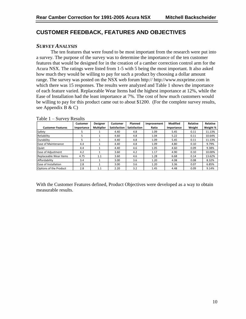
SURVEY ANALYSIS The ten features that were found to be most important from the research were put into
a survey. The purpose of the survey was to determine the importance of the ten customer
features that would be designed for in the creation of a camber correction control arm for the
Acura NSX. The ratings were listed from 1-5 with 5 being the most important. It also asked
how much they would be willing to pay for such a product by choosing a dollar amount
range. The survey was posted on the NSX web forum http:// http://www.nsxprime.com in
which there was 15 responses. The results were analyzed and Table 1 shows the importance
of each feature varied. Replaceable Wear Items had the highest importance at 12%, while the
Ease of Installation had the least importance at 7%. The cost of how much customers would
be willing to pay for this product came out to about $1200. (For the complete survey results,
see Appendix B & C)
Table 1 – Survey Results
With the Customer Features defined, Product Objectives were developed as a way to obtain
measurable results.
Customer Features
Customer
Importance
Designer
Multiplier
Customer
Satisfaction
Planned
Satisfaction
Improvement
Ratio
Modified
Importance
Relative
Weight
Relative
Weight %
Safety 5 1 4.40 4.8 1.09 5.45 0.11 11.13%
Reliability 5 1 4.60 4.8 1.04 5.22 0.11 10.64%
Durability 5 1 4.40 4.8 1.09 5.45 0.11 11.13%
Ease of Maintenance 4.4 1 4.40 4.8 1.09 4.80 0.10 9.79%
Quiet 4.4 1 4.40 4.6 1.05 4.60 0.09 9.38%
Ease of Adjustment 4.2 1 3.60 4.2 1.17 4.90 0.10 10.00%
Replaceable Wear Items 4.75 1.1 3.60 4.6 1.28 6.68 0.14 13.62%
Affordability 3.4 1 3.00 3.6 1.20 4.08 0.08 8.32%
Ease of Installation 2.8 1 3.00 3.6 1.20 3.36 0.07 6.85%
Options of the Product 2.8 1.1 2.20 3.2 1.45 4.48 0.09 9.14%

Rear Camber Correction for 1991-2005 Acura NSX Mitchell Backscheider
11
PRODUCT FEATURES AND OBJECTIVES The Product Features are the same as the customer features rated on the survey. They
are listed in order of most to least important in accordance with the survey. Under each
feature are Product Objectives. Product Objectives are goals in which to meet the customer
features. The customer features obtained were translated into measurable variables to
determine if the Project Objectives were met. (See Appendix D for complete Product
Objectives.)
1. Replaceable Wear Items (14%)
a. Replacement bushings and ball joints will be offered as wear components
2. Safety (11%)
a. An appropriate factor of safety in the design.
b. The safety factor will exceed any shock stresses the control arm may
encounter.
3. Reliability (11%)
a. The mechanical assembly will follow a list of allowable torques for all
fasteners included with the finished product.
b. Industry Hardware standards (of similar applications) will be used to
determine hardware selection.
4. Durability (11%)
a. The material selection of the new control arm will be rust resistant.
b. The control arm will also be powder coated to resist corrosion.
c. The included bushings and ball joints will meet or exceed the specifications of
the original equipment on the vehicle.
5. Ease of Maintenance (10%)
a. Visibility of all inspection items will be in plain sight when on an automotive
service lift. (removal of no parts for inspection will be required)
b. Maintenance will include routine inspection of bushings and ball joints for
damage or wear. (same as factory repair manual)
6. Ease of Adjustment (10%)
a. Each control arm will be able to be adjusted in under ten minutes when on an
alignment lift.
b. Adjustment Hardware will be accessible without the removal of any additional
parts.
i. Standard tools will be used to make adjustments.
7. Quiet (9%)
a. Measurement (with decibel meter) will be performed both before and after
installation of the new control arm under the same test conditions.
i. The street kit will not add any additional noise to the vehicle when

Rear Camber Correction for 1991-2005 Acura NSX Mitchell Backscheider
12
compared to the original control arm.
ii. The race kit may add additional noise to the ride of the vehicle when
compared to the original control arm.
8. Options of product (10%)
a. The product will be offered in two different kits.
i. Street (compliance) kit utilizing bushings that allow normal flexibility.
(Rubber, Polyurethane, etc)
ii. Race (non-compliance) kit utilizing bushings that do not allow
flexibility (delrin).
1.Material properties will determine bushing selection.
9. Affordability (8%)
a. The complete set of (2) upper control arms with all included brackets,
bushings, ball joints and hardware will not exceed $1200 to purchase.
10. Ease of Installation (7%)
a. The total installation time for a qualified mechanic with the standard tools
should be no more than four hours.
After coming up with the Product Objectives, the next step was to analyze the importance of
each.

Rear Camber Correction for 1991-2005 Acura NSX Mitchell Backscheider
13
ENGINEERING CHARACTERISTICS The product objectives were then put into a Quality Function Deployment labeled as
Engineering Characteristics and were cross referenced with all the Product Features and
weights to determine how important each was to the entire design. They are listed in Table 2
by percentage in the order of higher importance to lower with OEM specified bushings and
ball joints having the most importance and Standard Tools having the least importance.
Table 2 – Engineering Characteristics
Engineering Characteristic Importance %
OEM Spec. Bushings/Ball Joints 14%
Material 12%
Replaceable Standard Parts 11%
Hardware Torques 10%
Standard Hardware 8%
Product Variations Offered 8%
Installation Time 7%
Adjustment Time 7%
Design Safety Factor 6%
Maintenance - Service Manual 6%
Interior Decibel Test 5%
Standard Tools Used 5%
After the importance of each Product Objective and Engineering Characteristic were
realized, Concepts could then be developed.
Rear Camber Correction for 1991-2005 Acura NSX Mitchell Backscheider
14
CONCEPT GENERATION AND SELECTION
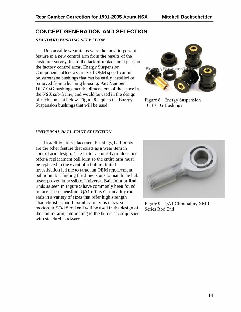
STANDARD BUSHING SELECTION
Replaceable wear items were the most important
feature in a new control arm from the results of the
customer survey due to the lack of replacement parts in
the factory control arms. Energy Suspension
Components offers a variety of OEM specification
polyurethane bushings that can be easily installed or
removed from a bushing housing. Part Number
16.3104G bushings met the dimensions of the space in
the NSX sub-frame, and would be used in the design
of each concept below. Figure 8 depicts the Energy
Suspension bushings that will be used.
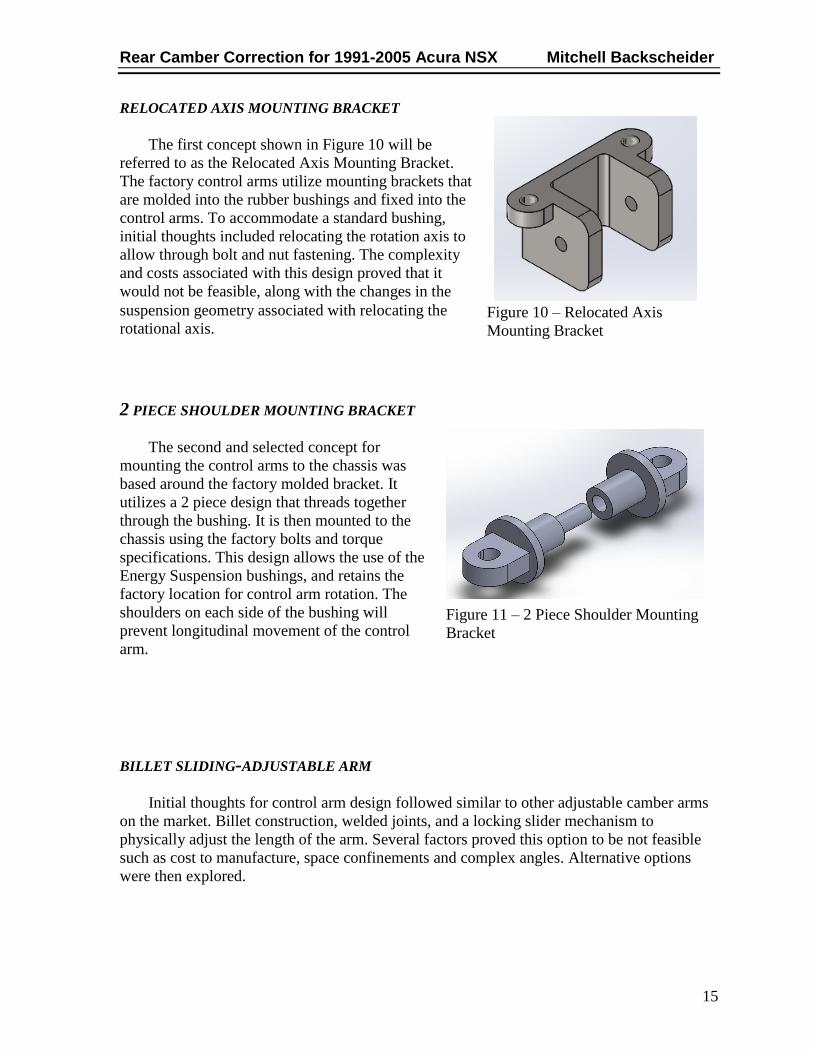
UNIVERSAL BALL JOINT SELECTION
In addition to replacement bushings, ball joints
are the other feature that exists as a wear item in
control arm design. The factory control arm does not
offer a replacement ball joint so the entire arm must
be replaced in the event of a failure. Initial
investigation led me to target an OEM replacement
ball joint, but finding the dimensions to match the hub
insert proved impossible. Universal Ball Joint or Rod
Ends as seen in Figure 9 have commonly been found
in race car suspension. QA1 offers Chromalloy rod
ends in a variety of sizes that offer high strength
characteristics and flexibility in terms of swivel
motion. A 5/8-18 rod end will be used in the design of
the control arm, and mating to the hub is accomplished
with standard hardware.
Figure 8 - Energy Suspension
16.3104G Bushings
Figure 9 - QA1 Chromalloy XMR
Series Rod End
Rear Camber Correction for 1991-2005 Acura NSX Mitchell Backscheider
15
RELOCATED AXIS MOUNTING BRACKET
The first concept shown in Figure 10 will be
referred to as the Relocated Axis Mounting Bracket.
The factory control arms utilize mounting brackets that
are molded into the rubber bushings and fixed into the
control arms. To accommodate a standard bushing,
initial thoughts included relocating the rotation axis to
allow through bolt and nut fastening. The complexity
and costs associated with this design proved that it
would not be feasible, along with the changes in the
suspension geometry associated with relocating the
rotational axis.
2 PIECE SHOULDER MOUNTING BRACKET
The second and selected concept for
mounting the control arms to the chassis was
based around the factory molded bracket. It
utilizes a 2 piece design that threads together
through the bushing. It is then mounted to the
chassis using the factory bolts and torque
specifications. This design allows the use of the
Energy Suspension bushings, and retains the
factory location for control arm rotation. The
shoulders on each side of the bushing will
prevent longitudinal movement of the control
arm.
BILLET SLIDING-ADJUSTABLE ARM
Initial thoughts for control arm design followed similar to other adjustable camber arms
on the market. Billet construction, welded joints, and a locking slider mechanism to
physically adjust the length of the arm. Several factors proved this option to be not feasible
such as cost to manufacture, space confinements and complex angles. Alternative options
were then explored.
Figure 10 – Relocated Axis
Mounting Bracket
Figure 11 – 2 Piece Shoulder Mounting
Bracket

Rear Camber Correction for 1991-2005 Acura NSX Mitchell Backscheider
16
TUBULAR FIXED LENGTH ARM
Tubular Steel was selected to be the material of choice as it is relatively cheap, easy to
weld, and very strong. This approach utilizes a fixed camber correction in the overall length
of the arm. The camber adjustment will still be retained in the factory lower control arm
mounting point for fine tuning alignment values through the use of the cam bolt. The key
mounting points were first modeled and then connected with a structure of supports. The bent
section utilizes a standard three inch center line radius bend that met the available resources
for tube construction. The selected tubing is 4130 Chromalloy Steel with a 1” outer diameter
and a 0.120” wall thickness. The design in Figure 12 below is the selected design, as from a
cost and feasibility standpoint it met all the requirements set forth.
Figure 12 – Fixed Length Camber Correction Arm
Figure 13 – Selected Components in Assembly

Rear Camber Correction for 1991-2005 Acura NSX Mitchell Backscheider
17
CALCULATIONS
CALCULATING THE FORCES IN THE CONTROL ARM
Force calculation began by estimating the heaviest corner weight of an Acura NSX.
This was achieved by finding the heaviest model; an automatic transmission, targa top NSX
which has a curb weight of 3,204 lbs. This was then rounded to 3,500 lbs for a design weight.
The weight distribution front to rear for the NSX is approximately 42/58.
𝑅𝑒𝑎𝑟 𝐶𝑜𝑟𝑛𝑒𝑟 𝑊𝑒𝑖𝑔𝑡 = 𝑅𝑒𝑎𝑟 𝑊𝑒𝑖𝑔𝑡 𝐷𝑖𝑠𝑡𝑟𝑖𝑏𝑢𝑡𝑖𝑜𝑛 ∗ 𝐷𝑒𝑠𝑖𝑔𝑛 𝑊𝑒𝑖𝑔𝑡
2
𝑅𝑒𝑎𝑟 𝐶𝑜𝑟𝑛𝑒𝑟 𝑊𝑒𝑖𝑔𝑡 = 0.58 ∗ 3500𝑙𝑏𝑠
2= 1,015 𝑙𝑏𝑠
Controls arms see the most loads during cornering. In an extreme cornering situation
with high traction tires and high speeds, I anticipate the max acceleration in a corner to be
2g-forces. The 3,500lb design weight is equal to 1,587.57kg. The equations below break
down the acceleration force for the whole vehicle, and then for the rear corner.
𝐹 = 𝑣𝑒𝑖𝑐𝑙𝑒 𝑚𝑎𝑠𝑠 ∗ 2 𝑔
𝐹 = 1587.57𝑘𝑔 ∗ 2 9.8𝑚
𝑠2 = 31,116.37 𝑁
𝑅𝑒𝑎𝑟 𝐶𝑜𝑟𝑛𝑒𝑟 𝐹𝑜𝑟𝑐𝑒 = 𝑅𝑒𝑎𝑟 𝑊𝑒𝑖𝑔𝑡 𝐷𝑖𝑠𝑡𝑟𝑖𝑏𝑢𝑡𝑖𝑜𝑛 ∗ 𝐿𝑎𝑡𝑒𝑟𝑎𝑙 𝐹𝑜𝑟𝑐𝑒
2
𝑅𝑒𝑎𝑟 𝐶𝑜𝑟𝑛𝑒𝑟 𝐹𝑜𝑟𝑐𝑒 = 0.58 ∗ 31,116.37 𝑁
2= 9,023.75 𝑁 𝑜𝑟 2,028.62 𝑙𝑏𝑓

Rear Camber Correction for 1991-2005 Acura NSX Mitchell Backscheider
18
FREE BODY DIAGRAM
Dimensions were then pulled from the vehicle to model a free body diagram of the rear
suspension components as seen in the Figure below. In this particular situation, the upper
control arm will experience a compressive load of 2,225.6 lbf, which will be used in the
testing of this control arm. The control arms were pinned at the body mounting points and
break down as follows.
BD: Upper Control Arm
AC: Lower Control Arm
BA: Knuckle
FE: Hub/Spindle
FG: Wheel/Tire
F2: Shock Absorber
F1: Corner Weight
F3: Cornering Force
Figure 14 – Free Body Diagram 1
Table 3 – Compressive Force Components
Equations Results
∑M = 0 => 0.732 × RD17[Y] + 0.164 × RD17[X] = 0
∑F[X] = 0 => RB17[X] + RD17[X] = 0
∑F[Y] = 0 => RB17[Y] + RD17[Y] = 0
∑F[X] = 0 => RD[X] − RD17[X] = 0
∑F[Y] = 0 => RD[Y] − RD17[Y] = 0
RB17[X] = 2171.467 lb
RB17[Y] = −488.002 lb
RD17[X] = −2171.467 lb
RD17[Y] = 488.002 lb
Rear Camber Correction for 1991-2005 Acura NSX Mitchell Backscheider
19
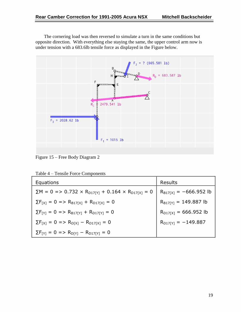
The cornering load was then reversed to simulate a turn in the same conditions but
opposite direction. With everything else staying the same, the upper control arm now is
under tension with a 683.6lb tensile force as displayed in the Figure below.
Figure 15 – Free Body Diagram 2
Table 4 – Tensile Force Components
Equations Results
∑M = 0 => 0.732 × RD17[Y] + 0.164 × RD17[X] = 0
∑F[X] = 0 => RB17[X] + RD17[X] = 0
∑F[Y] = 0 => RB17[Y] + RD17[Y] = 0
∑F[X] = 0 => RD[X] − RD17[X] = 0
∑F[Y] = 0 => RD[Y] − RD17[Y] = 0
RB17[X] = −666.952 lb
RB17[Y] = 149.887 lb
RD17[X] = 666.952 lb
RD17[Y] = −149.887
Rear Camber Correction for 1991-2005 Acura NSX Mitchell Backscheider
20
FABRICATION AND ASSEMBLY
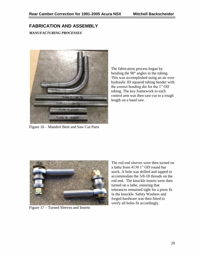
MANUFACTURING PROCESSES
The fabrication process began by
bending the 90° angles in the tubing.
This was accomplished using an air over
hydraulic JD squared tubing bender with
the correct bending die for the 1” OD
tubing. The key framework to each
control arm was then saw-cut to a rough
length on a band saw.
Figure 16 – Mandrel Bent and Saw Cut Parts
The rod end sleeves were then turned on
a lathe from 4130 1” OD round bar
stock. A hole was drilled and tapped to
accommodate the 5/8-18 threads on the
rod end. The knuckle inserts were then
turned on a lathe, ensuring that
tolerances remained tight for a press fit
in the knuckle. Safety Washers and
forged hardware was then fitted to
verify all holes fit accordingly.
Figure 17 – Turned Sleeves and Inserts
Rear Camber Correction for 1991-2005 Acura NSX Mitchell Backscheider
21
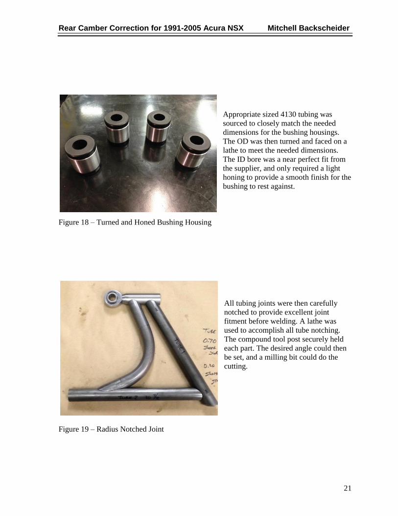
Appropriate sized 4130 tubing was
sourced to closely match the needed
dimensions for the bushing housings.
The OD was then turned and faced on a
lathe to meet the needed dimensions.
The ID bore was a near perfect fit from
the supplier, and only required a light
honing to provide a smooth finish for the
bushing to rest against.
Figure 18 – Turned and Honed Bushing Housing
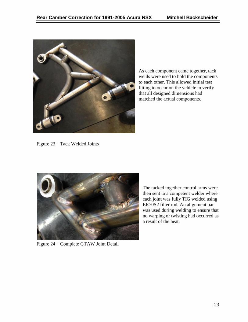
All tubing joints were then carefully
notched to provide excellent joint
fitment before welding. A lathe was
used to accomplish all tube notching.
The compound tool post securely held
each part. The desired angle could then
be set, and a milling bit could do the
cutting.
Figure 19 – Radius Notched Joint

Rear Camber Correction for 1991-2005 Acura NSX Mitchell Backscheider
22
Each part was carefully shaped in the
methods mentioned above, and slowly
came together to create the outline of
the control arm. An alignment bar was
fabricated to ensure that each of the
bushing sleeves remained in alignment
during fit up and tack welding.
Figure 20 – Alignment Bar
Next the mounting brackets were turned
on a lathe to meet the dimensions
needed for the pre milling preparation.
They were then drilled and tapped to
accept the ½-20 threaded rod for
assembly through the bushings.
Figure 21 – Turned Mounting Brackets
The mounting brackets were then sent to a
machine shop for the final stage of
machining. They were CNC milled to have
the radius along with the elongated holes
cut in. These parts would then accept the
mounting hardware to secure the arms to
the chassis.
Figure 22 – CNC Milled Mounting Brackets
Rear Camber Correction for 1991-2005 Acura NSX Mitchell Backscheider
23
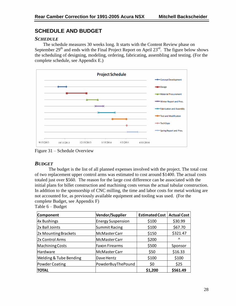
As each component came together, tack
welds were used to hold the components
to each other. This allowed initial test
fitting to occur on the vehicle to verify
that all designed dimensions had
matched the actual components.
Figure 23 – Tack Welded Joints
The tacked together control arms were
then sent to a competent welder where
each joint was fully TIG welded using
ER70S2 filler rod. An alignment bar
was used during welding to ensure that
no warping or twisting had occurred as
a result of the heat.
Figure 24 – Complete GTAW Joint Detail

Rear Camber Correction for 1991-2005 Acura NSX Mitchell Backscheider
24
The completely welded control arms
were once again assembled and tested
for fit up. It was at this point that the
control arm was ready for load testing,
which can be viewed in the next
section of this report.
Figure 25 – Complete GTAW Welded Control Arm
CORROSION RESISTANCE
After testing was complete on each
control arm, they were media blasted
to remove any contaminants on the
surface. They were further cleaned
and then powder coated. After
curing at 400° F for approximately
12 minutes, the parts were allowed to
cool where the finish would finally
cure.
Figure 26 – Powder Coated Finish

Rear Camber Correction for 1991-2005 Acura NSX Mitchell Backscheider
25
FINAL ASSEMBLY
After completion of all machining, testing, and corrosion processes, the control arms
were ready for final assembly and installation. Assembly consisted of simply threading in the
rod end, pressing in the bushings, and threading together the mounting brackets through the
bushings. The control arm is then fastened to the chassis utilizing the 4 factory bolts and
torqued to the values listed in the factory service manual. The taper insert could then be
started into the knuckle, and the bolt dropped through each component in the rod end. As this
bolt was tightened, the knuckle insert was pressed into the knuckle until seated and torqued
accordingly.
Figure 27 – Installed Component

Rear Camber Correction for 1991-2005 Acura NSX Mitchell Backscheider
26
TESTING
TESTING PROCESS
To test the integrity of the fabricated control arms,
along with a comparison to the model developed in
Solidworks, a hydraulic press was used to apply
load to the control arms. A jig was fabricated to fix
the bushing housings of the control arms to the base
of the press. The ram was then fixed to the control
arm through the rod end. The load was applied as a
compressive load, and to be tested to the values
calculated from the free body diagram.
Figure 28 – Testing Jig
A dial indicator was placed under the rod end and
used to measure the deflection of the control arm at
each increment of load. The control arms were
loaded to 2,270 lbs of compressive force, and the
results can be analyzed on the next page.
Figure 29 – Deflection Measurement

Rear Camber Correction for 1991-2005 Acura NSX Mitchell Backscheider
27
TESTING RESULTS
The data recorded in Table 5 is the raw data pulled from the physical testing of the
control arms. The Estimated Displacement values come from a Solidworks Simulation model
of the control arm with the same force applied.
Table 5 – Testing Data
The graphical results are depicted in the Figure below. The Red and Black lines on the
graph depict the actual deflection values recorded during the physical testing. The nearly
hidden blue line is the estimated deflection from the Solidworks Simulation. The purple
horizontal line represents the maximum safe deflection before the material will begin to
exceed its yield strength. With a safety factor of 2.0 the 5/8-18 fastener securing the rod end
to the control arm will exceed its yield strength at loads in excess of 6900lbs. The Maximum
Safe Deflection is derived from the Solidworks Simulation based on the deflection value
estimated at a 6900lb load. At the expected and tested loads, our deflection remained well
beneath the maximum safe deflection, which confirms the integrity and safety of these
control arms.
Figure 30 – Testing Results
0.0000
0.0100
0.0200
0.0300
0.0400
0.0500
0.0600
0 500 1000 1500 2000 2500
Dis
pla
cem
ent
(in
)
Load (lbs)
Force vs. Displacement
Estimated Displacement
(in)Control Arm 1
Control Arm 2
Rear Camber Correction for 1991-2005 Acura NSX Mitchell Backscheider
28
SCHEDULE AND BUDGET
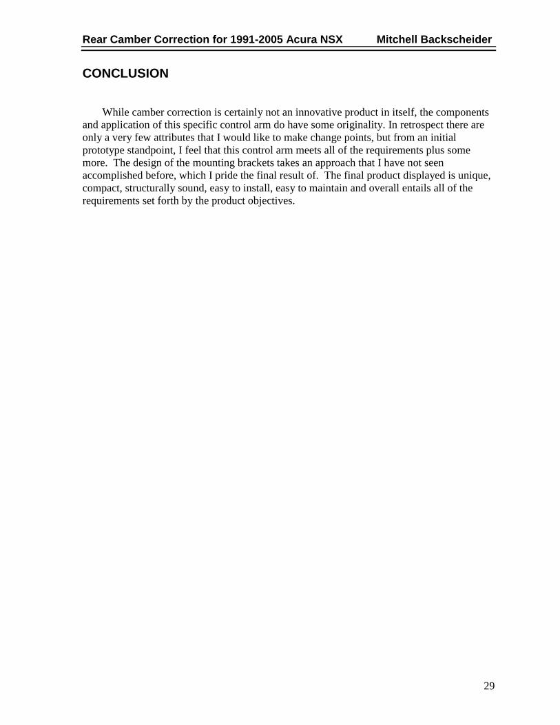
SCHEDULE The schedule measures 30 weeks long. It starts with the Content Review phase on
September 29th
and ends with the Final Project Report on April 23rd
. The figure below shows
the scheduling of designing, modeling, ordering, fabricating, assembling and testing. (For the
complete schedule, see Appendix E.)
Figure 31 – Schedule Overview
BUDGET The budget is the list of all planned expenses involved with the project. The total cost
of two replacement upper control arms was estimated to cost around $1400. The actual costs
totaled just over $560. The reason for the large cost difference can be associated with the
initial plans for billet construction and machining costs versus the actual tubular construction.
In addition to the sponsorship of CNC milling, the time and labor costs for metal working are
not accounted for, as previously available equipment and tooling was used. (For the
complete Budget, see Appendix F)
Table 6 – Budget
Component Vendor/Supplier Estimated Cost Actual Cost
4x Bushings Energy Suspension $100 $30.99
2x Ball Joints Summit Racing $100 $67.70
2x Mounting Brackets McMaster Carr $150 $321.47
2x Control Arms McMaster Carr $200 ^
Machining Costs Faxon Firearms $500 Sponsor
Hardware McMaster Carr $50 $16.33
Welding & Tube Bending Dave Hentz $100 $100
Powder Coating PowderBuyThePound $0 $25
TOTAL $1,200 $561.49
Rear Camber Correction for 1991-2005 Acura NSX Mitchell Backscheider
29
CONCLUSION
While camber correction is certainly not an innovative product in itself, the components
and application of this specific control arm do have some originality. In retrospect there are
only a very few attributes that I would like to make change points, but from an initial
prototype standpoint, I feel that this control arm meets all of the requirements plus some
more. The design of the mounting brackets takes an approach that I have not seen
accomplished before, which I pride the final result of. The final product displayed is unique,
compact, structurally sound, easy to install, easy to maintain and overall entails all of the
requirements set forth by the product objectives.

Rear Camber Correction for 1991-2005 Acura NSX Mitchell Backscheider
30
WORKS CITED
1. Wikipedia. [Online] Otober 9, 2013. http://en.wikipedia.org/wiki/Honda_NSX.
2. Urlage, Brian. Cincinnati, September 2, 2013.
3. Nguyen, Andrew. Cincinnati, September 2, 2013.
4. Car Bibles. [Online] [Cited: October 5, 2013.]
http://www.carbibles.com/suspension_bible.html.
5. Discount Tire. [Online] October 5, 2013.
http://www.discounttire.com/dtcs/infoAlignment.dos.
6. Dali Racing. [Online] [Cited: August 27, 2013.] http://daliracing.com/v666-
5/catalog/index_browse_part.cfm?focus=2247.
7. Cedar Ridge Fabrication. [Online] [Cited: August 29, 2013.]
http://www.cedarridgefabrication.com/NSX_Suspension.
8. NSX Prime. [Online] [Cited: September 2, 2013.]
http://www.nsxprime.com/forum/showthread.php/84729-Camber-Correction-
Hardware?highlight=camber+correction+hardware.
9. Hardrace. [Online] [Cited: September 2, 2013.]
http://www.hardrace.com/products.asp?strClass1=11&strClass2=31.
10. Hardrace. [Online] [Cited: September 2, 2013.]
http://www.hardrace.com/products.asp?strClass1=7.

31
APPENDIX A – RESEARCH
Interview with Performance NSX Shop Owner Brian Urlage: 1675 Ohio 28
Goshen, Ohio 45122
Brian Urlage has 21 years of experience in the car industry.
He opened Source1 Automotive in 2006, where they are now known
nation-wide as a leader in Performance NSX modification and
maintenance.
Brian notes that the aftermarket support for the NSX is substantially
less than many other often modified automobiles.
Brian sees camber issues often, as there is no cost effective way to
manage this issue on customer’s vehicles. Brian notes that being able to
manage camber issues for customer will improve tire wear for
customers that simply want to drive their cars, along with improving
traction in straight line racing and light turns.
He sees there being a high demand for this product if quality and ease
of adjustment is there. He stated that NSX owners do not mind paying
for a quality product that allows for ease of installation and improves
troublesome issues such as camber.
Brian has faith in my skills as he has seen the quality of work I have
produced on other projects and is excited to see where I can take this
project.
Interview with Acura NSX Builder Andrew Nguyen: 5656 Cheviot Road
Cincinnati, Ohio 45247
Andrew Nguyen has been building cars for 14 years.
Andrew enjoys the exterior of the NSX the most, as he feels it was so
ahead of its time appearance-wise.
Andrew feels there is a solid aftermarket support, as modifying these
vehicles has become more common as companies have taken up many
challenges to meet customer’s needs.
He would like to see camber adjustment that allows for running wider
wheel/tire combinations with the best contact patch. Also for quick
adjustment depending on the type of driving or racing he is taking part
in.
He prefers sliding style ball joint’s as they offer quick and easy
adjustment of camber.
Cost of parts is not an issue to Andrew, as he is most concerned about
durability and ease of adjustment.
Andrew is excited to see the finished product; along with all the stages
leading up to it, he plans to be my first customer.

32
Dali Racing Non-Compliance Rear Beam
Dali Racing offers a service to correct rear camber for customers.
They require the rear beam of the customer’s NSX to be sent to
them, where they will then replace it with a Non-Compliance
Rear Beam. They offer two levels of camber correction,
depending on what the customer wants.
The Non-Compliance Rear Beam involves removing the
customer’s original rubber bushings, and replacing them with
solid Aluminum components with an offset center hole. This
allows the original alignment cam bolt to be utilized for fine
tuning of the camber.
Dali Racing does not recommend use of this camber correction
for street use, as it replaces one compliant aspect of the
suspension with a non-compliance part.
This Product:
Eliminates the possibility of Dynamic camber settings
Should be used with Non-Compliance Toe Links for best
handling improvement
Is Sold Exchange Only in Our Shop – Requires
Modification of the Rear Beam
$700.00 USD
Offered only as a
service, so there is a gap
of downtime for the
customer.
Still requires customer
to remove and ship out
their rear beam. Along
with installation upon
receiving the modified
beam.
Not recommended for
street use.
Requires permanent
modification to the rear
beam.
Less than ideal customer
service.
http://daliracing.com/v666-
5/catalog/index_browse_part.cfm?focus=2247
8/27/2013

33
Cedar Ridge Fabrication (TitaniumDave) Rear Beam Bearings
Cedar Ridge Fabrication also offers Rear Beam Bearings. Similar to
Dali Racing, these bearings and sleeves replace the original rubber
bushings in the rear beam of the NSX. They utilize an offset center
hole, to allow more camber adjustment at the factory alignment cam
bolt.
They offer the components separately, or as a service depending on
the customer’s needs. Cedar Ridge Fabrication also offers
complementing components to the Rear Beam Bearings. They
include the following: Front Lower Bearings, Rear Upper A-Arm
Bearings and Rigid Toe Links.
Utilizing Cedar Ridge’s entire selection of suspension components
makes for a solid non-compliance rear suspension. All of the
original rubber bushings are replaced with solid non-compliance
parts. This is ideal for a strictly race car, as the dynamic alignment
settings will vary only by ride height and not by rubber bushing
deformation.
$480.00 USD (two
locations)
Installation required
for these rear beam
bearings is extremely
involved, and cannot
be done by an average
car enthusiast.
Complete non-
compliance camber
correction (four
locations) costs
$880.00 and still need
to be installed by the
customer.
Complete non-
compliance kit (twelve
locations) costs
$3600.00 USD
installed into the
customer’s NSX.
Requires permanent
modification to the
rear beam.
High quality product,
high cost, not
recommended for most
street driven cars.
http://www.cedarridgefabrication.com/NSX_Suspension
8/29/2013

34
Ayotte Technologies (Thom) Offset Upper Control Arm
Bushings
Ayotte Technologies takes a slightly different approach than the
aforementioned companies. They correct camber by replacing the
rear upper control arm’s axial compliant bushings with non-
compliant self lubricating polymer bearing material mated to a
billet T6-6061 offset pivot. Offsetting the axial pivot of the upper
control arm away from the chassis allows a gain of about
+2.0±0.2° of positive camber.
Ayotte Technologies offers this product as both a part and a
service. The customer can send their upper control arms to them,
where they will then replace the existing rubber bushings with the
new non-compliant offset bearings. They also offer just the parts,
but it is noted that this is not intended to be a do it yourself kit, a
shop that can press out the original pivots would be required;
installation of the new parts requires specially designed tools.
Ayotte Technologies stopped manufacturing this camber
correction kit in 2009. Due to the poor economy and low sales,
Thom could just not feasibly justify making only a couple parts
and selling them in such low volumes.
$450.00 USD
Installation required
offset control arm
bearings is extremely
involved, and cannot be
done by an average car
enthusiast.
Reuses the non-
replaceable original ball
joints.
Known to squeak and
make noise and need
often lubrication.
Requires permanent
modification to the
upper control arms.
They are no longer
manufactured.
http://www.nsxprime.com/forum/showthread.php/84729-
Camber-Correction-
Hardware?highlight=camber+correction+hardware
9/2/13

35
Hardrace Pillowball Rear Upper Adjustable Control Arms
(00-09 Honda S2000)
Hardrace was founded in 1998. Hardrace specializes in
manufacturing reinforced suspension products for street and race
applications. From hardened rubber bushings, to pillow ball
bushings, Hardrace offer a variety of suspension components.
The product displayed above is a replacement camber correction
arm for a 2000-2009 Honda S2000. This part replaces the factory
upper control arm with the new Hardrace part. Included with this
part is a machined control arm, with new bushings and ball joints.
The machined fit slider allows for the ball joint to be positioned at
a desired location for ideal camber adjustment. This sliding ball
joint is one very common method of adjusting the camber angles,
and can be found of a variety of makes and brands camber kits.
Hardrace’s replacement control arms offer a product that is
relatively easier for the customer to install, as no specialty tools
are needed for installation.
$535.00 USD
Offers a cost effective
method to replace and
adjust camber.
Includes new bushings
and ball joints.
Relatively easy
installation.
Priced well for a quality
product.
Not offered for the
Acura NSX.
http://www.hardrace.com/products.asp?strClass1=11&strCla
ss2=31
9/2/13

36
Hardrace Rear Adjustable Lower Control Arm (Nissan S13
and R32 Skyline)
Hardrace was founded in 1998. Hardrace specializes in
manufacturing reinforced suspension products for street and race
applications. From hardened rubber bushings, to pillow ball
bushings, Hardrace offer a variety of suspension components.
The product displayed above is a replacement lower control arm
for a 1989-1994 Nissan S13 and R32 Skyline. This part replaces
the factory lower control arm with the new Hardrace part.
Included with this part is a fabricated control arm, with new
bushings and spherical ball joints.
The spherical ball joint allows for adjustment of spindle angles
for the desired alignment values. Although the adjustment is more
difficult than a sliding style ball joint, the spherical ball joint
offers a more cost effective method to adjustable alignment.
Hardrace’s replacement control arms offer a product that is
relatively easier for the customer to install, as no specialty tools
are needed for installation.
$449.00 USD
Offers a cost effective
method to replace and
adjust alignment angles.
Includes new bushings
and spherical ball joints.
Relatively easy
installation.
Priced well for a quality
product.
Not offered for the
Acura NSX.
http://www.hardrace.com/products.asp?strClass1=7
9/2/13

37
APPENDIX B – CUSTOMER SURVEY
The purpose of this survey is to evaluate what features are most important in the design of a new
rear camber kit for Acura NSX’s. This information will also be used to evaluate how satisfied
customers are with the current options available for NSX rear camber correction.
How important is each feature to you for the design of a new NSX Rear Camber Kit?
Please circle the appropriate answer. 1 = low importance 5 = high importance
Average
Easy to Install 1(1) 2(1) 3(2) 4 5(2) N/A 3.17
Easy to Maintain 1 2 3(1) 4(1) 5(4) N/A 4.50
Safe 1 2 3 4 5(6) N/A 5.00
Reliable 1 2 3 4 5(6) N/A 5.00
Durable 1 2 3 4 5(6) N/A 5.00
Easy to Adjust 1 2 3(2) 4(2) 5(2) N/A 4.00
Quiet 1 2 3(1) 4(1) 5(4) N/A 4.50
Affordable 1 2(1) 3(2) 4(1) 5(2) N/A 3.67
Replaceable Wear Items 1 2 3 4(1) 5(4) N/A(1) 4.80
Options 1(2) 2(1) 3(2) 4 5(1) N/A 2.50
How satisfied are you with the current options for NSX Rear Camber Correction?
Please circle the appropriate answer. 1 = very UNsatisfied 5 = very satisfied
Average
Easy to Install 1(1) 2(2) 3(2) 4 5(1) N/A 2.67
Easy to Maintain 1 2(1) 3 4 5(5) N/A 4.50
Safe 1 2(1) 3 4 5(5) N/A 4.50
Reliable 1 2 3(2) 4 5(4) N/A 4.33
Durable 1 2(1) 3(1) 4 5(4) N/A 4.17
Easy to Adjust 1(1) 2(1) 3(1) 4 5(3) N/A 3.50
Quiet 1 2(2) 3 4 5(4) N/A 4.00
Affordable 1(1) 2(3) 3 4 5(2) N/A 2.83
Replaceable Wear Items 1 2(1) 3(3) 4 5(2) N/A 3.50
Options 1(3) 2 3(2) 4 5(1) N/A 2.33
How much would you be willing to spend on this product?
$50-$100 $100-$200 $200-$500(1) $500-$1000(3) $1000-$2000(2)

38
APPENDIX C – QUALITY FUNCTION DEPLOYMENT (QFD)
De
sig
n S
afe
ty F
acto
r
Ha
rdw
are
To
rque
s
Sta
nd
ard
Hard
wa
re
Mate
ria
l
OE
M s
pec.
bu
sh
ings/b
all
join
ts
Main
ten
an
ce
Fo
llow
s F
acto
ry R
epa
ir M
an
ua
l
Inte
rior
De
cib
el T
est
Ad
justm
en
t T
ime
Sta
nd
ard
To
ols
Use
d
Re
pla
ca
ble
Sta
nd
ard
Pa
rts
Insta
llatio
n T
ime
Typ
es o
f P
rodu
cts
ava
ilable
Cu
sto
me
r im
po
rta
nce
De
sig
ne
r's M
ultip
lier
Cu
rre
nt
Sa
tisfa
ctio
n
Pla
nn
ed
Sa
tisfa
ctio
n
Impro
ve
me
nt
ratio
Mod
ifie
d I
mp
ort
ance
Re
lative
weig
ht
Re
lative
weig
ht
%
Safety 9 3 3 3 5 1 4.4 4.8 1.1 5.5 0.11 11%
Reliability 9 3 3 3 5 1 4.6 4.8 1.0 5.2 0.11 11%
Durability 9 3 5 1 4.4 4.8 1.1 5.5 0.11 11%
Ease of Maintenance 1 3 3 9 3 3 4.4 1 4.4 4.8 1.1 4.8 0.10 10%
Quiet 3 9 4.4 1 4.4 4.6 1.0 4.6 0.09 9%
Ease of Adjustment 1 3 9 3 3 4.2 1 3.6 4.2 1.2 4.9 0.10 10%
Replaceable Wear Items 3 1 9 3 4.8 1.1 3.6 4.6 1.3 6.7 0.14 14%
Affordability 3 3 3 3 3 3.4 1 3 3.6 1.2 4.1 0.08 8%
Ease of Installation 3 3 3 3 9 2.8 1 3 3.6 1.2 3.4 0.07 7%
Options of the Product 1 9 2.8 1.1 2.2 3.2 1.5 4.5 0.09 9%
Abs. importance 1.00 1.70 1.37 1.90 2.31 1.02 0.84 1.11 0.80 1.77 1.17 1.23 16.2 49.0 1.0 1.0
Rel. importance 0.06 0.10 0.08 0.12 0.14 0.06 0.05 0.07 0.05 0.11 0.07 0.08 1.0
Mitchell BackscheiderAcura NSX Camber Correction9 = Strong3 = Moderate1 = Weak

39
APPENDIX D – PRODUCT OBJECTIVES
Based on the survey, the project objectives are the list of customer features that are taken into
consideration during the design phase of my product. The following is a list of product objectives
and how they will be obtained or measured to ensure that the goal of the project is met.
1. Replaceable Wear Items (14%)
a. Replacement bushings and ball joints will be offered as wear components
2. Safety (11%)
a. An appropriate factor of safety in the design.
b. The safety factor will exceed any shock stresses the control arm may encounter.
3. Reliability (11%)
a. The mechanical assembly will follow a list of allowable torques for all fasteners
included with the finished product.
b. Industry Hardware standards (of similar applications) will be used to determine
hardware selection.
4. Durability (11%)
a. The material selection of the new control arm will be rust resistant.
b. The control arm will also be powder coated to resist corrosion.
c. The included bushings and ball joints will meet or exceed the specifications of the
original equipment on the vehicle.
5. Ease of Maintenance (10%)
a. Visibility of all inspection items will be in plain sight when on an automotive service
lift. (removal of no parts for inspection will be required)
b. Maintenance will include routine inspection of bushings and ball joints for damage
or wear. (same as factory repair manual)
6. Ease of Adjustment (10%)
a. Each control arm will be able to be adjusted in under ten minutes when on an
alignment lift.
b. Adjustment Hardware will be accessible without the removal of any additional parts.
i. Standard tools will be used to make adjustments.
7. Quiet (9%)
a. Measurement (with decibel meter) will be performed both before and after
installation of the new control arm under the same test conditions.
i. The street kit will not add any additional noise to the vehicle when
compared to the original control arm.
ii. The race kit may add additional noise to the ride of the vehicle when
compared to the original control arm.

40
8. Options of product (10%)
a. The product will be offered in two different kits.
i. Street (compliance) kit utilizing bushings that allow normal flexibility.
(Rubber, Polyurethane, etc)
ii. Race (non-compliance) kit utilizing bushings that do not allow flexibility
(delrin).
2.Material properties will determine bushing selection.
9. Affordability (8%)
a. The complete set of (2) upper control arms with all included brackets, bushings, ball
joints and hardware will not exceed $1200 to purchase.
10. Ease of Installation (7%)
a. The total installation time for a qualified mechanic with the standard tools should be
no more than four hours.

41
APPENDIX E – SCHEDULE
TASKS Sep
29
-Oct
5
Oct
6 -
12
Oct
13
- 1
9
Oct
20
- 2
6
Oct
27
- N
ov
2
No
v 3
- N
ov
9
No
v 1
0 -
16
No
v 1
7 -
23
No
v 2
4 -
30
Dec
1 -
7
Dec
8 -
14
Dec
15
- 2
1
Dec
22
- 2
8
Dec
29
- J
an 4
Jan
5-
Jan
11
Jan
12
- 1
8
Jan
19
- 2
5
Jan
26
- F
eb 1
Feb
2 -
8
Feb
9 -
15
Feb
16
- 2
2
Feb
23
- M
ar 1
Mar
2 -
8
Mar
9 -
15
Mar
16
- 2
2
Mar
23
- 2
9
Mar
30
- A
pr
5
Ap
r 6
- 1
2
Ap
r 1
3-
19
Ap
r 2
0 -
26
Content review (advisor) 9
Proof of Design Agree (advisor) 16
Concepts/Selection (advisor) 16
3D Model - (Mounting Brackets) 23
3D Model - (A-Arm Part 1) 6
3D Model - (A-Arm Part 2) 20
Design Calculations 4
Design Freeze 14
Bill of Materials 8
Shop Drawings 15
Order Parts and Materials 15
Presentation to Faculty 31
Design report to Advisor 7
Fabrication 26
Assembly 26
Testing 5
Modification 5
Final Testing 12
Demonstration to Advisor 28
Tech Expo 3
Presentation to Faculty 17
Advisor final review 18
Due in Library as PDF 23

42
APPENDIX F – BUDGET
Component Vendor/Supplier Estimated Cost Actual Cost
4x Bushings Energy Suspension $100 $30.99
2x Ball Joints Summit Racing $100 $67.70
2x Mounting Brackets McMaster Carr $150 $321.47
2x Control Arms McMaster Carr $200 ^
Machining Costs Faxon Firearms $500 Sponsor
Hardware McMaster Carr $50 $16.33
Welding & Tube Bending Dave Hentz $100 $100
Powder Coating PowderBuyThePound $0 $25
TOTAL $1,200 $561.49

43
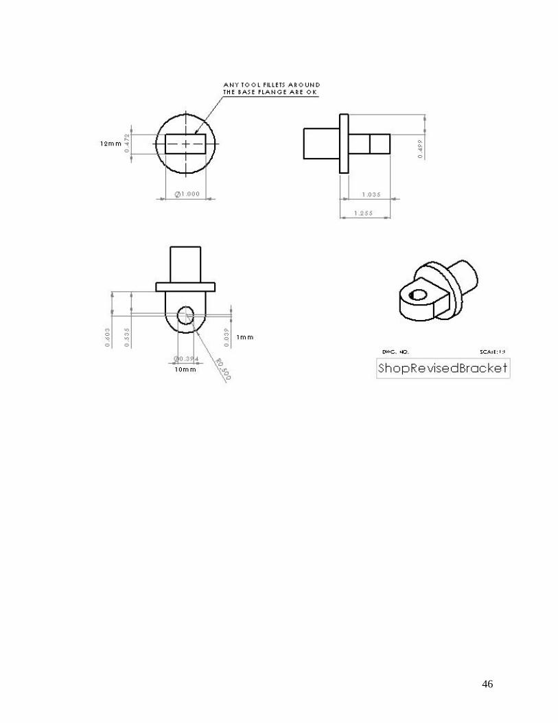
APPENDIX G – DETAIL DRAWINGS

44

45
46

47