realscan 7875-7000/8000 installation...
TRANSCRIPT

RealScan 7875-7000/8000 Installation Guide
16044
AIP-00342 Release C Aug 16, 2007
Information Products RSD-Atlanta

NCR RealScan 7875-7000/8000 Installation Guide
06/03 AIP-00342 Release B 2 of 56
The program products described in this book are licensed products of NCR Corporation. It is the policy of NCR to improve products as new technology, components, software, and firmware become available. Therefore, NCR reserves the right to change specifications without prior notice. All features, functions, and operations described herein may not be marketed by NCR in all parts of the world. Therefore, before using this document, consult your NCR representative or NCR office for information that is applicable and current.
NOTE: Connection of EPOS/PC terminals to weighing or measuring devices requires governmental approval before the connected devices can by placed into service for retail trade. Before connecting any NCR device to a retail weighing or measuring system contact the NCR, Weights and Measures Coordinator, Retail Atlanta to authenticate that NCR Certificates of Conformance/Approval are not infringed.

NCR RealScan 7875-7000/8000 Installation Guide
AIP-00342 Release B 06/03 3 of 56
Contents
Contents ..........................................................................................................................................3
Revision Record..............................................................................................................................5
Obtaining Additional Information ..................................................................................................5
Obtaining Technical Assistance......................................................................................................6
System Components .......................................................................................................................7 NCR Components ......................................................................................................................7 Sensormatic Components...........................................................................................................7
Step 1 – Verify and Prepare the Checkstand ..................................................................................8 Checkstand Cutout – RealScan 7875-7000/8000......................................................................8 Service Clearance.......................................................................................................................9 Item Diverter ..............................................................................................................................9 Ventilation Requirements.........................................................................................................10 Electrical Wiring to the Checkstand ........................................................................................11 Specific Checkstand Modifications..........................................................................................12 Sensormatic Equipment ...........................................................................................................12
Step 2 – Connect the Components ................................................................................................13 Install Sensormatic Antenna ....................................................................................................13 Connect Sensormatic Cables....................................................................................................14 Connect Remaining Components.............................................................................................15 Set the Communications Protocol Switch................................................................................16
Step 3 – Sensormatic Deactivation Setup .....................................................................................17 Power up the System................................................................................................................17 Specific Function Programming ..............................................................................................18
Step 4 – Install RealScan 7875 .....................................................................................................19 Install RealScan 7875...............................................................................................................19 Align the RealScan 7875 to the Checkstand ............................................................................20
Step 5 – Calibrate the Scale ..........................................................................................................22 Set Scale AC Voltage Frequency.............................................................................................22 Exercise the Scale ....................................................................................................................22 Access the Calibration Switch .................................................................................................23 Calibrate the Scale ...................................................................................................................24 Verify the Calibration ..............................................................................................................24 Secure the Calibration Switch..................................................................................................26
Step 6 – Set Program Parameters..................................................................................................27 Setting the Program Parameters ...............................................................................................27
Step 7 – Check the Scanner Operation .........................................................................................28 Scan Sample Tags ....................................................................................................................28 Check Sensormatic Deactivation System.................................................................................29 Call Sensormatic ......................................................................................................................29
Operating the Scanner...................................................................................................................30

NCR RealScan 7875-7000/8000 Installation Guide
06/03 AIP-00342 Release B 4 of 56
Operating the Scale.......................................................................................................................31
Operating the Sensormatic Deactivation System..........................................................................32 Normal Operation ....................................................................................................................32 Manual Deactivation ................................................................................................................33
Cleaning the RealScan 7875 .........................................................................................................34
Correcting Scanner Problems .......................................................................................................35
Correcting Scale Problems............................................................................................................36
Isolating Sensormatic Problems....................................................................................................37 Voice Messages........................................................................................................................37 Tones........................................................................................................................................37
Programming Worksheets.............................................................................................................38 1 0 – Communications Protocol...............................................................................................38 1 1 – Good Read Tone .............................................................................................................38 1 2 – Timers .............................................................................................................................39 1 3 – Bar Codes - 1 ..................................................................................................................39 1 4 – Bar Codes - 2 ..................................................................................................................40 1 5 – Bar Codes - 3 ..................................................................................................................41 1 7 – Bar Codes - 4 ..................................................................................................................41 1 8 – Bar Codes - 5 ..................................................................................................................42 1 6 – Label Identifiers ..............................................................................................................42 2 0 – RS-232 Parameters - 1 ....................................................................................................43 2 1 – RS-232 Parameters - 2 ....................................................................................................43 2 2 – RS-232 Prefix Byte .........................................................................................................44 2 3 – RS-232 Terminator Byte .................................................................................................44 2 4 – RS-232 Communications Options...................................................................................44 3 0 – Scale Parameters .............................................................................................................45 3 2 – Miscellaneous Parameters ...............................................................................................45 3 6 – Dual Cable Interface Options..........................................................................................45 ASCII Code Chart....................................................................................................................46
Appendix A – Pan-Oston PO-2 ....................................................................................................47
Appendix B – Pan-Oston PO-2.....................................................................................................48
Appendix C – Pan-Oston PO-4.....................................................................................................49
Appendix D – Regulatory Information .........................................................................................50 Federal Communications Commission (FCC) Radio Frequency Interference Statement.......50 Voluntary Control Council for Interference (VCCI) Radio Frequency Interference Statement50 Canadian Department of Communications Radio Frequency Interference Statement............50 Scale Regulatory ......................................................................................................................51 Declaration of Conformity .......................................................................................................52 Laser Safety .............................................................................................................................53

NCR RealScan 7875-7000/8000 Installation Guide
AIP-00342 Release B 06/03 5 of 56
Revision Record Date Issue Pages Remarks 05/13/03 A 1 though 54 First Printing 06/02/03 B 12, 17, 29, 33 Updated to latest Sensormatic requirements 8/16/2007 C 20 Updated scale alignment section
Obtaining Additional Information Other Information Products
Order Number Title 497-0001843 NCR RealScan 7875 Installation/Owner Guide B005-0000-1085 NCR RealScan 7875 User Guide B005-0000-1086 NCR RealScan 7875 Repair Guide BST0-2121-74 NCR Scanner Programming Tags BD20-1074-A NCR Scanner/Scale Interface Programmer's Guide
How To Obtain Information Products
Web Sites • http://inforetail.AtlantaGA.NCR.COM
(NCR only) • http://www.info.NCR.COM (Anyone) Online Order • Connect System (NCR only) Phone Order • 800-543-2010 (US area) • 622-3727 (VOICEplus) • 44-181-242-5350 (International) Fax Order • 937-445-6245 (US area)
44 (0) 20 8 242 5355 (International)
E-Mail • [email protected]
(US area) • [email protected]
R.COM (International) Mail Order • NCR Corporation IPP-Dayton
1529 Brown St. IPP EMD-2 Dayton, OH 45479 USA
• NCR Corporation 915 High Road North Finchley London N12 0HN United Kingdom

NCR RealScan 7875-7000/8000 Installation Guide
06/03 AIP-00342 Release B 6 of 56
Obtaining Technical Assistance Technical assistance is available as follows.
• Technical assistance in the United States: 1-800-262-7782 • Technical assistance in other countries: call your local NCR office • To order parts: 1-800-438-7830
Note: If you find any defective parts during installation of a new scanner, contact the Customer Satisfaction Hotline at one of the following.
• Phone: 1-800-528-8658 (USA) • Phone: 770-623-7400 (International) • E-mail: [email protected]
NCR RealScan 7875-7000/8000 Installation Guide
AIP-00342 Release B 06/03 7 of 56
System Components
NCR Components Following are the required NCR components.
• NCR RealScan 7875-7000/8000 • Power Supply with Power Cord • Interface Cable – appropriate for host terminal • Sensormatic Communications Cable – 1416-C841-030
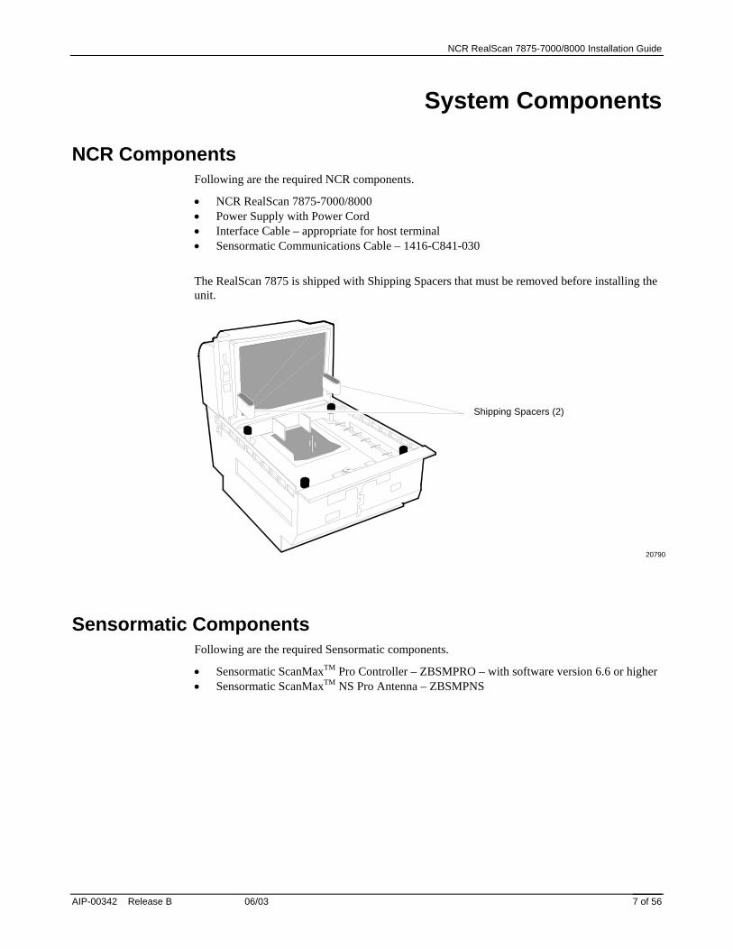
The RealScan 7875 is shipped with Shipping Spacers that must be removed before installing the unit.
20790
Shipping Spacers (2)
Sensormatic Components Following are the required Sensormatic components.
• Sensormatic ScanMaxTM Pro Controller – ZBSMPRO – with software version 6.6 or higher • Sensormatic ScanMaxTM NS Pro Antenna – ZBSMPNS

NCR RealScan 7875-7000/8000 Installation Guide
06/03 AIP-00342 Release B 8 of 56
Step 1 – Verify and Prepare the Checkstand
Checkstand Cutout – RealScan 7875-7000/8000
20551
GD D
H
I
A
B
E
C
C
D
A B C D E11 5/8 in.29.51 cm
20 1/16 in.50.95 cm
1 3/8 in.3.49 cm
3/8 in.0.95 cm
17 5/16 in.43.97 cm
7875-7200Scanner
12 1/16 in.30.63 cm
20 1/16 in.50.95 cm
1 3/8 in.3.49 cm
1/2 in.1.27 cm
17 5/16 in.43.97 cm
7875-8200Scanner/Scale
7875-7200Scanner
7875-8200Scanner/Scale
F G1 3/8 in.3.49 cm
7 1/8 in.18.1 cm
1 3/8 in.3.49 cm
7 1/8 in.18.1 cm
H I7 1/4 in.
18.42 cm7 1/4 in.
18.42 cm
Note: Dimension A for a 7875-7200 includes a spacer along each side of the unit so that it fits an existing 7870-2000 cutout.
Recommended shelf to catchRealScan 7875 if dropped during installation.
*
No electronics under RealScan 7875
C C
B
EF
A
F*
7 3/8 in.18.73 cm7 1/4 in.
18.42 cmNote: Dimension H includes a
Produce Guard.

NCR RealScan 7875-7000/8000 Installation Guide
AIP-00342 Release B 06/03 9 of 56
Service Clearance
Item Flow Area
20784
A = 20.3 cm (8 in.) minimum if checkstand structure is not removable for servicing.2.5 cm (1 in.) minimum if checkstand structure is removable for servicing.
B = 35.6 cm (14 in.) minimum if checkstand structure is not removable for servicing.17.8 cm (7 in.) minimum if checkstand structure is removable for servicing.
C = 18.1 cm (7 1/8 in.) minimum clearance to closest checkstand panel.The NCR 7875-7000/8000 must not be supported by a bottom panel.
Note: RealScan 7875-8000 units with a Produce Guard must have enough clearance to removethe Produce Guard for cleaning. The dimensions given here satisfy these requirements.
Mounting surface for keyboard must be removable for the following.• Servicing the unit.• Removing the 7875-8000 Produce Guard.• Replacing the vertical window.
B
C
A A
Item Diverter
Item Diverter(Must be removable to service Scanner/Scale in checkstand)
7.25 in. (18.4 cm)
14957
Note: The Item Diverter is not used in most self-checkout installations.

NCR RealScan 7875-7000/8000 Installation Guide
06/03 AIP-00342 Release B 10 of 56
Ventilation Requirements The RealScan 7875 is designed to operate without an exhaust fan in the checkstand; however, there must be adequate convection airflow. The ambient temperature inside the checkstand cannot be higher than 40° C (104° F). Also, the ambient temperature inside the checkstand cannot be higher than 7° C (12.6° F) above the ambient temperature outside the checkstand. For example, if the ambient temperature outside the checkstand is 24.4° C (76° F), the ambient temperature inside the checkstand cannot be greater than 31.4° C (88.6° F). If the checkstand contains other heat producing equipment, you may need to use forced air to keep the temperature within the specified range. However, air coming into or leaving the checkstand MUST NOT enter or exit past the RealScan 7875.

NCR RealScan 7875-7000/8000 Installation Guide
AIP-00342 Release B 06/03 11 of 56
Electrical Wiring to the Checkstand
Feeder wiring and insulated ground frommain service panel to distribution panelto be run in metal conduit.
The electrical wiring must meet allelectrical codes, laws, and regulations.
Note:
Circuit Breakers
NCR circuits should be run inseparate metal Conduits.
Isolated/InsulatedGround Bus
Isolated Ground Receptacles
Neutral andGround Bus
NeutralBus
InputVoltage
Input Voltage L1, L2 Circuit BreakersU.S., Canada, &Japan
European
International
100Vac to 120Vac
220Vac
220Vac to 240Vac
100Vac to 120Vac
220Vac
220Vac to 240Vac
Standard single-pole; valuedetermined by type of devicebranch and by electrical code.
European double-pole.
Circuit B: Terminal
Installation Type
NCR circuits must be dedicated toNCR equipment or other logicallyconnected electronic equipment(modems, DAA, bridges, etc.)
Note:
Circuit C: Scanner/ScaleReceptacle should be easilyaccessible and near theScanner/Scale
L2
L3
Distribution Panel
Main ServicePanel
Conduit
CheckstandFrame
Circuit A: Checkstand
BeltMotor
Belt ControlLighting
Misc. Equip.NG
L1
R0121
Note: The RealScan 7875 outlet in the checkstand must be connected to a circuit breaker switch. This switch must be located close to the operator and is used as the On/Off switch for the RealScan 7875.
NCR RealScan 7875-7000/8000 Installation Guide
06/03 AIP-00342 Release B 12 of 56
Specific Checkstand Modifications A few checkstands require some modification. Appendices are included for these different types of checkstands. If modifications are needed, refer to the appendix that matches your installation. After making any necessary modifications, continue to step 2 on the next page.
• Appendix A – Pan-Oston PO-2 • Appendix B – Pan-Oston PO-3 • Appendix C – Pan-Oston PO-4
Sensormatic Equipment • Plug the power cord of the Sensormatic ScanMaxTM Pro into an ac outlet not dedicated to
POS equipment. Plug into an unswitched ac outlet with less than 0.5Vac between neutral and ground. Electrical Primary input: 100-120/200-240Vac, 50-60 Hz ±5%, 1Arms maximum.
• Do Not connect through generator or Uninterruptible Power Supply (UPS). • Keep the power cord and antenna cable away from cash drawers and other items whose
operation may pinch or otherwise damage them. Failure to do so can damage equipment or injure people nearby.
• Do not plug or unplug ANY Sensormatic ScanMaxTM Pro Controller cables with power on. • If mounting the controller to the sidewall of a counter, its cable connectors cannot face up. • Deactivator Interacting with Other Devices: Isolate ScanMax Pro controller from neon
signs, motors, computers, cash registers, terminals, or data communications equipment. Computer monitors, TVs, switching power supplies and neon displays can affect deactivator operation. Keep the Sensormatic ScanMaxTM NS Pro Antenna away from these devices whenever possible.
• Environmental: Operating temperature 0 to 40°C (32° to 104°F) / Non-operating temperature -40° to 70°C (-40° to 158°F)
NCR RealScan 7875-7000/8000 Installation Guide
AIP-00342 Release B 06/03 13 of 56
Step 2 – Connect the Components
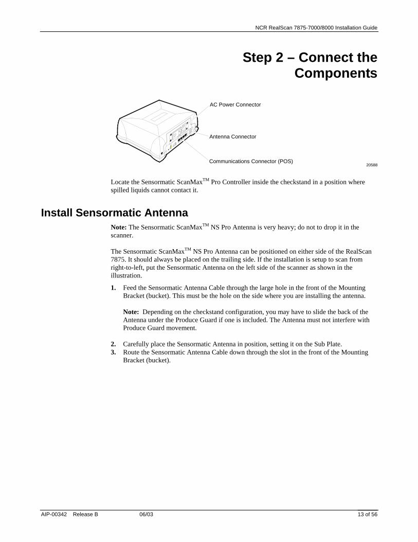
20588
Antenna Connector
Communications Connector (POS)
AC Power Connector
Locate the Sensormatic ScanMaxTM Pro Controller inside the checkstand in a position where spilled liquids cannot contact it.
Install Sensormatic Antenna Note: The Sensormatic ScanMaxTM NS Pro Antenna is very heavy; do not to drop it in the scanner.
The Sensormatic ScanMaxTM NS Pro Antenna can be positioned on either side of the RealScan 7875. It should always be placed on the trailing side. If the installation is setup to scan from right-to-left, put the Sensormatic Antenna on the left side of the scanner as shown in the illustration.
1. Feed the Sensormatic Antenna Cable through the large hole in the front of the Mounting Bracket (bucket). This must be the hole on the side where you are installing the antenna. Note: Depending on the checkstand configuration, you may have to slide the back of the Antenna under the Produce Guard if one is included. The Antenna must not interfere with Produce Guard movement.
2. Carefully place the Sensormatic Antenna in position, setting it on the Sub Plate. 3. Route the Sensormatic Antenna Cable down through the slot in the front of the Mounting
Bracket (bucket).

NCR RealScan 7875-7000/8000 Installation Guide
06/03 AIP-00342 Release B 14 of 56
20574
Sensormatic Antenna Cable
Sensormatic Antenna
Connect Sensormatic Cables The Sensormatic Antenna Cable and the Sensormatic Communications Cable go between the RealScan 7875 and the ScanMaxTM Pro Controller. Be sure to route these cables through the cutout in the checkstand.
1. Connect the Sensormatic Antenna Cable to the Antenna connector on the ScanMaxTM Pro Controller.
2. Connect one end of Sensormatic Communications Cable to one of the RS-232 Peripheral Ports on the RealScan 7875 and the other end to the POS connector on the ScanMaxTM Pro Controller.
20592
RealScan 7875
SensormaticCommunications Cable
SensormaticAntennaCable
ScanMax™ Pro Controller
ACPowerCord
BCAN I/O POS SERVICE REMOTE ANTENNAEXPANSIONBR
MNS
PROGSTATUS

NCR RealScan 7875-7000/8000 Installation Guide
AIP-00342 Release B 06/03 15 of 56
Connect Remaining Components Locate the NCR RealScan 7875 Power Supply in position in the checkstand where spilled liquid cannot contact it. The system configuration may also include a Remote Display and an RS-232 peripheral such as a hand-held scanner. The following illustration shows how all cables are connected. Be sure to route these cables properly through the checkstand. After all cables are connected, plug in the NCR RealScan 7875 and the Sensormatic ScanMaxTM Pro Controller Power Cords to supply power to the units.
20553
DC
POW
ER
REM
OTE
DIS
PLA
Y5A
MA
X
SCA
NN
ER
Check switch settings
5V
DCPower Cable
RemoteDisplay
ACPowerCord
PowerSupply RealScan 7875
InterfaceCable
HostTerminal RS-232
Peripheral
BCAN I/O POS SERVICE REMOTE ANTENNAEXPANSIONBR
MNS
PROGSTATUS
PORT 1 PORT 2
DUAL PERIPHERAL PORTS
SensormaticScanMax™ Pro Controller
SensormaticCommunications Cable
SensormaticAntennaCable
AC PowerCord
NCR RealScan 7875-7000/8000 Installation Guide
06/03 AIP-00342 Release B 16 of 56
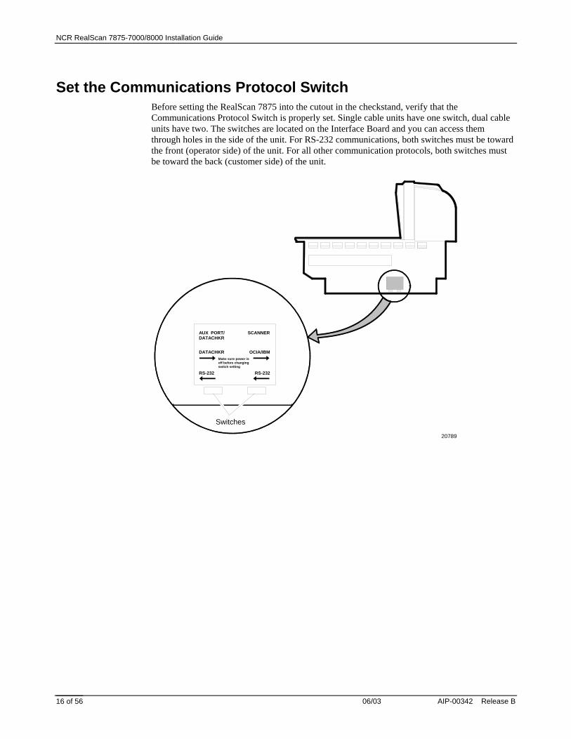
Set the Communications Protocol Switch Before setting the RealScan 7875 into the cutout in the checkstand, verify that the Communications Protocol Switch is properly set. Single cable units have one switch, dual cable units have two. The switches are located on the Interface Board and you can access them through holes in the side of the unit. For RS-232 communications, both switches must be toward the front (operator side) of the unit. For all other communication protocols, both switches must be toward the back (customer side) of the unit.
20789
AUX PORT/DATACHKR
SCANNER
DATACHKR OCIA/IBM
RS-232 RS-232
Make sure power isoff before changingswitch setting
Switches

NCR RealScan 7875-7000/8000 Installation Guide
AIP-00342 Release B 06/03 17 of 56
Step 3 – Sensormatic Deactivation Setup
Power up the System Note: Refer to the Sensormatic ScanMax™ Pro Controller documentation for additional information about setting up the controller.
1. Turn on the NCR RealScan 7875. When the RealScan 7875 is first turned on, all the Sensormatic parameters should be at their default settings. • RealScan 7875 Scan tone delay until deactivation = Enabled • RealScan 7875 Deactivation button = Disabled • RealScan 7875 Clicking = Enabled The RealScan 7875 should give the voice message EAS Offline if the Sensormatic ScanMaxTM Pro Controller is still turned off. Also, the Red Status Indicator flashes rapidly.
2. Turn on the Sensormatic ScanMaxTM Pro Controller. This system is programmed at the factory with default settings for proper operation.
3. After the RealScan 7875 and the Sensormatic ScanMaxTM Pro Controller have both been on for about 15 seconds, the RealScan 7875 should give the voice message EAS Online. Note: Voice message EAS Online must be given before you can continue. If voice message EAS Online is not given, turn off the power to all components. Check all cable connections then repeat this procedure starting at step 1. If voice message EAS Online is still not given and the Red Status Indicator is flashing rapidly, scan the Reset programming tag. If the status given is still EAS Offline, follow instructions on the Sensormatic Card – Before You Call About… The problem may be a bad Antenna cable.
4. Position a Hard Tag over the top of the RealScan 7875. As you move the Hard Tag, the RealScan 7875 should start clicking when the tag moves within 4 inches of the center of the Top Plate. If the clicking sound is not generated, scan the Reset programming tag, then go to step 3. If the second attempt fails, call for help. Refer to Obtaining Technical Assistance.

NCR RealScan 7875-7000/8000 Installation Guide
06/03 AIP-00342 Release B 18 of 56
Specific Function Programming There are several Sensormatic Security Tag Deactivation functions that can be programmed at the RealScan 7875.
Security Tag Deactivation
This parameter enables or disables the entire Sensormatic Deactivation function.
Enable Security Tag Deactivation Programming Mode, Hex 4, Hex 2, Hex B, Save and Reset.
Disable Security Tag Deactivation Programming Mode, Hex 4, Hex 2, Hex A, Save and Reset.
Security Tag Detected Tone
This parameter enables or disables a tone while a security tag is being detected. When enabled and a security tag is within the detection zone, a continuous beeping tone is produced that sounds similar to a Geiger counter.
Enable Security Tag Detected Tone Programming Mode, Hex 6, Hex 2, Hex D, Save and Reset.
Disable Security Tag Detected Tone Programming Mode, Hex 6, Hex 2, Hex C, Save and Reset.
Deactivated Tone
This parameter enables or disables a tone following a security tag deactivation.
Enable Security Tag Deactivated Tone Programming Mode, Hex 4, Hex B, Hex B, Save and Reset.
Disable Security Tag Deactivated Tone Programming Mode, Hex 4, Hex B, Hex A, Save and Reset.
Deactivated Tone Type
This parameter determines the type of tone to produce when a security tag is deactivated.
Series of Tones Programming Mode, Hex 4, Hex B, Hex E, Save and Reset.
Single Long Tone Programming Mode, Hex 4, Hex B, Hex F, Save and Reset.
Deactivated Tone Frequency and Length
The Deactivated Tone frequency and length can be adjusted by scanning the appropriate tags. Each time you scan the Deactivated Tone Frequency tag the tone frequency increases until it reaches a maximum level. At this point the cycle continues from the lowest level. Each time you scan the Deactivated Tone Length tag the tone length increases until it reaches a maximum time. At this point the cycle continues from the shortest time.

NCR RealScan 7875-7000/8000 Installation Guide
AIP-00342 Release B 06/03 19 of 56
Step 4 – Install RealScan 7875
Install RealScan 7875 Note: Refer to the NCR FastLane 7342 Hardware Installation Guide (B005-0000-1370) for the most current information about how to install a RealScan 7875-7000/8000 and the Sensormatic components into an NCR FastLane checkstand.
1. Grasp the RealScan 7875 as shown and lower it into the checkstand cutout. Be careful not to
damage any of the cables. Note: It is important that the RealScan 7875 does not rock on its supports. Make sure that all adjustable supports are securely fastened and that the RealScan 7875 is sitting on all supports.
20590D 2. After the unit is properly sitting on its supports, install the Produce Guard if one is present.
The Produce Guard mounts on the two back Top Plate Support Posts. 3. Install the Top Plate.

NCR RealScan 7875-7000/8000 Installation Guide
06/03 AIP-00342 Release B 20 of 56
20571B
Top Plate
Align the RealScan 7875 to the Checkstand The measurements in this section refer to efficiency of scanning, by eliminating exposed edges which would catch a product during the recommended “power slide” scanning technique thus slowing down the cashier. Scaling requirements are quite separate and less vigorous, per the section above: “Install RealScan 7875”.
FOR EFFICIENT SCANNING:
The leading edge of the Top Plate must be flush or up to 1/16 in. (0.15 cm) below the top of the checkstand. The trailing edge of the Top Plate must be flush or up to 1/16 in. (0.15 cm) above the top of the checkstand.
Note: The four adjustable support posts on the Scale Support Bar Assembly are set at the factory. Do not attempt to adjust the Top Plate using these posts. Adjust the checkstand supports to align the Top Plate with the checkstand.
If the Top Plate is properly aligned with the checkstand, an item should easily slide from the checkstand onto the Top Plate and then from the Top Plate onto the checkstand. The following illustration shows this alignment.

NCR RealScan 7875-7000/8000 Installation Guide
AIP-00342 Release B 06/03 21 of 56
14961
Correct Alignment
Bad AlignmentScanner Too High
Bad AlignmentScanner Too Low
High SurfaceLow SurfaceHigh SurfaceLow Surface
NCR RealScan 7875-7000/8000 Installation Guide
06/03 AIP-00342 Release B 22 of 56
Step 5 – Calibrate the Scale Note: You MUST calibrate the scale when you install a RealScan 7875-80xx. To be in compliance with governmental weights and measures regulations, you must be certified to calibrate the scale.
Note: Calibration information is NOT sent to the host terminal. If your RealScan 7875 does not have voice enabled or does not have a remote display, you must use a Field Service Calibration Display.
Note: Be sure the Interface Cable between the RealScan 7875 and the host terminal is disconnected during scale calibration. Some host terminals can cause interference that can invalidate the scale calibration.
You can calibrate the scale after power has been supplied for 30 minutes if the ambient temperature has been 20° C (68° F) for at least 24 hours. If this condition is not met, then the scale must be on for at least 6 hours before you can calibrate it. Also, you must use a certified weight set to calibrate and certify the scale.
The RealScan 7875 maintains an audit trail of scale calibration and programming activity. The audit trail records the number of times the scale has been calibrated. You can display the audit trail count on a Remote 7825 or Field Service Calibration Display by pressing the Scale Zero Button on the Operator Display Panel. The display alternates between Cal xxx and PAr xxx.
Set Scale AC Voltage Frequency The RealScan 7875-8000 units contain a scale that must be set for the correct AC voltage frequency before the scale is calibrated.
1. Turn on the AC Power by turning on the circuit breaker. 2. Set the AC voltage frequency by scanning the following sequence of programming tags.
These must be the first tags scanned after applying power to the unit.
60 Hz AC Voltage Programming Mode, Hex 3, Hex 0, Hex F – Default setting 50 Hz AC Voltage Programming Mode, Hex 3, Hex 0, Hex E
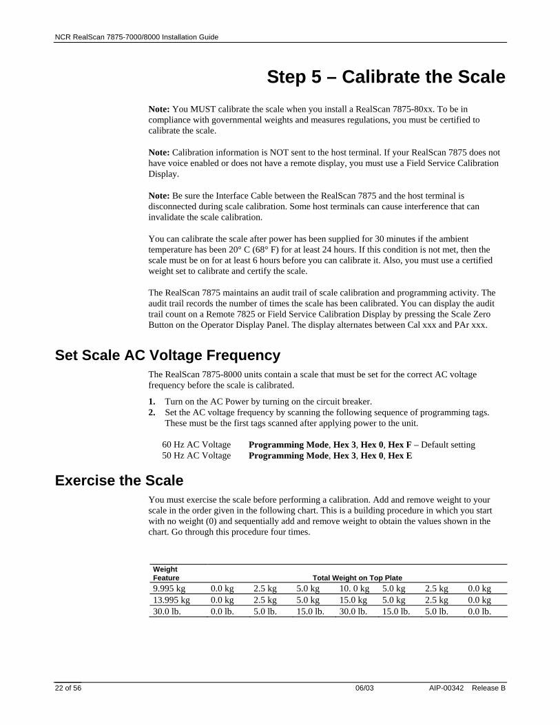
Exercise the Scale You must exercise the scale before performing a calibration. Add and remove weight to your scale in the order given in the following chart. This is a building procedure in which you start with no weight (0) and sequentially add and remove weight to obtain the values shown in the chart. Go through this procedure four times.
Weight Feature
Total Weight on Top Plate
9.995 kg 0.0 kg 2.5 kg 5.0 kg 10. 0 kg 5.0 kg 2.5 kg 0.0 kg 13.995 kg 0.0 kg 2.5 kg 5.0 kg 15.0 kg 5.0 kg 2.5 kg 0.0 kg 30.0 lb. 0.0 lb. 5.0 lb. 15.0 lb. 30.0 lb. 15.0 lb. 5.0 lb. 0.0 lb.

NCR RealScan 7875-7000/8000 Installation Guide
AIP-00342 Release B 06/03 23 of 56
Access the Calibration Switch The Calibration Switch is located below the Top Plate. Remove the Top Plate.
The RealScan 7875-80xx does not have a plastic Calibration Switch Cover. Do not remove the Produce Guard if one is present.
Remove the screw that secures the Calibration Switch Security Cover. Also remove the seal if one is present. Rotate the Calibration Switch Cover to gain access to the Calibration Switch.
Screw
Wire Seal
Calibration SwitchSecurity Cover
20587
Calibration Switch

NCR RealScan 7875-7000/8000 Installation Guide
06/03 AIP-00342 Release B 24 of 56
Calibrate the Scale 1. Press the Scale Zero Button to display the Cal and PAr values. Record these values. 2. Install the Produce Guard if one is included then install the Top Plate. Raise the front edge
of the Top Plate enough to access the Calibration Switch and press it, then quickly lower the Top Plate. The display should show Ready C-00 kg (00 lb.).
3. Follow the sequence of steps in the following chart.
Display Add Weight Remove Weight Ready C-2.5 kg (05 lb.) 2.50 kg (5.00 lb.) Ready C-05 kg (15 lb.) 2.50 kg (10.00 lb.) Ready C-10 kg (30 lb.) 5.00 kg (15.00 lb.) Ready C-00 kg (00 lb.) 10.00 kg (30.00 lb.) Ready 0.000 kg (0.00 lb.)
Verify the Calibration The scale accuracy test meets government requirements of testing the accuracy of the scale after performing a scale calibration. It contains a series of four tests that must be run in the continuous sequence given.
Increasing Load Test This test checks the scale’s accuracy when incrementally adding weight to the center of the top plate. Use weights that correspond to the RealScan 7875 weight feature.
Step Weight Feature Add Weight Remove Weight Display Result 1 9.995 kg 0.1 kg 0.1 ± 0.00 kg 13.995 kg 0.1 kg 0.1 ± 0.00 kg 30.0 lb. 0.2 lb. 0.2 ± 0.00 lb. 2 9.995 kg 2.5 kg 0.1 kg 2.5 ± 0.00 kg 13.995 kg 2.5 kg 0.1 kg 2.5 ± 0.00 kg 30.0 lb. 5.0 lb. 0.2 lb. 5.0 ± 0.00 lb. 3 9.995 kg 2.5 kg 5.0 ± 0.005 kg 13.995 kg 4.5 kg 7.0 ± 0.005 kg 30.0 lb. 5.0 lb. 10.0 ± 0.01 lb. 4 9.995 kg 2.5 kg 7.5 ± 0.005 kg 13.995 kg 3.0 kg 10.0 ± 0.005 kg 30.0 lb. 10.0 lb. 20.0 ± 0.01 lb. 5 9.995 kg 2.495 kg 9.995 ± 0.005 kg 13.995 kg 3.995 kg 13.995 ± 0.005 kg 30.0 lb. 10.0 lb. 30.0 ± 0.01 lb.
Note: Do NOT remove any weight from the Top Plate.

NCR RealScan 7875-7000/8000 Installation Guide
AIP-00342 Release B 06/03 25 of 56
Over-Capacity Test This test checks for the proper indication from the scale when too much weight is placed on the top plate.
Note: This test must immediately follow the increasing load test; do not remove any of the weights prior to running this test.
Place additional weight on the top plate as shown in the following chart. Use the weight that corresponds to the RealScan 7875 weight feature. The display shows a series of dashes to indicate an over-capacity condition.
Step Weight Feature Add Weight Remove Weight Display Result 1 9.995 kg 0.04 kg --.--- 13.995 kg 0.04 kg --.--- 30.0 lb. 0.08 lb. --.--- 2 9.995 kg 0.04 kg 9.995 ± 0.005 kg 13.995 kg 0.04 kg 13.995 ± 0.005 kg 30.0 lb. 0.08 lb. 30.0 ± 0.01 lb.
Note: Remove only the "over capacity" weights before proceeding.
Decreasing Load Test This test checks the scale’s accuracy when incrementally removing weight from the top plate. Use weights that correspond to the RealScan 7875 weight feature.
Note: This test must immediately follow the over-capacity test; do not remove any of the weights prior to running this test.
Step Weight Feature Add Weight Remove Weight Display Result 1 9.995 kg 2.495 kg 7.5 ± 0.005 kg 13.995 kg 3.995 kg 10.0 ± 0.005 kg 30.0 lb. 10.0 lb. 20.0 ± 0.01 lb. 2 9.995 kg 5.0 kg 2.5 ± 0.00 kg 13.995 kg 7.5 kg 2.5 ± 0.00 kg 30.0 lb. 15.0 lb. 5.0 ± 0.00 lb. 3 9.995 kg 0.1 kg 2.5 kg 0.1 ± 0.00 kg 13.995 kg 0.1 kg 2.5 kg 0.1 ± 0.00 kg 30.0 lb. 0.2 lb. 5.0 lb. 0.2 ± 0.00 lb. 4 9.995 kg 0.1 kg 0.0 ± 0.00 kg 13.995 kg 0.1 kg 0.0 ± 0.00 kg 30.0 lb. 0.2 lb. 0.0 ± 0.00 lb.

NCR RealScan 7875-7000/8000 Installation Guide
06/03 AIP-00342 Release B 26 of 56
Shift Test This test involves moving a weight off the center point of the top plate to check for continued accuracy.
1. Place 5.00 kg (15.00 lb.) of weight in position 1 on the Top Plate. 2. Move the weight to position 2 on the Top Plate. The display should show 5.00 ± 0.005 kg
(15.00 ± 0.01 lb.). 3. Repeat step 2 for positions 3, 4, and 5. 4. Move the weight to position 1 again. 5. Remove all weights. The display should read 0.000 ± 0.000kg (0.00 ± 0.00 lb.). 6. Press the Scale Zero Button. Record the Cal and PAr values shown on the display.
14967
1
2
34
5
Secure the Calibration Switch Remove the Top Plate. Rotate the Calibration Switch Security Cover into position and install the screw.
When you perform a scale calibration, someone must seal the Calibration Switch Security Cover. This may be done with a Lead/Wire Seal (NCR part number 603-8001097) using a Lead/Wire Seal Press (NCR part number 603-9000157) or a Film/Paper seal (obtained locally). The type of seal you use depends on your local laws; also, Weights and Measures officials may be required to attach the seal.
NOTE: In the United States and Canada, the audit trail can serve as an acceptable security seal if an NCR 7825 Display is used as the weight display.
After securing the Calibration Switch, if the unit is a RealScan 7875-2000, install the plastic Calibration Switch Cover and the Produce Guard if included. Install the Top Plate.

NCR RealScan 7875-7000/8000 Installation Guide
AIP-00342 Release B 06/03 27 of 56
Step 6 – Set Program Parameters Now you need to make any necessary programming changes to the RealScan 7875. The RealScan 7875 does not have an On/Off switch. Use the circuit breaker switch in the checkstand that supplies power to the unit as the On/Off switch.
Setting the Program Parameters Caution: Some host terminals can corrupt the RealScan 7875 program if they are running and are connected to the RealScan 7875 while you are making program changes. Either turn off the host terminal or disconnect the interface cable before scanning any programming tags.
To make changes to the program parameters, enter information from the Programming Worksheets located toward the back of this book. The Programming Worksheets identify all the available program parameters. Each worksheet relates to a specific programming mode. Most programming options have defaults, identified by a heavy box, which are determined at the factory. Scanning the Default tag as the first tag after applying power to the unit sets the parameters to these values.
Changing the RealScan 7875 program is accomplished by scanning the proper sequence of programming tags. Following are three major steps for making program changes.
1. Enter the Base Programming State by scanning the Programming Mode tag; must be first tag scanned after applying power.
2. Select a Programming Worksheet and enter its parameter data by scanning the appropriate Hex tags.
3. Save the program by scanning the Save and Reset tag.
Note: In most cases the factory determined defaults are the correct parameter setting. However, if you do need to make changes, it is recommended that you first set all parameters to default values then make any necessary changes to the appropriate parameters.

NCR RealScan 7875-7000/8000 Installation Guide
06/03 AIP-00342 Release B 28 of 56
Step 7 – Check the Scanner Operation
Scan Sample Tags Now you should scan some sample tags to verify that the RealScan 7875 is communicating with the host terminal. Following are four good tags that you can use; however, the RealScan 7875 must be programmed to read these tags. The defaults are UPC-A enabled and the others disabled.
UPC-A
1 7 7 06 2 3 7 92 0 4
Code 39
1 7 7 0 6 2 3 7 9 2 0
Code 128
1 7 7 0 6 2 3 7 9 2 0
Interleaved 2 of 5
0 1 7 7 0 6 2 3 7 9 2 0

NCR RealScan 7875-7000/8000 Installation Guide
AIP-00342 Release B 06/03 29 of 56
Check Sensormatic Deactivation System Position a Hard Tag above the RealScan 7875 Top Plate. As you move the tag within 4 inches of the Top Plate you should hear a clicking sound. If the Hard Tag is less than 4 inches from the Top Plate, consult the Sensormatic Card – Before You Call About…
20788
X Axis Orientation4" Above Top Plate
Y Axis Orientation4" Above Top Plate
Next, obtain a security tag that has not been deactivated. Scan a bar code and immediately pass the security tag through the deactivation zone. The Good Read Tone should sound indicating a good read of the barcode and deactivation of the security tag. Refer to the Operating the Sensormatic Deactivation System section for detailed operating instructions.
Call Sensormatic If you chose to purchase an EAS component from NCR with your NCR Scanner/Scale, please be aware that the EAS device requires on-site testing and tuning by your EAS supplier who performs this service for a fee. If your NCR Scanner/Scale does not include an EAS device and you wish to add one after your scanner purchase, you must purchase the EAS device and testing and tuning services from your EAS supplier.
Please contact your Sensormatic representative or call 1 (800) 241-6678.

NCR RealScan 7875-7000/8000 Installation Guide
06/03 AIP-00342 Release B 30 of 56
Operating the Scanner The RealScan 7875 is a fixed position device that is installed in a checkout counter. It is not handled or moved by the operator during operation. The RealScan 7875 is maintained and serviced by trained service personnel only. The operator has no access to any laser module components.
The RealScan 7875 does not have a power switch. However, you turn it on and off by using the circuit breaker switch, located in the checkstand, that supplies power to the unit. Be sure this switch is in the On position.
The Status Indicator on the Operator Display Panel is Red when the RealScan 7875 is ready. The correct way to scan is to slide an item from the checkstand, across the scanner, and back onto the checkstand. With a good scan, the Status Indicator Flashes Green, then turns Red. Nothing happens if the bar code is not read.
14966
Status Indicator

NCR RealScan 7875-7000/8000 Installation Guide
AIP-00342 Release B 06/03 31 of 56
Operating the Scale The RealScan 7875 typically takes from 1.0 to 2.0 seconds to weigh an item, depending on the item’s weight. The heavier the item, the longer it takes. Before weighing an item, make sure the scale display is displaying all zeros. If not, press the Scale Zero Button.
Note: The item you are weighing should be placed in the center of the Top Plate. Make sure the item does not overhang onto the checkstand; whatever is weighed must fit fully on the Top Plate. If the RealScan 7875 includes the Produce Guard, larger items may rest against it.
When the scale weighs an item, the Status Indicator flashes Green and a good weigh tone is sounded. Nothing happens if the scale cannot weigh an item.
Status Indicator
Scale Zero Button
Integrated Display
16048
Top Plate

NCR RealScan 7875-7000/8000 Installation Guide
06/03 AIP-00342 Release B 32 of 56
Operating the Sensormatic Deactivation System
Normal Operation The operating procedures can vary according to the parameter settings. The following procedure assumes the Sensormatic parameters are set to the following values.
• Security tag deactivation function is enabled. • Security tag deactivated tone is enabled. • Security tag detected tone is enabled.
Following procedure assumes the RealScan 7875 and the Sensormatic ScanMax™ Pro Controller are turned on and functioning properly.
1. Pass an item across the scanner. 2. As the barcode goes through the scan zone, the RealScan 7875 reads it. 3. As the security tag goes through the Sensormatic deactivation zone, the Sensormatic system
deactivates the security tag. At this time the NCR RealScan 7875 sounds the Good Read Tone.
4. If the security tag is not deactivated, a clicking tone is generated. Place the item against the gray label. The clicking tone stops when the security tag is deactivated.
Note: The security tag must be detected by the Sensormatic system before the Scan Enable Timer expires or it is not deactivated even when it does come into the deactivation zone. In this case, the Security Tag Detected Tone sounds while the tag is in the deactivation zone. The sound is similar to a Geiger counter. When this condition occurs, the security tag must be deactivated manually.

NCR RealScan 7875-7000/8000 Installation Guide
AIP-00342 Release B 06/03 33 of 56
Manual Deactivation If for some reason the security tag is not deactivated in the normal manner, it can be deactivated manually. This normally occurs when too much time elapses after the RealScan 7875 reads the barcode. Use the following procedure to deactivate the security tag.
1. Press the Volume button on the RealScan 7875. The RealScan 7875 laser light turns off, disabling the scanner.
2. Pass the security tag into the deactivation zone. The Security Tag Detected Tone sounds (similar to a Geiger counter) and the tag is deactivated. The RealScan 7875 laser light turns on, enabling the scanner.

NCR RealScan 7875-7000/8000 Installation Guide
06/03 AIP-00342 Release B 34 of 56
Cleaning the RealScan 7875 Keeping the scan windows clean helps keep the read rate exceptionally high. During normal operation the scan windows get dirty, and if you permit the dirt to accumulate, performance degrades to the point where the scanner cannot read bar codes. The Please Clean Window indicator flashes when the scan windows need cleaning. Use a soft cloth moistened with a common, non-abrasive, liquid window cleaner to clean the scan windows. Be sure to spray the cleaner onto the cloth, not directly onto the RealScan 7875
Note: Scale problems can occur from debris collecting under the Top Plate. Be sure to keep the plastic Subplate clean to prevent interference with the Top Plate when weighing items. Debris can also collect behind and under the Produce Guard. Keep this area clean, which requires removing the Produce Guard.
16049
Top Plate
Plastic SubplateWiping Action

NCR RealScan 7875-7000/8000 Installation Guide
AIP-00342 Release B 06/03 35 of 56
Correcting Scanner Problems Problem
Status Indicator
Tone
Possible Cause Corrective Action
Scanner does not operate
Red Off Green Off
Off No power to the unit
Check electrical outlet for proper power.
Scanner does not operate
Red Flashing Green Flashing
Off Sleep mode Pass anything in front of the Motion Detector.
Scanner does not operate
Red Flashing Green Off
Off Communications is IBM 468x and scanner is off-line
• Verify that the IBM terminal is turned on.
• Verify that the IBM terminal is recognizing the RealScan 7875.
• Verify that the Interface Cable is properly connected.
Scanner does not read tags
Red Flashing Green Off
Off Internal failure Remove power from the RealScan 7875 and then supply power again. If the problem is not corrected, have scanner repaired.
Scanner reads only two tags
Red On Green Off
Off RealScan 7875 not communicating with host terminal
• Verify that the Interface Cable is properly connected.
• Remove power from the RealScan 7875 and then supply power again. If the problem is not corrected, have scanner or host terminal repaired.

NCR RealScan 7875-7000/8000 Installation Guide
06/03 AIP-00342 Release B 36 of 56
Correcting Scale Problems Problem Possible Cause Corrective Action Error code 5---- displays
Scale drift Verify that nothing is on the scale. Lift the Top Plate and verify that no objects are under it. Push Scale Zero button. If error code persists, have unit repaired.
Error code 4---- displays
Possible scale error Press Scale Zero button and retry. If error code persists, have unit repaired.
Error code 4---- displays
Slight vibration to scale when calibrating
Calibrate scale, being sure not to permit any external scale movement while the weights are on the scale.
Scale display is blank
Top Plate is being prevented from moving down.
• Remove interference around edge of Top Plate and checkstand.
• Remove any foreign objects from under the Top Plate.

NCR RealScan 7875-7000/8000 Installation Guide
AIP-00342 Release B 06/03 37 of 56
Isolating Sensormatic Problems
Problem Possible Cause Corrective Action Does not deactivate tags
Sensormatic ScanMax™ Pro Controller not turned on.
Check the On/Off switch on the ScanMax™ Pro Controller for being on.
Does not deactivate tags
Sensormatic ScanMax™ Pro Controller is not properly programmed.
Scan Restore Sensormatic Parameters tag.
Does not deactivate tags
Improper cable connection. • Assure the Sensormatic ScanMaxTM NS Pro Antenna Cable is properly connected to the ScanMax™ Pro Controller.
• Assure that the Sensormatic Communications Cable is properly connected to one of the RS-232 Peripheral Ports on the back of the RealScan 7875 and to the POS connector on the ScanMax™ Pro Controller.
Does not deactivate tags
Faulty Sensormatic Interlock Cable
• Replace the Sensormatic Interlock Cable
Does not deactivate tags
Faulty Sensormatic ScanMaxTM NS Pro Antenna or Antenna Cable.
Replace Sensormatic Sensormatic ScanMaxTM NS Pro Antenna.
Does not deactivate tags
Faulty Controller Replace Sensormatic ScanMax™ Pro Controller
The RealScan 7875 uses audio messages to identify the Sensormatic deactivation status. This includes voice messages and tones.
Voice Messages • EAS Online – Given when the Sensormatic ScanMax™ Pro Controller is turned on if it is
operational and properly connected to the RealScan 7875. • EAS Offline – Given when the Sensormatic ScanMax™ Pro Controller is turned off, has
become non-operational, or becomes disconnected from the RealScan 7875. • EAS Online Mode One – Given if the parameters in the Sensormatic ScanMax™ Pro
Controller do not match those in the RealScan 7875.
Tones • Deactivated Tone – During normal operation, the RealScan 7875 can sound a tone when a
tag is deactivated. This feature can be turned on or off with programming tags. The frequency, length, and type can also be programmed.
• Security Tag Detected – When passing an active tag around the Sensormatic Antenna, the RealScan 7875 produces a clicking tone similar to a Geiger counter. This can be used to check the size of the detection zone. This can also be turned on or off with programming tags.

NCR RealScan 7875-7000/8000 Installation Guide
06/03 AIP-00342 Release B 38 of 56
Programming Worksheets
1 0 – Communications Protocol Protocol
OCIANCR Long
IBMSlot Scanner
OCIANon NCR
Dual Cable
OCIASingle Cable
RS-232
CasioDual Cable
OCIA NCRDual Cable
IBMHand-HeldBar CodeReader
0OCIA
NCR Short(Datachecker)
IBM 1520 Bar CodeReader
TECDual Cable
IBM USB
14391
1 2 3 4 5
6 7 A B C D
E 0
NCR (RS-232) USB
1 1 – Good Read Tone Tone On/OffA
Off
0
On
ToneFrequency(Hertz)
ToneVolume
Tone Length(Milliseconds)
Not-On-FileTone Volume
When entering Tone Frequency, the adjustment can be incremented upward by scanning the Hex B tag. Each time you scan the Hex B, the tone frequency increases one unit. Scan the End tag or a valid Hex tag to end this mode.
When entering Tone Length, the adjustment can be incremented upward by scanning the Hex C tag. Each time you scan the Hex C tag, the tone length increases one unit. Scan the End tag or a valid Hex tag to end this mode.
When entering Tone Volume, the adjustment can be incremented upward by scanning the Hex D tag. Each time you scan the Hex D tag, the tone length increases one unit. Scan the End tag or a valid Hex tag to end this mode.
When entering Not-On-File Tone Volume, the adjustment can be incremented upward by scanning the Hex E tag. Each time you scan the Hex E tag, the tone length increases one unit. Scan the End tag or a valid Hex tag to end this mode.
B
C
D
B053
1
B
C
D
EE
NCR RealScan 7875-7000/8000 Installation Guide
AIP-00342 Release B 06/03 39 of 56
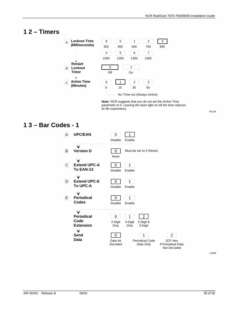
1 2 – Timers
R0136
Lockout Time(Milliseconds)
A
RestartLockoutTimer
B
8
350
0
Off
1
On
Active Time(Minutes)
C 0
0
1
15
2
30
3
60
No Time-out (Always Active)
Note: NCR suggests that you do not set the Active Timeparameter to 0. Leaving the laser light on all the time reducesits life expectancy.
0
450
1
600
2
750
3
900
4
1050
5
1200
6
1350
7
1500
1 3 – Bar Codes - 1 A
Disable0
PeriodicalCodeExtension
SendData
UPC/EAN
Version D
Extend UPC-ATo EAN-13
Extend UPC-ETo UPC-A
PeriodicalCodes
B
C
D
E
Enable1
None0
Disable0
Enable1
Disable0
Enable1
Disable0
Enable1
2-DigitOnly
05-DigitOnly
12-Digit &5-Digit
2
Data AsDecoded
0Periodical Code
Data Only
12CF Hex
If Periodical DataNot Decoded
2
14393
Must be set to 0 (None)

NCR RealScan 7875-7000/8000 Installation Guide
06/03 AIP-00342 Release B 40 of 56
1 4 – Bar Codes - 2 Code 39
Disable
0
MinimumCharactersAllowed
Full ASCII
Check DigitPresent
TransmitCheck Digit
2 - F Default:
Allow One- orTwo-CharacterTags
A
B
C
D
E
F
Enable
1
8
Disable
0
Enable
1
Disable
0
Enable
1
Disable
0
Enable
1
Disable
0
Enable
1
14394

NCR RealScan 7875-7000/8000 Installation Guide
AIP-00342 Release B 06/03 41 of 56
1 5 – Bar Codes - 3 Interleaved2 of 5
Bar CodeLength
Check DigitPresent
TransmitCheck Digit
Value 1 CharactersMinimum
Default:
Value 2 CharactersMaximum
Disable0A
B
C
D
Enable1
RangeCheck
0SpecificCheck
1
Character 10 - 3
Character 20 - 9
0 8
Default:
Character 10 - 3
Character 20 - 9
1 6
Disable0
Enable1
Disable0
Enable1
B049
1 7 – Bar Codes - 4
Minimum DataCharactersAllowed
Code 128
UCC 128
0Disable
A
B
C
1Enable
1 2 3 4 5
0Disable
1Enable
B050

NCR RealScan 7875-7000/8000 Installation Guide
06/03 AIP-00342 Release B 42 of 56
1 8 – Bar Codes - 5
20596
RSS Enable
Scans RequiredOn RSS 14
B
A
Disable
0Enable
RSS 14 Only
1
1 Scan
12 Scans
23 Scans
34 Scans
4
Enable RSS E Only
2Enable
RSS 14 &RSS E
3
Scans RequiredOn RSS E
C
1 Scan
12 Scans
23 Scans
34 Scans
4
UCC-128EmulationMode
D
Normal Mode
0UCC-128
Emulation Mode
1
1 6 – Label Identifiers 0
5
0
R0143
UPC-A
Identifier TypeDefault Prefix
Common Byte 1 Default:
Common Byte 2
Unique Identifier Default: Varies according to Bar Code Type.
Bar Code Type
Common Byte
A
B
C
D
2None
3Unique Prefix
0 - 7Hex Character
0 - FHex Character
Default:
D
4 20 - 7Hex Character
0 - FHex Character
2UPC-E
3EAN-8
4EAN-13
5Code 39
6Code 128
7Interleaved
2 of 5
0None
1Common Byte 1
2Common Byte 2
3Both Common
Bytes
0 - 7Hex Character
0 - FHex Character

NCR RealScan 7875-7000/8000 Installation Guide
AIP-00342 Release B 06/03 43 of 56
2 0 – RS-232 Parameters - 1 0
300
11809
Stop Bits AndCharacterLength
Note: Parity must be Odd or Even on a scale unit. Odd is used ifNone is selected.
Baud Rate
Handshake
Parity
A
B
C
D
1600
21200
32400
44800
59600
619200
0Odd
1Even
4None
01 Stop Bit
7-Bit Character
11 Stop Bit
8-Bit Character
22 Stop Bits
7-Bit Character
32 Stop Bits
8-Bit Character
0RTS Low
CTS Ignored
1RTS High
CTS Ignored
2Raise RTS
Wait for CTS
3Raise RTSIgnore CTS
4RTS Low
Wait for CTS
5RTS High
Wait for CTS
2 1 – RS-232 Parameters - 2 BCC Options
Disable
0 Default: Scanner Only - DisableScanner/Scale - Enable
InterfaceControl
B
Check DigitC
Note: Check Digit parameter also applies to UPC-Ewhen using for OCIA communictions.
11810
AEnable
1
None
0ACK/NAK
1XOn/XOff
2ACK/NAK & XOn/XOff
3
0Disable UPC-ADisable EAN-8Disable EAN-13Disable UPC-E
1 2 3Enable UPC-AEnable EAN-8Enable EAN-13Disable UPC-E
Disable UPC-ADisable EAN-8Disable EAN-13Enable UPC-E
Enable UPC-AEnable EAN-8Enable EAN-13Enable UPC-E

NCR RealScan 7875-7000/8000 Installation Guide
06/03 AIP-00342 Release B 44 of 56
2 2 – RS-232 Prefix Byte Prefix ByteA
ASCII Code
Disable
0
0 - 7 0 Default
Hex Character(ASCII Code Chart)
Enable
1
B 0 - F
Hex Character(ASCII Code Chart)
2
R0035
2 3 – RS-232 Terminator Byte NOTE: A Terminator Byte is required on a
scale unit. If you select Disable, it is ignored and an ETX (03) is sent.
Terminator ByteA
ASCII Code
Disable
0
0 - 7 0 Default
Hex Character(ASCII Code Chart)
Enable
1
B 0 - F
Hex Character(ASCII Code Chart)
3
11811
2 4 – RS-232 Communications Options Message Delay 0
No Delay
Scanner orScanner/ScaleFormat
Normal orEavesdropMode
Good Weigh Tone
110 ms Delay
250 ms Delay
4Scanner Only
5Scanner/Scale
6Normal Mode
7Eavesdrop
Mode
8Disable
9Enable
12163

NCR RealScan 7875-7000/8000 Installation Guide
AIP-00342 Release B 06/03 45 of 56
3 0 – Scale Parameters
Scanner/Scale
Model Number
IBM Address
3
9.995 kg / 13.995 kg
Scanner Only
4
Address 6A
5Address 6B
6Address 6E
7
Toggle Between9.995 kg and
13.995 kg
B
11812
3 2 – Miscellaneous Parameters
IBM Tone Control(Good Read Tone Control)
OCIA Price Display
IBM Rexmit Control
OCIA Blank Display in Price Mode
Enable/Disable Voice Messages
IBM Tag Data Format
5-Second Weight Display TimerDisable
1Enable
2
Disable3
Enable4
Disable5
Enable6
3 Times7
Forever8
Disable9
EnableA
ToggleD Default: Enabled
HexE
ASCIIF
11823
3 6 – Dual Cable Interface Options Scale Type 0
No AdapterExit Parameter
A 1
Avery
2
Weightronix
3
TECParallel
4
CasioParallel
5
Datachecker
6
Toledo
14396

NCR RealScan 7875-7000/8000 Installation Guide
06/03 AIP-00342 Release B 46 of 56
ASCII Code Chart
707172737475767778797A7B7C7D7E7F
pqrstuvwxyz{|}
DEL
606162636465666768696A6B6C6D6E6F
abcdefghijklmno
505152535455565758595A5B5C5D5E5F
PQRSTUVWXYZ[\]^_
404142434445464748494A4B4C4D4E4F
@ABCDEFGHIJKLMNO
303132333435363738393A3B3C3D3E3F
01234
65
789:;<=>?
202122232425262728292A2B2C2D2E2F
SP!"#$%&'()*+,-./
101112131415161718191A1B1C1D1E1F
DLEDC1DC2DC3DC4NAKSYNETBCANEMSUBESCFSGSRSUS
000102030405060708090A0B0C0D0E0F
NULLSOHSTXETXEOTENQACKBELBSHTLFVTFFCRS0S1
ASCII Code Chart
~
R0040

NCR RealScan 7875-7000/8000 Installation Guide
AIP-00342 Release B 06/03 47 of 56
Appendix A – Pan-Oston PO-2 This checkstand has a metal plate on the left side of the scanner area. This plate must be removed and replaced with a plastic plate.
1. Remove the Side Plate by removing four screws. 2. Use two bolts to connect the Cover Rail (NCR Part Number 497-0430977) to the Plastic
Side Plate (NCR Part Number 497-0430978). 3. Attach the new Side Plate assembly to the checkstand using the screws previously removed. 4. Install a Sensormatic Power Pad Label on the Plastic Side Plate. Remove the paper backing
and place the label in the middle of the Plastic Side Plate. 5. Go to Step 2 – Connect the Components.

NCR RealScan 7875-7000/8000 Installation Guide
06/03 AIP-00342 Release B 48 of 56
Appendix B – Pan-Oston PO-2 This checkstand is designed to accommodate a Sensormatic Antenna in the space to the left of the scanner. Since this is not needed, a Sensormatic Filler Plate must be installed.
1. Install the Sensormatic Filler Plate using two screws. 2. Install a Sensormatic Power Pad Label on the Sensormatic Filler Plate. Remove the paper
backing and place the label in the middle of the Filler Plate. 3. Go to Step 2 – Connect the Components

NCR RealScan 7875-7000/8000 Installation Guide
AIP-00342 Release B 06/03 49 of 56
Appendix C – Pan-Oston PO-4 This checkstand has a metal side panel next to the scanner position. A hole must be cut in this panel and covered with a Plastic Side Plate.
1. Use a saw to cut out a portion of the metal side panel that is 13” long and 3 ½ “ deep. This should start 1.15” from the front edge of the side panel.
2. Use two bolts to connect the Cover Rail (NCR Part Number 497-0430977) to the Plastic Side Plate (NCR Part Number 497-0430978).
3. Attach the new Side Plate assembly to the checkstand using four screws. 4. Install a Sensormatic Power Pad Label on the Plastic Side Plate. Remove the paper backing
and place the label in the middle of the Plastic Side Plate. 5. Go to Step 2 – Connect the Components.

NCR RealScan 7875-7000/8000 Installation Guide
06/03 AIP-00342 Release B 50 of 56
Appendix D – Regulatory Information
Federal Communications Commission (FCC) Radio Frequency Interference Statement
Note: This equipment has been tested and found to comply with the limits for a Class A digital device, pursuant to Part 15 of the FCC Rules. These limits are designed to provide reasonable protection against harmful interference when the equipment is operated in a commercial environment. This equipment generates, uses, and can radiate radio frequency energy and, if not installed and used in accordance with the instruction manual, may cause harmful interference to radio communications. Operation of this equipment in a residential area is likely to cause harmful interference in which case the user is required to correct the interference at his own expense.
Information to User: This equipment must be installed and used in strict accordance with the manufacturer’s instructions. However, there is no guarantee that interference to radio communications will not occur in a particular commercial installation. If this equipment does cause interference, which can be determined by turning the equipment off and on, the user is encouraged to consult an NCR service representative immediately.
Caution: NCR is not responsible for any radio or television interference caused by unauthorized modifications of this equipment or the substitution or attachment of connecting cables and equipment other than those specified by NCR. Such unauthorized modifications, substitutions, or attachments may void the user’s authority to operate the equipment. The correction of interferences caused by such unauthorized modifications, substitutions, or attachments are the responsibility of the user.
Voluntary Control Council for Interference (VCCI) Radio Frequency Interference Statement
16105
Canadian Department of Communications Radio Frequency Interference Statement
This digital apparatus does not exceed the Class A limits for radio noise emissions from digital apparatus set out in the Radio Interference Regulations of the Canadian Department of Communication.
Le présent appareil numérique n’émet pas de bruits radioélectriques dépassant les limites applicables aux appareils numériques de la Class A prescrites dans le Règlement sur le brouillage radioélectriques édicté par Ministère des Communications du Canada.

NCR RealScan 7875-7000/8000 Installation Guide
AIP-00342 Release B 06/03 51 of 56
Scale Regulatory Country, state, and local regulatory agency notification of an installation of a weighing instrument or Point of Service terminal’s device is required. Failure to comply with government Weights and Measures regulations can result in criminal prosecution of individuals and can jeopardize the ability to conduct normal business. The NCR 7875 Scanner/Scale has been certified in many countries. Contact the NCR office of Weights & Measures and Laser Safety for specific country approvals.
NCR Office of Weights & Measures and Laser Safety Dennis A. Krueger 2651 Satellite Boulevard Duluth, GA 30096-5810
Phone: 770-623-7743 Fax: 770-623-7827 E-Mail: [email protected]
NCR RealScan 7875-7000/8000 Installation Guide
06/03 AIP-00342 Release B 52 of 56
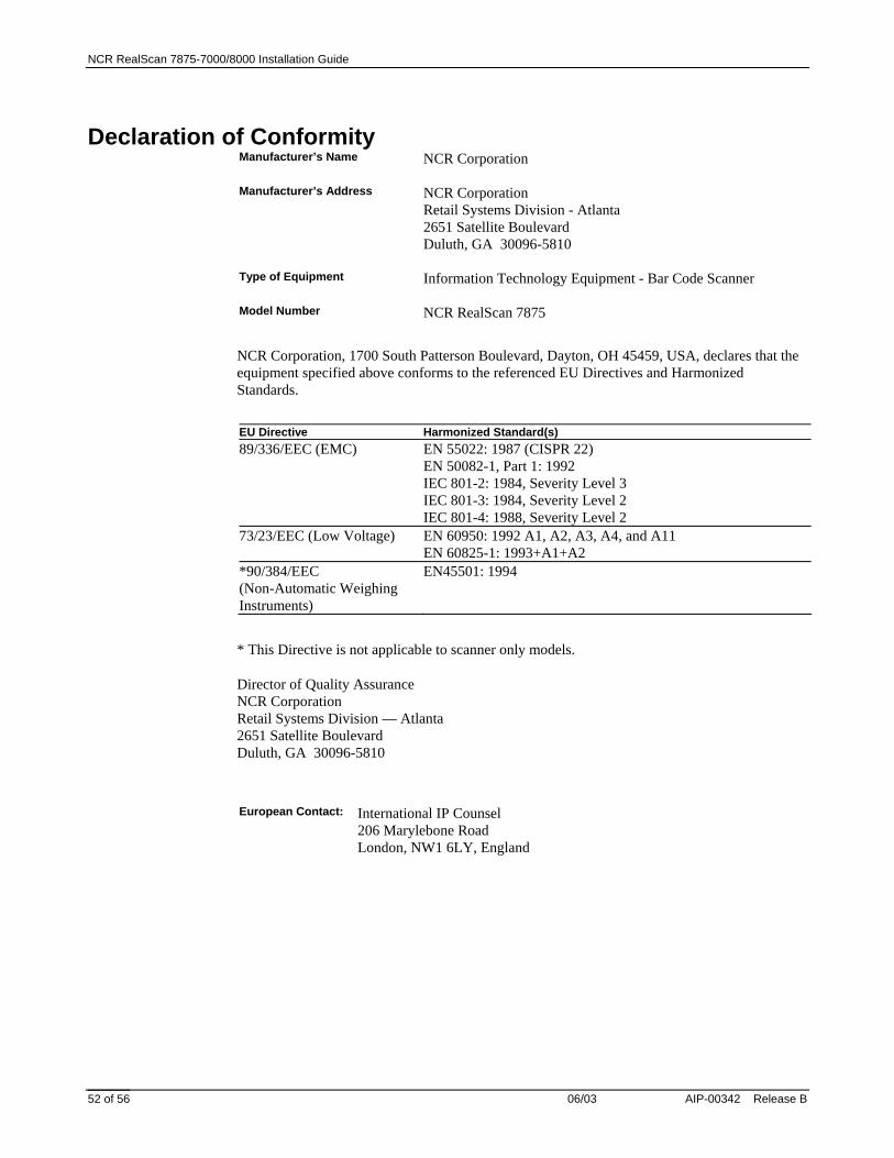
Declaration of Conformity Manufacturer’s Name NCR Corporation Manufacturer’s Address NCR Corporation
Retail Systems Division - Atlanta 2651 Satellite Boulevard Duluth, GA 30096-5810
Type of Equipment Information Technology Equipment - Bar Code Scanner Model Number NCR RealScan 7875
NCR Corporation, 1700 South Patterson Boulevard, Dayton, OH 45459, USA, declares that the equipment specified above conforms to the referenced EU Directives and Harmonized Standards.
EU Directive Harmonized Standard(s) 89/336/EEC (EMC) EN 55022: 1987 (CISPR 22)
EN 50082-1, Part 1: 1992 IEC 801-2: 1984, Severity Level 3 IEC 801-3: 1984, Severity Level 2 IEC 801-4: 1988, Severity Level 2
73/23/EEC (Low Voltage) EN 60950: 1992 A1, A2, A3, A4, and A11 EN 60825-1: 1993+A1+A2
*90/384/EEC (Non-Automatic Weighing Instruments)
EN45501: 1994
* This Directive is not applicable to scanner only models.
Director of Quality Assurance NCR Corporation Retail Systems Division — Atlanta 2651 Satellite Boulevard Duluth, GA 30096-5810
European Contact: International IP Counsel
206 Marylebone Road London, NW1 6LY, England

NCR RealScan 7875-7000/8000 Installation Guide
AIP-00342 Release B 06/03 53 of 56
Laser Safety
Laser Safety and Name Plate Labels The NCR RealScan 7875 Scanner is not intended for long term viewing of the direct laser light. However, the unit is safe if used as it is intended.
16103
Class IIa Laser Product. Avoid Long-term Viewing of direct Laser Light.
Appareil à Laser de classe IIa Eviter Toute ExpositionProlongèe de la vue à la lumiè re laser directe.
Class IIa Producto Laser. Tratè De no ver directamente èl RayoLaser por mucho tiempò. (IEC CLASS 1 LASER PRODUCT)
NCR CORPORATIONDuluth, GA 30096
Date ManufacturedClass 7875Model
SerialTracer
This device complies with Part 15 of the FCC Rules.Operation is subject to the following two conditions:
undesired operation.
(1) This device may not cause harmful interference,and (2) this device must accept any interferencereceived, including interference that may cause
This apparatus does not exceed the Class A limitsfor radio noise emissions set out in the RadioInterference Regulations of Canada.
Le presént appareil n'emet pas de bruits
brouillage radioélectnique du Canada.
radioélectriques dépassant les limites de laClassé A prescrites dans le Reglement sur le
VDC 5 3 A12 2
-12 0.3One or more of the U.S. Patents listed below apply: Patents Pending 5,229,588; 4,868,375; 4,575,623; 4,797,551; 4,851,667; 4,253,018; 4,272,675; 4,282,426; 4,679,154; 5,194,722; 5,276,316; 5,334,825; 5,262,625; 5,256,865; 5,144,114; 5,152,355; 5,065,842; 5,023,818; 4,656,344; 4,715,457; 4,716,281; 4,760,539; 5,459,308; 5,531,293; D368,398; 5,886,336; 6,059,189; 6,082,186; 6,158,660
Complies with 21 CFR 1040.10 and 1040.11except for deviations pursuant to laser notice No 50, July 26, 2001
LISTEDI.T.E.E152553
ACN 000 003 592
VCCI-A
Assembly in Mexico
Laser Module Label
This laser moduledoes not complywith 21CFR1040.USE ONLY AS ACOMPONENT.
14953
NCR RealScan 7875-7000/8000 Installation Guide
06/03 AIP-00342 Release B 54 of 56
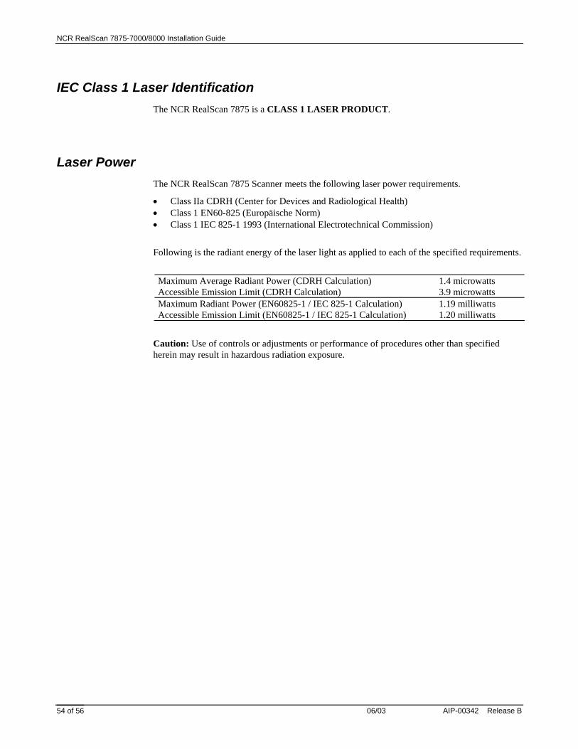
IEC Class 1 Laser Identification The NCR RealScan 7875 is a CLASS 1 LASER PRODUCT.
Laser Power The NCR RealScan 7875 Scanner meets the following laser power requirements.
• Class IIa CDRH (Center for Devices and Radiological Health) • Class 1 EN60-825 (Europäische Norm) • Class 1 IEC 825-1 1993 (International Electrotechnical Commission)
Following is the radiant energy of the laser light as applied to each of the specified requirements.
Maximum Average Radiant Power (CDRH Calculation) 1.4 microwatts Accessible Emission Limit (CDRH Calculation) 3.9 microwatts Maximum Radiant Power (EN60825-1 / IEC 825-1 Calculation) 1.19 milliwatts Accessible Emission Limit (EN60825-1 / IEC 825-1 Calculation) 1.20 milliwatts
Caution: Use of controls or adjustments or performance of procedures other than specified herein may result in hazardous radiation exposure.

NCR RealScan 7875-7000/8000 Installation Guide
AIP-00342 Release B 06/03 55 of 56

NCR RealScan 7875-7000/8000 Installation Guide
06/03 AIP-00342 Release B 56 of 56
Copyright © 2003 by NCR Corporation