realistic modelling of composite and rc floor slabs under - spiral
TRANSCRIPT

1
Realistic Modelling of Composite and R/C Floor Slabs under
Extreme Loading – Part I: Analytical Method
B.A. Izzuddin1, X.Y. Tao
2 and A.Y. Elghazouli
3
ABSTRACT
This paper presents a new flat shell element for composite and reinforced concrete (R/C)
floor slabs subject to extreme loading conditions, accounting for the effects of geometric as
well as material nonlinearities. A novel feature of the proposed element is its treatment of
problems associated with the geometric orthotropy of composite floor slabs, achieved through
a modification of the conventional Reissner-Mindlin hypothesis. The new element is
formulated in a local co-rotational framework, enabling the use of linear strain-displacement
relationships, with the influence of geometric nonlinearity addressed through transformations
between the local and global systems. In addition, a robust nonlinear material model is
proposed for concrete which captures the salient response characteristics under extreme
loading conditions, including the effects of elevated temperature due to fire. The proposed
element is implemented within the nonlinear structural analysis program ADAPTIC, which is
used in this paper to provide several verification examples, focusing principally on the
significance of the assumptions made in the element formulation. Extensive verification
against experiments on composite and R/C floor slabs is undertaken in the companion paper,
where favourable comparisons between the predictions of the proposed method and
experimental results are generally achieved.
CD Database subject headings: Composite structures; Concrete structures; Finite elements;
Fires; Nonlinear analysis; Slabs.
1 Reader in Computational Structural Mechanics, Department of Civil and Environmental Engineering,
Imperial College, London SW7 2AZ, United Kingdom. Member, ASCE.
2 Post-doctoral Research Associate, Department of Civil and Environmental Engineering,
Imperial College, London SW7 2AZ, United Kingdom.
3 Reader in Engineering Structures, Department of Civil and Environmental Engineering,
Imperial College, London SW7 2AZ, United Kingdom. Member, ASCE.
2
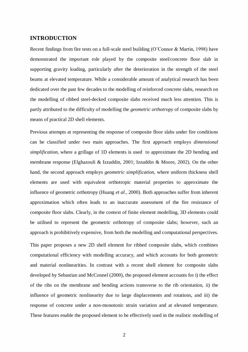
INTRODUCTION
Recent findings from fire tests on a full-scale steel building (O‟Connor & Martin, 1998) have
demonstrated the important role played by the composite steel/concrete floor slab in
supporting gravity loading, particularly after the deterioration in the strength of the steel
beams at elevated temperature. While a considerable amount of analytical research has been
dedicated over the past few decades to the modelling of reinforced concrete slabs, research on
the modelling of ribbed steel-decked composite slabs received much less attention. This is
partly attributed to the difficulty of modelling the geometric orthotropy of composite slabs by
means of practical 2D shell elements.
Previous attempts at representing the response of composite floor slabs under fire conditions
can be classified under two main approaches. The first approach employs dimensional
simplification, where a grillage of 1D elements is used to approximate the 2D bending and
membrane response (Elghazouli & Izzuddin, 2001; Izzuddin & Moore, 2002). On the other
hand, the second approach employs geometric simplification, where uniform thickness shell
elements are used with equivalent orthotropic material properties to approximate the
influence of geometric orthotropy (Huang et al., 2000). Both approaches suffer from inherent
approximation which often leads to an inaccurate assessment of the fire resistance of
composite floor slabs. Clearly, in the context of finite element modelling, 3D elements could
be utilised to represent the geometric orthotropy of composite slabs; however, such an
approach is prohibitively expensive, from both the modelling and computational perspectives.
This paper proposes a new 2D shell element for ribbed composite slabs, which combines
computational efficiency with modelling accuracy, and which accounts for both geometric
and material nonlinearities. In contrast with a recent shell element for composite slabs
developed by Sebastian and McConnel (2000), the proposed element accounts for i) the effect
of the ribs on the membrane and bending actions transverse to the rib orientation, ii) the
influence of geometric nonlinearity due to large displacements and rotations, and iii) the
response of concrete under a non-monotonic strain variation and at elevated temperature.
These features enable the proposed element to be effectively used in the realistic modelling of

3
composite floor slabs under extreme conditions, including those due to fire, blast and
earthquake loading. In addition, the element is equally applicable to the modelling of
reinforced concrete (R/C) slabs, which are clearly a special geometrically isotropic case of
composite slabs.
The paper proceeds with providing the formulation details of the new shell element, where a
modification of the conventional Reissner-Mindlin hypothesis is proposed for dealing with
geometric orthotropy and the material discontinuity between adjacent ribs. In addition, the
element is presented in two hierarchic linear/quadratic forms, enabling the selective
activation/deactivation of the higher-order quadratic approximation. The incorporation of the
proposed element within a recently developed large displacement co-rotational approach
(Izzuddin, 2002) is then discussed, achieved through transformations between the local co-
rotational and the global reference systems. Subsequently, a robust material model is
proposed for the nonlinear response of concrete, which accounts for the effects of tensile
cracking and softening, crack closure, compressive nonlinearity and elevated temperature.
The new shell element has been implemented within the nonlinear structural analysis
program ADAPTIC (Izzuddin, 1991), which is used in this paper to provide basic verification
of the element for uniform-thickness and ribbed plates in the elastic small and large
displacement ranges. The companion paper (Elghazouli & Izzuddin, 2004) provides further
extensive verification of the proposed nonlinear analysis method, focussing on the influence
of geometric and material nonlinearities for both ambient and elevated temperature
conditions. In addition, it discusses practical aspects of the response of R/C and composite
floor slabs subject to extreme loading, including the effects of compressive and tensile
membrane action.
COMPOSITE SLAB FORMULATION
As illustrated in Fig. 1, a steel-decked composite floor slab is characterised by geometric
orthotropy, a feature which renders its modelling by means of conventional shell elements
unrealistic. The proposed shell element addresses this issue in the context of small-strain
large-displacement analysis, where the following assumptions are made:

4
1. The rib geometry is perfectly trapezoidal, but with an arbitrary aspect ratio
2. The concrete cover depth and the steel deck thickness are uniform
3. Steel reinforcement belonging to a particular layer and acting along a specific
direction lies at a constant distance from the concrete surface, and is smeared as an
equivalent uniform thickness plate acting uniaxially, several reinforcement layers
with different orientations being allowed
4. Perfect bond exists between concrete and both the steel reinforcement and deck
5. Direct out-of plane stresses in the concrete are negligible
6. Out-of-plane transverse shear stresses in the concrete rib are negligible
7. The inclined webs of the steel deck sustain only uniaxial stresses in the longitudinal
direction
The formulation of the new element in a local reference system is presented hereafter,
considering i) the proposed kinematic description, ii) discretisation using local element
freedoms, and iii) determination of the local element forces and tangent stiffness. The global
element response, including the treatment of geometric nonlinearity using a co-rotational
approach, is discussed in a later section.
Kinematics
The conventional Reissner-Mindlin hypothesis (Zienkiewicz & Taylor, 1991) is based on the
assumption that any through-thickness straight line initially normal to the slab surface
remains straight after deflection. Clearly, applying this hypothesis to ribbed composite-floor
slabs is unrealistic, since it can lead to considerable transverse direct stresses in the ribs when
the slab is subjected to transverse planar stretching or bending, stresses which cannot be
sustained in the real slab due to material discontinuity between two adjacent ribs (Fig. 1).
Accordingly, the Reissner-Mindlin hypothesis is modified in this work, effectively through
an enriched approximation for the rib displacement field beyond the requirements of the
conventional hypothesis.

5
In discretising the composite floor slabs into shell elements, four variants of a generic flat
shell elements are employed, as illustrated in Fig. 2. The proposed kinematic description,
representing the modified Reissner-Mindlin hypothesis, is formulated with reference to a
local coordinates system, the origin located at the geometric centre of the cover region, as
depicted in Fig. 3. In addition, natural coordinates ),( , shown in Fig. 4, are employed for
planar reference so as to facilitate discretisation. Hereafter, the proposed kinematic
description is discussed for the cover and rib regions, considering the different requirements
of the four element variants.
Cover region
The conventional Reissner-Mindlin hypothesis is retained in the cover region for all four
element variants, where the displacements )w,v,u( of a material point located at )z,,( are
related to the reference planar displacements )w,v,u( ppp and rotations of the normal
),( yx by:
0
),(
),(
z
),(w
),(v
),(u
)z,,(w
)z,,(v
)z,,(u
y
x
p
p
p
(1)
with, referring to Figs. 3 and 4,
2
tz
2
t
2
Ly:11
2
Wx:11
(2)
The strain components considered for the concrete in the cover region are:

6
y
w
z
vx
w
z
u
x
v
y
u
y
vx
u
yz
xz
xy
y
x
(3)
Considering (1) and (2), the concrete strains are therefore related to the natural derivatives of
the planar displacement and rotation fields by:
0
0
W
2
L
2
L
2
W
2
z
w
L
2
w
W
2
v
W
2u
L
2
v
L
2
u
W
2
yx
y
x
p
y
p
x
pp
p
p
yz
xz
xy
y
x
(4)
With the assumption of perfect bond between steel and concrete, the uniaxial strain within
reinforcement, acting at a distance )dz( s from the reference plane and making an angle
)( x with the local x-axis, is obtained as the component of the planar strains of (4) using:
)2sin()2cos(1)2cos(12
1xxyxyxxs (5)
In addition to strains in the concrete and reinforcement, element variant (II) requires the
strains in the steel deck located at )2tz( , which are obtained directly from (4) as the
planar components ),,( xyyx .

7
Rib region
The rib region is considered only for element variants (I), (III) and (IV), where the
conventional Reissner-Mindlin hypothesis is modified through the incorporation of two
additional displacement fields )v,u( rr :
0
)z,,(v
)z,,(u
0
),(
),(
z
),(w
),(v
),(u
)z,,(w
)z,,(v
)z,,(u
r
r
y
x
p
p
p
(6)
The mapping between the real and natural coordinates accounts for the trapezoidal rib shape
(Fig. 2), and is accordingly specific to each of the three element variants:
02
tzh
2
Ly:11
h
)r1(
2
tz
2
Wx:11 r
(7)
with,
(IV)variant :1r
(III)variant :0
(I)variant :r1
r
r
r
(8)
where r is the trapezoidal rib ratio (Fig. 3).
The additional displacement fields )v,u( rr are introduced primarily to improve the
approximation of the planar direct strain )( x and shear strain )( xy within the rib.
Accordingly, the two additional displacement fields correspond to stretching and shear
modes, as demonstrated for element variant (III) in Fig. 5. More generally, the following
characteristics are proposed for the additional displacement fields, depending on the element
variant:

8
)IV(Variant0)z,,1(v)z,,1(u
)III(Variant
)z,,(v)z,,(v
)z,,(u)z,,(u
0)z,,0(v)z,,0(u
)I(Variant0)z,,1(v)z,,1(u
rr
rr
rr
rr
rr
(9)
The above modes correspond to zero additional displacements )v,u( rr along the vertical line
of symmetry bisecting the rib, represented by values of 1,0,1 for variants (I), (III) and
(IV), respectively. Accordingly, deformations along the bisecting vertical lines are assumed
to comply with the Reissner-Mindlin hypothesis, but elsewhere within the rib this hypothesis
is clearly enhanced with stretching and shear modes, the discretisation of which is discussed
later.
Considering (3) and (6–9), the strain components ),,,,( yzxzxyyx are given by:
y
r
xr
y
z
x
y
x
z
prp
rr
y
p
z
rp
rr
x
rp
z
rp
rp
rp
z
yz
xz
xy
y
x
W
2
L
2
L
2
W
2
z
w
L
2vv
z
v
w
W
2uu
z
u
vv
W
2uu
L
2
vv
L
2
uu
W
2
(10)
where,
h
)r1(
2
tz1WWz (11)
and,

9
)r1(2
tzh
)r1(rr
(12)
Although a compatible formulation is achieved with the above strains in (10), a better
response prediction is achieved if xz is neglected in the rib, as demonstrated in the
“Verification” section. This default assumption is considered to be realistic, since the
corresponding shear stress could not be sustained at significant levels in the rib region due to
material discontinuity between adjacent ribs.
Again, with the assumption of perfect bond between the steel and concrete, the strains in the
horizontal part of the deck located at )2thz( are obtained directly from (10) as the
planar components ),,( xyyx . For the inclined parts of the deck, on the other hand, only
the longitudinal strain component ( y ) is considered, as obtained directly from (10), the
stress components corresponding to the two remaining direct and shear strains assumed to be
relatively small.
Discretisation
The kinematic description proposed in the previous subsection is expressed in terms of
relationships between the various material strains on the one hand and the planar
displacements )w,v,u( ppp , the rotations of the normal ),( yx and the additional rib
displacements )v,u( rr on the other. These fields are discretised in terms of basic and
hierarchic element freedoms using polynomial shape functions as follows:
4 4L Q
p i i i i
i 1 i 1
u ( , ) ( , ) ( , )
N u N u (13.a)
4 4L Q
p i i i i
i 1 i 1
v ( , ) ( , ) ( , )
N v N v (13.b)
4 4 4L Q C
p i i i i i i
i 1 i 1 i 1
w ( , ) ( , ) ( , ) ( , )
N w N w N w (13.c)
4 4L Q
x i xi i xi
i 1 i 1
( , ) ( , ) ( , )
N N (13.d)

10
4 4L Q
y i yi i yi
i 1 i 1
( , ) ( , ) ( , )
N N (13.e)
2 3L Q
r i ri i ri
i 1 i 1
u ( , , z) ( , , z) ( , , z)
R u R u (13.f)
2 3L Q
r i ri i ri
i 1 i 1
v ( , , z) ( , , z) ( , , z)
R v R v (13.g)
where, as illustrated in Fig. 6,
]4,1i[yixiiii ),,,,( wvu are the basic translational and rotational local nodal
freedoms associated with bilinear shape functions )( LiN
]4,1i[yixiiii ),,,,( wvu are hierarchic translational and rotational side freedoms
associated with quadratic shape functions )( QiN
]4,1i[i )( w are hierarchic out-of-plane translational freedoms associated with cubic
shape functions )( CiN
]2,1i[riri ),( vu are rib freedoms along the two edges (1–2) and (3–4) associated with
linear approximation functions )( LiR
]2,1i[riri ),( vu are hierarchic rib freedoms along the two edges (1–2) and (3–4)
associated with quadratic approximation functions )( QiR
]3i[riri ),( vu are element-specific hierarchic rib freedoms associated with a quadratic
approximation function )( Q3R
and where all the shape functions are detailed in Appendix A.
One of the benefits of utilising hierarchic freedoms is that the element can be readily
employed in its basic linear form excluding the “[…]” terms of (13), or in its higher-order
quadratic form including these terms. An additional important benefit of hierarchic freedoms
is that the element may be used in either of its two forms within the same co-rotational large
displacement approach, as discussed in the next section. It should also be noted that the
approximation for the out-of-plane displacements )w( p is always one order higher than that

11
for the rotations of the normal ),( yx , a feature which reduces inaccuracies associated with
the phenomenon of shear locking (Hughes & Tezduyar, 1981).
Element Response
For a given set of values for the element freedoms, the relevant strains in the concrete, the
steel reinforcement and the steel deck can be evaluated according to the kinematic
assumptions and the approximated displacement fields discussed in the two previous
subsections. This evaluation is undertaken over the element domain at several Gauss points
employed in the numerical integration of the element response. Corresponding to each set of
material strains at a given Gauss point, the material stresses can be established taking into
account the effects of material nonlinearity, as discussed in a later section. The element
resistance forces are then obtained as the weighted aggregate of the material stresses using
the principle of virtual work.
The following expressions demonstrate the contributions from various materials to the
element resistance vector (f), with subscripts c, d and s denoting the concrete, deck and
reinforcement, respectively:
)IV(&)III(),I(Variants
)II(Variant
s
s
ncovs
ribd
ribc
covc
ncovs
covd
covc
fffff
ffff
(14.a)
where,
)IV(Variant
)III(Variant
)I(Variant
ribmid,d
ribleft,d
ribd
ribright,d
ribmid,d
ribleft,d
ribd
ribright,d
ribmid,d
ribd
fff
ffff
fff
(14.b)
In the above expressions, sn refers to the total number of reinforcement layers, each layer
being associated with a unique combination of distance from the reference plane )dz( s
and orientation )( x , while subscripts left, mid and right refer to the three parts of the deck
attached to the rib.

12
The contributions of the different materials to f are evaluated using the principle of virtual
work, where the stresses at every Gauss point for a given material are weighted by a B matrix
which relates the corresponding strain components at the Gauss point to the element
freedoms. With the terms of the various B matrices readily available from the expressions in
two previous subsections, the contributions to f are given by:
xyzgn
1i i
T
cyzxzxyyxTc
xyzi
covc w
8
tLWBf (15.a)
xygn
1i i
T
dxyyxTd
xyi
dcovd w
4
tLWBf (15.b)
xygn
1iis
Ts
xyi
scovs w
4
tLWBf (15.c)
xyzgn
1i i
T
cyzxzxyyxTc
xyzi
zribc w
2
W
4
hLBf (15.d)
xygn
1i i
T
dxyyxTd
xyi
dribmid,d w
4
tLrWBf (15.e)
)1at(00w
8
tLW)r1(h4yzgn
1i i
T
dyTd
yzi
d2
r2
ribleft,d
Bf (15.f)
)1at(00w
8
tLW)r1(h4yzgn
1i i
T
dyTd
yzi
d2
r2
ribright,d
Bf (15.g)
where,
)w,w,w(xyzi
yzi
xyi are Gauss weighting factors associated with integration
point (i) and used for 2D (x–y, y–z) and 3D (x–y–z) integration, respectively,
with )n,n,n( xyzg
yzg
xyg representing the corresponding number of Gauss points
),,,,,( yzxzxysyx are the material stresses corresponding to the strain
components ),,,,,( yzxzxysyx , respectively

13
)t,t( sd represent the thickness of the deck and the smeared reinforcement
layer, respectively
)W,( zr are rib properties given by (8) and (11), respectively
with the remaining geometric parameters as depicted in Fig. 3.
In addition to the element resistance vector (f), an element tangent stiffness matrix (k) is
required for guiding the incremental iterative solution of the nonlinear equations of
equilibrium (Crisfield, 1991). This can be assembled from the various material contributions
in a similar way to f, where an example contribution from the concrete in the cover region is
given by:
xyzgn
1iictc
Tc
xyzi
covc w
8
tLWBDBk (16)
in which tcD represents the tangent modulus matrix of concrete.
It is worth noting that k accounts for material nonlinearity, which is discussed in more detail
later, with local geometric nonlinearity excluded as a result of the linear kinematic
relationship between material strains and the local displacement fields. It is important to
emphasise, however, that local geometric nonlinearity becomes negligible in relation to
global geometric nonlinearity when an element is used to represent small regions of the slab
domain, as is the intention of the present work. The following section discusses the
incorporation of the proposed shell element within a recently developed co-rotational
approach for the global geometrically nonlinear analysis of floor slabs.
GEOMETRIC NONLINEARITY
The proposed slab element is formulated in a local reference system where the corresponding
local deformations are assumed to be sufficiently small to justify linear strain-displacement
relationships. In the context of geometrically nonlinear analysis, this assumption becomes
exponentially accurate as the finite element mesh is refined, provided the local reference
system follows the deformed element configuration and excludes rigid body modes, in which
case it is referred to as a local co-rotational system (Crisfield, 1997; Belytschko et al., 2000).

14
With such an approach, geometric nonlinearities in the local system may be ignored, but the
effect of rigid body modes are accounted for by means of geometrically nonlinear
transformations between the local and global reference systems.
Despite the diversity of approaches for geometrically nonlinear analysis, the co-rotational
approach offers exceptional benefits for structural problems with rotational degrees of
freedom, particularly when accounting for arbitrarily large rigid body rotations. Moreover,
this approach can be developed and implemented quite independently of the specific element
formulation, and can therefore act as a „harness‟ around different geometrically linear
elements (Crisfield, 1997), rendering them immediately applicable to the modelling of
geometric nonlinearities.
The proposed slab element is incorporated within a recently developed co-rotational approach
(Izzuddin, 2002), which offers several significant improvements over previous co-rotational
approaches (Crisfield, 1997), including i) the choice of global rotational freedoms, ii) the
definition of the local co-rotational reference system and iii) the determination of local
freedoms. Not only do these improvements lead to a much simpler, yet powerful, new co-
rotational method, but they additionally realise several important benefits including complete
insensitivity to the size of the load step as well as symmetry of the tangent stiffness matrix.
With reference to Fig. 7, the adopted co-rotational approach (Izzuddin, 2002) is developed for
4-noded quadrilateral elements, where five global degrees of freedoms ),( ii nd are employed
for each node (i), id representing the three global translations and in representing the two
smallest components of the initial normal to the element plane. With the local co-rotational
x–y axes defined as the bisectors of the element diagonals in the deformed configuration
(Fig. 7), the values of the local nodal freedoms ),,,,( yixiiii wvu can be readily determined
in terms of the global nodal freedoms (Izzuddin, 2002). Through the principle of virtual
work, the element forces and tangent stiffness in the global system can then be obtained as
transformations of the corresponding local element entities using first and second partial
derivatives of the local with respect to global freedoms (Izzuddin, 2002).

15
Although in its basic form the adopted co-rotational approach is applicable to 4-noded
quadrilateral elements, its extension to higher-order quadrilateral elements is in fact straight
forward when the additional freedoms are hierarchic relative to the local element deformed
configuration (Izzuddin, 2002), as is the case with the proposed slab element. Such hierarchic
freedoms are then directly shared between adjacent elements, depending on side connectivity,
and are treated along with the global nodal freedoms as the primary unknowns sought by the
nonlinear solution procedure.
MATERIAL NONLINEARITY
The proposed slab element benefits from a wide range of nonlinear material models
previously developed for steel under ambient (Izzuddin, 1991; Izzuddin & Lloyd Smith,
1996) and elevated temperatures (Song et al., 2000), as well as under high strain-rates
(Izzuddin & Fang, 1997). Such models can be readily employed to represent the stress-strain
response of the reinforcement and the deck, as required by the local element formulation,
under a variety of normal/extreme static/dynamic conditions, including those due to fire,
explosion and earthquake loading.
In view of the above, detailed consideration is given here only to the modelling of concrete,
where the following features are sought in an appropriate nonlinear material model:
Simplicity and numerical robustness without compromising the main response
characteristics of concrete
Representation of tensile cracking and compressive nonlinearity, including
softening effects
Modelling of crack opening and closure, the latter being an important
requirement under dynamic loading and fire conditions
Consideration of the effects of elevated temperature, both in terms of the
resulting thermal strains and the change of material properties
A new material model is proposed for concrete which fulfils the above objectives, where
nonlinearity is considered for the biaxial planar stresses, with the out-of-plane shear response
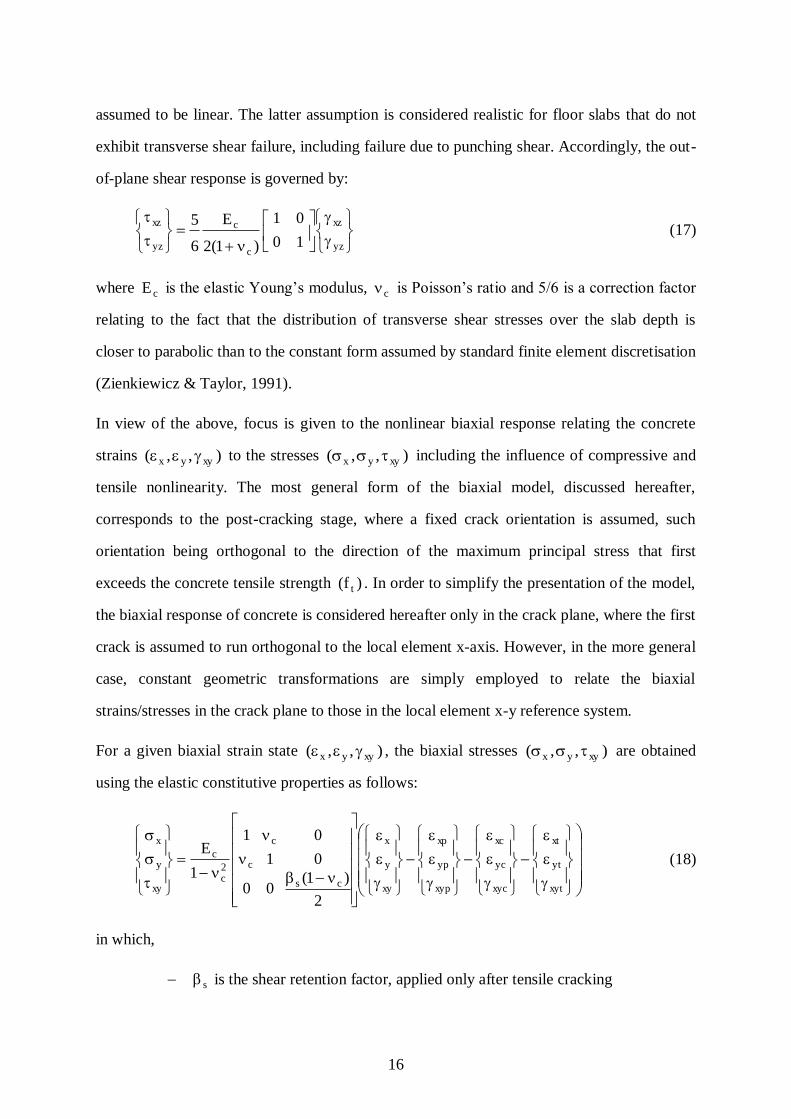
16
assumed to be linear. The latter assumption is considered realistic for floor slabs that do not
exhibit transverse shear failure, including failure due to punching shear. Accordingly, the out-
of-plane shear response is governed by:
yz
xz
c
c
yz
xz
10
01
)1(2
E
6
5 (17)
where cE is the elastic Young‟s modulus, c is Poisson‟s ratio and 5/6 is a correction factor
relating to the fact that the distribution of transverse shear stresses over the slab depth is
closer to parabolic than to the constant form assumed by standard finite element discretisation
(Zienkiewicz & Taylor, 1991).
In view of the above, focus is given to the nonlinear biaxial response relating the concrete
strains ),,( xyyx to the stresses ),,( xyyx including the influence of compressive and
tensile nonlinearity. The most general form of the biaxial model, discussed hereafter,
corresponds to the post-cracking stage, where a fixed crack orientation is assumed, such
orientation being orthogonal to the direction of the maximum principal stress that first
exceeds the concrete tensile strength )f( t . In order to simplify the presentation of the model,
the biaxial response of concrete is considered hereafter only in the crack plane, where the first
crack is assumed to run orthogonal to the local element x-axis. However, in the more general
case, constant geometric transformations are simply employed to relate the biaxial
strains/stresses in the crack plane to those in the local element x-y reference system.
For a given biaxial strain state ),,( xyyx , the biaxial stresses ),,( xyyx are obtained
using the elastic constitutive properties as follows:
xyt
yt
xt
xyc
yc
xc
xyp
yp
xp
xy
y
x
cs
c
c
2c
c
xy
y
x
2
)1(00
01
01
1
E (18)
in which,
s is the shear retention factor, applied only after tensile cracking

17
),,( xypypxp are the plastic strains due to compressive nonlinearity
),,( xycycxc are the strains due to tensile cracking
),,( xytytxt are the thermal strains, related only to the material temperature,
where )( ytxt and )0( xyt for an isotropic material
The following subsections discuss in detail the treatment of compressive nonlinearity and
tensile cracking in the biaxial x-y plane.
Compressive Nonlinearity
Compressive nonlinearity in the biaxial response of concrete is accounted for using principles
of plasticity, where an evolving plastic interaction surface is employed (Fig. 8), as defined by
the constraint:
c1c2c21
cxy,yx IJ)b2(I
3
b12),(
C (19.a)
with,
yx1I (19.b)
2xy
2yyx
2x2 )(
3
1J (19.c)
In (19.a), c is the current compressive strength of concrete, and )6.0b( c is a compressive
interaction parameter which provides a best fit against experimental results (e.g. Kotsovos &
Pavlovic, 1995). It should be noted that the interaction curve proposed in (19), although
expressed in terms of stress invariants 1I and 2J , represents accurately the interaction of
biaxial stresses but is in fact inappropriate for triaxial compressive interaction, the latter being
outside the scope of the proposed material model.
The evolution of the plastic interaction surface is determined by the variation of the
compressive strength ( c ) with the cumulative equivalent plastic strain ( p ), where
compressive hardening and softening (Fig. 8) are experienced for ( cp ) and ( cp ),
respectively, according to the following parametric expression:

18
c2
c
p
c
c
c
p
c
c
c
p
cc
c f
r1
s11
r1
r2)s1(s
(20)
with,
c
cc
E
f (21)
In the above, cs and cr are non-dimensional material parameters used to reflect the start of
compressive nonlinearity and the residual post-crushing strength (Fig. 8).
Should the compressive constraint of (19.a) be exceeded, additional plastic strains are
introduced according to the associated flow rule:
xyc
xcyc
ycxc
c
oxyp
oyp
oxp
xy
y
x
oxyp
oyp
oxp
xyp
yp
xp
)b2(4
b24
b24
2
C
C
C
(22)
where, ),,( oxyp
oyp
oxp are the plastic strains at the start of the equilibrium step, and is a
positive scalar used to satisfy the interaction equation in (19.a). It is noted that the stresses
),,( xyyx and strength )( c in (22) are the current unknown entities, and hence the
correction to the interaction curve is based on the single-step backward Euler method
(Crisfield, 1991), which has the benefit of leading to a symmetric consistent tangent modulus
matrix (Izzuddin & Lloyd Smith, 1996).
Finally, the equivalent cumulative plastic strain ( p ), required for the evaluation of c in
(20), is based on the equivalence of incremental plastic work:
oxypxyp
oypyp
oxpxp
T
xy
y
x
oppc )( (23)

19
which in conjunction with (19) and (22) leads to:
c
1opp
2
I1 (24)
where, op is the equivalent cumulative plastic strain at the start of the equilibrium step, and
1I is the first stress invariant defined in (19.b). It is worth noting that p and c are
interdependent according to (20) and (24), and hence an iterative procedure is required on the
material level to determine these entities. However, this does not unduly complicate the
model application, since iterations are in any case required by the backward Euler correction
procedure and additionally for satisfying any simultaneous tensile cracking constraints, as
discussed in the following subsection.
Tensile Cracking
The tensile response of concrete is modelled by means of separate strength envelopes for the
biaxial stresses ),,( xyyx , as depicted in Figs. 9 and 10. Considering first the direct
stresses ),( yx , the envelope constraints can be expressed, depending on the respective
crack strains ),( ycxc , as follows:
0withotherwise
0for0
for0
xcxtx
xcx
oxcxcxtx
(25.a)
0withotherwise
0for0
for0
ycyty
ycy
oycycyty
(25.b)
where ),( oyc
oxc are the maximum crack strains accumulated up to the start of the current
equilibrium step.
The current tensile strengths, required in (25), are obtained from the nominal tensile strength
)f( t of the undamaged concrete, but accounting for the post-cracking softening effect:
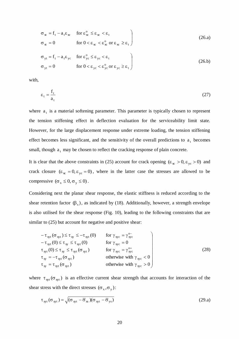
20
txcoxcxcxt
txcoxcxcttxt
or0for0
foraf (26.a)
tycoycycyt
tycoycycttyt
or0for0
foraf (26.b)
with,
t
tt
a
f (27)
where ta is a material softening parameter. This parameter is typically chosen to represent
the tension stiffening effect in deflection evaluation for the serviceability limit state.
However, for the large displacement response under extreme loading, the tension stiffening
effect becomes less significant, and the sensitivity of the overall predictions to ta becomes
small, though ta may be chosen to reflect the cracking response of plain concrete.
It is clear that the above constraints in (25) account for crack opening )0,0( ycxc and
crack closure )0,0( ycxc , where in the latter case the stresses are allowed to be
compressive )0,0( yx .
Considering next the planar shear response, the elastic stiffness is reduced according to the
shear retention factor )( s , as indicated by (18). Additionally, however, a strength envelope
is also utilised for the shear response (Fig. 10), leading to the following constraints that are
similar to (25) but account for negative and positive shear:
0withotherwise)(
0withotherwise)(
for)()0(
0for)0()0(
for)0()(
xycxytxytxy
xycxytxytxy
oxycxycxytxytxyxyt
xycxytxyxyt
oxycxycxytxyxytxyt
(28)
where )( xytxyt is an effective current shear strength that accounts for interaction of the
shear stress with the direct stresses ),( yx :
))(()( ysxytxsxytxytxyt (29.a)
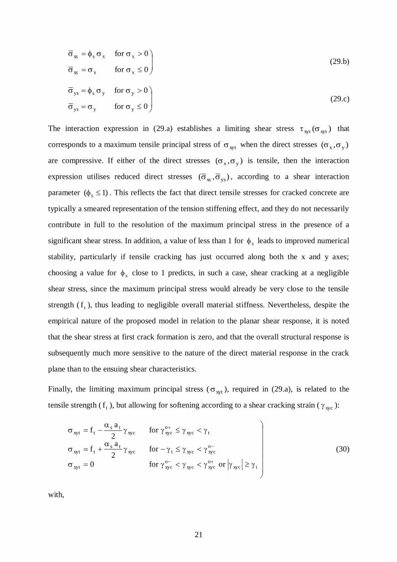
21
0for
0for
xxxs
xxsxs (29.b)
0for
0for
yyys
yysys
(29.c)
The interaction expression in (29.a) establishes a limiting shear stress )( xytxyt that
corresponds to a maximum tensile principal stress of xyt when the direct stresses ),( yx
are compressive. If either of the direct stresses ),( yx is tensile, then the interaction
expression utilises reduced direct stresses ),( ysxs , according to a shear interaction
parameter )1( s . This reflects the fact that direct tensile stresses for cracked concrete are
typically a smeared representation of the tension stiffening effect, and they do not necessarily
contribute in full to the resolution of the maximum principal stress in the presence of a
significant shear stress. In addition, a value of less than 1 for s leads to improved numerical
stability, particularly if tensile cracking has just occurred along both the x and y axes;
choosing a value for s close to 1 predicts, in such a case, shear cracking at a negligible
shear stress, since the maximum principal stress would already be very close to the tensile
strength ( tf ), thus leading to negligible overall material stiffness. Nevertheless, despite the
empirical nature of the proposed model in relation to the planar shear response, it is noted
that the shear stress at first crack formation is zero, and that the overall structural response is
subsequently much more sensitive to the nature of the direct material response in the crack
plane than to the ensuing shear characteristics.
Finally, the limiting maximum principal stress ( xyt ), required in (29.a), is related to the
tensile strength ( tf ), but allowing for softening according to a shear cracking strain ( xyc ):
txycoxycxyc
oxycxyt
oxycxyctxyc
tstxyt
txycoxycxyc
tstxyt
orfor0
for2
af
for2
af
(30)
with,

22
ts
tt
a
f2
(31)
where s is a parameter expressing the shear softening relative to direct tensile softening.
Considering (30) and Fig. 10, it is clear that two failure envelopes are effectively employed
for negative and positive shear, thus allowing, for example, considerable resistance to be
maintained for negative shear even after considerable cracking and loss of resistance has
occurred for positive shear.
Model Solution Procedure
An iterative solution procedure is typically required on the material level to determine the
biaxial concrete stresses ),,( xyyx corresponding to strains ),,( xyyx . If on the basis
of the elastic response in (18) any of the compressive or tensile constraints, (19), (25) or (28),
are exceeded, the plastic strains ),,( xypypxp and/or the cracking strains ),,( xycycxc are
modified, from their values at the start of the equilibrium step, in order to ensure that the
corresponding constraints are satisfied. A sophisticated procedure has been developed for this
purpose by the authors (Izzuddin & Elghazouli, 2003), which also enables the numerical
evaluation of the consistent tangent modulus matrix ( tcD ) without the need for a complex
analytical formulation.
After structural equilibrium is achieved, the plastic strains ),,( oxyp
oyp
oxp are updated to their
current respective values ),,( xypypxp . However, the maximum crack strains are updated
only if they are exceeded by their current respective values, that is:
xycoxycxyc
oxyc
xycoxycxyc
oxyc
ycoycyc
oyc
xcoxcxc
oxc
if
if
if
if
(32)
In addition, at the start of each equilibrium step, the effect of elevated temperature on the
thermal strains ),,( xytytxt , required in (18), and on the concrete material properties is
established. In the present model, the concrete elastic modulus )E( c , Poisson‟s ratio )( c ,
compressive strength )f( c , tensile strength )f( t , tensile softening parameter )a( t , and

23
thermal strain )( ytxt , are all assumed to vary with temperature according to different
trilinear curves.
Finally, it is again noted that the biaxial model details are presented above with reference to a
fixed crack plane, where it is assumed that the first crack runs orthogonal to the x axis.
Nevertheless, in the general case where the crack plane is not identical to the local element
x-y reference system, constant geometric transformations are employed to relate the strains,
stresses and tangent modulus matrix in the two reference planes.
VERIFICATION
The proposed 2D shell element for flat R/C and composite slabs has been implemented
within the nonlinear structural analysis program ADAPTIC (Izzuddin, 1991) v2.9.15. Two
verification examples are provided hereafter using ADAPTIC, focusing on the modelling
accuracy for uniform-thickness and ribbed plates, with specific reference to the elastic
response. Detailed verification of the formulation against experiments on R/C and composite
floor slabs, including the influence of steel and concrete material nonlinearity, is undertaken
in the companion paper (Elghazouli & Izzuddin, 2003).
Uniform-Thickness Plate
An elastic simply supported square plate, having a uniform thickness of 70 mm and an area
of 6×6 m2, is subjected to a uniformly distributed loading, as depicted in Fig. 11(a). The plate
is modelled with the proposed 2D shell formulation, using the basic linear as well as the
hierarchic quadratic forms, where three alternative meshes consisting of 6×6, 10×10 and
20×20 elements are employed in each case. For verification purposes, the plate is also
modelled using a conventional 20-noded quadratic 3D brick formulation already incorporated
within ADAPTIC (Izzuddin, 1991), where a mesh of 20×20×2 elements is utilised.
Considering a small out-of-plane load of 1 kN/m2, the predictions of the transverse
displacement at the centre of the plate, as obtained from the various element meshes, are
provided in Table 1. These results demonstrate the accuracy of the proposed 2D shell
formulation with reference to the prediction of the 3D brick formulation, where favourable

24
agreement is observed for the fine meshes of the 2D and 3D elements. As expected, the
quadratic form of the proposed shell formulation converges at a coarser mesh than required
by the linear form, although a good approximation is obtained by the linear form with a mesh
of 10×10 elements. Accordingly, the hierarchic quadratic freedoms are most beneficial for
coarse meshes, and they may be ignored as the mesh is sufficiently refined. Interestingly, the
prediction of the 2D quadratic shell formulation with a mesh of 20×20 elements is slightly
more flexible than that of the 3D brick formulation with a mesh of 20×20×2 element, which
is attributed to the different approximations presented by the two models of the out-of-plane
shear strains.
Ribbed Plate
A geometrically orthotropic ribbed plate is considered here, with the cross-section depicted in
Fig. 11(b), and with the remaining geometric and material properties identical to the previous
example. In order to establish the relative accuracy of the 2D shell element and the
significance of its underlying assumptions, three types of analysis are considered hereafter.
Central rib subject to basic deformation modes
One element type (III), representing a central rib of the considered plate with a length of
200mm, is subjected to the six basic deformation modes that induce planar stresses, as
indicated in Table 2. Four modelling cases (A to D) are considered, representing
combinations of i) whether a conforming or zero xz shear strain is assumed in the rib, and ii)
whether additional rib freedoms that represent the modified Reissner-Mindlin hypothesis are
employed. For comparison purposes, two alternative meshes (2×1×4 and 4×1×8) of 3D brick
elements are employed to model the same central rib, where the finest discretisation is over
the depth and the coarsest is in the longitudinal direction.
The results from the 2D shell element, considering both the linear and quadratic forms, and
from the 3D brick element are presented in Table 2, where the predicted strain energy is
normalised relative to that of a uniform thickness plate for which the rib region is ignored.
With the linear and quadratic shell elements providing identical results for cases (A) and (D),

25
it is clear that ignoring the rib freedoms over-estimates the normalised strain energy, or
relative response stiffness, by over 60% for three of the six modes. Overall, the most efficient
and effective representation of the six modes is achieved with the linear form of the shell
element based on case (B), for which additional rib freedoms are employed but the rib shear
strain xz is ignored. With this model, however, significant inaccuracy arises for the bending
mode in the transverse x direction, where the stiffness is underestimated by around 38%, and
for the twisting mode, where the stiffness is overestimated by around 20%. Interestingly, for
the bending mode, the underestimate is due to ignoring xz in the rib, where the true solution
is between the results of (B) and (C). Despite this shortcoming, the inaccuracies obtained
with the proposed ribbed element based on case (B) are only a fraction of those resulting
from a uniform thickness element that ignores the rib region, which underestimates the
stiffness for the two aforementioned modes by 63% and 82%, respectively. Furthermore,
these two modes do not feature strongly in the response of ribbed slabs subject to typical
boundary conditions, and hence the influence of any associated inaccuracy on the overall
response is small, as shown in the next subsection. Considering the remaining four modes,
which are more dominant in the large displacement analysis of realistic ribbed slabs, the
inaccuracy of the proposed element based is limited to a maximum of 7%, whereas the
uniform thickness element underestimates the response stiffness by as much as 88%.
Linear analysis of plate
The ribbed plate is considered here under a small out of-plane load of 1 kN/m2, where simply
supported conditions are assumed. Due to the ribbed configuration, the mesh utilising the
proposed 2D shell element is chosen to consist of 41 and 20 element divisions in the
transverse and longitudinal directions, respectively, leading to 20 elements type (I), 400
elements type (II), 380 elements type (III) and 20 elements type (IV), as depicted in
Fig. 12(a). For verification purposes, a mesh of 60×20 3D brick elements is employed, where
2 and 4 element layers are used in the cover and ribbed regions, respectively, as shown in
Fig. 12(b).

26
Comparison of the predictions of the proposed 2D shell element for the previously described
modelling cases (A to D) against the result from the fine mesh of 3D brick elements is
provided in Table 3. Considering first the predictions of the linear shell element, it is clear
that the most accurate prediction is based on case (B), where the rib freedoms are included
with xz ignored. This also shows that amongst the three cases, cases (A) and (D) are the
least accurate with an error of over 12 %, emphasising the significance of the proposed
modification of the Reissner-Mindlin hypothesis. Such an error becomes even larger as the
rib depth increases and/or as the plate attracts more of the load through bending in the
direction transverse to the ribs. Considering next the predictions of the quadratic shell
element, it is clear that any improvement over the linear form is rather marginal. This
highlights the adequacy of the linear form in the modelling of ribbed slabs, which typically
impose a fine mesh of elements due to geometric considerations. Interestingly, and as
observed for the uniform thickness plate, the prediction of the mesh of quadratic elements is
marginally more flexible than that of the 3D brick element, which is again attributed to the
different approximations presented by the two models of the out-of-plane shear strains. In
view of these findings, the linear form of the proposed 2D shell element based on case (B) is
used as the preferred modelling tool for ribbed composite floor slabs, and therefore forms the
basis of further verification and application studies undertaken in the companion paper
(Elghazouli & Izzuddin, 2003).
Large Displacement analysis of plate
Finally, the accuracy of the proposed 2D shell element in the large displacement range,
allowing for tensile membrane effects, is demonstrated by considering the elastic response
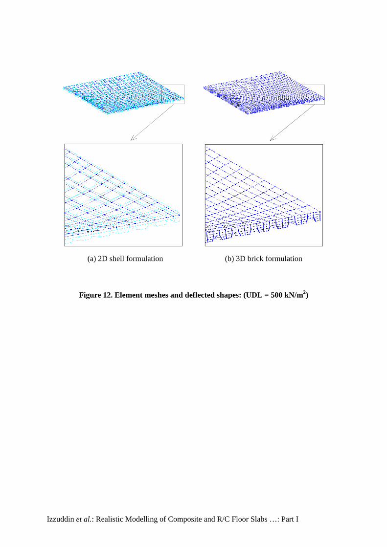
under a large out-of-plane load of 500 kN/m2. The deflected shapes obtained from the linear
form of the 2D shell element, based on case (B), and from the 3D brick element are depicted
in Fig. 12, where very good agreement is observed. Inspecting further the load deflection
response in Fig. 13, an excellent match is observed between the predictions of the proposed
shell element including rib freedoms, that is case (B), and the detailed 3D brick model.
27
Again, the importance of the additional rib freedoms is highlighted, where significant errors
are shown to arise in the large displacement range if these freedoms are suppressed.
With the accuracy of the proposed shell element verified against the most realistic model for
geometrically orthotropic plates based on a 3D brick element, its computational superiority
over such a model is clearly evident. Considering the large displacement analysis, the
analysis employing the 3D brick element consumed around 22hrs of CPU time on a 1 GHz
Pentium III PC, whereas the same analysis based on the proposed shell element required just
over 2mins of CPU time, thus representing a computational saving of over 99.8 %!
CONCLUSION
This paper presents a new method for the nonlinear analysis of R/C and composite floor
slabs, accounting for geometric and material nonlinearity. In particular, the proposed method
deals with the geometric orthotropy of steel-decked composite slabs, which hitherto could
only be modelled using computationally demanding 3D elements, by means of an efficient
new shell element which is also applicable to R/C slabs as a special case.
The proposed shell element is formulated in a local reference system, where the conventional
Reissner-Mindlin hypothesis is modified to reflect the discontinuity in the material between
the ribs of a composite floor slab. This is achieved through the introduction of additional rib
freedoms, which are associated with hierarchic displacement fields specific to the ribs. In
addition, the element is presented in two hierarchic linear/quadratic forms, enabling the
selective activation/deactivation of the higher-order quadratic approximation. Full details of
the element formulation are presented, including the displacement and strain approximations
in the cover and rib regions for the concrete, steel reinforcement and steel decking.
The incorporation of the proposed element within a recently developed large displacement
co-rotational approach is then discussed, where the previously formulated local element
response is transformed to a global reference system common to all elements representing the
structure. Furthermore, a robust material model is proposed for the nonlinear response of

28
concrete, accounting for the effects of tensile cracking and softening, crack closure,
compressive nonlinearity and elevated temperature.
The new shell element has been implemented within ADAPTIC, which is used in this paper
to provide basic verification of the element for uniform-thickness and ribbed plates in the
elastic small and large displacement ranges. Comparisons against detailed 3D models
demonstrate excellent agreement for the uniform thickness plate, where very good
approximation is obtained with the linear form of the shell element using a relatively coarse
mesh of 10×10 elements. For the ribbed plate, investigations carried out on an isolated central
rib subject to basic deformation modes highlight the significance of additional rib freedoms
and, hence, the proposed modification of the Reissner-Mindlin hypothesis, where for three of
the six modes considered ignoring the rib freedoms can lead to more than 60% stiffer
response. The most efficient and effective approximation is achieved with the linear form of
the shell element utilising additional rib freedoms and ignoring the rib transverse shear strain,
where it is shown that the most significant deformation modes are modelled with very good
accuracy. For such modes, the inaccuracy of the proposed 2D shell element is limited to a
maximum of 7%, whereas that of a uniform thickness shell element based on the cover depth
can be as much as 88%. The least accurately represented mode by the proposed shell element
is the transverse bending mode, where the response stiffness can be underestimated by 38%,
though a uniform thickness element can underestimate the stiffness of the same mode by
63%. Notwithstanding this inaccuracy, when considering the overall response of a ribbed
plate, the proposed 2D shell element provides excellent agreement to within 1%, both for the
small and large displacement ranges. Significantly, the comparisons also highlight the
computational superiority of the proposed 2D shell modelling over 3D modelling, where
computational savings in excess of 99.8 % are achieved.
The companion paper provides further extensive verification of the proposed nonlinear
analysis method, focussing on the influence of geometric and material nonlinearities, where
favourable comparisons are made against a number of experiments under ambient and
elevated temperature conditions. In addition, it discusses practical aspects of the response of

29
R/C and composite floor slabs subject to extreme loading, including the effects of
compressive and tensile membrane action.
ACKNOWLEDGEMENT
The authors gratefully acknowledge the financial support provided for this work by the UK
EPSRC under grant GR/L96523.
30
REFERENCES
[1] Belytschko, T., Liu, W.K., and Moran, B. (2000), Nonlinear Finite Elements for
Continua and Structures, Wiley, Chichester, England.
[2] Crisfield, M.A. (1991), Non-linear Finite Element Analysis of Solids and Structures,
Vol. 1, Wiley, Chichester, UK.
[3] Crisfield, M.A. (1997), Non-linear Finite Element Analysis of Solids and Structures,
Vol. 2, Wiley, Chichester, UK.
[4] Elghazouli, A.Y., and Izzuddin, B.A. (2001), “Analytical Assessment of the Structural
Performance of Composite Floors Subject to Compartment Fires”, Fire Safety Journal,
36, 769-793.
[5] Elghazouli, A.Y., and Izzuddin, B.A. (2004), “Realistic Modelling of Composite and
R/C Floor Slabs under Extreme Loading – Part II: Verification and Application”,
Companion Paper.
[6] Huang, Z., Burgess, I.W., and Plank, R.J. (2000), “Effective Stiffness Modelling of
Composite Concrete Slabs in Fire”, Engineering Structures, 22, 1133-1144.
[7] Hughes, T.J.R., and Tezduyar, T.E. (1981), “Finite Elements Based upon Mindlin Plate
Theory with Particular Reference to the Four-Node Bilinear Isoparametric Element”,
Journal of Applied Mechanics, 48, 587-596.
[8] Izzuddin, B.A. (1991), Nonlinear Dynamic Analysis of Framed Structures, PhD Thesis,
Imperial College, University of London.
[9] Izzuddin, B.A. (2002), “Advanced Large Displacement Analysis of Composite Floor
Slabs”, Proc. 15th
ASCE Engineering Mechanics Conference, New York.
[10] Izzuddin, B.A., and Elghazouli, A.Y. (2003), “An Advanced Concrete Model for R/C
and Composite Floor Slabs Subject to Extreme Loading”, Proc. 9th
International
Conference on Civil and Structural Engineering Computing, The Netherlands.

31
[11] Izzuddin, B.A., and Fang, Q. (1997), “Rate-Sensitive Analysis of Framed Structures -
Part I: Model Formulation and Verification”, Structural Engineering and Mechanics,
5(3), 221-237.
[12] Izzuddin, B.A., and Lloyd Smith, D. (1996), “Large Displacement Analysis of Elasto-
Plastic Thin-Walled Frames - Part I: Formulation and Implementation”, Journal of
Structural Engineering, ASCE, 122(8), 905-914.
[13] Izzuddin, B.A., and Moore, D.B. (2002), “Lessons from a Full-Scale Fire Test”,
Structures and Buildings, Proc. Institution of Civil Engineers, 152(4), 319-329.
[14] Kotsovos, M.D. and Pavlovic, M.N. (1995), Structural Concrete: Finite Element
Analysis for Limit-State Design, Thomas Telford Publication Ltd., England, UK.
[15] O‟Connor, M.A., and Martin, D.M. (1998), “Behaviour of a Multi-Storey Steel Framed
Building Subjected to Fire Attack”, Journal of Constructional Steel Research, 46(1–3),
Paper No. 169.
[16] Sebastian, W.M., and McConnel, R.E. (2000), “Nonlinear FE Analysis of Steel-
Concrete Composite Structures”, Journal of Structural Engineering, ASCE, 126(6),
662-674.
[17] Song, L., Izzuddin, B.A., Elnashai, A.S., and Dowling, P.J. (2000), “An Integrated
Adaptive Environment for Fire and Explosion Analysis of Steel Frames - Part I:
Analytical Models”, Journal of Constructional Steel Research, 53(1), 63-85.
[18] Zienkiewicz, O.C., and Taylor, R.L. (1991), The Finite Element Method: Vol. 2 – Solid
and Fluid Mechanics, Dynamics and Nonlinearity, McGraw Hill.

32
TABLES
2D shell 3D brick
Type Linear Quadratic -
Mesh 6×6 10×10 20×20 6×6 10×10 20×20 20×20×2
Displacement (mm) 7.49 8.62 8.82 8.79 8.85 8.87 8.83
Table 1. Central transverse displacement of uniform-thickness plate
2D shell 3D brick
Type Linear Quadratic
Mesh:
2×1×4
Mesh:
4×1×8
Case (A) (B) (C) (D) (B) (C)
xzrib No No Yes Yes No Yes
rib freedoms No Yes Yes No Yes Yes
Extension (x) 2.00 1.23 1.38 2.02 1.10 1.34 1.29 1.25
Extension (y) 1.74 1.72 1.73 1.74 1.71 1.72 1.72 1.72
Shear (xy) 1.88 1.58 1.58 1.88 1.53 1.53 1.50 1.47
Bending (x) 12.64 1.69 4.42 12.68 1.30 4.09 3.06 2.72
Bending (y) 8.81 8.53 8.65 8.81 8.50 8.63 8.58 8.57
Twisting (xy) 10.78 6.74 6.78 10.83 6.46 6.51 5.78 5.58
Table 2. Normalised strain energy of one central rib for various deformation modes
2D shell 3D brick
Type Linear Quadratic
Mesh:
60×20×(2:4)
Case (A) (B) (C) (D) (B) (C)
xzrib No No Yes Yes No Yes
rib freedoms No Yes Yes No Yes Yes
Displacement (mm) 2.68 3.05 2.82 2.65 3.15 2.87 3.04
Table 3. Central transverse displacement of ribbed plate

33
APPENDIX A: SHAPE FUNCTIONS
The linear, quadratic and cubic shape functions are given by the following respective
expressions:
)1)(1(
)1)(1(
)1)(1(
)1)(1(
4
1),(L
N (33)
)1)(1(
)1)(1(
)1)(1(
)1)(1(
2
1),(
2
2
2
2
QN (34)
)1()1(
)1)(1(
)1()1(
)1)(1(
2
1),(
2
2
2
2
CN (35)
The linear and quadratic approximation functions, utilised for the additional rib displacement
fields, depend on the element variant (Figure 2), and are respectively given by:
)1)(()1(
)1)()(1(
8
1)z,,(L
R Variant (I) (36.a)
)1)((
)1)((
4
1)z,,(L
R Variant (III) (36.b)
)1)(()1(
)1)()(1(
8
1)z,,(L
R Variant (IV) (36.c)
)1)()(1(
)1)(()1(
)1)()(1(
4
1)z,,(
2
2
2
QR Variant (I) (37.a)
)1)((
)1)((
)1)((
2
1)z,,(
2
2
2
QR Variant (III) (37.b)
34
)1)()(1(
)1)(()1(
)1)()(1(
2
1)z,,(
2
2
2
QR Variant (IV) (37.c)
where,
h
tz21
(38)

35
LIST OF FIGURES
Figure 1. Geometric configuration of composite floor slab
Figure 2. Variants of composite shell element
Figure 3. Geometric configuration and local reference system
Figure 4. Local reference systems: real and natural coordinates
Figure 5. Modified Reissner-Mindlin hypothesis: additional rib deformations
Figure 6. Local freedoms of slab element
Figure 7. Global nodal freedoms and local co-rotational system (Izzuddin, 2002)
Figure 8. Plasticity-based compressive response of concrete
Figure 9. Tensile envelopes for direct stresses
Figure 10. Tensile envelope for shear stress
Figure 11. Ribbed plate configuration
Figure 12. Element meshes and deflected shapes: (UDL = 500 kN/m2):
(a) 2D shell formulation, (b) 3D brick formulation
Figure 13. Large displacement response of ribbed slab

Izzuddin et al.: Realistic Modelling of Composite and R/C Floor Slabs …: Part I
Transverse
Longit
udina
l
Out
-of-
plan
e
Concrete
Steel deck
Steel reinforcement
Rib
Cover
Figure 1. Geometric configuration of composite floor slab

Izzuddin et al.: Realistic Modelling of Composite and R/C Floor Slabs …: Part I
(I) (II) (III) (IV)
Figure 2. Variants of composite shell element

Izzuddin et al.: Realistic Modelling of Composite and R/C Floor Slabs …: Part I
L
t
h
r W
W
2
34
1
x,u
y,vz,w
Figure 3. Geometric configuration and local reference system

Izzuddin et al.: Realistic Modelling of Composite and R/C Floor Slabs …: Part I
������������������������������������������������������������������������������������������������������������������������������������������������������������������������������������������������������������������������������������������������������������������������������������������������������������������������������������������������������������������������������������������������������������������������������������������������������������������������������������������������������������������������������������������������������������������������������������������������������������������������������������������������������������������������������������������������������������������������������������������������������������������������������������������������������������������������������������������
2
34
1
x
yz
Real coordinates Natural coordinates
������������������������������������������������������������������������������������������������������������������������������������������������������������������������������������������������������������������������������������������������������������������������������������������������������������������������������������������������������������������������������������������������������������������������������������������������������������������������������������������������������������������������������������������������������������������������������������������������������������������������������������������������������������������������������������������������������������������������������������������������������������������������������������������������������������������������������������������
2
34
1
ξ
ηz
Figure 4. Local reference systems: real and natural coordinates

Izzuddin et al.: Realistic Modelling of Composite and R/C Floor Slabs …: Part I
z
ru,ξ
rv,η
1 2
34
z
ru,ξ
rv,η
1 2
34
Transverse deformations Longitudinal deformations
Figure 5. Modified Reissner-Mindlin hypothesis: additional rib deformations

Izzuddin et al.: Realistic Modelling of Composite and R/C Floor Slabs …: Part I
1y1x111 ,,,, θθθθθθθθwvu 2y2x222 ,,,, θθθθθθθθwvu
3y3x333 ,,,, θθθθθθθθwvu4y4x444 ,,,, θθθθθθθθwvu
1 2
34
2y2x222
2
,,,, θθθθθθθθwvu
w
4y4x444
4
,,,, θθθθθθθθwvu
w
3r3r , vu ξ
η
1r1r
1y1x111
1r1r1
,
,,,,
,,
vu
wvuvuw
θθθθθθθθ
2r2r
3y3x333
2r2r3
,
,,,,
,,
vu
wvuvuw
θθθθθθθθ
Figure 6. Local freedoms of slab element

Izzuddin et al.: Realistic Modelling of Composite and R/C Floor Slabs …: Part I
X,U
Y,V
oxc
oyc
ozc
o13v
o1313vα
o24v
o2424vα
1
2 3
4
Initial configuration
Z,W
3
24v
13v
xc
yc
zc
x
y
z
1
2
4
1d
1nCurrent configuration
Figure 7. Global nodal freedoms and local co-rotational system (Izzuddin, 2002)

Izzuddin et al.: Realistic Modelling of Composite and R/C Floor Slabs …: Part I
cσ
cf
cc fs
cc fr
pεcε
1σ
2σ
cσ−
cσ−
cσ=C
Figure 8. Plasticity-based compressive response of concrete

Izzuddin et al.: Realistic Modelling of Composite and R/C Floor Slabs …: Part I
tf ta
xcεoxcε
xtσ
tε
tf ta
ycεoycε
ytσ
tε
Figure 9. Tensile envelopes for direct stresses

Izzuddin et al.: Realistic Modelling of Composite and R/C Floor Slabs …: Part I
tf
tγ− tγ xycγ−γoxyc
+γoxyc
xytσ
2
atsα2
atsα
Figure 10. Tensile envelope for shear stress

Izzuddin et al.: Realistic Modelling of Composite and R/C Floor Slabs …: Part I
60mm200mm
144.6mm70mm
(b) Ribbed plate cross-section
(a) Uniform-thickness plate
2.0
mm/N1020E 23
=ν×=
6 m
6 m
70 mm
Uniformly distributedloading = 1 kPa
Figure 11. Ribbed plate configuration
Izzuddin et al.: Realistic Modelling of Composite and R/C Floor Slabs …: Part I
(a) 2D shell formulation (b) 3D brick formulation
Figure 12. Element meshes and deflected shapes: (UDL = 500 kN/m2)

Izzuddin et al.: Realistic Modelling of Composite and R/C Floor Slabs …: Part I
0
100
200
300
400
500
600
0 100 200 300 400 500
Displacement (mm)
Loa
d (k
Pa)
2D shell (with rib freedoms)
2D shell (without rib freedoms)
3D brick
Figure 13. Large displacement response of ribbed slab