real-time implementation of a non-invasive tongue-based
TRANSCRIPT

Real-time Implementation of a Non-invasive Tongue-basedHuman-Robot Interface
Michael Mace, Khondaker Abdullah-Al-Mamun, Ravi Vaidyanathan, Shouyan Wang and Lalit Gupta
Abstract— Real-time implementation of an assistive human-machine interface system based around tongue-movement earpressure (TMEP) signals is presented, alongside results froma series of simulated control tasks. The implementation ofthis system into an online setting involves short-term energycalculation, detection, segmentation and subsequent signalclassification, all of which had to be reformulated based onprevious off-line testing. This has included the formulationof a new classification and feature extraction method. Thisscheme utilises the discrete cosine transform to extract the fre-quency features from the time domain information, a univariateGaussian maximum likelihood classifier and a two phase cross-validation procedure for feature selection and extraction. Theperformance of this classifier is presented alongside a real-timeimplementation of the decision fusion classification algorithm,with each achieving 96.28% and 93.12% respectively. Thesystem testing takes into consideration potential segmentationof false positive signals. A simulation mapping commands to aplanar wheelchair demonstrates the capacity of the system forassistive robotic control. These are the first real-time resultspublished for a tongue-based human-machine interface thatdoes not require a transducer to be placed within the vicinityof the oral cavity.
Index Terms— Tongue-movement ear pressure signals, real-timeclassification, assistive HMI.
I. INTRODUCTION
This paper builds on previous work by introducing initialreal-time results for a tongue-movement based communica-tion concept to generate, detect and classify signals online[1], [2]. The output of this classification process can thenbe used for control of peripheral assistive devices, aiding inthe independence of the user. Hands-free communication andcontrol of assistive devices is essential if an individual whohas limited upper body mobility is to be more autonomousand therefore less reliant on carer’s, family and society.Beneficiaries of said devices include but are not limitedto, individuals suffering from spinal cord injury, amputa-tion/disarticulation, stroke, congenital limb deformities and
This research was supported by the UK Engineering and PhysicalSciences Research Council (EPSRC), grant EP/F01869X
Michael Mace is with the Department of Mechanical Engineering,Faculty of Engineering, University of Bristol, UK, BS8 1TR (email:[email protected])
Khondaker Abdullah-Al-Mamun and Shouyan Wang are with the Instituteof Sound and Vibration Research (ISVR), University of Southampton, UK,SO17 1BJ (email: [kam1e08,sy.wang]@soton.ac.uk)
Ravi Vaidyanathan Bristol Robotics Laboratory, Department of Me-chanical Engineering, University of Bristol, Bristol, BS8 1TR, UK andthe US Naval Postgraduate School, Monterey, CA, USA, 93943 (email:r.vaidyanathan]@bristol.ac.uk)
Lalit Gupta is with Department of Electrical and Computer Engineering,Southern Illinois University, IL, USA, 62901 (email: [email protected])
arthritis. The prevalence of these afflictions has been welldocumented in previous papers [1], [2], as well as across theassistive technology literature.
The user expresses their intention by impulsive actions ofthe tongue, creating acoustic signals within the ear canal.These signals have been coined as tongue-movement earpressure (TMEP) signals, due to the nature of their genera-tion and evolution within the oral and auditory regions. Thetongue has been chosen to express the user’s intention dueto it rarely being affected by said afflictions, with it alsoallowing for a multitude of distinct actions to be chosenwhen devising the task specific instruction set. It is alsoknown that the tongue has rich sensory and motor cortexrepresentation that rivals that of fine finger control [3]. Theactions themselves involve placement of the tip of the tongueat the base of the central incisor, left or right first molar andflicking the tongue up (up/backward, left or right action)and placing the tip of the tongue against the palate andflicking down (down/forward action). The right action isshown pictorial in Fig. 1b and the associated waveformconsisting of one second of data sampled at 8 kHz is shownin Fig. 1a.
0 0.1 0.2 0.3 0.4 0.5 0.6 0.7 0.8 0.9 1
−0.5
−0.4
−0.3
−0.2
−0.1
0
0.1
0.2
0.3
0.4
0.5
Time (s)
Am
plit
ud
e (V
)
(a) (b)
Fig. 1. (a) Waveform corresponding to right action (1 sec of data sampledat 8 kHz). (b) Pictorial representation of the right action during execution(arrow shows trajectory of tongue tip).
Using the tongue as command input is not a new concept,with the large number of tongue-based assistive HMI’stestament to its functionality. An overview of the existingassistive HMI technologies which use both the tongue andalternative input methods are presented in [2]. The fun-damental difference of this unique system to others beingthe manner in which these tongue actions are executed andmonitored. Although the execution of these tongue actionsfeel natural they are not normal movements, allowing themto be differentiated from potentially interfering signals thatoccur in everyday life. These interfering signals can becategorized into internal artifacts such as speech, swallowingand coughing and also external noise such as conversation
The 2010 IEEE/RSJ International Conference on Intelligent Robots and Systems October 18-22, 2010, Taipei, Taiwan
978-1-4244-6676-4/10/$25.00 ©2010 IEEE 5486

and road noise. Initial off-line results which consider theseoptions are presented in [4], [5]. The benefits of this systeminclude the lack of intrusion whilst donning the earpiece,simplicity in terms of execution of the natural instructionset, cost, portability, hygienic to use and unobtrusive to don.
An overview of the real-time system is presented interms of its instrumentation and acquisition, preprocessing(filtering, detection and segmentation) required and featureextraction and classification methods. Two classificationstrategies are outlined and empirical results are presentedand compared for both. The system is then shown appliedin simulation to real-time control of a wheelchair movingthrough a constrained 2D environment with conclusionsdrawn in Section V.
II. SYSTEM OVERVIEW
A. Instrumentation and acquisition
The hardware is centered around a small microphonepositioned comfortably within the outer ear canal (externalacoustic meatus) by an associated earpiece housing. Thishousing can either be of generic stock utilising a replaceablefoam tip as seen in Fig. 2 or custom moulded from a siliconimpression of the user’s ear canal, with the moulded hollowacrylic housing commissioned from a hearing aid manufac-turer [6]. This work focuses on the generic earpiece whichis advantageous in terms of cost and time of manufacturewith the trade-off being decreased passive noise rejectionand microphone localization which is important due to thesensitive nature of the signals. Fig. 2 shows the genericearpiece both out of the ear and inserted into the ear of anindividual.
Fig. 2. Generic earpiece - showing it both out of the ear (left) and insertedinto the ear canal (right)
The hardware as a whole consists of the microphonetransducer converting TMEP signal to electrical signal, ananalogue-to-digital (AD) card converting this electrical sig-nal to a digital signal and the processor which turns thisdiscretized signal into a digital output (due to the signalprocessing and classification stages). This hardware can berepresented as an open loop block diagram shown in Fig. 3.
TMEPSignal
Sensor(Microphone)
Interface(AD Card)
Processor(CPU) Classification
Fig. 3. Block diagram showing the system’s required hardware.
TABLE ICONDITIONS FOR DETECTING A TMEP SIGNAL
Condition ReasonEp,q > TL The energy must exceed and recede a lower threshold
to inhibit segmentation of lower energy signalsEp,q < TU The energy can’t exceed an upper threshold to inhibit
high energy signals such as coughingq− p > DL The time to exceed and recede this lower threshold
must be greater then a lower detection durationwindow to inhibit impulsive signals
q− p < DU The time to exceed and recede this lower thresholdmust be less then an upper detection duration win-dow to inhibit longer signals such as swallowing
B. Preprocessing: filtering, detection and segmentation
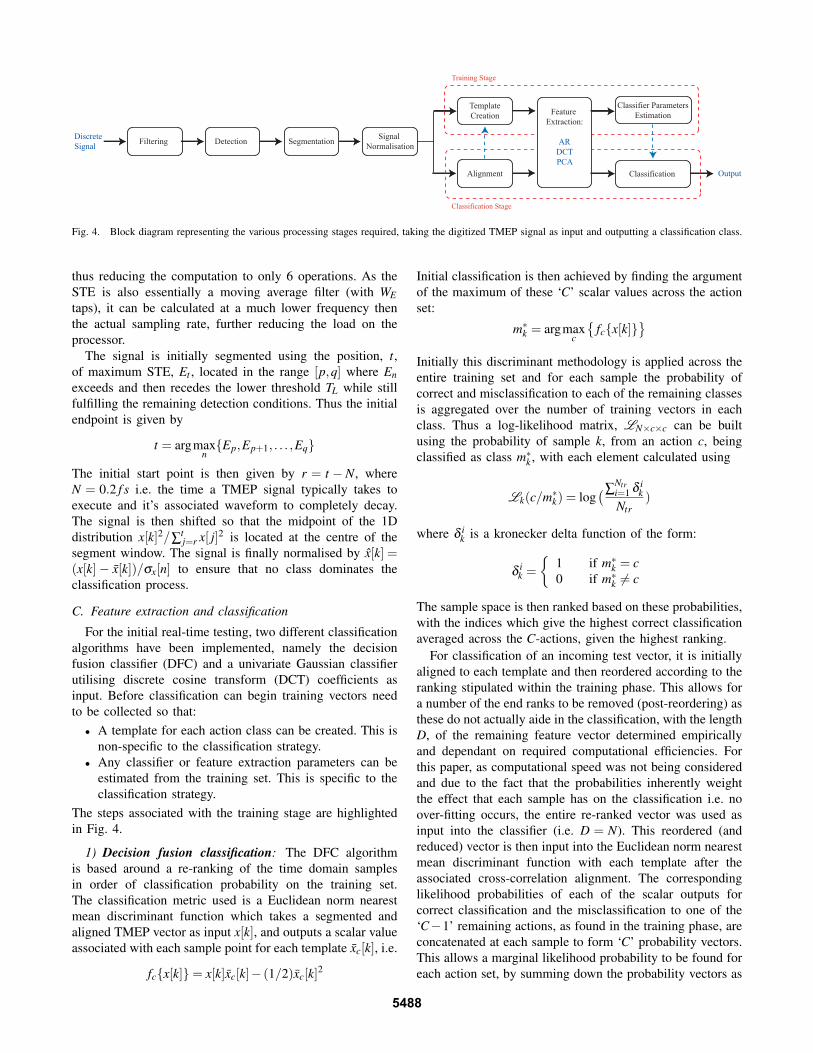
The main stages for processing and classifying the in-coming digital TMEP signal and outputting a classificationclass are shown in Fig. 4. This representation not onlyapplies to this specific system but is a generalisation to anycommunication/classification system which takes an arbitraryanalogue signal as input and requires classification to 1 of‘C’ classes. The filtering block is optional and can simplybe an anti-alias analogue filter realised in the hardware.
Before classification can proceed the continuous streamof digital data has to be monitored so that when a TMEPaction occurs it can be detected and the signal segmentedappropriately. The segmentation process involves creating adata segment of finite dimension that can then be processed.The detection phase is based on similar methods used inautomatic speech recognition (ASR) systems and uses theshort-term energy (STE) of the incoming signal [7]. The STEcan be calculated causally from:
En =n
∑k=n−WE+1
(x[k])2
where x[k] is the incoming digital stream, En is the STE attime index n and WE is the finite window length that the STEis calculated in.
Due to this causality in the calculation, it is required that acircular buffer is implemented so that historical time domaindata can be saved for the required computation, analysis andvisualisation. The STE is continually monitored and whencertain criteria outlined in Table. I are fulfilled, a TMEPsignal is detected.
The segmentation process also requires the use of theSTE, allowing very fast computation during the detectionand segmentation phases (as the STE only requires 2WE −1operations). This is especially beneficial as the STE cal-culation and detection checking is occurring continuallyand thus faster computation will avoid any latency issues.To segment a signal, historical STE data is required andtherefore not only is a circular buffer required for the timedomain information but also for the STE data. This secondbuffer reduces computation further as a new STE value canbe updated using:
En+1 = En + x[n+1]2− x[n−WE ]2
5487
DiscreteSignal Filtering Segmentation Signal
NormalisationDetection
Output
TemplateCreation
Classification
Feature Extraction:
ARDCTPCA
Classifier ParametersEstimation
Training Stage
Classification Stage
Alignment
Fig. 4. Block diagram representing the various processing stages required, taking the digitized TMEP signal as input and outputting a classification class.
thus reducing the computation to only 6 operations. As theSTE is also essentially a moving average filter (with WEtaps), it can be calculated at a much lower frequency thenthe actual sampling rate, further reducing the load on theprocessor.
The signal is initially segmented using the position, t,of maximum STE, Et , located in the range [p,q] where Enexceeds and then recedes the lower threshold TL while stillfulfilling the remaining detection conditions. Thus the initialendpoint is given by
t = argmaxn{Ep,Ep+1, . . . ,Eq}
The initial start point is then given by r = t −N, whereN = 0.2 f s i.e. the time a TMEP signal typically takes toexecute and it’s associated waveform to completely decay.The signal is then shifted so that the midpoint of the 1Ddistribution x[k]2/∑
tj=r x[ j]2 is located at the centre of the
segment window. The signal is finally normalised by x̂[k] =(x[k]− x̄[k])/σx[n] to ensure that no class dominates theclassification process.
C. Feature extraction and classification
For the initial real-time testing, two different classificationalgorithms have been implemented, namely the decisionfusion classifier (DFC) and a univariate Gaussian classifierutilising discrete cosine transform (DCT) coefficients asinput. Before classification can begin training vectors needto be collected so that:• A template for each action class can be created. This is
non-specific to the classification strategy.• Any classifier or feature extraction parameters can be
estimated from the training set. This is specific to theclassification strategy.
The steps associated with the training stage are highlightedin Fig. 4.
1) Decision fusion classification: The DFC algorithmis based around a re-ranking of the time domain samplesin order of classification probability on the training set.The classification metric used is a Euclidean norm nearestmean discriminant function which takes a segmented andaligned TMEP vector as input x[k], and outputs a scalar valueassociated with each sample point for each template x̄c[k], i.e.
fc{x[k]}= x[k]x̄c[k]− (1/2)x̄c[k]2
Initial classification is then achieved by finding the argumentof the maximum of these ‘C’ scalar values across the actionset:
m∗k = argmaxc
{fc{x[k]}
}Initially this discriminant methodology is applied across theentire training set and for each sample the probability ofcorrect and misclassification to each of the remaining classesis aggregated over the number of training vectors in eachclass. Thus a log-likelihood matrix, LN×c×c can be builtusing the probability of sample k, from an action c, beingclassified as class m∗k , with each element calculated using
Lk(c/m∗k) = log(∑
Ntri=1 δ i
kNtr
)
where δ ik is a kronecker delta function of the form:
δik =
{1 if m∗k = c0 if m∗k 6= c
The sample space is then ranked based on these probabilities,with the indices which give the highest correct classificationaveraged across the C-actions, given the highest ranking.
For classification of an incoming test vector, it is initiallyaligned to each template and then reordered according to theranking stipulated within the training phase. This allows fora number of the end ranks to be removed (post-reordering) asthese do not actually aide in the classification, with the lengthD, of the remaining feature vector determined empiricallyand dependant on required computational efficiencies. Forthis paper, as computational speed was not being consideredand due to the fact that the probabilities inherently weightthe effect that each sample has on the classification i.e. noover-fitting occurs, the entire re-ranked vector was used asinput into the classifier (i.e. D = N). This reordered (andreduced) vector is then input into the Euclidean norm nearestmean discriminant function with each template after theassociated cross-correlation alignment. The correspondinglikelihood probabilities of each of the scalar outputs forcorrect classification and the misclassification to one of the‘C−1’ remaining actions, as found in the training phase, areconcatenated at each sample to form ‘C’ probability vectors.This allows a marginal likelihood probability to be found foreach action set, by summing down the probability vectors as
5488

given by
Pc{x[k]}=D
∑k=1
Lk(m∗k/c)
with the test vector ultimately classified to the class whichmaximises this marginal likelihood value, given by
m∗D = argmaxc
{Pc{x[k]}
}The DFC algorithm is explained with more rigor and in finermathematical detail in [1].
2) Univariate Gaussian classifier with DCT features:The second classification scheme implemented is basedaround a maximum likelihood classifier assuming that eachfeature is normally distributed and statistically independent.DCT features are used as input into the classifier. Thisassumption of statistical independence implies that each fea-ture within the input vector is uncorrelated and equivalentlythat the covariance matrix associated with the multivariatecase is diagonal i.e the multivariate distribution simplifiesto a univariate Gaussian. A univariate Gaussian maximumlikelihood classifier is of the form:
gc{s[k]}=−D
∑k=1
{ (s[k]− s̄c[k])2
2σc[k]2+
12
logσc[k]2}
where s[k] is the discrete input feature vector at samplek, s̄c[k] is the mean of the feature vector and σc[k] is thestandard deviation of the feature vector, both estimated fromthe training set for each class. Classification of an incomingtest vector is then achieved by assigning to the class whichgives the highest probability:
m∗D = argmaxc
{gc{s[k]}
}The input feature vector to the univariate Gaussian classi-
fier uses a DCT to transform the time domain information ofa segmented and aligned TMEP signal to a frequency domainrepresentation. The DCT is of the form:
s[k] =
√2N
C(k)N−1
∑n=0
x[n]cos(
π(2n+1)k2N
)where x[n] is the discrete time domain signal, s[k] is avector containing the DCT coefficients, C(k) is a constantdependent on whether k is at the boundary and N is thelength of the TMEP segment. The DCT was selected due toits ability to compact more of the signal energy onto fewercoefficients and is widely used in lossy data compressionapplications due to this superior compaction capacity [8].In this regard, it has comparable performance to principlecomponents analysis which is considered optimal in the leastmean error sense, with the additional benefit that its basismatrix is independent of its training set and therefore it isnot susceptible to associated estimation, generalisation anddimensionality issues.
The DCT can be represented as a matrix operation, S = ΦXwhere S and X are column vectors and Φ is the DCT basismatrix. This allows for rows of Φ to be discarded and thuscertain selected DCT features to be removed using a 2-phase
feature extraction procedure. This procedure incorporatesa feature ranking phase followed by a feature selectionphase, both utilising a K-fold cross-validation subroutine.Cross-validation has been widely used in model parameterestimation and is known to reduce over-fitting to the trainingset [9]. Prior to the cross-validation procedure the trainingset is split into K-disjoint subsets (folds). To distribute thesignals evenly among the folds the following equation isused:
FK [i] =
{bNtr
K c+1 if i≤ rem
bNtrK c if i > rem
whererem = Ntr−b
Ntr
KcK
and bc represents the floor function and FK is a vectorcontaining the number of signals in each fold. Each foldcan then be iteratively used as separate validation sets, whilethe rest are used to train the classifier. The goodness-of-fit of the current model configuration is then the averagedclassification accuracy across the validation sets. The firstphase involves ranking the features independently based ontheir individual averaged classification accuracies across thefolds. This can be calculated from
α[k] =1
KC
C
∑c=1
K
∑i=1
1FK [i]
FK [i]
∑j=1
δci j[k]
where δ ci j[k] is a kronecker delta function:
δci j[k] =
{1 if m∗D = c0 if m∗D 6= c
and is applied to the (univariate gaussian) classification ofeach DCT coefficient sc
i j[k] (post cross-correlation alignmentto each template c), of each validation signal j, in eachfold i. With m∗D indicating classification of a scalar input,as a single feature is being input into the classifier. TheN features are then ranked in order of largest α[k]. Thestatistical independence assumption negates the need for asearch algorithm as the combination of features is irrelevant.
The second phase is to cross-validate the number offeatures, D, that is to be input into the classifier using thispreviously found feature ranking. This allows the optimalnumber of features to also be selected based on the samecross validation criterion. This is done in a similar manneras the first phase except the input to the classifier is nolonger an individual feature but a vector containing the bestk features. The number of features D is then selected basedon the value which gives the highest α . The corresponding Drows can be pulled from the DCT basis matrix creating a newtransformation matrix Φ∗D×N . For fast calibration, a trainingset of Ntr = 30 was used. [9] provides further details as tothe impact of varying the number of folds and its impact ontraining.
III. REAL-TIME RESULTS
Preliminary real-time results are presented from one indi-vidual for three tongue actions, namely a left, right and up
5489

movement. These three actions have been chosen as thesereadily map to the wheelchair control scheme outlined in theadjoining section, with the individual familiar with makingthe actions prior to testing. The empirical procedure has beenrigorously designed to allow not just for the segmentationand classification of TMEP signals but also equal opportunityof interfering non-TMEP signals to be classified. A samplingrate of 8 kHz was chosen due to interfering signals suchas speech and coughing being in the frequency range of 0-4 kHz, with future interference rejection schemes requiringthis higher frequency content to differentiate it from thecontrolled TMEP actions. Initially a short calibration periodwas necessary so that the various segmentation thresholdswhich are unique to the individual could be selected.
A. Testing procedure
A training ensemble is necessary from the individualwhich involved the collection and storage of 30 of eachaction for later processing. The testing was carried out ina normal office environment with no restriction on the userto swallowing or coughing. Also gentle head movement waspermitted but sudden motions could be detected as falsepositives due to vibrations along the connecting cable andwere kept to a minimum. These issues are to be addressedfully in the future with the introduction of interferencerejection and a wireless earpiece.
B. Potential outcomes
There are a variety of potential outcomes (PO) which canoccur when a TMEP action is intended or not intended. Theseare highlighted in Fig. 5 as a confusion matrix alongsidecorresponding explanations.
TP
TN
FN+ FP
TP
TP FP
FP
FN-FN-FN-
FN+
FN+
FN+
FN+
FN+
INCOMING
OUTP
UT
1
2
3
2 0
0
13
PO ExplanationTP Controlled TMEP signal cor-
rectly classifiedTN Un-intended TMEP signal
classified as interferenceFN- User intention but no classifi-
cationFN+ Controlled TMEP signal incor-
rectly classifiedFP Interfering signal classified as
controlled action
Fig. 5. Confusion matrix highlighting potential outcomes (PO) alongsideassociated explanations
The columns represent the intention (incoming/input) andthe rows represent the classifier output. The input zerocolumn represents the total number of interfering signals thatwere segmented and classified as action 1, 2 or 3, while theoutput zero row represents the total number of missed vectorswhich should have been classified as 1, 2 or 3
C. Empirical data
Results for one subject using a generic earpiece arepresented in Tables II and III. Included are results of 4 testruns for the two classification schemes outlined earlier. Eachrun associated with a classifier uses the same training setas the corresponding run of the other classification scheme,
TABLE IICONFUSION MATRIX FOR THE DECISION FUSION CLASSIFIER FOR ONE
SUBJECT SUMMATED OVER 4 RUNS
m∗D/c 1 2 3 01 88.43 0.93 1.67 42 1.37 93.02 0.42 63 9.72 4.65 97.91 40 0.46 1.40 0 0
total 216 215 240 14Classifier Acc. = 93.12%
TABLE IIICONFUSION MATRIX FOR THE DCT UNIVARIATE GAUSSIAN
CLASSIFIER FOR ONE SUBJECT SUMMATED OVER 4 RUNS
m∗D/c 1 2 3 01 95.87 1.84 2.14 32 1.65 97.24 0.85 23 0.46 0.92 95.72 10 2.07 0 1.28 0
total 242 217 234 6Classifier Acc. = 96.28%
implying that only 4 training sets were required for the 8test sets. This allows for a more direct comparison to bemade between the two classification schemes. The results arepresented in confusion matrices (based on Fig. 5), showingthe average accuracy of class c classified as class m across the4 runs. Also included is the total number of signals classifiedand the average classification accuracy for the three actions.
The initial results show that the TMEP signals can beclassified online accurately with an average classificationaccuracy of 96.28% for the DCT univariate gaussian clas-sification and 93.12% for the DFC classification. For amore direct comparison between the classifiers, the FP andFN- values can be ignored, increasing the classificationaccuracies to 97.37% and 93.70%. Even though the DFChas a higher number of FP’s and FN-’s, its classificationaccuracy increases by a smaller amount when these effectsare ignored. The total number of FP’s across the eight trialswas 20 and the total number of FN-’s was only 12. The totaltime for all eight trials was 5893.28 seconds (≈100 minutes),implying the false positive rate was approximately one every5 mins and a missed action approximately every 8 minutes.
IV. CASE STUDY: REAL-TIME SIMULATION ANDCONTROL OF A WHEELCHAIR MOVING THROUGH A
CONSTRAINED 2D ENVIRONMENT
To highlight the feasibility of this HMI integrated withinan assistive system in real-time, a simulation has been de-signed and tested which allows for initial quantitative resultsin terms of misclassification of TMEP signals, false positivesand missed tongue signals and how these relate to actualcontrol of an assistive device. The scenario devised involvesthe control of a wheelchair moving through a constrained 2Denvironment, with the user having to navigate through a setof obstacles between a start and endpoint. The layout of theenvironment, shown in Fig. 6 is meant to mimic an average
5490

Fig. 6. Plan view of the constrained wheelchair simulation environment
TABLE IVWHEELCHAIR SIMULATION RESULTS
Run Classifier Classification Accuracy # Total Total1 2 3 Avg Cols # Moves Time (s)
1 DFC 80 100 98.15 95.83 0 71 212.84DCT 100 100 100 100 0 67 199.76
2 DFC 100 72.73 92.98 91.14 2 79 226.51DCT 100 93.75 84.13 86.36 0 87 246.85
3 DFC 78.57 57.14 98.18 88.46 0 77 228.86DCT 90 100 100 98.53 0 67 202.75
4 DFC 100 100 88.33 91.34 0 77 219.02DCT 76.92 100 98.15 94.56 0 73 216.53
room topology, as seen from above. The optimal path of thewheelchair is shown with the red dotted line and involves thewheelchair moving to a way-point represented by the squarein the top left of the figure. This can be considered as theuser collecting an item e.g. a book, before leaving the room.
The chosen control scheme involves a top or down tonguemotion (preference given to the user) to move the wheelchairforward one grid space and a left or right action to rotate thewheelchair by 90 in that direction. Thus the control schemeco-ordinate system is local to the wheelchair rather thanglobal to the environment and means that only 3 actions needto be defined for this particular task. If a collision occurs it isrecorded and the wheelchair is located back at the previousnode. Table. IV presents results in terms of accuracy, numberof collisions, total number of actions required and total timeto complete the simulation run.
As can be seen from the table only two collisions oc-curred in total and was probably due to the topology ofthe environment, i.e. at specific locations a single mis-classification would cause a collision. The DCT univariateGaussian classifier had one perfect run and another nearperfect run reinforcing it’s previous results. Overall the DCTunivariate Gaussian classifier outperformed the DFC in termsof classification accuracy, number of collisions, total numberof moves and time to finish the course.
V. CONCLUSION
This paper has presented online implementation of atongue based communication system, for use within anassistive technology setting. The detection, segmentation andclassification processes have been outlined for realisationwithin an real-time human-machine interface. This includesthe presentation of efficient algorithms for computation of
the short-term energy of the signal and implementation ofadditional detection parameters for increased artifact rejec-tion. A new algorithm is presented which combines the DCTfor feature extraction as input into a univariate Gaussianmaximum likelihood classifier alongside a 2-phase cross-validation procedure for feature selection and dimensionalityreduction. This work will act as a platform for future study’sthat will be carried out in this area, allowing for a widersubject base to be gathered and tested.
Future work aims to unite this research with other workbeing carried out in the area of interference rejection.Current work on interference rejection utilises a waveletpacket transform to separate rhythmic bursting activity fromsustained tonic activity (babble) and has helped to increasethe classification rate when experiencing a decrease in signal-to-noise ratio due to external interferences [4], [5]. Also workis being carried out on internal artifact rejection (e.g. speech,coughing and other physiological signals), these signals canpotentially pass through the initial detection block and wouldtherefore otherwise be classified as a FP. Once the systemshave been combined, it will allow for a rigorous test programto be devised to test for classification and misclassificationrates, false positive and true negative rates, computationalspeed and robustness.
VI. ACKNOWLEDGEMENTS
The authors gratefully acknowledge Think-A-Move, Ltd.of Cleveland, OH, USA for their commercial research in thisarea. This work was supported by the UK Engineering andPhysical Sciences Research Council (EPSRC).
REFERENCES
[1] R. Vaidyanathan, B. Chung, L. Gupta, H. Kook, S. Kota, and J. D. West,“Tongue-Movement Communication and Control Concept for Hands-Free Human-Machine Interfaces,” IEEE Transactions on Systems, Man,and Cybernetics - Part A: Systems and Humans, vol. 37, no. 4, pp. 533–546, 2007.
[2] M. Mace, R. Vaidyanathan, S. Wang, and L. Gupta, “Tongue in cheek:A novel concept in assistive human-machine interface,” Journal ofAssistive Technologies, vol. 3, pp. 14–26, 2009.
[3] C. Salem and S. Zhai, “An isometric tongue pointing device,” in Proc.of the SIGCHI conf. on Human factors in computing systems, (NewYork, USA), pp. 538–539, ACM Press, 1997.
[4] R. Vaidyanathan, S. Wang, and L. Gupta, “A wavelet denoising ap-proach for signal action isolation in the ear canal,” in Proc. of the 30thAnnual International Conf. of the IEEE EMBS, pp. 2677–2680, IEEE,2008.
[5] K. Mamun, M. Mace, M. Lutman, R. Vaidyanathan, and S. Wang,“Pattern classification of tongue movement ear pressure signal basedon wavelet packet feature extraction,” in Proc. of 5th UK & RIPostgraduate Conf. in Biomedical Engineering & Medical Physics,(Oxford), pp. 33–34, 2009.
[6] R. Vaidyanathan, M. P. Fargues, R. Serdar Kurcan, L. Gupta, S. Kota,R. D. Quinn, and D. Lin, “A Dual Mode Human-Robot TeleoperationInterface Based on Airflow in the Aural Cavity,” The InternationalJournal of Robotics Research, vol. 26, no. 11-12, pp. 1205–1223, 2007.
[7] L. R. Rabiner, “Algorithm for determining the endpoints of isolatedutterances,” The Journal of the Acoustical Society of America, vol. 56,no. S1, p. S31, 1974.
[8] K. Sayood, Introduction to data compression. San Diego: MorganKaufmann, 2nd ed., 2000.
[9] R. Kohavi, “A Study of Cross-Validation and Bootstrap for AccuracyEstimation and Model Selection,” in Proc. of the Int. Joint Conf.on Artificial Intelligence (IJCAI), (Montreal), pp. 1137–1143, MorganKaufmann, 1995.
5491