real-time implementation and validation of a new ...dcsl.gatech.edu/papers/uav08.pdf · board...
TRANSCRIPT

Journal of Intelligent and Robotic Systems manuscript No.
(will be inserted by the editor)
Real-time Implementation and Validation of a New
Hierarchical Path Planning Scheme of UAVs via
Hardware-in-the-Loop Simulation
Dongwon Jung · Jayant Ratti ·
Panagiotis Tsiotras
Received: date / Accepted: date
Abstract We present a real-time hardware-in-the-loop (HIL) simulation environment
for the validation of a new hierarchical path planning and control algorithm for a small
fixed-wing UAV. The complete control algorithm is validated through on-board, real-
time implementation on a small autopilot having limited computational resources. We
present two distinct real-time software frameworks for implementing the overall control
architecture, including path planning, path smoothing, and path following. We empha-
size, in particular, the use of a real-time kernel, which is shown to be an effective and
robust way to accomplish real-time operation of small UAVs under non-trivial scenar-
ios. By seamless integration of the whole control hierarchy using the real-time kernel,
we demonstrate the soundness of the approach. The UAV equipped with a small autopi-
lot, despite its limited computational resources, manages to accomplish sophisticated
unsupervised navigation to the target, while autonomously avoiding obstacles.
Keywords Path planning and control · Hardware-in-the-loop simulation (HILS) ·
UAV
1 Introduction
Autonomous, unmanned ground, sea, and air vehicles have become indispensable both
in the civilian and military sectors. Current military operations, in particular, depend
on a diverse fleet of unmanned (primarily aerial) vehicles that provide constant and
persistent monitoring, surveillance, communications, and–in some cases–even weapon
delivery. This trend will continue, as new paradigms for their use are being proposed by
military planners. Unmanned vehicles are also used extensively in civilian applications,
such as law enforcement, humanitarian missions, natural disaster relief efforts, etc.
Dongwon JungE-mail: [email protected]
Jayant RattiE-mail: [email protected]
Panagiotis TsiotrasE-mail: [email protected] Institute of Technology, Atlanta, GA, 30332-0150

2
During the past decade, in particular, there has been an explosion of research re-
lated to the control of small unmanned aerial vehicles (UAVs). The major part of
this work has been conducted in academia,24,25,5, 3, 4, 10, 13,23,15,14 since these plat-
forms offer an excellent avenue for students to be involved in the design and testing of
sophisticated navigation and guidance algorithms.17
The operation of small-scale UAVs brings about new challenges that are absent in
their large-scale counterparts. For instance, autonomous operation of small-scale UAVs
requires both trajectory design (planning) and trajectory tracking (control) tasks to be
completely automated. Given the short response time scales of these vehicles, these are
challenging tasks using existing route optimizers. On-board, real-time path planning
is especially challenging for small UAVs, which may not have the on-board computa-
tional capabilities (CPU and memory) to implement some of the sophisticated path
planning algorithms proposed in the literature. In fact, the effect of limited computa-
tional resources on the control design of real-time, embedded systems has only recently
received some attention in the literature.1,29 The problem is exacerbated when a low-
cost micro-controller is utilized as an embedded control computer.
Autonomous path planning and control for small UAVs imposes severe restrictions
on control algorithm development, stemming from the limitations imposed by the on-
board hardware and the requirement for real-time implementation. In order to over-
come these limitations it is imperative to develop computationally efficient algorithms
that make use of the on-board computational resources wisely.
Due to the stringent operational requirements and the hardware restrictions im-
posed on the small UAVs, a complete solution to fully automated, unsupervised, path
planning and control of UAVs remains a difficult undertaking. Hierarchical structures
have been successfully applied in many cases in order to deal with the issue of com-
plexity. In such hierarchical structures the entire control problem is subdivided into
a set of smaller sub-control tasks (see Fig. 1). This allows for a more straightforward
design of the control algorithms for each modular control task. It also leads to simple
and effective implementation in practice.27,2, 28
In this paper, a complete solution to the hierarchical path planning and control
algorithm, recently developed by the authors in Refs. [30,16,21], is experimentally val-
idated on a small-size UAV autopilot. The control hierarchy consists of path planning,
path smoothing, and path following tasks. Each stage provides the necessary commands
to the next control stage in order to accomplish the goal of the mission, specified at
the top level. The execution of the entire control algorithm is demonstrated through
a realistic hardware-in-the-loop (HIL) simulation environment. All control algorithms
are coded on a micro-controller running a real-time kernel, which schedules each task
efficiently, by taking full advantage of the provided kernel services. We describe the
practical issues associated with the implementation of the proposed control algorithm,
while taking into consideration the actual hardware limitations.
We emphasize the use of a real-time kernel for implementing the overall control
architecture. A real-time operating system (RTOS) provides the user with great flexi-
bility in building complex real-time applications,11 owing to the ease in programming,
error-free coding, and execution robustness. We note in passing that currently there
exist many real-time kernels employed for real-time operation of UAVs. They differ in
the kernel size, memory requirements, kernel services, etc. Some of these real-time ker-
nels can be adopted for small micro-controller/processor.6,12 An open source real-time
Linux is used for flight testing for UAVs.8 In this work we have used the MicroC/OS-
II,26 which is ideal for the small microcontroller of our autopilot.

3
Path Planning Wavelet decompositionA* Graph Search
Path Smoothing B-splinesPath templates
Path Following BacksteppingParameter adaptation
Autopilot Estimation filtersLow level controllers
Discrete path sequence
Local smooth path reference
Roll angle command
Aircraft dynamics
Current positionGoal position
Fig. 1 Block diagram of the hierarchy of proposed control algorithm.
2 Hierarchical Path Planning and Control Algorithm
In this section, we briefly describe a hierarchical path planning and control algorithm,
which has been recently developed by the authors, and which takes into account the
limited computational resources of the on-board autopilot.
Figure 1 shows the overall control hierarchy. It consists of path planning, path
smoothing, path following, and the low level autopilot functions. At the top level of
the control hierarchy, a wavelet-based, multiresolution path planning algorithm30,21
is employed to compute an optimal path from the current position of the vehicle to
the goal. The path planning algorithm utilizes a multiresolution decomposition of the
environment, such that a coarser resolution is used far away from the agent, whereas
fine resolution is used in the vicinity of the agent. The result is a topological graph of
the environment of known a priori complexity. The algorithm then computes a path
with the highest accuracy at the current location of the vehicle, where is needed most.
Figure 2 illustrates this idea. In conjunction with the adjacency relationship derived
directly from the wavelet coefficients,21 a discrete cell sequence (i.e., channel) to the
goal destination is generated by invoking the A∗ graph search algorithm.9,7
The discrete path sequence is subsequently utilized by the on-line path smoothing
layer to generate a smooth reference path, which incorporates path templates com-
prised of a set of B-spline curves.22 The path templates are obtained from an off-line
optimization step, so that the resulting path is ensured to stay inside the prescribed
cell channel. The on-line implementation of the path smoothing algorithm finds the
corresponding path segments over a finite planning horizon with respect to the current
position of the agent, and stitches them together, while preserving the smoothness of
the composite curve.
After a local smooth reference path is obtained, a nonlinear path following control
algorithm20 is applied to asymptotically follow the reference path constructed by the
path smoothing step. Assuming that the air speed and the altitude of the UAV are
constant, a kinematic model is utilized to design a control law to command heading
rate. Subsequently, a roll command to follow the desired heading rate is computed by

4
(a) (b)
Fig. 2 Demonstration of multi-resolution decomposition of the environment (left) using squarecells induced by the use of Haar wavelets (right). The current location of the agent (vehicle)is at the center of the red square (high-resolution region). The dynamics are included in thehigh-resolution region.
taking into account the inaccurate system time constant. Finally, an autopilot with
on-board sensors that provides feedback control for the attitude angles, air speed, and
altitude, implements the low-level inner loops for command following to attain the
required roll angle steering, while keeping the altitude and the air speed constant.
As shown in Fig. 1, at each stage of the hierarchy, the corresponding control com-
mands are obtained from the output of the previous stage, given the initial environment
information (e.g., a two dimensional elevation map). With the goal position specified
by the user, this hierarchical control algorithm allows the vehicle to accomplish its
mission of reaching the goal destination, while avoiding obstacles.
3 Experimental Test-bed
3.1 Hardware description
A UAV platform based on the airframe of an off-the-shelf R/C model airplane has been
developed to implement the hierarchical path planning and control algorithm described
above. The development of the hardware and software was done completely in-house.
The on-board autopilot is equipped with a micro-controller, sensors and actuators, and
communication devices that allow full functionality for autonomous control. The on-
board sensors include angular rate sensors for all three axes, accelerometers along all
three axes, a three-axis magnetic compass, a GPS sensor, and absolute and differential
pressure sensors. An 8-bit micro-controller (Rabbit RCM-3400 running at 30 MHz with
512 KB ROM and 512 KB Flash ROM) is the core of the autopilot. The Rabbit RCM-
3400 is a low-end micro-controller with limited computational throughput (as low as
7 [µsec] for floating-point multiplication and 20 [µsec] for computing a square root)
compared to a generic high performance 32 bit micro-processor. This micro-controller
provides data acquisition, data processing, and manages the communication with the
ground station. It also runs the estimation algorithms for attitude and absolute position
and the low-level control loops for the attitude angles, air speed, and altitude control. A
detailed description of the UAV platform and the autopilot can be found in Refs. [17,18].

5
3.2 Hardware-in-the-loop simulation environment
A realistic hardware-in-the-loop simulation (HILS) environment has been developed
to validate the UAV autopilot hardware and software operations utilizing Matlabr
and Simulinkr. A full 6-DOF nonlinear aircraft model is used in conjunction with a
linear approximation of the aerodynamic forces and moments, along with gravitational
(WGS-84) and magnetic field models for the Earth. Detailed models of the sensors and
actuators have also been incorporated. Four independent computers are used in the
hardware-in-the-loop simulation (HILS), as illustrated in Fig. 3. A 6-DOF simulator,
a flight visualization computer, the autopilot micro-controller, and the ground station
computer console are involved in the HIL simulation. Further details about the HILS
set-up can be found in Ref. [19].
Computer
Wireless RF Modem
HIL Bridge(RS232)BinaryStates
Control
autopilot
Visualization(UDP)
Flight Dynamics Simulator
Flight Dynamics
VisualizationRC to USB
Adpator
900MHz WirelessBinary
Ground Station
;FlightGear v1.9;Cockpit view
;Matlab/Simulink;6DOF nonlinear model;Real-time simulation;Remote pilot switching
;Flight control executable- Inner/Outer loop controller;Sensor data processing (20Hz);Communication to GS ;Ground station GUI
;Communication to autopilot;Data logging / monitoring;High-level controller
;RS232 Simulink library;Real-time Simulink execution;Bi-directional communication
Fig. 3 High fidelity hardware-in-the-loop simulation (HILS) environment for rapid testing ofthe path planning and control algorithm.
4 Real-time Software Environment
The software architecture of the on-board autopilot is shown in Fig. 4. It is comprised of
several blocks, called tasks, which are allotted throughout different functioning layers
such as the application level, the low level control, the data processing level, and
the hardware level. The tasks at the hardware level, or hardware services, interact
with the actual hardware devices to collect data from the sensors, communicate with
the ground station, and issue commands to the DC servo motors. The middleware
tasks on top of the hardware services provide the abstraction of the inbound and
outbound data, by supplying the processed data on a globally shared data bus or by
extracting data from the global bus to the corresponding hardware services. Utilizing
the processed data on the globally shared data bus, the lower level control layer achieves
the basic control functions such as estimation of the attitude angles, estimation of
the absolute position, and implementation of the inner loop PID controllers. Finally,
three application tasks, which correspond to path planning, path generation, and path
following, are incorporated to implement the hierarchical control architecture described

6
On-board hardware
Hardware level
(Services)
Processing layer
(Middleware)
Low levelControl layer
Application level
Sensor Suites GPS receiver Wireless modem DC Servos
Read Sensors(DAQ)
GPS packet interface(DAQ)
Analog Async Serial
UART interface
Serial w/ handshaking
Servo drivers
Four PWMs
Signal processingGPS data parsing
(PROC)Build/Parse data packets(COMM)
Convert PWMs(SERVO)
Estimation filters(ESTI)����������������� ���� Inner
loops(CNTR)
System Parameters(PARAM)
Path FollowingAlgorithm(PFOL)
Path GenerationAlgorithm(PGEN)
Path Planning Algorithm(PPLAN)
Map data
On/OffSet gains
On/OffSet gains
Set zerosSet trimsHardiron
On/OffSet gains
Trigger
: Events handler
Fig. 4 Software architecture of the on-board autopilot system of the fixed-wing UAV.
in Section 2. The hierarchical control structure dictates all application tasks, in the
sense that completion of the upper level task (event triggered) initiates the execution
of a lower level task (event processed). This is shown by red dashed arrows in Fig. 4
each representing an event signal. In Fig. 4, besides exchanging the data via the global
shared data bus, each task is managed by a global management bus, used for triggering
execution of tasks, initializing/modifying system parameters, etc.
The task management, also called task scheduling, is the most crucial component
of a real-time system. It seamlessly integrates the multiple “tasks” in this real-time
software application. In practice however, a processor can only execute one instruction
at a time; thus multitasking scheduling is necessitated for embedded control system
implementations where several tasks need to be executed while meeting real-time con-
straints. Using multitasking, more than one task, such as control algorithm implemen-
tation, hardware device interfaces and so on, can appear to be executed in parallel.
However, the tasks need to be prioritized based on their importance in the software
flow structure so that the multitasking kernel correctly times their order of operation,
while limiting any deadlocks or priority inversions.
4.1 Cooperative scheduling method: Initial design
For the initial implementation, we developed a near real-time control software environ-
ment that is based predominately on the idea of cooperative scheduling. Cooperative
scheduling is better explained by a large main loop containing small fragments of codes
(tasks). Each task is configured to voluntarily relinquish the CPU when it is waiting,
allowing other tasks to execute. This way, one big loop can execute several tasks in
parallel, while no single task is busy waiting.
Like most real-time control problems, we let the main loop begin while waiting
for a trigger signal from a timer, as shown by the red arrows in Fig. 5. In accordance
with the software framework of Fig. 4, we classify the tasks into three groups: routine

7������������������������������ !��"�#����������$��%�����&�#������'�(������������� )!*+�,-./�0 -$��+1,' +2.$34556789: +1,'/.�;, )!*+�,-./�0 -$��/.�;,++'!$ <<=>?0)'. 0)'.
@ABBCDEFG��H���H���H�
Ts
Tplan
∆T idlemin
Fig. 5 A real-time scheduling method combining cooperative and naive preemptive multi-tasking.
tasks, application tasks, and non-periodic tasks. The routine tasks are critical tasks re-
quired for the UAV to perform minimum automatic control. In our case these consist of
the tasks of reading analog/GPS sensors (DAQ), signal processing (PROC), estimation
(ESTI), inner loop control (CNTR), and servo driving (SERVO). The sampling period
Ts is carefully chosen to ensure the completion of the routine tasks and allow the mini-
mum sampling period to capture the fastest dynamics of the system. In order to attain
real-time scheduling over all other tasks besides the routine tasks, a sampling period
of Ts = 50 [msec], or a sampling rate of 20 [Hz], was used. On the other hand, some of
the application tasks require substantial computation time and resources, as they deal
with the more complicated, high level computational algorithms such as path planning
(PPLAN), path generation (PGEN), and path following (PFOL). In particular, the path
planning algorithm in Ref. [21] turns out to have a total computation time greater
than the chosen sampling period. As a result, and in order to meet the real-time con-
straints, we fragmentized the execution of the computationally intensive task, PPLAN
into several slices of code execution, each with a finite execution time Tplan. The finite
execution time is selected a priori by taking into account both Ts and the (estimated)
total execution time of the routine tasks. The objective is to maximize the CPU us-
age to complete the task PPLAN as soon as possible, while meeting the criterion for
real-time operation. Finally, non-periodic tasks such as communication (COMM) and
user application (USER) are executed whenever the CPU becomes available, ensuring a
minimum idling time of duration ∆T idlemin to allow the CPU to wait for other triggering
signals.
Figure 6 shows a pseudo-code implementation of the cooperative scheduling scheme.
Each costate implements the cooperative scheduling, while the slice statement im-
plements the naive preemptive scheduling, which preempts the CPU over the finite
execution window ∆Tplan.
4.2 Preemptive scheduling method: Final design
Given the a priori knowledge of the required tasks to be executed, in conjunction
with an approximate knowledge of the total execution time, the use of costate blocks

8
main() {while (1) {
costate {Wait for timer(Ts);Task DAQ;
Task PROC;
Task ESTI;
if (event(PFOL)) Task CNTR;
Task SERVO;
}costate {
if (event(PGEN)) Task PFOL;
}costate {
if (event(PPLAN)) Task PGEN;
}costate {
Task COMM;
Task PARAM;
Task USER;
}if (∆T idle > ∆Tplan) {
slice (∆Tplan, Task PPLAN);}
}}
Fig. 6 Pseudo-code implementation of the combined cooperative/preemptive schedulingscheme for the hierarchical path planning and control algorithm.
was shown to be an effective implementation of cooperative scheduling in the previ-
ous section. However, it is often a painstaking job for a programmer to meticulously
synchronize and schedule all tasks in the application, many of which may have unpre-
dictable execution time. Alternatively, it is possible to design a cooperative scheduler
using conservative timing estimates for the corresponding tasks in a manner similar to
that of Sec. 4.1. However, such an approach will result in poor performance in terms
of the overall completion time. With a conservative estimate of execution times for
the routine tasks, the portion allotted for the execution of the computationally expen-
sive tasks remains fixed regardless whether the CPU remains idle for the rest of the
sampling period. This implies that the CPU does not make full use of its capacity,
thus delaying the execution of the overall tasks by a noticeable amount of time. The
throughput of the computationally intensive tasks may be improved by employing a
preemptive multitasking scheduler.26 Since the kernel has full access to CPU timing, it
can allot the CPU resources to the lower level tasks whenever the higher level tasks
relinquish their control. This effectively minimizes the CPU idle time and reduces the
task completion time. In the next section we present an alternative framework for im-
plementing the hierarchical path planning and control algorithm shown in Sec. 2 using
a preemptive real-time kernel, namely, MicroC/OS-II.
The MicroC/OS-II is known to be a highly portable, low on memory, scalable,
preemptive, real-time operating system (RTOS) for small microcontrollers.26 Besides
being a preemptive task scheduler which can manage up to 64 tasks, the MicroC/OS-II
also provides general kernel services such as semaphores, including mutual exclusion
semaphores, event flags, message mailboxes, etc. These services are especially helpful
for a programmer to build a complex real-time software system and integrate tasks
9
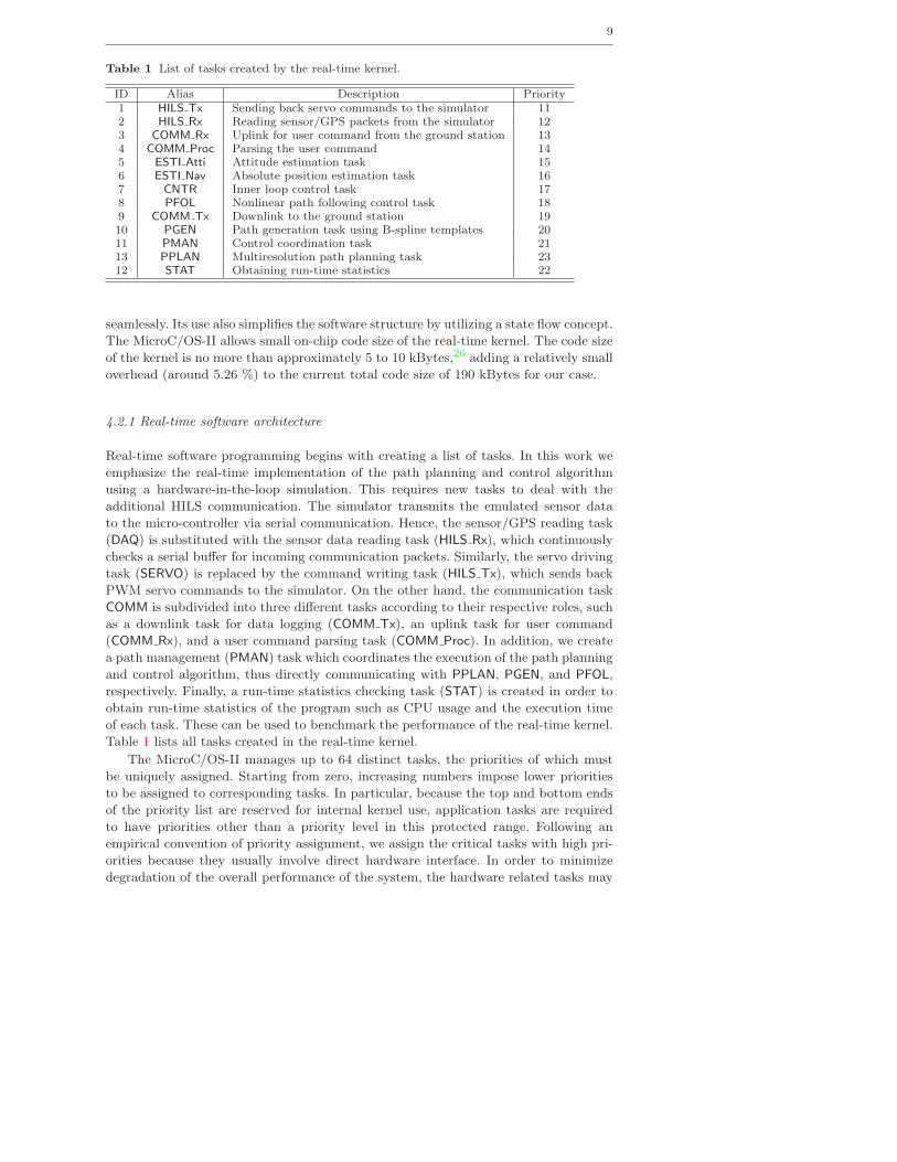
Table 1 List of tasks created by the real-time kernel.
ID Alias Description Priority1 HILS Tx Sending back servo commands to the simulator 112 HILS Rx Reading sensor/GPS packets from the simulator 123 COMM Rx Uplink for user command from the ground station 134 COMM Proc Parsing the user command 145 ESTI Atti Attitude estimation task 156 ESTI Nav Absolute position estimation task 167 CNTR Inner loop control task 178 PFOL Nonlinear path following control task 189 COMM Tx Downlink to the ground station 1910 PGEN Path generation task using B-spline templates 2011 PMAN Control coordination task 2113 PPLAN Multiresolution path planning task 2312 STAT Obtaining run-time statistics 22
seamlessly. Its use also simplifies the software structure by utilizing a state flow concept.
The MicroC/OS-II allows small on-chip code size of the real-time kernel. The code size
of the kernel is no more than approximately 5 to 10 kBytes,26 adding a relatively small
overhead (around 5.26 %) to the current total code size of 190 kBytes for our case.
4.2.1 Real-time software architecture
Real-time software programming begins with creating a list of tasks. In this work we
emphasize the real-time implementation of the path planning and control algorithm
using a hardware-in-the-loop simulation. This requires new tasks to deal with the
additional HILS communication. The simulator transmits the emulated sensor data
to the micro-controller via serial communication. Hence, the sensor/GPS reading task
(DAQ) is substituted with the sensor data reading task (HILS Rx), which continuously
checks a serial buffer for incoming communication packets. Similarly, the servo driving
task (SERVO) is replaced by the command writing task (HILS Tx), which sends back
PWM servo commands to the simulator. On the other hand, the communication task
COMM is subdivided into three different tasks according to their respective roles, such
as a downlink task for data logging (COMM Tx), an uplink task for user command
(COMM Rx), and a user command parsing task (COMM Proc). In addition, we create
a path management (PMAN) task which coordinates the execution of the path planning
and control algorithm, thus directly communicating with PPLAN, PGEN, and PFOL,
respectively. Finally, a run-time statistics checking task (STAT) is created in order to
obtain run-time statistics of the program such as CPU usage and the execution time
of each task. These can be used to benchmark the performance of the real-time kernel.
Table 1 lists all tasks created in the real-time kernel.
The MicroC/OS-II manages up to 64 distinct tasks, the priorities of which must
be uniquely assigned. Starting from zero, increasing numbers impose lower priorities
to be assigned to corresponding tasks. In particular, because the top and bottom ends
of the priority list are reserved for internal kernel use, application tasks are required
to have priorities other than a priority level in this protected range. Following an
empirical convention of priority assignment, we assign the critical tasks with high pri-
orities because they usually involve direct hardware interface. In order to minimize
degradation of the overall performance of the system, the hardware related tasks may
10
need proper synchronization with the hardware, hence demanding immediate atten-
tion. It follows that routine tasks that are required for the UAV to perform minimum
automatic control such as ESTI Atti, ESTI Nav, and CNTR are given lower priorities.
Finally, application-specific tasks such as PFOL, PGEN, and PPLAN are given even
lower priorities. This implies that these tasks can be activated whenever the highest
priority tasks relinquish the CPU. Table 1 shows the assigned priority for each task.
Note that the task COMM Tx is assigned with a lower priority because this task is less
critical to the autonomous operation of the UAV.
Having the required tasks created, we proceed to design a real-time software frame-
work by establishing the relationships between the tasks using the available kernel ser-
vices: A semaphore is utilized to control access to a globally shared object in order
to prevent it from being shared indiscriminately by several different tasks. Event flags
are used when a task needs to be synchronized with the occurrence of multiple events
or relevant tasks. For inter-task communication, a mailbox is employed to exchange a
message in order to convey information between tasks.
Figure 7 illustrates the overall real-time software architecture for the autopilot. In
the diagram two binary semaphores are utilized for two different objects corresponding
to the wireless modem and a reference path curve, respectively. Any task that requires
getting access to those objects needs to be blocked (by semaphore pending) until the
corresponding semaphore is either non-zero or is released (by semaphore posting). Con-
sequently, only one task has exclusive access to the objects at a time, which allows data
compatibility among different tasks. The event flags are posted by the triggering tasks
and are consumed by the pending tasks, allowing synchronization of two consecutive
tasks. Note that an event from the HILS Rx triggers a chain of routine tasks for pro-
cessing raw sensor data (ESTI Atti, ESTI Nav) and control implementation (CNTR).
A global data storage is used to hold all significant variables that can be referenced
by any task, while the global flags declaration block contains a number of event flag
groups used for synchronization of tasks. Each mailbox can hold a byte-length message
which is posted by a sender task with information indicated next to the data flow arrow
symbol. Each task receiving the message will empty the mailbox and wait for another
message to be posted. These mailboxes are employed to pass the results of one task to
another task. It should be noted that when the task PMAN triggers the task PPLAN,
the results of subsequent tasks are transmitted via mailboxes in the following order:
(PPLAN → PGEN → PMAN → PFOL).
4.2.2 Benefits of using a real-time kernel
Robustness: The real-time kernel provides many error handling capabilities during
deadlock situations. We have been able to resolve all possible deadlocks using the timing
features of the Semaphore-Pend or Flag-Pend operations. The kernel provides time-out
signals in the semaphore and flag calls with appropriate generated errors. These are
used to handle the unexpected latency or deadlock in the scheduling operation.
Flexibility and ease of maintenance: The entire architecture for the autopilot
software has been designed, while keeping in mind the object-oriented requirements
for an applications engineer. The real-time kernel provides an easy and natural way to
achieve this goal. The architecture has been designed to keep the code flexible enough
to allow adding higher level tasks, like the ones required to process and execute the
multi-resolution wavelet path planning algorithm. All this can be achieved without

11
HILS_Rx
PPLAN
STAT
CNTR
COMM_Rx
PFOLESTI_Nav
PMAN
COMM_Proc
PGEN
GLOBAL Data Storage
Global Flags Declaration
Use
rC
omm
and
Re f
. Cu r
ve
Phi
Ref
Mode 0: LoiteringMode 1: Regular
Goal
Postion to Go
Path
Seq
uenc
e
Ser
vo P
WM
s
ESTI_Atti
REAL TIME KERNEL
Event Flag
LEGEND
Flight Dynamics Simulator
HILS_TxWireless RF Modem
900MHz WirelessBinary
Ground Station
COMM_Tx
Wireless RF Modem
Contro
l Sta
tus
Ref
. cur
veup
date
Ref. curve
Mailbox Post
Mail box Semaphore
Data Flow
Con
trol
com
man
d
Fig. 7 The complete real-time software architecture for the path planning and control of theonboard UAV.
engrossing into the system level intricacies of handling and programming a micro-
controller/microprocessor. The flexibility of the architecture also makes it extremely
efficient to debug faults in low-level, mid-level or high-level tasks, without having to
re-code/interfere with the other tasks.
5 Hardware-in-the-loop Simulation Results
In this section we present the results of the hierarchical path control algorithm using
a small micro-controller in a real-time hardware-in-the-loop simulation environment.
The details of the implementation are discussed in the sequel.
5.1 Simulation scenario
The environment is a square area containing actual elevation data of a US state, of
dimension 128×128 units, which corresponds to 9.6×9.6 km. Taking into account the
available memory of the micro-controller, we choose the range and granularity of the
fine and coarse resolution levels. Cells at the fine resolution have dimensions 150×150
meters, which is slightly larger than the minimum turning radius of the UAV. The
minimum turn radius is approximately calculated for the vehicle flying at a constant
speed of VT = 20 [m/sec] with a bounded roll angle of |φ| ≤ 30◦, resulting in a minimum
turn radius of Rmin ≈ 70 [m].

12
A
B
C
D
E
F
G
H
I
p0
pf
pa
pb
Step Task description
A Initially, the UAV is loitering around the initial position with the circle radius Rl
B Calculate the first path segment from p0
to pa
C Break away from the loiter circle, start to follow the first path segmentD Calculate second segment from pa to pb, and transient pathE UAV is on the transient pathF Calculate the third path segment, and a transient pathG UAV is approaching the goal position, no path calculatedH The goal is reached, end of the path control, get on the loitering circleI UAV is loitering around the goal position pf
Fig. 8 Illustration of the real-time implementation of the proposed hierarchical path controlalgorithm.
The objective of the UAV is to generate and track a path from the initial posi-
tion to the final position while circumventing all obstacles above a certain elevation
threshold. Figure 8 illustrates the detailed implementation of the proposed path plan-
ning and control algorithm. Initially, the UAV is loitering around the initial position
p0 until a local path segment from p0 to pa is computed (Step A,B). Subsequently,
the path following controller is engaged to follow the path (Step C,D). At step D, the
UAV replans to compute a new path from the intermediate location pa to the goal,
resulting in the second local path segments from pa to pb. The first and second path
segments are stitched by a transient B-spline path assuring the continuity condition at
each intersection point (marked by black squares). This process iterates until the final
position pf is reached (Step H), when the UAV engages to loitering around the goal
location.
5.2 Simulation results
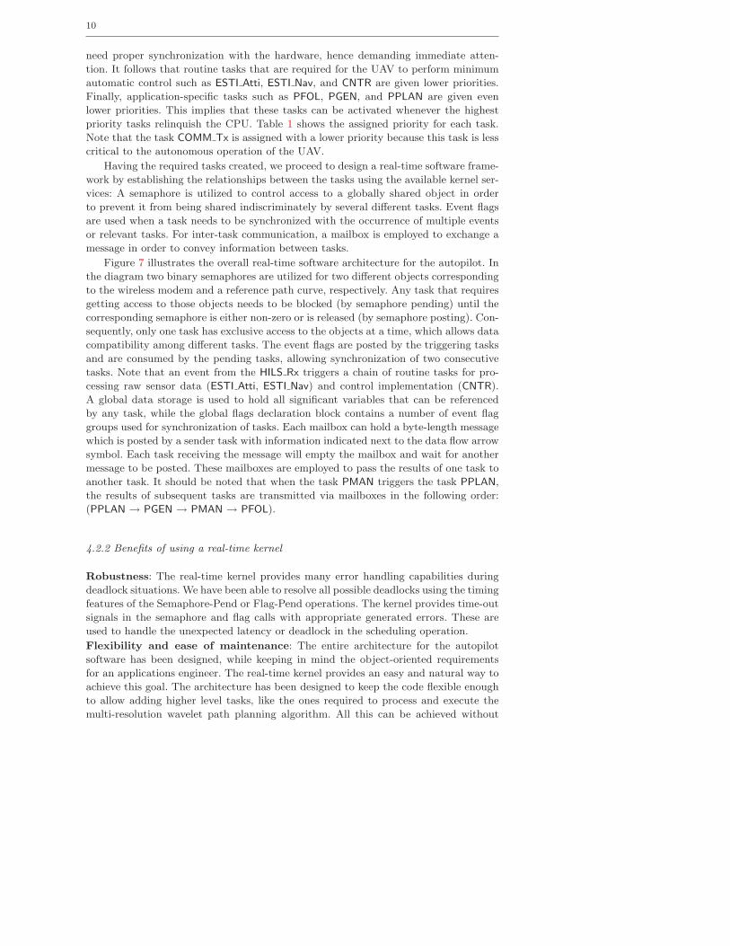
Figure 9 shows the simulation results of the hierarchical path control implementation.
Specifically, the plots on the right show the close-up view of the simulation. The chan-
nels are drawn by solid polygonal lines. The actual trajectory followed by the UAV is
also shown. The UAV smoothly follows the reference path while avoiding all possible
obstacles outside these channels. Finally, the UAV reaches the final destination in a
collision-free manner, as seen in Fig. 9(d).
13
0 50 1000
20
40
60
80
100
120
(a) t = 64.5 [sec]
0 50 1000
20
40
60
80
100
120
(b) t = 333.0 [sec]
0 50 1000
20
40
60
80
100
120
(c) t = 429.0 [sec]
0 50 1000
20
40
60
80
100
120
(d) t = 591.5 [sec]
Fig. 9 Hardware-in-the-loop simulation results of the hierarchical path control implementa-tion. The plots on the right show the close-up view of the simulation. At each instant, thechannel where the smooth path segment from the corresponding path template has to stay,is drawn by polygonal lines,. The actual path followed by the UAV is drawn on top of thereference path.
14
20 40 60 80 100 120 140 160 180 2000
10
20
30
40
50
60
70
80
90
100
# of samples
CP
U u
sage
[%]
CPU Usage
(a) CPU usage
20 40 60 80 100 120 140 160 180 20060
70
80
90
100
110
120
130
140
150
160
# of samples
# of
Con
text
sw
itch
Number of context switches per second
(b) Number of context switches per second
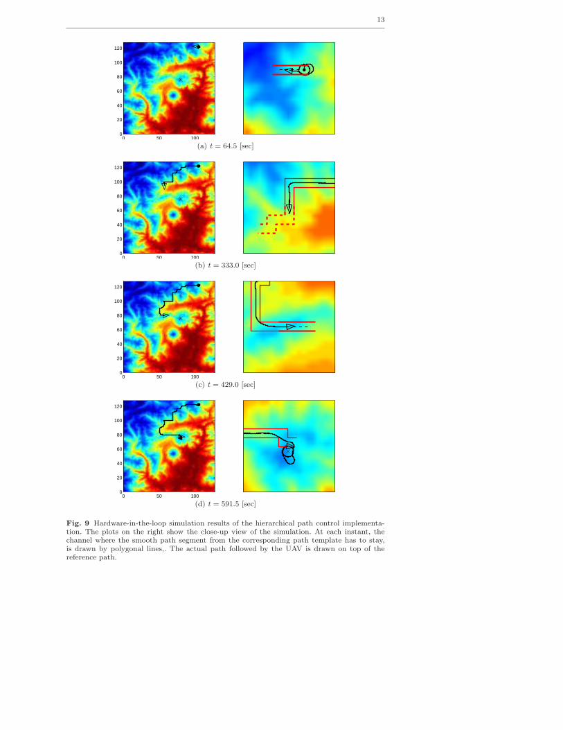
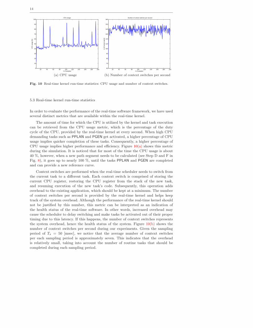
Fig. 10 Real-time kernel run-time statistics: CPU usage and number of context switches.
5.3 Real-time kernel run-time statistics
In order to evaluate the performance of the real-time software framework, we have used
several distinct metrics that are available within the real-time kernel.
The amount of time for which the CPU is utilized by the kernel and task execution
can be retrieved from the CPU usage metric, which is the percentage of the duty
cycle of the CPU, provided by the real-time kernel at every second. When high CPU
demanding tasks such as PPLAN and PGEN get activated, a higher percentage of CPU
usage implies quicker completion of these tasks. Consequently, a higher percentage of
CPU usage implies higher performance and efficiency. Figure 10(a) shows this metric
during the simulation. It is noticed that for most of the time the CPU usage is about
40 %, however, when a new path segment needs to be calculated (see Step D and F in
Fig. 8), it goes up to nearly 100 %, until the tasks PPLAN and PGEN are completed
and can provide a new reference curve.
Context switches are performed when the real-time scheduler needs to switch from
the current task to a different task. Each context switch is comprised of storing the
current CPU register, restoring the CPU register from the stack of the new task,
and resuming execution of the new task’s code. Subsequently, this operation adds
overhead to the existing application, which should be kept at a minimum. The number
of context switches per second is provided by the real-time kernel and helps keep
track of the system overhead. Although the performance of the real-time kernel should
not be justified by this number, this metric can be interpreted as an indication of
the health status of the real-time software. In other words, increased overhead may
cause the scheduler to delay switching and make tasks be activated out of their proper
timing due to this latency. If this happens, the number of context switches represents
the system overhead, hence the health status of the system. Figure 10(b) shows the
number of context switches per second during our experiments. Given the sampling
period of Ts = 50 [msec], we notice that the average number of context switches
per each sampling period is approximately seven. This indicates that the overhead
is relatively small, taking into account the number of routine tasks that should be
completed during each sampling period.

15
20 40 60 80 100 120 140 160 180 2000
10
20
30
40
50
60
70
80
90
100
# of samples
CP
U r
atio
[%]
CPU ratio between tasks
2
4
6
8
10
12
(a) CPU ratio over different tasks
20 40 60 80 100 120 140 160 180 2000
10
20
30
40
50
60
# of samples
Ave
rage
TE
T [m
sec]
Average Task Execution Time
2
4
6
8
10
12
(b) Mean tasks execution time
Fig. 11 Real-time kernel run-time statistics: CPU ratio vs. Mean tasks execution time
Individual task execution time is measured during run-time, by referencing a hook
function OSTaskSwHook() when a context switching is performed. This function cal-
culates the elapsed CPU time of the preempted task and updates a task-specific data
structure with this information. Subsequently, when a statistics hook function is called
by the real-time kernel, each task execution time TETi(k) is added together to get the
total execution time of all tasks. On the other hand, the CPU ratio of different tasks,
i.e., the percentage of time actually consumed by each task, is computed as follows,
πi(k) =TETi(k)
∑Ni=1 TETi(k)
× 100 [%], (1)
where πi(k) denotes a percentage of time consumed by ith task at kth time. Figure 11(a)
shows the run-time CPU ratio. Different colors are used to distinguish between different
tasks, as depicted by the colorbar on the right side of each figure.
Finally, the execution time of each task over the given sampling period Ts =
50 [msec] is calculated as follows,
TETi(k) =TETi(k)
(tk − tk−1)/Ts[msec], (2)
where tk denotes the actual time of the kth statistical sample. Equation (2) basically
calculates the mean value of the execution time of the ith task over one sampling
period. This metric is updated at every statistical sample. As shown in Fig. 11(b), this
metric helps us check if the total sum of execution times of different tasks exceeds the
given sampling period Ts.
6 Conclusions
We have implemented a hierarchical path planning and control of a small UAV on the
actual hardware platform. Using a high fidelity hardware-in-the-loop (HIL) simulation
environment, the proposed hierarchical path planning and control algorithm has been
validated through the on-line, real-time implementation on a small autopilot. By inte-
grating the control algorithms for path planning, path smoothing, and path following
16
under two real-time/near real-time implementations, it has been demonstrated that the
UAV equipped with a small autopilot having limited computational resources manages
to accomplish the mission objective of reaching the goal destination, while avoiding
obstacles. Emphasizing the use of a real-time kernel, we have discussed the implemen-
tation issues utilizing the kernel services, which allows flexibility of task management,
robustness of code execution, etc. Provided with quantitative metrics, we have shown
that the real-time kernel successfully accomplishes real-time operation of a small UAV
for a non-trivial, realistic, path planning scenario.
Acknowledgements Partial support for this work has been provided by NSF award no.CMS-0510259 and NASA award no. NNX08AB94A.
References
1. Balluchi, A., Berardi, L., Di Benedetto, M., Ferrari, A., Girasole, G., Sangiovanni-Vincentelli, A.L.: Integrated control-implementation design. In: Proceedings of the 41stIEEE Conference on Decision and Control, pp. 1337–1342. Las Vegas, NV (2002)
2. Beard, R.W., McLain, T.W., Goodrich, M., Anderson, E.P.: Coordinated Target Assign-ment and Intercept for Unmanned Air Vehicles. IEEE Transactions on Robotics andAutomation 18, 911–922 (2002)
3. Bellingham, J., Richards, A., How, J.: Receding horizon control of autonomous aerialvehicles. In: Proceedings of the American Control Conference, pp. 3741–3745. Anchorage,AK (2002)
4. Bortoff, S.A.: Path planning for UAVs. In: Proceedings of the American Control Confer-ence, pp. 364–368. Chicago, IL (2000)
5. Chandler, P., Pachter, M.: Research Issues in Autonomous Control of Tactical UAVs. In:Proceedings of the American Control Conference, pp. 394–398. Philadelphia, PA (1998)
6. Christophersen, H.B., Pickell, R.W., Neidhoefer, J.C., Koller, A.A., Kannan, S.K., John-son, E.N.: A compact guidance, navigation, and control system for unmanned aerial ve-hicles. Journal of Aerospace Computing, Information, and Communication 3(5), 187–213(2006)
7. Gelperin, D.: On the optimality of A∗. Artificial Intelligence 8(1), 69–76 (1977)8. Hall, C.: On board flight computers for flight testing small uninhabited aerial vehicles. In:
The 2002 45th Midwest Symposium on Circuits and Systems, vol. 2, pp. II–139 – II–143(2002)
9. Hart, P., Nilsson, N., Rafael, B.: A formal basis for the heuristic determination of minimumcost paths. IEEE Tans. Sys. Sci. and Cyb. 4, 100107 (1968)
10. Jang, J., Tomlin, C.: Autopilot design for the Stanford DragonFly UAV: validation throughhardware-in-the-loop simulation. In: AIAA Guidance, Navigation, and Control Conference,pp. AIAA 2001–4179. Montreal, Canada (2001)
11. Jang, J., Tomlin, C.: Design and Implementation of a Low Cost, Hierarchical and ModularAvionics Architecture for the DranfonFly UAVs. In: AIAA Guidance, Navigation, andControl Conference and Exhibit. Monterey, CA (2002). AIAA 2002-4465
12. Jang, J.S., Liccardo, D.: Small uav automation using MEMS. IEEE Aerospace and Elec-tronic Systems Magazine 22(5), 30–34 (2007)
13. Jang, J.S., Tomlin, C.: Longitudinal stability augmentation system design for the Drag-onFly UAV using a single GPS receiver. In: AIAA Guidance, Navigation, and ControlConference. Austin, TX (2003). AIAA 2003-5592
14. Jang, J.S., Tomlin, C.J.: Design and implementation of a low cost, hierarchical and modularavionics architecture for the dragonfly uavs. In: AIAA Guidance, Navigation, and ControlConference and Exhibit. Monterey, CA (2002)
15. Johnson, E.N., Proctor, A.A., Ha, J., Tannenbaum, A.R.: Development and Test of HighlyAutonomous Unmanned Aerial Vehicles. Journal of Aerospace Computing, Information,and Communication 1, 486–500 (2004)
16. Jung, D.: Hierarchical path planning and control of a small fixed-wing UAV: Theory andexperimental validation. Ph.D. thesis, Georgia Institute of Technology, Atlanta, GA (2007)

17
17. Jung, D., Levy, E.J., Zhou, D., Fink, R., Moshe, J., Earl, A., Tsiotras, P.: Design anddevelopment of a low-cost test-bed for undergraduate education in uavs. In: Proceedingsof the 44th IEEE Conference on Decision and Control, pp. 2739–2744. Seville, Spain (2005)
18. Jung, D., Tsiotras, P.: Inertial attitude and position reference system development fora small uav. In: AIAA Infotech at Aerospace. Rohnert Park, CA (2007). AIAA Paper07-2768
19. Jung, D., Tsiotras, P.: Modelling and hardware-in-the-loop simulation for a small un-manned aerial vehicle. In: AIAA Infotech at Aerospace. Rohnert Park, CA (2007). AIAAPaper 07-2763
20. Jung, D., Tsiotras, P.: Bank-to-turn control for a small uav using backstepping and pa-rameter adaptation. In: International Federation of Automatic Control (IFAC) WorldCongress. Seoul, Korea (2008)
21. Jung, D., Tsiotras, P.: Multiresolution on-line path planning for small unmanned aerialvehicles. In: American Control Conference. Seattle, WA (2008)
22. Jung, D., Tsiotras, P.: On-line path generation for small unmanned aerial vehicles using B-spline path templates. In: AIAA Guidance, Navigation and Control Conference. Honolulu,HI (2008). AIAA Paper 2008-7135
23. Kaminer, I., Yakimenko, O., Dobrokhodov, V., Lim, B.A.: Development and Flight Testingof GNC Algorithms Using a Rapid Flight Test Prototyping System. In: AIAA Guidance,Navigation, and Control Conference and Exhibit. Monterey, California (2002)
24. Kingston, D., Beard, R.W., McLain, T., Larsen, M., Ren, W.: Autonomous Vehicle Tech-nologies for Small Fixed Wing UAVs. In: 2nd AIAA Unmanned Unlimited Conference andWorkshop and Exhibit. Chicago, Illinois (2003)
25. Kingston, D.B., Beard, R.W.: Real-Time Attitude and Position Estimation for Small UAVsUsing Low-Cost Sensors. In: AIAA 3rd Unmanned Unlimited Technical Conference, Work-shop and Exhibit. Chicago, IL (2004)
26. Labrosse, J.J.: MicroC/OS-II - The Real-Time Kernel, 2 edn. CMPBooks, San Francisco,CA (2002)
27. McLain, T., Chandler, P., Pachter, M.: A Decomposition Strategy for Optimal Coordina-tion of Unmanned Air Vehicles. In: Proceedings of the American Control Conference, pp.369–373. Chicago, IL (2000)
28. McLain, T.W., Beard, R.W.: Coordination variables, coordination functions, and cooper-ative timing missions. Journal of Guidance, Control, and Dynamics 28(1), 150–161 (2005)
29. Palopoli, L., Pinello, C., Sangiovanni-Vincentelli, A.L., Elghaoui, L., Bicchi, A.: Synthesisof robust control systems under resource constraints. In: HSCC ’02: Proceedings of the5th International Workshop on Hybrid Systems: Computation and Control, pp. 337–350.Springer-Verlag, London, UK (2002)
30. Tsiotras, P., Bakolas, E.: A Hierarchical On-Line Path Planning Scheme using Wavelets.In: Proceedings of the European Control Conference, pp. 2806–2812. Kos, Greece (2007)