real time fpga signal processing for libera …real -time fpga signal processing for libera...
TRANSCRIPT

REAL -TIME FPGA SIGNAL PROCESSING FOR LIBERA BRILLIANCE SINGLE PASS
M. Znidarcic, M. Oblak, A. Kosicek, Instrumentation Technologies, Slovenia
Abstract Libera Brilliance is already a standard device for beam
position monitoring, while Libera Brilliance Single Pass, as its variant, is optimized for single pass position measurement. Complete signal processing on it has now been moved from embedded computer to FPGA. This enables complete hard real-time data processing. Together with implemented fast communication protocols (e.g. Gb Ethernet), it represents a reliable and deterministic building block for building fast feedback or feed-forward loops. The motivation, processing principles and first results are presented.
INTRODUCTION The aim of a single-pass position measurement, for
example in an FEL injector, is to resolve the bunch position from the information extrapolated from the very short pulses produced by a single bunch crossing the beam position monitor (BPM).
The Libera Brilliance Single Pass unit elaboration and implementation of the adapted calculation algorithm in the FPGA were done at Instrumentation Technologies [2]. In the following sections we present the implemented functionalities, algorithms and first test results.
ANALOG SIGNAL PROCESSING Four identical signal processing chains on the Libera
Brilliance Single Pass are composed of analog signal processing, digitalization on fast ADCs and digital signal processing implemented in the FPGA.
Analog single bunch signals from accelerator pickups excite the 500 MHz SAW filters. Due to relatively narrow filter bandwidth, the signal is lengthened to approx. 250 ns. Furthermore, the signal is filtered and amplified. To adapt it to input signal level, it can be attenuated with a variable attenuator with maximal attenuation of 31 dB (in 1dB steps). The output of the analog chain on the Libera Brilliance Single Pass is depicted in Figure 1.
Figure 1: Typical input signal (stripline) and the acquired signal after the analog chain (raw ADC values) on the Libera Brilliance Single Pass.
DIGITAL SIGNAL PROCESSING The entire data processing algorithm is implemented in
the Libera Brilliance Single Pass FPGA. The data processing works on an external trigger, which comes at the bunch repetition rate. Currently, the rate is limited to 200 Hz. The typical data processing cycle for one bunch consists of data acquisition in the ADC rate buffer, extraction of the data that contain the bunch information, and position calculation.
Data Extraction On every trigger event, the first 150 (current limitation)
samples of each channel in the ADC rate buffer are taken for data processing. The bunch information has to be within this batch of RAW data. The internal trigger delay, controlled through a CSPI (Control System Programming Interface) parameter, makes possible the accurate setting of the data position in the ADC rate buffer. The useful portion of the data is automatically extracted using CSPI single pass parameters (THRESHOLD, PRETRIGGER, POSTTRIGGER) and taken for further data processing – see Figure 2.
Figure 2: Parameter definition for single pass position calculation.
THRESHOLD is the basis for calculation. Before bunch arrival, only noise is acquired. By setting a threshold, a limit is set above which the signal is considered useful. To take into account only the useful part of the acquired buffer, PRETRIGGER and POSTTRIGGER samples are set. These two parameters can be freely set within predefined ranges. The algorithm checks whether at least one channel’s max ADC count (A, B, D, C) is higher than the threshold. For the threshold position, the first channel which rises over the threshold is taken into account.
WEPC78 Proceedings of FEL2009, Liverpool, UK
Stability and Synchronisation
682
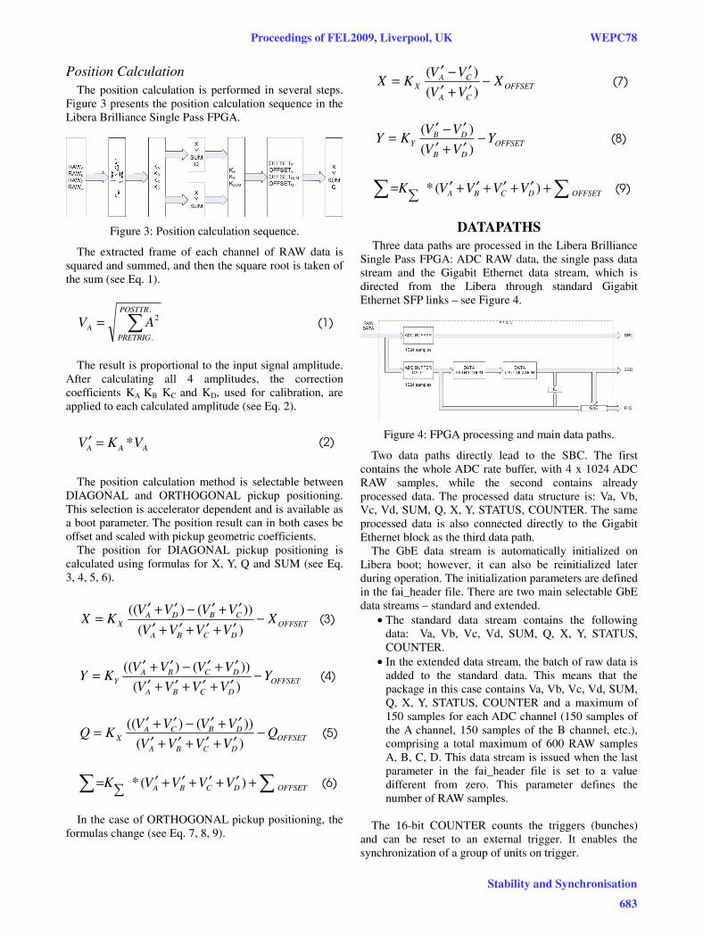
Position Calculation The position calculation is performed in several steps.
Figure 3 presents the position calculation sequence in the Libera Brilliance Single Pass FPGA.
Figure 3: Position calculation sequence.
The extracted frame of each channel of RAW data is squared and summed, and then the square root is taken of the sum (see Eq. 1).
∑=.
.
2POSTTR
PRETRIGA AV (1)
The result is proportional to the input signal amplitude.
After calculating all 4 amplitudes, the correction coefficients KA KB KC and KD, used for calibration, are applied to each calculated amplitude (see Eq. 2).
AAA VKV *=′ (2)
The position calculation method is selectable between
DIAGONAL and ORTHOGONAL pickup positioning. This selection is accelerator dependent and is available as a boot parameter. The position result can in both cases be offset and scaled with pickup geometric coefficients.
The position for DIAGONAL pickup positioning is calculated using formulas for X, Y, Q and SUM (see Eq. 3, 4, 5, 6).
OFFSETDCBA
CBDAX X
VVVV
VVVVKX −
′+′+′+′′+′−′+′=)(
))()(( (3)
OFFSETDCBA
DCBAY Y
VVVV
VVVVKY −
′+′+′+′′+′−′+′=)())()((
(4)
OFFSETDCBA
DBCAX Q
VVVV
VVVVKQ −
′+′+′+′′+′−′+′=)())()((
(5)
∑∑ +′+′+′+′∑
= OFFSETDCBA VVVVK )(* (6)
In the case of ORTHOGONAL pickup positioning, the
formulas change (see Eq. 7, 8, 9).
OFFSETCA
CAX X
VV
VVKX −
′+′′−′=)(
)( (7)
OFFSETDB
DBY Y
VV
VVKY −
′+′′−′=)(
)( (8)
∑∑ +′+′+′+′∑
= OFFSETDCBA VVVVK )(* (9)
DATAPATHS Three data paths are processed in the Libera Brilliance
Single Pass FPGA: ADC RAW data, the single pass data stream and the Gigabit Ethernet data stream, which is directed from the Libera through standard Gigabit Ethernet SFP links – see Figure 4.
Figure 4: FPGA processing and main data paths.
Two data paths directly lead to the SBC. The first contains the whole ADC rate buffer, with 4 x 1024 ADC RAW samples, while the second contains already processed data. The processed data structure is: Va, Vb, Vc, Vd, SUM, Q, X, Y, STATUS, COUNTER. The same processed data is also connected directly to the Gigabit Ethernet block as the third data path.
The GbE data stream is automatically initialized on Libera boot; however, it can also be reinitialized later during operation. The initialization parameters are defined in the fai_header file. There are two main selectable GbE data streams – standard and extended.
• The standard data stream contains the following data: Va, Vb, Vc, Vd, SUM, Q, X, Y, STATUS, COUNTER.
• In the extended data stream, the batch of raw data is added to the standard data. This means that the package in this case contains Va, Vb, Vc, Vd, SUM, Q, X, Y, STATUS, COUNTER and a maximum of 150 samples for each ADC channel (150 samples of the A channel, 150 samples of the B channel, etc.), comprising a total maximum of 600 RAW samples A, B, C, D. This data stream is issued when the last parameter in the fai_header file is set to a value different from zero. This parameter defines the number of RAW samples.
The 16-bit COUNTER counts the triggers (bunches)
and can be reset to an external trigger. It enables the synchronization of a group of units on trigger.
Proceedings of FEL2009, Liverpool, UK WEPC78
Stability and Synchronisation
683
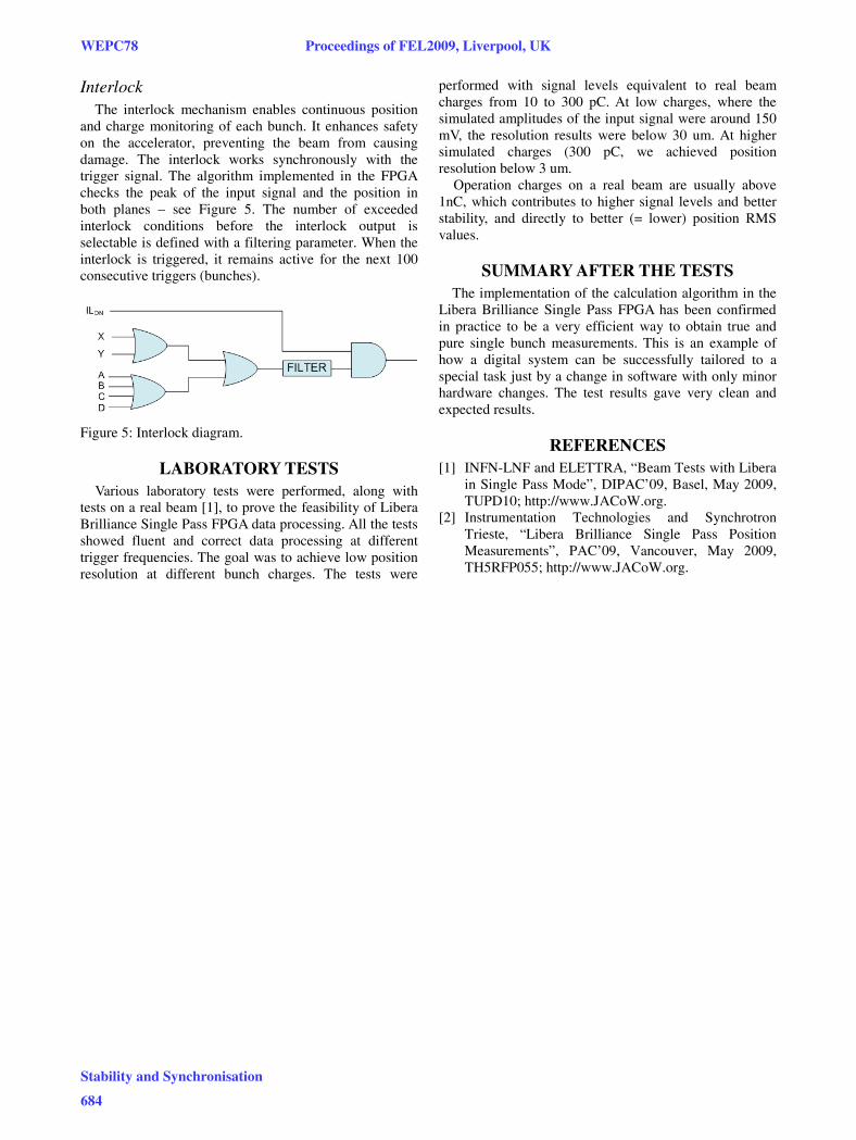
Interlock The interlock mechanism enables continuous position
and charge monitoring of each bunch. It enhances safety on the accelerator, preventing the beam from causing damage. The interlock works synchronously with the trigger signal. The algorithm implemented in the FPGA checks the peak of the input signal and the position in both planes – see Figure 5. The number of exceeded interlock conditions before the interlock output is selectable is defined with a filtering parameter. When the interlock is triggered, it remains active for the next 100 consecutive triggers (bunches).
Figure 5: Interlock diagram.
LABORATORY TESTS Various laboratory tests were performed, along with
tests on a real beam [1], to prove the feasibility of Libera Brilliance Single Pass FPGA data processing. All the tests showed fluent and correct data processing at different trigger frequencies. The goal was to achieve low position resolution at different bunch charges. The tests were
performed with signal levels equivalent to real beam charges from 10 to 300 pC. At low charges, where the simulated amplitudes of the input signal were around 150 mV, the resolution results were below 30 um. At higher simulated charges (300 pC, we achieved position resolution below 3 um.
Operation charges on a real beam are usually above 1nC, which contributes to higher signal levels and better stability, and directly to better (= lower) position RMS values.
SUMMARY AFTER THE TESTS The implementation of the calculation algorithm in the
Libera Brilliance Single Pass FPGA has been confirmed in practice to be a very efficient way to obtain true and pure single bunch measurements. This is an example of how a digital system can be successfully tailored to a special task just by a change in software with only minor hardware changes. The test results gave very clean and expected results.
REFERENCES [1] INFN-LNF and ELETTRA, “Beam Tests with Libera
in Single Pass Mode”, DIPAC’09, Basel, May 2009, TUPD10; http://www.JACoW.org.
[2] Instrumentation Technologies and Synchrotron Trieste, “Libera Brilliance Single Pass Position Measurements”, PAC’09, Vancouver, May 2009, TH5RFP055; http://www.JACoW.org.
WEPC78 Proceedings of FEL2009, Liverpool, UK
Stability and Synchronisation
684