real-time edge software user guide
TRANSCRIPT

Real-time Edge Software User Guide
NXP Semiconductors Document identifier: REALTIMEEDGEUGUser Guide Rev. 2.0, 29-Jul-2021

ContentsChapter 1 Introduction........................................................................................... 8
1.1 Real-time Edge software........................................................................................................... 81.2 Real-time Edge Software Yocto Project.................................................................................... 81.3 Supported NXP platforms..........................................................................................................81.4 Related documentation..............................................................................................................81.5 Acronyms and abbreviations..................................................................................................... 9
Chapter 2 Release notes..................................................................................... 122.1 What's new.............................................................................................................................. 12
2.1.1 What's new in Real-time Edge software v2.0............................................................................122.1.2 What's new in OpenIL v1.11..................................................................................................... 132.1.3 What's new in OpenIL v1.10..................................................................................................... 132.1.4 What's new in OpenIL v1.9....................................................................................................... 142.1.5 What's new in OpenIL v1.8....................................................................................................... 152.1.6 What's new in OpenIL v1.7....................................................................................................... 152.1.7 What's new in OpenIL v1.6....................................................................................................... 162.1.8 What's new in OpenIL v1.5....................................................................................................... 162.1.9 What's new in OpenIL v1.4....................................................................................................... 16
2.2 Feature Support Matrix............................................................................................................172.3 Open, fixed, and closed issues................................................................................................19
Chapter 3 Real-time System................................................................................213.1 Preempt-RT Linux................................................................................................................... 21
3.1.1 System Real-time Latency tests................................................................................................213.1.1.1 Running Cyclictest....................................................................................................................... 21
3.1.2 Real-time application development........................................................................................... 213.2 BareMetal................................................................................................................................ 22
3.2.1 Overview .................................................................................................................................. 223.2.1.1 BareMetal framework...................................................................................................................223.2.1.2 Supported platforms.....................................................................................................................24
3.2.2 Getting started...........................................................................................................................243.2.2.1 Hardware and software requirements..........................................................................................243.2.2.2 Hardware setup............................................................................................................................25
3.2.2.2.1 i.MX 8M Mini EVK and i.MX 8M Plus EVK board......................................................... 253.2.2.2.2 LS1028ARDB, LX2160ARDB, LS1043ARDB, or LS1046ARDB.................................. 253.2.2.2.3 LS1021A-IoT board.......................................................................................................25
3.2.2.3 Building the BareMetal images from U-Boot source code........................................................... 263.2.2.3.1 Building BareMetal binary for slave cores.....................................................................27
3.2.2.4 Building the image through Yocto................................................................................................ 273.2.2.4.1 Getting Real-time Edge software.................................................................................. 273.2.2.4.2 Building the BareMetal images..................................................................................... 283.2.2.4.3 Booting up the Linux with BareMetal............................................................................ 28
3.2.3 Running examples.................................................................................................................... 293.2.3.1 Preparing the console.................................................................................................................. 293.2.3.2 Running the BareMetal binary..................................................................................................... 29
3.2.4 Development based on BareMetal framework.......................................................................... 303.2.4.1 Developing the BareMetal application......................................................................................... 303.2.4.2 Example software........................................................................................................................ 30
3.2.4.2.1 Main file app.c...............................................................................................................30
NXP Semiconductors
Real-time Edge Software User Guide, Rev. 2.0, 29-Jul-2021User Guide 2 / 236

3.2.4.2.2 Common header files....................................................................................................313.2.4.2.3 GPIO file....................................................................................................................... 313.2.4.2.4 I2C file...........................................................................................................................323.2.4.2.5 IRQ file.......................................................................................................................... 333.2.4.2.6 QSPI file........................................................................................................................333.2.4.2.7 IFC................................................................................................................................ 353.2.4.2.8 Ethernet........................................................................................................................ 363.2.4.2.9 USB file......................................................................................................................... 373.2.4.2.10 PCIe file...................................................................................................................... 383.2.4.2.11 CAN file.......................................................................................................................393.2.4.2.12 ENETC file.................................................................................................................. 403.2.4.2.13 SAI file.........................................................................................................................40
3.2.4.3 ICC module.................................................................................................................................. 443.2.4.3.1 ICC examples............................................................................................................... 47
3.2.4.4 Hardware resource allocation...................................................................................................... 483.2.4.4.1 LS1021A-IoT board.......................................................................................................483.2.4.4.2 LS1028ARDB board..................................................................................................... 523.2.4.4.3 LS1043ARDB or LS1046ARDB board..........................................................................553.2.4.4.4 LX2160ARDB board..................................................................................................... 583.2.4.4.5 i.MX 8M Mini EVK and i.MX 8M Plus EVK board......................................................... 58
3.3 Jailhouse................................................................................................................................. 603.3.1 Overview................................................................................................................................... 603.3.2 Running PREEMPT_RT Linux in Inmate.................................................................................. 60
3.3.2.1 i.MX 8M Plus EVK........................................................................................................................603.3.2.2 LS1028ARDB...............................................................................................................................613.3.2.3 LS1046ARDB...............................................................................................................................61
3.3.3 Running Jailhouse Examples In Inmate....................................................................................623.3.3.1 i.MX 8M Plus EVK........................................................................................................................623.3.3.2 LS1028ARDB Jailhouse example in Inmate................................................................................ 633.3.3.3 LS1046ARDB Jailhouse example................................................................................................64
Chapter 4 Real-time Networking..........................................................................654.1 Time Sensitive Networking (TSN) on NXP platforms.............................................................. 65
4.1.1 TSN hardware capability........................................................................................................... 654.1.2 TSN configuration..................................................................................................................... 65
4.1.2.1 Using Linux traffic control (tc)...................................................................................................... 664.1.2.2 Tsntool......................................................................................................................................... 67
4.1.2.2.1 Tsntool User Manual.....................................................................................................674.1.2.3 Remote configuration using NETCONF/YANG............................................................................774.1.2.4 Web-based configuration............................................................................................................. 78
4.1.2.4.1 Setting up web server................................................................................................... 784.1.2.4.2 Remote configuration....................................................................................................80
4.1.3 TSN on i.MX 8M Plus................................................................................................................824.1.3.1 Test environment......................................................................................................................... 824.1.3.2 Clock synchronization.................................................................................................................. 834.1.3.3 Qbv.............................................................................................................................................. 844.1.3.4 Qbu.............................................................................................................................................. 844.1.3.5 Qav.............................................................................................................................................. 87
4.1.4 TSN on LS1028A...................................................................................................................... 884.1.4.1 TSN configuration on ENETC...................................................................................................... 88
4.1.4.1.1 Clock synchronization................................................................................................... 884.1.4.1.2 Qbv............................................................................................................................... 894.1.4.1.3 Qbu............................................................................................................................... 924.1.4.1.4 Qci.................................................................................................................................93
NXP SemiconductorsContents
Real-time Edge Software User Guide, Rev. 2.0, 29-Jul-2021User Guide 3 / 236

4.1.4.1.5 Qav............................................................................................................................... 974.1.4.2 TSN configuration on Felix switch................................................................................................98
4.1.4.2.1 Linux switch configuration.............................................................................................984.1.4.2.2 Clock synchronization................................................................................................... 994.1.4.2.3 Qbv test setup for LS1028ARDB................................................................................ 1004.1.4.2.4 Qbu............................................................................................................................. 1014.1.4.2.5 Qci...............................................................................................................................1034.1.4.2.6 Qav............................................................................................................................. 1094.1.4.2.7 802.1CB...................................................................................................................... 1114.1.4.2.8 TSN stream identification............................................................................................113
4.1.5 TSN on LS1021A-TSN............................................................................................................1154.1.5.1 Topology.................................................................................................................................... 1154.1.5.2 SJA1105 Linux support..............................................................................................................1164.1.5.3 Synchronized 802.1Qbv demo...................................................................................................119
4.2 GenAVB/TSN stack...............................................................................................................1244.2.1 Introduction............................................................................................................................. 124
4.2.1.1 gPTP stack.................................................................................................................................1244.2.1.2 SRP stack.................................................................................................................................. 1244.2.1.3 TSN Endpoint example application............................................................................................1244.2.1.4 Supported configurations........................................................................................................... 125
4.2.2 Building the image through Yocto........................................................................................... 1254.2.3 GenAVB/TSN stack start/stop.................................................................................................1264.2.4 Use cases description............................................................................................................. 126
4.2.4.1 gPTP Bridge...............................................................................................................................1264.2.4.2 gPTP Endpoint...........................................................................................................................1274.2.4.3 gPTP multiple domains.............................................................................................................. 127
4.2.4.3.1 Requirements..............................................................................................................1274.2.4.3.2 gPTP Stack Configuration...........................................................................................1284.2.4.3.3 Evaluation Instructions................................................................................................129
4.2.4.4 AVB Bridge................................................................................................................................ 1294.2.4.4.1 Requirements..............................................................................................................1294.2.4.4.2 AVB network configuration..........................................................................................1304.2.4.4.3 Setup preparation....................................................................................................... 1314.2.4.4.4 Evaluation instructions................................................................................................ 132
4.2.4.5 TSN endpoint sample application.............................................................................................. 1344.2.4.5.1 Requirements..............................................................................................................1344.2.4.5.2 Configuring GenAVB/TSN stack and example applications....................................... 1344.2.4.5.3 TSN network configuration..........................................................................................1344.2.4.5.4 Setup preparation....................................................................................................... 1354.2.4.5.5 Evaluation instructions................................................................................................ 138
4.2.5 Configuration files................................................................................................................... 1424.2.5.1 System....................................................................................................................................... 1424.2.5.2 gPTP.......................................................................................................................................... 143
4.2.5.2.1 General....................................................................................................................... 1434.2.5.2.2 Grandmaster parameters............................................................................................1454.2.5.2.3 Automotive parameters...............................................................................................1464.2.5.2.4 Timing......................................................................................................................... 1474.2.5.2.5 PORTn........................................................................................................................ 147
4.2.5.3 SRP............................................................................................................................................1484.2.6 Log files...................................................................................................................................148
4.2.6.1 gPTP Endpoint...........................................................................................................................1484.2.6.2 gPTP Bridge...............................................................................................................................1514.2.6.3 SRP Bridge................................................................................................................................ 1514.2.6.4 TSN Endpoint example application............................................................................................152
4.2.6.4.1 Main TSN task............................................................................................................ 152
NXP SemiconductorsContents
Real-time Edge Software User Guide, Rev. 2.0, 29-Jul-2021User Guide 4 / 236

4.2.6.4.2 Network socket........................................................................................................... 1534.2.6.4.3 Application socket....................................................................................................... 154
4.3 IEEE 1588/802.1AS...............................................................................................................1544.3.1 Introduction............................................................................................................................. 1544.3.2 IEEE 1588 device types.......................................................................................................... 1544.3.3 IEEE 802.1AS time-aware systems........................................................................................ 1554.3.4 Software stacks.......................................................................................................................155
4.3.4.1 linuxptp stack............................................................................................................................. 1554.3.4.2 NXP GenAVB/TSN gPTP stack................................................................................................. 156
4.3.5 Quick Start for IEEE 1588....................................................................................................... 1564.3.5.1 Ordinary clock verification..........................................................................................................1564.3.5.2 Boundary clock verification........................................................................................................ 1574.3.5.3 Transparent clock verification.................................................................................................... 158
4.3.6 Quick Start for IEEE 802.1AS................................................................................................. 1594.3.6.1 Time-aware end station verification........................................................................................... 1594.3.6.2 Time-aware bridge verification...................................................................................................160
4.3.7 Long term test......................................................................................................................... 1604.3.7.1 linuxptp basic synchronization................................................................................................... 160
4.3.8 Known issues and limitations.................................................................................................. 1624.4 Networking.............................................................................................................................163
4.4.1 Q-in-Q on LS1028A Felix switch............................................................................................. 1634.4.2 VCAP on LS1028A Felix switch.............................................................................................. 164
Chapter 5 Protocols........................................................................................... 1685.1 EtherCAT...............................................................................................................................168
5.1.1 Introduction............................................................................................................................. 1685.1.2 IGH EtherCAT architecture..................................................................................................... 1685.1.3 EtherCAT protocol...................................................................................................................1695.1.4 IGH EtherCAT Device Modules.............................................................................................. 1705.1.5 IGH EtherCAT integration and setup...................................................................................... 170
5.1.5.1 Building IGH EtherCAT.............................................................................................................. 1705.1.5.2 IGH EtherCAT setup.................................................................................................................. 170
5.1.6 real-time-edge-servo stack......................................................................................................1725.1.6.1 CoE network.............................................................................................................................. 1725.1.6.2 Libnservo architecture................................................................................................................1735.1.6.3 real-time-edge-servo Xml configuration..................................................................................... 173
5.1.6.3.1 Master element........................................................................................................... 1745.1.6.3.2 Axle element............................................................................................................... 177
5.1.6.4 Test............................................................................................................................................ 1775.1.6.4.1 Hardware preparation................................................................................................. 1775.1.6.4.2 Software preparation...................................................................................................1785.1.6.4.3 CoE network detection................................................................................................1785.1.6.4.4 Start test......................................................................................................................179
5.2 FlexCAN and CAN Open.......................................................................................................1805.2.1 Introduction............................................................................................................................. 181
5.2.1.1 CAN bus.....................................................................................................................................1815.2.1.2 CANopen................................................................................................................................... 182
5.2.2 FlexCAN integration in Real-time Edge.................................................................................. 1845.2.2.1 LS1021AIOT CAN resource allocation...................................................................................... 1845.2.2.2 Introducing the function of CAN example code..........................................................................185
5.2.3 Running a CAN application..................................................................................................... 1865.2.3.1 Hardware preparation for LS1021-IoT....................................................................................... 1865.2.3.2 Hardware preparation for LS1028ARDB....................................................................................1885.2.3.3 Compiling the CANopen-app binary for the master node.......................................................... 188
NXP SemiconductorsContents
Real-time Edge Software User Guide, Rev. 2.0, 29-Jul-2021User Guide 5 / 236

5.2.3.4 Running the CANopen application.............................................................................................1895.2.3.5 Running the SocketCAN commands......................................................................................... 1925.2.3.6 Testing CAN bus........................................................................................................................192
5.3 OPC UA.................................................................................................................................1935.3.1 OPC introduction.....................................................................................................................1935.3.2 The node model...................................................................................................................... 1945.3.3 Node Namespaces..................................................................................................................1945.3.4 Node classes...........................................................................................................................1955.3.5 Node graph and references.................................................................................................... 1955.3.6 Open62541............................................................................................................................. 196
5.4 NETCONF/YANG..................................................................................................................1975.4.1 Overview................................................................................................................................. 1975.4.2 Netopeer2............................................................................................................................... 198
5.4.2.1 Overview.................................................................................................................................... 1985.4.2.2 Installing Netopeer2-cli on Ubuntu18.04....................................................................................1995.4.2.3 Sysrepo......................................................................................................................................2005.4.2.4 Netopeer2 server....................................................................................................................... 2005.4.2.5 Netopeer2 client.........................................................................................................................2005.4.2.6 Workflow in application practice.................................................................................................201
5.4.3 Configuration...........................................................................................................................2015.4.3.1 Enabling NETCONF feature...................................................................................................... 2015.4.3.2 Netopeer2-server....................................................................................................................... 2025.4.3.3 Netopeer2-cli .............................................................................................................................202
5.4.3.3.1 Netopeer2 CLI commands.......................................................................................... 2025.4.3.3.2 Netopeer2 CLI datastore.............................................................................................205
5.4.3.4 Sysrepod....................................................................................................................................2055.4.3.5 Sysrepocfg................................................................................................................................. 2065.4.3.6 Sysrepoctl.................................................................................................................................. 2065.4.3.7 Operation examples...................................................................................................................2075.4.3.8 Application scenarios................................................................................................................. 209
5.4.4 Troubleshooting...................................................................................................................... 2125.5 Graphics on LS1028A........................................................................................................... 213
5.5.1 GPU........................................................................................................................................ 2135.5.2 Wayland and Weston.............................................................................................................. 2165.5.3 CSI Camera............................................................................................................................ 220
5.6 Wireless on LS1028A............................................................................................................2235.6.1 NFC.........................................................................................................................................223
5.6.1.1 Introduction................................................................................................................................ 2235.6.1.2 PN7120 features........................................................................................................................ 2245.6.1.3 Hardware preparation................................................................................................................ 2245.6.1.4 Software preparation..................................................................................................................2245.6.1.5 Testing the NFC click board.......................................................................................................224
5.6.2 Bluetooth Low Energy............................................................................................................. 2255.6.2.1 Introduction................................................................................................................................ 2255.6.2.2 Bluetooth Low Energy................................................................................................................2265.6.2.3 Features.....................................................................................................................................2265.6.2.4 Hardware preparation................................................................................................................ 2265.6.2.5 Software preparation..................................................................................................................2275.6.2.6 Testing the BLE P click board....................................................................................................228
5.6.3 BEE......................................................................................................................................... 2305.6.3.1 BEE/ZigBEE...............................................................................................................................2305.6.3.2 Introduction................................................................................................................................ 2305.6.3.3 Features.....................................................................................................................................2305.6.3.4 Hardware preparation................................................................................................................ 2305.6.3.5 Software preparation..................................................................................................................231
NXP SemiconductorsContents
Real-time Edge Software User Guide, Rev. 2.0, 29-Jul-2021User Guide 6 / 236

5.6.3.6 Testing the BEE click board.......................................................................................................232
Chapter 6 Revision history.................................................................................233
NXP SemiconductorsContents
Real-time Edge Software User Guide, Rev. 2.0, 29-Jul-2021User Guide 7 / 236

Chapter 1Introduction1.1 Real-time Edge softwareReal-time Edge Software is an evolved version of Open Industrial Linux (OpenIL) for real-time and deterministic systems indifferent fields. The key technology components include Real-time Networking, Real-time System, and Industrial.
• The Real-time Networking includes TSN technology, TSN standards, management, configuration, and applications.Networking and redundancy features are also supported.
• The Real-time System includes PREEMPT_RT Linux, Jailhouse, and U-Boot based BareMetal framework and the differentcombinations between these systems.
• The 'Protocols' component includes support for industry standard protocols such as EtherCAT, CoE, OPC-UA, and so on.
This document describes the features and implementation of Real-time Edge Software on NXP hardware platforms.
1.2 Real-time Edge Software Yocto ProjectFor using Yocto build environment, refer to the Real-time Edge Yocto Project User Guide.
The Real-time Edge Yocto Project User Guide describes how to build an Real-time Edge image for both i.MX and QorIQ boardsby using a Yocto Project build environment.
1.3 Supported NXP platformsThe following table lists the NXP hardware SoCs and boards that support the Real-time Edge software.
Table 1. Supported NXP platforms
Platform Architecture Boot
i.MX 6ULL EVK Arm v7 SD
i.MX 8M Mini EVK Arm v8 SD
i.MX 8M Plus EVK Arm v8 SD
LS1028ARDB Arm v8 SD
LS1021AIOT Arm v7 SD
LS1021ATSN Arm v7 SD
LS1021ATWR Arm v7 SD
LS1012ARDB Arm v8 QSPI
LS1043ARDB Arm v8 SD
LS1046ARDB Arm v8 SD
LS1046AFRWY Arm v8 SD
LX2160ARDB Arm v8 SD
LX2160A Rev2 Arm v8 SD
1.4 Related documentationFor using Yocto build environment, refer to the Real-time Edge Yocto Project User Guide on the URL http://nww.preview.nxp.com/design/software/development-software/real-time-edge-software:REALTIME-EDGE-SOFTWARE.
NXP Semiconductors
Real-time Edge Software User Guide, Rev. 2.0, 29-Jul-2021User Guide 8 / 236

Refer to the following guides for detailed instructions on booting up and setting up the relevant boards.
• i.MX 6ULL EVK Quick Start Guide
• i.MX 8M Mini EVK Quick Start Guide
• i.MX 8M Plus EVK Quick Start Guide
• LS1028ARDB Quick Start Guide
• LS1021AIoT Getting Started Guide
• LS1021ATSN Getting Started Guide
• LS1021ATWR Getting Started Guide
• LS1012ARDB Getting Started Guide
• LS1043ARDB Getting Started Guide
• LS1046ARDB Getting Started Guide
• LS1046AFRWY Getting Started Guide
• LX2160A/LX2160A-Rev2 RDB Quick Start Guide
1.5 Acronyms and abbreviationsThe following table lists the acronyms used in this document.
Table 2. Acronyms and abbreviations
Term Description
AVB Audio video bridging
BC Boundary clock
BLE Bluetooth low energy
BMC Best master clock
CA Client application
CAN Controller area network
CBS Credit-based shaper
DEI Drop eligibility indication
DP Display port
EtherCAT Ethernet for control automation technology
ECU Electronic control units
FDB Forwarding data base
FQTSS Forwarding and queuing enhancements for time-sensitive streams
FMan Frame manager
GPU General processor unit
ICMP Internet control message protocol
IEEE Institute of electrical and electronics engineers
Table continues on the next page...
NXP SemiconductorsIntroduction
Real-time Edge Software User Guide, Rev. 2.0, 29-Jul-2021User Guide 9 / 236

Table 2. Acronyms and abbreviations (continued)
Term Description
IETF Internet engineering task force
IPC Inter-processor communication
KM Key management
LBT Latency and bandwidth tester
MAC Medium access control
NFC Near field communication
NCI NFC controller interface
NMT Network management
OC Ordinary clock
OpenIL Open industry Linux
OPC Open platform communications
OP-TEE Open portable trusted execution environment
OS Operating system
OTA Over-the-air
OTPMK One-time programmable master key
PCP Priority code point
PDO Process data object
PHC PTP hardware clock
PIT Packet inter-arrival times
PLC programmable logic controller
PTP Precision time protocol
QSPI Queued serial peripheral interface
RCW Reset configuration word
REE Rich execution environment
RPC Remote procedure call
RTEdge Real-time Edge
RTC Real-time clock
RTT Round-trip times
SABRE Smart application blueprint for rapid engineering
SDO Service data object
SPI Serial periphery interface
SRP Stream reservation protocol
Table continues on the next page...
NXP SemiconductorsIntroduction
Real-time Edge Software User Guide, Rev. 2.0, 29-Jul-2021User Guide 10 / 236

Table 2. Acronyms and abbreviations (continued)
Term Description
SRK Single root key
TA Trusted application
TAS Time-aware scheduler
TC Traffic classification
TCP Transmission control protocol
TEE Trusted execution environment
TFTP Trivial file transfer protocol
TSN Time sensitive networking
TZASC Trust zone address space controller
UDP User datagram protocol
VLAN Virtual local area network
NXP SemiconductorsIntroduction
Real-time Edge Software User Guide, Rev. 2.0, 29-Jul-2021User Guide 11 / 236

Chapter 2Release notes
2.1 What's newThe following sections describe the new features for each release.
2.1.1 What's new in Real-time Edge software v2.0• Based on Yocto project 3.2 (Gatesgarth)
• Real-time System
— PREEMPT-RT Linux
— Heterogeneous architecture
◦ BareMetal: PREEMPT-RT Linux on A core + BareMetal architecture on A core
▪ i.MX 8M Plus EVK, i.MX 8M Mini EVK, LS1028ARDB, LS1046ARDB, LS1043ARDB, LS1021A-IoT
◦ Jailhouse: PREEMPT-RT Linux on A core + Jailhouse + PREEMPT-RT Linux on A core
▪ i.MX 8M Plus EVK, LS1028ARDB, LS1046ARDB
• Real-time Networking
— TSN
◦ TSN Standards
▪ IEEE 802.1Qav
▪ IEEE 802.1Qbv
▪ IEEE 802.1Qbu
▪ IEEE 802.1Qci
▪ IEEE 802.1CB
▪ IEEE 802.1AS-2020 (gPTP)
▪ IEEE 802.1Qat-2010 (SRP)
◦ TSN Configurations
▪ Linux tc command and tsntool
▪ NETCONF/YANG
▪ Dynamic TSN configuration - web-based TSN configuration, dynamic topology discovery
◦ TSN Applications
▪ Example for real-time traffic processing
— Networking
◦ 802.1 Q-in-Q
◦ VCAP tc flower chain mode
▪ Priority set, VLAN tag push/pop/modify, Policer Burst and Rate Configuration, drop/trap/redirect
• Industrial
— EtherCAT master
NXP Semiconductors
Real-time Edge Software User Guide, Rev. 2.0, 29-Jul-2021User Guide 12 / 236

◦ IGH EtherCAT master stack
◦ Native EtherCAT-capable network driver module (i.MX 8M Mini EVK)
— FlexCAN
◦ SocketCAN on Linux kernel
— CANOpen
◦ CANOpen master and slave example code
— CoE: CANOpen over EtherCAT
◦ CiA402(DS402) profile framework based on IGH CoE interface
◦ EtherCAT CoE 6-8 axis control (i.MX 8M Mini EVK)
— OPC-UA/OPC-UA pub/sub
◦ open62541
— Modbus
◦ Modbus master and slave
◦ Modbus-RTU
◦ Modbus-TCP
◦ Modbus-ASCII
• New Added Platform
— i.MX 6ULL EVK
2.1.2 What's new in OpenIL v1.11What’s New:
• TSN
— 802.1AS-2020
◦ Initial support for multi-domain on i.MX 8M Plus and LS1028A
• Hardware
— i.MX 8M Plus silicon A1
• Linux Kernel
— LTS 5.4.70 for i.MX 8 Series
• U-Boot
— v2020.04 for i.MX 8 Series
• BareMetal
— v2020.04 for Layerscape and i.MX 8 Series
— i.MX 8M Plus EVK
2.1.3 What's new in OpenIL v1.10What’s New:
• TSN
— VCAP chain mode
— GenAVB/TSN stack
NXP SemiconductorsRelease notes
Real-time Edge Software User Guide, Rev. 2.0, 29-Jul-2021User Guide 13 / 236
• Real-time
— PREEMPT-RT 5.4 on i.MX 8M Mini
◦ Ethernet
◦ PCIe
◦ GPIO
◦ DSI
• BareMetal
— i.MX 8M Mini EVK (A core to A core)
◦ ICC
◦ Ethernet
◦ GPIO
• OpenIL framework
— Board
◦ i.MX 8M Mini platform
▪ GPU: OpenGL ES
▪ Display: OpenGL ES, Weston, DSI-MIPI, CSI-MIPI
2.1.4 What's new in OpenIL v1.9What’s New:
• TSN
— tc flower support for Qbu and Qci
— 802.1 QinQ
— Multi-ports TSN switch solution
— i.MX 8M Plus - TSN
• Real-time
— PREEMPT-RT 5.4 on i.MX 8M Plus
• BareMetal
— LX2160ARDB rev2 support and ICC
• OpenIL framework
— linuxptp uprev to 3.0
— Board
◦ i.MX 8M Plus EVK
▪ TSN: Qbv, Qbu, Qav
▪ GPU: OpenGL ES, OpenCL
▪ Display: OpenGL ES, Weston
◦ LS1028ARDB
▪ Display: OpenGL ES, Weston
▪ GPU: OpenGL ES, OpenCL
NXP SemiconductorsRelease notes
Real-time Edge Software User Guide, Rev. 2.0, 29-Jul-2021User Guide 14 / 236
◦ LX2160ARDB rev2
2.1.5 What's new in OpenIL v1.8What’s New:
• TSN
— tc VCAP support for VLAN-retagging
— tc VCAP support for police
— tc support for Qav and Qbv
— SJA1105 DSA Support and clock synchronization
— YANG modules for network config (IP, MAC, and VLAN)
• Real time
— PREEMPT-RT 5.4
• BareMetal
— LX2160A rev1 ICC
• OpenIL framework
— buildroot uprev to 2020.02
— Kernel/U-Boot
◦ Linux upgraded to LSDK20.04 - Linux-5.4.3
◦ U-Boot upgraded to LSDK20.04 - U-Boot 2019.10
— Board
◦ i.MX 8M Mini
◦ Foxconn LS1028ATSN board with SJA1105
2.1.6 What's new in OpenIL v1.7What’s New:
• TSN
— BC-based 802.1AS bridge mode
— Netopper2 support based on sysrepo. Support Qbv, Qbu, Qci configuration
— VLAN-based tc flower policer
— Web-based TSN configuration tool - available for Qbv, Qbu and Qci configuration
• Real time
— Xenomai
◦ Xenomai I-pipe uprev to 4.19
— BareMetal
◦ SAI support on LS1028
◦ i.MX6Q BareMetal ICC
• Industrial protocols
— CANopen over EtherCAT
• OpenIL framework
NXP SemiconductorsRelease notes
Real-time Edge Software User Guide, Rev. 2.0, 29-Jul-2021User Guide 15 / 236

— Kernel/U-Boot
◦ Linux upgraded to LSDK1909 - 4.19
◦ U-Boot upgraded to U-Boot-2019.04
— Boards
◦ LX2160ARDB SD boot
◦ LX2160ARDB XSPI boot
◦ LS1028ARDB XSPI boot
◦ LS1046ARDB eMMC boot
2.1.7 What's new in OpenIL v1.6What’s New:
• TSN
— Web based TSN configuration tool - available for Qbv and Qbu configuration
— TSN driver enhancement
• Real time
— BareMetal
◦ i.MX6Q-sabresd BareMetal support
• NETCONF/YANG
— NETCONF/YANG model for Qbu and Qci protocol
• Industrial protocols
— LS1028A - BEE click board
2.1.8 What's new in OpenIL v1.5What’s New:
• TSN
— Web based TSN configuration tool - available for Qbv and Qbu configuration
— 802.1AS endpoint mode for LS1028A TSN switch
• Real time
— Xenomai
◦ LS1028 ENETC Xenomai RTNET support
— BareMetal
◦ LS1028 BareMetal ENETC support
• NETCONF/YANG
— NETCONF/YANG model for Qbv protocol
• Industrial protocols
— LS1028A - BLE click board
2.1.9 What's new in OpenIL v1.4What’s New:
NXP SemiconductorsRelease notes
Real-time Edge Software User Guide, Rev. 2.0, 29-Jul-2021User Guide 16 / 236

• TSN
— ENETC TSN driver: Qbv, Qbu, Qci, Qav
— ENETC 1588 two steps timestamping support
— SWTICH TSN driver: Qbv, Qci, Qbu, Qav, 802.1CB support
• Real time
— Xenomai
◦ LS1028ARDB
— BareMetal
◦ LS1021AIoT, LS1043ARDB, LS1046ARDB
◦ LS1028 BareMetal basic BareMetal support
• Industrial protocols
• — LS1028A - NFC click board
— QT5.11
• OpenIL framework
— boards: LS1028ARDB
2.2 Feature Support MatrixThe following tables show the features that are supported in this release.
Table 3. Key features
Feature i.MX6ULL14x14EVK
i.MX8MMiniEVK
i.MX8MPlusEVK
LS1028ARDB
LS1021ATSN
LS1021AIOT
LS1021ATWR
LS1012ARDB
LS1043ARDB
LS1046ARDB
LS1046AFRWY
LX2160ARDB
Bootmode
SD Y Y Y Y Y Y Y Y Y Y Y
QSPI Y
Real-TimeSystem
Preempt-RT Linux Y Y Y Y Y Y Y Y Y Y Y Y
BareMetal
ICC Y Y Y Y Y Y Y
PCIe Y Y Y Y
Ethernet Y Y Y Y Y
GPIO Y Y Y
IPI Y Y Y Y Y Y Y
UART Y Y Y Y Y Y Y
USB Y Y Y
SAI Y
CAN Y
I2C Y Y Y Y
Table continues on the next page...
NXP SemiconductorsRelease notes
Real-time Edge Software User Guide, Rev. 2.0, 29-Jul-2021User Guide 17 / 236

Table 3. Key features (continued)
Feature i.MX6ULL14x14EVK
i.MX8MMiniEVK
i.MX8MPlusEVK
LS1028ARDB
LS1021ATSN
LS1021AIOT
LS1021ATWR
LS1012ARDB
LS1043ARDB
LS1046ARDB
LS1046AFRWY
LX2160ARDB
QSPI Y
IFC Y
Linux(communicationwithBareMetal)
ICC Y Y Y Y Y Y Y
IPI Y Y Y Y Y Y Y
Jailhouse Y Y Y Y
RealTimeNetworking
TSNStandards
Qbv Y Y
Qbu Y Y
Qci N/A Y
Qav Y Y
802.1AS Y Y Y Y Y Y Y Y Y Y
802.1CB N/A Y
VCAP chain mode N/A Y
802.1 Q-in-Q Y
TSNConfigurations
Linux tc command Y Y
TSN tool Y Y
NETCONF/YANG
Qbv Y Y
Qbu Y Y
Qci N/A Y
IP Y Y
MAC Y Y
VLANconfig
Y Y
Webbasedconfiguration
Qbv Y Y
Qbu Y Y
Qci N/A Y
Dynamic topologydiscovery
Y Y
IEEE 1588/802.1AS Y Y Y Y Y Y Y Y Y Y
Table continues on the next page...
NXP SemiconductorsRelease notes
Real-time Edge Software User Guide, Rev. 2.0, 29-Jul-2021User Guide 18 / 236

Table 3. Key features (continued)
Feature i.MX6ULL14x14EVK
i.MX8MMiniEVK
i.MX8MPlusEVK
LS1028ARDB
LS1021ATSN
LS1021AIOT
LS1021ATWR
LS1012ARDB
LS1043ARDB
LS1046ARDB
LS1046AFRWY
LX2160ARDB
IndustrialProtocol
EtherCATmaster
IGH EtherCATmaster stack
Y Y Y Y Y Y Y Y Y Y Y Y
Native EtherCAT-capable networkdriver module
Y
FlexCAN Y Y
CANopen Y
OPC-UA
open62541 Y Y Y Y Y Y Y Y Y Y Y Y
BEE (Mikro click board) Y
BLE (Mikro click board) Y
NFC (Mikro click board) Y
Modbus
Modbus slaveand master
Y Y Y Y Y Y Y Y Y Y Y Y
Modbus-RTU Y Y Y Y Y Y Y Y Y Y Y Y
Modbus-TCP Y Y Y Y Y Y Y Y Y Y Y Y
Modbus-ASCII Y Y Y Y Y Y Y Y Y Y Y Y
2.3 Open, fixed, and closed issuesThis section contains three tables: Open, Fixed, and Closed issues.
• Open issues do not currently have a resolution. Workaround suggestions are provided where possible.
• Fixed issues have a software fix that has been integrated into the 'Fixed In' Release.
• Closed issues are issues where the root cause and fix are outside the scope of Real-time Edge Software. Disposition is toprovide the explanation.
Table 4. Open issues in Real-time Edge software v2.0
ID Description Opened In Workarounds
INDLINUX-2184 ICC: when icc benchmark isperformed, U-Boot baremetalapp can block if too muchmemory is used
Real-time Edge software v2.0
INDLINUX-2207 PREEMPT_RT:
Futex latency benchmark isnot supported
Real-time Edge software v2.0
Table continues on the next page...
NXP SemiconductorsRelease notes
Real-time Edge Software User Guide, Rev. 2.0, 29-Jul-2021User Guide 19 / 236

Table 4. Open issues in Real-time Edge software v2.0 (continued)
ID Description Opened In Workarounds
INDLINUX-2208 ptp4l: tx timestamp pollingtimed out after Qbv gateclosed more than ~5s onLS1028A
Real-time Edge software v2.0 Keep the queue transferring1588 packets open
INDLINUX-2179 Qbv stops with large PHCtime adjustment
Real-time Edge software v2.0 Please make the clocksynchronization before runingany TSN protocls
INDLINUX-2209 ICC: data transferperformance on i.MX 8M Plusis not optimized
Real-time Edge software v2.0
Table 5. Fixed Issues in Real-time Edge Software v2.0
ID Description Opened In Fixed In
None for this release.
Table 6. Closed Issues in Real-time Edge Software v2.0
ID Description Opened In Disposition
None for this release.
NXP SemiconductorsRelease notes
Real-time Edge Software User Guide, Rev. 2.0, 29-Jul-2021User Guide 20 / 236

Chapter 3Real-time SystemReal-time Edge software supports real-time system features: Preempt-RT Linux, BareMetal, and Jailhouse.
3.1 Preempt-RT LinuxThe Preempt-RT Linux option turns the kernel into a real-time kernel. It does so by replacing various locking primitives (suchas spinlocks, rwlocks, and so on) with preemptible priority-inheritance aware variants. The Preempt-RT Linux option alsoenforces interrupt threading and introduces mechanisms to break up long non-preemptible sections. This makes the kernel fullypreemptible and brings most execution contexts under scheduler control. However, very low level and critical code paths (entrycode, scheduler, low level interrupt handling) remain non-preemptible.
3.1.1 System Real-time Latency testsThe basic measurement tool for Real-time Linux is cyclictest.
3.1.1.1 Running Cyclictest
Cyclictest provides statistics about the system's latencies. It accurately and repeatedly measures the difference between theintended wake-up time of a thread and the time at which it actually wakes up. It can measure latencies in real-time systems causedby the hardware, the firmware, and the operating system.
The original test was written by Thomas Gleixner (tglx), but several people have subsequently contributed modifications.Cyclictest is currently maintained by Clark Williams and John Kacur and is part of the test suite rt-tests.
cyclictest:
• Use the below command to perform Latency Test:
$ cyclictest -p90 –h50 –D30m
For detailed parameters of Cyclictest, refer to Cyclictest Web Page.
NOTE
3.1.2 Real-time application developmentThis section describes the steps for developing the Real-time application.
Real-time Application: API, Basic Structure, Background:
• Basic Linux application rules are the same; Use the POSIX API.
• There is still a division of Kernel Space and User Space.
• Linux applications run in User Space.
• For details, refer to: http://rt.wiki.kernel.org/index.php/RT_PREEMPT_HOWTO
Real-time Application: Users can build it using the steps below:
• Using the cross compiler example:
$ arm-linux-gnueabihf-gcc <filename>.c -o <filename>.out -lrt –Wall
• Using the native compiler on a target example:
$ gcc <filename>.c -o <filename>.out -lrt –Wall
Scheduling policies have two classes:
NXP Semiconductors
Real-time Edge Software User Guide, Rev. 2.0, 29-Jul-2021User Guide 21 / 236

Completely Fair Scheduling (CFS)
• SCHED_NORMAL
• SCHED_BATCH
• SCHED_IDLE
Real-time policies:
• SCHED_FIFO
• SCHED_RR
• SCHED_DEADLINE
3.2 BareMetal
3.2.1 OverviewThe following sections provide an overview of the Real-time Edge BareMetal framework including:
• Features supported
• Getting started with BareMetal framework using the supported platforms:
— NXP Layerscape platforms
— i.MX 8M platforms.
It also describes how to run a sample BareMetal framework on the host environment and develop customer-specific applicationsbased on BareMetal framework.
3.2.1.1 BareMetal framework
The BareMetal framework targets to support the scenarios that need low latency, real-time response, and high-performance.There is no OS running on the cores and customer-specific application runs on that directly. The figure below depicts theBareMetal framework architecture.
NXP SemiconductorsReal-time System
Real-time Edge Software User Guide, Rev. 2.0, 29-Jul-2021User Guide 22 / 236

Figure 1. BareMetal framework architecture
The main features of the BareMetal framework are as follows:
• Core0 runs as master, which runs the operating system such as Linux, Vxworks.
• Slave cores run on the BareMetal application.
• Easy assignment of different IP blocks to different cores.
• Interrupts between different cores and high-performance mechanism for data transfer.
• Different UART for core0 and slave cores for easy debug.
• Communication via shared memory.
The master core0 runs the U-Boot, it then loads the BareMetal application to the slave cores and starts the BareMetal application.The following figure depicts the boot flow diagram:
NXP SemiconductorsReal-time System
Real-time Edge Software User Guide, Rev. 2.0, 29-Jul-2021User Guide 23 / 236

Figure 2. BareMetal framework boot flow diagram
3.2.1.2 Supported platforms
The table below lists the industrial IoT features supported by various NXP processors and boards.
Table 7. Industrial IoT features supported by NXP processors
Processor Board Main features supported
i.MX 8M Mini i.MX 8M Mini EVK UART, IPI, data transfer, Ethernet, GPIO
i.MX 8M Plus i.MX 8M Plus EVK UART, IPI, data transfer, Ethernet, GPIO
LS1028A LS1028ARDB I2C, UART, ENETC, IPI, data transfer, SAI
LS1043A LS1043ARDB IRQ, IPI, data transfer, Ethernet, IFC, I2C, UART, FMan, USB, PCIe
LS1046A LS1046ARDB IRQ, IPI, data transfer, Ethernet, IFC, I2C, UART, FMan, QSPI, USB, PCIe
LS1021A LS1021A-IoT GPIO, IRQ, IPI, data transfer, IFC, I2C, UART, QSPI, USB, PCIe, FlexCAN
LX2160A/Rev2 LX2160ARDB UART, IPI, data transfer
3.2.2 Getting startedThis section describes how to set up the environment and run the BareMetal examples on slave cores (assuming that the core0is the master core and the other cores are the slave cores).
3.2.2.1 Hardware and software requirements
The following are required for running BareMetal framework scenarios:
• Hardware: LS1021A-IoT, LS1043ARDB, LS1046ARDB, LS1028ARDB, i.MX 8M Mini EVK, i.MX 8M Plus EVK, or otherLayerscape boards and serial cables.
• Software: OpenIL v1.4 release or later.
NXP SemiconductorsReal-time System
Real-time Edge Software User Guide, Rev. 2.0, 29-Jul-2021User Guide 24 / 236

3.2.2.2 Hardware setup
This section describes the hardware setup required for the NXP boards for running the BareMetal framework examples.
3.2.2.2.1 i.MX 8M Mini EVK and i.MX 8M Plus EVK board
1. i.MX 8M Plus EVK
There is one USB MicroB Debug port on board. Four UART ports can be found when the MicroB cable connects to PC. Theseare listed below.
/dev/ttyUSB0/dev/ttyUSB1/dev/ttyUSB2/dev/ttyUSB3
The port /dev/ttyUSB2 is used for core0 (master core), /dev/ttyUSB3 is used for core1, core2, and core3 (slave core).
2. i.MX 8M Mini EVKThere is one USB MicroB Debug port on board, four UART ports can be found when the MicroB cable connects to PC.
/dev/ttyUSB0/dev/ttyUSB1
/dev/ttyUSB1 is used for core0 (master core), /dev/ttyUSB0 is used for core1, core2 and core3 (slave core).3. GPIO setup
For i.MX 8M Mini EVK or i.MX 8M Plus EVK gpio test, pin7 and pin8 of J1003 should be connected directly.
3.2.2.2.2 LS1028ARDB, LX2160ARDB, LS1043ARDB, or LS1046ARDB
In case, either the LS1028ARDB, LX2160ARDB, LS1043ARDB, or LS1046ARDB hardware boards are used for developing theReal-time Edge BareMetal framework, two serial cables are needed. One is used for core0, which connects to UART1 port, andthe other one is used for slave cores, which connects to the UART2 port.
To support SAI feature on LS1028ARDB, set switch SW5_8 to "ON".
3.2.2.2.3 LS1021A-IoT board
Two serial cables are needed. One is used for core0, which connects to USB0/K22 port for UART0. The other cable is used forslave cores to connect J8 and J17 together for UART1. The table below describes the pins for UART1.
Table 8. UART pins
Pin name Function
J8 pin7 Ground
J17 pin1 Uart1_SIN
J17 pin2 Uart1_SOUT
The figure below depicts the UART1 hardware connections.
NXP SemiconductorsReal-time System
Real-time Edge Software User Guide, Rev. 2.0, 29-Jul-2021User Guide 25 / 236

Figure 3. UART1 hardware connection
In order to test GPIO, connect the two pins, GPIO24 and GPIO25 together, which are through J502.3 and J502.5.
Figure 4. GPIO24 and GPIO25 connection on LS1021A-IoT
3.2.2.3 Building the BareMetal images from U-Boot source code
There are two methods to build the BareMetal images. One method is to compile the images in a standalone way, which isdescribed in this section. Another method is to build the BareMetal images using Real-time Edge framework, which is describedin section "Building the image through Yocto" of Real-time Edge Yocto Project User's Guide.
NXP SemiconductorsReal-time System
Real-time Edge Software User Guide, Rev. 2.0, 29-Jul-2021User Guide 26 / 236

3.2.2.3.1 Building BareMetal binary for slave cores
Perform the steps mentioned below:
1. Download the project source from the following path:
https://github.com/real-time-edge-sw/real-time-edge-uboot.git
2. Check it out to the tag:
• Real-Time-Edge-v2.0-baremetal-202107
3. Configure cross-toolchain on your host environment.
4. Then, run the following commands:
/* build BareMetal image for LS1021A-IoT board */ $make ls1021aiot_bm_defconfig $make /* build BareMetal image for LS1028ARDB board */ $make ls1028ardb_bm_defconfig $make /* build BareMetal image with SAI for LS1028ARDB board*/ $make ls1028ardb_bm_sai_defconfig $make /* build BareMetal image for LS1043ARDB board */ $make ls1043ardb_bm_defconfig $make /* build BareMetal image for LS1046ARDB board * / $make ls1046ardb_bm_defconfig $make /* build BareMetal image for LX2160ARDB board * / $make lx2160ardb_bm_defconfig $make /* build BareMetal image for i.MX 8M Mini EVK board * / $make imx8mm_evk_bm_defconfig /* RevC */ $make /* build BareMetal image for i.MX 8M Plus EVK board * / $make imx8mp_evk_bm_defconfig $make
5. Finally, the file u-boot.bin (or u-boot-dtb.bin, only for lx2160ardb) used for BareMmetal is generated. Copy it to thetftp server directory.
3.2.2.4 Building the image through Yocto
There are two methods to build the BareMetal images. One method is to compile the images in a standalone way which isdescribed in Building the BareMetal images from U-Boot source code. The second method is to build the BareMetal images usingReal-time Edge software framework, which is described in this section.
The Real-time Edge software is designed for embedded industrial usage. It is an integrated Linux distribution for industry. Withthe current version, the BareMetal can be built and implemented conveniently.
3.2.2.4.1 Getting Real-time Edge software
The latest release is available at the following URL:
https://github.com/real-time-edge-sw/yocto-real-time-edge.git
Follow Chapter 3 of"Real-time Edge Yocto Project User Guide" to get the code and build the image.
NXP SemiconductorsReal-time System
Real-time Edge Software User Guide, Rev. 2.0, 29-Jul-2021User Guide 27 / 236

3.2.2.4.2 Building the BareMetal images
This section describes the steps for building the BareMetal images for various boards such as LS1021A-IoT, LS1043ARDB,LS1046ARDB, LX2160ARDB, i.MX 8M Plus EVK and i.MX 8M Mini EVK.
3.2.2.4.2.1 Building the BareMetal images
Run the following commands to build the final BareMetal image for Layerscape and i.IMX platforms.
$ cd yocto-real-time-edge
For LS1021A-IOT BareMetal image:
$ DISTRO=nxp-real-time-edge-baremetal MACHINE=ls1021aiot source real-time-edge-setup-env.sh -b build-ls1021aiot-bm
For LS1028ARDB BareMetal image:
$ DISTRO=nxp-real-time-edge-baremetal MACHINE=ls1028ardb source real-time-edge-setup-env.sh -b build-ls1028ardb-bm
For LS1043ARDB BareMetal image:
$ DISTRO=nxp-real-time-edge-baremetal MACHINE=ls1043ardb source real-time-edge-setup-env.sh -b build-ls1043ardb-bm
For LS1046ARDB BareMetal image:
$ DISTRO=nxp-real-time-edge-baremetal MACHINE=ls1046ardb source real-time-edge-setup-env.sh -b build-ls1046ardb-bm
For LX2160ARDB BareMetal image:
$ DISTRO=nxp-real-time-edge-baremetal MACHINE=lx2160ardb source real-time-edge-setup-env.sh -b build-lx2160ardb-bm
For i.MX 8M Plus EVK BareMetal image:
$ DISTRO=nxp-real-time-edge-baremetal MACHINE=imx8mpevk source real-time-edge-setup-env.sh -b build-imx8mpevk-bm
For i.MX 8M Mini EVK BareMetal image:
$ DISTRO=nxp-real-time-edge-baremetal MACHINE=imx8mmevk source real-time-edge-setup-env.sh -b build-ix8mmevk-bm
Then, use:
$ bitbake nxp-image-real-time-edge
3.2.2.4.3 Booting up the Linux with BareMetal
Use the following steps to bootup the Linux + BareMetal system with the images built from Real-time Edge software.
For platforms that can be booted up from the SD card, there are just two steps required to program the image into SD card.
1. Insert an SD card (at least 4 GB size) into any Linux host machine.
2. Find the image file in building directory (for example: ls1028ardb): tmp/deploy/images/ls1028ardb/nxp-image-real-time-edge-ls1028ardb.wic.bz2
NXP SemiconductorsReal-time System
Real-time Edge Software User Guide, Rev. 2.0, 29-Jul-2021User Guide 28 / 236
3. Then, run the following commands:
$ bzip2 -d nxp-image-real-time-edge-ls1028ardb.wic.bz2 $ sudo dd if=./nxp-image-real-time-edge-ls1028ardb.wic of=/dev/sdx # or in some other host machine: $ sudo dd if=./nxp-image-real-time-edge-ls1028ardb.wic of=/dev/mmcblkx # find the right SD Card device name in your host machine and replace the “sdx” or “mmcblkx”.
4. Then, insert the SD card into the target board (for example ls1028ardb) and power on.
After the above mentioned steps are complete, the Linux system is booted up on the master core (core 0), and the BareMetalsystem is booted up on slave core (core 1) automatically.
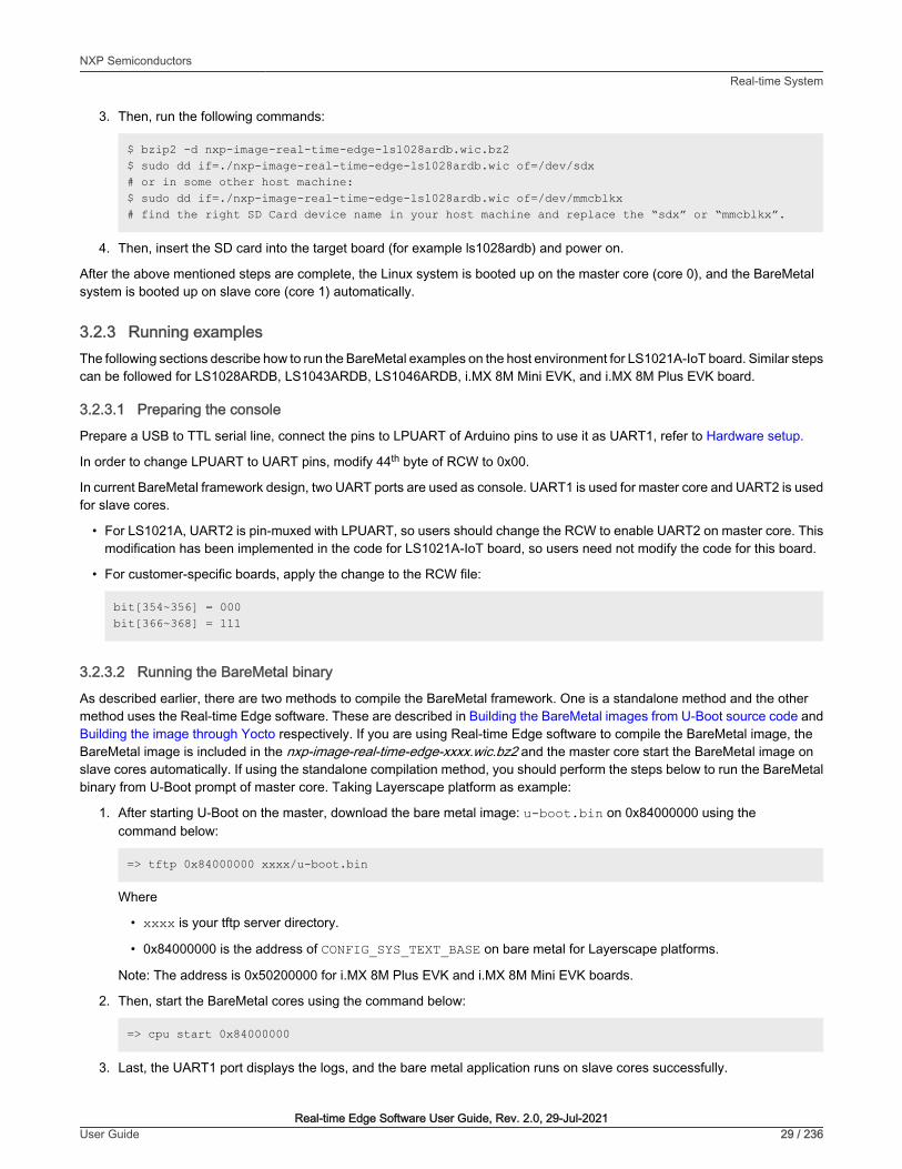
3.2.3 Running examplesThe following sections describe how to run the BareMetal examples on the host environment for LS1021A-IoT board. Similar stepscan be followed for LS1028ARDB, LS1043ARDB, LS1046ARDB, i.MX 8M Mini EVK, and i.MX 8M Plus EVK board.
3.2.3.1 Preparing the console
Prepare a USB to TTL serial line, connect the pins to LPUART of Arduino pins to use it as UART1, refer to Hardware setup.
In order to change LPUART to UART pins, modify 44th byte of RCW to 0x00.
In current BareMetal framework design, two UART ports are used as console. UART1 is used for master core and UART2 is usedfor slave cores.
• For LS1021A, UART2 is pin-muxed with LPUART, so users should change the RCW to enable UART2 on master core. Thismodification has been implemented in the code for LS1021A-IoT board, so users need not modify the code for this board.
• For customer-specific boards, apply the change to the RCW file:
bit[354~356] = 000bit[366~368] = 111
3.2.3.2 Running the BareMetal binary
As described earlier, there are two methods to compile the BareMetal framework. One is a standalone method and the othermethod uses the Real-time Edge software. These are described in Building the BareMetal images from U-Boot source code andBuilding the image through Yocto respectively. If you are using Real-time Edge software to compile the BareMetal image, theBareMetal image is included in the nxp-image-real-time-edge-xxxx.wic.bz2 and the master core start the BareMetal image onslave cores automatically. If using the standalone compilation method, you should perform the steps below to run the BareMetalbinary from U-Boot prompt of master core. Taking Layerscape platform as example:
1. After starting U-Boot on the master, download the bare metal image: u-boot.bin on 0x84000000 using thecommand below:
=> tftp 0x84000000 xxxx/u-boot.bin
Where
• xxxx is your tftp server directory.
• 0x84000000 is the address of CONFIG_SYS_TEXT_BASE on bare metal for Layerscape platforms.
Note: The address is 0x50200000 for i.MX 8M Plus EVK and i.MX 8M Mini EVK boards.
2. Then, start the BareMetal cores using the command below:
=> cpu start 0x84000000
3. Last, the UART1 port displays the logs, and the bare metal application runs on slave cores successfully.
NXP SemiconductorsReal-time System
Real-time Edge Software User Guide, Rev. 2.0, 29-Jul-2021User Guide 29 / 236

The figure below displays a sample output log.
Figure 5. BareMetal output logs
3.2.4 Development based on BareMetal frameworkThis chapter describes how to develop customer-specific application based on BareMetal framework.
3.2.4.1 Developing the BareMetal application
The directory “app” in the U-boot repository includes the test cases for testing the I2C, GPIO and IRQ init features. You can writeactual applications and store them in this directory.
3.2.4.2 Example software
This section describes how to analyze a GPIO sample code and use it to write the actual application.
3.2.4.2.1 Main file app.c
The file <industry-Uboot path>/app/app.c, is the main entrance for all applications. Users can modify the app.c file to addtheir applications.
• If using standalone method to build the BareMetal image as described in Building the BareMetal images from U-Boot sourcecode, just change the directory to industry-Uboot path to check the app.c file.
• If using Real-time Edge software to compile the BareMetal binary, you should change to the building directory to check theapp.c file.
The following is a sample code of the file app.c that shows how to add the example test cases of I2C, IRQ, and GPIO.
void core1_main(void){ test_i2c(); test_irq_init(); test_gpio();
NXP SemiconductorsReal-time System
Real-time Edge Software User Guide, Rev. 2.0, 29-Jul-2021User Guide 30 / 236

return;}
3.2.4.2.2 Common header files
There are some common APIs provided by BareMetal. The table below describes the header files that include the APIs.
Table 9. Common header file description
Header file Description
asm/io.h Read/Write IO APIs.
For example, __raw_readb, __raw_writeb, out_be32, and in_be32.
linux/string.h APIs for manipulating strings.
For example, strlen, strcpy, and strcmp.
linux/delay.h APIs used for small pauses.
For example, udelay and mdelay.
linux/types.h APIs specifying common types.
For example, __u32 and __u64.
common.h Common APIs.
For example, printf and puts.
3.2.4.2.3 GPIO file
The file uboot/app/test_gpio.c is one example to test the GPIO feature, and shows how to write a GPIO application.
Here is an example for the ls1021aiot board:
On ls1021aiot board, first you need the GPIO header file, asm-generic/gpio.h, which includes all interfaces for the GPIO.Then, configure GPIO25 to OUT direction, and configure GPIO24 to IN direction. Last, by writing the value 1 or 0 to GPIO25, youcan receive the same value from GPIO24.
The table below shows the APIs used in the file test_gpio.c example.
Table 10. GPIO APIs and their description
Function declaration Description
gpio_request (ngpio, label) Requests GPIO.
• ngpio - The GPIO number, such as 25, that is for GPIO25.
• label – the name of GPIOI request.
Returns 0 if OK, -1 on Error.
gpio_direction_output(ngpio, value)
Configures the direction of GPIO to OUT and writes the value to it.
• ngpio - The GPIO number, such as 25,that is, for GPIO25.
• value – the value written to this GPIO.
Returns 0 if Low, 1 if High, -1 on Error.
Table continues on the next page...
NXP SemiconductorsReal-time System
Real-time Edge Software User Guide, Rev. 2.0, 29-Jul-2021User Guide 31 / 236

Table 10. GPIO APIs and their description (continued)
Function declaration Description
gpio_direction_input(ngpio);
Configures the direction of GPIO to IN.
ngpio - The GPIO number, such as 24, that is for GPIO24;
Returns 0 if OK, -1 on Error.
gpio_get_value (ngpio) Reads the value.
• ngpio - The GPIO number, such as 24, that is for GPIO24;
Returns 0 if Low, 1 if High, -1 on Error.
gpio_free (ngpio) Frees the GPIO just requested.
• ngpio - The GPIO number, such as 24, that is for GPIO24;
Returns 0 if OK, -1 on error.
3.2.4.2.4 I2C file
The file uboot/app/test_i2c.c can be used as an example to test the I2C feature and shows how to write an I2C application.
On ls1021aiot board, include the I2C header file, i2c.h, which contains all interfaces for I2C. Then, read a fixed data from offset0 of Audio codec device (0x2A). If the data is 0xa0, the message, [ok]I2C test ok, is displayed on the console.
On ls1043ardb board, read a fixed data from offset 0 of INA220 device(0x40). If the data is 0x39, a message, [ok]I2C test okis displayed on the console.
The table below shows the APIs used in the sample file, test_i2c.c.
Table 11. I2C APIs and their description
Function declaration Description
int i2c_set_bus_num (unsignedint bus)
Sets the I2C bus.
bus- bus index, zero based
Returns 0 if OK, -1 on error.
int i2c_read (uint8_t chip, unsignedint addr, int alen, uint8_t *buffer,int len)
Read data from I2C device chip.
• chip - I2C chip address, range 0..127
• addr - Memory (register) address within the chip
• alen - Number of bytes to use for address (typically 1, 2 for larger memories,0 for register type devices with only one register)
• buffer - Where to read/write the data
• len - How many bytes to read/write
Returns 0 if OK, not 0 on error.
int i2c_write (uint8_t chip,unsigned int addr, int alen, uint8_t*buffer, int len)
Writes data to I2C device chip.
• chip - I2C chip address, range 0..127
• addr - Memory (register) address within the chip
Table continues on the next page...
NXP SemiconductorsReal-time System
Real-time Edge Software User Guide, Rev. 2.0, 29-Jul-2021User Guide 32 / 236

Table 11. I2C APIs and their description (continued)
Function declaration Description
• alen - Number of bytes to use for address (typically 1, 2 for larger memories,0 for register type devices with only one register)
• buffer - Where to read/write the data
• len - How many bytes to read/write
Returns 0 if OK, not 0 on error.
3.2.4.2.5 IRQ file
The file, uboot/app/test_irq_init.c is an example to test the IRQ and IPI (Inter-Processor Interrupts) feature, and shows how to writean IRQ application. The process is described in brief below.
The file asm/interrupt-gic.h, is the header file of IRQ, and includes all its interfaces. Then, register an IRQ function for SGI 0.After setting an SGI signal, the CPU gets this IRQ and runs the IRQ function. Then, register a hardware interrupt function to showhow to use the external hardware interrupt.
SGI IRQ is used for inter-processor interrupts, and it can only be used between bare metal cores. In case you want to communicatebetween BareMetal core and Linux core, refer to ICC module . SGI IRQ id is 0-15. The SGI IRQ id '8' is reserved for ICC.
For i.MX 8M Mini EVK and i.MX 8M Plus EVK board, SGI IRQ id is 9.
NOTE
The table below shows the APIs used in the sample file, test_irq_init.c.
Table 12. IRQ APIs and their description
Return type API name (parameterlist)
Description
void gic_irq_register(int irq_num, void(*irq_handle)(int))
Registers an IRQ function.
• irq_num- IRQ id, 0-15 for SGI, 16-31 for PPI, 32-1019 for SPI
• irq_handle – IRQ function
void gic_set_sgi (intcore_mask, u32 hw_irq)
Sets a SGI IRQ signal.
• core_mask – target core mask
• hw_irq – IRQ id
void gic_set_target(u32 core_mask, unsignedlong hw_irq)
Sets the target core for hw IRQ.
• core_mask – target core mask
• hw_irq – IRQ id
void gic_set_type (unsignedlong hw_irq)
Sets the type for hardware IRQ to identify whether the corresponding interrupt is edge-triggered or level-sensitive.
• hw_irq – IRQ id
3.2.4.2.6 QSPI file
The file uboot/app/test_qspi.c provides an example that can be used to test the QSPI feature. The below steps show howto write a QSPI application:
NXP SemiconductorsReal-time System
Real-time Edge Software User Guide, Rev. 2.0, 29-Jul-2021User Guide 33 / 236

1. First, locate the QSPI header files spi_flash.h and spi.h, which include all interfaces for QSPI.
2. Then, initialize the QSPI flash. Subsequently, erase the corresponding flash area and confirm that the erase operationis successful.
3. Now, read or write to the flash with an offset of 0x3f00000 and size of 0x40000.
The table below shows the APIs used in the file test_qsip.c example.
Table 13. QSPI APIs
API name (type) Description
spi_find_bus_and_cs(bus,cs,&bus_dev, &new)
The API finds if a SPI device already exists.
• “bus” - bus index, zero based.
• “cs” – the value to chip select mode.
• “bus_dev” - If the bus is found.
• “new” – If the device is found.
Returns 0 if OK, -ENODEV on error.
spi_flash_probe_bus_cs(bus, cs,speed, mode, &new)
Initializes the SPI flash device.
• “bus” - bus index, zero based.
• “cs” – the value to Chip Select mode.
• “speed” – SPI flash speed, can use 0 or CONFIG_SF_DEFAULT_SPEED.
• “mode” –SPI flash mode, can use 0 or CONFIG_SF_DEFAULT_MODE.
• “new” – If the device is initialized.
Returns 0 if OK, -ENODEV on error.
dev_get_uclass_priv(new) Gets the SPI flash.
• “new” - The device being initialized.
Returns flash if OK , NULL on error.
spi_flash_erase(flash, offset, size) Erases the specified location and length of the flash content, erases the contentof all.
• “flash” - Flash is being initialized.
• “offset” – Flash offset address.
• “size” - Erase the length of the data.
Returns 0 if OK, !0 on error.
spi_flash_read(flash, offset,len, vbuf)
Reads flash data to memory.
• “flash” - The flash being initialized.
• “offset” – Flash offset address.
• “len” - Read the length of the data.
• "vbug" - the buffer to store the data read
Returns 0 if OK, !0 on error.
Table continues on the next page...
NXP SemiconductorsReal-time System
Real-time Edge Software User Guide, Rev. 2.0, 29-Jul-2021User Guide 34 / 236

Table 13. QSPI APIs (continued)
API name (type) Description
spi_flash_write(flash, offset,len, buf)
Writes memory data to flash.
• “flash” - The flash being initialized.
• “offset” – Flash offset address.
• “len” - Write the length of the data.
• "buf" - the buffer to store the data write
Returns 0 if OK, !0 on error.
3.2.4.2.7 IFC
Both LS1043ARDB and LS1046ARDB have IFC controller. However, LS1043ARDB supports both NOR flash and NAND flash,whereas LS1046ARDB supports only NAND flash.
NOR and NAND flash messages are displayed while booting BareMetal cores, as shown below:
1:NAND: 512 MiB1:Flash: 128 MiB
or (LS1046ARDB)
1:NAND: 512 MiB
There is no example code to test it, but we can use a few commands to verify these features.
For LS1043ARDB NOR Flash (the map memory address is 0x60000000), below command can be used to verify it:
=> md 0x600000001:60000000: 55aa55aa 0001ee01 10001008 0000000a .U.U............1:60000010: 00000000 00000000 02005514 12400080 [email protected]:60000020: 005002e0 002000c1 00000000 00000000 ..P... .........1:60000030: 00000000 00880300 00000000 01110000 ................1:60000040: 96000000 01000000 78015709 10e00000 .........W.x....1:60000050: 00001809 08000000 18045709 9e000000 .........W......1:60000060: 1c045709 9e000000 20045709 9e000000 .W.......W. ....1:60000070: 00065709 00000000 04065709 00001060 .W.......W..`...1:60000080: c000ee09 00440000 58015709 00220000 ......D..W.X..".1:60000090: 40800089 01000000 40006108 f56b710a [email protected][email protected]:600000a0: ffffffff ffffffff ffffffff ffffffff ................
For NAND flash on LS1043ARDB and LS1046ARDB, "nand" command can be used to verify it (nand erase, nand read, nand write,and so on.):
=> nand info
1:Device 0: nand0, sector size 128 KiB1: Page size 2048 b1: OOB size 64 b1: Erase size 131072 b1: subpagesize 2048 b
NXP SemiconductorsReal-time System
Real-time Edge Software User Guide, Rev. 2.0, 29-Jul-2021User Guide 35 / 236

1: options 0x000042001: bbt options 0x00028000
=> nand1:nand - NAND sub-system
1:Usage:nand info - show available NAND devicesnand device [dev] - show or set current devicenand read - addr off|partition sizenand write - addr off|partition size read/write 'size' bytes starting at offset 'off' to/from memory address 'addr', skipping bad blocks.nand read.raw - addr off|partition [count]nand write.raw[.noverify] - addr off|partition [count] Use read.raw/write.raw to avoid ECC and access the flash as-is.nand erase[.spread] [clean] off size - erase 'size' bytes from offset 'off' With '.spread', erase enough for given file size, otherwise, 'size' includes skipped bad blocks.nand erase.part [clean] partition - erase entire mtd partition'nand erase.chip [clean] - erase entire chip'nand bad - show bad blocksnand dump[.oob] off - dump pagenand scrub [-y] off size | scrub.part partition | scrub.chip really clean NAND erasing bad blocks (UNSAFE)nand markbad off [...] - mark bad block(s) at offset (UNSAFE)nand biterr off - make a bit error at offset
3.2.4.2.8 Ethernet
The file uboot/app/test_net.c provides an example to test the Ethernet feature and shows how to write a net application forusing this feature.
Here is an example for the LS1043ARDB (or LS1046ARDB) board.
1. Connect one Ethernet port of LS1043ARDB board to one host machine using Ethernet cable.
• (For LS1046ARDB, the default ethact is FM1@DTSEC5. Network cable should be connected to SGMII1 port.
• For LS1043ARDB, the default ethact is FM1@DTSEC3. Network cable should be connected to RGMII1 port.
2. Configure the IP address of the host machine as 192.168.1.2.
3. Power up the LS1043ARDB board. If the network is connected, the message host 192.168.1.2 is alive is displayedon the console.
4. The IP addresses of the board and host machine are defined in the file test_net.c. In this file, modify the IP address ofLS1043ARDB board using variable ipaddr and change the IP address of host machine using variable ping_ip.
The table below lists the Net APIs and their description.
Table 14. Net APIs and their description
API name (type) Description
void net_init (void) Initializes the network
int net_loop (enum proto_t protocol) Main network processing loop.
• enum proto_t protocol - protocol type
Table continues on the next page...
NXP SemiconductorsReal-time System
Real-time Edge Software User Guide, Rev. 2.0, 29-Jul-2021User Guide 36 / 236

Table 14. Net APIs and their description (continued)
API name (type) Description
int eth_receive (void *packet,int length)
Reads data from NIC device chip.
• void *packet
• length - Network packet length
Returns length
int eth_send (void *packet,int length)
Writes data to NIC device chip.
• packet - pointer to the packet is sent
• length - Network packet length
Returns length.
3.2.4.2.9 USB file
The file uboot/app/test_usb.c provides an example that can be used to test the USB features. The steps below show how towrite a USB application:
1. Connect a USB disk to the USB port.
2. Include the header file, usb.h, which includes all APIs for USB.
3. Initialize the USB device using the usb_init API.
4. Scan the USB storage device on the USB bus using the usb_stor_scanAPI.
5. Get the device number using the blk_get_devnum_by_type API.
6. Read data from the USB disk using the blk_dread API.
7. Write data to the USB disk using the blk_dwrite API.
The table below shows the APIs used in the file test_usb.c example:
Table 15. USB APIs and their description
API name (type) Description
int usb_init(void) Initializes the USB controller.
int usb_stop(void) Stops the USB controller.
int usb_stor_scan(int mode) Scans the USB and reports device information to the user ifmode = 1
• Mode – if mode = 1, the information is returned to user.
Returns
• the current device, or
• -1 (if device not found).
struct blk_desc *blk_get_devnum_by_type(enumif_type if_type, int devnum)
Get a block device by type and number.
• If_type – Block device type
• devnum - device number
Returns
Table continues on the next page...
NXP SemiconductorsReal-time System
Real-time Edge Software User Guide, Rev. 2.0, 29-Jul-2021User Guide 37 / 236

Table 15. USB APIs and their description (continued)
• Points to block device descriptor, or
• NULL (if not found).
unsigned long blk_dread(struct blk_desc*block_dev, lbaint_t start, lbaint_t blkcnt, void*buffer);
Reads data from USB device.
• block_dev – block device descripter
• start – start block
• blkcnt – block number
• buffer – buffer to store the data
Returns the block number from which, data is read.
unsigned long blk_dwrite(struct blk_desc*block_dev, lbaint_t start, lbaint_t blkcnt, constvoid *buffer);
Writes data to USB device.
• block_dev – block device descripter
• start – start block
• blkcnt – block number
• buffer – buffer to store the data
Returns the block number to which data is written.
3.2.4.2.10 PCIe file
The file app/test_pcie.c provides a sample code to test PCIe and network card (such as e1000) features. The steps below showhow to write a PCIe and net application:
1. Insert a PCIe network card (such as e1000) into PCIe2, or PCIe3 slot (if it exists).
2. Configure the IP address of the host machine to 192.168.1.2.
3. Include the files include/pci.h and include/ netdev.h.
4. Initialize the PCIe controller using the pci_init API.
5. Get uclass device by its name using the uclass_get_device_by_seq API.
6. Initialize the PCIe network device using the pci_eth_init API.
7. Begin pinging the host machine using the net_loop API.
The table below shows the APIs used in the file test_pcie.c example.
Table 16. PCIe APIs and their description
API name (type) Description
void pci_init(void) Initializes the PCIe controller. Does not return a value.
int uclass_get_device_by_seq(enumuclass_id id, int seq, structudevice **devp)
Gets the uclass device based on an ID and sequence:
• id – uclass ID
• seq – sequence
• devp – Pointer to device
Returns:
Table continues on the next page...
NXP SemiconductorsReal-time System
Real-time Edge Software User Guide, Rev. 2.0, 29-Jul-2021User Guide 38 / 236

Table 16. PCIe APIs and their description (continued)
• 0 if Ok.
• Negative value on error.
static inline int pci_eth_init(bd_t*bis)
Initializes network card on the PCIe bus.
• Bis – struct containing variables accessed by shared code
Returns the number of network cards.
int net_loop (enum proto_t protocol) Main network processing loop.
• enum proto_t protocol - protocol type
Returns:
• 0 if Ok.
• Negative value on error.
3.2.4.2.11 CAN file
The file app/test_flexcan.c provides a sample test case to test flexCAN and CANopen features. The following steps show thedesign process:
1. Register the receive interruption function for flexCAN.
2. Register an overflow interruption function for flextimer.
3. Initialize a list of callback functions.
4. Set the node ID of this node.
The table below shows the APIs used in the file test_flexcan.c example.
Table 17. CAN APIs and their description
API name (type) Description
void test_flexcan(void) It is the test code entry for flexCAN.
void flexcan_rx_irq(structcan_module *canx)
FlexCAN receive interruption function.
• canx – flexCAN interface.
void flexcan_receive(structcan_module *canx, structcan_frame *cf)
FlexCAN receives CAN data frame.
• canx – FlexCAN interface.
• cf – CAN message.
UNS8 setState(CO_Data* d,e_nodeState newState)
Sets node state
• d – object dictionary
• newState – The state that requires to be set.
Returns:
• 0 if Ok,
• > 0 on error.
void canDispatch(CO_Data* d,Message *m)
CANopen handles data frames that CAN receives:
Table continues on the next page...
NXP SemiconductorsReal-time System
Real-time Edge Software User Guide, Rev. 2.0, 29-Jul-2021User Guide 39 / 236

Table 17. CAN APIs and their description (continued)
• d – object dictionary.
• m – Received CAN message.
int flexcan_send(structcan_module *canx, structcan_frame *cf)
FlexCAN interface sends CAN message:
• canx – FlexCAN interface.
• cf – CAN message.
void flextimer_overflow_irq(void) Flextimer overflow interruption handler function.
void timerForCan(void) CANopen virtual clock. Call this function per 100 μs.
• The following log shows the CANopen slave node state:
=> flexcan error: 0x42242! Note: slave node entry into the stop mode!Note: slave node initialization is complete!Note: slave node entry into the preOperation mode!Note: slave node entry into the operation mode!Note: slave node initialization is complete! Note: slave node entry into the preOperation mode!Note: slave node entry into the operation mode!
3.2.4.2.12 ENETC file
The file app/test_net.c provides an example to test ENETC Ethernet feature and shows how to write a net application for usingthis feature. This is a special case of using Net APIs.
The file test_net for ENETC is only an example for the LS1028ARDB board (CONFIG_ENETC_COREID_SET enabled).
1. Connect ENETC port of LS1028ARDB board to one host machine using Ethernet cable.
2. Configure the IP address of the host machine as 192.168.1.2.
3. Power up the LS1028ARDB board. If the network is connected, the message host 192.168.1.2 is alive is displayedon the console.
4. The IP addresses of the board and host machines are defined in the file test_net.c. In this file, modify the IP addressof LS1028ARDB board using variable ipaddr and change the IP address of host machine using variable ping_ip.
The table below lists the Net APIs for ENETC and their description, refer to section 4.2.7 for other Net APIs.
Table 18. ENETC APIs and their description
API name (type) Description
void pci_init(void) Initializes the PCIe controller. Does not return a value.
void eth_initialize(void) Initializes the Ethernet.
3.2.4.2.13 SAI file
The audio feature needs SAI module and codec drivers. The following sections provide an introduction to SAI module, audio codec(SGTL5000), details of how to integrate audio with BareMetal and running an audio application on BareMetal.
NXP SemiconductorsReal-time System
Real-time Edge Software User Guide, Rev. 2.0, 29-Jul-2021User Guide 40 / 236

3.2.4.2.13.1 Synchronous Audio Interface (SAI)
The LS1028A integrates six SAI modules, but only SAI4 is used by LS1028ARDB board. The synchronous audio interface(SAI) supports full duplex serial interfaces with frame synchronization. The bit clock and frame sync of SAI are both generatedexternally (SGTL5000).
• Transmitter with independent bit clock and frame sync supporting 1 data line
• Receiver with independent bit clock and frame sync supporting 1 data line
• Maximum Frame Size of 32 words
• Word size of between 8-bits and 32-bits
• Word size configured separately for first word and remaining words in frame
• Asynchronous 32 × 32-bit FIFO for each transmit and receive channel
• Supports graceful restart after FIFO error
Figure SAI block diagram
3.2.4.2.13.2 Audio codec (SGTL5000)
The SGTL5000 is a low power stereo codec with headphone amplifier from NXP. It is designed to provide a complete audiosolution for products needing LINEIN, MIC_IN, LINEOUT, headphone-out, and digital I/O. It allows an 8.0 MHz to 27 MHz systemclock as input. The codec supports 8.0 kHz, 11.025 kHz, 12 kHz, 16 kHz, 22.05 kHz, 24 kHz, 32 kHz, 44.1 kHz, 48 kHz, and 96kHz sampling frequencies. The LS1028ARDB board provides a 25 MHz crystal oscillator to the SGTL5000.
The SGTL5000 provides two interfaces (I2C and SPI) to setup registers. The LS1028ARDB board uses I2C interface.
NXP SemiconductorsReal-time System
Real-time Edge Software User Guide, Rev. 2.0, 29-Jul-2021User Guide 41 / 236

Figure 6. System block diagram, signal flow, and gain
3.2.4.2.13.3 Digital interface formats
The SGTL5000 provides five common digital interface formats. The SAI and SGTL5000 digital interface formats must bethe same.
• I2S Format (n = bit length)
• Left Justified Format (n = bit length)
NXP SemiconductorsReal-time System
Real-time Edge Software User Guide, Rev. 2.0, 29-Jul-2021User Guide 42 / 236
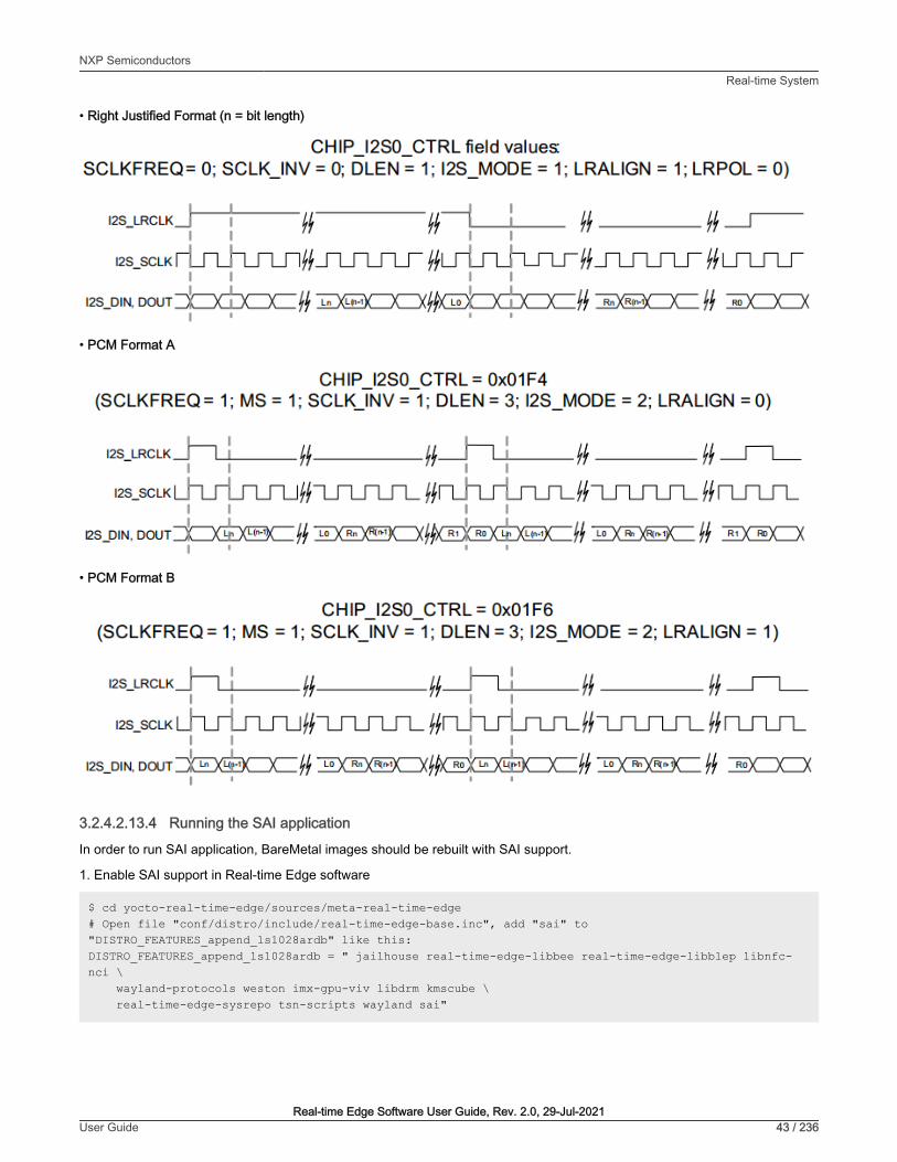
• Right Justified Format (n = bit length)
• PCM Format A
• PCM Format B
3.2.4.2.13.4 Running the SAI application
In order to run SAI application, BareMetal images should be rebuilt with SAI support.
1. Enable SAI support in Real-time Edge software
$ cd yocto-real-time-edge/sources/meta-real-time-edge # Open file "conf/distro/include/real-time-edge-base.inc", add "sai" to "DISTRO_FEATURES_append_ls1028ardb" like this: DISTRO_FEATURES_append_ls1028ardb = " jailhouse real-time-edge-libbee real-time-edge-libblep libnfc-nci \ wayland-protocols weston imx-gpu-viv libdrm kmscube \ real-time-edge-sysrepo tsn-scripts wayland sai"
NXP SemiconductorsReal-time System
Real-time Edge Software User Guide, Rev. 2.0, 29-Jul-2021User Guide 43 / 236
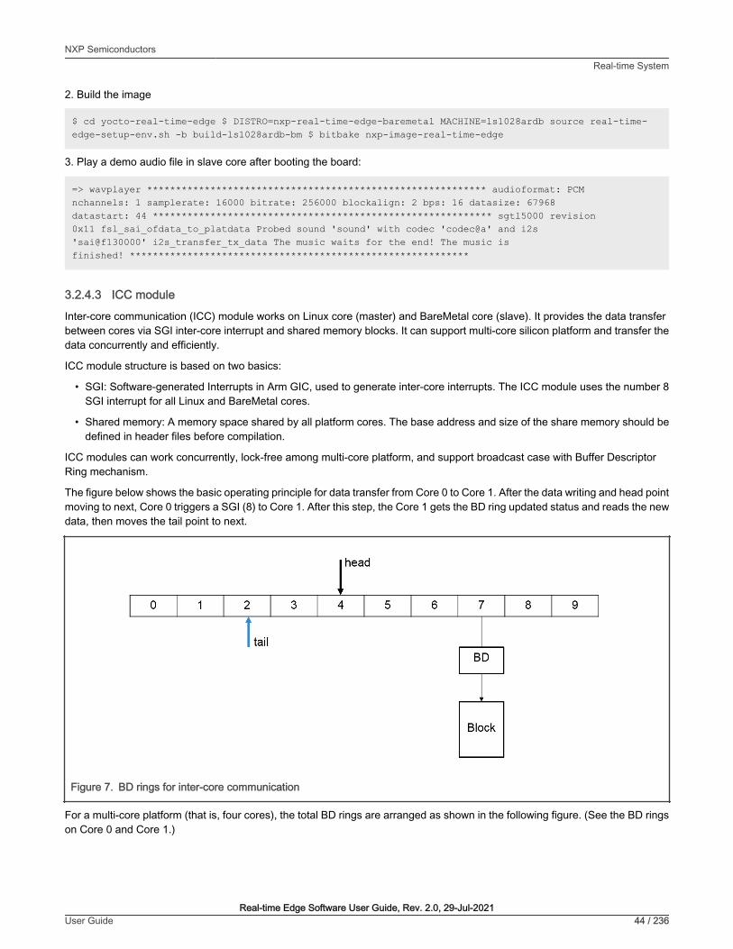
2. Build the image
$ cd yocto-real-time-edge $ DISTRO=nxp-real-time-edge-baremetal MACHINE=ls1028ardb source real-time-edge-setup-env.sh -b build-ls1028ardb-bm $ bitbake nxp-image-real-time-edge
3. Play a demo audio file in slave core after booting the board:
=> wavplayer *********************************************************** audioformat: PCM nchannels: 1 samplerate: 16000 bitrate: 256000 blockalign: 2 bps: 16 datasize: 67968 datastart: 44 *********************************************************** sgtl5000 revision 0x11 fsl_sai_ofdata_to_platdata Probed sound 'sound' with codec 'codec@a' and i2s 'sai@f130000' i2s_transfer_tx_data The music waits for the end! The music is finished! ***********************************************************
3.2.4.3 ICC module
Inter-core communication (ICC) module works on Linux core (master) and BareMetal core (slave). It provides the data transferbetween cores via SGI inter-core interrupt and shared memory blocks. It can support multi-core silicon platform and transfer thedata concurrently and efficiently.
ICC module structure is based on two basics:
• SGI: Software-generated Interrupts in Arm GIC, used to generate inter-core interrupts. The ICC module uses the number 8SGI interrupt for all Linux and BareMetal cores.
• Shared memory: A memory space shared by all platform cores. The base address and size of the share memory should bedefined in header files before compilation.
ICC modules can work concurrently, lock-free among multi-core platform, and support broadcast case with Buffer DescriptorRing mechanism.
The figure below shows the basic operating principle for data transfer from Core 0 to Core 1. After the data writing and head pointmoving to next, Core 0 triggers a SGI (8) to Core 1. After this step, the Core 1 gets the BD ring updated status and reads the newdata, then moves the tail point to next.
Figure 7. BD rings for inter-core communication
For a multi-core platform (that is, four cores), the total BD rings are arranged as shown in the following figure. (See the BD ringson Core 0 and Core 1.)
NXP SemiconductorsReal-time System
Real-time Edge Software User Guide, Rev. 2.0, 29-Jul-2021User Guide 44 / 236

Figure 8. BD rings for multi-core platform
All the ICC ring structures, BD structures and blocks for data are in the shared memory. A four-core platform ICC module wouldmap the shared memory as shown in the figure below.
Figure 9. ICC shared memory map for the four-core platform
Generally, Core 0 runs Linux as master core, other cores run BareMetal as slaves. They obtain the same size of share memoryto structure the rings and BDs, and split the blocks space with 4k unit for each block. The reserved space at the top of the sharememory is out of the ICC module and for the custom usage.
For LS1021A platform with two cores, the share memory map is defined as:
• The total shared memory size is 256 MB.
• The reserved space for custom usage is 16 MB at the top of the share memory space.
• Core 0 runs Linux as master core, the share memory size for ICC is 120 MB, in which the ring and BD structure space is 2M, and the block space for data is 118 MB with 4K for each block.
• Core 1 runs BareMetal as slave core, the share memory size for ICC is 120 MB, in which the ring and BD structure space is2M, and the block space for data is 118 MB with 4K for each block.
NXP SemiconductorsReal-time System
Real-time Edge Software User Guide, Rev. 2.0, 29-Jul-2021User Guide 45 / 236

The ICC module includes two parts of the code:
• ICC code for Linux user space, works for data transfer between master core and slave cores. The code is integratedinto the Real-time Edge software and named real-time-edge-icc. After the compilation, the icc binary is put into theLinux filesystem.
• ICC code for BareMetal, runs on every slave core, works for data transfer between BareMetal cores and master core.
The ICC code for Linux user space in repos: https://github.com/real-time-edge-sw/real-time-edge-icc.git
├── icc-main.c --- the example case commands
├── inter-core-comm.c
├── inter-core-comm.h --- include the header file to use ICC module
└── Makefile
The ICC code for BareMetal in BareMetal directory:
baremetal/
├── arch/arm/lib/inter-core-comm.c
├── arch/arm/include/asm/inter-core-comm.h --- includes the header file to use ICC module
└── cmd/icc.c --- the example case commands
The APIs ICC are exported out for usage in both Linux user space and BareMetal code.
Table 19. ICC APIs
APIs Description
unsigned longicc_ring_state(int coreid)
Checks the ring and block state.
Returns:
• 0 - if empty.
• !0 - the working block address currently.
Unsignedlong icc_block_request(void)
Requests a block, which is ICC_BLOCK_UNIT_SIZE size.
Returns:
• 0 - failed.
• !0 - block address can be used.
void icc_block_free(unsignedlong block)
Frees a block requested.
Be careful if the destination cores are working on this block.
int icc_irq_register(int src_coreid,void (*irq_handle)(int, unsignedlong, unsigned int))
Registers ICC callback handler for received data.
Returns:
• 0 - on success
• -1 - if failed.
int icc_set_block(int core_mask,unsigned int byte_count, unsignedlong block)
Sends the data in the block to a core or multi-core.
This triggers the SGI interrupt.
Returns:
Table continues on the next page...
NXP SemiconductorsReal-time System
Real-time Edge Software User Guide, Rev. 2.0, 29-Jul-2021User Guide 46 / 236

Table 19. ICC APIs (continued)
APIs Description
• 0 - on success
• -1 - if failed.
void icc_show(void) Shows the ICC basic information.
int icc_init(void) Initializes the ICC module.
3.2.4.3.1 ICC examples
This section provides example commands for use cases in both Linux user space and BareMetal code. They can be used to checkand verify the ICC module conveniently.
1. In Linux user space, use the command icc to display the supported cases.
[root@LS1046ARDB ~] # iccicc show - Shows all icc rings status at this coreicc perf <core_mask> <counts> - ICC performance to cores <core_mask> with <counts> bytesicc send <core_mask> <data> <counts> - Sends <counts> <data> to cores <core_mask>icc irq <core_mask> <irq> - Sends SGI <irq> ID[0 - 15] to <core_mask>icc read <addr> <counts> - Reads <counts> 32bit register from <addr>icc write <addr> <data> - Writes <data> to a register <addr>
Likewise, in BareMetal system, use the command icc to view the supported cases.
=> icc1:icc - Inter-core communication via SGI interrupt
1:Usage:icc show - Show all icc rings status at this coreicc perf <core_mask> <counts> - ICC performance to cores <core_mask> with <counts> bytesicc send <core_mask> <data> <counts> - Send <counts> <data> to cores <core_mask>icc irq <core_mask> <irq> - Send SGI <irq> ID[0 - 15] to <core_mask>
2. The ICC module command examples on LS1046ARDB with Linux (Core 0) + BareMetal (Core 1, 2, 3) system:
Run icc send 0x2 0x55 128 to send 128 bytes data 0x55 to core 1.
[root@LS1046ARDB ~] # icc send 0x2 0x55 128gic_base: 0xffffa033f000, share_base: 0xffff9133f000, share_phy: 0xd0000000, block_phy: 0xd0200000
ICC send testing ...Target cores: 0x2, bytes: 128ICC send: 128 bytes to 0x2 cores success
all cores: reserved_share_memory_base: 0xdf000000; size: 16777216
mycoreid: 0; ICC_SGI: 8; share_memory_size: 62914560block_unit_size: 4096; block number: 14848; block_idx: 0
#ring 0 base: 0xffff9133f000; dest_core: 0; SGI: 8desc_num: 128; desc_base: 0xd00000c0; head: 0; tail: 0busy_counts: 0; interrupt_counts: 0
NXP SemiconductorsReal-time System
Real-time Edge Software User Guide, Rev. 2.0, 29-Jul-2021User Guide 47 / 236

#ring 1 base: 0xffff9133f030; dest_core: 1; SGI: 8desc_num: 128; desc_base: 0xd00008c0; head: 1; tail: 1busy_counts: 0; interrupt_counts: 1
#ring 2 base: 0xffff9133f060; dest_core: 2; SGI: 8desc_num: 128; desc_base: 0xd00010c0; head: 0; tail: 0busy_counts: 0; interrupt_counts: 0
#ring 3 base: 0xffff9133f090; dest_core: 3; SGI: 8desc_num: 128; desc_base: 0xd00018c0; head: 0; tail: 0busy_counts: 0; interrupt_counts: 0
At the same time, Core 1 prints the receival information.
=> 1:Get the ICC from core 0; block: 0xd0200000, bytes: 128, value: 0x55
3. ICC command run on BareMetal side
=> icc send 0x1 0xaa 1281:ICC send testing ...1:Target cores: 0x1, bytes: 1281:ICC send: 128 bytes to 0x1 cores success
1:all cores: reserved_share_memory_base: 0xdf000000; size: 16777216
1:mycoreid: 1; ICC_SGI: 8; share_memory_size: 629145601:block_unit_size: 4096; block number: 14848; block_idx: 0
1:#ring 0 base: 00000000d3c00000; dest_core: 0; SGI: 81:desc_num: 128; desc_base: 00000000d3c000c0; head: 1; tail: 11:busy_counts: 0; interrupt_counts: 1
1:#ring 1 base: 00000000d3c00030; dest_core: 1; SGI: 81:desc_num: 128; desc_base: 00000000d3c008c0; head: 0; tail: 01:busy_counts: 0; interrupt_counts: 0
1:#ring 2 base: 00000000d3c00060; dest_core: 2; SGI: 81:desc_num: 128; desc_base: 00000000d3c010c0; head: 0; tail: 01:busy_counts: 0; interrupt_counts: 0
1:#ring 3 base: 00000000d3c00090; dest_core: 3; SGI: 81:desc_num: 128; desc_base: 00000000d3c018c0; head: 0; tail: 01:busy_counts: 0; interrupt_counts: 0
Then, Core 0 side (Linux) will receive these data:
[root@LS1046ARDB ~] # [ 4247.733753] 000: Get the ICC from core 1; block: 0xd3e00000, bytes: 128, value: 0xaa
3.2.4.4 Hardware resource allocation
This section describes how to modify the hardware resource allocation depending on the application and used referencedesign board.
3.2.4.4.1 LS1021A-IoT board
3.2.4.4.1.1 Linux DTS
Remove cpu1 node on DTS, and remove all the devices that bare metal has used.
NXP SemiconductorsReal-time System
Real-time Edge Software User Guide, Rev. 2.0, 29-Jul-2021User Guide 48 / 236

3.2.4.4.1.2 Memory configuration
LS1021A-IoT board has a 1 GB size DDR. The DDR memory can be configured into three partitions: 512M for core0 (Linux), 256Mfor core1 (bare metal), and 256M for shared memory.
The configuration is in the path: include/configs/ls1021aiot_config.h.
#define CONFIG_SYS_DDR_SDRAM_SLAVE_SIZE (256 * 1024 * 1024)#define CONFIG_SYS_DDR_SDRAM_MASTER_SIZE (512 * 1024 * 1024)
Memory configuration must be consistent with the U-Boot configuration of core0.
NOTE
Modify “CONFIG_SYS_MALLOC_LEN” in the include/configs/ls1021aiot_config.h file to change the maximum size of malloc.
You can use functions included in malloc.h to allocate or free memory in your program. These functions are listed in thetable below.
Table 20. Description of memory APIs
API name (type) Description
void_t* malloc (size_t n) Allocates memory
• n – length of allocated chunk
• Returns a pointer to the newly allocated chunk
void free (void *ptr) Releases the chunk of memory pointed to by ptr (where ptr is a pointer to the chunk ofmemory)
The memory configuration for bare metal is shown in the figure below.
Figure 10. Memory configuration
NXP SemiconductorsReal-time System
Real-time Edge Software User Guide, Rev. 2.0, 29-Jul-2021User Guide 49 / 236

3.2.4.4.1.3 GPIO
LS1021A has four GPIO controllers. The configuration is defined in the file:arch/arm/dts/ls1021a-iot.dtsi. You can add a GPIOnode in the file ls1021a-iot.dtsi to assign a GPIO resource to different cores. Following is a sample code for adding a GPIO node.
&gpio2 { status = "okay";};
3.2.4.4.1.4 I2C
LS1021A has three I2C controllers. Configure the I2C bus on ls1021aiot_config.h using the commands below:
// include/configs/ls1021aiot_config.h:#define CONFIG_SYS_I2C_MXC_I2C1 /* enable I2C bus 1 */#define CONFIG_SYS_I2C_MXC_I2C2 /* enable I2C bus 2 */#define CONFIG_SYS_I2C_MXC_I2C3 /* enable I2C bus 3 */
3.2.4.4.1.5 Hardware interrupts
LS1021A has six IRQs as external IO signals connected to interrupt the controller. We can use these six IRQs on bare metal cores.The ids for these signals, IRQ0-IRQ5 are: 195, 196, 197, 199, 200, and 201.
GIC interrupt APIs are defined in the file, asm/interrupt-gic.h. The following example shows how to register ahardware interrupt:
//register HW interruptvoid gic_irq_register(int irq_num, void (*irq_handle)(int));void gic_set_target(u32 core_mask, unsigned long hw_irq);void gic_set_type(unsigned long hw_irq);
3.2.4.4.1.6 IFC
LS1021A-IoT board has no IFC device, but the LS1021A SoC has an IFC interface. Since IFC is multiplexed with QSPI, you shouldmodify the RCW to use the IFC interface, and add a configuration such as shown in the sample code provided below. Users canmodify the code to support IFC as per the actual scenario.
#define CONFIG_FSL_IFC#define CONFIG_SYS_CPLD_BASE 0x7fb00000#define CPLD_BASE_PHYS CONFIG_SYS_CPLD_BASE#define CONFIG_SYS_FPGA_CSPR_EXT (0x0)
#define CONFIG_SYS_FPGA_CSPR (CSPR_PHYS_ADDR(CPLD_BASE_PHYS) | \CSPR_PORT_SIZE_8 | \CSPR_MSEL_GPCM | \CSPR_V)
#define CONFIG_SYS_FPGA_AMASK IFC_AMASK(64 * 1024)#define CONFIG_SYS_FPGA_CSOR (CSOR_NOR_ADM_SHIFT(4) | \CSOR_NOR_NOR_MODE_AVD_NOR | \CSOR_NOR_TRHZ_80)
/* CPLD Timing parameters for IFC GPCM */#define CONFIG_SYS_FPGA_FTIM0 (FTIM0_GPCM_TACSE(0xf) | \FTIM0_GPCM_TEADC(0xf) | \FTIM0_GPCM_TEAHC(0xf))
NXP SemiconductorsReal-time System
Real-time Edge Software User Guide, Rev. 2.0, 29-Jul-2021User Guide 50 / 236

#define CONFIG_SYS_FPGA_FTIM1 (FTIM1_GPCM_TACO(0xff) | \FTIM1_GPCM_TRAD(0x3f))
#define CONFIG_SYS_FPGA_FTIM2 (FTIM2_GPCM_TCS(0xf) | \FTIM2_GPCM_TCH(0xf) | \FTIM2_GPCM_TWP(0xff))
#define CONFIG_SYS_FPGA_FTIM3 0x0#define CONFIG_SYS_CSPR1_EXT CONFIG_SYS_FPGA_CSPR_EXT#define CONFIG_SYS_CSPR1 CONFIG_SYS_FPGA_CSPR#define CONFIG_SYS_AMASK1 CONFIG_SYS_FPGA_AMASK#define CONFIG_SYS_CSOR1 CONFIG_SYS_FPGA_CSOR#define CONFIG_SYS_CS1_FTIM0 CONFIG_SYS_FPGA_FTIM0#define CONFIG_SYS_CS1_FTIM1 CONFIG_SYS_FPGA_FTIM1#define CONFIG_SYS_CS1_FTIM2 CONFIG_SYS_FPGA_FTIM2#define CONFIG_SYS_CS1_FTIM3 CONFIG_SYS_FPGA_FTIM3
3.2.4.4.1.7 USB
LS1021AIOT has a single DW3 USB controller, which is assigned to the second core, by default. Use the command makemenuconfig to re-configure the U-Boot to assign it to other cores.
ARM architecture --->[*] Enable baremetal[*] Enable USB for baremetal(1) USB0 is assigned to core1(1) USB Controller numbers
3.2.4.4.1.8 PCIe
LS1021AIOT has two PCIe controllers. By default, one is assigned to core0 and the other is assigned to core1. Use the makemenuconfig command to re-configure the U-Boot, in order to re-assign the cores.
ARM architecture --->[*] Enable baremetal[*] Enable PCIE for baremetal(0) PCIe1 is assigned to core0(1) PCIe2 is assigned to core1(2) PCIe Controller numbers
3.2.4.4.1.9 FlexCAN
Assigning CAN3 to BareMetal
In BareMetal, the port is allocated through the flexcan.c file. The flexcan.c path is industry-uboot/drivers/flexcan/flexcan.c. In this file, you should define the following variables:
struct can_bittiming_t flexcan3_bittiming = CAN_BITTIM_INIT(CAN_500K);
Note: You also should set the bit timing and baud rate (500K) of the CAN port.
struct can_ctrlmode_t flexcan3_ctrlmode = {.loopmode = 0, /* Indicates whether the loop mode is enabled */
NXP SemiconductorsReal-time System
Real-time Edge Software User Guide, Rev. 2.0, 29-Jul-2021User Guide 51 / 236

.listenonly = 0, /* Indicates whether the only-listen mode is enabled */
.samples = 0,
.err_report = 1,};struct can_init_t flexcan3 = {.canx = CAN3, /* Specify CAN port */.bt = &flexcan3_bittiming,.ctrlmode = &flexcan3_ctrlmode,.reg_ctrl_default = 0,.reg_esr = 0};
Optional Parameters
• CAN port
#define CAN3 (struct can_module *)CAN3_BASE)#define CAN4 (struct can_module *)CAN4_BASE)
• Baud rate
#define CAN_1000K 10#define CAN_500K 20#define CAN_250K 40#define CAN_200K 50#define CAN_125K 80#define CAN_100K 100#define CAN_50K 200#define CAN_20K 500#define CAN_10K 1000#define CAN_5K 2000
Use the command make menuconfig for configuring the FlexCAN setting for LS1021A reference design boards, as shown below: .
Device Drivers --->CAN support --->[*] Support for Freescale FLEXCAN based chips[*] Support for canfestival
3.2.4.4.2 LS1028ARDB board
This section describes the ENETC configuration setting for LS1028A reference design boards.
3.2.4.4.2.1 ENETC
LS1028ARDB has only one ENETC controller in use, which is assigned to core1 as the default setting. The controller can bereconfigured by using the command, make menuconfig.
See the following:
ARM architecture --->[*] Enable baremetal[*] Enable ENETC for baremetal (1) Enetc1 is assigned to core1 (1) ENETC Controller numbers
NXP SemiconductorsReal-time System
Real-time Edge Software User Guide, Rev. 2.0, 29-Jul-2021User Guide 52 / 236

3.2.4.4.2.2 I2CThis section describes how to configure the I2C bus on LS1028A reference design boards.
LS1028ARDB has eight I2C controllers, but only controller 0 is used for I2C devices (for example RTC, Thermal Monitor), andLinux (core 0) will use this controller for some features (for example RTC). Therefore, below codes is just used to demo how toenable I2C in BareMetal side.
Note: Operating the I2C devices in BareMetal side CAREFULLY.
#define CONFIG_SYS_I2C_MXC_I2C1 /* enable I2C bus 0 */#define CONFIG_SYS_I2C_MXC_I2C2 /* enable I2C bus 1 */#define CONFIG_SYS_I2C_MXC_I2C3 /* enable I2C bus 2 */#define CONFIG_SYS_I2C_MXC_I2C4 /* enable I2C bus 3 */
#define CONFIG_I2C_BUS_CORE_ID_SET#define CONFIG_SYS_I2C_MXC_I2C0_COREID 1
The CONFIG_SYS_I2C_MXC_I2C0_COREID defines the slave core that runs the I2C bus.
Because I2C is enabled with DM mode in BareMetal side, there is not automatic codes to test it. Follow below steps to readRTC (0x51 address, is on bus 2) in BareMetal side :
=> i2c busBus 0: i2c@2000000 (active 0) 77: i2c-mux@77, offset len 1, flags 0 57: generic_57, offset len 1, flags 0Bus 1: i2c@2000000->i2c-mux@77->i2c@1Bus 2: i2c@2000000->i2c-mux@77->i2c@3 51: rtc@51, offset len 1, flags 0Bus 3: i2c@2010000Bus 4: i2c@2020000Bus 5: i2c@2030000Bus 6: i2c@2040000Bus 7: i2c@2050000Bus 8: i2c@2060000Bus 9: i2c@2070000=> i2c md 0x51 0Error reading the chip: -121=> i2c dev 2Setting bus to 2=> i2c md 0x51 00000: 04 00 36 03 12 15 02 12 20 80 80 80 80 80 00 c2 ..6..... .......
3.2.4.4.2.3 SAI
LS1028ARDB has only one SAI module in use, which is assigned to core1 as the default setting. The SAI module can bereconfigured by using the command, make menuconfig.
See the following:
Command line interface ---> Misc commands ---> [*] wavplayer
Device Drivers ---> Sound support ---> [*] Enable sound support [*] Enable I2S support [*] Freescale sound
NXP SemiconductorsReal-time System
Real-time Edge Software User Guide, Rev. 2.0, 29-Jul-2021User Guide 53 / 236

[*] Freescale sgtl5000 audio codec [*] Freescale SAI module
3.2.4.4.2.3.1 Audio integration in BareMetalFor audio feature, we should add SAI and SGTL5000 drivers to BareMetal.
• Add SAI driver source code to the drivers/sound directory
• Add SGTL5000 driver source code to the drivers/sound directory
• Add sound device source code to the drivers/sound directory
• Add a command that can play wav files to the cmd directory
• Add support for SAI and sgtl5000 in LS1028ARDB dts file
In fsl-ls1028a.dtsi file:sai4: sai@f130000 { #sound-dai-cells = <0>; compatible = "fsl,ls1028a-sai"; reg = <0x0 0xf130000 0x0 0x10000>; status = "disabled";};In fsl-ls1028a-rdb.dts file:
sound { compatible = "fsl,audio-sgtl5000"; model = "ls1028a-sgtl5000"; audio-cpu = <&sai4>; audio-codec = <&sgtl5000>; audio-routing = "LINE_IN", "Line In Jack", "MIC_IN", "Mic Jack", "Mic Jack", "Mic Bias", "Headphone Jack", "HP_OUT";};
i2c@1 { #address-cells = <1>; #size-cells = <0>; reg = <0x1>; sgtl5000: codec@a { #sound-dai-cells = <0>; compatible = "fsl,sgtl5000"; reg = <0xa>; VDDA-supply = <1800>; VDDIO-supply = <1800>; sys_mclk = <25000000>; sclk-strength = <3>; };};&sai4 { status = "okay";};
• Add all source code to the corresponding makefile file.
• Add new default configurations to ls1028ardb_sdcard_baremetal_defconfig file
NXP SemiconductorsReal-time System
Real-time Edge Software User Guide, Rev. 2.0, 29-Jul-2021User Guide 54 / 236

3.2.4.4.3 LS1043ARDB or LS1046ARDB board
The following sections describe the hardware resource allocation for the LS1043ARDB or LS1046ARDB boards for implementingthe supported features.
3.2.4.4.3.1 Linux DTS
Remove cpu1, cpu2, cpu3 nodes on DTS, and remove all the devices that bare metal has used.
3.2.4.4.3.2 Memory configurationThis section describes the memory configuration for LS1043ARDB or LS1046ARDB boards.
The LS1043ARDB or LS1046ARDB boards have a 2GB size DDR. To use the bare metal framework, configure DDR intothree partitions:
• 512M for core0 (Linux)
• 256M for core1 (bare metal)
• 256M for core2 (bare metal)
• 256M for core3 (bare metal), and 256M for shared memory.
The configuration can be defined in the file include/configs/ls1043ardb.h.
#define CONFIG_SYS_DDR_SDRAM_SLAVE_SIZE (256 * 1024 * 1024) #define CONFIG_SYS_DDR_SDRAM_MASTER_SIZE (512 * 1024 * 1024) #define CONFIG_SYS_DDR_SDRAM_SHARE_RESERVE_SIZE (16 * 1024 * 1024) #define CONFIG_SYS_DDR_SDRAM_SHARE_SIZE \ ((256 * 1024 * 1024) - CONFIG_SYS_DDR_SDRAM_SHARE_RESERVE_SIZE)
The memory configuration must be consistent with the U-Boot configuration of core0.
NOTE
The memory configuration for bare metal is shown in the figure below.
Figure 11. Memory configuration for LS1043ARDB or LS1046ARDB
The functions included in malloc.h in the table below can be used to allocate or free memory in program. ModifyCONFIG_SYS_MALLOC_LEN in include/configs/ls1043a_common.h to change the maximum size of malloc.
NXP SemiconductorsReal-time System
Real-time Edge Software User Guide, Rev. 2.0, 29-Jul-2021User Guide 55 / 236

Table 21. Memory APIs description
API name (type) Description
void_t* malloc (size_t n) Allocates memory
• “n” – length of allocated chunk
• Returns a pointer to the newly allocated chunk
void free (void *ptr) Releases the chunk of memory pointed to by ptr (where “ptr” isa pointer to the chunk of memory)
The GPIO for LS1043ARDB (or LS1046ARDB) has four GPIO controllers. You need to add a GPIO node in the file ls1043/6a-rdb.dts to assign a GPIO resource to different cores. The configuration can be done in the file arch/arm/dts/fsl-ls1043/6a-rdb.dts.
3.2.4.4.3.3 GPIO
LS1043/6A has four GPIO controllers. You can add a GPIO node in the file ls1043/6a-rdb.dts to assign a GPIO resourceto different cores. The configuration is in arch/arm/dts/fsl-ls1043/6a-rdb.dts. Use the command below to add aGPIO node:
&gpio2 { status = "okay"; };
3.2.4.4.3.4 I2CThis section describes how to configure the I2C bus on LS1028A, LS1043A, or LS1046A reference design boards.
The LS1043ARDB (or LS1028ARDB / LS1046ARDB) has four I2C controllers. You can configure the I2C bus using thels1043ardb_config.h (or ls1043ardb_config.h) file using the commands below:
// include/configs/ls1043ardb_config.h:#define CONFIG_SYS_I2C_MXC_I2C1 /* enable I2C bus 0 */#define CONFIG_SYS_I2C_MXC_I2C2 /* enable I2C bus 1 */#define CONFIG_SYS_I2C_MXC_I2C3 /* enable I2C bus 2 */#define CONFIG_SYS_I2C_MXC_I2C4 /* enable I2C bus 3 */#define CONFIG_SYS_I2C_MXC_I2C0_COREID 1#define CONFIG_SYS_I2C_MXC_I2C1_COREID 2#define CONFIG_SYS_I2C_MXC_I2C2_COREID 3#define CONFIG_SYS_I2C_MXC_I2C3_COREID 1
The CONFIG_SYS_I2C_MXC_I2C0_COREID defines the slave core that runs the I2C bus.
3.2.4.4.3.5 Hardware interrupts
LS1043A has twelve IRQs as external IO signals connected to interrupt the controller. These twelve IRQs can be used on baremetal cores. The ids for these signals, IRQ0-IRQ11 are: 163, 164, 165, 167, 168, 169, 177, 178, 179, 181, 182, and 183. GICinterrupt APIs are defined in asm/interrupt-gic.h. The following example shows how to register a hardware interrupt:
//register HW interruptvoid gic_irq_register(int irq_num, void (*irq_handle)(int));void gic_set_target(u32 core_mask, unsigned long hw_irq);void gic_set_type(unsigned long hw_irq);
NXP SemiconductorsReal-time System
Real-time Edge Software User Guide, Rev. 2.0, 29-Jul-2021User Guide 56 / 236

3.2.4.4.3.6 QSPI
LS1046ARDB has a QSPI flash device. To configure the QSPI on ls1046ardb_config.h, use the command below:
#define CONFIG_FSL_QSPI_COREID 1
Here, the CONFIG_FSL_QSPI_COREID defines the slave core that runs this QSPI.
3.2.4.4.3.7 IFC
LS1043A and LS1046A has IFC controller. Both Nor flash and NAND flash are supported in ls1043ardb, only NAND flash issupported in ls1046ardb.
1. IFC is disabled in Linux kernel via disabling "ifc" node:
&ifc { status = "disabled";};
2. Enter the BareMetal-Framework directory path and then execute the commands below: (IFC is enabled by default)
make menuconfig ARM architecture ---> [*] Enable baremetal [*] Enable IFC for baremetal (1) IFC is assigned to that core
3.2.4.4.3.8 EthernetThis section describes the Ethernet configuration settings for LS1043A or LS1046A reference design boards.
LS1043A or LS1046A has only one FMan, so you should remove the DPAA driver in Linux.
1. Disable the DPAA driver in Linux kernel:
Device Drivers ---> Staging drivers---> < > Freescale Datapath Queue and Buffer management
2. Enter the BareMetal-Framework directory and then execute the commands below:
make menuconfig ARM architecture ---> [*] Enable baremetal [*] Enable fman for baremetal (1) FMAN1 is assigned to that core
Configure FMan to the specified core by modifying the FMan1 is assigned to that core value, which is the defaultconfiguration, to core1.
3.2.4.4.3.9 USB
This section describes the USB configuration setting for LS1043A and LS1046A reference design boards.
Both LS1043A and LS1046A have three DW3 USB controllers, we assign them to core1, core2 and core3 as the default setting.Re-configure them with command ‘make menuconfig’.
ARM architecture --->[*] Enable baremetal[*] Enable USB for baremetal(1) USB0 is assigned to core1(2) USB1 is assigned to core2(3) USB2 is assigned to core3(3) USB Controller numbers
NXP SemiconductorsReal-time System
Real-time Edge Software User Guide, Rev. 2.0, 29-Jul-2021User Guide 57 / 236

3.2.4.4.3.10 PCI Express (PCIe)
This section describes the PCIe configuration setting for LS1043A and LS1046A reference design boards.
Both LS1043A and LS1046A have three PCIe controllers, we assign them to core0, core1 and core2 as the default setting.Re-configure them with command ‘make menuconfig’.
ARM architecture --->[*] Enable baremetal(0) PCIe1 is assigned to core0(1) PCIe2 is assigned to core1(2) PCIe3 is assigned to core2(3) PCIe Controller numbers
3.2.4.4.4 LX2160ARDB board
The following sections describe the hardware resource allocation for the LX2160ARDB boards for implementing thesupported features.
3.2.4.4.4.1 Memory configurationThis section describes the memory configuration for LX2160ARDB boards.
The LX2160ARDB boards have a 16GB size DDR. To use the BareMetal framework, configure DDR into three partitions:
• 15G for core0 (Linux)
• 64M per core from core1 to core15(bare metal), and 64M for shared memory.
The configuration can be defined in the file include/configs/lx2160ardb_config.h.
#define CONFIG_SYS_DDR_SDRAM_SLAVE_SIZE (64 * 1024 * 1024) #define CONFIG_SYS_DDR_SDRAM_MASTER_SIZE (512 * 1024 * 1024) #define CONFIG_SYS_DDR_SDRAM_SHARE_RESERVE_SIZE (16 * 1024 * 1024) #define CONFIG_SYS_DDR_SDRAM_SHARE_SIZE \ ((64 * 1024 * 1024) - CONFIG_SYS_DDR_SDRAM_SHARE_RESERVE_SIZE)
Figure 12. Memory configuration for LX2160ARDB
The functions included in malloc.h in the table below can be used to allocate or free memory in program. ModifyCONFIG_SYS_MALLOC_LEN in include/configs/lx2160ardb_config.h to change the maximum size of malloc.
Table 22. Memory APIs description
API name (type) Description
void_t* malloc (size_t n) Allocates memory
• “n” – length of allocated chunk
• Returns a pointer to the newly allocated chunk
void free (void *ptr) Releases the chunk of memory pointed to by ptr (where “ptr” isa pointer to the chunk of memory)
3.2.4.4.5 i.MX 8M Mini EVK and i.MX 8M Plus EVK board
NXP SemiconductorsReal-time System
Real-time Edge Software User Guide, Rev. 2.0, 29-Jul-2021User Guide 58 / 236

3.2.4.4.5.1 Linux DTS
When using BareMetal, users should remove all the devices from kernel that BareMetal has used, for example:
&fec1 {status = "disabled"; };&gpio5 {status = "disabled"; };&uart3 {status = "disabled"; };
3.2.4.4.5.2 Memory configuration
This section describes the memory configuration for i.MX 8M Mini EVK or i.MX 8M Plus EVK boards.
1. The boards have a 6 GB DDR memory. To use the BareMetal framework, configure DDR into
five partitions:
• 6016M for core0 (Linux)
• 32M for core1(bare metal)
• 32M for core2(bare metal)
• 32M for core3(bare metal)
• 32M for shared memory.
The configuration can be defined in the file include/configs/imx8mm_evk.h. or include/configs/imx8mp_evk.h.
#define CONFIG_SYS_DDR_SDRAM_SLAVE_RESERVE_SIZE (SZ_32M)#define CONFIG_SYS_DDR_SDRAM_SHARE_RESERVE_SIZE (SZ_4M)#define CONFIG_SYS_DDR_SDRAM_SLAVE_SIZE (SZ_32M)
2. Memory Reserve
For IPI data transfer, BareMetal needs to share memory between master core and slave core, so users should reserve somememory from linux kernel, as shown in the following dts file:
reserved-memory { #address-cells = <2>; #size-cells = <2>; ranges; bm_reserved: baremetal@0x60000000 { no-map; reg = <0 0x60000000 0 0x10000000>; }; };
3.2.4.4.5.3 GPIO
1. Connect pin7 and pin8 of J1003. The test_gpio case in BareMetal uses pin7 and pin8 of J1003, so connect these two pins.
2. Boot the BareMetal on slave core. If the GPIO is working fine, the message below is displayed:
[ok]GPIO test ok
3. Disable the devices from kernel.
For the test_gpio case, use GPIO5_7 (pin8 of J1003) and GPIO5_8 (pin7 of J1003). These two pins are muxed as UART3_TXDand UART3_CTS, so should disable GPIO5 and UART3 from kernel.
&gpio5 { status = "disabled"; }; &uart3 { status = "disabled"; };
NXP SemiconductorsReal-time System
Real-time Edge Software User Guide, Rev. 2.0, 29-Jul-2021User Guide 59 / 236

3.2.4.4.5.4 Ethernet
This section describes the Ethernet configuration settings for i.MX 8M Mini EVK or i.MX 8M Plus EVK boards.
1. Disable the Ethernet card from dts files:
&fec1 {status = "disabled";};
1. i.MX 8M Mini EVK has only one NIC, default status of eth0(fec1) is disabled. if user does not use eth0 in
BareMetal, can enable fec1 in kernel dts file.
2. i.MX 8M Plus EVK has two NICs, default setting is eth0 for BareMetal, eth1 for Linux.
NOTE
2. Confirm BareMetal configuration using the command below:
make menuconfig ARM architecture ---> [*] Enable baremetal [*] Enable NIC for baremetal (1) which core that NIC is assigned to
Configure NIC to the specified core by modifying the NIC to assign that core value, which is the default configuration, to core1.
3.3 Jailhouse
3.3.1 OverviewJailhouse is a partitioning Hypervisor based on Linux. It is able to run bare-metal applications or (adapted) operating systemsbesides Linux. For this purpose, it configures CPU and device virtualization features of the hardware platform in a way that noneof these domains, called "cells" here, can interfere with each other in an unacceptable way.
Jailhouse is optimized for simplicity rather than feature richness. Unlike full-featured Linux-based hypervisors like KVM or Xen,Jailhouse does not support overcommitment of resources such as CPUs, RAM or devices. It performs no scheduling and onlyvirtualizes those resources in software, which are essential for a platform and cannot be partitioned in hardware.
Once Jailhouse is activated, it runs BareMetal. This implies that it takes full control over the hardware and needs no externalsupport. However, in contrast to other bare-metal hypervisors, it is loaded and configured by a normal Linux system. Itsmanagement interface is based on Linux infrastructure. So, you boot Linux first, then, enable Jailhouse and finally split off partsof the system's resources and assign them to additional cells.
3.3.2 Running PREEMPT_RT Linux in Inmate
3.3.2.1 i.MX 8M Plus EVK
Perform the following steps;
1. Execute run jh_mmcboot in U-Boot stage.
2. Wait for Linux OS to boot up and login in.
3. Copy the kernel image using the command below:
# cp /run/media/mmcblk1p1/Image /usr/share/jailhouse/inmates/kernel/
4. Execute non-root Linux demo:
# cd /usr/share/jailhouse/scripts# ./linux-demo-imx8mp.sh
5. Check the result on serial port:
NXP SemiconductorsReal-time System
Real-time Edge Software User Guide, Rev. 2.0, 29-Jul-2021User Guide 60 / 236

Note: if the case fails because of rootfs error, we can update rootfs using the following command:
# rm -fr /run/media/mmcblk2p2/*# cp -frd /usr /bin /etc /home /fat /lib /linuxrc /lost+found/ /media/ /mnt /opt /root /sbin /run/media/mmcblk2p2/
6. Exit Jailhouse.
3.3.2.2 LS1028ARDB
Perform the following steps to run PREEMPT_RT Linux in Inmate on LS1028ARDB:
1. Execute run jh_mmcboot in U-Boot stage.
2. Wait for Linux OS to boot up and login in it.
3. Copy kernel Image:
# cp /boot/Image /usr/share/jailhouse/inmates/kernel/
4. Execute non-root Linux demo:
# cd /usr/share/jailhouse/scripts# ./linux-demo-ls1028ardb.sh
5. Exit Jailhouse.
# ../tools/jailhouse disable
3.3.2.3 LS1046ARDB
Perform the following steps:
1. Execute run jh_mmcboot in U-Boot stage.
2. Wait for Linux OS to boot up and login in it.
3. Copy kernel Image:
# cp /boot/Image /usr/share/jailhouse/inmates/kernel/
NXP SemiconductorsReal-time System
Real-time Edge Software User Guide, Rev. 2.0, 29-Jul-2021User Guide 61 / 236

4. Execute non-root Linux demo:
# cd /usr/share/jailhouse/scripts# ./linux-demo-ls1046ardb.sh
5. Exit Jailhouse:
# ../tools/jailhouse disable
3.3.3 Running Jailhouse Examples In Inmate
3.3.3.1 i.MX 8M Plus EVK
1. Execute run jh_mmcboot in U-Boot stage
2. Wait for Linux OS to boot up and login in it.
3. Execute GIC demo.
# cd /usr/share/jailhouse/scripts# ./gic-demo-imx8mp.sh
4. Check the result on serial port:
5. Execute UART demo:
# ./uart-demo-imx8mp.sh
6. Check the result on serial port:
NXP SemiconductorsReal-time System
Real-time Edge Software User Guide, Rev. 2.0, 29-Jul-2021User Guide 62 / 236

7. Exit Jailhouse.
# ../tools/jailhouse disable
3.3.3.2 LS1028ARDB Jailhouse example in Inmate
Perform the following steps for running LS1028ARDB Jailhouse example In Inmate:
1. Execute run jh_mmcboot in U-Boot stage.
2. Wait for Linux OS to boot up and login in it.
3. Execute GIC demo.
# cd /usr/share/jailhouse/scripts# ./gic-demo-ls1028ardb.sh
4. Execute UART demo.
# ./uart-demo-ls1028ardb.sh
5. Execute ivshmem demo.
# ./ivshmem-demo-ls1028ardb.sh
If ivshmem case fails, then, reboot the board and test the case again.
NOTE
Check the result on the second serial port:
NXP SemiconductorsReal-time System
Real-time Edge Software User Guide, Rev. 2.0, 29-Jul-2021User Guide 63 / 236
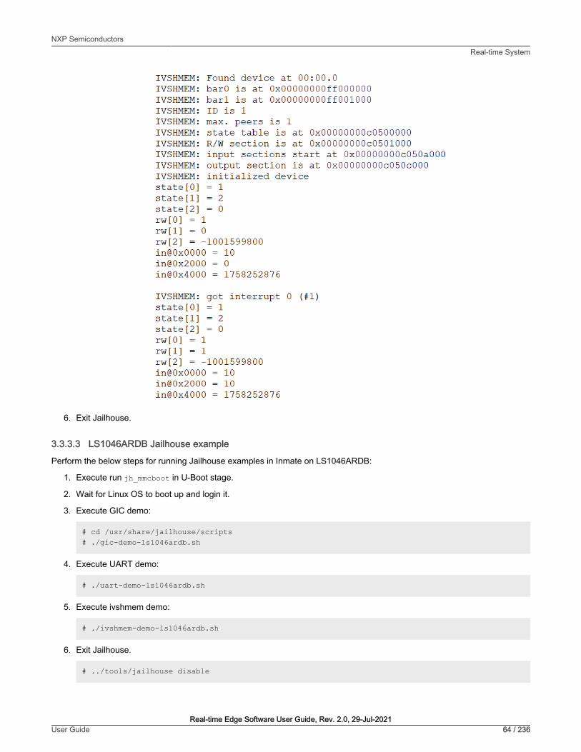
6. Exit Jailhouse.
3.3.3.3 LS1046ARDB Jailhouse example
Perform the below steps for running Jailhouse examples in Inmate on LS1046ARDB:
1. Execute run jh_mmcboot in U-Boot stage.
2. Wait for Linux OS to boot up and login it.
3. Execute GIC demo:
# cd /usr/share/jailhouse/scripts# ./gic-demo-ls1046ardb.sh
4. Execute UART demo:
# ./uart-demo-ls1046ardb.sh
5. Execute ivshmem demo:
# ./ivshmem-demo-ls1046ardb.sh
6. Exit Jailhouse.
# ../tools/jailhouse disable
NXP SemiconductorsReal-time System
Real-time Edge Software User Guide, Rev. 2.0, 29-Jul-2021User Guide 64 / 236
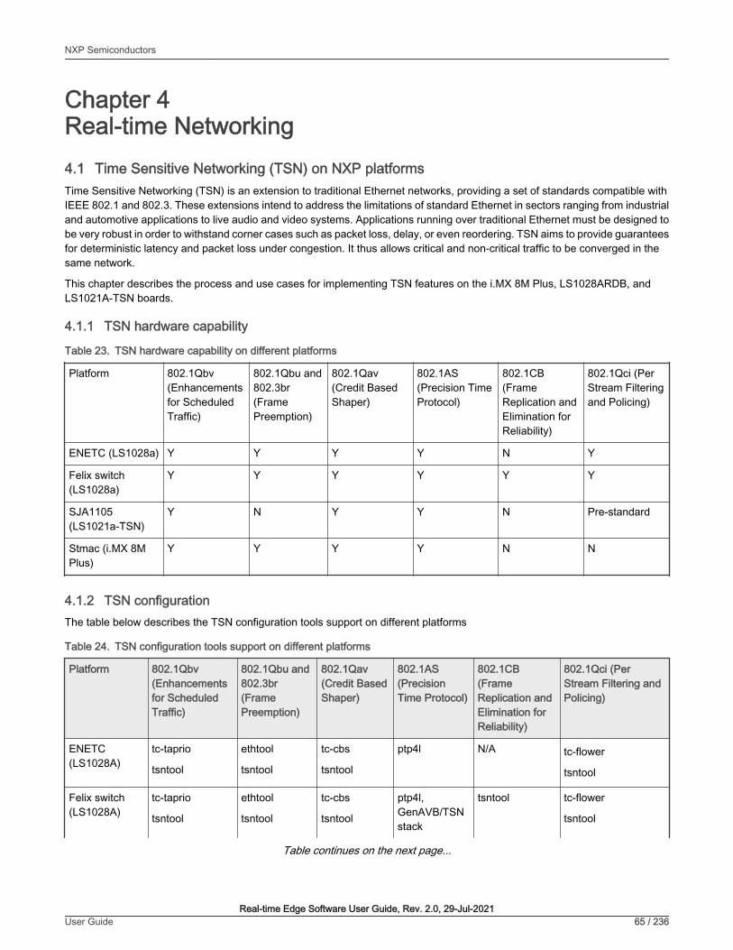
Chapter 4Real-time Networking4.1 Time Sensitive Networking (TSN) on NXP platformsTime Sensitive Networking (TSN) is an extension to traditional Ethernet networks, providing a set of standards compatible withIEEE 802.1 and 802.3. These extensions intend to address the limitations of standard Ethernet in sectors ranging from industrialand automotive applications to live audio and video systems. Applications running over traditional Ethernet must be designed tobe very robust in order to withstand corner cases such as packet loss, delay, or even reordering. TSN aims to provide guaranteesfor deterministic latency and packet loss under congestion. It thus allows critical and non-critical traffic to be converged in thesame network.
This chapter describes the process and use cases for implementing TSN features on the i.MX 8M Plus, LS1028ARDB, andLS1021A-TSN boards.
4.1.1 TSN hardware capability
Table 23. TSN hardware capability on different platforms
Platform 802.1Qbv(Enhancementsfor ScheduledTraffic)
802.1Qbu and802.3br(FramePreemption)
802.1Qav(Credit BasedShaper)
802.1AS(Precision TimeProtocol)
802.1CB(FrameReplication andElimination forReliability)
802.1Qci (PerStream Filteringand Policing)
ENETC (LS1028a) Y Y Y Y N Y
Felix switch(LS1028a)
Y Y Y Y Y Y
SJA1105(LS1021a-TSN)
Y N Y Y N Pre-standard
Stmac (i.MX 8MPlus)
Y Y Y Y N N
4.1.2 TSN configurationThe table below describes the TSN configuration tools support on different platforms
Table 24. TSN configuration tools support on different platforms
Platform 802.1Qbv(Enhancementsfor ScheduledTraffic)
802.1Qbu and802.3br(FramePreemption)
802.1Qav(Credit BasedShaper)
802.1AS(PrecisionTime Protocol)
802.1CB(FrameReplication andElimination forReliability)
802.1Qci (PerStream Filtering andPolicing)
ENETC(LS1028A)
tc-taprio
tsntool
ethtool
tsntool
tc-cbs
tsntool
ptp4l N/A tc-flower
tsntool
Felix switch(LS1028A)
tc-taprio
tsntool
ethtool
tsntool
tc-cbs
tsntool
ptp4l,GenAVB/TSNstack
tsntool tc-flower
tsntool
Table continues on the next page...
NXP Semiconductors
Real-time Edge Software User Guide, Rev. 2.0, 29-Jul-2021User Guide 65 / 236

Table 24. TSN configuration tools support on different platforms (continued)
Platform 802.1Qbv(Enhancementsfor ScheduledTraffic)
802.1Qbu and802.3br(FramePreemption)
802.1Qav(Credit BasedShaper)
802.1AS(PrecisionTime Protocol)
802.1CB(FrameReplication andElimination forReliability)
802.1Qci (PerStream Filtering andPolicing)
SJA1105(LS1021A-TSN)
tc-taprio N/A tc-cbs ptp4l N/A tc-flower
Stmac (i.MX8M Plus)
tc-taprio ethtool tc-cbs ptp4l,GenAVB/TSNstack
N/A N/A
4.1.2.1 Using Linux traffic control (tc)
Enable the following configurations in kernel when using Linux traffic control (tc):
Symbol: NET_SCH_MQPRIO [=y] && NET_SCH_CBS [=y] && NET_SCH_TAPRIO [=y] [*] Networking support ---> Networking options ---> [*] QoS and/or fair queueing ---> <*> Credit Based Shaper (CBS) <*> Time Aware Priority (taprio) Scheduler <*> Multi-queue priority scheduler (MQPRIO) [*] Actions ---> <*> Traffic Policing <*> Generic actions <*> Redirecting and Mirroring <*> SKB Editing <*> Vlan manipulation <*> Frame gate entry list control tc action
On lS1028A platform, ENETC QoS driver needs to be set to support tc configuration.
Symbol: FSL_ENETC_QOS [=y] Device Drivers---> [*] Network device support ---> [*] Ethernet driver support ---> [*] Freescale devices [*] ENETC hardware Time-sensitive Network support
1. The below link provides details for using tc-taprio to set Qbv:
https://man7.org/linux/man-pages/man8/tc-taprio.8.html
2. The below link provides details for using tc-cbs to set Qav:
https://man7.org/linux/man-pages/man8/tc-cbs.8.html
3. The below link provides details for using tc-flower to set Qci and ACL:
https://man7.org/linux/man-pages/man8/tc-flower.8.html
NXP SemiconductorsReal-time Networking
Real-time Edge Software User Guide, Rev. 2.0, 29-Jul-2021User Guide 66 / 236

4.1.2.2 Tsntool
Tsntool is a tool to set the TSN capability of the Ethernet ports of TSN Endpoint and TSN switch. It's used on LS1028a platform,so enable TSN, ENETC_TSN, and MSCC_FELIX_SWITCH_TSN to support tsntool configuration on LS1028a.
Symbol: TSN [=y] [*] Networking support ---> Networking options ---> [*] 802.1 Time-Sensitive Networking support
Symbol: ENETC_TSN [=y] && FSL_ENETC_PTP_CLOCK [=y] && FSL_ENETC_HW_TIMESTAMPING [=y] Device Drivers ---> [*] Network device support ---> [*] Ethernet driver support ---> [*] Freescale devices <*> ENETC PF driver <*> ENETC VF driver -*- ENETC MDIO driver <*> ENETC PTP clock driver [*] ENETC hardware timestamping support [*] TSN Support for NXP ENETC driver
Symbol: MSCC_FELIX_SWITCH_TSN [=y] Device Drivers ---> [*] Network device support ---> Distributed Switch Architecture drivers ---> <*> Ocelot / Felix Ethernet switch support ---> <*> TSN on FELIX switch driver
Enable PKTGEN in Kernel to use pktgen for testing,
Symbol: NET_PKTGEN [=y] [*] Networking support ---> Networking options ---> Network testing ---> <*> Packet Generator (USE WITH CAUTION)
See "Tsntool User Manual" for the details.
4.1.2.2.1 Tsntool User Manual
Tsntool is a tool to set the TSN capability of the Ethernet ports of TSN Endpoint and TSN switch. This document describes howto use tsntool for NXP's LS1028ARDB hardware platform.
Tsntool supports only the LS1028ARDB platform.
NOTE
4.1.2.2.1.1 Getting the source code
Github of the tsntool code is mentioned below.
https://source.codeaurora.org/external/qoriq/qoriq-components/tsntool/
4.1.2.2.1.2 Tsn tool commands
The following table lists the TSN tool commands and their description.
NXP SemiconductorsReal-time Networking
Real-time Edge Software User Guide, Rev. 2.0, 29-Jul-2021User Guide 67 / 236

Table 25. TSN tool commands and their description
Command Description
help Lists commands support
version Shows software version
verbose Debugs on/off for tsntool
quit Quits prompt mode
qbvset Sets time gate scheduling config for <ifname>
qbvget Gets time scheduling entries for <ifname>
cbstreamidset Sets stream identification table
cbstreamidget Gets stream identfication table and counters
qcisfiset Sets stream filter instance
qcisfiget Gets stream filter instance
qcisgiset Sets stream gate instance
qcisgiget Gets stream gate instance
qcisficounterget Gets stream filter counters
qcifmiset Sets flow metering instance
qcifmiget Gets flow metering instance
cbsset Sets TCs credit-based shaper configure
cbsget Gets TCs credit-based shaper status
qbuset Sets one 8-bits vector showing the preemptable traffic class
qbugetstatus Not supported
tsdset Not supported
tsdget Not supported
ctset Sets cut through queue status (specific for ls1028 switch)
cbgen Sets sequence generate configure (specific for ls1028 switch)
cbrec Sets sequence recover configure (specific for ls1028 switch)
dscpset Sets queues map to DSCP of Qos tag (specific for ls1028 switch)
sendpkt Not supported
Table continues on the next page...
NXP SemiconductorsReal-time Networking
Real-time Edge Software User Guide, Rev. 2.0, 29-Jul-2021User Guide 68 / 236

Table 25. TSN tool commands and their description (continued)
Command Description
regtool Registers read/write of bar0 of PFs (specific for ls1028 enetc)
ptptool ptptool get/set ptp timestamp. Useful commands:
#get ptp0 clock timeptptool -g
#get ptp1 clock time ptptool -g -d /dev/ptp1
dscpset Set queues map to DSCP of QoS tag (specific for ls1028 switch)
qcicapget Gets max capability of the qci instance
tsncapget Gets tsn capability of the device
4.1.2.2.1.3 Tsntool commands and parameters
This section lists the tsntool commands along with the parameters and arguments, with which they can be used.
Table 26. qbvset
Parameter <argument> Description
--device <ifname> An interface such as eno0/swp0.
--entryfile <filename> A file script to input gatelist format. It has the following arguments:
#'NUMBER' 'GATE_VALUE' 'TIME_LONG'
• NUMBER: # 't' or 'T' head. Plus entry number. Duplicate entry number will result in an error.
• GATE_VALUE: # format: xxxxxxxxb . # The MSB corresponds to traffic class 7. The LSBcorresponds to traffic class 0. # A bit value of 0 indicates closed, whereas, a bit value of 1indicates open.
• TIME_LONG: # nanoseconds. Do not input 0 time long.
t0 11101111b 10000 t1 11011111b 10000
Entryfile parameter must be set. If not set, there will be a vi text editorprompt, "require to input the gate list".
NOTE
--basetime <value> AdminBaseTime
A 64-bit hex value means nano second until now.
OR a value input format as: Seconds.decimalSecond
Example: 115.000125means 115 seconds and 125 μs.
--cycletime <value> AdminCycleTime
Table continues on the next page...
NXP SemiconductorsReal-time Networking
Real-time Edge Software User Guide, Rev. 2.0, 29-Jul-2021User Guide 69 / 236

Table 26. qbvset (continued)
Parameter <argument> Description
--cycleextend <value> AdminCycleTimeExtension
--enable | --disable • enable: enables the qbv for this port.
• disable: disables the qbv for this port.
By default, the value is set to enable, if user does not provide any input.
--maxsdu <value> queueMaxSDU
--initgate <value> AdminGateStates
--configchange ConfigChange. Default set to 1.
--configchangetime <value>
ConfigChangeTime
Table 27. qbvget
Parameter <argument> Description
--device <ifname> An interface such as eno0/swp0
Table 28. cbstreamidset
Parameter <argument> Description
--enable | --disable • enable: Enables the entry for this index.
• disable: Disables the entry for this index.
By default, this field is set to enable if there is no enable or disable input.
--index <value> Index entry number in this controller. Mandatory parameter.
This value corresponds to tsnStreamIdHandle on switch configuration.
--device <string> An interface such as eno0/swp0
--streamhandle <value> tsnStreamIdHandle
--infacoutport <value> tsnStreamIdInFacOutputPortList
--outfacoutport <value> tsnStreamIdOutFacOutputPortList
--infacinport <value> tsnStreamIdInFacInputPortList
--outfacinport <value> tsnStreamIdOutFacInputPortList
--nullstreamid | --sourcemacvid | --destmacvid | --ipstreamid
tsnStreamIdIdentificationType:
Table continues on the next page...
NXP SemiconductorsReal-time Networking
Real-time Edge Software User Guide, Rev. 2.0, 29-Jul-2021User Guide 70 / 236

Table 28. cbstreamidset (continued)
Parameter <argument> Description
• -nullstreamid:Null Stream identification
• -sourcemacvid: Source MAC and VLAN Stream identification
• -destmacvid: not supported
• -ipstreamid: not supported
--nulldmac <value> tsnCpeNullDownDestMac
--nulltagged <value> tsnCpeNullDownTagged
--nullvid <value> tsnCpeNullDownVlan
--sourcemac <value> tsnCpeSmacVlanDownSrcMac
--sourcetagged <value> tsnCpeSmacVlanDownTagged
--sourcevid <value> tsnCpeSmacVlanDownVlan
Table 29. cbstreamidget
Parameter <argument> Description
--device <ifname> An interface such as eno0/swp0
--index <value> Index entry number in this controller. Mandatory to have.
Table 30. qcisfiset
Parameter <argument> Description
--device <ifname> An interface such as eno0/swp0
--enable | --disable • enable: enable the entry for this index
• disable: disable the entry for this index
By default, this field is set to enable if there is no enable or disable input.
--maxsdu <value> Maximum SDU size.
--flowmeterid <value> Flow meter instance identifier index number.
--index <value> StreamFilterInstance. index entry number in this controler.
This value corresponds to tsnStreamIdHandle of cbstreamidset command onswitch configuration.
--streamhandle <value> StreamHandleSpec
This value corresponds to tsnStreamIdHandle of cbstreamidset command.
Table continues on the next page...
NXP SemiconductorsReal-time Networking
Real-time Edge Software User Guide, Rev. 2.0, 29-Jul-2021User Guide 71 / 236

Table 30. qcisfiset (continued)
Parameter <argument> Description
--priority <value> PrioritySpec
--gateid <value> StreamGateInstanceID
--oversizeenable StreamBlockedDueToOversizeFrameEnable
--oversize StreamBlockedDueToOversizeFrame
Table 31. qcisfiget
parameter <argument> Description
--device <ifname> An interface such as eno0/swp0
--index <value> Index entry number in this controller. Mandatory to have.
Table 32. qcisgiset
Parameter <argument> Description
--device <ifname> An interface such as eno0/swp0
--index <value> Index entry number in this controller. Mandatory to have.
--enable | --disable • enable: enable the entry for this index. PSFPGateEnabled
• disable: disable the entry for this index.
By default, this field is set to enable if there is no enable or disable input.
--configchange configchange
--enblkinvrx PSFPGateClosedDueToInvalidRxEnable
--blkinvrx PSFPGateClosedDueToInvalidRx
--initgate PSFPAdminGateStates
--initipv AdminIPV
--cycletime Default not set. Get by gatelistfile.
--cycletimeext PSFPAdminCycleTimeExtension
--basetime PSFPAdminBaseTime
A 64-bit hex value means nano second until now.
OR a value input format as: Seconds.decimalSecond
Example: 115.000125means 115 seconds and 125 μs.
Table continues on the next page...
NXP SemiconductorsReal-time Networking
Real-time Edge Software User Guide, Rev. 2.0, 29-Jul-2021User Guide 72 / 236

Table 32. qcisgiset (continued)
Parameter <argument> Description
--gatelistfile PSFPAdminControlList. A file input the gate list: 'NUMBER' 'GATE_VALUE' 'IPV''TIME_LONG' 'OCTET_MAX'
• NUMBER: # 't' or 'T' head. Plus entry number. Duplicate entry number will result in an error.
• GATE_VALUE: format: xb: The MSB corresponds to traffic class 7. The LSB corresponds totraffic class 0. A bit value of 0 indicates closed, A bit value of 1 indicates open.
• IPV: # 0~7
• TIME_LONG: in nanoseconds. Do not input time long as 0.
• OCTET_MAX: The maximum number of octets that are permitted to pass the gate. If zero,there is no maximum.
Example:
t0 1b -1 50000 10
Table 33. qcisgiget
Parameter <argument> Description
--device <ifname> An interface such as eno0/swp0
--index <value> Index entry number in this controller. Mandatory to have.
Table 34. qcifmiset
Parameter <argument> Description
--device <ifname> An interface such as eno0/swp0
--index <value> Index entry number in this controller. Mandatory to have.
--disable If not set disable, then to be set enable.
--cir <value> cir. kbit/s.
--cbs <value> cbs. octets.
--eir <value> eir.kbit/s.
--ebs <value> ebs.octets.
--cf cf. couple flag.
--cm cm. color mode.
--dropyellow drop yellow.
--markred_enable mark red enable.
Table continues on the next page...
NXP SemiconductorsReal-time Networking
Real-time Edge Software User Guide, Rev. 2.0, 29-Jul-2021User Guide 73 / 236

Table 34. qcifmiset (continued)
Parameter <argument> Description
--markred mark red.
Table 35. qcifmiget parameter
Parameter <argument> Description
--device <ifname> An interface such as eno0/swp0
--index <value> Index entry number in this controller. Mandatory to have.
Table 36. qbuset parameter
Parameter <argument> Description
--device <ifname> An interface such as eno0/swp0
--preemptable <value> 8-bit hex value. Example: 0xfe The MS bit corresponds to traffic class 7.
The LS bit to traffic class 0. A bit value of 0 indicates express. A bit value of 1indicates preemptable.
Table 37. cbsset command
Parameter <argument> Description
--device <ifname> An interface such as eno0/swp0
--tc <value> Traffic class number.
--percentage <value> Set percentage of tc limitation.
--all <tc-percent:tc-percent...>
Not supported.
Table 38. cbsget
Parameter <argument> Description
--device <ifname> An interface such as eno0/swp0
--tc <value> Traffic class number.
NXP SemiconductorsReal-time Networking
Real-time Edge Software User Guide, Rev. 2.0, 29-Jul-2021User Guide 74 / 236

Table 39. regtool
Parameter <argument> Description
Usage: regtool { pf number }{ offset } [ data ]
pf number: pf number for the pci resource to act on
offset: offset into pci memory region to act upon
data: data to be written
Table 40. ctset
Parameter <argument> Description
--device <ifname> An interface such as swp0
--queue_stat <value> Specifies which priority queues have to be processed in cut-through mode of operation. Bit 0corresponds to priority 0, Bit 1 corresponds to priority 1 so-on.
Table 41. cbgen
Parameter <argument> Description
--device <ifname> An interface such as swp0
--index <value> Index entry number in this controller. Mandatory to have.
This value corresponds to tsnStreamIdHandle of cbstreamidset command.
--iport_mask <value> INPUT_PORT_MASK: If the packet is from input port belonging to this port mask, then it's aknown stream and Sequence generation parameters can be applied
--split_mask <value> SPLIT_MASK: Port mask used to add redundant paths (or ports). If split is enabled(STREAM_SPLIT) for a stream. This is OR'ed with the final port mask determined by theforwarding engine.
--seq_len <value> SEQ_SPACE_LOG2: Minimum value is 1 and maximum value is 28.
tsnSeqGenSpace = 2**SEQ_SPACE_LOG2
For example, if this value is 12, then valid sequence numbers are from 0x0 to 0xFFF.
--seq_num <value> GEN_REC_SEQ_NUM: The sequence number to be used for outgoing packet passed toSEQ_GEN function.
Note: Only lower 16-bits are sent in RED_TAG.
Table 42. cbrec
Parameter <argument> Description
--device <ifname> An interface such as swp0
--index <value> Index entry number in this controller. Mandatory to have.
Table continues on the next page...
NXP SemiconductorsReal-time Networking
Real-time Edge Software User Guide, Rev. 2.0, 29-Jul-2021User Guide 75 / 236

Table 42. cbrec (continued)
Parameter <argument> Description
This value corresponds to tsnStreamIdHandle of cbstreamidset command.
--seq_len <value> SEQ_SPACE_LOG2:Min value is 1 and maximum value is 28.
tsnSeqRecSeqSpace = 2**SEQ_REC_SPACE_LOG2
For example, if this value is 12, then valid sequence numbers are from 0x0 to 0xFFF.
--his_len <value> SEQ_HISTORY_LEN: Refer to SEQ_HISTORY, Min 1 and Max 32.
--rtag_pop_en REDTAG_POP: If True, then the redundancy tag is popped by rewriter.
Table 43. dscpset
Parameter <argument> Description
--device <ifname> An interface such as swp0
--disable Disables DSCP to traffic class for frames.
--index DSCP value
--cos Priority number of queue which is mapped to
--dpl Drop level which is mapped to
Table 44. qcicapget
Parameter <argument> Description
--device <ifname> An interface such as swp0
Table 45. tsncapget
Parameter <argument> Description
--device <ifname> An interface such as swp0
4.1.2.2.1.4 Input tips
While providing the command input, user can use the following shortcut keys to make the input faster:
• When user input a command, use the TAB key to help list the related commands.
For example:
tsntool> qbv
Then press TAB key, to get all related qbv* start commands.
If there is only one choice, it is filled as the whole command automatically.
• When user input parameters, if user does nott remember the parameter name. User can just input “--” then press TABkey. It displays all the parameters.
NXP SemiconductorsReal-time Networking
Real-time Edge Software User Guide, Rev. 2.0, 29-Jul-2021User Guide 76 / 236

If user input half the parameter’s name, pressing the TAB key lists all the related names.
• History: press the up arrow “↑” . User will get the command history and can re-use the command.
4.1.2.2.1.5 Non-interactive mode
Tsntool also supports non-interactive mode.
For example:
In the interactive mode:
tsntool> qbuset --device eno0 --preemptable 0xfe
In non-interactive mode:
tsntool qbuset --device eno0 --preemptable 0xfe
4.1.2.3 Remote configuration using NETCONF/YANG
1. Overview
The NETCONF protocol defines a mechanism for device management and configuration retrieval and modification. It enables aclient to adjust to the specific features of any network equipment by using a remote procedure call (RPC) paradigm and a systemto expose device (server) capabilities.
YANG is a standards-based, extensible, hierarchical data modeling language. YANG is used to model the configuration and statedata used by NETCONF operations, RPCs, and server event notifications.
2. Support for different platforms in Real-time Edge
TSN offload Real-time Edge
LS1028 SJA1105 i.MX 8M Plus
libtsn tc tc tc
802.1Qbv
(Time Aware Shaper)
Y Y Y Y
802.1Qbu/802.3br
(Frame Preemption)
Y Y N/A Y
802.1Qav
(Credit Based Shaper)
- - - -
802.1CB (Frame Replication and Eliminationfor Reliability)
- - N/A N/A
802.1Qci
(Per-Stream Filtering and Policing)
Y Y Y N/A
IP config Y Y Y Y
MAC config Y Y Y Y
VLAN config Y Y Y Y
3. Installation and configuration
NXP SemiconductorsReal-time Networking
Real-time Edge Software User Guide, Rev. 2.0, 29-Jul-2021User Guide 77 / 236

Netopeer is a set of NETCONF tools built on the libnetconf library. The sysrepo-tsn (https://github.com/real-time-edge-sw/real-time-edge-sysrepo.git) helps to configure TSN features, including Qbv, Qbu, Qci, and stream identification via network,without logging in to device. For details of configuring TSN features via Netopeer, refer to NETCONF/YANG). Some applicationscenarios for tsn refer to Application scenarios.
4.1.2.4 Web-based configuration
4.1.2.4.1 Setting up web server
The Web UI allows the remote control of the YANG model and also get devices information by websockets. This demo is alreadyadded to tsntool in the folder tsntool/demos/cnc/.
There are two ways to start the web server on PC side: docker or install step by step.
The easy way to start the webserver on PC side, just run command at Ubuntu PC(install docker support):
docker run --net=host -t -i liupoer/cncdemo:v2.0 /bin/bash /etc/rc.d/rc.local
Then just step over to the step 8 start the agent on boards directly.
In case user want to setup the web server step by step, just follow below steps one by one:
1. Install related libraries: Suppose user is installing the demo on a Centos PC or Ubuntu PC as the WebServer. CNC demorequires python3 and related libraries: pyang, libnetconf, and libssh.
For Ubuntu:
$ sudo apt install -y libtool python-argparse libtool-bin python-sphinx libffi-dev$ sudo apt install -y libxslt1-dev libcurl4-openssl-dev xsltproc python-setuptools$ sudo apt install -y zlib1g-dev libssl-dev python-libxml2 libaugeas-dev$ sudo apt install -y libreadline-dev python-dev pkg-config libxml2-dev$ sudo apt install -y cmake openssh-server$ sudo apt install -y python3-sphinx python3-setuptools python3-libxml2$ sudo apt install -y python3-pip python3-dev python3-flask python3-pexpect$ sudo apt install -y libnss-mdns avahi-utils$ pip3 install flask-restful$ pip3 install websockets
For Centos 7.2:
$ sudo yum install libxml2-devel libxslt-devel openssl-devel libgcrypt dbus-devel$ sudo yum install doxygen libevent readline.x86_64 ncurses-libs.x86_64$ sudo yum install ncurses-devel.x86_64 libssh.x86_64 libssh2-devel.x86_64$ sudo yum install libssh2.x86_64 libssh2-devel.x86_64$ sudo yum install nss-mdns avahi avahi-tools
2. Install pyang
$ git clone https://github.com/mbj4668/pyang.git$ cd pyang$ git checkout b92b17718de53758c4c8a05b6818ea66fc0cd4d8 -b fornetconf1$ sudo python setup.py install
3. . Install libssh:
$ git clone https://git.libssh.org/projects/libssh.git$ cd libssh$ git checkout fe18ef279881b65434e3e44fc4743e4b1c7cb891 -b fornetconf1$ mkdir build; cd build/$ cmake ..
NXP SemiconductorsReal-time Networking
Real-time Edge Software User Guide, Rev. 2.0, 29-Jul-2021User Guide 78 / 236

$ make$ sudo make install
There is a version issue for libssh installation on Ubuntu below version 16.04. Apt-get install libssh may get version0.6.4. But libnetconf needs a version of 0.7.3 or later. Remove the default one and reinstall by downloading thesource code and installing it manually.
NOTE
4. Install libnetconf:
$ git clone https://github.com/CESNET/libnetconf.git$ cd libnetconf$ git checkout 8e934324e4b1e0ba6077b537e55636e1d7c85aed -b fornetconf1$ autoreconf --force --install$ ./configure$ make$ sudo make install
5. Get tsntool source code on webserver PC
git clone https://source.codeaurora.org/external/qoriq/qoriq-components/tsntool cd tsntool/demos/cnc/
6. Install python library:
In the below command segments,
• PATH-to-libnetconf is the path to the libnetconf source code.
• PATH-to-tsntool is the path to the tsntool source code.
$ cd PATH-to-libnetconf/
The libnetconf needs to add two patches based on the below commit point to fix the demo python support.
Ensure that the commit id is 313fdadd15427f7287801b92fe81ff84c08dd970.
$ git checkout 313fdadd15427f7287801b92fe81ff84c08dd970 -b cnc-server$ cp PATH-to-tsntool/demos/cnc/*patch .$ git am 0001-lnctool-to-make-install-transapi-yang-model-proper.patch$ git am 0002-automatic-python3-authorizing-with-root-password-non.patch$ cd PATH-to-libnetconf/python$ python3 setup.py build; sudo python3 setup.py install
If rebuilding python lib, user need to remove the build folder by command rm build -rf before rebuilding. On theboards Real-time Edge supports, avahi-daemon and netopeer server are required. Remember to also add thenetopeer2-server run at boards.
NOTE
7. To start the web server on webserver PC, input the command below at shell into the folder: PATH-to-tsntool/demos/cnc/:
sudo python3 cnc.py
8. Start topoagent server on the boards supported
- Make sure the netopeer2-server run at boards(Not necessary for topology discovery).
- Make sure the lldpd daemon is running at boards.
- Make sure the avahi-daemon is running at boards.
NXP SemiconductorsReal-time Networking
Real-time Edge Software User Guide, Rev. 2.0, 29-Jul-2021User Guide 79 / 236

Start the topology server on boards:
#If the hostname is not real-time-edge, change to real-time-edge avahi-set-host-name real-time-edge cd /home/root/samples/cncdemo/ python3 topoagent.py
9. Use Web browser to track the devices topology and configuration. Input the IP of WebServer with the port 8180 at browser.For example:
http://10.193.20.147:8180
TSN configuration debug:
• It is recommended to track the boards using tsntool to check the real tsn configuration for comparison.
• It is also recommended to track if the netopeer2-server is running at board or not for tsn configuration.
Limitations of Web UI are::
• Setup server on a Centos PC or Ubuntu PC could be more compatible.
• Supports Qbv, Qbu and Qci in current version.
• For Qci setting, Stream-gate entry should be set ahead of setting the Stream-filter as sysrepo required. Orelse, user will get failure for setting Stream-filter without a stream gate id link to.
• The boards and the web server PC are required to be in same IP domain since the bridge may block theprobe frames.
NOTE
4.1.2.4.2 Remote configuration
1. Overview
The Web UI allows the remote control of the YANG model. The user can connect http server, and input TSN parameter on webUI, and click "Yes, confirm" button to send them to the board.
NXP SemiconductorsReal-time Networking
Real-time Edge Software User Guide, Rev. 2.0, 29-Jul-2021User Guide 80 / 236
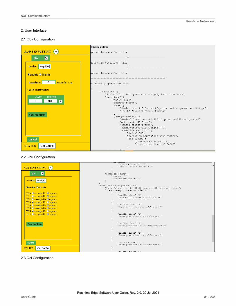
2. User Interface
2.1 Qbv Configuration
2.2 Qbu Configuration
2.3 Qci Configuration
NXP SemiconductorsReal-time Networking
Real-time Edge Software User Guide, Rev. 2.0, 29-Jul-2021User Guide 81 / 236

In this interface, user can choose configuration for "stream identify", "stream filter", "stream gate" and "flow metering".
4.1.3 TSN on i.MX 8M Plus
4.1.3.1 Test environment
On i.MX 8M Pluse platform, there is only eth1 has TSN features, connect eth1 to Test center to test TSN features.
Figure 13. TSN test environment setup
NXP SemiconductorsReal-time Networking
Real-time Edge Software User Guide, Rev. 2.0, 29-Jul-2021User Guide 82 / 236

Note: Test Center is a device to capture streams from eth1 of i.mx8mp board. We use Spirent which can capture preemptableframes in Qbu test case.
4.1.3.2 Clock synchronization
To test 1588 synchronization on dwcmac interfaces, use the following procedure:
1. Connect eth1 interfaces on two boards in a back-to-back manner.
The linux booting log is as follows:
…pps pps0: new PPS source ptp0…
2. Configure the IP address
ifconfig eth1 192.168.3.1
3. Check PTP clock and timestamping capability:
# ethtool -T eth1Time stamping parameters for eth1:Capabilities: hardware-transmit (SOF_TIMESTAMPING_TX_HARDWARE) software-transmit (SOF_TIMESTAMPING_TX_SOFTWARE) hardware-receive (SOF_TIMESTAMPING_RX_HARDWARE) software-receive (SOF_TIMESTAMPING_RX_SOFTWARE) software-system-clock (SOF_TIMESTAMPING_SOFTWARE) hardware-raw-clock (SOF_TIMESTAMPING_RAW_HARDWARE)PTP Hardware Clock: 1Hardware Transmit Timestamp Modes: off (HWTSTAMP_TX_OFF) on (HWTSTAMP_TX_ON)Hardware Receive Filter Modes: none (HWTSTAMP_FILTER_NONE) all (HWTSTAMP_FILTER_ALL) ptpv1-l4-event (HWTSTAMP_FILTER_PTP_V1_L4_EVENT) ptpv1-l4-sync (HWTSTAMP_FILTER_PTP_V1_L4_SYNC) ptpv1-l4-delay-req (HWTSTAMP_FILTER_PTP_V1_L4_DELAY_REQ) ptpv2-l4-event (HWTSTAMP_FILTER_PTP_V2_L4_EVENT) ptpv2-l4-sync (HWTSTAMP_FILTER_PTP_V2_L4_SYNC) ptpv2-l4-delay-req (HWTSTAMP_FILTER_PTP_V2_L4_DELAY_REQ) ptpv2-event (HWTSTAMP_FILTER_PTP_V2_EVENT) ptpv2-sync (HWTSTAMP_FILTER_PTP_V2_SYNC) ptpv2-delay-req (HWTSTAMP_FILTER_PTP_V2_DELAY_REQ)
4. Run ptp4l on two boards:
ptp4l -i eth1 -p /dev/ptp1 -m -2
5. After running, one board would be automatically selected as the master, and the slave board would printsynchronization messages.
6. For 802.1AS testing, just use the configuration file gPTP.cfg in linuxptp source. Run the below command on the boards, instead:
ptp4l -i eth1 -p /dev/ptp1 -f /etc/ptp4l_cfg/gPTP.cfg -m
Or use GenAVB/TSN Stack with the following command: 'avb.sh start'. Note that the configuration file /etc/genavb/fgptp.cfg is automatically used.
NXP SemiconductorsReal-time Networking
Real-time Edge Software User Guide, Rev. 2.0, 29-Jul-2021User Guide 83 / 236
i.MX 8M Plus current dwmac driver (eth1) initializes few hardware functions while opening net device, includingPTP initialization. Before that, the operations such as ethtool queries, and PTP operations might not work. So, theworkaround is to do operations on the eth1 and PTP of dwmac only after "ifconfig eth1 up".
NOTE
4.1.3.3 Qbv
1. Enable the ptp device, and get the current ptp time.
ptp4l -i eth1 -p /dev/ptp1 -m
#Get current time(seconds)devmem2 0x30bf0b080x5E01F9B2
2. Get the basetime to be 2 minutes later.
#Basetime = (currentime + 120) * 1000000000 = 1577187882000000000
3. Set time schedule, open queue 1 in 100 µs and open queue 2 in 100 µs.
tc qdisc replace dev eth1 parent root handle 100 taprio \ num_tc 5 map 0 1 2 3 4 queues 1@0 1@1 1@2 1@3 1@4 base-time 1577187882000000000 \ sched-entry S 1 100000 \ sched-entry S 2 100000 \ sched-entry S 4 100000 flags 2
4. Send two streams into queue 1 and queue 2.
/home/root/samples/pktgen/pktgen_twoqueue.sh -i eth1 -q 1 -s 1000 -n 0 -m 90:e2:ba:ff:ff:ff
5. Capture the streams on TestCenter, 100 µs queue 1 frames (length=1004) and 100 µs queue 2 frames (length=1504) will be got.Or if the Ethernet port is connected to another board, the frames can be captured on that board by using Linux tcpdump commandas shown below:
tcpdump -i eth0 -e -n -t -xx -c 10000 -w tsn.pcap
Then Wireshark can be used to analyze the pcap file on host PC.
• More than one entry needs to be set on each tc taprio command.
• Use “devmem2 0x30bf0c58” to get Qbv status and check if qbv status is active. refer toMTL_EST_Status register.
NOTE
4.1.3.4 Qbu
1. Using ethtool to enable Qbu on eth1, set queue 2 to be preemptable.
ethtool --set-frame-preemption eth1 preemptible-queues-mask 0x04 min-frag-size 60
Once Qbu enabled, queue 0 is always preemptable queue.
NOTE
NXP SemiconductorsReal-time Networking
Real-time Edge Software User Guide, Rev. 2.0, 29-Jul-2021User Guide 84 / 236
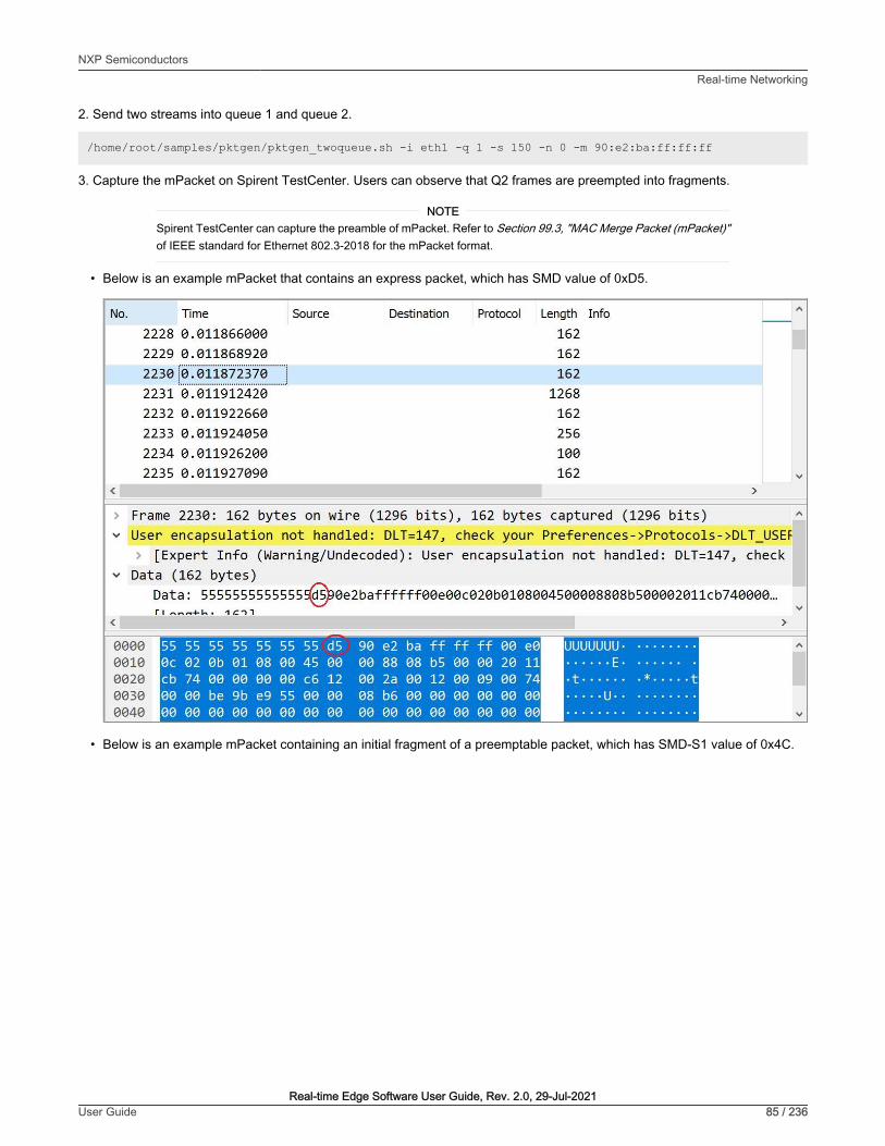
2. Send two streams into queue 1 and queue 2.
/home/root/samples/pktgen/pktgen_twoqueue.sh -i eth1 -q 1 -s 150 -n 0 -m 90:e2:ba:ff:ff:ff
3. Capture the mPacket on Spirent TestCenter. Users can observe that Q2 frames are preempted into fragments.
Spirent TestCenter can capture the preamble of mPacket. Refer to Section 99.3, "MAC Merge Packet (mPacket)"of IEEE standard for Ethernet 802.3-2018 for the mPacket format.
NOTE
• Below is an example mPacket that contains an express packet, which has SMD value of 0xD5.
• Below is an example mPacket containing an initial fragment of a preemptable packet, which has SMD-S1 value of 0x4C.
NXP SemiconductorsReal-time Networking
Real-time Edge Software User Guide, Rev. 2.0, 29-Jul-2021User Guide 85 / 236

• Below is an example mPacket containing a continuation fragment of a preemptable packet, which has SMD-C1 value of 0x52,as well as frag_count value of 0xE6.
NXP SemiconductorsReal-time Networking
Real-time Edge Software User Guide, Rev. 2.0, 29-Jul-2021User Guide 86 / 236
4. User can also check the below counter for the number of fragments transmitted.
ethtool -S eth1 | grep "mmc_tx_fpe_fragment_cntr"
5. Qbu combined with Qbv test
Once a queue is set to preemptable queue and the gate open/close is invalid in Qbv gate control list, the queue is consideredas always "Open". Use Hold/Release to control all preemptable queues. When the GCL entry is set from Hold to Release,preemptable queues begin transmitting. When GCL entry is set from Release to Hold, preemptable queues are held.
tc qdisc replace dev eth1 parent root handle 100 taprio \ num_tc 5 map 0 1 2 3 4 queues 1@0 1@1 1@2 1@3 1@4 base-time 1577187882000000000 \ sched-entry H 2 100000 \ sched-entry R 4 100000 flags 2
4.1.3.5 Qav
1. Set a queue map handle.
tc qdisc add dev eth1 root handle 1: mqprio num_tc 5 map 0 1 2 3 4
2. Set bandwidth of queue 3 to be 20Mbps
tc qdisc replace dev eth1 parent 1:4 cbs locredit -1470 hicredit 30 sendslope -980000 idleslope 20000 offload 1
3. Send a stream into queue 3
/home/root/samples/pktgen/pktgen_sample01_simple.sh -i eth1 -q 3 -s 500 -n 3000
4. Get the result, bandwidth is 19Mbps.
WARN : Missing destination MAC addressWARN : Missing destination IP addressRunning... ctrl^C to stopDoneResult device: eth1Params: count 3000 min_pkt_size: 500 max_pkt_size: 500 frags: 0 delay: 0 clone_skb: 0 ifname: eth1 flows: 0 flowlen: 0 queue_map_min: 3 queue_map_max: 3 dst_min: 198.18.0.42 dst_max: src_min: src_max: src_mac: a6:85:82:fc:89:bf dst_mac: 02:5d:ae:ba:e0:00 udp_src_min: 9 udp_src_max: 109 udp_dst_min: 9 udp_dst_max: 9 src_mac_count: 0 dst_mac_count: 0 Flags: UDPSRC_RND NO_TIMESTAMP QUEUE_MAP_RNDCurrent: pkts-sofar: 3000 errors: 0 started: 5631940023us stopped: 5632560030us idle: 79984us seq_num: 3001 cur_dst_mac_offset: 0 cur_src_mac_offset: 0 cur_saddr: 0.0.0.0 cur_daddr: 198.18.0.42 cur_udp_dst: 9 cur_udp_src: 41 cur_queue_map: 3 flows: 0Result: OK: 620007(c540023+d79984) usec, 3000 (500byte,0frags) 4838pps 19Mb/sec (19352000bps) errors: 0
NXP SemiconductorsReal-time Networking
Real-time Edge Software User Guide, Rev. 2.0, 29-Jul-2021User Guide 87 / 236

5. Set bandwidth of queue 4 to be 40Mbps
tc qdisc replace dev eth1 parent 1:5 cbs locredit -1440 hicredit 60 sendslope -960000 idleslope 40000 offload 1
6. Send a stream into queue 4 and get the result.
/home/root/samples/pktgen/pktgen_sample01_simple.sh -i eth1 -q 4 -s 500 -n 3000 WARN : Missing destination MAC address WARN : Missing destination IP address Running... ctrl^C to stop Done Result device: eth1 Params: count 3000 min_pkt_size: 500 max_pkt_size: 500 frags: 0 delay: 0 clone_skb: 0 ifname: eth1 flows: 0 flowlen: 0 queue_map_min: 4 queue_map_max: 4 dst_min: 198.18.0.42 dst_max: src_min: src_max: src_mac: a6:85:82:fc:89:bf dst_mac: 02:5d:ae:ba:e0:00 udp_src_min: 9 udp_src_max: 109 udp_dst_min: 9 udp_dst_max: 9 src_mac_count: 0 dst_mac_count: 0 Flags: UDPSRC_RND NO_TIMESTAMP QUEUE_MAP_RND Current: pkts-sofar: 3000 errors: 0 started: 6113136017us stopped: 6113443758us idle: 38457us seq_num: 3001 cur_dst_mac_offset: 0 cur_src_mac_offset: 0 cur_saddr: 0.0.0.0 cur_daddr: 198.18.0.42 cur_udp_dst: 9 cur_udp_src: 17 cur_queue_map: 4 flows: 0 Result: OK: 307741(c269283+d38457) usec, 3000 (500byte,0frags) 9748pps 38Mb/sec (38992000bps) errors: 0
7. Send two streams into queue 3 and queue 4
/home/root/samples/pktgen/pktgen_twoqueue.sh -i eth1 -q 3 -s 1500 -n 0
8. Capture the streams on test center, the frames sort by one Q3 frame and two Q4 frames
4.1.4 TSN on LS1028AThe tsntool is an application configuration tool to configure the TSN capability on LS1028ARDB. The files /usr/bin/tsntooland /usr/lib/libtsn.so are located in the rootfs. Run tsntool to start the setting shell.
4.1.4.1 TSN configuration on ENETC
The tsntool is an application configuration tool to configure the TSN capability. Users can find the files /usr/bin/tsntooland /usr/lib/libtsn.so in the rootfs. Run tsntool to start the setting shell. The following sections describe the TSNconfiguration examples on the ENETC Ethernet driver interfaces.
Before testing the ENETC TSN test cases, you must enable mqprio by using the command below:
tc qdisc add dev eno0 root handle 1: mqprio num_tc 8 map 0 1 2 3 4 5 6 7 hw 1
4.1.4.1.1 Clock synchronization
To test 1588 synchronization on ENETC interfaces, use the following procedure:
1. Connect ENETC interfaces on two boards in a back-to-back manner. (For example, eno0 to eno0.)
NXP SemiconductorsReal-time Networking
Real-time Edge Software User Guide, Rev. 2.0, 29-Jul-2021User Guide 88 / 236

The linux booting log is as follows:
…pps pps0: new PPS source ptp0…
2. Check PTP clock and timestamping capability:
# ethtool -T eno0Time stamping parameters for eno0:Capabilities: hardware-transmit (SOF_TIMESTAMPING_TX_HARDWARE) hardware-receive (SOF_TIMESTAMPING_RX_HARDWARE) hardware-raw-clock (SOF_TIMESTAMPING_RAW_HARDWARE)PTP Hardware Clock: 0Hardware Transmit Timestamp Modes: off (HWTSTAMP_TX_OFF) on (HWTSTAMP_TX_ON)Hardware Receive Filter Modes: none (HWTSTAMP_FILTER_NONE) all (HWTSTAMP_FILTER_ALL)
3. Configure the IP address and run ptp4l on two boards:
# ifconfig eno0 <ip_addr># ptp4l -i eno0 -p /dev/ptp0 -m
4. After running, one board would be automatically selected as the master, and the slave board would printsynchronization messages.
5. For 802.1AS testing, just use the configuration file gPTP.cfg in linuxptp source. Run the below command on theboards, instead:
# ptp4l -i eno0 -p /dev/ptp0 -f /etc/ptp4l_cfg/gPTP.cfg -m
4.1.4.1.2 Qbv
This test includes the Basic Gates Closing test, Basetime test, and the Qbv performance test. These are described in thefollowing sections.
4.1.4.1.2.1 Basic gates closing
The commands below describe the steps for closing the basic gates:
cat > qbv0.txt << EOFt0 00000000b 20000EOF
#Explanation: # 'NUMBER' : t0# 'GATE_VALUE' : 00000000b# 'TIME_LONG' : 20000 ns
tsntooltsntool> verbosetsntool> qbvset --device eno0 --entryfile ./qbv0.txt
NXP SemiconductorsReal-time Networking
Real-time Edge Software User Guide, Rev. 2.0, 29-Jul-2021User Guide 89 / 236

ethtool -S eno0ping 192.168.0.2 -c 1 #Should not pass any frame since gates are all off.
4.1.4.1.2.2 Basetime test
Base on case 1 qbv1.txt gate list.
#create 1s gatecat > qbv1.txt << EOFt0 11111111b 10000t1 00000000b 99990000EOF
#ENETC Qbv basetime can be set any past time or future time.#For the past time, hardware calculate by:# effective-base-time = base-time + N x cycle-time#where N is the smallest integer number of cycles such that effective-base-time >= now.#If you want a future time, you can get current time by:
tsntool> ptptool -g
#Below example shows basetime start at 260.666 s (start of 1 January 1970):
tsntool> qbvset --device eno0 --entryfile qbv1.txt --basetime 260.666tsntool> qbvget --device eno0 #User can check configchange timetsntool> regtool 0 0x11a10 #Check pending status, 0x1 means time gate is working
#Waiting to change state, ping remote computerping 192.168.0.2 -A -s 1000
#The reply time will be about 100 ms
Since 10000 ns is the maximum limit for package size 1250 B.
ping 192.168.0.2 -c 1 -s 1300 #frame should not pass
4.1.4.1.2.3 Qbv performance test
Use the setup described in the figure below for testing ENETC port0 (MAC0).
NXP SemiconductorsReal-time Networking
Real-time Edge Software User Guide, Rev. 2.0, 29-Jul-2021User Guide 90 / 236

Figure 14. Setup for testing ENETC port0
Test Center is a device to capture streams from enetc0 of LS1028ARDB board. Users can use another board tocapture streams by using tcpdump command and then use Wireshark to analyze it.
NOTE
cat > qbv5.txt << EOF t0 11111111b 1000000 t1 00000000b 1000000 EOF qbvset --device eno0 --entryfile qbv5.txt /home/root/samples/pktgen/pktgen_twoqueue.sh -i eno0 -q 3 -n 0#The stream would get about half line rate
4.1.4.1.2.4 Using taprio Qdisc Setup Qbv
LS1028ardb support the taprio qdisc to setup Qbv either. Below is an example Setup.
#Qbv test do not require the mqprio setting.# If mqprio is enabled, try to disable it by below command:tc qdisc del dev eno0 root handle 1: mqprio
# Enable the Qbv for ENETC eno0 port# Below command set eno0 with gate 0x01, means queue 0 open, the other queues gate close.tc qdisc replace dev eno0 parent root handle 100 taprio num_tc 8 map 0 1 2 3 4 5 6 7 queues 1@0 1@1 1@2 1@3 1@4 1@5 1@6 1@7 base-time 0 sched-entry S 01 300000 flags 0x2# Ping through eno0 port should be ok
# Then close the gate queue 0. Open gate queue 1. The other queues gate close.tc qdisc replace dev eno0 parent root handle 100 taprio num_tc 8 map 0 1 2 3 4 5 6 7 queues 1@0 1@1 1@2 1@3 1@4 1@5 1@6 1@7 base-time 0 sched-entry S 02 300000 flags 0x2# Ping through eno0 port should be dropped
NXP SemiconductorsReal-time Networking
Real-time Edge Software User Guide, Rev. 2.0, 29-Jul-2021User Guide 91 / 236

#Disable the Qbv for ENETC eno0 port as belowtc qdisc del dev eno0 parent root handle 100 taprio
4.1.4.1.3 Qbu
• If user has two LS1028ARDB boards, then link the two eno0 ports back to back. In this case, the test does not need the switchto be set up. Users can omit the steps 2,3, and 4 and just perform steps 1,5, and 6.
• If user has only one board, user can set the frame path from eno0 to switch by linking enetc ports MAC0 - SWP0. The setupenables the switch SWP0 port merging capability. Then enetc eno0 could show the preemption capability. Use the setup asshown in the following figure for the Qbu test.
Figure 15. Qbu test
Before linking the cable between ENETC port0 to SWP0, set up the switch up (refer the Switch configuration) and set IP for ENETCport0. To make sure the ENETC port0 is linked to SWP0, use the steps below:
1. Do not forget to enable the priority for each traffic class:
tc qdisc add dev eno0 root handle 1: mqprio num_tc 8 map 0 1 2 3 4 5 6 7 hw 1
2. Make sure link speed is 1 Gbps by using the command:
ethtool eno0
3. If it is not 1Gbps, set it to 1 Gbps by using the command:
ethtool -s swp0 speed 1000 duplex full autoneg on
4. Set the switch to enable merge(or user can link to another merge capability port in another board):
devmem2 0x1fc100048 w 0x111 #DEV_GMII:MM_CONFIG:ENABLE_CONFIG
NXP SemiconductorsReal-time Networking
Real-time Edge Software User Guide, Rev. 2.0, 29-Jul-2021User Guide 92 / 236

5. ENETC port setting set and frame preemption test
ip link set eno0 address 90:e2:ba:ff:ff:ff tsntool qbuset --device eno0 --preemptable 0xfe /home/root/samples/pktgen/pktgen_twoqueue.sh -i eno0 -q 0 -s 100 -n 20000 -m 90:e2:ba:ff:ff:ff
pktgen would fluding frames on TC0 and TC1.
6. Check the TX merge counter, if it has a non-zero value, it indicates that the Qbu is working.
tsntool regtool 0 0x11f18
0x11f18 counting the merge frame count:
0x11f18 Port MAC Merge Fragment Count TX Register (MAC_MERGE_MMFCTXR)
NOTE
LS1028ARDB also supports ethtool setup the preemption as example:
ethtool --set-frame-preemption eno0 preemptible-queues-mask 0xfe
This implies that we can get same result by using TC0 to pass express MAC and TC1~TC7 to pass preemptable MAC.
4.1.4.1.4 Qci
Use the following as the background setting:
• Set eno0 MAC address
ip link set eno0 address 10:00:80:00:00:00
Opposite port MAC address 99:aa:bb:cc:dd:ee as frame provider as example.
• Use the figure below as the hardware setup.
NXP SemiconductorsReal-time Networking
Real-time Edge Software User Guide, Rev. 2.0, 29-Jul-2021User Guide 93 / 236

Figure 16. Qci test case setup
Note: Test Center is a device to send streams to enetc0 of LS1028ardb board. User also can use another board to sendstreams.
4.1.4.1.4.1 Test SFI No Streamhandle
Qci PSFP can work for the streams without stream identify module which means streams without mac address and vid filter. Suchkind of filter setting always set larger index number stream filter entry. Those frames won't be fitlered then flow into this streamfilter entry.
Below example test no streamhandle in a stream filter, set on stream filter entry index 2 with a gate stream entry id 2. Thennone stream identifies frames would flow into the stream filter entry index 2 then pass the gate entry index 2, as shown in thefollowing example:
tsntool> qcisfiset --device eno0 --index 2 --gateid 2
• Streams no streamhandle should pass this filter.
tsntool> qcisfiget --device eno0 --index 2
• Send a frame from the opposite device port (ping for example).
tsntool> qcisfiget --device eno0 --index 2
• Set Stream Gate entry 2
tsntool> qcisgiset --device eno0 --index 2 --initgate 1
• Send a frame from the opposite device port.
tsntool> qcisfiget --device eno0 --index 2
NXP SemiconductorsReal-time Networking
Real-time Edge Software User Guide, Rev. 2.0, 29-Jul-2021User Guide 94 / 236

• Set Stream Gate entry 2, gate closes permanently.
tsntool> qcisgiset --device eno0 --index 2 --initgate 0
• Send a frame from the opposite device port.
tsntool> qcisfiget --device eno0 --index 2
#The result should look like below: match pass gate_drop sdu_pass sdu_drop red 1 0 1 1 0 0
4.1.4.1.4.2 Testing null stream identify entry
Null stream identify in stream identify module means try to filter as destination mac address and vlan id.
Following steps shows stream identify entry index 1 set with filtering destination mac address is 10:00:80:00:00:00, vlan idignored(with or witout vland id). Then stream filter set on the entry index 1 with stream gate index entry id 1.
1. Set main stream by close gate.
2. Set Stream identify Null stream identify entry 1.
tsntool> cbstreamidset --device eno0 --index 1 --nullstreamid --nulldmac 0x000000800010 --nulltagged 3 --nullvid 10 --streamhandle 100
3. Get stream identify entry index 1.
tsntool> cbstreamidget --device eno0 --index 1
4. Set Stream filer entry 1 with stream gate entry id 1.
tsntool> qcisfiset --device eno0 --streamhandle 100 --index 1 --gateid 1
5. Set Stream Gate entry 1, keep gate state close (all frames dropped. return directly if ask user for editing gate list).
tsntool> qcisgiset --device eno0 --index 1 --initgate 0
6. Send one frame from the opposite device port should pass to the close gate entry id 1.
tsntool> qcisfiget --device eno0 --index 1
7. The result should look like the output below:
match pass gate_drop sdu_pass sdu_drop red1 0 1 1 0 0
4.1.4.1.4.3 Testing source stream identify entry
Source stream identify means stream identify the frames by the source mac address and vlan id.
Use the following steps for this test:
1. Keep Stream Filter entry 1 and Stream gate entry 1.
2. Add stream2 in opposite device port: SMAC is 66:55:44:33:22:11 DMAC:20:00:80:00:00:00 (Not with destination macaddress 10:00:80:00:00:00 which stream identify entry index 1 is filtering that dmac address)
NXP SemiconductorsReal-time Networking
Real-time Edge Software User Guide, Rev. 2.0, 29-Jul-2021User Guide 95 / 236

3. Set Stream identify Source stream identify entry 3
tsntool> cbstreamidset --device eno0 --index 3 --sourcemacvid --sourcemac 0x112233445566 --sourcetagged 3 --sourcevid 20 --streamhandle 100
4. Send frame from opposite device port. The frame passes to stream filter index 1.
tsntool> qcisfiget --device eno0 --index 1
4.1.4.1.4.4 SGI stream gate list
Use the command below for this test:
cat > sgi1.txt << EOFt0 0b -1 100000000 0t1 1b -1 100000000 0EOFtsntool> qcisfiset --device eno0 --index 2 --gateid 2tsntool> qcisgiset --device eno0 --index 2 --initgate 1 --gatelistfile sgi1.txt
#flooding frame size 64bytes from opposite device port.(iperf or netperf as example)tsntool> qcisfiget --device eno0 --index 2
Check the frames dropped and passed, they should be the same since stream gate list is setting 100ms open and 100msclose periodically.
4.1.4.1.4.5 FMI test
Only send green color frames(Normally it is the TCI bit value in 802.1Q tag). Flooding the stream against the eno0 port speed to10000kbsp/s:
tsntool> qcisfiset --device eno0 --index 2 --gateid 2 --flowmeterid 2tsntool> qcifmiset --device eno0 --index 2 --cm --cf --cbs 1500 --cir 5000 --ebs 1500 --eir 5000
'cm' parameter set color mode enable means frames seperate green frames and yellow frames judged by the TCI bit in frame. Orelse, any frames are green frames.
'cf' parameter set the coupling flag enable. When CF is set to 0, the frames that are declared yellow is bounded by EIR. WhenCF is set to 1, the frames that are declared Yellow is bounded by CIR + EIR depending on volume of the offered frames that aredeclared Green.
After upper commands setup, since green frames not larger than EIR + CIR 10Mbit/s. So the green frame would not be dropped.
The below setting shows the dropped frames:
tsntool> qcifmiset --device eno0 --index 2 --cm --cf --cbs 1500 --cir 5000 --ebs 1500 --eir 2000
This case makes the grean frames pass 5Mbit/s in CIR, then it pass to the EIR space, but EIR is 2Mbit/s, so total EIR + CIR 7Mbit/sstill not qualify the total 10Mbit/s bandwidth. So green frame would be dropped part.
To get information of color frame counters showing at application layer, use the code as in the below example:
tsntool> qcifmiget --device eno0 --index 2=======================================================================bytecount drop dr0_green dr1_green dr2_yellow remark_yellow dr3_red remark_red1c89 0 4c 0 0 0 0 0=======================================================================index = 2cir = c34c
NXP SemiconductorsReal-time Networking
Real-time Edge Software User Guide, Rev. 2.0, 29-Jul-2021User Guide 96 / 236

cbs = 5dceir = 4c4b3cebs = 5dccouple flagcolor mode
4.1.4.1.5 Qav
4.1.4.1.5.1 Using tsntool
The following figure illustrates the hardware setup diagram for the Qav test.
Figure 17. Qav test setup
Note: Test Center is a device to capture streams from enetc0 of LS1028ardb board. User also can use another board to capturestreams by using "tcpdump", and using Wireshark to analyze it.
0. Don't forget to enabling the priority for each traffic class:
tc qdisc add dev eno0 root handle 1: mqprio num_tc 8 map 0 1 2 3 4 5 6 7 hw 1
1. Run the following commands:
tsntool cbsset --device eno0 --tc 7 --percentage 60tsntool cbsset --device eno0 --tc 6 --percentage 20
2. Check each queue bandwidth (pktgen require enabling NET_PKTGEN in kernel)
/home/root/samples/pktgen/pktgen_sample01_simple.sh -i eno0 -q 7 -s 500 -n 30000
NXP SemiconductorsReal-time Networking
Real-time Edge Software User Guide, Rev. 2.0, 29-Jul-2021User Guide 97 / 236
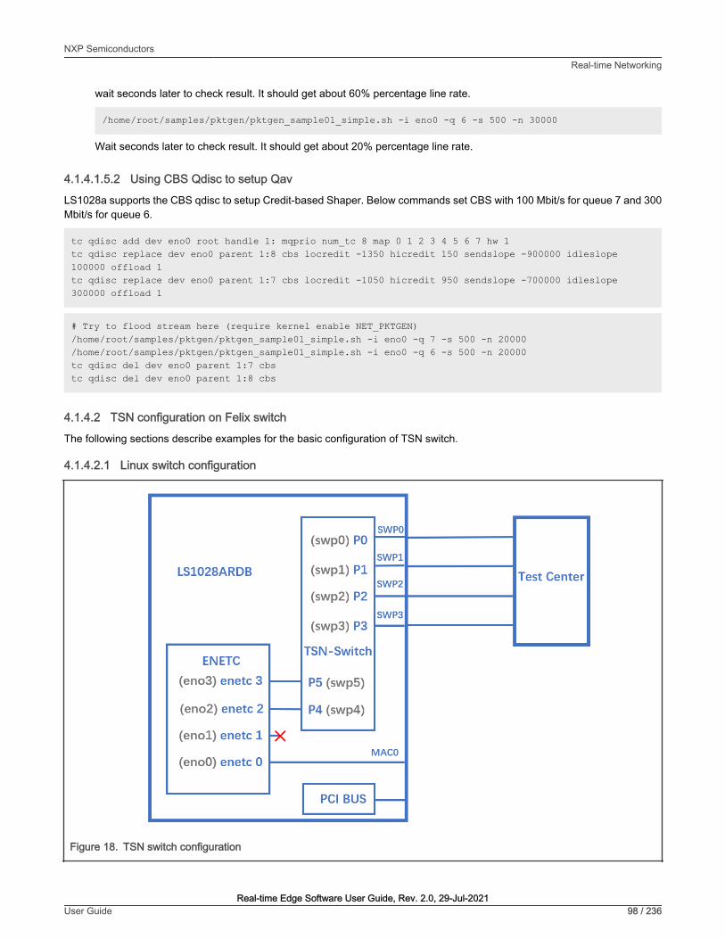
wait seconds later to check result. It should get about 60% percentage line rate.
/home/root/samples/pktgen/pktgen_sample01_simple.sh -i eno0 -q 6 -s 500 -n 30000
Wait seconds later to check result. It should get about 20% percentage line rate.
4.1.4.1.5.2 Using CBS Qdisc to setup Qav
LS1028a supports the CBS qdisc to setup Credit-based Shaper. Below commands set CBS with 100 Mbit/s for queue 7 and 300Mbit/s for queue 6.
tc qdisc add dev eno0 root handle 1: mqprio num_tc 8 map 0 1 2 3 4 5 6 7 hw 1tc qdisc replace dev eno0 parent 1:8 cbs locredit -1350 hicredit 150 sendslope -900000 idleslope 100000 offload 1tc qdisc replace dev eno0 parent 1:7 cbs locredit -1050 hicredit 950 sendslope -700000 idleslope 300000 offload 1
# Try to flood stream here (require kernel enable NET_PKTGEN)/home/root/samples/pktgen/pktgen_sample01_simple.sh -i eno0 -q 7 -s 500 -n 20000/home/root/samples/pktgen/pktgen_sample01_simple.sh -i eno0 -q 6 -s 500 -n 20000tc qdisc del dev eno0 parent 1:7 cbstc qdisc del dev eno0 parent 1:8 cbs
4.1.4.2 TSN configuration on Felix switch
The following sections describe examples for the basic configuration of TSN switch.
4.1.4.2.1 Linux switch configuration
Figure 18. TSN switch configuration
NXP SemiconductorsReal-time Networking
Real-time Edge Software User Guide, Rev. 2.0, 29-Jul-2021User Guide 98 / 236

Note: Test Center is a device to create streams(need 802.1Q Vlan tag) send to LS1028a switch and capture streams forwardedby LS1028a switch.
Use the following commands for configuring the switch on LS1028ARDB:
ls /sys/bus/pci/devices/0000:00:00.5/net/
Get switch device interfaces: swp0 swp1 swp2 swp3>
ifconfig eno2 upip link add name switch type bridgeip link set switch upip link set swp0 master switch && ip link set swp0 upip link set swp1 master switch && ip link set swp1 upip link set swp2 master switch && ip link set swp2 upip link set swp3 master switch && ip link set swp3 up
4.1.4.2.2 Clock synchronization
To test 1588 synchronization on felix-switch interfaces, use the following procedure:
1. Connect two boards back-to-back with switch interfaces. For example, swp0 to swp0.
The Linux booting log is displayed below:
…pps pps0: new PPS source ptp1…
2. Check PTP clock and time stamping capability using the commands below:
$ ethtool -T swp0Time stamping parameters for swp0:Capabilities: hardware-transmit (SOF_TIMESTAMPING_TX_HARDWARE) hardware-receive (SOF_TIMESTAMPING_RX_HARDWARE) hardware-raw-clock (SOF_TIMESTAMPING_RAW_HARDWARE)PTP Hardware Clock: 1Hardware Transmit Timestamp Modes: off (HWTSTAMP_TX_OFF) on (HWTSTAMP_TX_ON) Hardware Receive Filter Modes: none (HWTSTAMP_FILTER_NONE) all (HWTSTAMP_FILTER_ALL)
3. Set switch ip on two board, and ping each other.
$ ifconfig switch 192.168.1.2 /* On board A */$ ifconfig switch 192.168.1.3 /* On board B */$ ping 192.168.1.3 /* On board A */
4. For 802.1AS testing, use the configuration file gPTP.cfg in linuxptp source. Run the below commands on the twoboards instead.
$ ptp4l -i swp0 -p /dev/ptp1 -f /etc/ptp4l_cfg/gPTP.cfg -2 -m
Or use GenAVB/TSN Stack with the following command: 'avb.sh start'. Note that the configuration file /etc/genavb/fgptp-br.cfg is automatically used.
NXP SemiconductorsReal-time Networking
Real-time Edge Software User Guide, Rev. 2.0, 29-Jul-2021User Guide 99 / 236

Note: Clock synchronization must be run before Qbv is set. If Qbv is running, users Should disable and reconfigure Qbv afterclock synchronization.
4.1.4.2.3 Qbv test setup for LS1028ARDB
The following figure describes the setup for Qbv test on LS1028ARDB.
Figure 19. Qbv test
4.1.4.2.3.1 Tsntool usage
4.1.4.2.3.1.1 Closing basic gatesUse the set of commands below for basic gate closing.
echo “t0 00000000b 20000” > qbv0.txt#Explaination:# 'NUMBER' : t0# 'GATE_VALUE' : 00000000b# 'TIME_LONG' : 20000 ns
./tsntooltsntool> verbosetsntool> qbvset --device swp1 --entryfile ./qbv0.txt
#Send one broadcast frame to swp0 from TestCenter.ethtool -S swp1#Should not get any frame from swp1 on TestCenter.
echo “t0 11111111b 20000” > qbv0.txttsntool> qbvset --device swp1 --entryfile ./qbv0.txt
NXP SemiconductorsReal-time Networking
Real-time Edge Software User Guide, Rev. 2.0, 29-Jul-2021User Guide 100 / 236

#Send one broadcast frame to swp0 on TestCenter.ethtool -S swp1#Should get one frame from swp1 on TestCenter.
4.1.4.2.3.1.2 Basetime testFor the basetime test, first get the current second time:
#Get current time: tsntool> ptptool -g -d /dev/ptp1
#add some seconds, for example user gets 200.666 time clock, then set 260.666 as resulttsntool> qbvset --device swp1 --entryfile ./qbv0.txt --basetime 260.666
#Send one broadcast frame to swp0 on the Test Center.#Frame could not pass swp1 until time offset.
4.1.4.2.3.1.3 Qbv performance testUse the following commands for the QBv performance test:
cat > qbv5.txt << EOFt0 11111111b 1000000t1 00000000b 1000000EOFqbvset --device swp1 --entryfile qbv5.txt
#Send 1G rate stream to swp0 on TestCenter.
#The stream would get about half line rate from swp1.
4.1.4.2.3.2 Tc-taprio usage
LS1028ARDB supports the tarprio qdisc to setup Qbv either. Below is an example setup.
1. Enable the Qbv for swp1 port, set queue 1 gate open, set circle time to be 300 µs.
tc qdisc replace dev swp1 parent root handle 100 taprio num_tc 8 map 0 1 2 3 4 5 6 7 \ queues 1@0 1@1 1@2 1@3 1@4 1@5 1@6 1@7 base-time 0 sched-entry S 02 300000 flags 0x2
Since the hardware can only use PCP, DSCP or other methods to classify Qos, it cannot map Qos to differenthardware queues. mqprio is not implemented in the felix driver, so "map 0 1 2 3 4 5 6 7" in the tc-taprio commandis invalid.
NOTE
2. Send one frame with PCP=1 in vlan tag to swp0 from TestCenter, we will capture the frame from swp1.
3. Send one frame with PCP=2 in vlan tag to swp0 from TestCenter, gate is closed and we couldn't capture the frame from swp1.
4. Disable the Qbv for swp1 port as below
tc qdisc del dev swp1 parent root handle 100 taprio
4.1.4.2.4 Qbu
The figure below illustrates the setup for performing the Qbu test using the TSN switch.
NXP SemiconductorsReal-time Networking
Real-time Edge Software User Guide, Rev. 2.0, 29-Jul-2021User Guide 101 / 236

Figure 20. Qbu test on switch
4.1.4.2.4.1 Tsntool usage
1. Set queue 1 to be preemptable. There are two ways to set preemptable queues, users can choose tsntool or ethtool toset it.
#tsntool command to set preemptable queues:tsntool> qbuset --device swp3 --preemptable 0x02
2. Send two streams from TestCenter, set packet size to be 1500Byte and bandwidth to be 1G, then check the number ofadditional mPackets transmitted by PMAC:
ethtool -S swp3 | grep tx_merge_fragments
3. Qbu combined with Qbv test.
Set queue 0 gate open 20us, queue 1 gate open 20us.
cat > qbv0.txt << EOFt0 00000001b 200000t1 00000010b 200000EOFqbvset --device swp3 --entryfile qbv0.txt
Send two streams from TestCenter, packets in queue 1 will be preempted when gate 1 closed
NXP SemiconductorsReal-time Networking
Real-time Edge Software User Guide, Rev. 2.0, 29-Jul-2021User Guide 102 / 236

4.1.4.2.4.2 Ethtool usage
1. Set queue 1 to be preemptable. There are two ways to set preemptable queues, users can choose tsntool or ethtool toset it.
#ethtool command to set preemptable queues:ethtool --set-frame-preemption swp3 preemptible-queues-mask 0x02 min-frag-size 124
Explanation:
• preemptible-queues-mask: A 8-bit vector which specifies preemptable queues within the 8 priorities (with bit-0 forpriority-0 and bit-7 for priority-7).
• min-frag-size: at least frame bytes have been transmitted in fragment, the minimum non-final fragment size is 64,128, 192, or 256 octets (include 4 Bytes fragment header).
2. Send two streams from TestCenter, set packet size to be 1500Byte and bandwidth to be 1G, then check the number ofadditional mPackets transmitted by PMAC:
ethtool -S swp3 | grep tx_merge_fragments
3. Qbu combined with Qbv test.
Set queue 0 gate open 20us, queue 1 gate open 20us.
tc qdisc replace dev swp3 parent root handle 100 taprio num_tc 8 map 0 1 2 3 4 5 6 7 \ queues 1@0 1@1 1@2 1@3 1@4 1@5 1@6 1@7 base-time 0 \ sched-entry S 01 200000 \ sched-entry S 02 200000 flags 0x2
Send two streams from TestCenter, packets in queue 1 will be preempted when gate 1 closed
4.1.4.2.5 Qci
The figure below illustrates the Qci test case setup.
NXP SemiconductorsReal-time Networking
Real-time Edge Software User Guide, Rev. 2.0, 29-Jul-2021User Guide 103 / 236

Figure 21. Qci test case
4.1.4.2.5.1 Tsntool usage
4.1.4.2.5.1.1 Stream identificationUse the following commands for stream identification:
1. Set a stream to swp0 on TestCenter. Edit the stream, set the destination MAC as: 00:01:83:fe:12:01, Vlan ID : 1
2. Add the MAC to MAC table on LS1028a. (This step is not needed if the mac is already learned on port)
bridge fdb add 00:01:83:fe:12:01 dev swp1 vlan 1
3. Use the destination MAC as: 00:01:83:fe:12:01, Vlan ID : 1 to set the stream identification on LS1028a.
tsntool> cbstreamidset --device swp1 --nullstreamid --index 1 --nulldmac 0x000183fe1201 --nullvid 1 --streamhandle 1
Explanation:
• device: set the device port which is the stream forwarded to. If the {destmac, VID} is already learned by switch, switchwill not care device port.
• nulltagged: switch only support nulltagged=1 mode, so there is no need to set it.
NXP SemiconductorsReal-time Networking
Real-time Edge Software User Guide, Rev. 2.0, 29-Jul-2021User Guide 104 / 236

• nullvid: Use "bridge vlan show" to see the ingress VID of switch port.
tsntool> qcisfiset --device swp0 --index 1 --streamhandle 1 --gateid 1 --priority 0 --flowmeterid 68
Explanation:
• device: can be any one of switch ports.
• index: value is the same as streamhandle of cbstreamidset.
• streamhandle: value is the same as streamhandle of cbstreamidset.
• flowmeterid: PSFP Policer id, ranges from 63 to 383.
4. Send one frame, then check the frames.
ethtool -S swp1 ethtool -S swp2
Only swp1 can get the frame.
5. Use the following command to check and debug the stream identification status.
qcisfiget --device swp0 --index 1
The parameter streamhandle is the same as index in stream filter set, we use streamhandle as SFID toidentify the stream, and use index to set stream filter table entry.
NOTE
4.1.4.2.5.1.2 Stream gate control1. Use the following commands for stream gate control:
echo "t0 1b 3 50000 200" > sgi.txttsntool> qcisgiset --device swp0 --enable --index 1 --initgate 1 --initipv 0 --gatelistfile sgi.txt --basetime 0x0
Explanation:
• 'device': can be any one of switch ports.
• 'index': gateid
• 'basetime': It is the same as Qbv set.
2. Send one frame on TestCenter.
ethtool -S swp1
Note that the frame could pass, and green_prio_3 has increased.
3. Now run the following commands:
echo "t0 0b 3 50000 200" > sgi.txtxtsntool> qcisgiset --device swp0 --enable --index 1 --initgate 1 --initipv 0 --gatelistfile sgi.txt --basetime 0x0
4. Next, send one frame on TestCenter.
ethtool -S swp1
NXP SemiconductorsReal-time Networking
Real-time Edge Software User Guide, Rev. 2.0, 29-Jul-2021User Guide 105 / 236

Note that the frame could not pass.
4.1.4.2.5.1.3 SFI maxSDU testUse the following command to run this test:
tsntool> qcisfiset --device swp0 --index 1 --gateid 1 --priority 0 --flowmeterid 68 --maxsdu 200
Now, send one frame (frame size > 200) on TestCenter.
ethtool -S swp1
Users can observe that the frame could not pass.
4.1.4.2.5.1.4 FMI testUse the following set of commands for the FMI test.
1. Run the command:
tsntool> qcifmiset --device swp0 --index 68 --cir 100000 --cbs 4000 --ebs 4000 --eir 100000
• The 'device' in above command can be any one of the switch ports.
• The index of qcifmiset must be the same as flowmeterid of qcisfiset.
NOTE
2. Now, send one stream (rate = 100M) on TestCenter.
ethtool -S swp0
Note that all frames pass and get all green frames.
3. Now, send one stream (rate = 200M) on TestCenter.
ethtool -S swp0
Observe that all frames pass and get green and yellow frames.
4. Send one stream (rate = 300M) on TestCenter.
ethtool -S swp0
Note that not all frames could pass and get green, yellow, and red frames.
5. Send one yellow stream (rate = 100M) on TestCenter.
ethtool -S swp0
All frames pass and get all yellow frames.
6. Send one yellow stream (rate = 200M) on TestCenter.
ethtool -S swp0
Note that not all frames could pass and get yellow and red frames.
7. Test cf mode.
tsntool> qcifmiset --device swp0 --index 68 --cir 100000 --cbs 4000 --ebs 4000 --eir 100000 --cf
NXP SemiconductorsReal-time Networking
Real-time Edge Software User Guide, Rev. 2.0, 29-Jul-2021User Guide 106 / 236

8. Send one yellow stream (rate = 200M) on TestCenter.
ethtool -S swp0
All frames pass and get all yellow frames (use CIR as well as EIR).
9. Send one yellow stream (rate = 300M) on TestCenter.
ethtool -S swp0
Note that not all frames could pass and get yellow and red frames.
4.1.4.2.5.1.5 Port based SFI setLS1028A switch can work on port based PSFP set. This implies that when a null-identified stream is received on an ingress port,switch will use the port, default SFI.
Below example tests no streamhandle in qcisfiset to set a port, default SFI.
1. Use SFID 2 to set swp0 port as default SFI.
tsntool> qcisfiset --device swp0 --index 2 --gateid 1 --flowmeterid 68
After the port default SFI set, any stream sent from swp0 port will do the gate 1 and flowmeter 68 policy.
2. Set stream gate control.
echo "t0 1b 4 50000 200" > sgi.txttsntool> qcisgiset --device swp0 --enable --index 1 --initgate 1 --initipv 0 --gatelistfile sgi.txt
3. Send any stream to swp0.
ethtool -S swp1
Note that the frame could pass, and green_prio_4 has increased.
4.1.4.2.5.2 Tc-flower usage
The figure below illustrates the tc-flower based Qci test case setup.
NXP SemiconductorsReal-time Networking
Real-time Edge Software User Guide, Rev. 2.0, 29-Jul-2021User Guide 107 / 236

Figure 22. TC-flower based Qci test case
1. Get destination MAC on LS1028ARDB board, then use "dst_mac CA:9C:00:BC:6D:68" as shown in the following commands.
ifconfig eno0Link encap:Ethernet HWaddr CA:9C:00:BC:6D:68 inet addr:169.254.88.50 Bcast:169.254.255.255 Mask:255.255.0.0 inet6 addr: fe80::ed36:c4ce:bb04:863d/64 Scope:Link UP BROADCAST RUNNING MULTICAST MTU:1500 Metric:1 RX packets:2 errors:0 dropped:0 overruns:0 frame:0 TX packets:1529 errors:0 dropped:0 overruns:0 carrier:0 collisions:0 txqueuelen:1000 RX bytes:152 (152.0 B) TX bytes:118456 (115.6 KiB)
2. Set Qci on ingress port swp0.
a) Use the following commands to set Qci gate.
tc qdisc add dev swp0 ingresstc filter add dev swp0 chain 30000 protocol 802.1Q parent ffff: flower skip_sw dst_mac CA:9C:00:BC:6D:68 vlan_id 1 action gate index 1 base-time 0 sched-entry CLOSE 6000 -1 -1
NXP SemiconductorsReal-time Networking
Real-time Edge Software User Guide, Rev. 2.0, 29-Jul-2021User Guide 108 / 236

b). Use the following commands to set Qci flow meter.
tc qdisc add dev swp0 ingresstc filter add dev swp0 chain 30000 protocol 802.1Q parent ffff: flower skip_sw dst_mac CA:9C:00:BC:6D:68 vlan_id 1 action police index 1 rate 10Mbit burst 10000
c). Use the following commands to set Qci SFI priority.
tc qdisc add dev swp0 ingresstc filter add dev swp0 chain 30000 protocol 802.1Q parent ffff: flower skip_sw dst_mac CA:9C:00:BC:6D:68 vlan_id 1 vlan_prio 1 action gate index 1 base-time 0 sched-entry CLOSE 6000 -1 -1
d). Use the following commands to set both gate and flow meter.
tc qdisc add dev swp0 ingresstc filter add dev swp0 chain 30000 protocol 802.1Q parent ffff: flower skip_sw dst_mac CA:9C:00:BC:6D:68 vlan_id 1 action gate index 1 base-time 0 sched-entry OPEN 6000 2 -1 action police index 1 rate 10Mbit burst 10000
3. Send a stream from testcenter, set the stream destination mac as CA:9C:00:BC:6D:68, set vid=1 and vlan_prio=1 in thevlan tag.
4. Using "tcpdump -i eno0 -w eno0.pcap" to receive the stream on eno0, check if packets are received.
5. Use the following commands to delete a stream rule.
tc -s filter show dev swp0 ingress chain 30000tc filter del dev swp0 ingress chain 30000 pref 49152
• Each stream can only be added only once. If a user wants to update it, delete the rule and add a new one.
• MAC and VID of stream must have been learned in switch MAC table if the stream is required to be added.
• Qci gate cycle time is expected to be more than 5 μs.
• Qci flow meter can only set cir and cbs now, and the policers are shared with ACL VCAPs.
NOTE
4.1.4.2.6 Qav
The below figure illustrates the Qav test case setup.
NXP SemiconductorsReal-time Networking
Real-time Edge Software User Guide, Rev. 2.0, 29-Jul-2021User Guide 109 / 236

Figure 23. Qav test case
4.1.4.2.6.1 Tsntool usage
1. Set the percentage of two traffic classes:
tsntool> cbsset --device swp2 --tc 1 --percentage 20tsntool> cbsset --device swp2 --tc 2 --percentage 40
2. Send two streams from Test center, then check the frames count.
ethtool -S swp2
Note that the frame count of queue1 is half of queue2.
Stream rate must lager than bandwidth limited of queue.
NOTE
3. Capture frames on swp2 on TestCenter.
# The Get Frame sequence is: (PCP=1), (PCP=2), (PCP=2), (PCP=1), (PCP=2), (PCP=2),…
4.1.4.2.6.2 Tc-cbs usage
LS1028A supports the CBS qdisc to setup Credit-based Shaper. The below commands set CBS with 20 Mbit/s for queue 1 and40 Mbit/s for queue 2.
NXP SemiconductorsReal-time Networking
Real-time Edge Software User Guide, Rev. 2.0, 29-Jul-2021User Guide 110 / 236

1. Set the cbs of two traffic classes:
tc qdisc add dev swp2 root handle 1: mqprio num_tc 8 map 0 1 2 3 4 5 6 7 \ queues 1@0 1@1 1@2 1@3 1@4 1@5 1@6 1@7 hw 0tc qdisc replace dev swp2 parent 1:2 cbs locredit -1470 hicredit 30 \ sendslope -980000 idleslope 20000 offload 1tc qdisc replace dev swp2 parent 1:3 cbs locredit -1440 hicredit 60 \ sendslope -960000 idleslope 40000 offload 1
2. Send one stream with PCP=1 from TestCenter, we can get the stream bandwith is 20 Mbit/s from swp2.
3. Send two streams from Test center, then check the frames count.
ethtool -S swp2
The frame count of queue1 is half of queue2.
NOTE
4. Delete the cbs rules.
tc qdisc del dev swp2 parent 1:2 cbstc qdisc del dev swp2 parent 1:3 cbs
4.1.4.2.7 802.1CB
The following figure describes the test setup for the seamless redundancy test case.
Figure 24. Seamless redundancy test
4.1.4.2.7.1 Sequence Generator test
Use the following set of commands for the 'Sequence Generator' test.
1. Configure switch ports to be forward mode.
On board A:
ifconfig eno2 upip link add name switch type bridge vlan_filtering 1ip link set switch up
NXP SemiconductorsReal-time Networking
Real-time Edge Software User Guide, Rev. 2.0, 29-Jul-2021User Guide 111 / 236

ip link set swp0 master switch && ip link set swp0 upip link set swp1 upip link set swp2 master switch && ip link set swp2 upip link set swp3 master switch && ip link set swp3 upbridge vlan add dev swp0 vid 1 pvidbridge vlan add dev swp2 vid 1 pvidbridge vlan add dev swp3 vid 1 pvid
On board B
ifconfig eno2 upip link add name switch type bridge vlan_filtering 1ip link set switch upip link set swp0 master switch && ip link set swp0 upip link set swp1 master switch && ip link set swp1 upip link set swp2 master switch && ip link set swp2 upip link set swp3 master switch && ip link set swp3 upbridge vlan add dev swp0 vid 1 pvidbridge vlan add dev swp1 vid 1 pvidbridge vlan add dev swp2 vid 1 pvidbridge vlan add dev swp3 vid 1 pvid
2. On board A, run the commands:
bridge fdb add 7E:A8:8C:9B:41:DD dev swp0 vlan 1tsntool> cbstreamidset --device swp0 --index 1 --nullstreamid --nulldmac 0x7EA88C9B41DD --nullvid 1 --streamhandle 1tsntool> cbgen --device swp3 --index 1 --iport_mask 0x08 --split_mask 0x07 --seq_len 16 --seq_num 2048
In the command above,
• device: can be any one of switch ports.
• index: value is the same as streamhandle of cbstreamidset.
3. Send a stream from TestCenter to swp3 of board A, set destination mac as 7E:A8:8C:9B:41:DD.
4. Capture frames on swp2 on TestCenter.
We can get frames from swp2 on TestCenter, each frame adds the sequence number: 23450801, 23450802, 23450803…
5. Capture frames from swp2 of board B on TestCenter, we can get the same frames.
4.1.4.2.7.2 Sequence Recover test
Use the following steps for the Sequence Recover test:
1. On board B, run the following commands:
bridge fdb add 7E:A8:8C:9B:41:DD dev swp2 vlan 1tsntool> cbstreamidset --device swp2 --index 1 --nullstreamid --nulldmac 0x7EA88C9B41DD --nullvid 1 --streamhandle 1tsntool> cbrec --device swp0 --index 1 --seq_len 16 --his_len 31 --rtag_pop_en
In the cbrec command mentioned above:
• device: can be any one of switch ports.
• index: value is the same as streamhandle of cbstreamidset.
2. Send a frame from TestCenter to swp3 of board A, set dest mac to be 7E:A8:8C:9B:41:DD.
3. Capture frames from swp2 of board B on TestCenter, we can get only one frame without sequence tag.
NXP SemiconductorsReal-time Networking
Real-time Edge Software User Guide, Rev. 2.0, 29-Jul-2021User Guide 112 / 236

4.1.4.2.8 TSN stream identification
TSN module uses QoS class to identify and control streams. There are three ways to identify the stream to different QoS class.These are explained in the following sections.
4.1.4.2.8.1 Stream identification based on PCP value of Vlan tag
The default QoS class is based on PCP of Vlan tag for a frame. If there is no Vlan tag for a frame, the default QoS class is 0.
Set the PCP value on TestCenter.
Figure 25. Using PCP value of Vlan tag
4.1.4.2.8.2 Based on DSCP of ToS tag
Use the below steps to identify stream based on DSCP value of ToS tag.
1. Map the DSCP value to a specific QoS class using the command below:
tsntool> dscpset --device swp0 --index 1 --cos 1 --dpl 0
NXP SemiconductorsReal-time Networking
Real-time Edge Software User Guide, Rev. 2.0, 29-Jul-2021User Guide 113 / 236

Explanation:
• index: DSCP value of stream, 0-63.
• cos: QoS class which is mapped to.
• dpl: Drop level which is mapped to.
2. Set the DSCP value on TestCenter. DSCP value is the upper six bits of ToS in IP header, set the DSCP value on TestCenteras shown in the following figure.
Figure 26. Setting DSCP value on TestCenter
4.1.4.2.8.3 Based on qci stream identification
The following steps describe how to use qci to identify the stream and set it to a QoS class.
NXP SemiconductorsReal-time Networking
Real-time Edge Software User Guide, Rev. 2.0, 29-Jul-2021User Guide 114 / 236

1. Identify a stream.
tsntool> cbstreamidset --device swp1 --nullstreamid --nulldmac 0x000183fe1201 --nullvid 1 --streamhandle 1tsntool> qcisfiset --device swp0 --index 1 --gateid 1 --flowmeterid 68
2. Set to Qos class 3 by using stream gate control.
echo "t0 1b 3 50000 200" > sgi.txttsntool> qcisgiset --device swp0 --enable --index 1 --initgate 1 --initipv 0 --gatelistfile sgi.txt
The Qci-based identity stream can only be used on both the ingress and egress are bridge ports. The flow injectedor extracted through the CPU port cannot be configured for Qci.
NOTE
4.1.5 TSN on LS1021A-TSNOn the LS1021A-TSN platform, TSN features are provided by the SJA1105TEL Automotive Ethernet switch. These hardwarefeatures comply to pre-standard (draft) versions of the following IEEE specifications:
• 802.1Qbv - Time Aware Shaping
• 802.1Qci - Per-Stream Filtering and Policing
• 1588v2 - Precision Time Protocol
The following demonstration illustrates the SJA1105 hardware features listed below:
• Ingress rate limiting via the L2 (best-effort) policers
• Time-aware shaping
• 802.1AS gPTP synchronization
4.1.5.1 Topology
For demonstrating the SJA1105 TSN features, the following topology is required:
• 1 LS1021A-TSN board, acting as a TSN switch
• 1 generic host (can be a PC or another board) capable of PTP hardware timestamping, acting as a sender of latency-sensitive traffic
• 1 generic host (can be a PC or another board), acting as a sender of high-bandwidth traffic
• 1 generic host (can be a PC or another board) capable of PTP hardware timestamping, acting as receiver for thelatency-sensitive and for the high-bandwidth traffic
The required software packages for the generic hosts are:
• ptp4l, phc2sys and phc_ctl from the linuxptp package: https://sourceforge.net/projects/linuxptp/files/v3.1/linuxptp-3.1.tgz
• iperf3
• isochron from the tsn-scripts package: https://github.com/vladimiroltean/tsn-scripts/tree/isochron
The generic hosts are assumed to be connected to the LS1021A-TSN board through an interface called eth0.
This topology is depicted in the following figure.
NXP SemiconductorsReal-time Networking
Real-time Edge Software User Guide, Rev. 2.0, 29-Jul-2021User Guide 115 / 236

Figure 27. Topology of the demo network
4.1.5.2 SJA1105 Linux support
The SJA1105 switch is supported in the Real-time Edge Linux kernel using the Distributed Switch Architecture (DSA) framework(an overview of which can be found at https://netdevconf.info/2.1/papers/distributed-switch-architecture.pdf).
The following kernel configuration options are available for controlling its features:
• CONFIG_NET_DSA_SJA1105: enables base support for probing the SJA1105 ports as 4 standalone net devices capable ofsending and receiving traffic
• CONFIG_NET_DSA_SJA1105_PTP: enables additional support for the PTP Hardware Clock (PHC), visible in /dev/ptp1 onthe LS1021A-TSN board, and for PTP timestamping on the SJA1105 ports
• CONFIG_NET_DSA_SJA1105_TAS: enables additional support for the Time-Aware Scheduler (TAS), which is configured viathe tc-taprio qdisc offload
The documentation for this kernel driver is available at https://www.kernel.org/doc/html/latest/networking/dsa/sja1105.html.Below is a listing of several driver features.
NXP SemiconductorsReal-time Networking
Real-time Edge Software User Guide, Rev. 2.0, 29-Jul-2021User Guide 116 / 236
The LS1021A-TSN device tree (arch/arm/boot/dts/ls1021a-tsn.dts) defines the sja1105 port names as swp2, swp3, swp4 andswp5. The numbers have a direct correspondence with the chassis labels ETH2, ETH3, ETH4 and ETH5. The ETH2 chassis label(represented in Linux by the swp2 net device) should not be confused with the eth2 net device, which represents the LS1021Ahost port for this switch (called DSA master).
On the LS1021A-TSN board, network management is done by the systemd-networkd daemon, whose configuration files arelocated in /etc/systemd/network/. On this board, the following configuration files for systemd-networkd are present by default:
• br0.netdev: Creates a bridge net device with VLAN filtering disabled, STP disabled and MVRP disabled
• br0.network: Configures the net devices enslaved to br0 to request an IPv4 address via DHCP
• eth0.network, eth1.network, swp.network: Configures all 6 ports of the LS1021A-TSN board to be part of the same br0 bridge(4 ports are bridged in hardware, 2 ports are bridged in software)
• eth2.network: Configures the DSA master port to come up automatically, and assigns it a dummy link-local IP address. Havingthe DSA master interface up is a requirement for using the switch net devices.
Although all ports are configured for L2 forwarding by default (and therefore the only IP address for this board should be assignedto br0), this can be changed by removing the "Bridge=br0" line from the files in /etc/systemd/network/ and then running "systemctlrestart systemd-networkd".
In standalone mode, each SJA1105 port is able of acquiring an IP address and transferring general purpose packets to/from thekernel. This is internally supported by the kernel driver by repurposing the VLAN tagging functionality for switch port separationand identification. Therefore the ability to support general purpose traffic I/O only works as long as the user does not requestVLAN tagging, via the bridge vlan_filtering option. When this happens, the switch driver goes to a reduced functionality mode,where the swpN net devices are no longer capable of sending and receiving general packets to/from the kernel. This is a hardwarelimitation which can be somewhat mitigated by enabling the best_effort_vlan_filtering devlink parameter (by following the steps inthe kernel documentation).
Actually there is a second mechanism of frame tagging, which works for STP and PTP traffic and does not rely on VLAN tagging.Therefore, the STP and PTP protocols remain operational on the sja1105 driver even when the ports are enslaved to a bridgewith vlan_filtering=1.
When VLAN awareness is disabled, the sja1105 ports perform no checks on VLAN port membership or PCP, and performs noalteration to the VLAN tags. For these operations, the following command is necessary:
ip link set dev br0 type bridge vlan_filtering 1
Once VLAN filtering is enabled, the VLAN table of each switch port can be inspected and modified using the "bridge vlan"commands from the iproute2 package.
The STP state machine can be started on the bridge using the following command:
ip link set dev br0 type bridge stp_state 1ip link set dev br0 downip link set dev br0 up
The switch L2 address forwarding database (FDB) can be inspected and modified using the "bridge fdb" set of commands.
Port statistics counters can be inspected using the ethtool -S swpN command.
The sja1105 port MTU can be configured up to a maximum of 2021 using the following command:
ip link set dev swp2 mtu 2000
Port mirroring on a sja1105 port (mirroring of ingress and/or egress packets) can be configured via the following set of commands:
tc qdisc add dev swp2 clsacttc filter add dev swp2 ingress matchall skip_sw \ action mirred egress mirror dev swp3
NXP SemiconductorsReal-time Networking
Real-time Edge Software User Guide, Rev. 2.0, 29-Jul-2021User Guide 117 / 236

tc filter show dev swp2 ingresstc filter del dev swp2 ingress pref 49152
There are 3 types of policers currently supported by the sja1105 driver:
• Port policers: These affect all traffic that is incoming on a port, except traffic that hits a more specific rule (see below). Theseare configured as follows:
tc qdisc add dev swp2 clsacttc filter add dev swp2 ingress matchall skip_sw \ action police rate 10mbit burst 64k
• Traffic class policers: These affect only traffic having a specific VLAN PCP. To limit traffic with VLAN PCP 0 (also includesuntagged traffic) to 100 Mbit/s on port swp2 only:
tc qdisc add dev swp2 clsacttc filter add dev swp2 ingress protocol 802.1Q flower skip_sw \ vlan_prio 0 action police rate 100mbit burst 64k
• Broadcast policers: These affect only broadcast traffic (destination MAC ff:ff:ff:ff:ff:ff) received on an ingress port.
tc qdisc add dev swp2 clsacttc filter add dev swp2 ingress flower skip_sw dst_mac ff:ff:ff:ff:ff:ff \ action police rate 10mbit burst 64k
In absence of a specific policer allocated to a traffic class or to broadcast traffic, these packets will consume from the bandwidthbudget of the port policer.
It is also possible to combine the bandwidth allocation of a traffic class, or of broadcast traffic on multiple ports, and assign themto a single policer. This functionality is called "shared filter blocks" and can be configured as follows (the example below limitsbroadcast traffic coming from all switch ports to a total of 10 Mbit/s):
tc qdisc add dev swp2 ingress_block 1 clsacttc qdisc add dev swp3 ingress_block 1 clsacttc qdisc add dev swp4 ingress_block 1 clsacttc qdisc add dev swp5 ingress_block 1 clsacttc filter add block 1 flower skip_sw dst_mac ff:ff:ff:ff:ff:ff \ action police rate 10mbit burst 64k
For PTP, the sja1105 driver implements the kernel primitives required for interoperating with the linuxptp and other open sourceapplication stacks. Real-time Edge on the LS1021A-TSN is configured to start linuxptp by default in 802.1AS bridge mode on portsswp2, swp3, swp4 and swp5. The following system components are involved:
• ptp4l: Daemon that implements the IEEE 1588/802.1AS state machines. Configured via the /etc/linuxptp.cfg file andcontrolled via the linuxptp.service systemctl service.
• phc2sys: Daemon that synchronizes the system time (CLOCK_REALTIME) to the active PHC (/dev/ptp1) or viceversa,depending on the board role in the network (PTP master or slave). Configured via the /etc/linuxptp-system-clock.cfg file andcontrolled via the phc2sys.service systemctl service.
To inspect the PTP synchronization status of the board, the following commands can be used:
systemctl start --now ptp4lsystemctl start --now phc2sysjournalctl -b -u ptp4l -fjournalctl -b -u phc2sys -f
Under steady state, the switch ports are expected to maintain a synchronization offset of +/- 100 ns offset to the PTP master.
NXP SemiconductorsReal-time Networking
Real-time Edge Software User Guide, Rev. 2.0, 29-Jul-2021User Guide 118 / 236

During normal operation, the static configuration of the sja1105 needs to be changed by the driver. In turn, this requires a switchreset, which temporarily disrupts Ethernet traffic and PTP synchronization. After a switch reset, the PTP synchronization offsetmay jump to a higher momentary range of +/- 2 500 000 ns. The list of reset reasons in the sja1105 kernel driver is:
• Enabling or disabling VLAN filtering, via the "ip link" command.
• Enabling or disabling PTP timestamping.
• Configuring the ageing time (which is done automatically by the kernel STP state machine when STP is active).
• Configuring the Time-Aware Scheduler via the tc-taprio command.
• Configuring the L2 policers (for MTU or for policing).
4.1.5.3 Synchronized 802.1Qbv demo
The objectives of this demonstration are the following:
• Synchronize the SJA1105 PTP clock using IEEE 802.1AS.
• Run the SJA1105 Time-Aware Scheduler (802.1Qbv engine) based on the PTP clock.
• Create a small switched TSN network with a flow requiring deterministic latency. Prove the latency is not affected byinterfering traffic.
In the topology described earlier in this chapter, the boards which require to be synchronized by PTP are hosts 1, 2 and theLS1021A-TSN board. Host 3 only generates iperf traffic, which is not time-sensitive.
The following commands are required to start PTP synchronization using the 802.1AS profile on host 1 and 2:
ptp4l -i eth0 -f /etc/linuxptp/gPTP.cfg -mphc2sys -a -rr --transportSpecific 0x1 --step_threshold 0.0002 --first_step_threshold 0.0002
Different output is expected on the two hosts. One will become PTP grandmaster and show the following logs:
• ptp4l:
ptp4l[13.067]: port 1: link upptp4l[13.104]: port 1: FAULTY to LISTENING on INIT_COMPLETEptp4l[16.113]: port 1: LISTENING to MASTER on ANNOUNCE_RECEIPT_TIMEOUT_EXPIRESptp4l[16.113]: selected local clock 00049f.fffe.05de06 as best masterptp4l[16.113]: port 1: assuming the grand master roleptp4l[16.692]: port 1: new foreign master 001f7b.fffe.630248-1ptp4l[16.692]: selected best master clock 00049f.fffe.05f627ptp4l[16.692]: port 1: assuming the grand master role
• phc2sys:
phc2sys[73.382]: eno0 sys offset 12 s2 freq +2009 delay 1560phc2sys[74.382]: eno0 sys offset 2 s2 freq +2003 delay 1560phc2sys[75.382]: eno0 sys offset -18 s2 freq +1983 delay 1600phc2sys[76.383]: eno0 sys offset 27 s2 freq +2023 delay 1600phc2sys[77.383]: eno0 sys offset 7 s2 freq +2011 delay 1600phc2sys[78.383]: eno0 sys offset -18 s2 freq +1988 delay 1560phc2sys[79.383]: eno0 sys offset -8 s2 freq +1993 delay 1560
While the other board will become a PTP slave, as seen by the following logs:
• ptp4l:
ptp4l[68484.668]: rms 17 max 36 freq +1613 +/- 15 delay 737 +/- 0 ptp4l[68485.668]: rms 8 max 15 freq +1622 +/- 11 delay 737 +/- 0
NXP SemiconductorsReal-time Networking
Real-time Edge Software User Guide, Rev. 2.0, 29-Jul-2021User Guide 119 / 236

ptp4l[68486.669]: rms 14 max 28 freq +1643 +/- 13 delay 737 +/- 0 ptp4l[68487.670]: rms 11 max 17 freq +1650 +/- 10 delay 738 +/- 0 ptp4l[68488.671]: rms 11 max 20 freq +1633 +/- 15 delay 738 +/- 0 ptp4l[68489.672]: rms 8 max 16 freq +1640 +/- 11 delay 737 +/- 0 ptp4l[68490.673]: rms 16 max 32 freq +1640 +/- 23 delay 737 +/- 0 ptp4l[68491.674]: rms 12 max 21 freq +1622 +/- 13 delay 737 +/- 0 ptp4l[68492.675]: rms 13 max 19 freq +1648 +/- 13 delay 738 +/- 0ptp4l[68493.676]: rms 18 max 34 freq +1668 +/- 15 delay 737 +/- 0
• phc2sys:
phc2sys[68508.790]: CLOCK_REALTIME phc offset 10 s2 freq -342 delay 1600phc2sys[68509.791]: CLOCK_REALTIME phc offset 2 s2 freq -347 delay 1560phc2sys[68510.791]: CLOCK_REALTIME phc offset 9 s2 freq -339 delay 1600phc2sys[68511.791]: CLOCK_REALTIME phc offset -22 s2 freq -368 delay 1560phc2sys[68512.791]: CLOCK_REALTIME phc offset -19 s2 freq -371 delay 1560phc2sys[68513.791]: CLOCK_REALTIME phc offset -13 s2 freq -371 delay 1560phc2sys[68514.791]: CLOCK_REALTIME phc offset 48 s2 freq -314 delay 1560phc2sys[68515.792]: CLOCK_REALTIME phc offset 22 s2 freq -325 delay 1560phc2sys[68516.792]: CLOCK_REALTIME phc offset 17 s2 freq -324 delay 1560phc2sys[68517.792]: CLOCK_REALTIME phc offset -29 s2 freq -365 delay 1560
The role of the LS1021A-TSN board is to relay the PTP time from the 802.1AS grandmaster to the slave. It acts as a slave on theport connected to the GM and as a master on the port connected to the other host.
[root] # journalctl -b -u ptp4l -f-- Logs begin at Tue 2020-04-07 14:02:11 UTC. --ptp4l[86640.528]: rms 10 max 23 freq -19731 +/- 11 delay 737 +/- 0ptp4l[86641.528]: rms 9 max 15 freq -19740 +/- 13 delay 736 +/- 0ptp4l[86642.529]: rms 12 max 19 freq -19757 +/- 10 delay 737 +/- 0ptp4l[86643.530]: rms 9 max 14 freq -19747 +/- 13 delay 737 +/- 0ptp4l[86644.530]: rms 13 max 22 freq -19733 +/- 15 delay 736 +/- 0ptp4l[86645.531]: rms 7 max 14 freq -19735 +/- 9 delay 737 +/- 0ptp4l[86646.532]: rms 7 max 13 freq -19735 +/- 9 delay 737 +/- 0ptp4l[86647.532]: rms 11 max 19 freq -19750 +/- 12 delay 737 +/- 0ptp4l[86648.533]: rms 6 max 14 freq -19745 +/- 8 delay 737 +/- 0ptp4l[86649.534]: rms 9 max 15 freq -19750 +/- 12 delay 736 +/- 0
The above information can be interpreted as follows (only the last line is interpreted here):
• Because the default (implicit) summary_interval in /etc/linuxptp.cfg is 0 (print stats once per second) and the logSyncIntervalrequired by 802.1AS is -3 (the sync messages are sent at an interval of 1/8 seconds - 125 ms), this means that synchronizationstats cannot be printed in full (for each packet) and are printed in an abbreviated form (there is no "offset" in the logs).
• The offset to the master has a root mean square value of 9 ms, with a maximum of 15 ns in the past 1 second.
• The frequency correction required to synchronize to the GM was on average -19750 parts per billion (ppb). If the frequencyadjustment exceeds a certain sanity threshold (depending on kernel driver), ptp4l may print "clockcheck" warnings andstop synchronization. This can be sometimes remedied manually by running the following command to reset the PTP clockfrequency adjustment to zero:
phc_ctl /dev/ptp0 freq 0
NXP SemiconductorsReal-time Networking
Real-time Edge Software User Guide, Rev. 2.0, 29-Jul-2021User Guide 120 / 236

• The measured path delay (MAC to MAC propagation delay for ~70 bytes frames at 1Gbps) between its device and its linkpartner is exactly 736 ns.
The clock distribution tree in this network is as follows: the system clock of the PTP GM (e.g. Host 1) disciplines its PTP hardwareclock (/dev/ptp0), using phc2sys. Over Ethernet, the PTP GM disciplines the SJA1105 PHC, which disciplines the PTP slave (e.g.Host 2). On the slave host, the phc2sys process runs in the reverse direction, disciplining the system clock (CLOCK_REALTIME)to the PTP hardware clock (/dev/ptp0).
A note on using the LS1021A-TSN board as a gPTP GM for this scenario (in place of Host 1). On this board there is nobattery-backed RTC, so there is no persistent source of time onboard. One has to rely on the NTP service (ntpd.service) to providetime, otherwise a time in 1970 will be relayed into the PTP network.
A note on using phc2sys on the slave host. Since phc2sys attempts to discipline CLOCK_REALTIME, one must manually ensurethat other daemons in the system do not attempt to do the same thing, such as ntpd. Otherwise there will be access conflictsbetween phc2sys and the other daemon, and phc2sys will keep printing clockcheck warning messages.
Install the following schedule into the sja1105 port egressing towards Host 2:
tc qdisc add dev swp2 parent root taprio \ num_tc 8 \ map 0 1 2 3 4 5 6 7 \ queues 1@0 1@1 1@2 1@3 1@4 1@5 1@6 1@7 \ base-time 0 \ sched-entry S 80 50000 \ sched-entry S 40 50000 \ sched-entry S 3f 300000 \ flags 2
The base-time of 0 indicates the phase offset of the network schedule. This time corresponds to Jan 1st 1970, but it is automaticallyadvanced into an equivalent time into the immediate PTP future (it is advanced by an integer number of cycle-time nanoseconds).
The cycle-time in this example is not provided explicitly, but it is calculated as the sum of the durations of all gate events: 400microseconds (us).
The schedule at the egress of swp2 is divided as follows:
• 50 us for PTP traffic (S 80). The traffic class assignment of 7 for link-local management traffic (STP, PTP, etc) is fixed to 7 atdriver level and is not user configurable at this time.
• 50 us for traffic class 6 (S 40). The latency-sensitive traffic generator will be injecting into this window.
• 300 us for all other traffic classes 0-5 (S 3f).
Enabling QoS classification on the sja1105 switch based on VLAN PCP is done by running:
ip link set dev br0 type bridge vlan_filtering 1
First the receiver for latency-sensitive traffic needs to be started on Host 2. This process waits for connections from the senderand then transmits its statistics to it.
ip addr add 192.168.1.2/24 dev eth0isochron rcv --interface eth0 --quiet
The sender is started on Host 1 as follows:
ip addr add 192.168.1.1/24 dev eth0isochron send --interface eth0 --dmac 00:04:9f:05:de:06 --priority 6 --vid 0 \ --base-time 0 --cycle-time 400000 --shift-time 50000 --advance-time 90000 \ --num-frames 10000 --frame-size 64 --client 192.168.1.2 --quiet
NXP SemiconductorsReal-time Networking
Real-time Edge Software User Guide, Rev. 2.0, 29-Jul-2021User Guide 121 / 236

The log should look as follows:
Base time 0.000040000 is in the past, winding it into the future Now: 1586282691.751150218 Base time: 1586282691.751160000Cycle time: 0.000400000Collecting receiver statsSummary:Path delay: min 4329 max 4444 mean 4387.987 stddev 24.508HW TX deadline delta: min -65238 max -18938 mean -59707.395 stddev 1371.995SW TX deadline delta: min -33528 max 25058 mean -28221.001 stddev 1844.235HW RX deadline delta: min -60874 max -14529 mean -55319.408 stddev 1372.222SW RX deadline delta: min -43398 max 130659 mean -38212.966 stddev 2514.592HW TX deadline misses: 0 (0.000%)SW TX deadline misses: 1 (0.010%)
The following clarifications are necessary:
• The destination MAC is that of Host 2's interface eth0
• The sent packets have a VLAN tag with VID 0 and PCP 6. Because they are priority-tagged (802.1p) the sja1105 switch portswill accept these packets without any "bridge vlan add vid 0 dev swp3" command.
• The isochron program sends a number of 10000 frames, at an interval of 400 us. The base-time is the same as on thesja1105 egress port swp2, but it is shifted with 50 us to the right, in order to align with the beginning of traffic class 6's window(which is the second timeslot in the schedule). The packet transmission deadlines are therefore at (base-time + shift-time +N * cycle-time).
• Packets must in fact be transmitted earlier than the TX deadline, in order to compensate for scheduling latencies in theLinux kernel and the actual propagation delay of the packet. So the isochron program sleeps until 90 us in advance of thenext deadline.
• By "winding the base time into the future", one understands the process by which the original base time (0) is incrementedby the smallest number N of cycles such that it becomes greater than the current PTP time (1586282691.751150218). In thiscase, the new base-time is 1586282691.751160000.
• For each packet, the sender collects 2 TX timestamps: one hardware and one software. The receiver also collects twotimestamps. These timestamps are not printed to the console because the --quiet option was specified.
• Correlation between timestamps at the sender and at the receiver is done through a secondary socket. The receiver waits forconnections on TCP port 5000, and transmits its log to the sender, which correlates with its own log by using a key formed outof {sequence number, scheduled TX time (deadline)}. Both these values are embedded into the packet payload. If the --clientoption is omitted, the statistics correlation is not performed. This TCP socket is the only reason for which IP communicationis necessary in this network.
• The path delay is calculated as the delta between the RX hardware timestamp at the receiver and the TX hardware timestampat the sender.
• Each "deadline delta" is calculated as the difference between the timestamp and the scheduled TX time of this packet. TheHW TX deadline delta should always be negative, as that indicates the packets were sent before the scheduled TX time hasexpired. The SW TX timestamps are taken after the HW TX timestamps in this case, so their meaning is less relevant for thisdriver. The RX deadline deltas will become relevant once the 802.1Qbv schedule is installed on the sja1105 switch port.
The above log was taken with no 802.1Qbv schedule active on the sja1105 port and no background traffic. After startingbackground traffic:
# Host 2iperf3 -s > /dev/null &sysctl -w kernel.sched_rt_runtime_us=-1chrt --fifo 90 isochron rcv -i eth0 --quiet# Host 3ip addr add 192.168.1.3/24 dev eth0
NXP SemiconductorsReal-time Networking
Real-time Edge Software User Guide, Rev. 2.0, 29-Jul-2021User Guide 122 / 236

iperf3 -c 192.168.1.2 -t 48600Connecting to host 10.0.0.112, port 5201[ 5] local 10.0.0.113 port 60360 connected to 10.0.0.112 port 5201[ ID] Interval Transfer Bitrate Retr Cwnd[ 5] 0.00-1.00 sec 105 MBytes 878 Mbits/sec 0 489 KBytes[ 5] 1.00-2.00 sec 102 MBytes 859 Mbits/sec 0 513 KBytes[ 5] 2.00-3.00 sec 102 MBytes 858 Mbits/sec 0 513 KBytes[ 5] 3.00-4.00 sec 101 MBytes 851 Mbits/sec 0 513 KBytes[ 5] 4.00-5.00 sec 102 MBytes 860 Mbits/sec 0 539 KBytes
a re-run of the isochron traffic generated by Host 1 looks as follows:
chrt --fifo 90 isochron send -i eno0 -d 00:04:9f:05:de:06 -p 6 -v 0 -b 0 -S 50000 -c 400000 -a 90000 -n 10000 -s 64 -C 10.0.0.112 -q Base time 0.000040000 is in the past, winding it into the future Now: 1586286409.635121693 Base time: 1586286409.635160000Cycle time: 0.000400000Collecting receiver statsSummary:Path delay: min 4314 max 16774 mean 9725.688 stddev 3919.150HW TX deadline delta: min -64273 max -8538 mean -59894.931 stddev 1467.284SW TX deadline delta: min -33286 max 37575 mean -28498.114 stddev 2006.546HW RX deadline delta: min -58924 max -904 mean -50169.243 stddev 4183.042SW RX deadline delta: min -52757 max 1109472 mean -29436.032 stddev 23537.847HW TX deadline misses: 0 (0.000%)SW TX deadline misses: 4 (0.040%)
It can be seen that the path delay variance has increased due to the prolonged wait of packets until MTU-sized packets generatedby iperf3 have finished transmission.
Finally, installing the 802.1Qbv schedule on the switch has effects upon all statistics calculated by isochron:
chrt --fifo 90 isochron send -i eno0 -d 00:04:9f:05:de:06 -p 6 -v 0 -b 0 -S 50000 -c 400000 -a 90000 -n 10000 -s 64 -C 10.0.0.112 -q Base time 0.000040000 is in the past, winding it into the future Now: 1586286689.223100936 Base time: 1586286689.223160000Cycle time: 0.000400000Collecting receiver statsSummary:Path delay: min 14199 max 65684 mean 61357.368 stddev 1494.831HW TX deadline delta: min -64128 max -12643 mean -59822.445 stddev 1494.557SW TX deadline delta: min -33616 max 25621 mean -28448.709 stddev 1974.185HW RX deadline delta: min 1476 max 2041 mean 1534.924 stddev 24.822SW RX deadline delta: min 5243 max 1122800 mean 21040.814 stddev 16752.155HW TX deadline misses: 0 (0.000%)SW TX deadline misses: 5 (0.050%)
The path delay has increased, but that is because now it contains the time spent by the packets blocked on the switch waiting forgate 6 to open.
The HW RX deadline delta now has a new meaning, since in the last example (with 802.1Qbv enabled on the switch), the gateacts as a barrier and eliminates the jitter in HW TX timestamps, which is induced by scheduling latencies in the sender's operatingsystem. Generally speaking, the jitter of the sender is eliminated by the first switch upon packet admission into the TSN network.The effect is that the receiver sees a packet stream with low jitter.
The path delay can be reduced by decreasing the advance time. It is configured in such a way that the packets arrive on theswitch prior to the gate opening, which depends on the jitter of the sender. Minimizing the TX jitter is outside the scope ofthis demonstration.
NXP SemiconductorsReal-time Networking
Real-time Edge Software User Guide, Rev. 2.0, 29-Jul-2021User Guide 123 / 236

4.2 GenAVB/TSN stack
4.2.1 IntroductionThe GenAVB/TSN Stack provides advanced implementation for Audio Video Bridging (AVB) and Time-Sensitive Networking(TSN) functionalities on NXP SoCs and hardware platforms. These functions require TSN hardware support, available in theLS1028A and i.MX 8M Plus SoC.
This section provides information on how to set up and evaluate the GenAVB/TSN Stack. In that context, it provides informationon supported SoCs and boards, compile time software package configuration, and runtime configuration settings.
4.2.1.1 gPTP stack
The gPTP stack implements IEEE 802.1AS-2020 standard, and supports both time-aware Endpoint and Bridge systems. Thestack runs fully in userspace, using Linux socket API’s for packet transmit, receive and timestamping. Linux clock API’s are usedfor clock adjustment. Configuration files are used to configure the stack at initialization time and extensive logging is available atrun time.
4.2.1.2 SRP stack
The SRP stack implements MRP, MVRP and MSRP defined in IEEE 802.1Q-2018, sections 10, 11 and 35. The stack runs fullyin userspace, using Linux socket API’s for packet transmit and receive. Linux tc and bridge netlink API's are used to updateMulticast FDB entries and FQTSS Credit Based Shaper (CBS) configuration. Configuration files are used to configure the stackat initialization time and extensive logging is available at run time.
4.2.1.3 TSN Endpoint example application
The TSN example application provides example code and re-usable middleware exercising the GenAVB/TSN API. It is used toexercise and verify the real time behavior of the local system as well as TSN properties of the network between endpoints.
Figure 28. TSN application cycle
The TSN example application implements a control loop similar to industrial use cases requiring cyclic isochronous exchangesover the network.
NXP SemiconductorsReal-time Networking
Real-time Edge Software User Guide, Rev. 2.0, 29-Jul-2021User Guide 124 / 236

The TSN endpoints run their application synchronized to a common time grid in the same gPTP domain so that they can send andreceive network traffic in a cyclic isochronous pattern (the application cycle time is equal and synchronous to the network cycletime as shown in above figure). Currently the cycle is configured with a period of 2ms. When the application is scheduled, framesfrom other endpoints are ready to be read and at the end of the application time frames are sent to other endpoints.
Figure 29. TSN application scheduling
As shown in the figure above, the controller and the IO devices are scheduled with a half cycle offset in order to reduce theprocessing latency.
The time sensitive traffic is layer 2 multicast with VLAN header and proprietary EtherType. Its priority is defined using the PCPfield of the VLAN header.
In addition, the TSN application provides detailed logs and time sensitive traffic timing statistics (based on hardware timestampingof packets) which allow characterization of an entire real time distributed system.
Finally, a OPCUA server is implemented and offer the possibility to browse and retrieve the TSN application statistics exposedas OPCUA objects. The OPCUA server runs over TCP and allows access to any OPCUA client.
4.2.1.4 Supported configurations
GenAVB/TSN Stack currently supports the following boards and the associated roles:
• LS1028ARDB: gPTP Time-aware Bridge and SRP Bridge
• i.MX 8M Plus EVK: gPTP Time-aware Endpoint station and TSN Endpoint example application
The stack supports and is enabled in the following Yocto Real-time Edge machines:
• imx8mpevk
• ls1028ardb
4.2.2 Building the image through YoctoGenAVB/TSN package genavb-tsn, is included by default in the Yocto Real-time Edge image nxp-real-time-edge whenbuilding for the following machines:
• imx8mpevk
• ls1028ardb
Follow Real-time Edge Software Yocto Project to get the code and setup the build environment.
NXP SemiconductorsReal-time Networking
Real-time Edge Software User Guide, Rev. 2.0, 29-Jul-2021User Guide 125 / 236

Run the following commands to build the images for these machines:
$ cd yocto-real-time-edge
For LS1028ARDB image:
$ DISTRO=nxp-real-time-edge MACHINE=ls1028ardb source real-time-edge-setup-env.sh -b build-ls1028ardb
For i.MX 8M Plus EVK image:
$ DISTRO=nxp-real-time-edge MACHINE=imx8mpevk source real-time-edge-setup-env.sh -b build-imx8mpevk
Then, use:
$ bitbake nxp-image-real-time-edge
4.2.3 GenAVB/TSN stack start/stopGenAVB/TSN stack can be manually started/stopped at run time by using the following commands:
# avb.sh <start|stop>
This will start all stack components and example application. The stack can be automatically started during system startup, bysetting the variable CFG_AUTO_START to 1 in the file /etc/genavb/config.
To just start/stop the gPTP stack use:
# fgptp.sh <start|stop>
4.2.4 Use cases description
4.2.4.1 gPTP Bridge
LS1028ARDB can be used as a generic time-aware bridge, connected to other time-aware end stations or bridges.
By default, LS1028ARDB does not forward packets if no bridge interface is configured under Linux. Enabling bridge interfaceis dependent on the board used. For example, how to configure bridge interface on LS1028ARDB is described in section Linuxswitch configuration.
Once gPTP stack is started, logs can be displayed with the following command:
# tail –f /var/log/fgptp-br
In this log file, one can observe which ports are connected, which ports are currently communicating a synchronized time and whatis the role of the port in the time-aware system.
If a port of the bridge is connected to another port capable of communicating a synchronized time, the following log should appearfor each enabled gPTP domain:
gptp_stats_dump : Port(1) domain(0,0): Role: Master Link: Up asCapable: Yes neighborGptpCapable: Yes...gptp_stats_dump : Port(1) domain(1,20): Role: Master Link: Up asCapable: Yes neighborGptpCapable: Yes
Role status can also take the value Slave depending on parameters described in section Grandmaster parameters.
If a port is not connected, Link status takes the value Down.
If a port is not capable of communicating a synchronized time, AS_Capable status takes the value No.
NXP SemiconductorsReal-time Networking
Real-time Edge Software User Guide, Rev. 2.0, 29-Jul-2021User Guide 126 / 236

For further details about gPTP logs, refer to section gPTP Bridge.
4.2.4.2 gPTP Endpoint
Once gPTP stack is started, logs can be displayed with the following command:
# tail –f /var/log/fgptp
In this log file, one can observe the role of the port in the time-aware system.
If the port of the endpoint is connected to another port capable of communicating a synchronized time, the following log shouldappear for each gPTP domain:
gptp_stats_dump : Port(0) domain(0,0): Role: Slave Link: Up AS_Capable: Yes neighborGptpCapable: Yes...gptp_stats_dump : Port(0) domain(1,20): Role: Slave Link: Up AS_Capable: Yes neighborGptpCapable: Yes
Role status can also take the value Master depending on Grandmaster Parameters described in section Grandmaster parameters.
If a port is not connected, Link status takes the value Down.
If a port is not capable of communicating a synchronized time, AS_Capable status takes the value No.
For further details about gPTP logs, refer to section gPTP Endpoint.
4.2.4.3 gPTP multiple domains
This use case illustrates two gPTP domains co-existing independently on a TSN network, over different 802.1AS-2020Time-aware systems.
The first domain uses the PTP timescale whereas the second domain uses the ARB (arbitrary) timescale.
4.2.4.3.1 Requirements
The reference setup for gPTP multiple domains is made of:
• Two gPTP endpoints (i.MX 8M Plus EVK): EP1-DUT and EP2-DUT
• One gPTP bridge (LS1028ARDB): BR-DUT
NXP SemiconductorsReal-time Networking
Real-time Edge Software User Guide, Rev. 2.0, 29-Jul-2021User Guide 127 / 236

Figure 30. gPTP multiple domains setup
4.2.4.3.2 gPTP Stack Configuration
The gPTP stack can enable or disable each domain independently through a configuration file.
The default configuration file (e.g.: /etc/genavb/fgptp.cfg) is for general gPTP parameters as well as domain 0 parameters.To enable other domains, new files must be created with ‘-N’ appended to the filename(e.g.: /etc/genavb/fgptp.cfg-1 fordomain 1).
For gPTP multiple domains, all devices configuration should be changed to support two domains. The first domain (domain 0) mustbe assigned domain number 0. The second domain (domain 1) is assigned domain number 20.
BR-DUT is defined as the GrandMaster for the first domain (domain 0). EP1-DUT is defined as the GrandMaster for the seconddomain (domain 1).
On EP1-DUT, edit the file /etc/genavb/fgptp.cfg-1 and change domain_number and priority1 parameters as follow:
domain_number = 20priority1 = 245
On EP2-DUT, edit the file /etc/genavb/fgptp.cfg-1 and change domain_number parameter as follow:
domain_number = 20
On BR-DUT, edit the file /etc/genavb/fgptp-br.cfg-1 and change domain_number parameter as follow:
domain_number = 20
NXP SemiconductorsReal-time Networking
Real-time Edge Software User Guide, Rev. 2.0, 29-Jul-2021User Guide 128 / 236

On Domain 0 BR-DUT is the GrandMaster with the highest priority (lowest value) among all devices in the domain(BR-DUT priority1=246, EP1-DUT and EP2-DUT priority1=248)
On Domain 1 EP1-DUT is the GrandMaster with the highest priority (lowest value) among all devices in the domain(BR-DUT priority1=246, EP1-DUT priority1=245 and EP2-DUT priority1=248)
ATTENTION
4.2.4.3.3 Evaluation Instructions
Test Procedure
1. start gPTP stack manually on all DUT's by issuing the command
# fgptp.sh start
2. wait 30s
3. check gPTP stack logs on BR-DUT (/var/log/fgptp-br), EP1-DUT and EP2-DUT (/var/log/fgptp)
Verification
After Step 3, log on EP1-DUT is reporting Port 0 as synchronized on domain 0 only:
Port(0) domain(0, 0) SYNCHRONIZED – synchronization time (ms): 250
After Step 3, log on EP2-DUT is reporting Port 0 as synchronized on all domains :
Port(0) domain(0, 0) SYNCHRONIZED – synchronization time (ms): 250
Port(0) domain(1, 20) SYNCHRONIZED – synchronization time (ms): 250
After Step 3, log on BR-DUT is reporting Port 0 as synchronized on domain 1 only:
Port(0) domain(1, 20) SYNCHRONIZED – synchronization time (ms): 250
The “Initial adjustment" message should be reported only once per synchronized domains (domain 0 for EP1-DUT and EP2-DUT,domain 1 for EP2-DUT and BR-DUT):
domain(0,0) Initial Adjustment, offset: 125486471315484 ns, freq_adj: 32764
domain(1,20) Initial Adjustment, offset: 125455671332661 ns, freq_adj: 16384
Once synchronization is achieved, all the reported clock offset average values should be stable within -50 to +50 ns range( domain 0 for EP1-DUT and EP2-DUT, domain 1 for EP2-DUT and BR-DUT):
domain(0,0) Offset between GM and local clock (ns): min -45 avg 0 max 35
domain(1,20) Offset between GM and local clock (ns): min -66 avg 0 max 15
4.2.4.4 AVB Bridge
This use case illustrates an AVB Bridge (mixing gPTP and SRP stack) with other AVB Endpoints
4.2.4.4.1 Requirements
• Two AVB endpoints (not part of the release)
• One AVB bridge (LS1028ARDB)
NXP SemiconductorsReal-time Networking
Real-time Edge Software User Guide, Rev. 2.0, 29-Jul-2021User Guide 129 / 236
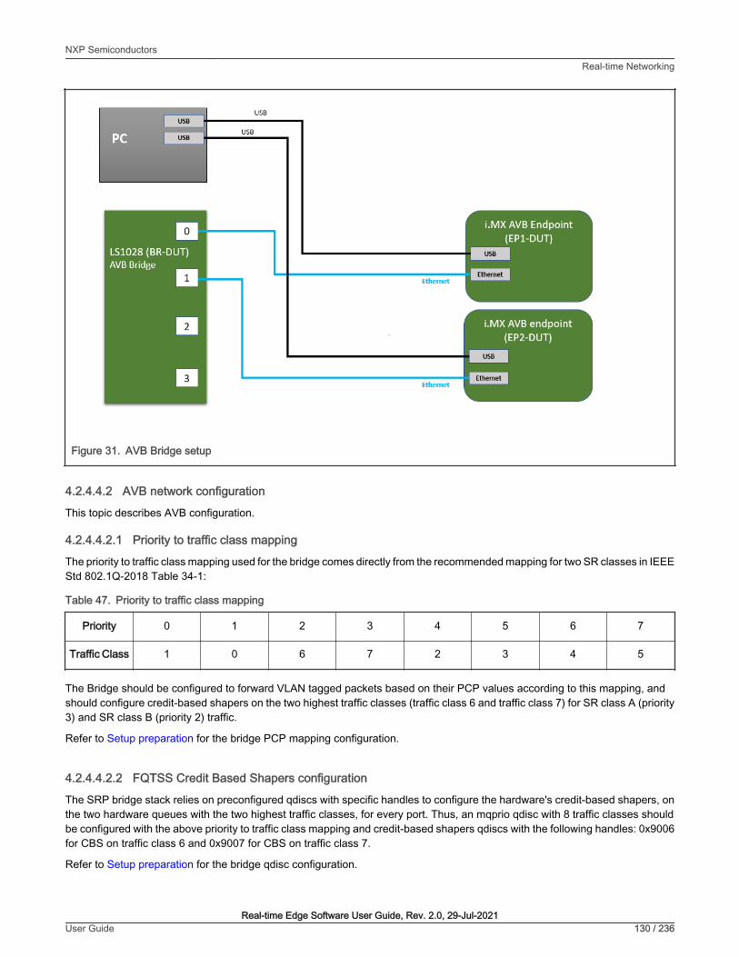
Figure 31. AVB Bridge setup
4.2.4.4.2 AVB network configuration
This topic describes AVB configuration.
4.2.4.4.2.1 Priority to traffic class mapping
The priority to traffic class mapping used for the bridge comes directly from the recommended mapping for two SR classes in IEEEStd 802.1Q-2018 Table 34-1:
Table 47. Priority to traffic class mapping
Priority 0 1 2 3 4 5 6 7
Traffic Class 1 0 6 7 2 3 4 5
The Bridge should be configured to forward VLAN tagged packets based on their PCP values according to this mapping, andshould configure credit-based shapers on the two highest traffic classes (traffic class 6 and traffic class 7) for SR class A (priority3) and SR class B (priority 2) traffic.
Refer to Setup preparation for the bridge PCP mapping configuration.
4.2.4.4.2.2 FQTSS Credit Based Shapers configuration
The SRP bridge stack relies on preconfigured qdiscs with specific handles to configure the hardware's credit-based shapers, onthe two hardware queues with the two highest traffic classes, for every port. Thus, an mqprio qdisc with 8 traffic classes shouldbe configured with the above priority to traffic class mapping and credit-based shapers qdiscs with the following handles: 0x9006for CBS on traffic class 6 and 0x9007 for CBS on traffic class 7.
Refer to Setup preparation for the bridge qdisc configuration.
NXP SemiconductorsReal-time Networking
Real-time Edge Software User Guide, Rev. 2.0, 29-Jul-2021User Guide 130 / 236
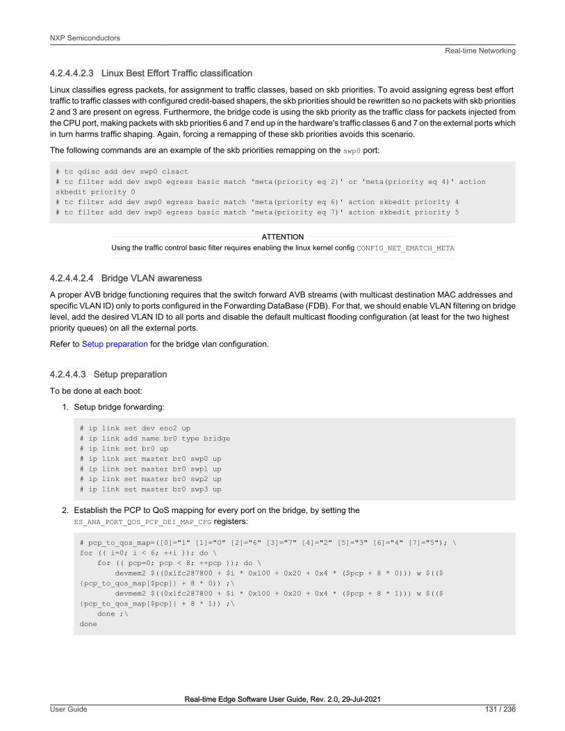
4.2.4.4.2.3 Linux Best Effort Traffic classification
Linux classifies egress packets, for assignment to traffic classes, based on skb priorities. To avoid assigning egress best efforttraffic to traffic classes with configured credit-based shapers, the skb priorities should be rewritten so no packets with skb priorities2 and 3 are present on egress. Furthermore, the bridge code is using the skb priority as the traffic class for packets injected fromthe CPU port, making packets with skb priorities 6 and 7 end up in the hardware's traffic classes 6 and 7 on the external ports whichin turn harms traffic shaping. Again, forcing a remapping of these skb priorities avoids this scenario.
The following commands are an example of the skb priorities remapping on the swp0 port:
# tc qdisc add dev swp0 clsact# tc filter add dev swp0 egress basic match 'meta(priority eq 2)' or 'meta(priority eq 4)' action skbedit priority 0# tc filter add dev swp0 egress basic match 'meta(priority eq 6)' action skbedit priority 4# tc filter add dev swp0 egress basic match 'meta(priority eq 7)' action skbedit priority 5
Using the traffic control basic filter requires enabling the linux kernel config CONFIG_NET_EMATCH_META
ATTENTION
4.2.4.4.2.4 Bridge VLAN awareness
A proper AVB bridge functioning requires that the switch forward AVB streams (with multicast destination MAC addresses andspecific VLAN ID) only to ports configured in the Forwarding DataBase (FDB). For that, we should enable VLAN filtering on bridgelevel, add the desired VLAN ID to all ports and disable the default multicast flooding configuration (at least for the two highestpriority queues) on all the external ports.
Refer to Setup preparation for the bridge vlan configuration.
4.2.4.4.3 Setup preparation
To be done at each boot:
1. Setup bridge forwarding:
# ip link set dev eno2 up# ip link add name br0 type bridge# ip link set br0 up# ip link set master br0 swp0 up# ip link set master br0 swp1 up# ip link set master br0 swp2 up# ip link set master br0 swp3 up
2. Establish the PCP to QoS mapping for every port on the bridge, by setting theES_ANA_PORT_QOS_PCP_DEI_MAP_CFG registers:
# pcp_to_qos_map=([0]="1" [1]="0" [2]="6" [3]="7" [4]="2" [5]="3" [6]="4" [7]="5"); \for (( i=0; i < 6; ++i )); do \ for (( pcp=0; pcp < 8; ++pcp )); do \ devmem2 $((0x1fc287800 + $i * 0x100 + 0x20 + 0x4 * ($pcp + 8 * 0))) w $((${pcp_to_qos_map[$pcp]} + 8 * 0)) ;\ devmem2 $((0x1fc287800 + $i * 0x100 + 0x20 + 0x4 * ($pcp + 8 * 1))) w $((${pcp_to_qos_map[$pcp]} + 8 * 1)) ;\ done ;\done
NXP SemiconductorsReal-time Networking
Real-time Edge Software User Guide, Rev. 2.0, 29-Jul-2021User Guide 131 / 236

3. Configure the qdiscs and shapers, with the correct handles, for every external port:
# pcp_to_qos_map=([0]="1" [1]="0" [2]="6" [3]="7" [4]="2" [5]="3" [6]="4" [7]="5"); \avb_ports="swp0 swp1 swp2 swp3"; \for port in $avb_ports; do \ tc qdisc add dev $port root handle 100: mqprio num_tc 8 map ${pcp_to_qos_map[@]} queues 1@0 1@1 1@2 1@3 1@4 1@5 1@6 1@7 hw 0 ; \ tc qdisc replace dev $port handle 0x9007 parent 100:8 \ cbs locredit -2147483646 hicredit 2147483647 sendslope -1000000 idleslope 0 offload 0 ; \ tc qdisc replace dev $port handle 0x9006 parent 100:7 \ cbs locredit -2147483646 hicredit 2147483647 sendslope -1000000 idleslope 0 offload 0 ; \done
The most important CBS parameters for every port device are the parent, which should match the traffic class 6and 7, and handle, which should be 0x9006 and 0x9007. The other parameters are just initialization values andwill be overridden by the stack at run time stream configuration: offload will be set to 1 to offload the operation tohardware, idleslope and sendslope will be set depending on stream and port bit rates and the credit values will bekept at their min and max values as they don't directly affect the hardware shaping operation)
ATTENTION
4. Enable Vlan filtering, set the correct Vlan IDs and disable multicast flooding, on the two highest queue piorities (by settingthe ES_ANA_ANA_FLOODING registers to PGID_CPU 58 ), for every external port:
# ip link set br0 type bridge vlan_filtering 1# bridge vlan add dev swp0 vid 2 master# bridge vlan add dev swp1 vid 2 master# bridge vlan add dev swp2 vid 2 master# bridge vlan add dev swp3 vid 2 master# devmem2 0x1fc288a00 w 0x0003CF7A# devmem2 0x1fc288a04 w 0x0003CF7A
5. Start the AVB and gPTP stacks:
# avb.sh start
4.2.4.4.4 Evaluation instructions
1. Reset all endpoints and the bridge.
2. Using the procedures described above, configure the bridge and start the stack on all connected devices (bridgeand endpoints)
3. After a few seconds, AVB endpoints should be synchronized through gPTP
4. Connect an SR class A (or SR class B) stream from EP-DUT2 as talker to EP-DUT1 as listener: the stream should beforwarded correctly to the listener endpoint
4.2.4.4.4.1 gPTP Operation
If the gPTP protocol is running correctly on all devices, the following line should appear in the bridge gptp log file for every portconnected to a gPTP capable device:
gptp_stats_dump: Port(0) domain(0, 0): Role: Master Link: Up asCapable: Yes neighborGptpCapable: Yes...
NXP SemiconductorsReal-time Networking
Real-time Edge Software User Guide, Rev. 2.0, 29-Jul-2021User Guide 132 / 236

gptp_stats_dump: Port(1) domain(0, 0): Role: Master Link: Up asCapable: Yes neighborGptpCapable: Yes
Refer to , for more details on gPTP Bridge operation.
AVB endpoints can be configured to run at a fixed link speed of 100 Mbits/s and cause to have a pDelay > 800ns making the port not asCapable. In that case, forcing the link speed at 1Gbits/s will make the pDelay under thethreshold and have a proper gPTP operation
ATTENTION
4.2.4.4.4.2 SRP Operation
A detailed view on the SRP protocol communications (Domain declaration, SRP port boundary, Talker/Listener declarations andregistration ...) can be followed by printing the SRP specific logs from the AVB bridge stack logfile /var/log/avb-br :
# tail -f /var/log/avb-br | grep srp
On stream connection, the FQTSS and FDB operation should be printed in the AVB bridge stack logfile:
• Stack log shows the FQTSS configuration for the port facing the AVB listener:
fqtss_set_oper_idle_slope : logical_port(2) port (swp0, ifindex 5) tc(7) cbs_qdisc_handle(9007:0): set idle_slope 7872000
• Stack log shows the FDB configuration for the port facing the AVB listener:
bridge_rtnetlink : add MDB: bridge (br0, ifindex 9) logical_port(2) port (swp0, ifindex 5) mac_addr(91:e0:f0:00:fe:11) vlan_id(2)
Also, the same configuration can be checked using the Linux standard tools (tc and bridge)
• TC tool shows the FQTSS configuration for the port facing the AVB listener:
# tc qdisc show dev swp0qdisc mqprio 100: root tc 8 map 1 0 6 7 2 3 4 5 0 0 0 0 0 0 0 0 queues:(0:0) (1:1) (2:2) (3:3) (4:4) (5:5) (6:6) (7:7)qdisc pfifo 0: parent 9006: limit 1000pqdisc pfifo 0: parent 9007: limit 1000pqdisc pfifo_fast 0: parent 100:6 bands 3 priomap 1 2 2 2 1 2 0 0 1 1 1 1 1 1 1 1qdisc pfifo_fast 0: parent 100:5 bands 3 priomap 1 2 2 2 1 2 0 0 1 1 1 1 1 1 1 1qdisc pfifo_fast 0: parent 100:4 bands 3 priomap 1 2 2 2 1 2 0 0 1 1 1 1 1 1 1 1qdisc pfifo_fast 0: parent 100:3 bands 3 priomap 1 2 2 2 1 2 0 0 1 1 1 1 1 1 1 1qdisc pfifo_fast 0: parent 100:2 bands 3 priomap 1 2 2 2 1 2 0 0 1 1 1 1 1 1 1 1qdisc pfifo_fast 0: parent 100:1 bands 3 priomap 1 2 2 2 1 2 0 0 1 1 1 1 1 1 1 1qdisc cbs 9006: parent 100:7 hicredit 2147483647 locredit -2147483646 sendslope -1000000 idleslope 0 offload 0qdisc cbs 9007: parent 100:8 hicredit 2147483647 locredit -2147483648 sendslope -992128 idleslope 7872 offload 1
• Bridge tool shows the FDB configuration for the port facing the AVB listener:
# bridge mdb showdev br0 port swp0 grp 91e0:f000:fe11:: permanent offload vid 2
NXP SemiconductorsReal-time Networking
Real-time Edge Software User Guide, Rev. 2.0, 29-Jul-2021User Guide 133 / 236

4.2.4.5 TSN endpoint sample application
4.2.4.5.1 Requirements
• Two TSN endpoints (i.MX 8M Plus EVK)
• One TSN bridge (LS1028ARDB)
The second IO Device is optional.
NOTE
Figure 32. TSN endpoint sample application setup
4.2.4.5.2 Configuring GenAVB/TSN stack and example applications
The change from one configuration to another is made by modifying the /etc/genavb/config file. This file specifies a pair ofconfiguration files:
1. APPS_CFG_FILE (apps-*.cfg) points to a file containing a demo configuration (application to use, options...). It is parsedby the startup script avb.sh
2. GENAVB_CFG_FILE (genavb-*.cfg) points to a file containing the configuration of the GenAVB/TSN stack and is parsedby the stack.
A configuration profile is made of a pair of cfg files. The file /etc/genavb/config already groups the cfg files by pairs. Set thePROFILE variable to choose the desired configuration profile.
4.2.4.5.3 TSN network configuration
This topic describes TSN configuration.
NXP SemiconductorsReal-time Networking
Real-time Edge Software User Guide, Rev. 2.0, 29-Jul-2021User Guide 134 / 236

4.2.4.5.3.1 Streams
The stream details can be used for analysis and also for computing scheduled traffic timings.
Table 48. TSN streams definition
Stream No Source Destination Unicast/Multicast
DestinationMAC Address Vlan ID Vlan PCP
FrameLength1
(bytes)
Stream1 Controller IO device(s) Multicast 91:e0:f0:00:fe:70 2 5 84
Stream2 IO device 1 Controller Multicast 91:e0:f0:00:fe:71 2 5 84
Stream3 IO device 2 Controller Multicast 91:e0:f0:00:fe:80 2 5 84
1. The frame length includes inter frame gap, preamble, start of frame and CRC (can be used as is for timing calculations)
4.2.4.5.3.2 Scheduled traffic
For deterministic packet transmission the use of scheduled traffic is required both on endpoints and bridges.
The default scheduling configuration for the TSN endpoint example application, as shown in Figure 29, leads to the followingtraffic schedules.
4.2.4.5.3.2.1 EndpointsEndpoints are running a schedule with a 2000us period. The base offset of the schedule is aligned to gPTP time modulo 1 second.
Controller transmit gate (for Stream1) opens at 500us offset (relative to the period start).
IO device transmit gate (for Stream2/3) opens at 1000us + 500us offset (relative to the period start).
The gate open interval is around 4us (enough to accommodate the stream frame length plus some margin).
The 500us offset is related to the worst case application latency to send its frame to its peer(s). This value provides a good marginfor a Linux PREEMPT-RT system but can be lowered on a well-tuned system.
4.2.4.5.3.2.2 BridgesThe schedule for all Bridges and all Bridge ports that transmit one of the streams above, must have a 2000 μs period and a baseoffset aligned to gPTP time modulo 1 second.
One possible schedule is to open transmit gate (for the ports and queues transmitting Stream 1) at offset 500 μs and use a gateopen interval that accommodates the worst propagation delay.
It is also possible to use a fixed gate open interval but increase the transmit time offset at each hop along the stream path.
For ports and queues transmitting Stream 2 and 3, open the transmit gate at offset 1000 + 500 μs.
4.2.4.5.4 Setup preparation
One of the TSN endpoint needs to be configured as “controller” and the other one as “IO device”. Both endpoints are connectedto the TSN bridge.
4.2.4.5.4.1 Preparing the controller
To be done once:
NXP SemiconductorsReal-time Networking
Real-time Edge Software User Guide, Rev. 2.0, 29-Jul-2021User Guide 135 / 236

1. Edit the GenAVB configuration file using the following command at the Linux prompt:
# vi /etc/genavb/config
2. Set the configuration profile to PROFILE 1:
PROFILE=1
3. Exit and save.
To be done at each boot:
1. Enable reception of packets on VLAN 2 (VLAN hardware filtering is enabled by default on recent kernels):
# ip link add link eth1 type vlan id 2
2. Enable threaded NAPI and fine-tune the CPU core affinities of the NAPI kthreads:
# echo 1 > /sys/class/net/eth1/threaded# taskset -p 4 `pgrep irq/61-eth1`# chrt -pf 66 `pgrep irq/61-eth1`# taskset -p 4 `pgrep napi/eth1-rx-0`# chrt -pf 65 `pgrep napi/eth1-rx-0`# taskset -p 4 `pgrep napi/eth1-tx-1`# chrt -pf 1 `pgrep napi/eth1-tx-1`# taskset -p 2 `pgrep napi/eth1-tx-2`# chrt -pf 1 `pgrep napi/eth1-tx-2`# taskset -p 8 `pgrep napi/eth1-rx-1`# taskset -p 8 `pgrep napi/eth1-rx-2`# taskset -p 8 `pgrep napi/eth1-rx-3`# taskset -p 8 `pgrep napi/eth1-rx-4`# taskset -p 8 `pgrep napi/eth1-tx-0`
3. Start the tsn-app application:
# avb.sh start
4. Setup scheduled traffic using tc (may be done before or after starting tsn-app):
# tc qdisc add dev eth1 parent root handle 100 taprio \num_tc 3 \map 0 0 0 0 0 1 2 0 0 0 0 0 0 0 0 0 \queues 1@0 1@1 1@2 \base-time 000500000 \sched-entry S 0x2 4000 \sched-entry S 0x5 1996000 \flags 0x2
4.2.4.5.4.2 Preparing IO device(s)
To be done once:
1. Edit the GenAVB configuration file using the following command at the Linux prompt:
# vi /etc/genavb/config
2. Set the configuration profile to PROFILE 2:
PROFILE=2
NXP SemiconductorsReal-time Networking
Real-time Edge Software User Guide, Rev. 2.0, 29-Jul-2021User Guide 136 / 236

3. Exit and save.
To be done at each boot:
1. Enable reception of packets on VLAN 2 (VLAN hardware filtering is enabled by default on recent kernels):
# ip link add link eth1 type vlan id 2
2. Enable threaded NAPI and fine-tune the CPU core affinities of the NAPI kthreads:
# echo 1 > /sys/class/net/eth1/threaded# taskset -p 4 `pgrep irq/61-eth1`# chrt -pf 66 `pgrep irq/61-eth1`# taskset -p 4 `pgrep napi/eth1-rx-0`# chrt -pf 65 `pgrep napi/eth1-rx-0`# taskset -p 4 `pgrep napi/eth1-tx-1`# chrt -pf 1 `pgrep napi/eth1-tx-1`# taskset -p 2 `pgrep napi/eth1-tx-2`# chrt -pf 1 `pgrep napi/eth1-tx-2`# taskset -p 8 `pgrep napi/eth1-rx-1`# taskset -p 8 `pgrep napi/eth1-rx-2`# taskset -p 8 `pgrep napi/eth1-rx-3`# taskset -p 8 `pgrep napi/eth1-rx-4`# taskset -p 8 `pgrep napi/eth1-tx-0`
3. Start the tsn-app application:
# avb.sh start
4. Setup scheduled traffic using tc (may be done before or after starting tsn-app):
# tc qdisc add dev eth1 parent root handle 100 taprio \num_tc 3 \map 0 0 0 0 0 1 2 0 0 0 0 0 0 0 0 0 \queues 1@0 1@1 1@2 \base-time 001500000 \sched-entry S 0x2 4000 \sched-entry S 0x5 1996000 \flags 0x2
4.2.4.5.4.3 Preparing the Bridge
Refer to section TSN configuration and Tc-taprio usage to configure scheduled traffic on the LS1028ARDB board.
The schedule described in section Bridges should be followed.
The below steps should be done at each boot:
1. Setup bridge forwarding:
# ip link set dev eno2 up# ip link add name br0 type bridge# ip link set br0 up# ip link set master br0 swp0 up# ip link set master br0 swp1 up# ip link set master br0 swp2 up# ip link set master br0 swp3 up
NXP SemiconductorsReal-time Networking
Real-time Edge Software User Guide, Rev. 2.0, 29-Jul-2021User Guide 137 / 236

2. Start the gPTP stack:
# fgptp.sh start
3. Setup scheduled traffic (see above)
# tc qdisc del dev swp0 root# tc qdisc del dev swp1 root# tc qdisc del dev swp2 root
# tc qdisc replace dev swp0 root taprio \ num_tc 8 \ map 0 1 2 3 4 5 6 7 \ queues 1@0 1@1 1@2 1@3 1@4 1@5 1@6 1@7 \ base-time 1500000 \ sched-entry S 0x20 20000 \ sched-entry S 0xdf 1980000 \ flags 0x2
# tc qdisc replace dev swp1 root taprio \ num_tc 8 \ map 0 1 2 3 4 5 6 7 \ queues 1@0 1@1 1@2 1@3 1@4 1@5 1@6 1@7 \ base-time 500000 \ sched-entry S 0x20 20000 \ sched-entry S 0xdf 1980000 \ flags 0x2
# tc qdisc replace dev swp2 root taprio \ num_tc 8 \ map 0 1 2 3 4 5 6 7 \ queues 1@0 1@1 1@2 1@3 1@4 1@5 1@6 1@7 \ base-time 500000 \ sched-entry S 0x20 20000 \ sched-entry S 0xdf 1980000 \ flags 0x2
4.2.4.5.4.4 Preparing the OPC UA client
In order to visualize the data exposed by the TSN endpoint application OPC UA server it is required to use an OPC UA client ona PC connected to the bridge.
1. Install an OPC UA client on a PC:
a. FreeOpcUa: client with a Qt GUI interface.
Can be found here: http://freeopcua.github.io/
b. opcua-commander: CLI alternative based nodejs node-opcua stack. Can be found here:
https://github.com/node-opcua/opcua-commander
2. Connect the PC to the bridge. If not already done, setup IP addresses on the endpoint running the TSN exampleapplication and also on the PC. Then, make sure you can successfully ping the endpoint using the PC.
4.2.4.5.5 Evaluation instructions
1. Reset all endpoints.
2. Using the procedures described above, start the gPTP stack on the bridge, and the tsn-app application on theendpoints.
NXP SemiconductorsReal-time Networking
Real-time Edge Software User Guide, Rev. 2.0, 29-Jul-2021User Guide 138 / 236

3. Enable scheduled traffic on the endpoints (and the bridge) with the configuration(s) described above.
4. After a few seconds, TSN endpoints should be synchronized through gPTP and exchanging packets at the rate of 500packets per second (pps). In order to observe this behavior, logs should be checked.
4.2.4.5.5.1 gPTP operation
If the gPTP protocol is running correctly on an endpoint or on the bridge, the following line should appear in the gptp log file (referto gPTP Endpoint for more details):
gptp_stats_dump: Port(0) domain(0,0) : Role: Slave Link : Up AS_Capable: Yes
If the device is grand master, the role field should be “Master” otherwise it should be “Slave”. The line appears periodically, butthe role should not change over time, except for significant events (such as a cable disconnection).
4.2.4.5.5.2 Baseline tsn-app operation
If the TSN endpoint sample application is running correctly and receiving valid packets, the following points may be verified in thetsn_app log file (refer to TSN Endpoint example application for more details).
The following line should appear at regular intervals:
socket_stats_print : link up
The "valid frames" counter should increment by 2500 (500 pps for 5 seconds) between two appearances of the following log:
socket_stats_print : valid frames : XXXXX
The various error counters should not increment (it is normal to have non-zero values, because of the startup period when gPTPand/or the remote tsn-app endpoint may not be running and stable):
• "sched early", "sched late", "sched missed", "sched timeout", "sched discont", "clock err"
• "err id", "err ts", "err underflow"
• "frames err" (for both RX and TX directions)
The checks above apply to all tsn-app endpoints, whether they be the controller or one of the IO devices.
[other]
4.2.4.5.5.3 Scheduled traffic evaluation with no concurrent traffic
The observations below assume an otherwise idle system receiving and sending traffic only through the tsn-app application, witha 802.1Qbv schedule in place on all devices (tsn-app endpoints, bridge).
Scheduling error statistics ("sched err") should respect the following:
• min around 8µs
• avg around 11µs
• max around 25µs
stats(0xaaab06ed74b0) sched err min 8817 mean 11120 max 22077 rms^2 125202075 stddev^2 1544829 absmin 7417 absmax 1882057
Processing time statistics ("processing time") should respect the following:
• min around 23µs
• avg around 29µs
NXP SemiconductorsReal-time Networking
Real-time Edge Software User Guide, Rev. 2.0, 29-Jul-2021User Guide 139 / 236
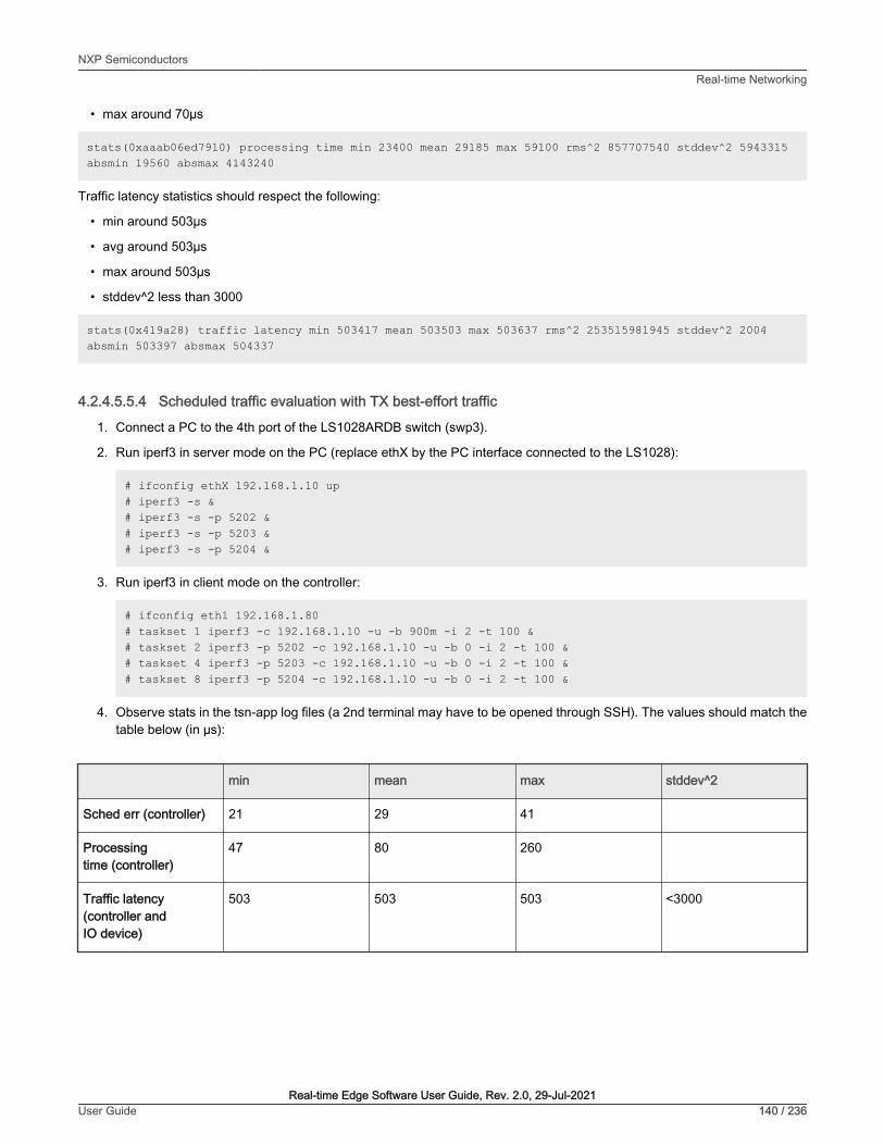
• max around 70µs
stats(0xaaab06ed7910) processing time min 23400 mean 29185 max 59100 rms^2 857707540 stddev^2 5943315 absmin 19560 absmax 4143240
Traffic latency statistics should respect the following:
• min around 503µs
• avg around 503µs
• max around 503µs
• stddev^2 less than 3000
stats(0x419a28) traffic latency min 503417 mean 503503 max 503637 rms^2 253515981945 stddev^2 2004 absmin 503397 absmax 504337
4.2.4.5.5.4 Scheduled traffic evaluation with TX best-effort traffic
1. Connect a PC to the 4th port of the LS1028ARDB switch (swp3).
2. Run iperf3 in server mode on the PC (replace ethX by the PC interface connected to the LS1028):
# ifconfig ethX 192.168.1.10 up # iperf3 -s &# iperf3 -s -p 5202 &# iperf3 -s -p 5203 &# iperf3 -s -p 5204 &
3. Run iperf3 in client mode on the controller:
# ifconfig eth1 192.168.1.80# taskset 1 iperf3 -c 192.168.1.10 -u -b 900m -i 2 -t 100 &# taskset 2 iperf3 -p 5202 -c 192.168.1.10 -u -b 0 -i 2 -t 100 &# taskset 4 iperf3 -p 5203 -c 192.168.1.10 -u -b 0 -i 2 -t 100 &# taskset 8 iperf3 -p 5204 -c 192.168.1.10 -u -b 0 -i 2 -t 100 &
4. Observe stats in the tsn-app log files (a 2nd terminal may have to be opened through SSH). The values should match thetable below (in µs):
min mean max stddev^2
Sched err (controller) 21 29 41
Processingtime (controller)
47 80 260
Traffic latency(controller andIO device)
503 503 503 <3000
NXP SemiconductorsReal-time Networking
Real-time Edge Software User Guide, Rev. 2.0, 29-Jul-2021User Guide 140 / 236

4.2.4.5.5.5 Scheduled traffic evaluation with RX best-effort traffic
By default, the tsn-app traffic is processed in the same queue as best-effort untagged traffic. To more easily validatetsn-app with best-effort traffic, we should add a VLAN tag with PCP=0 to best-effort packets so they are dispatchedinto a different queue on receive.
[other]
1. Connect a PC to the 4th port of the LS1028ARDB switch (swp3).
2. Run iperf3 in server mode on the controller:
# ip link add link eth1 name eth1.5 type vlan id 5# ifconfig eth1.5 192.168.5.80 up# iperf3 -s
3. Run iperf3 in client mode on the PC (replace ethX by the PC interface connected to the LS1028):
# ip link add link ethX name ethX.5 type vlan id 5# ifconfig ethX.5 192.168.5.10 up# iperf3 -c 192.168.5.80 -u -b 0 -l 64 -i2 -t 100
4. Observe stats in the tsn-app log file (a 2nd terminal may have to be opened through SSH). The values should match thetable below (in µs):
min mean max stddev^2
Sched err (controller) 9 13 26
Processingtime (controller)
25 33 70
Traffic latency(controller andIO device)
503 503 503 <130000
4.2.4.5.5.6 OPC UA server evaluation
The OPC UA server address is in this format : opc.tcp://<endpoint IP address>:4840/
Once connected, the server objects can be browsed and accessed. The same statistics described in the TSN example applicationlogs are available as OPC UA objects. The OPC UA server traffic is classified as best effort and doesn't affect the timesensitive traffic.
See below screenshot using FreeOPCUA GUI client:
NXP SemiconductorsReal-time Networking
Real-time Edge Software User Guide, Rev. 2.0, 29-Jul-2021User Guide 141 / 236

Figure 33. FreeOPCUA GUI client
4.2.5 Configuration files
4.2.5.1 System
The system configuration file, located in /etc/genavb/system.cfg, lists system network interface names and PTP hardwareclock device names. The default values are used if the configuration file or the option key are missing. The values in the installedfile may also required to be updated to match the system configuration.
This section lists network interface names.
Currently endpoint package supports a single endpoint and bridge package a single bridge (with up to 5 ports).
Table 49. Logical ports
Name Key Default value Description
Endpoint interface endpoint eth0
Endpoint network interfacename. Only valid for endpointpackage, otherwise should beset to “off”
Bridge 0 interfaces bridge_0
SJA1105P_p0,SJA1105P_p1,SJA1105P_p2,SJA1105P_p3,SJA1105P_p4*
Bridge 0 network interfacenames (comma separated).Only valid for bridge package,otherwise should be set to “off”
This section lists clock device names.
NXP SemiconductorsReal-time Networking
Real-time Edge Software User Guide, Rev. 2.0, 29-Jul-2021User Guide 142 / 236

Clocks names are either a PHC device name or a generic software clock (sw_clock). Local clock points to a PHC device, targetclocks point to either:
• The same PHC device as local clock (gPTP time is reflected in the local clock)
• A generic software clock (in which case gPTP time is not reflected in the local clock).
Table 50. Clock
Name Key Default value Description
Endpoint gPTP domain 0target clock endpoint_gptp_0 /dev/ptp0
Endpoint clock for gPTPdomain 0 target clock. Onlyvalid for endpoint package.
Endpoint gPTP domain 1target clock endpoint_gptp_1 sw_clock
Endpoint clock for gPTPdomain 1 target clock. Onlyvalid for endpoint package.
Endpoint local clock endpoint_local /dev/ptp0Endpoint clock for thelocal clock. Only valid forendpoint package.
Bridge gPTP domain 0target clock bridge_gptp_0 sw_clock
Bridge clock for gPTP domain0 target clock. Only valid forbridge package.
Bridge gPTP domain 1target clock bridge_gptp_1 sw_clock
Bridge clock for gPTP domain1 target clock. Only valid forbridge package.
Bridge local clock bridge_local /dev/ptp1 Bridge clock for the local clock.Only valid for bridge package.
4.2.5.2 gPTP
The gPTP general parameters as well as default domain (domain 0) parameters are defined in the following configuration filesdepending on the package used:
• Endpoint package: /etc/genavb/fgptp.cfg
• Bridge package: /etc/genavb/fgptp-br.cfg
To enable other domains, new configuration files must be created with the associated domain instance appended to theconfiguration file name e.g.:
• Endpoint package, domain 1: /etc/genavb/fgptp.cfg-1
• Bridge package, domain 1: /etc/genavb/fgptp-br.cfg-1
By default the GenAVB/TSN gPTP stack is packaged with the general parameters configuration file (fgptp.cfgor fgptp-br.cfg) and a reference configuration for domain 1 (fgptp.cfg-1 or fgptp-br.cfg-1)
ATTENTION
4.2.5.2.1 General
Profile
The gPTP stack can operate in two different modes known as 'standard' or 'automotive' profiles.
NXP SemiconductorsReal-time Networking
Real-time Edge Software User Guide, Rev. 2.0, 29-Jul-2021User Guide 143 / 236

When the 'standard' profile is selected, the gPTP stack operates following the specifications described in IEEE 802.1AS.When the 'automotive' profile is selected, the gPTP stack operates following the specifications described in the AVnuAutoCDSFunctionalSpec_1.4 which is a subset of the IEEE 802.1AS standard optimized for automotive applications. IEEE802.1AS-2020 features are not available in 'automotive' profile (e.g. Multiple domains).
The automotive environment is unique in that it is a closed system. Every network device is known prior to startup and devices donot enter or leave the network, except in the case of failures. Because of the closed nature of the automotive network, it is possibleto simplify and improve gPTP startup performance. Specifically, functions like election of a grand master and calculations of wiredelays are tasks that can be optimized for a closed system.
Reverse sync feature control
The Reverse Sync feature (Avnu specification) should be used for test/evaluation purpose only. Usually, to measure the accuracyof the clock synchronization, the traditional approach is to use a 1 Pulse Per Second (1PPS) physical output. While this is agood approach, there may be cases where using a 1PPS output is not feasible. More flexible and fully relying on softwareimplementation the Reverse Sync feature serves the same objective using the standard gPTP Sync/Follow-Up messages to relaythe timing information, from the Slave back to the GM.
Neighbor propagation delay threshold
The parameter neighborPropDelayThresh defines the propagation time threshold, above which a port is not consideredcapable of participating in the IEEE 802.1AS protocol (see IEEE 802.1AS-2020 - 11.2.2 Determination of asCapable andasCapableAcrossDomains). If a computed neighborPropDelay exceeds neighborPropDelayThresh, then asCapable is set toFALSE for the port. This setting does not apply to Automotive profile where a link is always considered to be capable or runningIEEE 802.1AS.
IEEE 802.1AS-2011 Compatibility
The parameter force_2011 defines if the gPTP Stack operates following the IEEE 802.1AS-2011 standard, i.e. disabling theIEEE 802.1AS-2020 specifics features such as Multiple Domain support. The use of this option may, in some cases, improvecompatibility with gPTP equipement not supporting IEEE 802.1AS-2020 standard.
General configuration parameters1
Table 51. General parameters
Name Key Default value Range Description
Profile profile “standard” "standard" or"automotive"
Set fgptp main profile."standard" - IEEE 802.1ASspecs, "automotive" - AVnuautomotive profile
Grandmaster ID gm_id "0x0001f2fffe0025fe" 64bits EUIformat
Set static grandmaster ID inhost order (used by automotiveprofile, ignored in case ofstandard profile)
Domains domain_number0: for default domain
-1: for domains differentfrom 0
-1 to 127Disable (-1) or assign agPTP domain number to adomain instance.
802.1AS-2011 mode force_2011 no "no" or "yes"
Set to "yes" to force802.1AS-2011 standard. "no"to enable 802.1AS-2020full support.
Table continues on the next page...
NXP SemiconductorsReal-time Networking
Real-time Edge Software User Guide, Rev. 2.0, 29-Jul-2021User Guide 144 / 236

Table 51. General parameters (continued)
Name Key Default value Range Description
Log output level log_level info crit, err, init,info, or dbg
Set this configuration to dbg toenable debug mode
Reverse syncfeature control reverse_sync 0 0 or 1 Set to 1 to enable reverse sync
transmit on slave side
Reverse syncfeature interval reverse_sync_interval 112 32 to 10000 Reverse sync transmit interval
in ms units
Neighborpropagation
delay thresholdneighborPropDelayThresh 800 32 to
10000000Neighbor propagation delaythreshold expressed in ns
Statisticsoutput interval statsInterval 10 0 to 255
Statistics output intervalexpressed in seconds. Use 0 todisable statistics
1. For domain instances other than 0, only domain_number is configurable in this section.
4.2.5.2.2 Grandmaster parameters
This section defines the native Grand Master capabilities of a time-aware system (see IEEE 802.1AS-2020 - 8.6.2 PTP Instanceattributes). Grand Master capabilities parameters are defined in the main configuration file for gPTP domain 0 (e.g. fgptp.cfg) andin the additional per domain configuration files for other domains (e.g. fgptp.cfg-1).
gmCapable defines if the time-aware system is capable of being a grandmaster. By default gmCapable is set to 1 as in standardprofile operation the Grand Master is elected dynamically by the BMCA. In case of automotive profile gmCapable must be set oneach AED node to match the required network topology (i.e. within a given gPTP domain only one node must have its gmCapableproperty set to 1).
priority1, priority2, clockClass, clockAccuracy and offsetScaledLogVariance are parameters used by the Best Master Clockalgorithm to determine which of the Grand Master capable node within the gPTP domain has the highest priority/quality. Note thatthe lowest value for these parameters matches the highest priority/quality.
Grandmaster capabilities parameters1
Table 52. Grandmaster parameters
Name Key Default value Range Description
Grandmastercapable setting gmCapable 1 0 or 1
Set to 1 if the devicehas grandmaster capability.Ignored in automotive profileif the port is SLAVE.
Grandmasterpriority1 value priority1 248 for AED-E and
246 for AED-B 0 to 255 Set the priority1 value ofthis clock
Grandmasterpriority2 value priority2 248 0 to 255 Set the priority2 value of
this clock
Table continues on the next page...
NXP SemiconductorsReal-time Networking
Real-time Edge Software User Guide, Rev. 2.0, 29-Jul-2021User Guide 145 / 236

Table 52. Grandmaster parameters (continued)
Name Key Default value Range Description
Grandmaster clockclass value clockClass 248 0 to 255 Set the class value of
this clock
Grandmaster clockaccuracy value clockAccuracy 0xfe 0x0 to 0xff Set the accuracy value of
this clock
Grandmastervariance value offsetScaledLogVariance 17258 0x0 to 0xffff Set the offset scaled log
variance value of this clock
1. The parameters in this section are configurable for all supported domains.
4.2.5.2.3 Automotive parameters
The static pdelay feature is used only if the gPTP stack operates in automotive profile configuration.
At init time the gPTP stack's configuration file is parsed and based on neighborPropDelay_mode the specifiedinitial_neighborPropDelay is applied to all ports and used for synchronization until a pdelay response from the peer is received.This is done only if no previously stored pdelay is available from the nvram database specified by nvram_file. As soon as a pdelayresponse from the peer is received the 'real' pdelay value is computed, and used for current synchronization. An indication maythen be sent via callback up to the OS-dependent layer. Upon new indication the Host may update its nvram database and thestored value will be used at next restart for the corresponding port instead of the initial_neighborPropDelay. The granularity atwhich pdelay change indications are sent to the Host is defined by the neighborPropDelay_sensitivity parameter.
In the gPTP configuration file the neighborPropDelay_mode parameter is set to 'static' by default, meaning that a predefinedpropagation delay is used as described above while pdelay requests are still sent to the network.
The 'silent' mode behaves the same way as the 'static' mode except that pdelay requests are never sent at all to the network.
Optionally the neighborPropDelay_mode parameter can be set to standard forcing the stack to operate propagation delaymeasurements as specified in the 802.1AS specifications even if the automotive profile is selected.
(see AutoCDSFunctionalSpec-1_4 - 6.2.2 Persistent gPTP Values)
Table 53. Automotive parameters
Name Key Default value Value & Range Description
Pdelay mode neighborPropDelay_mode static 'static', 'silent'or 'standard'
Defines pdelaymechanism used
Static pdelayvalue initial_neighborPropDelay 250 0 to 10000 Predefined pdelay value applied
to all ports. Expressed in ns.
Static pdelaysensitivity neighborPropDelay_sensitivity 10 0 to 1000
Amount of ns between twopdelay measurements requiredto trigger a change indication.Expressed in ns.
Nvram filename nvram_file /etc/genavb/
fgptp.nvram Path and nvram file name.
NXP SemiconductorsReal-time Networking
Real-time Edge Software User Guide, Rev. 2.0, 29-Jul-2021User Guide 146 / 236
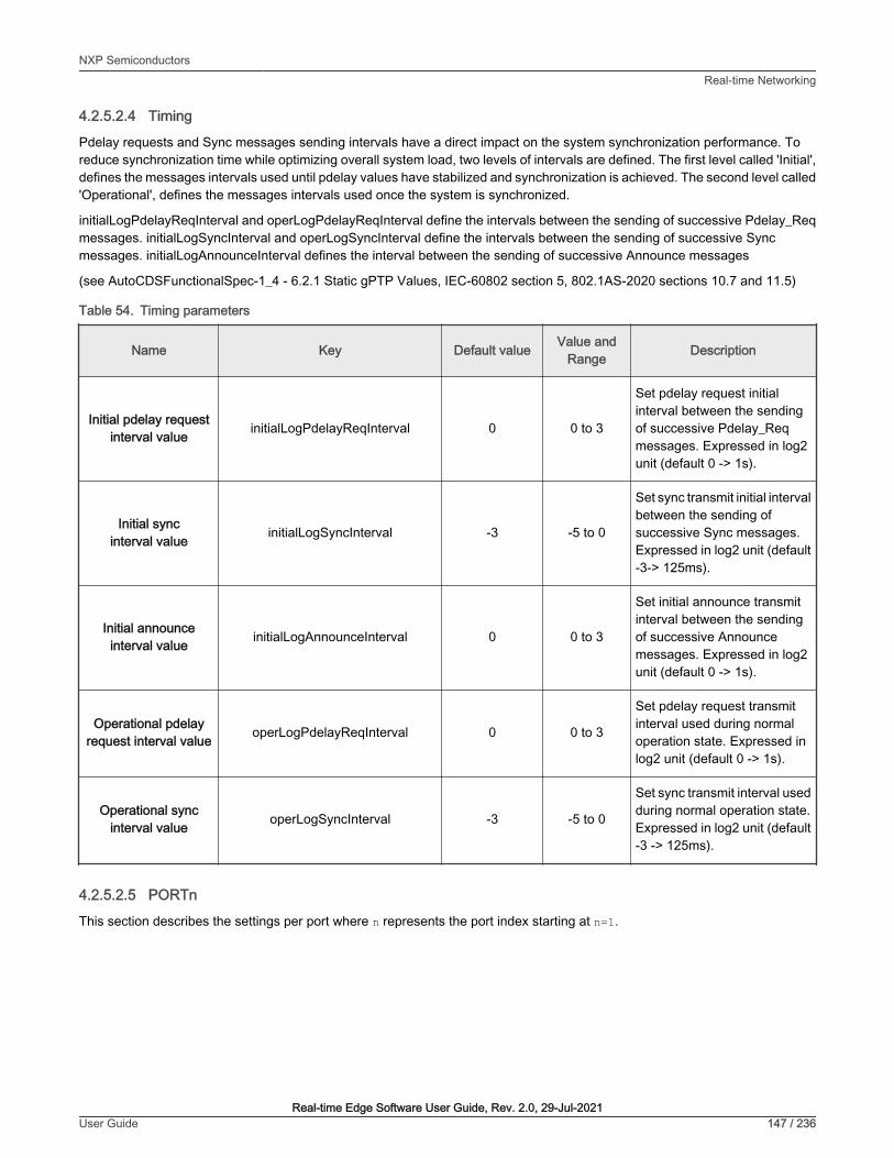
4.2.5.2.4 Timing
Pdelay requests and Sync messages sending intervals have a direct impact on the system synchronization performance. Toreduce synchronization time while optimizing overall system load, two levels of intervals are defined. The first level called 'Initial',defines the messages intervals used until pdelay values have stabilized and synchronization is achieved. The second level called'Operational', defines the messages intervals used once the system is synchronized.
initialLogPdelayReqInterval and operLogPdelayReqInterval define the intervals between the sending of successive Pdelay_Reqmessages. initialLogSyncInterval and operLogSyncInterval define the intervals between the sending of successive Syncmessages. initialLogAnnounceInterval defines the interval between the sending of successive Announce messages
(see AutoCDSFunctionalSpec-1_4 - 6.2.1 Static gPTP Values, IEC-60802 section 5, 802.1AS-2020 sections 10.7 and 11.5)
Table 54. Timing parameters
Name Key Default value Value andRange Description
Initial pdelay requestinterval value initialLogPdelayReqInterval 0 0 to 3
Set pdelay request initialinterval between the sendingof successive Pdelay_Reqmessages. Expressed in log2unit (default 0 -> 1s).
Initial syncinterval value initialLogSyncInterval -3 -5 to 0
Set sync transmit initial intervalbetween the sending ofsuccessive Sync messages.Expressed in log2 unit (default-3-> 125ms).
Initial announceinterval value initialLogAnnounceInterval 0 0 to 3
Set initial announce transmitinterval between the sendingof successive Announcemessages. Expressed in log2unit (default 0 -> 1s).
Operational pdelayrequest interval value operLogPdelayReqInterval 0 0 to 3
Set pdelay request transmitinterval used during normaloperation state. Expressed inlog2 unit (default 0 -> 1s).
Operational syncinterval value operLogSyncInterval -3 -5 to 0
Set sync transmit interval usedduring normal operation state.Expressed in log2 unit (default-3 -> 125ms).
4.2.5.2.5 PORTn
This section describes the settings per port where n represents the port index starting at n=1.
NXP SemiconductorsReal-time Networking
Real-time Edge Software User Guide, Rev. 2.0, 29-Jul-2021User Guide 147 / 236

Table 55. Port related parameters
Name Key Default value Value & Range Description
Port role portRole disabled 'slave', 'master', 'disabled'Static port role (ref. 802.1AS-2011,section 14.6.3, Table 10-1), applies to"automotive" profile only.
Ptp portenabled ptpPortEnabled 1 0 or 1
Set to 1 if both time-synchronizationand best master selection functionsof the port should be used(ref. 802.1AS-2011, sections 14.6.4and 10.2.4.12).
4.2.5.3 SRP
The SRP parameters are defined in the following configuration files, depending on the package used:
• Endpoint: /etc/genavb/srp.cfg
• Bridge: /etc/genavb/srp-br.cfg
The default values are used if the configuration file or the option key are missing. The values in the installed file may also requiredan update to match the system configuration.
This section lists general SRP stack component parameters.
Table 56. SRP General
Name Key Default value Range Description
Log output level log_level info crit, err, init, info, or dbg Log level for the SRPstack component.
This section lists MSRP parameters.
Table 57. MSRP
Name Key Default value Range Description
Enabled enabled 1 0-disabled, 1-enabled Enable/disable MSRPat run time.
4.2.6 Log filesSeveral log files are available at run time to monitor the different stack components.
4.2.6.1 gPTP Endpoint
Logs are stored in /var/log/fgptp.
• Linux command:
# tail –f /var/log/fgptp
• If the stack is configured in automotive mode, then the log contains:
Running fgptp in automotive profile on interface eth0
NXP SemiconductorsReal-time Networking
Real-time Edge Software User Guide, Rev. 2.0, 29-Jul-2021User Guide 148 / 236

• Port Role, Port AS-capability and link Status are reported each time there is a change in the link state (link is 802.1AScapable or not) or upon Grand Master (GM) change. This information is also displayed regularly along with currentsynchronization and pdelay statistics for each of the enabled gPTP domain:
Port(0) domain(0,0): role changed from DISABLED to SLAVE…Port(0) domain(0,0): Slave – Link: Up – AS_Capable: Yes
• Selected Grand Master (GM) capabilities are reported upon new GM selection. Root Identity represents the clock ID of thecurrently selected GM. Priority1, Priority2, Class and Accuracy describe the clock quality of the selected GM. Finally, theSource Port Identity of the peer master port (e.g. the bridge port the local slave port is connected to). This information isdisplayed for each of the enabled gPTP domain:
domain(0,0) Grand master: root identity 00049ffffe039e35domain(0,0) Grand master: priority1 245 priority2domain(0,0) Grand master: class 248 accuracy 248domain(0,0) Grand master: variance 17258domain(0,0) Grand master: source port identity 0001f2fffe0025fe, port number 2
• Synchronization State is reported upon GM selection (SYNCHRONIZED) or when no GM is detected (NOTSYNCHRONIZED). Synchronization Time expressed in ms represents the time it took for the local clock to reachsynchronization threshold starting from the first SYNC message received. This information is displayed for each of theenabled domain.
Port(0) domain(0) SYNCHRONIZED – synchronization time (ms): 250
• Pdelay (propagation delay) and local clock adjustments are printed out every 5 seconds. PDelay is expressed in ns unitsand represents the one-way delay from the endpoint and its peer master. Correction is expressed in parts per billionand represents the frequency adjustment performed to the local clock. Offset is expressed in ns represents the resultingdifference between the locally adjusted clock and the reference gPTP GrandMaster’s clock. (Min/Max/Avg and Varianceare computed for both Correction and Offset statistics). PDelay is displayed only for Domain 0. Correction and Offset aredisplayed for each of the enabled domain.
Port 0 domain(0,0): Propagation delay (ns): 37.60 min 34 avg 36 max 45 variance 17Port 0 domain(0,0): Correction applied to local clock (ppb): min -5603 avg 5572 max 5538 variance 148 Port 0 domain(0,0): Offset between GM and local clock (ns) min -12 avg 4 max 22 variance 111...Port 0 domain(1,20): Correction applied to local clock (ppb): min 32074 avg 32314 max 32574 variance 17695 Port 0 domain(1,20): Offset between GM and local clock (ns) min -61 avg 3 max 70 variance 1149
• The following per port per domain statistics (32 bits counters) are printed out every 15 seconds on slave and masterentities:
Table 58. Port statistics displayed on slave and master entities
Receive counters
PortStatRxPkts Number of gPTP packets received (ether type 0x88F7)
PortStatRxSyncCount Number of SYNC packets received
PortStatRxSyncReceiptTimeouts Number of SYNC packets receive timeout
PortStatRxFollowUpCount Number of FOLLOW-UP packets received
Table continues on the next page...
NXP SemiconductorsReal-time Networking
Real-time Edge Software User Guide, Rev. 2.0, 29-Jul-2021User Guide 149 / 236
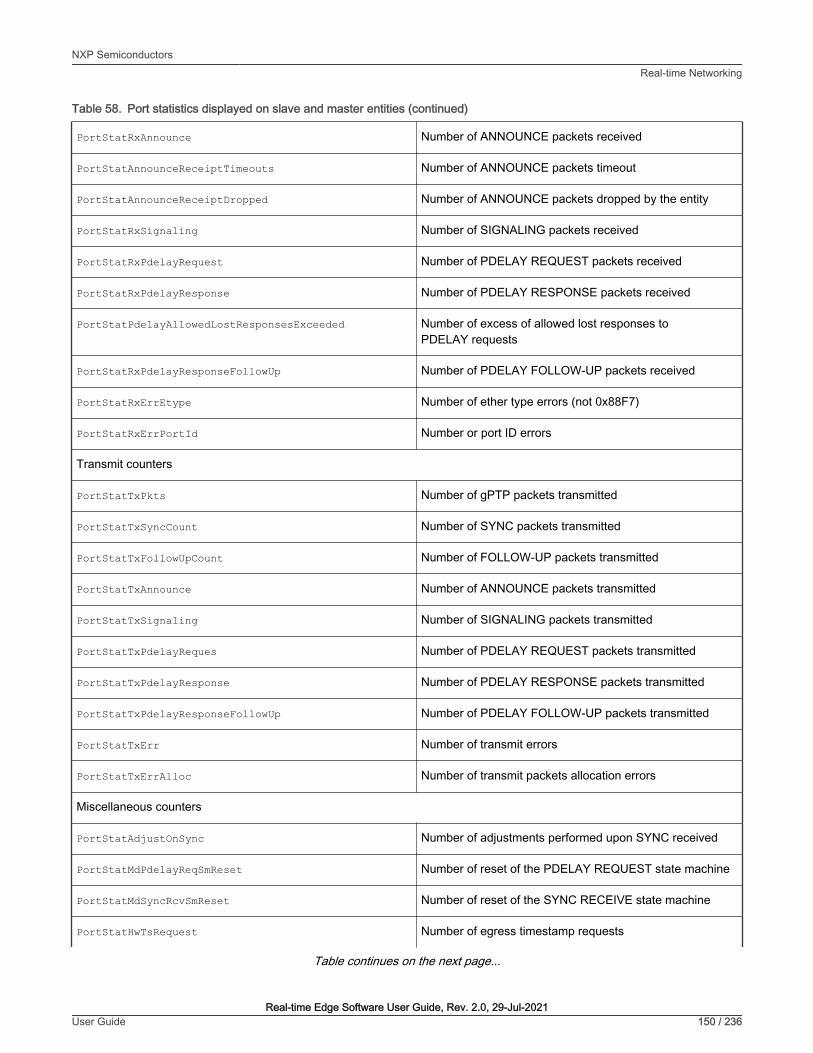
Table 58. Port statistics displayed on slave and master entities (continued)
PortStatRxAnnounce Number of ANNOUNCE packets received
PortStatAnnounceReceiptTimeouts Number of ANNOUNCE packets timeout
PortStatAnnounceReceiptDropped Number of ANNOUNCE packets dropped by the entity
PortStatRxSignaling Number of SIGNALING packets received
PortStatRxPdelayRequest Number of PDELAY REQUEST packets received
PortStatRxPdelayResponse Number of PDELAY RESPONSE packets received
PortStatPdelayAllowedLostResponsesExceeded Number of excess of allowed lost responses toPDELAY requests
PortStatRxPdelayResponseFollowUp Number of PDELAY FOLLOW-UP packets received
PortStatRxErrEtype Number of ether type errors (not 0x88F7)
PortStatRxErrPortId Number or port ID errors
Transmit counters
PortStatTxPkts Number of gPTP packets transmitted
PortStatTxSyncCount Number of SYNC packets transmitted
PortStatTxFollowUpCount Number of FOLLOW-UP packets transmitted
PortStatTxAnnounce Number of ANNOUNCE packets transmitted
PortStatTxSignaling Number of SIGNALING packets transmitted
PortStatTxPdelayReques Number of PDELAY REQUEST packets transmitted
PortStatTxPdelayResponse Number of PDELAY RESPONSE packets transmitted
PortStatTxPdelayResponseFollowUp Number of PDELAY FOLLOW-UP packets transmitted
PortStatTxErr Number of transmit errors
PortStatTxErrAlloc Number of transmit packets allocation errors
Miscellaneous counters
PortStatAdjustOnSync Number of adjustments performed upon SYNC received
PortStatMdPdelayReqSmReset Number of reset of the PDELAY REQUEST state machine
PortStatMdSyncRcvSmReset Number of reset of the SYNC RECEIVE state machine
PortStatHwTsRequest Number of egress timestamp requests
Table continues on the next page...
NXP SemiconductorsReal-time Networking
Real-time Edge Software User Guide, Rev. 2.0, 29-Jul-2021User Guide 150 / 236

Table 58. Port statistics displayed on slave and master entities (continued)
PortStatHwTsHandler Number of egress timestamp notification
PortStatNumSynchronizationLoss Number or synchronization loss on the slave endpoint (e.g.GM change, GM reference clock discontinuity...)
PortStatNumNotAsCapable Number of transitions from AS_Capable=TRUEto AS_Capable=FALSE
4.2.6.2 gPTP Bridge
Logs are stored in /var/log/fgptp-br.
• Linux command:
# tail –f /var/log/fgptp-br
• The bridge stack statistics are similar to the endpoint stack ones except that they are reported for each of the externalports of the switch (Port 0 to 3) and also for the internal port connected to the endpoint stack (Port 4) in case of Hybridsetup.
• Pdelay (propagation delay) is printed only for Domain 0. Link status, AS capability and Port Role are printed out for eachport and each gPTP domain.
Port 0 domain(0,0): Role: Disabled Link: Up AS_Capable: NoPort 1 domain(0,0): Role: Disabled Link: Up AS_Capable: NoPort 2 domain(0,0): Role: Disabled Link: Up AS_Capable: YesPort 2 domain(0,0): Propagation delay (ns): 433.98 min 425 avg 438 max 457 variance 87Port 3 domain(0,0): Role: Disabled Link: Up AS_Capable: NoPort 4 domain(0,0): Role Master Link: Up AS_Capable: YesPort 4 domain(0,0): Propagation delay (ns): 433.98 min 425 avg 438 max 457 variance 87...Port 0 domain(1,20): Role: Disabled Link: Up AS_Capable: NoPort 1 domain(1,20): Role: Disabled Link: Up AS_Capable: NoPort 2 domain(1,20): Role: Disabled Link: Up AS_Capable: YesPort 3 domain(1,20): Role: Disabled Link: Up AS_Capable: NoPort 4 domain(1,20): Role Master Link: Up AS_Capable: Yes
4.2.6.3 SRP Bridge
Logs are stored in /var/log/avb-br.
• Linux command:
# tail –f /var/log/avb-br | grep srp
• SRP protocol information is reported per port
INFO srp msrp_vector_add_event : port(0) domain(5, 2, 2) MSRP_ATTR_TYPE_DOMAIN MRP_ATTR_EVT_JOINMTINFO srp msrp_vector_add_event : port(0) domain(6, 3, 2) MSRP_ATTR_TYPE_DOMAIN MRP_ATTR_EVT_JOINMTINFO srp msrp_vector_add_event : port(1) domain(5, 2, 2) MSRP_ATTR_TYPE_DOMAIN MRP_ATTR_EVT_JOINMTINFO srp msrp_vector_add_event : port(1) domain(6, 3, 2) MSRP_ATTR_TYPE_DOMAIN MRP_ATTR_EVT_JOINMTINFO srp msrp_vector_add_event : port(2) domain(5, 2, 2) MSRP_ATTR_TYPE_DOMAIN
NXP SemiconductorsReal-time Networking
Real-time Edge Software User Guide, Rev. 2.0, 29-Jul-2021User Guide 151 / 236

MRP_ATTR_EVT_JOINMTINFO srp msrp_vector_add_event : port(2) domain(6, 3, 2) MSRP_ATTR_TYPE_DOMAIN MRP_ATTR_EVT_JOINMTINFO srp msrp_vector_add_event : port(4) domain(5, 2, 2) MSRP_ATTR_TYPE_DOMAIN MRP_ATTR_EVT_JOINMTINFO srp msrp_vector_add_event : port(4) domain(6, 3, 2) MSRP_ATTR_TYPE_DOMAIN MRP_ATTR_EVT_JOINMTINFO srp msrp_vector_handler : port(3) domain(5, 2, 2) MRP_ATTR_EVT_MTINFO srp msrp_vector_handler : port(3) domain(6, 3, 2) MRP_ATTR_EVT_MTINFO srp msrp_vector_handler : port(3) domain(5, 2, 2) MRP_ATTR_EVT_JOINMTINFO srp msrp_vector_handler : port(3) domain(6, 3, 2) MRP_ATTR_EVT_JOINMTINFO srp msrp_vector_add_event : port(3) domain(5, 2, 2) MSRP_ATTR_TYPE_DOMAIN MRP_ATTR_EVT_JOINININFO srp msrp_vector_add_event : port(3) domain(6, 3, 2) MSRP_ATTR_TYPE_DOMAIN MRP_ATTR_EVT_JOINININFO srp msrp_vector_add_event : port(3) domain(5, 2, 2) MSRP_ATTR_TYPE_DOMAIN MRP_ATTR_EVT_JOINININFO srp msrp_vector_add_event : port(3) domain(6, 3, 2) MSRP_ATTR_TYPE_DOMAIN MRP_ATTR_EVT_JOINININFO srp msrp_vector_add_event : port(0) domain(5, 2, 2) MSRP_ATTR_TYPE_DOMAIN MRP_ATTR_EVT_MTINFO srp msrp_vector_add_event : port(0) domain(6, 3, 2) MSRP_ATTR_TYPE_DOMAIN MRP_ATTR_EVT_MTINFO srp msrp_vector_add_event : port(1) domain(5, 2, 2) MSRP_ATTR_TYPE_DOMAIN MRP_ATTR_EVT_MTINFO srp msrp_vector_add_event : port(1) domain(6, 3, 2) MSRP_ATTR_TYPE_DOMAIN MRP_ATTR_EVT_MTINFO srp msrp_vector_add_event : port(2) domain(5, 2, 2) MSRP_ATTR_TYPE_DOMAIN MRP_ATTR_EVT_MTINFO srp msrp_vector_add_event : port(2) domain(6, 3, 2) MSRP_ATTR_TYPE_DOMAIN MRP_ATTR_EVT_MTINFO srp msrp_vector_add_event : port(4) domain(5, 2, 2) MSRP_ATTR_TYPE_DOMAIN MRP_ATTR_EVT_MTINFO srp msrp_vector_add_event : port(4) domain(6, 3, 2) MSRP_ATTR_TYPE_DOMAIN MRP_ATTR_EVT_MT
4.2.6.4 TSN Endpoint example application
Logs are stored in /var/log/tsn_app.
The TSN application has various counters and statistics which help to validate:
• application scheduling and processing timing statistics
• network traffic correctness and latency statistics
Most of the information in the logs are either:
• Counters: single integer values counting specific events (frames received, transmitted, errors, etc)
• Statistics: composite data over a series of measurements: min (minimum during the last period), mean (average ofmeasurements during the last period), max (maximum during the last period), rms^~(root mean square of measurementsduring the last period), stddev^2 (square of standard deviation during the last period), absmin(absolute minimum since theapplication start), absmax (absolute maximum since the application start)
• Histograms: number and size of slots of the histogram one the 1st line, array of counters for each slot on the 2nd line.
4.2.6.4.1 Main TSN task
The main TSN task logs are described below:
NXP SemiconductorsReal-time Networking
Real-time Edge Software User Guide, Rev. 2.0, 29-Jul-2021User Guide 152 / 236

• Scheduling counters (“sched” should increment of 500 per second):
INFO 1604531064 tsn_task_stats_print tsn task(0x37d8d630)INFO 1604531064 tsn_task_stats_print sched : 1700000INFO 1604531064 tsn_task_stats_print sched early : 0INFO 1604531064 tsn_task_stats_print sched late : 0INFO 1604531064 tsn_task_stats_print sched missed : 0INFO 1604531064 tsn_task_stats_print sched timeout : 0INFO 1604531064 tsn_task_stats_print clock discont : 0INFO 1604531064 tsn_task_stats_print clock err : 0
• Scheduling error statistics (difference between actual task scheduling time and programmed time, in ns):
stats(0x2ddd4560) sched err min 8062 mean 10662 max 18862 rms^2 116252492 stddev^2 2558383 absmin 2842 absmax 35082
• Scheduling error histogram (XXX ns bucket)
n_slot 101 slot_size 1000018081119 21722197 1676 7 0 0 0 0 0 0 0 0 0 0 0 0 0 0 0 0 0 0 0 0 0 0 0 0 0 0 0 0 0 0 0 0 0 0 0 0 0 0 0 0 0 0 0 0 0 0 0 0 0 0 0 0 0 0 0 0 0 0 0 0 0 0 0 0 0 0 0 0 0 0 0 0 0 0 0 0 0 0 0 0 0 0 0 0 0 0 0 0 0 0 0 0 0 0 0 0 0 0
• Processing time statistics (main task duration in ns)
stats(0x2ddd49c0) processing time min 21600 mean 27564 max 47460 rms^2 768483628 stddev^2 8664988 absmin 12540 absmax 152100
• Processing time histogram (XXX ns bucket)
n_slot 101 slot_size 10000 0 0 0 0 0 0 0 0 0 0 0 9 13 7 259 302 187 14273 64041 91896 427011 1473790 2154889 4239252 4681777 5682883 5516429 4915621 3789351 2688466 1709802 1036649 587716 327653 170711 89620 47637 25422 15211 9573 6908 4852 3694 3101 2910 3028 3036 3331 3091 2842 2375 1748 1251 895 585 342 208 100 63 64 26 21 13 9 14 6 7 4 4 6 3 4 1 0 2 2 1 1 0 0 0 1 0 0 0 0 0 0 0 0 0 0 0 0 0 0 0 0 0 1 0
• Total time statistics (scheduling error + processing time, in ins)
stats(0x2ddd4e20) total time min 30082 mean 38227 max 55862 rms^2 1473506486 stddev^2 12160755 absmin 18962 absmax 170082
• Total time histogram (XXX ns bucket)
n_slot 101 slot_size 10000 0 0 0 0 0 0 0 0 0 0 0 0 0 0 0 0 0 1 0 1 2 15 16 57 273 1674 7795 30165 80952 240707 651779 1497160 2290907 3606869 4077757 4761502 4647779 4239893 3631222 2831749 2209868 1631293 1173544 819740 536234 338535 201816 115114 65529 36480 21413 12892 8249 5613 4178 3310 3034 2890 2921 2615 2461 2132 1790 1427 1082 844 585 353 266 170 98 73 48 20 25 6 14 14 1 6 2 3 8 2 2 1 3 2 1 1 2 1 2 0 1 1 0 0 0 10 0
4.2.6.4.2 Network socket
Below is an example of the network socket logs:
• Low-level network socket. Only frames relevant to the network socket (Layer 2) are counted here:
INFO 1604531059 net_socket_stats_print net rx socket(0x37d8d660) 0INFO 1604531059 net_socket_stats_print frames : 1697802
NXP SemiconductorsReal-time Networking
Real-time Edge Software User Guide, Rev. 2.0, 29-Jul-2021User Guide 153 / 236

INFO 1604531059 net_socket_stats_print frames err : 0INFO 1604531059 net_socket_stats_print net tx socket(0x37d8d6e0) 0INFO 1604531059 net_socket_stats_print frames : 1697500INFO 1604531059 net_socket_stats_print frames err : 0
4.2.6.4.3 Application socket
• Application header is checked at this level. Also, the timestamps from the remote peers are verified as well whichguarantees that only expected and in sequence data is processed.
INFO 1604531069 socket_stats_print cyclic rx socket(0x419560) net_sock(0x37d8d660) peer id: 1INFO 1604531069 socket_stats_print valid frames : 1702497INFO 1604531069 socket_stats_print err id : 0INFO 1604531069 socket_stats_print err ts : 305INFO 1604531069 socket_stats_print err underflow : 2INFO 1604531069 socket_stats_print link up
• Traffic latency statistics (the difference between the theoretical scheduling time of the peer that sent the frame and theframe receive time (measured by the MAC), in ns)
stats(0x419a28) traffic latency min 503417 mean 503503 max 503637 rms^2 253515981945 stddev^2 2004 absmin 503397 absmax 504337
• Traffic latency histogram (XXX ns bucket)
n_slot 101 slot_size 1000 0 0 0 0 0 0 0 0 0 0 0 0 0 0 0 0 0 0 0 0 0 0 0 0 0 0 0 0 0 0 0 0 0 0 0 0 0 0 0 0 0 0 0 0 0 0 0 0 0 0 0 0 0 0 0 0 0 0 0 0 0 0 0 0 0 0 0 0 0 0 0 0 0 0 0 0 0 0 0 0 0 0 0 0 0 0 0 0 0 0 0 0 0 0 0 0 0 0 0 0 299998 0
4.3 IEEE 1588/802.1AS
4.3.1 IntroductionNXP’s i.MX and Layerscape platforms provide hardware assist for 1588 compliant time stamping with the 1588 timer module. Thesoftware components required to run IEEE 1588/802.1AS protocol utilizing the hardware feature are listed below:
1. Linux PTP Hardware Clock (PHC) driver
2. Linux Ethernet controller driver with hardware timestamping support
3. A software stack application for IEEE 1588/802.1AS
In this document, IEEE 1588 mentioned is IEEE 1588-2008, and IEEE 802.1AS mentioned is IEEE 802.1AS-2011.
NOTE
4.3.2 IEEE 1588 device typesThere are five basic types of PTP devices in IEEE 1588.
• Ordinary clock
A clock that has a single Precision Time Protocol (PTP) port in a domain and maintains the timescale used in the domain. It mayserve as a source of time (if used as a master clock) or may synchronize with another clock (if used as a slave clock).
• Boundary clock
A clock that has multiple Precision Time Protocol (PTP) ports in a domain and maintains the timescale used in the domain. It mayserve as a source of time (be a master clock) or may synchronize to another clock (be a slave clock).
NXP SemiconductorsReal-time Networking
Real-time Edge Software User Guide, Rev. 2.0, 29-Jul-2021User Guide 154 / 236

• End-to-end transparent clock
A transparent clock that supports the use of the end-to-end delay measurement mechanism between slave clocks and themaster clock.
• Peer-to-peer transparent clock
A transparent clock that provides Precision Time Protocol (PTP) event transit time information. It also provides correctionsfor the propagation delay of the link connected to the port receiving the PTP event message. In the presence of peer-to-peertransparent clocks, delay measurements between slave clocks and the master clock are performed using the peer-to-peer delaymeasurement mechanism.
• Management node
A device that configures and monitors clocks.
Transparent clock is a device that measures the time taken for a PTP event message to transit the device. Itprovides this information to clocks receiving the PTP event message.
NOTE
4.3.3 IEEE 802.1AS time-aware systemsIn gPTP, there are only two types of time-aware systems: end stations and Bridges, while IEEE 1588 has ordinary clocks,boundary clocks, end-to-end transparent clocks, and P2P transparent clocks. A time-aware end station corresponds to an IEEE1588 ordinary clock, and a time-aware Bridge is a type of IEEE 1588 boundary clock where its operation is very tightly defined, somuch so that a time-aware Bridge with Ethernet ports can be shown to be mathematically equivalent to a P2P transparent clockin terms of how synchronization is performed.
1. Time-aware end station
An end station that is capable of acting as the source of synchronized time on
the network, or destination of synchronized time using the IEEE 802.1AS protocol, or both.
2. Time-aware bridge
A Bridge that is capable of communicating synchronized time received on one
port to other ports, using the IEEE 802.1AS protocol.
4.3.4 Software stacks
4.3.4.1 linuxptp stack
Features of open source linuxptp
• Supports hardware and software time stamping via the Linux SO_TIMESTAMPING socket option.
• Supports the Linux PTP Hardware Clock (PHC) subsystem by using the clock_gettime family of calls, including theclock_adjtimex system call.
• Implements Boundary Clock (BC), Ordinary Clock (OC) and Transparent Clock (TC).
• Transport over UDP/IPv4, UDP/IPv6, and raw Ethernet (Layer 2).
• Supports IEEE 802.1AS-2011 in the role of end station.
• Modular design allowing painless addition of new transports and clock servos.
• Implements unicast operation.
• Supports a number of profiles, including:
— The automotive profile.
— The default 1588 profile.
NXP SemiconductorsReal-time Networking
Real-time Edge Software User Guide, Rev. 2.0, 29-Jul-2021User Guide 155 / 236

— The enterprise profile.
— The telecom profiles G.8265.1, G.8275.1, and G.8275.2.
— Supports the NetSync Monitor protocol.
• Implements Peer to peer one-step.
• Supports bonded, IPoIB, and vlan interfaces.
Note: the features listed are from linuxptp website. It does not mean all these features work on release boards. The hardware 1588capability, driver support and ptp4l version needs to be considered. Refer to following user manual of this chapter for what hadbeen verified.
Features added by Real-time Edge
• Supports IEEE 802.1AS-2011 in the role of time-aware bridge.
• Support dynamic direction in ts2phc to cooperate with ptp4l.
4.3.4.2 NXP GenAVB/TSN gPTP stack
Following are the features of the NXP GenAVB/TSN gPTP stack:
• Implements gPTP IEEE 802.1AS-2020, for both time-aware Endpoint and Bridge systems
• Implements gPTP BMCA
• Supports GrandMaster, Master, and Slave capabilities
• Supports multiple gPTP domains
• Supports Avnu Alliance Automotive profile
• Supports configuration profiles for the stack
• Supports hardware time stamping via the Linux SO_TIMESTAMPING socket option
• Supports the Linux PTP Hardware Clock (PHC) subsystem by using the clock_gettime family of calls, including theclock_adjtimex system call.
4.3.5 Quick Start for IEEE 1588
4.3.5.1 Ordinary clock verification
Connect two network interfaces in back-to-back manner for two boards. Make sure there is no MAC address conflict on theboards, the IP addresses are set properly and ping the test network. Run linuxptp on each board. For example, eth0 is used oneach board.
$ ptp4l -i eth0 -m
On running the above command time synchronization will start, and the slave linuxptp selected automatically will synchronize tomaster with synchronization messages displayed, such as time offset, path delay and so on. For example,
ptp4l[878.504]: master offset -10 s2 freq -2508 path delay 1826 ptp4l[878.629]: master offset -5 s2 freq -2502 path delay 1826 ptp4l[878.754]: master offset 0 s2 freq -2495 path delay 1826 ptp4l[878.879]: master offset 9 s2 freq -2482 path delay 1826 ptp4l[879.004]: master offset -9 s2 freq -2507 path delay 1826 ptp4l[879.129]: master offset -24 s2 freq -2530 path delay 1826 ptp4l[879.255]: master offset -7 s2 freq -2508 path delay 1826 ptp4l[879.380]: master offset -2 s2 freq -2502 path delay 1826 ptp4l[879.505]: master offset -17 s2 freq -2524 path delay 1827 ptp4l[879.630]: master offset 6 s2 freq -2493 path delay 1827
NXP SemiconductorsReal-time Networking
Real-time Edge Software User Guide, Rev. 2.0, 29-Jul-2021User Guide 156 / 236

ptp4l[879.755]: master offset 6 s2 freq -2492 path delay 1827 ptp4l[879.880]: master offset 0 s2 freq -2500 path delay 1827
Some other options of ptp4l
Delay Mechanism-E E2E, delay request-response (default)-P P2P, peer delay mechanism
Network Transport-2 IEEE 802.3-4 UDP IPV4 (default)-6 UDP IPV6
Note: must keep same delay mechanism and network transport protocol used on two boards.
Configure master mode
In default, the master clock is selected by BMC (Best Master Clock) algorithm. To appoint a specific clock as master, a lower"priority1" attribute value than the other clock can be set. Lower value takes precedence. For example, in current case, specifyone clock as master with below option. (The other clock is using default priority1 value 128.)
--priority1=127
One-step timestamping
Currently one-step timestamping is supported only on DPAA2. To use one-step timestamping, add below option for ptp4l running.
--twoStepFlag=0
4.3.5.2 Boundary clock verification
At least three boards are needed. Below is an example for three boards network connection. Make sure there is no MAC addressconflict on the boards, the IP addresses are set properly and ping the test network.
Run linuxptp on Board1 (boundary clock).
$ ptp4l -i eth0 -i eth1 -m
NXP SemiconductorsReal-time Networking
Real-time Edge Software User Guide, Rev. 2.0, 29-Jul-2021User Guide 157 / 236

Run linuxptp on Board2/Board3 (ordinary clock).
$ ptp4l -i eth0 -m
On running the above command, time synchronization will start, and the slaves linuxptp selected automatically will synchronizeto the unique master with synchronization messages displayed such as time offset, path delay and so on. For example,
ptp4l[878.504]: master offset -10 s2 freq -2508 path delay 1826 ptp4l[878.629]: master offset -5 s2 freq -2502 path delay 1826 ptp4l[878.754]: master offset 0 s2 freq -2495 path delay 1826 ptp4l[878.879]: master offset 9 s2 freq -2482 path delay 1826 ptp4l[879.004]: master offset -9 s2 freq -2507 path delay 1826 ptp4l[879.129]: master offset -24 s2 freq -2530 path delay 1826 ptp4l[879.255]: master offset -7 s2 freq -2508 path delay 1826 ptp4l[879.380]: master offset -2 s2 freq -2502 path delay 1826 ptp4l[879.505]: master offset -17 s2 freq -2524 path delay 1827 ptp4l[879.630]: master offset 6 s2 freq -2493 path delay 1827 ptp4l[879.755]: master offset 6 s2 freq -2492 path delay 1827 ptp4l[879.880]: master offset 0 s2 freq -2500 path delay 1827
Some other options of ptp4l
Delay Mechanism-E E2E, delay request-response (default)-P P2P, peer delay mechanism
Network Transport-2 IEEE 802.3-4 UDP IPV4 (default)-6 UDP IPV6
Note: must keep same delay mechanism and network transport protocol used on these boards.
Configure master mode
In default, the master clock is selected by BMC (Best Master Clock) algorithm. To appoint a specific clock as master, a lower"priority1" attribute value than the other clock can be set. Lower value takes precedence. For example, in current case, specifyone clock as master with below option. (The other clocks is using default priority1 value 128.)
--priority1=127
One-step timestamping
Currently one-step timestamping is supported only on DPAA2. To use one-step timestamping, add below option for ptp4l running.
--twoStepFlag=0
4.3.5.3 Transparent clock verification
At least three boards are needed. Below is an example for three boards network connection. Make sure there is no MAC addressconflict on the boards, the IP addresses are set properly, and ping the test network.
NXP SemiconductorsReal-time Networking
Real-time Edge Software User Guide, Rev. 2.0, 29-Jul-2021User Guide 158 / 236

Run linuxptp on Board1 (transparent clock). If want Board1 works as E2E TC, use E2E-TC.cfg. If want Board1 works as P2PTC, use P2P-TC.cfg.
$ ptp4l -i eth0 -i eth1 -f /etc/linuxptp/E2E-TC.cfg -m
Run linuxptp on Board2/Board3 (ordinary clock).
$ ptp4l -i eth0 -m
On running the above commands, time synchronization will start between ordinary clocks, and the slave linuxptp selectedautomatically will synchronize to the master with synchronization messages displayed such as time offset, path delay and so on.
4.3.6 Quick Start for IEEE 802.1ASThe following sections describe the steps for implementing IEEE 802.1AS on NXP boards. The following steps make useof linuxptp stack but similar commands can be executed with NXP GenAVB/TSN gPTP stack on supported boards, asdescribed here.
4.3.6.1 Time-aware end station verification
Connect two network interfaces in back-to-back way for two boards. Make sure no MAC address conflict on the boards, IP addressset properly and ping test work.
Remove below option in /etc/linuxptp/gPTP.cfg to use default larger value, because estimate path delay including PHY delay mayexceed 800ns since hardware is using MAC timestamping.
neighborPropDelayThresh 800
Run linuxptp on each board. For example, eth0 is used on each board.
$ ptp4l -i eth0 -f /etc/linuxptp/gPTP.cfg -m
Time synchronization will start, and the slave linuxptp selected automatically will synchronize to master with synchronizationmessages printed, like time offset, path delay and so on.
NXP SemiconductorsReal-time Networking
Real-time Edge Software User Guide, Rev. 2.0, 29-Jul-2021User Guide 159 / 236

4.3.6.2 Time-aware bridge verification
At least three boards are needed for the time-aware bridge verification. Below is an example of the network connection amongstthe three boards. Make sure there is no MAC address conflict on the boards.
Figure 34. Setup for time-aware bridge verification
Remove the below option in /etc/linuxptp/gPTP.cfg file to use the default larger value, because estimated path delay includingPHY delay may exceed 800 ns since hardware is using MAC timestamping.
neighborPropDelayThresh 800
Run linuxptp on Board1 (time-aware bridge) using the command below:
$ ptp4l -i eth0 -i eth1 -f /etc/linuxptp/gPTP.cfg -m
Run linuxptp on Board2/Board3 (time-aware end station) using the command:
$ ptp4l -i eth0 -f /etc/linuxptp/gPTP.cfg -m
Time synchronization will start between the three boards, and the linuxptp slaves selected will automatically synchronize to theunique master with synchronization messages displayed (such as time offset, path delay and so on).
4.3.7 Long term testThis section describes the long term test results for Linux PTP stack implementation.
4.3.7.1 linuxptp basic synchronization
Linux PTP
Connection: back-to-back master to slave
Configuration: Sync internal is -3
Test boards: two LS1021A-TSN boards, one as master and another one as slave.
NXP SemiconductorsReal-time Networking
Real-time Edge Software User Guide, Rev. 2.0, 29-Jul-2021User Guide 160 / 236

Figure 35. Offset from master in start up state
NXP SemiconductorsReal-time Networking
Real-time Edge Software User Guide, Rev. 2.0, 29-Jul-2021User Guide 161 / 236

Figure 36. Offset from master in stable state
4.3.8 Known issues and limitations1. When LS1028A TSN switch in Linux is configured as L2 switch, the interfaces should not be configured with IP addresses.Running linuxptp on these interfaces must use Ethernet protocol instead of UDP/IP. The method is to add an option “-2” executingptp4l command. For example,
$ ptp4l -i eth0 -2 -m
2. i.MX 8M Plus current dwmac driver (eth1) initializes some hardware functions during opening net device, including PTPinitialization. Before that, the operations on it may not work, like ethtool queries, and PTP operations. So, the workaround is, dooperations on the eth1 and PTP of dwmac only after "ifconfig eth1 up".
3. If below error is reported during ptp4l running, just try to increase tx_timestamp_timeout. User space may need to wait longerfor TX timestamp.
For example, use option --tx_timestamp_timeout=20 when running ptp4l as shown below:
ptp4l[1560.726]: timed out while polling for tx timestampptp4l[1560.726]: increasing tx_timestamp_timeout may correct this issue, but it is likely caused by a driver bug
NXP SemiconductorsReal-time Networking
Real-time Edge Software User Guide, Rev. 2.0, 29-Jul-2021User Guide 162 / 236

4.4 Networking
4.4.1 Q-in-Q on LS1028A Felix switch1. Q-in-Q feature
Q-in-Q feature allows service providers to create a Layer 2 Ethernet connection between two user sites. Providers cansegregate different user's VLAN traffic on a link or bundle using different user VLANs. When using Q-in-Q, the user's802.1Q VLAN tags (C-TAG:0x8100) are prepended by the service VLAN tag (S-TAG: 0x88A8).
2. Q-in-Q application scenario
In the following scenario, switch's port swp0 connects with Customer 1's LAN, swp1 connects with ISP's MAN,
The traffic with VLAN tag is shown below:
uplink: Customer LAN (only C-TAG) -> swp0 -> swp1 (add S-TAG) -> ISP MAN (S-TAG + C-TAG)
downlink: ISP MAN (S-TAG + C-TAG) -> swp1 (pop S-TAG)-> swp0 (only C-TAG) -> Customer LAN
3. Q-in-Q configuration example
a. Enable swp1 Q-in-Q mode
devlink dev param set pci/0000:00:00.5 name qinq_port_bitmap value 2 cmode runtime
• 0000:00:00.5 is the PCIe bus and device number of ocelot switch.
• The value 2 is bitmap for port 1. If port n is linked to ISP MAN, the related bit n should be set to 1.
NOTE
b. Create bridge and add ports:
ip link add dev br0 type bridge vlan_protocol 802.1adip link set dev swp0 master br0ip link set dev swp1 master br0ip link set dev br0 type bridge vlan_filtering 1
NXP SemiconductorsReal-time Networking
Real-time Edge Software User Guide, Rev. 2.0, 29-Jul-2021User Guide 163 / 236
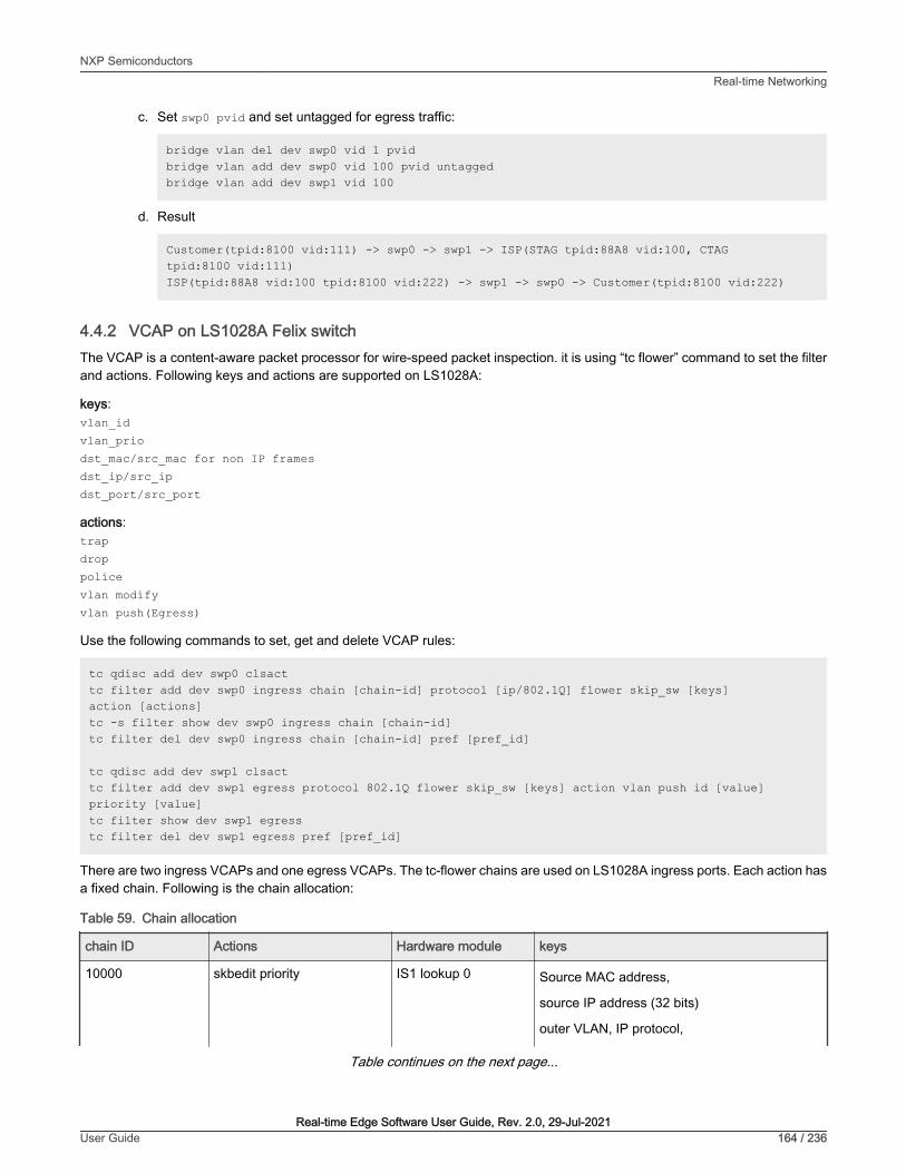
c. Set swp0 pvid and set untagged for egress traffic:
bridge vlan del dev swp0 vid 1 pvidbridge vlan add dev swp0 vid 100 pvid untaggedbridge vlan add dev swp1 vid 100
d. Result
Customer(tpid:8100 vid:111) -> swp0 -> swp1 -> ISP(STAG tpid:88A8 vid:100, CTAG tpid:8100 vid:111)ISP(tpid:88A8 vid:100 tpid:8100 vid:222) -> swp1 -> swp0 -> Customer(tpid:8100 vid:222)
4.4.2 VCAP on LS1028A Felix switchThe VCAP is a content-aware packet processor for wire-speed packet inspection. it is using “tc flower” command to set the filterand actions. Following keys and actions are supported on LS1028A:
keys:vlan_idvlan_priodst_mac/src_mac for non IP framesdst_ip/src_ipdst_port/src_port
actions:trapdroppolicevlan modifyvlan push(Egress)
Use the following commands to set, get and delete VCAP rules:
tc qdisc add dev swp0 clsacttc filter add dev swp0 ingress chain [chain-id] protocol [ip/802.1Q] flower skip_sw [keys] action [actions]tc -s filter show dev swp0 ingress chain [chain-id]tc filter del dev swp0 ingress chain [chain-id] pref [pref_id]
tc qdisc add dev swp1 clsacttc filter add dev swp1 egress protocol 802.1Q flower skip_sw [keys] action vlan push id [value] priority [value]tc filter show dev swp1 egresstc filter del dev swp1 egress pref [pref_id]
There are two ingress VCAPs and one egress VCAPs. The tc-flower chains are used on LS1028A ingress ports. Each action hasa fixed chain. Following is the chain allocation:
Table 59. Chain allocation
chain ID Actions Hardware module keys
10000 skbedit priority IS1 lookup 0 Source MAC address,
source IP address (32 bits)
outer VLAN, IP protocol,
Table continues on the next page...
NXP SemiconductorsReal-time Networking
Real-time Edge Software User Guide, Rev. 2.0, 29-Jul-2021User Guide 164 / 236

Table 59. Chain allocation (continued)
chain ID Actions Hardware module keys
source TCP/UDP ports.
11000 vlan pop; vlan modify IS1 lookup 1 Inner and outer VLAN,
source and destination IP addresses (32 bits),
IP protocol,
source and destination TCP/UDP ports.
12000 goto chain [PAG] IS1 lookup 2 Source MAC address,
source IP address (32 bits)
outer VLAN, IP protocol,
source TCP/UDP ports.
20000-20255 police IS2 lookup 0 Source and destination MAC address,
source and destination IP addresses (32 bits),
IP protocol,
source and destination TCP/UDP ports.
21000-21255 drop; trap; redirect IS2 lookup 1 Source and destination MAC address,
source and destination IP addresses (32 bits),
IP protocol,
source and destination TCP/UDP ports.
30000 gate; police PSFP destination MAC address and Vlan ID
Before using chains, users should register each chain and set chain pipeline order for a packet. The hardware ingress orderis: IS1->IS2->PSFP.
tc qdisc add dev swp0 clsacttc filter add dev swp0 ingress chain 0 pref 49152 flower skip_sw action goto chain 10000tc filter add dev swp0 ingress chain 10000 pref 49152 flower skip_sw action goto chain 11000tc filter add dev swp0 ingress chain 11000 pref 49152 flower skip_sw action goto chain 12000tc filter add dev swp0 ingress chain 12000 pref 49152 flower skip_sw action goto chain 20000tc filter add dev swp0 ingress chain 20000 pref 49152 flower skip_sw action goto chain 21000tc filter add dev swp0 ingress chain 21000 pref 49152 flower skip_sw action goto chain 30000
After registering the chain, add rules to the corresponding chain. following are the use cases for testing:
NXP SemiconductorsReal-time Networking
Real-time Edge Software User Guide, Rev. 2.0, 29-Jul-2021User Guide 165 / 236

Figure 37. VCAP test
1. Drop all frames from source IP 192.168.2.1.
tc filter add dev swp0 ingress chain 21000 protocol ip flower skip_sw src_ip 192.168.2.1 action drop
Set source IP as 192.168.2.1 and send IP package from TestCenter, package will be dropped on swp0.
2. Limit bandwidth of HTTP streams to 10 Mbps.
tc filter add dev swp0 ingress chain 20000 protocol ip flower skip_sw ip_proto tcp dst_port 80 action police rate 10Mbit burst 10000 action goto chain 21000
Send TCP package and set destination port as 80 on TestCenter, set the stream bandwidth to 1Gbit/s, we can get a10Mbits/s stream rate.
3. Filter frames that have a specific vlan tag (VID=1 and PCP=1). Then, modify the vlan tag (VID=2, PCP=2) and classifiedto QoS traffic class 2.
ip link set switch type bridge vlan_filtering 1tc filter add dev swp0 ingress chain 11000 protocol 802.1Q flower skip_sw vlan_id 1 vlan_prio 1 action vlan modify id 2 priority 2 action goto chain 12000bridge vlan add dev swp0 vid 2bridge vlan add dev swp1 vid 2
Set vid=1 and pcp=1 in vlan tag. Then, send IP package from TestCenter. Thus you can get a package with vid=2, pcp=2from swp1 on TestCenter.
NXP SemiconductorsReal-time Networking
Real-time Edge Software User Guide, Rev. 2.0, 29-Jul-2021User Guide 166 / 236

4. Push a specific vlan tag (vid=3, pcp=3) into frames (classified vid=2, pcp=2 in switch) egress from swp1.
tc qdisc add dev swp1 clsacttc filter add dev swp1 egress protocol 802.1Q flower skip_sw vlan_id 2 vlan_prio 2 action vlan push id 3 priority 3
Set vid=1 and pcp=1 in vlan tag, then send IP package from TestCenter, the frame will hit rule in usecase 3 and retag thevlan (vid=2, pcp=2). Thus, users can get a frame with vid=3, pcp=3 from swp1 on TestCenter.
5. Push double vlan tag(Q-in-Q) into frames egress to swp1.
ip link add dev br0 type bridgeip link set dev swp0 master br0ip link set dev swp1 master br0ip link set br0 type bridge vlan_filtering 1bridge vlan add dev swp0 vid 222bridge vlan add dev swp1 vid 222tc qdisc add dev swp1 clsacttc filter add dev swp1 egress protocol 802.1Q flower skip_sw \ vlan_id 222 vlan_prio 2 \ action vlan push id 200 priority 1 protocol 802.1AD \ action vlan push id 300 priority 3
Result: TX(tpid:8100 vid:222 pri:2) -> swp0 -> swp1 -> RX(S-TAG tpid:88A8 vid:200 pri:1, C-TAGtpid:8100 vid:300 pri:3)
6. Pop single or double vlan tag(Q-in-Q) from frames ingress from swp0.
ip link add dev br0 type bridgeip link set dev swp0 master br0ip link set dev swp1 master br0tc filter add dev swp0 ingress chain 11000 \ protocol 802.1ad flower \ vlan_id 111 vlan_prio 1 vlan_ethtype 802.1q \ cvlan_id 222 cvlan_prio 2 cvlan_ethtype ipv4 \ action vlan pop action goto chain 12000
Result: TX(S-TAG tpid:88A8 vid:111 pri:1, C-TAG tpid:8100 vid:222 pri:2) -> swp0 -> swp1 -> RX(TAGtpid:8100 vid:222 pri:2)
tc filter add dev swp0 ingress chain 11000 \ protocol 802.1ad flower \ vlan_id 111 vlan_prio 1 vlan_ethtype 802.1q \ cvlan_id 223 cvlan_prio 2 cvlan_ethtype ipv4 \ action vlan pop \ action vlan pop action goto chain 12000
Result: TX(S-TAG tpid:88A8 vid:111 pri:1, C-TAG tpid:8100 vid:223 pri:2) -> swp0 -> swp1 -> RX(receivedpackets without VLAN tag)
NXP SemiconductorsReal-time Networking
Real-time Edge Software User Guide, Rev. 2.0, 29-Jul-2021User Guide 167 / 236

Chapter 5Protocols5.1 EtherCATReal-time Edge supports the usage of EtherCAT ((Ethernet for Control Automation Technology) and integrates the IGH EtherCATmaster stack. EtherCAT is verified on NXP’s platforms.
5.1.1 IntroductionEtherCAT is an Ethernet-based fieldbus system, invented by BECKHOFF Automation. The protocol is standardized in IEC 61158and is suitable for both hard and soft real-time computing requirements in automation technology. The goal during developmentof EtherCAT was to apply Ethernet for automation applications requiring short data update times (also called cycle times; ≤ 100µs) with low communication jitter (for precise synchronization purposes; ≤ 1 µs) and reduced hardware costs.
• EtherCAT is Fast: 1000 dig. I/O: 30 µs, 100 slaves: 100 µs.
• EtherCAT is Ethernet: Standard Ethernet at I/O level.
• EtherCAT is Flexible: Star, line, drop, with or without switch.
• EtherCAT is Inexpensive: Ethernet is mainstream technology, therefore inexpensive.
• EtherCAT is Easy: everybody knows Ethernet, it is simple to use.
At present, the EtherCAT master supports the common open source code for SOEM of RT - LAB development (Simple OpenSource EtherCAT Master) and EtherLab, the IGH EtherCAT master. To use SOEM is simpler than to use the IGH EtherCATMaster, but IGH for the realization of the EtherCAT is more complete. For example, IGH supports more NIC. For more information,see https://rt-labs.com/ethercat/ and http://www.etherlab.org. The integration in Real-time Edge is IGH EtherCAT master.
5.1.2 IGH EtherCAT architectureThe components of the master environment are described below:
• Master module: This is the kernel module containing one or more EtherCAT master instances, the ‘Device Interface’ andthe ‘Application Interface’.
• Device modules: These are EtherCAT-capable Ethernet device driver modules that offer their devices to the EtherCATmaster via the device interface. These modified network drivers can handle network devices used for EtherCAT operationand ‘normal’ Ethernet devices in parallel. A master can accept a certain device and then, is able to send and receiveEtherCAT frames. Ethernet devices declined by the master module are connected to the kernel's network stack, as usual.
• Application: A program that uses the EtherCAT master (usually for cyclic exchange of process data with EtherCATslaves). These programs are not part of the EtherCAT master code, but require to be generated or written by the user.An application can request a master through the application interface. If this succeeds, it has the control over the master:It can provide a bus configuration and exchange process data. Applications can be kernel modules that use the kernelapplication interface directly. They also include user space programs, which use the application interface via the EtherCATlibrary or the RTDM library.
The following figure shows that IGH EtherCAT master architecture.
NXP Semiconductors
Real-time Edge Software User Guide, Rev. 2.0, 29-Jul-2021User Guide 168 / 236

Figure 38. IGH EtherCAT master architecture
5.1.3 EtherCAT protocolFollowing are the characteristics of the EtherCAT protocol:
• The EtherCAT protocol is optimized for process data and is transported directly within the standard IEEE 802.3 Ethernet frameusing Ethertype 0x88a4.
• The data sequence is independent of the physical order of the nodes in the network; addressing can be in any order.
• Broadcast, multicast, and communication between slaves is possible, but must be initiated by the master device.
• If IP routing is required, the EtherCAT protocol can be inserted into UDP/IP datagrams. This also enables any control withEthernet protocol stack to address EtherCAT systems.
• It does not support shortened frames.
The following figure shows the EtherCAT frame structure.
NXP SemiconductorsProtocols
Real-time Edge Software User Guide, Rev. 2.0, 29-Jul-2021User Guide 169 / 236

Figure 39. EtherCAT frame structure
5.1.4 IGH EtherCAT Device ModulesThere are two kinds of device drivers modules:
1. Native Ethernet Device Drivers
In Real-time Edge software, Only one native driver "ec_fec" is supplied , which could be used for the FEC MAC on i.MX 8M MiniEVK. This driver is not verified on other i.MX platforms in this release.
Note: the original Ethernet fec driver must be recompiled as a module by reconfiguring Linux with command "make menuconfig"when using ec_fec native driver.
2. Generic Ethernet Device Driver
The Generic driver uses the lower layers of the Linux network stack to connect to the hardware, independently of the actualhardware driver. So it can be used to all the platforms Real-time Edge supportes. But the disadvantage is that the performanceis a little worse than the native driver, because the Ethernet frame date have to traverse the Linux network stack.
5.1.5 IGH EtherCAT integration and setupThis section describes how to build the IGH stack and how to Setup the EtherCAT service.
5.1.5.1 Building IGH EtherCAT
IGH EtherCAT package is enabled on Real-time Edge images by default. The native driver ec_fec module is enabled by defaultfor i.MX 8M Mini EVK. For others platform, only generic driver is supported.
5.1.5.2 IGH EtherCAT setup
1. Configuration
The configure file /etc/ethercat.conf needs to be configured for the first time as below:
• Set "MASTER0_DEVICE" to the MAC address of the Ethernet Card, which will be used as EtherCAT network port. Forexample:
NXP SemiconductorsProtocols
Real-time Edge Software User Guide, Rev. 2.0, 29-Jul-2021User Guide 170 / 236

MASTER0_DEVICE="00:04:9f:07:11:a6"
• Specify the device driver modules for the EtherCAT device selected above by MAC address.
DEVICE_MODULES="generic"
For i.MX 8M Mini EVK, the option "fec" is available. But note that the original Ethernet fec driver must be compiled as a modules byreconfiguring Linux menuconfig if "fec" is selected. On Real-time Edge, the fec Ethernet driver has been configured as a moduleby default for i.MX 8M Mini EVK.
2. Start the daemon
Use the below command to start IGH-EtherCAT daemon:
$ ethercatctl start
Also, the below commands are used to stop or restart it.
$ ethercatctl stop$ ethercatctl restart
Note: If the generic driver is used, make sure using "ifconfig <ethX> up" command to enable the network Card.
IGH provides a powerful auxiliary command-line tool, named “ethercat”. it is can be used to query the master and all slavesinformation and status. The usage is as below:
Usage: ethercat <COMMAND> [OPTIONS] [ARGUMENTS] Commands (can be abbreviated): alias Write alias addresses. config Show slave configurations. crc CRC error register diagnosis. cstruct Generate slave PDO information in C language. data Output binary domain process data. debug Set the master's debug level. domains Show configured domains. download Write an SDO entry to a slave. eoe Display Ethernet over EtherCAT statictics. foe_read Read a file from a slave via FoE. foe_write Store a file on a slave via FoE. graph Output the bus topology as a graph. master Show master and Ethernet device information. pdos List Sync managers, PDO assignment and mapping. reg_read Output a slave's register contents. reg_write Write data to a slave's registers. rescan Rescan the bus. sdos List SDO dictionaries. sii_read Output a slave's SII contents. sii_write Write SII contents to a slave. slaves Display slaves on the bus. soe_read Read an SoE IDN from a slave. soe_write Write an SoE IDN to a slave. states Request application-layer states. upload Read an SDO entry from a slave. version Show version information. xml Generate slave information XML.
3. Enable the systemd IGH-EtherCAT service
NXP SemiconductorsProtocols
Real-time Edge Software User Guide, Rev. 2.0, 29-Jul-2021User Guide 171 / 236
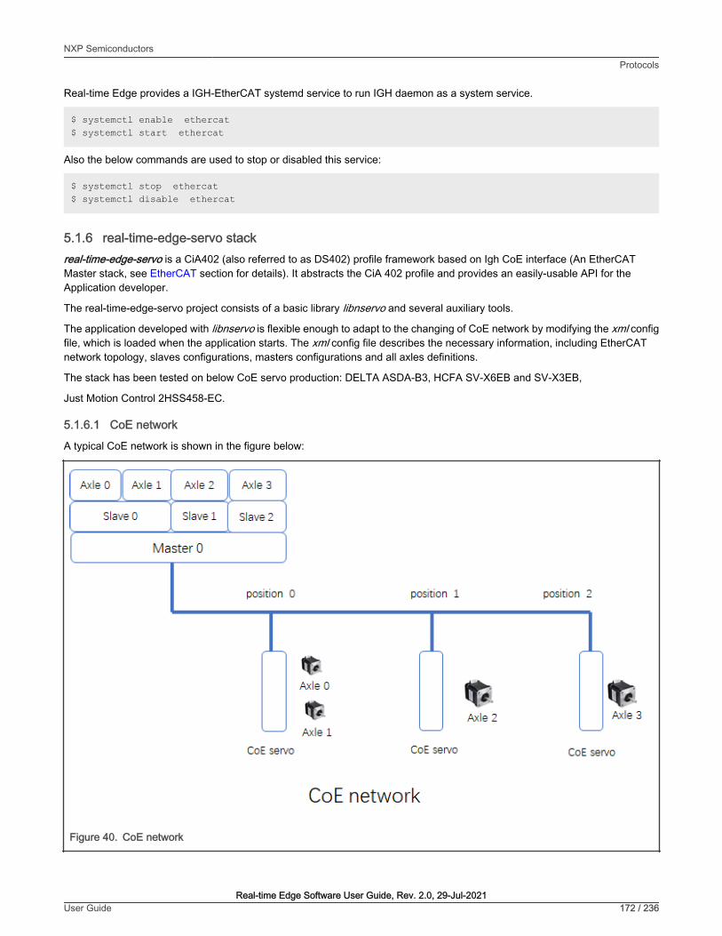
Real-time Edge provides a IGH-EtherCAT systemd service to run IGH daemon as a system service.
$ systemctl enable ethercat$ systemctl start ethercat
Also the below commands are used to stop or disabled this service:
$ systemctl stop ethercat$ systemctl disable ethercat
5.1.6 real-time-edge-servo stackreal-time-edge-servo is a CiA402 (also referred to as DS402) profile framework based on Igh CoE interface (An EtherCATMaster stack, see EtherCAT section for details). It abstracts the CiA 402 profile and provides an easily-usable API for theApplication developer.
The real-time-edge-servo project consists of a basic library libnservo and several auxiliary tools.
The application developed with libnservo is flexible enough to adapt to the changing of CoE network by modifying the xml configfile, which is loaded when the application starts. The xml config file describes the necessary information, including EtherCATnetwork topology, slaves configurations, masters configurations and all axles definitions.
The stack has been tested on below CoE servo production: DELTA ASDA-B3, HCFA SV-X6EB and SV-X3EB,
Just Motion Control 2HSS458-EC.
5.1.6.1 CoE network
A typical CoE network is shown in the figure below:
Figure 40. CoE network
NXP SemiconductorsProtocols
Real-time Edge Software User Guide, Rev. 2.0, 29-Jul-2021User Guide 172 / 236

There are three CoE servos on this network and we name them slave x as the position they are. Each CoE servo could have morethen one axle. The libnservo then initiates the CoE network and encapsulates the detail of network topology into axle nodes. Sothe developer could focus on the each axle operation without taking care of the network topology.
5.1.6.2 Libnservo architecture
real-time-edge-servo is running on top of Igh EtherCAT stack. And the Igh stack provides CoE communication mechanisms -Mailbox and Process Data. Using these mechanisms, real-time-edge-servo could access the CiA Object Dictionary located onCoE servo.
Figure 41. Libnservo architecture
Control task initiates the master, all slaves on the CoE network and registers all PDOs to Igh stack, then constructs a data structureto describe each axle. Finally, the control task creates a task to run the user task periodically.
5.1.6.3 real-time-edge-servo Xml configuration
This section focuses on how the xml config file describes a CoE network.
The skeleton of XML config is shown as in figure below:
<?xml version="1.0" encoding="utf-8"?><Config Version="1.2"> <PeriodTime>#10000000</PeriodTime>
NXP SemiconductorsProtocols
Real-time Edge Software User Guide, Rev. 2.0, 29-Jul-2021User Guide 173 / 236

<MaxSafeStack>#8192</MaxSafeStack> <master_status_update_freq>#1</master_status_update_freq> <slave_status_update_freq>#1</slave_status_update_freq> <axle_status_update_freq>#1</axle_status_update_freq> <sync_ref_update_freq>#2</sync_ref_update_freq> <sched_priority>#90</sched_priority> <sched_policy>#SCHED_FIFO</sched_policy> <Masters> <Master> ... <\Master> <Master> ... <\Master> <\Master> <Axles> <Axle> ... <\Axle> <Axle> ... <\Axle> <\Axles> </Config>
• All config elements must be inside the <Config> element.
• All config elements shown above are mandatory.
• The numerical value started with # means that it is a decimal value.
• The numerical value started with#x means that it is a hexadecimal value.
• <PeriodTime> element means that the period of control task is 10ms.
• <MaxSafeStack> means the stack size, and it is an estimated value. 8K is enough to satisfy most application.
• <master_status_update_freq> element means the frequency of masters status update. the value #x means update themasters status every task period.
• <slave_status_update_freq> element means the frequency of slaves status update. the value #1 means update the slavesstatus every task period.
• <axle_status_update_freq> element means the frequency of axles status update. the value #1 means update the axles statusevery task period.
• <sync_ref_update_freq> element means the frequency of reference clock update. the value #2 means update the axles statusevery two task period.
• <sched_policy > element specifies which schedule policy for user task.
• <sched_priority> element means the priority of the user task.
• <Masters> element could contain more than one Master element . For most cases, there is only one master on a host.
• <Axles> element could contain more than one Axle element, which is the developer really care about.
5.1.6.3.1 Master element
As CoE network section shown, the Master could has many slaves, so the Master element will consist of some Slave elements.
<Master> <Master_index>#0</Master_index> <Reference_clock>#0</Reference_clock>
NXP SemiconductorsProtocols
Real-time Edge Software User Guide, Rev. 2.0, 29-Jul-2021User Guide 174 / 236
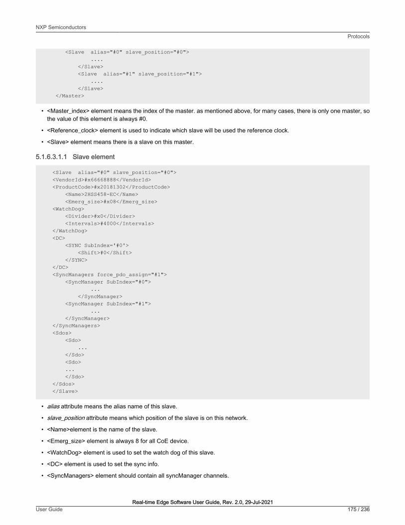
<Slave alias="#0" slave_position="#0"> .... </Slave> <Slave alias="#1" slave_position="#1"> .... </Slave> </Master>
• <Master_index> element means the index of the master. as mentioned above, for many cases, there is only one master, sothe value of this element is always #0.
• <Reference_clock> element is used to indicate which slave will be used the reference clock.
• <Slave> element means there is a slave on this master.
5.1.6.3.1.1 Slave element
<Slave alias="#0" slave_position="#0"> <VendorId>#x66668888</VendorId> <ProductCode>#x20181302</ProductCode> <Name>2HSS458-EC</Name> <Emerg_size>#x08</Emerg_size> <WatchDog> <Divider>#x0</Divider> <Intervals>#4000</Intervals> </WatchDog> <DC> <SYNC SubIndex='#0'> <Shift>#0</Shift> </SYNC> </DC> <SyncManagers force_pdo_assign="#1"> <SyncManager SubIndex="#0"> ... </SyncManager> <SyncManager SubIndex="#1"> ... </SyncManager> </SyncManagers> <Sdos> <Sdo> ... </Sdo> <Sdo> ... </Sdo> </Sdos> </Slave>
• alias attribute means the alias name of this slave.
• slave_position attribute means which position of the slave is on this network.
• <Name>element is the name of the slave.
• <Emerg_size> element is always 8 for all CoE device.
• <WatchDog> element is used to set the watch dog of this slave.
• <DC> element is used to set the sync info.
• <SyncManagers> element should contain all syncManager channels.
NXP SemiconductorsProtocols
Real-time Edge Software User Guide, Rev. 2.0, 29-Jul-2021User Guide 175 / 236

• <Sdos> element contains the default value we want to initiate by SDO channel.
5.1.6.3.1.1.1 SyncManagers ElementFor a CoE device, there are generally four syncManager channels.
• SM0: Mailbox output
• SM1: Mailbox input
• SM2: Process data outputs
• SM3: process data inputs
<SyncManager SubIndex="#2"> <Index>#x1c12</Index> <Name>Sync Manager 2</Name> <Dir>OUTPUT</Dir> <Watchdog>ENABLE</Watchdog> <PdoNum>#1</PdoNum> <Pdo SubIndex="#1"> <Index>#x1600</Index> <Name>RxPdo 1</Name> <Entry SubIndex="#1"> ... </Entry> <Entry SubIndex="#2"> ... </Entry> </Pdo> </SyncManager>
• <Index> element is the object address.
• <Name> is a name of this syncmanager channel.
• <Dir> element is the direction of this syncmanager channel.
• <Watchdog> is used to set watchdog of this syncmanager channel.
• <PdoNum> element means how many PDO we want to set.
• <Pdo SubIndex="#1> element contains the object dictionary entry we want to mapped.
— <Index> PDO address.
— <Name> PDO name
— <Entry> the object dictionary we want to mapped.
The Entry element is used to describe a object dictionary we want to mapped.
<Entry SubIndex="#1"> <Index>#x6041</Index> <SubIndex>#x0</SubIndex> <DataType>UINT</DataType> <BitLen>#16</BitLen> <Name>statusword</Name> </Entry>
NXP SemiconductorsProtocols
Real-time Edge Software User Guide, Rev. 2.0, 29-Jul-2021User Guide 176 / 236

5.1.6.3.1.1.2 Sdo elementThe Sdo element is used to set the default value of a object dictionary.
<Sdo> <Index>#x6085</Index> <Subindex>#x0</Subindex> <value>#x1000</value> <BitLen>#32</BitLen> <DataType>DINT</DataType> <Name>Quick_stop_deceleration</Name> </Sdo>
The element shown in figure above means set the Object Dictionary "6085" to 0x1000.
5.1.6.3.2 Axle element
<Axle master_index='#0' slave_position="#0" AxleIndex="#0" AxleOffset="#0"> <Mode>pp</Mode> <Name>x-axle</Name> <reg_pdo> ... </reg_pdo> <reg_pdo> ... </reg_pdo> </Axle>
• master_index attribute indicates which master this axle belong to.
• slave_position attribute indicates which slave this axle belong to.
• AxleOffset attribute indicates which axle this axle is on the slave. As mentioned above, a CoE slave could have more then onaxle . If this axle is the second axle on the slave, set AxleOffset="#1" .
• <Mode> means which mode this axle will work on.
• <Name> is the name of this axle.
• <reg_pdo> is the PDO entry we want to register.
reg_pdo element
<reg_pdo> <Index>#x606c</Index> <Subindex>#x0</Subindex> <Name></Name> </reg_pdo>
5.1.6.4 Test
5.1.6.4.1 Hardware preparation
• A CoE servo system
A CoE servo system includes a CoE servo and a motor. In this test, '2HSS458-EC' servo system shown as in figure belowwill be used.
• A board supported by Real-time Edge
In this test, LS1046ARDB will be used.
NXP SemiconductorsProtocols
Real-time Edge Software User Guide, Rev. 2.0, 29-Jul-2021User Guide 177 / 236
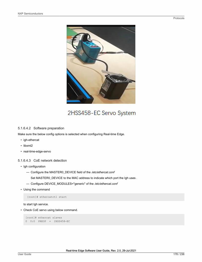
5.1.6.4.2 Software preparation
Make sure the below config options is selected when configuring Real-time Edge.
• igh-ethercat
• libxml2
• real-time-edge-servo
5.1.6.4.3 CoE network detection
• Igh configuration
— Configure the MASTER0_DEVICE field of the /etc/ethercat.conf
Set MASTER0_DEVICE to the MAC address to indicate which port the Igh uses .
— Configure DEVICE_MODULES="generic" of the /etc/ethercat.conf
• Using the command
[root]# ethercatctl start
to start Igh service.
• Check CoE servo using below command.
[root]# ethercat slaves0 0:0 PREOP + 2HSS458-EC
NXP SemiconductorsProtocols
Real-time Edge Software User Guide, Rev. 2.0, 29-Jul-2021User Guide 178 / 236

5.1.6.4.4 Start test
Note: The Position encoder resolution and Velocity encoder resolution of "2HSS458-EC" servo system are both 4000 . It meansthe ratio of encoder increments per motor revolution.
• Profile Position mode test
— Start the test service as below.
[root]# nservo_run -f /root/nservo_example/hss248_ec_config_pp.xml &
— Check whether the status of the slave has been transferred from "PREOP" to "OP".
[root]# ethercat slaves0 0:0 OP + 2HSS458-EC
— Check whether the phase of the master has been transferred from "Idle" to "Operation".
[root]# ethercat master | grep Phase Phase: Operation
— Run below commands to test whether the motor works.
◦ Get current mode of axle 0.
[root]# nservo_client -a 0 -c get_modeget_mode of the axle 0 : Profile Position Mode
◦ Get current position of axle 0.
[root]# nservo_client -a 0 -c get_positionget_current_position of the axle 0 : 0
◦ Get the profile speed of axle 0.
[root# nservo_client -a 0 -c get_profile_speedget_profile_speed of the axle 0 : 800000
The value 800000 means 200 revolutions per second.
◦ Set profile speed of axle 0.
[root]# nservo_client -a 0 -c set_profile_speed:20000set_profile_speed of the axle 0 : 20000
Set profile speed to 5 revolutions per second.
◦ Set target position of axle 0
[root]# nservo_client -c set_position:400000set_position of the axle 0 : 400000
The value 400000 means that the motor will turn 100 rounds.
(target_position:400000 - current_position:0) / 4000 = 100
◦ Get current speed of axle 0
[root]# nservo_client -a 0 -c get_speedget_speed of the axle 0 : 19999
NXP SemiconductorsProtocols
Real-time Edge Software User Guide, Rev. 2.0, 29-Jul-2021User Guide 179 / 236
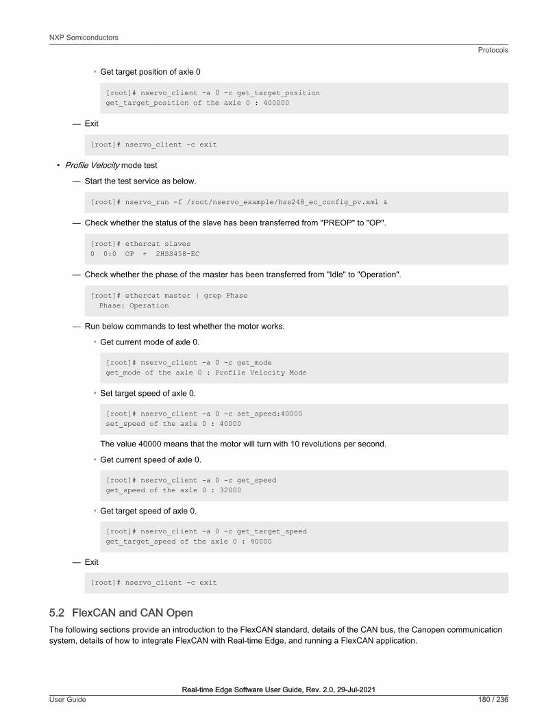
◦ Get target position of axle 0
[root]# nservo_client -a 0 -c get_target_positionget_target_position of the axle 0 : 400000
— Exit
[root]# nservo_client -c exit
• Profile Velocity mode test
— Start the test service as below.
[root]# nservo_run -f /root/nservo_example/hss248_ec_config_pv.xml &
— Check whether the status of the slave has been transferred from "PREOP" to "OP".
[root]# ethercat slaves0 0:0 OP + 2HSS458-EC
— Check whether the phase of the master has been transferred from "Idle" to "Operation".
[root]# ethercat master | grep Phase Phase: Operation
— Run below commands to test whether the motor works.
◦ Get current mode of axle 0.
[root]# nservo_client -a 0 -c get_modeget_mode of the axle 0 : Profile Velocity Mode
◦ Set target speed of axle 0.
[root]# nservo_client -a 0 -c set_speed:40000set_speed of the axle 0 : 40000
The value 40000 means that the motor will turn with 10 revolutions per second.
◦ Get current speed of axle 0.
[root]# nservo_client -a 0 -c get_speedget_speed of the axle 0 : 32000
◦ Get target speed of axle 0.
[root]# nservo_client -a 0 -c get_target_speedget_target_speed of the axle 0 : 40000
— Exit
[root]# nservo_client -c exit
5.2 FlexCAN and CAN OpenThe following sections provide an introduction to the FlexCAN standard, details of the CAN bus, the Canopen communicationsystem, details of how to integrate FlexCAN with Real-time Edge, and running a FlexCAN application.
NXP SemiconductorsProtocols
Real-time Edge Software User Guide, Rev. 2.0, 29-Jul-2021User Guide 180 / 236
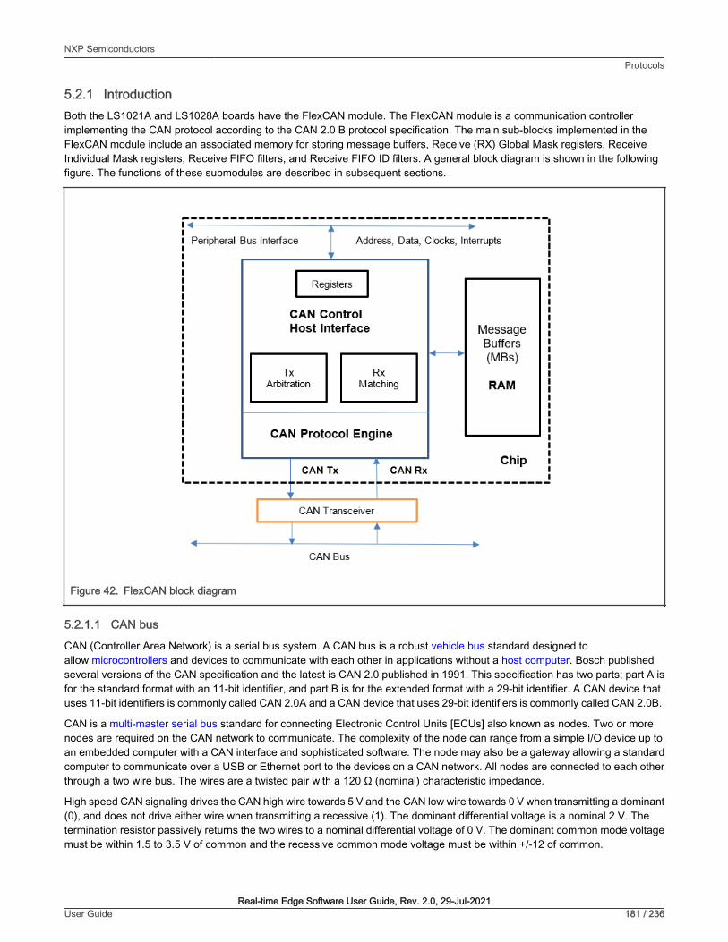
5.2.1 IntroductionBoth the LS1021A and LS1028A boards have the FlexCAN module. The FlexCAN module is a communication controllerimplementing the CAN protocol according to the CAN 2.0 B protocol specification. The main sub-blocks implemented in theFlexCAN module include an associated memory for storing message buffers, Receive (RX) Global Mask registers, ReceiveIndividual Mask registers, Receive FIFO filters, and Receive FIFO ID filters. A general block diagram is shown in the followingfigure. The functions of these submodules are described in subsequent sections.
Figure 42. FlexCAN block diagram
5.2.1.1 CAN bus
CAN (Controller Area Network) is a serial bus system. A CAN bus is a robust vehicle bus standard designed toallow microcontrollers and devices to communicate with each other in applications without a host computer. Bosch publishedseveral versions of the CAN specification and the latest is CAN 2.0 published in 1991. This specification has two parts; part A isfor the standard format with an 11-bit identifier, and part B is for the extended format with a 29-bit identifier. A CAN device thatuses 11-bit identifiers is commonly called CAN 2.0A and a CAN device that uses 29-bit identifiers is commonly called CAN 2.0B.
CAN is a multi-master serial bus standard for connecting Electronic Control Units [ECUs] also known as nodes. Two or morenodes are required on the CAN network to communicate. The complexity of the node can range from a simple I/O device up toan embedded computer with a CAN interface and sophisticated software. The node may also be a gateway allowing a standardcomputer to communicate over a USB or Ethernet port to the devices on a CAN network. All nodes are connected to each otherthrough a two wire bus. The wires are a twisted pair with a 120 Ω (nominal) characteristic impedance.
High speed CAN signaling drives the CAN high wire towards 5 V and the CAN low wire towards 0 V when transmitting a dominant(0), and does not drive either wire when transmitting a recessive (1). The dominant differential voltage is a nominal 2 V. Thetermination resistor passively returns the two wires to a nominal differential voltage of 0 V. The dominant common mode voltagemust be within 1.5 to 3.5 V of common and the recessive common mode voltage must be within +/-12 of common.
NXP SemiconductorsProtocols
Real-time Edge Software User Guide, Rev. 2.0, 29-Jul-2021User Guide 181 / 236

Figure 43. High speed CAN signaling
Figure 44. Base frame format
Figure 45. High speed CAN network
5.2.1.2 CANopen
CANopen is a CAN-based communication system. It comprises higher-layer protocols and profile specifications. CANopen hasbeen developed as a standardized embedded network with highly flexible configuration capabilities. Today it is used in variousapplication fields, such as medical equipment, off-road vehicles, maritime electronics, railway applications, or building automation.
CANopen provides several communication objects, which enable device designers to implement desired network behavior intoa device. With these communication objects, device designers can offer devices that can communicate process data, indicatedevice-internal error conditions or influence and control the network behavior. As CANopen defines the internal device structure,the system designer knows exactly how to access a CANopen device and how to adjust the intended device behavior.
• CANopen lower layers
CANopen is based on a data link layer according to ISO 11898-1. The CANopen bit timing is specified in CiA 301 and allowsthe adjustment of data rates from 10 kbit/s to 1000 kbit/s. Although all specified CAN-ID addressing schemata are based on
NXP SemiconductorsProtocols
Real-time Edge Software User Guide, Rev. 2.0, 29-Jul-2021User Guide 182 / 236

the 11-bit CAN-ID, CANopen supports the 29-bit CAN-ID as well. Nevertheless, CANopen does not exclude other physicallayer options.
• Internal device architecture
A CANopen device consists of three logical parts. The CANopen protocol stack handles the communication via the CANnetwork. The application software provides the internal control functionality. The CANopen object dictionary interfaces theprotocol as well as the application software. It contains indices for all used data types and stores all communication andapplication parameters. The CANopen object dictionary is most important for CANopen device configuration and diagnostics.
• CANopen protocols
— SDO protocol
— PDO protocol
— NMT protocol
— Special function protocols
— Error control protocols
The following figure shows the CANopen architecture.
Figure 46. CANopen architecture
NXP SemiconductorsProtocols
Real-time Edge Software User Guide, Rev. 2.0, 29-Jul-2021User Guide 183 / 236

5.2.2 FlexCAN integration in Real-time EdgeFor LS1021A, there are four CAN controllers. Two CAN controllers (CAN3 and CAN4) are used to communicate with each other.CAN4 is assigned to core0, which runs Linux and CANOpen as master node, whereas CAN3 is assigned to core1, which runs theBareMetal and CANOpen as slave node. For LS1028A, there are two CAN controllers, CAN1 and CAN2, and both of them areused in LS1028ARDB board.
5.2.2.1 LS1021AIOT CAN resource allocation
This section describes steps for assigning CAN4 to Linux and CAN3 to BareMetal core, and how to change or configure it. Theseexamples assume that CAN1 and CAN2 are not enabled, and the pins of CAN1 and CAN2 are used by other IPs.
1. Assigning CAN4 to Linux
In Linux, the port is allocated through the DTS file. DTS file path is industry-linux/arch/arm/boot/dts/ls1021a-iot.dts. Content related to CAN ports is as follows:
/* CAN3 port */ &can2 { status = " disabled "; }; /* CAN4 port */ &can3 { status = "okay"; };
2. Assigning CAN3 to BareMetal
In BareMetal, the port is allocated through the flexcan.c file. The flexcan.c path is industry-uboot/drivers/flexcan/flexcan.c. In this file, users should define the following variables:
a. struct can_bittiming_t flexcan3_bittiming = CAN_BITTIM_INIT(CAN_500K);
Set bit timing and baud rate (500K) of the CAN port.
NOTE
b. struct can_ctrlmode_t flexcan3_ctrlmode
struct can_ctrlmode_t flexcan3_ctrlmode ={ .loopmode = 0, /* Indicates whether the loop mode is enabled */ .listenonly = 0, /* Indicates whether the only-listen mode is enabled */ .samples = 0, .err_report = 1, };
c. struct can_init_t flexcan3
struct can_init_t flexcan3 = { .canx = CAN3, /* Specify CAN port */ .bt = &flexcan3_bittiming, .ctrlmode = &flexcan3_ctrlmode, .reg_ctrl_default = 0, .reg_esr = 0};
d. Optional parameters
NXP SemiconductorsProtocols
Real-time Edge Software User Guide, Rev. 2.0, 29-Jul-2021User Guide 184 / 236

• CAN port
#define CAN3 ((struct can_module *)CAN3_BASE)#define CAN4 ((struct can_module *)CAN4_BASE)
• Baud rate
#define CAN_1000K 10#define CAN_500K 20#define CAN_250K 40#define CAN_200K 50#define CAN_125K 80#define CAN_100K 100#define CAN_50K 200#define CAN_20K 500#define CAN_10K 1000#define CAN_5K 2000
5.2.2.2 Introducing the function of CAN example code
CAN example code supports the CANopen protocol. It mainly implements three parts of functions: network manage function(NMT protocol), service data transmission function (SDO protocol), and process data transmission function (PDO protocol). NMTprotocol can manage and monitor slave nodes, include heart beat message. SDO protocol can transmit single or block data. ThePDO protocol can transmit process data that requires real time.
CAN example calls the CANopen interfaces, described in the table below:
Table 60. CAN Net APIs and their description
API name (type) Description
UNS8 canReceive_driver (CAN_HANDLE fd0, Message * m) SocketCAN receives CAN messages
• fd0 – SocketCAN handle
• m – Receive buffer
UNS8 canSend_driver (CAN_HANDLE fd0, Message const* m)
SocketCAN sends CAN messages
• fd0 – SocketCAN handle
• m – CAN message to be sent
void setNodeId(CO_Data* d, UNS8 nodeId) Set this node id value.
• d – object dictionary
• nodeId – id value (up to 127)
UNS8 setState(CO_Data* d, e_nodeState newState) Set node state
• d – object dictionary
• newState – The state that needs to be set
Returns 0 if OK, > 0 on error
void canDispatch(CO_Data* d, Message *m) CANopen handles data frames that CAN receive.
Table continues on the next page...
NXP SemiconductorsProtocols
Real-time Edge Software User Guide, Rev. 2.0, 29-Jul-2021User Guide 185 / 236

Table 60. CAN Net APIs and their description (continued)
API name (type) Description
• d – object dictionary
• m – Received CAN message
void timerForCan(void) CANopen virtual clock counter.
UNS8 sendPDOrequest (CO_Data * d, UNS16 RPDOIndex) Master node requests slave node to feedback specified data.
• d – object dictionary
• RPDOIndex – index value of specified data
UNS8 readNetworkDictCallback (CO_Data* d, UNS8nodeId, UNS16 index, UNS8 subIndex, UNS8 dataType,SDOCallback_t Callback, UNS8 useBlockMode)
The master node gets the specified data from the slave node.
• d – object dictionary
• nodeId – the id value of slave node
• index – the index value of the specified data
• subIndex – the subindex value of the specified data
• dataType – the data type of the specified data
• Callback – callback function
• useBlockMode – specifies whether it is ablock transmission
UNS8 writeNetworkDictCallBack (CO_Data* d, UNS8 nodeId,UNS16 index, UNS8 subIndex, UNS32 count, UNS8 dataType,void *data, SDOCallback_t Callback, UNS8 useBlockMode)
The master node sets the specified data to the slave node.
• d – object dictionary
• nodeId – the id value of slave node
• index – the index value of the specified data
• subIndex – the subindex value of the specified data
• count – the length of the specified data
• dataType – the data type of the specified data
• Callback – callback function
• useBlockMode – specifies whether it is ablock transmission
5.2.3 Running a CAN applicationThe following sections describe the hardware and software preparation steps for running a CAN application. The hardwarepreparation is described separately for the LS1021A-IoT and LS1028ARDB, but the sections Compiling the CANopen-appbinary for the master node, Running the CANopen application, and Running the SocketCAN commands are applicable to bothLS1021A-IoT and LS1028A platforms.
5.2.3.1 Hardware preparation for LS1021-IoT
For LS1021-IoT, the list of hardware required for implementing the FlexCAN demo is as follows:
• LS1021A-IoT boards
• Two CAN hardware interfaces (for example, CAN3 and CAN4 for LS1021A-IoT)
NXP SemiconductorsProtocols
Real-time Edge Software User Guide, Rev. 2.0, 29-Jul-2021User Guide 186 / 236

• Two CAN transceivers (for example: TJA1050 )
Figure 47. Hardware diagram for the FlexCan demo
— Line1 and line3 are 5.0 V.
— Line2 and line4 are GND.
— Line5 is CAN3 TX.
— Line6 is CAN3 RX.
— Line7 is CAN4 RX.
— Line8 is CAN4 TX.
NOTE
NXP SemiconductorsProtocols
Real-time Edge Software User Guide, Rev. 2.0, 29-Jul-2021User Guide 187 / 236
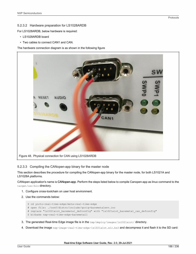
5.2.3.2 Hardware preparation for LS1028ARDB
For LS1028ARDB, below hardware is required:
• LS1028ARDB board
• Two cables to connect CAN1 and CAN.
The hardware connection diagram is as shown in the following figure
Figure 48. Physical connection for CAN using LS1028ARDB
5.2.3.3 Compiling the CANopen-app binary for the master node
This section describes the procedure for compiling the CANopen-app binary for the master node, for both LS1021A andLS1028A platforms.
CANopen application's name is CANopen-app. Perform the steps listed below to compile Canopen-app as linux command to thetarget/usr/bin directory.
1. Configure cross-toolchain on user host environment.
2. Use the commands below:
$ cd yocto-real-time-edge/meta-real-time-edge# open file: ./conf/distro/include/qoriq-baremetalenv.inc# replace "ls1021aiot_baremetal_defconfig" with "ls1021aiot_baremetal_can_defconfig"$ bitbake nxp-real-time-edge-baremetall
3. The generated Real-time Edge image file is in the tmp/deploy/images/ls1021aiot/ directory.
4. Download the image nxp-image-real-time-edge-ls1021aiot.wic.bz2 and decompress it and flash it to the SD card:
NXP SemiconductorsProtocols
Real-time Edge Software User Guide, Rev. 2.0, 29-Jul-2021User Guide 188 / 236

In U-Boot mode, first run the tftp command for downloading nxp-image-real-time-edge-ls1021aiot.wic to the buffer. Then,run the mmc command for downloading the nxp-image-real-time-edge-ls1021aiot.wic to SD card.
• The following options are displayed only when the canfestival option is set to Y.
• Linux uses the SocketCAN interface, so the driveroption selects the socket.
• The following additional configure options can be configured in the config.h file of CANopen:
Parameter description:
— --SDO_MAX_LENGTH_TRANSFER: Sets buffer size of SDO protocol.
— -- SDO_BLOCK_SIZE: Sets the maximum number of frames that can be sent by SDO blocktransport protocol.
— --SDO_MAX_SIMULTANEOUS_TRANSFERS: Sets the number of SDO modules.
• Install binary application to filesystem, if theinstall examples option is set to Y.
NOTE
5.2.3.4 Running the CANopen application
This section describes the procedure for running the CANopen-app application. Only the LS1021A platforms supportthis application.
1. First, boot the LS1021A-IoT board.
2. Waiting for the BareMetal core to output below information:
Note: the CANopen protocol starts to run!=>
3. Then, run the CANopen-app command in any directory in Linux prompt. While executing this command, first run thetest code.
4. After the test code is completed, user can implement the required instructions. The command CANopen-app executionprocess steps are described below:
a. First, indicate whether the CAN interface has opened successfully. All commands are dynamically registered. Then,indicate whether the command was registered successfully.
• Command registration log
Command Registration Log:[root@]# CANopen-app[ 80.899975] IPv6: ADDRCONF(NETDEV_CHANGE): can0: link becomes readyNote: open the CAN interface successfully!"can_quit" command: register OK!"setState" command: register OK!"showPdo" command: register OK!"requestPdo" command: register OK!"sdo" command: register OK!"" command: register OK!"test_startM" command: register OK!"test_sdoSingle" command: register OK!"test_sdoSingleW" command: register OK!"test_sdoBlock" command: register OK!"test_showPdoCyc" command: register OK!"test_showpdoreq" command: register OK!"test_requestpdo" command: register OK!
b. There are nine test code in total, tests 1 to 9. Test code details are shown in the test log.
NXP SemiconductorsProtocols
Real-time Edge Software User Guide, Rev. 2.0, 29-Jul-2021User Guide 189 / 236

• Test code log “---test---” indicates that the test code begins.
• Firstly, the execution rights of the SDO and PDO protocol are explained.
• The tests 1~4 are SDO protocol test code. After starting the CANopen master node, it automatically enters intoinitialization and pre-operation mode.
• The test5 is a test code that master node enters the operation mode and starts all slave nodes.
• The tests 6~9 are PDO protocol test code.
Test Code Log:------------------------- test ---------------------------Note: Test code start execute... SDO protocol is valid in preoperation mode, but PDO protocol is invalid! SDO and PDO protocol are both valid in operation mode! Console is invalid when testing!----------------------------------------------------------Note: test1--Read slave node single data by SDO.Note: master node initialization is complete!Note: master node entry into the preOperation mode!Note: Alarm timer is running!Note: slave node "0x02" entry into "Initialisation" state!----------------------------------------------------------Note: test2--Write 0x2CD5 to slave node by SDO.Note: Master write a data to 0x02 node successfully.----------------------------------------------------------Note: test3--Read slave node single data by SDO again.Note: reveived data is 0x2CD5----------------------------------------------------------Note: test4--Read slave node block data by SDO.---------------- text ------------------Note: reveived string ==>CANopen is a CAN-based communication system.It comprises higher-layer protocols and profile specifications.CANopen has been developed as a standardized embedded network with highly flexible configuration capabilities.It was designed originally for motion-oriented machine control systems, such as handling systems.Today it is used in various application fields, such as medical equipment, off-road vehicles, maritime electronics, railway applications, or building automation.
--------------------------------------------------------------------------------------------------Note: test5--Master node entry operation mode, and start slave nodes!Note: master node entry into the operation mode,and start all slave nodes!----------------------------------------------------------Note: test6--Master node show requested PDO data.Note: Rpdo4 data is " "----------------------------------------------------------Note: test7--Master node request PDO data.----------------------------------------------------------Note: test8--Master node show requested PDO data.Note: Rpdo4 data is "require"Note: slave node "0x02" entry into "Operational" state!----------------------------------------------------------Note: test9--Master node show received cycle PDO data.Note: Rpdo2 data is " cycle"----------------------------------------------------------
NXP SemiconductorsProtocols
Real-time Edge Software User Guide, Rev. 2.0, 29-Jul-2021User Guide 190 / 236

tests 1 to 9 are not commands.
NOTE
c. After the test code is executed, it automatically prints the list of commands. Num00~06 are normal commands. Afterexecuting these instructions without parameters, the instruction usage is displayed. Num08~14 are test commands.All test commands except num10 have no parameters. Argument of Num10 is a 16-bit integer.
• Now the user can execute any command in the command list.
Command List
Command List:------------------------------------------------------------------------- num | command | introduction------------------------------------------------------------------------- 00 | ctrl_quit | console thread exit!------------------------------------------------------------------------- 01 | help | command list------------------------------------------------------------------------- 02 | can_quit | exit CANopen thread------------------------------------------------------------------------- 03 | setState | set the CANopen node state------------------------------------------------------------------------- 04 | showPdo | show the data of RPDO------------------------------------------------------------------------- 05 | requestPdo | request the data of RPDO------------------------------------------------------------------------- 06 | sdo | read/write one entry by SDO protocol------------------------------------------------------------------------- 07 | | ------------------------------------------------------------------------- 08 | test_startM | test -- Start master------------------------------------------------------------------------- 09 | test_sdoSingle | test -- Read slave node single data------------------------------------------------------------------------- 10 | test_sdoSingleW | test -- Write slave node single data------------------------------------------------------------------------- 11 | test_sdoBlock | test -- Read slave node block data------------------------------------------------------------------------- 12 | test_showPdoCyc | test -- Show cycle PDO data------------------------------------------------------------------------- 13 | test_showpdoreq | test -- Show requested PDO data------------------------------------------------------------------------- 14 | test_requestpdo | test -- Request PDO data-------------------------------------------------------------------------Note: User can send command by console!Note: Test code execution is complete!
Example: The following example shows the usage log after running the sdo command without any parameters.
SDO Command:sdousage: sdo -type index subindex nodeid data type = "r"(read), "w"(write), "b"(block) index = 0~0xFFFF,unsigned short subindex = 0~0xFF,unsigned char nodeid = 1~127,unsigned char data = 0 ~ 0xFFFFFFFF
NXP SemiconductorsProtocols
Real-time Edge Software User Guide, Rev. 2.0, 29-Jul-2021User Guide 191 / 236

5.2.3.5 Running the SocketCAN commands
This section describes the steps for running SocketCAN commands that can be performed on either of the boards (LS1021A-IoTor LS1028ARDB). These commands are executed on Linux. The standard SocketCAN commands are the following:
1. Open the can0 port.
$ ip link set can0 up
2. Close the can0 port.
$ ip link set can0 down
3. Set the baud rate to 500K for the can0 port
$ ip link set can0 type can bitrate 500000
4. Set can0 port to Loopback mode.
$ ip link set can0 type can loopback on
5. Send a message through can0. 002 (HEX) is node id, and this value must be 3 characters. 2288DD (HEX) is a message,and can take a value up to 8 bytes.
$ cansend can0 002#2288DD
6. Monitor can0 port and wait for receiving data.
$ candump can0
7. See can0 port details.
$ ip -details link show can0
The third and fourth commands are valid when the state of can0 port is closed.
NOTE
5.2.3.6 Testing CAN bus
Below is the sample code for testing the CAN bus on LS1028ARDB.
[root]# ip link set can0 down[root]# ip link set can1 down[root]# ip link set can0 type can loopback off[root]# ip link set can1 type can loopback off[root]# ip link set can0 type can bitrate 500000[root]# ip link set can1 type can bitrate 500000[root]# ip link set can0 up[root]# ip link set can1 up[root]# candump can0 &[root]# candump can1 &[root]# cansend can0 001#224466 can0 001 [3] 22 44 66[root]# can1 001 [3] 22 44 66[root]# cansend can1 001#224466 can0 001 [3] 22 44 66 can1 001 [3] 22 44 66[root]# cansend can1 001#113355
NXP SemiconductorsProtocols
Real-time Edge Software User Guide, Rev. 2.0, 29-Jul-2021User Guide 192 / 236

can0 001 [3] 11 33 55 can1 001 [3] 11 33 55[root]# cansend can0 000#224466 can0 000 [3] 22 44 66
5.3 OPC UAOPC (originally known as “OLE for Process Control”, now “Open Platform Communications”) is a collection of multiplespecifications, most common of which is OPC Data Access (OPC DA).
OPC Unified Architecture (OPC UA) was released in 2010 by the OPC Foundation as a backward incompatible standard to OPCClassic, under the name of IEC 62541.
OPC UA has turned away from the COM/DCOM (Microsoft proprietary technologies) communication model of OPC Classic, andswitched to a TCP/IP based communication stack (asynchronous request/response), layered into the following:
• Raw connections
• Secure channels
• Sessions
5.3.1 OPC introductionOPC UA defines:
• The transport protocol for communication (that can take place over HTTP, SOAP/XML or directly over TCP).
• A set of 37 'services' that run on the OPC server, and which clients call into, via an asynchronous request/responseRPC mechanism.
• A basis for creating information models of data using object-oriented concepts and complex relationships.
The primary goal of OPC is to extract data from devices in the easiest way possible.
The Information Model provides a way for servers to not only provide data, but to do so in the most self-explanatory and intuitiveway possible.
Further references to 'OPC' in this document will imply OPC UA. OPC Classic is not discussed in this document.
NOTE
Following are the typical scenarios for embedding an OPC-enabled device into a project:
• Manually investigate (“browse”) the server’s Address Space looking for the data user need using a generic, GUI client (suchas UaExpert from Unified Automation, or the FreeOpcUa covered in this chapter).
• Using References and Attributes, understand the format it is in, and the steps that may be needed to convert the data.
• Have a custom OPC client (integrated into the application) subscribe directly to data changes of the node that contains thedesired data.
In a typical use case:
• The OPC server runs near the source of information (in industrial contexts, this means near the physical process – forexample, on a PLC on a plant floor).
• Clients consume the data at run time (for example, logging into a database, or feeding it into another industrial process).
OPC-enabled applications can be composed: an industrial device may run an OPC client and feed the collected data into anotherphysical process, while also exposing the latter by running an OPC server.
NXP SemiconductorsProtocols
Real-time Edge Software User Guide, Rev. 2.0, 29-Jul-2021User Guide 193 / 236

5.3.2 The node modelData in an OPC server is structured in Nodes. The collection of all nodes that an OPC server exposes to its clients is known asan Address Space. Some nodes have a predefined meaning, while others have meaning that is unique to the Information Modelof that specific OPC server.
Every Node has the following Attributes:
• an ID (unique)
• a Class (what type of node it is)
• a BrowseName (a string for machine use)
• a DisplayName (a string for human use)
Figure 49. OPC UA address space
Shown on the left-hand side of the figure is the Address Space (collection of information that the server makes available to clients)of the OPC server found at opc.tcp://192.168.15.4:16664.
Selected is a node with NodeID ns=1;i=118, BrowseName=1:SJA1105 and of NodeClass Object.
The full path of the selected node is 0:Root,0:Objects,1:SJA1105.
5.3.3 Node NamespacesNamespaces are the means for separating multiple Information Models present in the same Address Space of a server.
• Nodes that do not have the ns= prefix as part of the NodeID have an implicit ns=0; prefix (are part of the namespace zero).
NXP SemiconductorsProtocols
Real-time Edge Software User Guide, Rev. 2.0, 29-Jul-2021User Guide 194 / 236

• Nodes in namespace * 0 have NodeID’s pre-defined by the OPC UA standard. For example, the 0:Server object, which holdsself-describing information (capabilities, diagnostics, and vendor information), has a predefined NodeID of ns=0;i=2253;.
It is considered a good practice to not alter any of the nodes exposed in the namespace * 0.
5.3.4 Node classesOPC nodes have an inheritance model, based on their NodeClass.
There are eight base node classes defined by the standard:
• Object
• Variable
• Method
• View
• ObjectType
• VariableType
• ReferenceType
• DataType
All nodes have the same base Attributes (inherited from the Node object), plus additional ones depending on their NodeClass.
5.3.5 Node graph and referencesIt may appear that nodes are only chained hierarchically, in a simple parent-child relationship. However, in reality nodes arechained in a complex directed graph, through References to other nodes.
Figure 50. Hierarchy of the standard ReferenceTypes, defined in Part 3 of the OPC UA specification (Image takenfrom www.open62541.org)
In OPC, even ReferenceTypes are Nodes, and as such are structured hierarchically, as can be seen in the figure above.
The definitions of all OPC ReferenceTypes can be found under the 0:Root,0:Types,0:ReferenceTypes path.
The semantics of OPC references can be enriched by creating custom ReferenceType nodes.
NXP SemiconductorsProtocols
Real-time Edge Software User Guide, Rev. 2.0, 29-Jul-2021User Guide 195 / 236

Figure 51. The 'Attributes' and 'References' views of the FreeOpcUa Client populated with details of the RGMII4 node
Selected in the Address Space is node ns=1;i=197. Conceptually, this represents one of the five Ethernet ports of the SJA1105TSN switch.
Its NodeClass is Object, but it has a reference of type HasTypeDefinition to NodeID ns=1;i=117 which is 1:EthPortType. Forthis reason, the 1:RGMII4 node is of the custom ObjectType EthPortType.
5.3.6 Open62541Real-time Edge integrates the Open62541 software stack (https://open62541.org/). This supports both server-side and client-sideAPI for OPC UA applications. Only server-side capabilities of open62541 are being shown here.
Open62541 is distributed as a C-based dynamic library (libopen62541.so). The services run on pthreads, and the application coderuns inside an event loop.
Enable open62541 in Real-time Edge file ./recipes-nxp/packagegroups/packagegroup-real-time-edge-industrial.bb":
libopen62541 \
In order to install Open62541 example application, file "meta-real-time-edge/conf/distro/include/libopen62541.inc" has beenincluded in distro configuration.
The following Open62541 example applications are included in the target image:
• open62541_access_control_client
• open62541_access_control_server
• open62541_client
• open62541_client_async
NXP SemiconductorsProtocols
Real-time Edge Software User Guide, Rev. 2.0, 29-Jul-2021User Guide 196 / 236
• open62541_client_connect
• open62541_client_connectivitycheck_loop
• open62541_client_connect_loop
• open62541_client_subscription_loop
• open62541_custom_datatype_client
• open62541_custom_datatype_server
• open62541_server_ctt
• open62541_server_inheritance
• open62541_server_instantiation
• open62541_server_loglevel
• open62541_server_mainloop
• open62541_server_nodeset
• open62541_server_repeated_job
• open62541_tutorial_client_events
• open62541_tutorial_client_firststeps
• open62541_tutorial_datatypes
• open62541_tutorial_server_datasource
• open62541_tutorial_server_firststeps
• open62541_tutorial_server_method
• open62541_tutorial_server_monitoreditems
• open62541_tutorial_server_object
• open62541_tutorial_server_variable
• open62541_tutorial_server_variabletype
5.4 NETCONF/YANGThis chapter provides an overview of the NETCONF protocol and Yang (a data modelling language for NETCONF). It describesthe applications, installation and configuration steps, operation examples, Web UI demo, and troubleshooting aspects ofNETCONF. It also describes how to enable the NETCONF feature in this Real-time Edge software.
5.4.1 OverviewThe NETCONF protocol defines a mechanism for device management and configuration retrieval and modification. It uses aremote procedure call (RPC) paradigm and a system of exposing device (server) capabilities, which enables a client to adjustto the specific features of any network equipment. NETCONF further distinguishes between state data (which is read-only) andconfiguration data (which can be modified). Any NETCONF communication happens on four layers as shown in the table below.XML is used as the encoding format.
Table 61. The NETCONF layers
Layer Purpose Example
1 Content Configuration data, Notification data
2 Operations <edit-config>
Table continues on the next page...
NXP SemiconductorsProtocols
Real-time Edge Software User Guide, Rev. 2.0, 29-Jul-2021User Guide 197 / 236

Table 61. The NETCONF layers (continued)
Layer Purpose Example
3 Messages <rpc>, <rpc-reply>, <notification>
4 Secure Transport SSH, TLS
YANG is a standards-based, extensible, hierarchical data modeling language that is used to model the configuration and statedata used by NETCONF operations, remote procedure calls (RPCs), and server event notifications. The device configurationdata are stored in the form of an XML document. The specific nodes in the document as well as the allowed values are definedby a model, which is usually in YANG format or possibly transformed into YIN format with XML-based syntax. There are manysuch models created directly by IETF to further support standardization and unification of the NETCONF interface of the commonnetwork devices. For example, the general system settings of a standard computer are described in the IETF-system model(rfc7317) or the configuration of its network interfaces defined by the IETF-interfaces model (rfc7223). However, it is common forevery system to have some specific parts exclusive to it. In that case there are mechanisms defined to enable extensions whilekeeping the support for the standardized core. Also, as this whole mechanism is designed in a liberal fashion, the configurationdoes not have to concern strictly network. Even RPCs additional to those defined by NETCONF can be characterized, thusallowing the client to request an explicit action from the server.
A YANG module defines a data model through its data, and the hierarchical organization of and constraints on that data. A modulecan be a complete, standalone entity, or it can reference definitions in other modules and sub-modules as well as augment otherdata models with additional nodes. The module dictates how the data is represented in XML.
A YANG module defines not only the syntax but also the semantics of the data. It explicitly defines relationships between andconstraints on the data. This enables user to create syntactically correct configuration data that meets constraint requirementsand enables user to validate the data against the model before uploading it and committing it on a device.
For information about NETCONF, see RFC 6241, NETCONF Configuration Protocol.
For information about YANG, see RFC 6020, YANG - A Data Modeling Language for the Network Configuration Protocol(NETCONF), and related RFCs.
5.4.2 Netopeer2
5.4.2.1 Overview
Netopeer2 is a set of tools implementing network configuration tools based on the NETCONF protocol. This is the secondgeneration of the toolset, originally available as the Netopeer project. It is based on the new generation of the NETCONF andYANG libraries - libyang and libnetconf2. The Netopeer2 server uses sysrepo as a NETCONF datastore implementation. InReal-time Edge software, version v0.7-r2 was used. It allows developers to control their devices via NETCONF and operators toconnect to their NETCONF-enabled devices.
NXP SemiconductorsProtocols
Real-time Edge Software User Guide, Rev. 2.0, 29-Jul-2021User Guide 198 / 236

Figure 52. High level architecture of Netopeer and sysrepo
5.4.2.2 Installing Netopeer2-cli on Ubuntu18.04
Use the following steps for installing Netopeer2-cli on Ubuntu18.04 operating systems.
1. Install the following packages:
$ sudo apt install -y git cmake build-essential bison autoconf dh-autoreconf flex$ sudo apt install -y libavl-dev libprotobuf-c-dev protobuf-c-compiler zlib1g-dev$ sudo apt install -y libgcrypt20-dev libssh-dev libev-dev libpcre3-dev
2. Install libyang:
$ git clone https://github.com/CESNET/libyang.git$ cd libyang;$ git checkout v1.0-r4 -b v1.0-r4$ mkdir build; cd build$ cmake -DCMAKE_INSTALL_PREFIX:PATH=/usr ..$ make$ sudo make install
3. Install sysrepo (v0.7.8):
$ git clone https://github.com/sysrepo/sysrepo.git$ cd sysrepo$ git checkout v0.7.8 -b v0.7.8$ mkdir build; cd build$ cmake -DCMAKE_BUILD_TYPE=Release -DCMAKE_INSTALL_PREFIX:PATH=/usr ..$ make$ sudo make install
4. Install libnetconf2:
$ git clone https://github.com/CESNET/libnetconf2.git$ cd libnetconf2$ git checkout v0.12-r2 -b v0.12-r2$ mkdir build; cd build
NXP SemiconductorsProtocols
Real-time Edge Software User Guide, Rev. 2.0, 29-Jul-2021User Guide 199 / 236
$ cmake -DCMAKE_INSTALL_PREFIX:PATH=/usr ..$ make$ sudo make install
5. Install protobuf:
$ git clone https://github.com/protocolbuffers/protobuf.git$ cd protobuf$ git submodule update --init --recursive$ ./autogen.sh$ ./configure$ make$ sudo make install$ sudo ldconfig # refresh shared library cache.
6. Install Netopeer2-cli(v0.7-r2):
$ git clone https://github.com/CESNET/Netopeer2.git$ cd Netopeer2$ git checkout v0.7-r2 -b v0.7-r2$ cd cli$ cmake -DCMAKE_INSTALL_PREFIX:PATH=/usr .$ make$ sudo make install
5.4.2.3 Sysrepo
Sysrepo is an YANG-based configuration and operational state data store for Unix/Linux applications.
Applications can use sysrepo to store their configuration modeled by provided YANG model instead of using e.g. flat configurationfiles. In Real-time Edge software, version v0.7.8 was used. Sysrepo will ensure data consistency of the data stored in the datastoreand enforce data constraints defined by YANG model. Applications can currently use C language API of sysrepo Client Library toaccess the configuration in the datastore, but the support for other programming languages is planned for later too (since sysrepouses Google Protocol Buffers as the interface between the datastore and client library, writing of a native client library for anyprograming language that supports GPB is possible).
For information about sysrepo, see:
http://www.sysrepo.org/static/doc/html/index.html
5.4.2.4 Netopeer2 server
Netopeer2 software is a collection of utilities and tools to support the main application, Netopeer2 server, which is a NETCONFserver implementation. It uses libnetconf2 for all NETCONF communication. Conforming to the relevant RFCs2 and still being partof the aforementioned library, it supports the mandatory SSH as the transport protocol but also TLS. Once a client successfullyconnects using either of these transport protocols and establishes a NETCONF session, it can send NETCONF RPCs and theNetopeer2 server responds with correct replies.
The following set of tools are a part of the Netopeer server:
• Netopeer2-keystored as a tool for the storage and process of keys.
• Netopeer2-server as the main service daemon integrating the SSH/TLS server.
5.4.2.5 Netopeer2 client
Netopeer2-cli is a CLI interface that allows user to connect to a NETCONF-enabled device and obtain and manipulate itsconfiguration data.
NXP SemiconductorsProtocols
Real-time Edge Software User Guide, Rev. 2.0, 29-Jul-2021User Guide 200 / 236

This application is a part of the Netopeer2 software bundle, but compiled and installed separately. It is a NETCONF client with acommand line interface developed and primarily used for Netopeer2 server testing, but allowing all the standards and even someoptional features of a full-fledged NETCONF client.
Netopeer2-cli serves as a generic NETCONF client providing a simple interactive command line interface. It allows userto establish a NETCONF session with a NETCONF-enabled device on the network and to obtain and manipulate itsconfiguration data.
5.4.2.6 Workflow in application practice
In practical application, we use the YANG language to model the device and generate the YANG model. The model is theninstantiated to generate configuration files in XML format. The device was then configured using this configuration file as inputvia netopeer.
Figure 53. Workflow for netopeer
5.4.3 Configuration
5.4.3.1 Enabling NETCONF feature
This feature is enabled by default in Real-time Edge software, build the image using the below command
DISTRO=nxp-real-time-edge MACHINE=ls1028ardb source real-time-edge-setup-env.sh -b build-ls1028ardb
or
DISTRO=nxp-real-time-edge MACHINE=ls1021atsn source real-time-edge-setup-env.sh -b build-ls1021atsn
Below packages are enabled by default in Real-time Edge software:
netopeer2-keystored netopeer2-server real-time-edge-sysrepo
sysrepo-tsn is daemon application to implement tsn configuration based on sysrepo. It was enabled for LS1028ARDB,LS1021A-TSN and i.MX 8M Plus EVK.
NXP SemiconductorsProtocols
Real-time Edge Software User Guide, Rev. 2.0, 29-Jul-2021User Guide 201 / 236

• For LS1028ARDB board, Qbv, Qbu, Qci, stream identification in CB, IP, MAC, and VLAN are supported.
• For LS1021ATSN board, Qbv, IP, MAC and VLAN are supportet.
• real-time-edge-sysrepo was only verified in environment build by LS1028ARDB, LS1021ATSN and i.MX 8MPlus EVK.
NOTE
5.4.3.2 Netopeer2-server
The netopeer2-server is the NETCONF protocol server running as a system daemon. The netopeer2-server is based on sysrepoand libnetconf2 library.
• -U listen locally on a unix socket
• -d debug mode (do not daemonize and print verbose messages to stderr instead of syslog)
• -V: Show program version.
• -v level verbose output level(0 : errors, 1 : errors and warnings, 2 : errors, warnings, and verbose messages).
5.4.3.3 Netopeer2-cli
The netopeer2-cli is command line interface similar to the NETCONF client. It serves as a generic NETCONF client providing asimple interactive command line interface. It allows user to establish a NETCONF session with a NETCONF-enabled device onthe network and to obtain and manipulate its configuration data. netopeer2-cli is limited to a single NETCONF connection at a timevia a forward or a reverse (Call Home) connecting method.
5.4.3.3.1 Netopeer2 CLI commands
Following are the Netopeer2 CLI commands:
1. help: Displays a list of commands. The --help option is also accepted by all commands to show detailed information aboutthe command.
2. connect: Connects to a NETCONF server.
connect [--help] [--ssh] [--host <hostname>] [--port <num>] [--login <username>]
The connect command has the following arguments:
• --login user name: Specifies the user to log in as on the NETCONF server. If not specified, current local user nameis taken.
• --port num
— Port to connect to on the NETCONF server. By default, port 830 for SSH or 6513 for TLS transport is used.
• host
— Hostname or ip-address of the target NETCONF server.
3. disconnect: disconnects from a NETCONF server.
4. commit
• Performs the NETCONF commit operation. For details, see RFC 6241, section 8.3.4.1.
5. copy-config: Performs NETCONF copy-config operation. For details, see RFC 6241 section 7.3.
copy-config [--help] --target running|startup|candidate|url:<url> (--source running|startup|candidate|url:<url> | --src-config[=<file>]) [--defaults report-all|report-all-tagged|trim|explicit]
Where, the arguments are the following:
NXP SemiconductorsProtocols
Real-time Edge Software User Guide, Rev. 2.0, 29-Jul-2021User Guide 202 / 236

• --defaults mode: Use: with the -defaults capability with specified retrieval mode. For details, refer to the RFC 6243section 3 or WITH-DEFAULTS section of this manual.
• --target datastore: Specifies the target datastore for the copy-config operation. For description of the datastoreparameter, refer to Netopeer2 CLI datastore.
• --source datastore: Specifies the source datastore for the copy-config operation. For description of the datastoreparameter, refer to Netopeer2 CLI datastore.
6. delete-config Performs NETCONF delete-config operation. Refer to section 7.4 of the RFC 6241 specification formore details.
delete-config [--help] --target startup|url:<url>
Where
• target datastore: Specifies the target datastore for the delete-config operation.
7. edit-config
Performs NETCONF edit-config operation. For details, refer to RFC 6241 section 7.2.
edit-config [--help] --target running|candidate (--config[=<file>] | --url <url>) [--defop merge|replace|none] [--test set|test-only|test-then-set] [--error stop|continue|rollback]
Where
• --defop operation:
Specifies default operation for applying configuration data.
— merge: Merges configuration data at the corresponding level. By default, the value is merge.
— replace: Edits configuration data completely replaces the configuration in the target datastore.
— none: The target datastore is unaffected by the edit configuration data, unless and until the edit configuration datacontains the operation attribute to request a different operation. For more information, see the EDIT-CONFIGsection of RFC 6241.
To delete non-mandatory items, nc:operation="delete" should be added into the end of start tag of the item tobe deleted. At the same time, the namespace xmlns:nc="urn:ietf:params:xml:ns:netconf:base:1.0" should also beadded to the start tag of the root node. Mandatory items cannot be deleted individually. They can only be deletedwith their parent node.
NOTE
• --error action
Sets reaction to an error.
— Stop: Aborts the operation on first error. This is the default value.
— Continue: Continues to process configuration data on error. The error is recorded and negative responseis returned.
— Rollback: Stops the operation processing on error and restore the configuration to its complete state at the startof this operation. This action is available only if the server supports rollback-on-error capability (see RFC 6241section 8.5).
• --test option
Performs validation of the modified configuration data. This option is available only if the serversupports :validate:1.1 capability (see RFC 6241 section 8.6).
— set: Does not perform validation test.
NXP SemiconductorsProtocols
Real-time Edge Software User Guide, Rev. 2.0, 29-Jul-2021User Guide 203 / 236

— test-only: Does not apply the modified data, only performs the validation test.
— test-then-set: Performs a validation test before attempting to apply modified configuration data. test-then-set is the default value.
• --config file
— Specifies path to a file containing edit configuration data. The content of the file is placed into the config elementof the edit-config operation. Therefore, it does not have to be a well-formed XML document with only a single rootelement. If neither --config nor --url is specified, user is prompted to write edit configuration data manually. Forexamples, see the EDIT-CONFIG section of RFC 6241.
• --url URI
— Specifies remote location of the file containing the configuration data hierarchy to be modified, encoded in XMLunder the element config in the urn:ietf:params:xml:ns:netconf:base:1.0 namespace. Note, that thisdiffers from file parameter, where the config element is not expected.
• --target
— Target datastore to modify. For description of possible values, refer to Netopeer2 CLI datastore. Note that the urlconfiguration datastore cannot be modified.
8. get: Performs NETCONF get operation. Receives both the status as well as configuration data from the current runningdatastore. Refer to section 7.7 of the RFC 6241 specification for more details. The command format is as follows:
get [--help] [--filter-subtree[=<file>] | --filter-xpath <XPath>] [--defaults report-all|report-all-tagged|trim|explicit] [--out <file>]
• --defaults mode
— Use with the -defaults capability with specified retrieval mode. For further details, refer to the Section 3 or'WITH-DEFAULTS' section of the RFC 6241 specification.
• --filter [file]
— Specifies if the request will contain subtree filter (RFC 6241 section 6). The option is able to accept pathto the file containing the filter specification. If the path is not specified, user is prompted to write the filterspecification manually.
9. get-config Performs NETCONF get-config operation. Retrieves only configuration data from the specifiedtarget_datastore. For details, refer to RFC 6241 section 7.1.
get-config [--help] --source running|startup|candidate [--filter-subtree[=<file>] | --filter-xpath <XPath>] [--defaults report-all|report-all-tagged|trim|explicit] [--out <file>]
10. --defaults mode
• Use: with the -defaults capability with specified retrieval mode. For more details see RFC 6243 section 3 orWITH-DEFAULTS section of this manual.
11. --filter [file]
• Specifies if the request will contain subtree filter (RFC 6241 section 6). The option is able to accept path to the filecontaining the filter specification. If the path is not specified, user is prompted to write the filter specification manually.
12. --target
• Target datastore to retrieve. For description of possible values, refer to Netopeer2 CLI datastore. Note, that the urlconfiguration datastore cannot be retrieved.
13. lock
NXP SemiconductorsProtocols
Real-time Edge Software User Guide, Rev. 2.0, 29-Jul-2021User Guide 204 / 236

Performs the NETCONF lock operation to lock the entire configuration datastore of a server. For details, see RFC 6241section 7.5.
lock [--help] --target running|startup|candidate
Where the
• --target: specifies the target datastore to lock. For description of possible values, refer to Netopeer2 CLI datastore.Note, that the url configuration datastore cannot be locked.
14. unlock: Performs the NETCONF unlock operation to release a configuration lock, previously obtained with the lockoperation. Refer to section 7.6 of the RFC 6241 specification for more details.
unlock [--help] --target running|startup|candidate
where
• --target: specifies the target datastore to unlock. For description of possible values, refer to Netopeer2 CLI datastore.Note, that the url configuration datastore cannot be unlocked.
15. verb
• Enables/disables verbose messages.
16. quit
• Quits the program.
5.4.3.3.2 Netopeer2 CLI datastore
Following are the netopeer2 CLI datastores:
• running
— This is the base NETCONF configuration datastore holding the complete configuration currently active on the device.This datastore always exists.
• startup
— The configuration datastore holding the configuration loaded by the device when it boots. This datastore is available onlyon servers that implement the :startup capability.
• candidate
— The configuration datastore that can be manipulated without impacting the device's current configuration andthat can be committed to the running configuration datastore. This datastore is available only on servers thatimplement :candidate capability.
• url:URI
— Refers to a remote configuration datastore located at URI. The file that the URI refers to containsthe configuration data hierarchy to be modified, encoded in XML under the element config in theurn:ietf:params:xml:ns:netconf:base:1.0 namespace. This datastore is available only on servers that implementthe :url capability.
5.4.3.4 Sysrepod
Sysrepo deamon provides the functionality of the datastore on the system (executes the system-wide Sysrepo Engine). In normalcircumstances, it gets automatically started when the system starts up. However, auto-start is not configured by cmake installoperation and user should configure it manually, according to the guidelines of user's system.
Usage:
sysrepod [-h] [-v] [-d] [-l <level>]
NXP SemiconductorsProtocols
Real-time Edge Software User Guide, Rev. 2.0, 29-Jul-2021User Guide 205 / 236

Options:
• -h Prints usage help.
• -v Prints version.
• -d Debug mode - daemon runs in the foreground and print logs to stderr instead of syslog.
• -l <level> Sets verbosity level of logging:
— 0 = all logging turned off
— 1 = log only error messages
— 2 = (default) log error and warning messages
— 3 = log error, warning and informational messages
— 4 = log everything, including development debug messages
5.4.3.5 Sysrepocfg
sysrepocfg is a command-line tool for editing, importing, and exporting configuration stored in Sysrepo datastore. It allows usersto edit startup or running configuration of specified module in a preferred text editor. It also propagates the performed changesinto the datastore transparently for all subscribed applications. Moreover, the user can export the current configuration into a fileor get it printed to the standard output. Similarly, an already prepared configuration can be imported from a file or read from thestandard input.
In the background, sysrepocfg uses Sysrepo client library for any data manipulation rather than directly accessing configurationdata files. Thus, it effectively inherits all main features of Sysrepo, such as YANG-based data validation, full transaction andconcurrency support. Most importantly, subscribed applications are notified about the changes made using \fBsysrepocfg\fP andcan immediately take the new configuration into account.
5.4.3.6 Sysrepoctl
The sysrepoctl provides functions to manage modules. It can be configured using the options and commands described below.
operation-operations
• --help: Prints the generic description and a list of commands. The detailed description and list of arguments for the specificcommand are displayed by using --help argument of the command.
• --install: Installs specified schema into sysrepo (--yang or --yin must be specified).
• --uninstall: Uninstalls specified schema from sysrepo (--module must be specified).
• --list: Lists YANG modules installed in sysrepo (note that Conformance Installed implies also Implemented).
• --change : Changes specified module in sysrepo (--module must be specified).
• --feature-enable: Enables a feature within a module in sysrepo (feature name is the argument, --module must bespecified).
• --feature-disable: Disables a feature within a module in sysrepo (feature name is the argument, --module must bespecified).
Other-options
• --yang : Path to the file with schema in YANG format (--install operation).
• --yin : Path to the file with schema in YIN format (--install operation).
• --module : Name of the module to be operated on (--change, --feature-enable, --feature-disable operations, --uninstall -several modules can be delimited with ',').
• --permissions : Access permissions of the module's data in chmod format (--install, --change operations).
Examples
NXP SemiconductorsProtocols
Real-time Edge Software User Guide, Rev. 2.0, 29-Jul-2021User Guide 206 / 236

• Installs a new module by specifying YANG file, ownership and access permissions:
sysrepoctl --install --yang=/home/user/ietf-interfaces.yang --owner=admin:admin --permissions=644
• Changes the ownership and permissions of an existing YANG module:
sysrepoctl --change --module=ietf-interfaces --owner=admin:admin --permissions=644
• Enables a feature within a YANG module:
sysrepoctl --feature-enable=if-mib --module=ietf-interfaces
• Uninstalls 2 modules, second one is without revision:
sysrepoctl --uninstall --module=mod-a,mod-b --revision=2035-05-05
5.4.3.7 Operation examples
The following figure describes the steps to configure device via netopeer2:
NXP SemiconductorsProtocols
Real-time Edge Software User Guide, Rev. 2.0, 29-Jul-2021User Guide 207 / 236
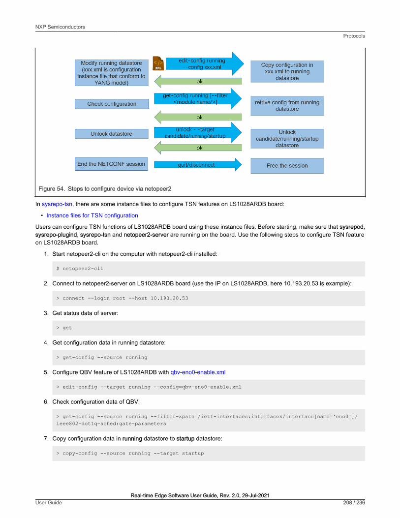
Figure 54. Steps to configure device via netopeer2
In sysrepo-tsn, there are some instance files to configure TSN features on LS1028ARDB board:
• Instance files for TSN configuration
Users can configure TSN functions of LS1028ARDB board using these instance files. Before starting, make sure that sysrepod,sysrepo-plugind, sysrepo-tsn and netopeer2-server are running on the board. Use the following steps to configure TSN featureon LS1028ARDB board.
1. Start netopeer2-cli on the computer with netopeer2-cli installed:
$ netopeer2-cli
2. Connect to netopeer2-server on LS1028ARDB board (use the IP on LS1028ARDB, here 10.193.20.53 is example):
> connect --login root --host 10.193.20.53
3. Get status data of server:
> get
4. Get configuration data in running datastore:
> get-config --source running
5. Configure QBV feature of LS1028ARDB with qbv-eno0-enable.xml
> edit-config --target running --config=qbv-eno0-enable.xml
6. Check configuration data of QBV:
> get-config --source running --filter-xpath /ietf-interfaces:interfaces/interface[name='eno0']/ieee802-dot1q-sched:gate-parameters
7. Copy configuration data in running datastore to startup datastore:
> copy-config --source running --target startup
NXP SemiconductorsProtocols
Real-time Edge Software User Guide, Rev. 2.0, 29-Jul-2021User Guide 208 / 236

8. Disconnect with netopeer2-server:
> disconnect
5.4.3.8 Application scenarios
The related xml file in the following cases can be obtained from the link: https://github.com/real-time-edge-sw/real-time-edge-sysrepo/blob/master/Instances.
NOTE
The interface name in the xml file should match with the actual interface name used on the board.
NOTE
1. Prerequisites:
a. Start netopeer2-cli on the computer with netopeer2-cli installed:
$ netopeer2-cli
b. Connect to the notopeer2-server using the command below:
> connect --login root --host 10.193.20.53
2. Configure the IP address:
a. Edit configuration file, change Ethernet interface name and IP:
$ vim ietf-ip-cfg.xml
b. Send the configuration file:
> edit-config --target running --config=ietf-ip-cfg.xml
3. Configure the MAC address for the bridge:
a. Create a bridge named br1:
$ ip link add name br1 type bridge
b. Edit the configuration file, change bridge name and MAC:
$ vim ietf-mac-cfg.xml
c. Send the configuration file:
$ edit-config --target running --config=ietf-mac-cfg.xml
4. Add VLAN for Ethernet interface:
a. Create bridge named "br1" if not existing:
$ ip link add name br1 type bridge
b. Edit the configuration file to change the interface name and VLAN ID:
$ vim ietf-vlan-cfg.xml
NXP SemiconductorsProtocols
Real-time Edge Software User Guide, Rev. 2.0, 29-Jul-2021User Guide 209 / 236

c. Send the configuration file:
> edit-config --target running --config=ietf-vlan-cfg.xml
5. Configure LS1028ARDB Qbv via tc.
a. Edit the configuration file to change the interface name and VLAN ID:
$ vim qbv-swp0-enable.xml
b. Send the configuration file:
> edit-config --target running --config=qbv-swp0-enable.xml
c. Show the result.
# tc qdisc show dev swp0
If using tc or ethtool commands instead of libtsn, enable "real-time-edge-sysrepo-tc" in conf/distro/include/real-time-edge-base.inc as shown below:
REAL_TIME_EDGE_SYSREPO_ls1028ardb = "real-time-edge-sysrepo-tc"
Otherwise, disable "real-time-edge-sysrepo-tc":
REAL_TIME_EDGE_SYSREPO_ls1028ardb = ""
NOTE
• For LS1028ARDB board, if real-time-edge-sysrepo-tc is enabled, you should set prerequisite for swpx (swp0 swp1or swp2 ...) port using the following commands:
# tc qdisc add dev swpx ingress# tc filter add dev swpx ingress chain 0 pref 49152 flower skip_sw action goto chain 10000# tc filter add dev swpx ingress chain 10000 pref 49152 flower skip_sw # action goto chain 11000# tc filter add dev swpx ingress chain 11000 pref 49152 flower skip_sw action goto chain 12000# tc filter add dev swpx ingress chain 12000 pref 49152 flower skip_sw action goto chain 20000# tc filter add dev swpx ingress chain 20000 pref 49152 flower skip_sw action goto chain 21000# tc filter add dev swpx ingress chain 21000 pref 49152 flower skip_sw action goto chain 30000
6. Configure LS1028ARDB Qci via tc using the steps below.
a. Create a bridge named "switch" if not existing:
# ip link add name switch type bridge
b. Edit and send configuration file:
edit-config --target running --config=switch-qci-fm-gate-enable.xml
c. Show the result.
# tc filter show dev swp0 ingress
NXP SemiconductorsProtocols
Real-time Edge Software User Guide, Rev. 2.0, 29-Jul-2021User Guide 210 / 236

d. Disable the configuration.
> edit-config --target running --config=switch-qci-fm-gate-disable.xml
• The destination-address in instance file should be learned by switch.
• Users should send switch-qci-fm-gate-disable.xml after switch-qci-fm-gate-enable.xml
NOTE
7. Configure LS1028ARDB Qbu via ethtool using the steps below.
a. Edit and send configuration file:
> edit-config --target running --config=qbu-swp0.xml
b. Show the result:
# ethtool --show-frame-preemption swp0
8. Configure LS1028ARDB VLAN ID and priority filter via tc:
a. Edit configuration file, change the interface name and action_spec:
$ vim ietf-br-vlan-cfg.xml
b. Send the configuration file:
> edit-config --target running --config=ietf-br-vlan-cfg.xml
9. Configure SJA1105 Qbv via tc
a. Edit and send configuration file
> edit-config --target running --config=qbv-swp5-tc.xml
b. Show the result:
# tc qdisc show dev swp5
Due to hardware limitation of SJA1105, if you want to config qbv again, you should delete the former qdisc usingthe following command:
NOTE
# tc qdisc del dev swp5 parent root handle 100
10. Configure SJA1105 Qci gate via tc
a. Create bridge named "switch" if not existing:
# ip link add name switch type bridge
b. Edit and send configuration file:
> edit-config --target running --config=switch-qci-gate-swp2-enable.xml
c. Show the result:
# tc filter show dev swp2 ingress
NXP SemiconductorsProtocols
Real-time Edge Software User Guide, Rev. 2.0, 29-Jul-2021User Guide 211 / 236

If you want to test Qci flow meter, you must send switch-qci-fm-swp2-enable.xml.
NOTE
The engine used to schedule the ingress gate operations is the same that the one used for the tc-taprio offload.Therefore, the restrictions regarding the fact that no two gate actions (either tc-gate or tc-taprio gates) may fire atthe same time (during the same 200 ns slot) still apply.
NOTE
11. Configure i.MX 8M Plus Qbv via tc.
a. Edit and send configuration file:
> edit-config --target running --config=qbv-eth1-enable.xml
b. Display the result using the command below:
# tc qdisc show dev eth1
12. Configure i.MX 8M Plus Qbu via ethtool.
a. Edit and send configuration file:
> edit-config --target running --config=qbu-eth1.xml
b. Display the result using the command below:
# ethtool --show-frame-preemption eth1
5.4.4 Troubleshooting1. Connection fails at client side:
nc ERROR: Remote host key changed, the connection will be terminated!nc ERROR: Checking the host key failed.cmd_connect: Connecting to the 10.193.20.4:830 as user "root" failed.
Fixing:
The reason is that the SSHD key changed at the server.
• First, users should get host list using the command knownhosts.
• Then, remove the related item. For example knownhosts --del 19.
2. Request could not be completed because the relevant data model content does not exist.
type: applicationtag: data-missingseverity: errorpath: /ietf-interfaces:interfaces/interface[name='eno0']/ieee802-dot1q-sched:gate-parameters/admin-gate-statesmessage: Request could not be completed because the relevant data model content does not exist.
Fixing:
The reason is that the configuration data in xpath does not exist in the datastore. Such as deleting a node that does not exist.
When encountering such an error, user can get configuration data in the board with get-config command, and checkwhether the operation type (add/delete/modify) of the node in the path is reasonable or not.
NXP SemiconductorsProtocols
Real-time Edge Software User Guide, Rev. 2.0, 29-Jul-2021User Guide 212 / 236

5.5 Graphics on LS1028AThis chaper is applicable to LS1028A. For i.MX 8M Plus and 8M Mini, refer to i.MX Graphics User's Guide for verificationof features.
5.5.1 GPUThe GPU consists of a 3D graphics core and a 2D graphics core.
3D graphics core features are the following:
• Supports 166 million triangles/sec
• Supports 1 Giga pixel/sec fill rate
• Supports 16 GFLOPs
• Supports OpenGL ES 1.1, 2.0, 3.0, 3.1
• Supports OpenCL 1.2
• Vulkan
2D graphics core features are:
• Supports multi-source composition
• Supports one-pass filter
• Supports tile format from 3D graphics core
• Supports tile format from VPU
Step1: Software setting and configuration
GPU is enabled by default when compiling the image for i.MX 8M Plus, i.MX 8M Mini and LS1028A.
Step 2: Hardware setup
• For LS1028ARDB, connect the monitor and LS1028ARDB with DP cable.
• For i.MX 8M Mini EVK, connect MIPI-DSI to HDMI module, then connect to monitor.
• For i.MX 8M Plus EVK, connect the monitor and i.MX 8M Plus EVK with HDMI cable.
Insert the USB mouse into USB port in the keyboard.
Step 3: Running GPU demo
OpenCL demo (example A and B) just suites to LS1028ARDB and i.MX 8M Plus EVK. i.MX 8M Mini EVK does not supportthis feature.
A. OpenCL information
root@LS1028ARDB:~# cd /usr/share/examples/viv_samples/cl11/UnitTestroot@LS1028ARDB-Ubuntu:/usr/share/examples/viv_samples/cl11/UnitTest# ./clinfo
>>>>>>>> ./clinfo Starting...
Available platforms: 1
Platform ID: 0 CL_PLATFORM_NAME: Vivante OpenCL Platform CL_PLATFORM_PROFILE: FULL_PROFILE CL_PLATFORM_VERSION: OpenCL 1.2 V6.4.0.p2.234062 CL_PLATFORM_VENDOR: Vivante Corporation CL_PLATFORM_EXTENSIONS: cl_khr_icd
NXP SemiconductorsProtocols
Real-time Edge Software User Guide, Rev. 2.0, 29-Jul-2021User Guide 213 / 236

Available devices: 1
Device ID: 0 Device Ptr: 0xd04742f0 CL_DEVICE_NAME: Vivante OpenCL Device GC7000UL.6202.0000 CL_DEVICE_VENDOR: Vivante Corporation CL_DEVICE_TYPE: GPU CL_DEVICE_OPENCL_C_VERSION: OpenCL C 1.2 CL_DEVICE_VENDOR_ID: 0x00564956 CL_DEVICE_PLATFORM: 0x9e272728 CL_DEVICE_VERSION: OpenCL 1.2 CL_DEVICE_PROFILE: FULL_PROFILE CL_DRIVER_VERSION: OpenCL 1.2 V6.4.0.p2.234062 CL_DEVICE_MAX_COMPUTE_UNITS: 1 CL_DEVICE_MAX_WORK_ITEM_DIMENSIONS: 3 CL_DEVICE_MAX_WORK_ITEM_SIZES[0]: 512 CL_DEVICE_MAX_WORK_ITEM_SIZES[1]: 512 CL_DEVICE_MAX_WORK_ITEM_SIZES[2]: 512 CL_DEVICE_MAX_WORK_GROUP_SIZE: 512 CL_DEVICE_MAX_CLOCK_FREQUENCY: 650 MHz CL_DEVICE_IMAGE_SUPPORT: Yes CL_DEVICE_MAX_READ_IMAGE_ARGS: 128 CL_DEVICE_MAX_WRITE_IMAGE_ARGS: 8 CL_DEVICE_IMAGE2D_MAX_WIDTH: 8192 CL_DEVICE_IMAGE2D_MAX_HEIGHT: 8192 CL_DEVICE_IMAGE3D_MAX_WIDTH: 8192 CL_DEVICE_IMAGE3D_MAX_HEIGHT: 8192 CL_DEVICE_IMAGE3D_MAX_DEPTH: 8192 CL_DEVICE_MAX_SAMPLERS: 16...
B. Fourier transform based on GPU
root@LS1028ARDB-Ubuntu:~# cd /usr/share/examples/viv_samples/cl11/fft/root@LS1028ARDB-Ubuntu:/usr/share/examples/viv_samples/cl11/fft# ./fft 16Block size: 16Print result: yes
Initializing device(s)...Get the Device info and select Device...# of Devices Available = 1# of Compute Units = 1# compute units = 1Creating Command Queue...log2(fft size) = log2(16)=4Compiling radix-2 FFT Program for GPU...creating radix-2 kernels...Creating kernel fft_radix2 0 (p=1)...Creating kernel fft_radix2 1 (p=2)...Creating kernel fft_radix2 2 (p=4)...Creating kernel fft_radix2 3 (p=8)...Setting kernel args for kernel 0 (p=1)...Setting kernel args for kernel 1 (p=2)...Setting kernel args for kernel 2 (p=4)...Setting kernel args for kernel 3 (p=8)...running kernel 0 (p=1)...running kernel 1 (p=2)...running kernel 2 (p=4)...running kernel 3 (p=8)...Kernel execution time on GPU (kernel 0) : 0.000118 seconds
NXP SemiconductorsProtocols
Real-time Edge Software User Guide, Rev. 2.0, 29-Jul-2021User Guide 214 / 236
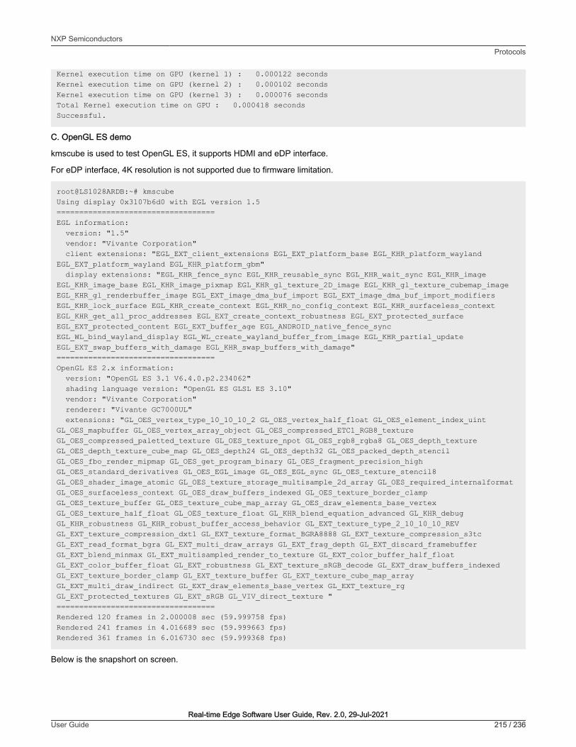
Kernel execution time on GPU (kernel 1) : 0.000122 secondsKernel execution time on GPU (kernel 2) : 0.000102 secondsKernel execution time on GPU (kernel 3) : 0.000076 secondsTotal Kernel execution time on GPU : 0.000418 secondsSuccessful.
C. OpenGL ES demo
kmscube is used to test OpenGL ES, it supports HDMI and eDP interface.
For eDP interface, 4K resolution is not supported due to firmware limitation.
root@LS1028ARDB:~# kmscubeUsing display 0x3107b6d0 with EGL version 1.5===================================EGL information: version: "1.5" vendor: "Vivante Corporation" client extensions: "EGL_EXT_client_extensions EGL_EXT_platform_base EGL_KHR_platform_wayland EGL_EXT_platform_wayland EGL_KHR_platform_gbm" display extensions: "EGL_KHR_fence_sync EGL_KHR_reusable_sync EGL_KHR_wait_sync EGL_KHR_image EGL_KHR_image_base EGL_KHR_image_pixmap EGL_KHR_gl_texture_2D_image EGL_KHR_gl_texture_cubemap_image EGL_KHR_gl_renderbuffer_image EGL_EXT_image_dma_buf_import EGL_EXT_image_dma_buf_import_modifiers EGL_KHR_lock_surface EGL_KHR_create_context EGL_KHR_no_config_context EGL_KHR_surfaceless_context EGL_KHR_get_all_proc_addresses EGL_EXT_create_context_robustness EGL_EXT_protected_surface EGL_EXT_protected_content EGL_EXT_buffer_age EGL_ANDROID_native_fence_sync EGL_WL_bind_wayland_display EGL_WL_create_wayland_buffer_from_image EGL_KHR_partial_update EGL_EXT_swap_buffers_with_damage EGL_KHR_swap_buffers_with_damage"===================================OpenGL ES 2.x information: version: "OpenGL ES 3.1 V6.4.0.p2.234062" shading language version: "OpenGL ES GLSL ES 3.10" vendor: "Vivante Corporation" renderer: "Vivante GC7000UL" extensions: "GL_OES_vertex_type_10_10_10_2 GL_OES_vertex_half_float GL_OES_element_index_uint GL_OES_mapbuffer GL_OES_vertex_array_object GL_OES_compressed_ETC1_RGB8_texture GL_OES_compressed_paletted_texture GL_OES_texture_npot GL_OES_rgb8_rgba8 GL_OES_depth_texture GL_OES_depth_texture_cube_map GL_OES_depth24 GL_OES_depth32 GL_OES_packed_depth_stencil GL_OES_fbo_render_mipmap GL_OES_get_program_binary GL_OES_fragment_precision_high GL_OES_standard_derivatives GL_OES_EGL_image GL_OES_EGL_sync GL_OES_texture_stencil8 GL_OES_shader_image_atomic GL_OES_texture_storage_multisample_2d_array GL_OES_required_internalformat GL_OES_surfaceless_context GL_OES_draw_buffers_indexed GL_OES_texture_border_clamp GL_OES_texture_buffer GL_OES_texture_cube_map_array GL_OES_draw_elements_base_vertex GL_OES_texture_half_float GL_OES_texture_float GL_KHR_blend_equation_advanced GL_KHR_debug GL_KHR_robustness GL_KHR_robust_buffer_access_behavior GL_EXT_texture_type_2_10_10_10_REV GL_EXT_texture_compression_dxt1 GL_EXT_texture_format_BGRA8888 GL_EXT_texture_compression_s3tc GL_EXT_read_format_bgra GL_EXT_multi_draw_arrays GL_EXT_frag_depth GL_EXT_discard_framebuffer GL_EXT_blend_minmax GL_EXT_multisampled_render_to_texture GL_EXT_color_buffer_half_float GL_EXT_color_buffer_float GL_EXT_robustness GL_EXT_texture_sRGB_decode GL_EXT_draw_buffers_indexed GL_EXT_texture_border_clamp GL_EXT_texture_buffer GL_EXT_texture_cube_map_array GL_EXT_multi_draw_indirect GL_EXT_draw_elements_base_vertex GL_EXT_texture_rg GL_EXT_protected_textures GL_EXT_sRGB GL_VIV_direct_texture "===================================Rendered 120 frames in 2.000008 sec (59.999758 fps)Rendered 241 frames in 4.016689 sec (59.999663 fps)Rendered 361 frames in 6.016730 sec (59.999368 fps)
Below is the snapshort on screen.
NXP SemiconductorsProtocols
Real-time Edge Software User Guide, Rev. 2.0, 29-Jul-2021User Guide 215 / 236
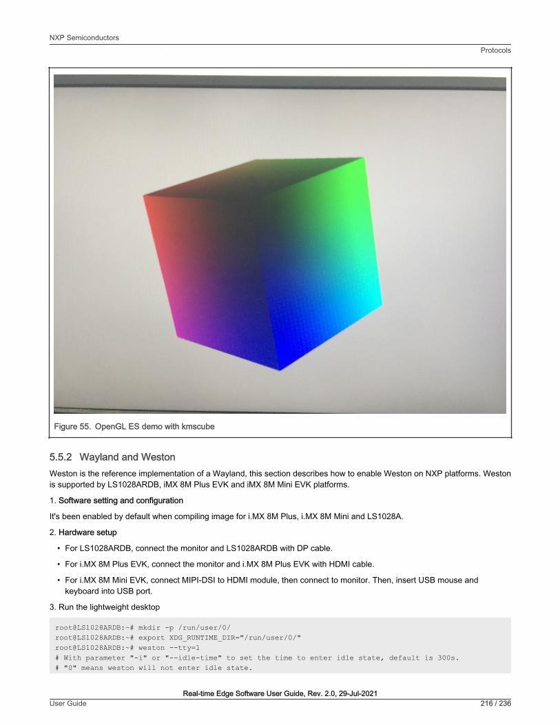
Figure 55. OpenGL ES demo with kmscube
5.5.2 Wayland and WestonWeston is the reference implementation of a Wayland, this section describes how to enable Weston on NXP platforms. Westonis supported by LS1028ARDB, iMX 8M Plus EVK and iMX 8M Mini EVK platforms.
1. Software setting and configuration
It's been enabled by default when compiling image for i.MX 8M Plus, i.MX 8M Mini and LS1028A.
2. Hardware setup
• For LS1028ARDB, connect the monitor and LS1028ARDB with DP cable.
• For i.MX 8M Plus EVK, connect the monitor and i.MX 8M Plus EVK with HDMI cable.
• For i.MX 8M Mini EVK, connect MIPI-DSI to HDMI module, then connect to monitor. Then, insert USB mouse andkeyboard into USB port.
3. Run the lightweight desktop
root@LS1028ARDB:~# mkdir -p /run/user/0/root@LS1028ARDB:~# export XDG_RUNTIME_DIR="/run/user/0/"root@LS1028ARDB:~# weston --tty=1# With parameter "-i" or "--idle-time" to set the time to enter idle state, default is 300s.# "0" means weston will not enter idle state.
NXP SemiconductorsProtocols
Real-time Edge Software User Guide, Rev. 2.0, 29-Jul-2021User Guide 216 / 236

root@LS1028ARDB:~# weston --tty=1 -i 0 # or root@LS1028ARDB:~# weston --tty=1 --idle-time=0
Date: 2020-08-20 UTC[14:38:00.002] weston 8.0.0 https://wayland.freedesktop.org Bug reports to: https://gitlab.freedesktop.org/wayland/weston/issues/ Build: 8.0.0[14:38:00.002] Command line: weston --tty=1[14:38:00.002] OS: Linux, 5.4.3-rt1, #1 SMP PREEMPT_RT Tue Aug 18 14:49:14 CST 2020, aarch64[14:38:00.002] Starting with no config file.[14:38:00.005] Output repaint window is 16 ms maximum.[14:38:00.007] Loading module '/usr/lib/libweston-8/drm-backend.so'[14:38:00.050] initializing drm backend[14:38:00.054] using /dev/dri/card0[14:38:00.054] DRM: supports universal planes[14:38:00.054] DRM: supports atomic modesetting[14:38:00.054] DRM: supports picture aspect ratio[14:38:00.056] Loading module '/usr/lib/libweston-8/gl-renderer.so'[14:38:00.208] EGL client extensions: EGL_EXT_client_extensions EGL_EXT_platform_base EGL_KHR_platform_wayland EGL_EXT_platform_wayland EGL_KHR_platform_gbm[14:38:00.224] EGL version: 1.5[14:38:00.224] EGL vendor: Vivante Corporation[14:38:00.224] EGL client APIs: OpenGL_ES OpenGL OpenVG[14:38:00.224] EGL extensions: EGL_KHR_fence_sync EGL_KHR_reusable_sync EGL_KHR_wait_sync EGL_KHR_image EGL_KHR_image_base EGL_KHR_image_pixmap EGL_KHR_gl_texture_2D_image EGL_KHR_gl_texture_cubemap_image EGL_KHR_gl_renderbuffer_image EGL_EXT_image_dma_buf_import EGL_EXT_image_dma_buf_import_modifiers EGL_KHR_lock_surface EGL_KHR_create_context EGL_KHR_no_config_context EGL_KHR_surfaceless_context EGL_KHR_get_all_proc_addresses EGL_EXT_create_context_robustness EGL_EXT_protected_surface EGL_EXT_protected_content EGL_EXT_buffer_age EGL_ANDROID_native_fence_sync EGL_WL_bind_wayland_display EGL_WL_create_wayland_buffer_from_image EGL_KHR_partial_update EGL_EXT_swap_buffers_with_damage EGL_KHR_swap_buffers_with_damage[14:38:00.224] EGL_KHR_surfaceless_context available[14:38:00.310] GL version: OpenGL ES 3.1 V6.4.0.p2.234062[14:38:00.311] GLSL version: OpenGL ES GLSL ES 3.10[14:38:00.311] GL vendor: Vivante Corporation[14:38:00.311] GL renderer: Vivante GC7000UL[14:38:00.311] GL extensions: GL_OES_vertex_type_10_10_10_2 GL_OES_vertex_half_float GL_OES_element_index_uint GL_OES_mapbuffer GL_OES_vertex_array_object GL_OES_compressed_ETC1_RGB8_texture GL_OES_compressed_paletted_texture GL_OES_texture_npot GL_OES_rgb8_rgba8 GL_OES_depth_texture GL_OES_depth_texture_cube_map GL_OES_depth24 GL_OES_depth32 GL_OES_packed_depth_stencil GL_OES_fbo_render_mipmap GL_OES_get_program_binary GL_OES_fragment_precision_high GL_OES_standard_derivatives GL_OES_EGL_image GL_OES_EGL_sync GL_OES_texture_stencil8 GL_OES_shader_image_atomic GL_OES_texture_storage_multisample_2d_array GL_OES_required_internalformat GL_OES_surfaceless_context GL_OES_draw_buffers_indexed GL_OES_texture_border_clamp GL_OES_texture_buffer GL_OES_texture_cube_map_array GL_OES_draw_elements_base_vertex GL_OES_texture_half_float
NXP SemiconductorsProtocols
Real-time Edge Software User Guide, Rev. 2.0, 29-Jul-2021User Guide 217 / 236

GL_OES_texture_float GL_KHR_blend_equation_advanced GL_KHR_debug GL_KHR_robustness GL_KHR_robust_buffer_access_behavior GL_EXT_texture_type_2_10_10_10_REV GL_EXT_texture_compression_dxt1 GL_EXT_texture_format_BGRA8888 GL_EXT_texture_compression_s3tc GL_EXT_read_format_bgra GL_EXT_multi_draw_arrays GL_EXT_frag_depth GL_EXT_discard_framebuffer GL_EXT_blend_minmax GL_EXT_multisampled_render_to_texture GL_EXT_color_buffer_half_float GL_EXT_color_buffer_float GL_EXT_robustness GL_EXT_texture_sRGB_decode GL_EXT_draw_buffers_indexed GL_EXT_texture_border_clamp GL_EXT_texture_buffer GL_EXT_texture_cube_map_array GL_EXT_multi_draw_indirect GL_EXT_draw_elements_base_vertex GL_EXT_texture_rg GL_EXT_protected_textures GL_EXT_sRGB GL_VIV_direct_texture[14:38:00.311] GL ES 2 renderer features: read-back format: BGRA wl_shm sub-image to texture: yes EGL Wayland extension: yes[14:38:00.343] warning: no input devices on entering Weston. Possible causes: - no permissions to read /dev/input/event* - seats misconfigured (Weston backend option 'seat', udev device property ID_SEAT)[14:38:00.343] failed to create input devices[14:38:00.349] DRM: head 'DP-1' found, connector 56 is connected, EDID make 'DEL', model 'DELL P2417H', serial 'C9G5D7561ECB'[14:38:00.349] Registered plugin API 'weston_drm_output_api_v1' of size 24[14:38:00.357] Chosen EGL config details: id: 41 rgba: 8 8 8 0 buf: 24 dep: 0 stcl: 0 int: 1-60 type: win|pix|pbf|swap_preserved vis_id: XRGB8888 (0x34325258)[14:38:00.357] Output DP-1 (crtc 48) video modes: [email protected], preferred, current, 148.5 MHz [email protected], 108.0 MHz [email protected], 135.0 MHz [email protected], 108.0 MHz [email protected], 108.0 MHz [email protected], 78.8 MHz [email protected], 65.0 MHz [email protected], 49.5 MHz [email protected], 40.0 MHz [email protected], 31.5 MHz [email protected], 25.2 MHz [email protected], 28.3 MHz[14:38:00.357] Output 'DP-1' enabled with head(s) DP-1[14:38:00.357] Compositor capabilities: arbitrary surface rotation: yes screen capture uses y-flip: yes presentation clock: CLOCK_MONOTONIC, id 1 presentation clock resolution: 0.000000001 s[14:38:00.359] Loading module '/usr/lib/weston/desktop-shell.so'[14:38:00.367] launching '/usr/libexec/weston-keyboard'[14:38:00.373] launching '/usr/libexec/weston-desktop-shell'[14:39:23.341] event0 - Logitech USB Optical Mouse: is tagged by udev as: Mouse[14:39:23.341] event0 - Logitech USB Optical Mouse: device is a pointer[14:39:23.341] libinput: configuring device "Logitech USB Optical Mouse".[14:39:23.342] associating input device event0 with output DP-1 (none by udev)could not load cursor 'dnd-move'could not load cursor 'dnd-copy'could not load cursor 'dnd-none'[14:39:33.459] event0 - Logitech USB Optical Mouse: device removed[14:39:51.794] event0 - Dell Dell USB Keyboard: is tagged by udev as: Keyboard
NXP SemiconductorsProtocols
Real-time Edge Software User Guide, Rev. 2.0, 29-Jul-2021User Guide 218 / 236

[14:39:51.794] event0 - Dell Dell USB Keyboard: device is a keyboard[14:39:51.859] libinput: configuring device "Dell Dell USB Keyboard".[14:39:51.859] associating input device event0 with output DP-1 (none by udev)[14:40:03.937] event0 - Dell Dell USB Keyboard: device removed[14:40:11.758] event0 - Logitech USB Optical Mouse: is tagged by udev as: Mouse[14:40:11.758] event0 - Logitech USB Optical Mouse: device is a pointer[14:40:11.758] libinput: configuring device "Logitech USB Optical Mouse".[14:40:11.758] associating input device event0 with output DP-1 (none by udev)[14:40:19.403] event0 - Logitech USB Optical Mouse: device removed[14:40:29.454] event0 - Dell Dell USB Keyboard: is tagged by udev as: Keyboard[14:40:29.454] event0 - Dell Dell USB Keyboard: device is a keyboard[14:40:29.454] libinput: configuring device "Dell Dell USB Keyboard".[14:40:29.454] associating input device event0 with output DP-1 (none by udev)[14:41:00.156] event0 - Dell Dell USB Keyboard: device removed
[14:42:29.287] event0 - Logitech USB Optical Mouse: is tagged by udev as: Mouse[14:42:29.287] event0 - Logitech USB Optical Mouse: device is a pointer[14:42:29.287] libinput: configuring device "Logitech USB Optical Mouse".[14:42:29.287] associating input device event0 with output DP-1 (none by udev)[14:42:35.418] event1 - Dell Dell USB Keyboard: is tagged by udev as: Keyboard[14:42:35.419] event1 - Dell Dell USB Keyboard: device is a keyboard[14:42:35.419] libinput: configuring device "Dell Dell USB Keyboard".[14:42:35.419] associating input device event1 with output DP-1 (none by udev)
Below is the snapshot.
NXP SemiconductorsProtocols
Real-time Edge Software User Guide, Rev. 2.0, 29-Jul-2021User Guide 219 / 236

Figure 56. Weston demo
5.5.3 CSI CameraNXP provides i.MX 8M Mini EVK board that have CSI MIPI and DSI MIPI interfaces. The gstreamer video stream captures videoframe from CSI camera and displays it to screen via DSI MIPI interface. The element waylandsink is based on wayland libraryand Weston desktop. Refer to Wayland and Weston to enable them. Users should follow the steps below to enable gstreameron a target board.
1. Software setting and configuration
Gstream is enabled by default.
2. Hardware setup
• For i.MX 8M Mini EVK boards, DSI MIPI and CSI MIPI modules are connected to the board.
• MIPI-DSI to HDMI interface:
NXP SemiconductorsProtocols
Real-time Edge Software User Guide, Rev. 2.0, 29-Jul-2021User Guide 220 / 236

Figure 57. MIPI-DSI to HDMI interface
3. MIPI-CSI camera module: The following figure shows the MIPI-CSI camera module:
Figure 58. MIPI-CSI camera module
4. Run gstreamer for camera.
After entering Linux prompt, run gstreamer command as shown in the below steps:
[root@imx8mmevk ~] # gst-launch-1.0 v4l2src device= /dev/video0 ! 'video/x-raw,width=640,height=480,framerate=(fraction)30/1' ! videoconvert ! fbdevsink
Below is the snapshot with fbdevsink:
NXP SemiconductorsProtocols
Real-time Edge Software User Guide, Rev. 2.0, 29-Jul-2021User Guide 221 / 236

Figure 59. fbdevsink
5. Run wayland and weston for waylandsink using the commands shown below:
[root@imx8mmevk ~] # mkdir -p /run/user/0/[root@imx8mmevk ~] # export XDG_RUNTIME_DIR="/run/user/0/"[root@imx8mmevk ~] # weston --tty=1 &[root@imx8mmevk ~] # gst-launch-1.0 v4l2src device= /dev/video0 ! 'video/x-raw,width=640,height=480,framerate=(fraction)30/1' ! videoconvert ! waylandsink
The below snapshot shows waylandsink implementation:
NXP SemiconductorsProtocols
Real-time Edge Software User Guide, Rev. 2.0, 29-Jul-2021User Guide 222 / 236

Figure 60. Waylandsink implementation
5.6 Wireless on LS1028A
5.6.1 NFCNFC click board is a mikroBUS™ add-on board with a versatile near field communications controller from NXP — the PN7120IC. NFC devices are used in contactless payment systems, electronic ticketing, smartcards. In retail and advertising, inexpensiveNFC tags can be embedded into packaging labels, flyers, or posters.
This board is fully compliant with NFC Forum specifications. This implies that users can use the full potential of NFC and its threedistinct operating modes listed below:
1. Card emulation
2. Read/Write
3. P2P
5.6.1.1 Introduction
The NXP’s PN7120 IC integrates an Arm™ Cortex-M0 MCU, which enables easier integration into designs, because it requiresfewer resources from the host MCU. The integrated firmware provides all NFC protocols for performing the contactlesscommunication in charge of the modulation, data processing, and error detection.
The board communicates with the target board MCU through the mikroBUS™ I2C interface, in compliance with NCI (NFCcontroller interface) 1.0 host protocols. RST and INT pins provide additional functionality. The board uses a 3.3 V power supply.
NXP SemiconductorsProtocols
Real-time Edge Software User Guide, Rev. 2.0, 29-Jul-2021User Guide 223 / 236

5.6.1.2 PN7120 features
PN7120 IC embeds a new generation RF contactless front-end, supporting various transmission modes according to NFCIP-1 andNFCIP-2, ISO/IEC14443, ISO/IEC 15693, ISO/IEC 18000-3, MIFARE, and FeliCa specifications. It embeds an Arm Cortex-M0microcontroller core loaded with the integrated firmware supporting the NCI 1.0 host communication.
5.6.1.3 Hardware preparation
Use the following hardware items for the NFC clickboard demo setup:
1. LS1028ARDB
2. NFC click board
3. NFC sample card (tag)
Users should insert the NFC click board into the LS1028ARDB mikroBUS1 slot.
NOTE
5.6.1.4 Software preparation
In order to support NFC click board, use the following steps:
1. In Real-time Edge, libnfc-nci is enabled by default.
2. In Linux kernel configuration, make sure the below options are enabled:
[*] Networking support ---> <M> NFC subsystem support ---> Near Field Communication (NFC) devices ---> <M> NXP PN5XX based driver
The NXP PN5XX based driver only supports the Module mode.
NOTE
3. Use the make command to create the images.
5.6.1.5 Testing the NFC click board
Use the following steps for testing the NFC Clickboard:
1. Install NFC driver module
[root]# modprobe pn5xx_i2c.ko
2. The following log appears at the console after the above command is successful. The error information can be ignored inthis case.
NXP SemiconductorsProtocols
Real-time Edge Software User Guide, Rev. 2.0, 29-Jul-2021User Guide 224 / 236

3. Run the nfcDemoApp application:
[root]# nfcDemoApp poll
4. Put the NFC Sample Card (tag) on top of the NFC click board:
Display of the above information indicates successful card reading.
5.6.2 Bluetooth Low EnergyThis chapter introduces the features of the Bluetooth Low Energy P click board and how to use it on NXP's LS1028A referencedesign board (RDB).
5.6.2.1 Introduction
Bluetooth Low Energy P click carries the nRF8001 IC that allows user to add Bluetooth 4.0 to user's device. The clickcommunicates with the target board MCU through mikroBUS™ SPI (CS, SCK, MISO, MOSI), RDY and ACT lines, and runs on3.3 V power supply.
Bluetooth Low Energy P click features a PCB trace antenna, designed for the 2400 MHz to 2483.5 MHz frequency band. Themaximum device range is up to 40 meters in open space.
NXP SemiconductorsProtocols
Real-time Edge Software User Guide, Rev. 2.0, 29-Jul-2021User Guide 225 / 236

5.6.2.2 Bluetooth Low Energy
LS1028ARDB support Bluetooth Low Energy click board, Bluetooth Low Energy P click carries the nRF8001 IC that allows userto add Bluetooth 4.0 to the device.
5.6.2.3 Features
Following are the features provided by BLE P clickboard:
• nRF8001 Bluetooth low energy RF transceiver
— 16 MHz crystal oscillator
— Ultra-low peak current consumption <14 mA
— Low current for connection-oriented profiles, typically 2 μA
• PCB trace antenna (2400-2483.5 MHz, up to 40 meters)
• BLE Android app
• Interface: SPI (CS, SCK, MISO, MOSI), RDY, and ACT lines
• 3.3 V power supply
5.6.2.4 Hardware preparation
Use the following hardware items for the BLE P click board demo setup:
1. LS1028ARDB
2. BLE P Click board
3. Android phone (option)
The figure below depicts the hardware setup required for the demo:
NXP SemiconductorsProtocols
Real-time Edge Software User Guide, Rev. 2.0, 29-Jul-2021User Guide 226 / 236

Figure 61. BLE P click board hardware setup
5.6.2.5 Software preparation
Use these steps for the BLE P click board demo software setup:
• Download the JUMA UART (Android app) by using the link: https://apkpure.com/juma-uart/com.juma.UART
• Then, run the steps below in order to support BLE P click board:
1. In Real-time Edge, libblep is enabled by default.
2. In Linux kernel configuration, make sure the below options are enabled:
Device Drivers ---> SPI support ---> <*> Freescale DSPI controller <*> User mode SPI device driver support
NXP SemiconductorsProtocols
Real-time Edge Software User Guide, Rev. 2.0, 29-Jul-2021User Guide 227 / 236

3. Use the make command to create the images.
5.6.2.6 Testing the BLE P click board
Use the following steps for testing the BLE P click board:
1. Running the blep_demo application.
The following log is displayed to indicate that the BLE P click board is initialized. After this, users can scan from their mobilephone or computer's Bluetooth device for the BLE P click board. The name of the BLE P click board used is “MikroE”.
2. Connection log
Connect the BLE P click board via mobile app. On successful connection, the following log is displayed. Thereafter, theapplication can communicate with the BLE P click board.
3. Disconnection log
Click the Disconnect button of the Android APP to disconnect from the BLE P click board. The following log displays thatthe disconnection is successful:
4. Command line introduction
NXP SemiconductorsProtocols
Real-time Edge Software User Guide, Rev. 2.0, 29-Jul-2021User Guide 228 / 236

The blep _demo application supports four command lines: devaddr, name=, version, and echo.
a. devaddr
This command is used to obtain the MAC address of the BLE P click board. User can run this command at any time.
b. name=
This command is used to set the Bluetooth name of the BLE P click board while broadcasting. No spaces are requiredafter the equal sign "=", and the content after the 'equal to' sign is the set name. The maximum length is 16 characters.
c. version
This command is used to obtain the version of the BLE P click board. User can run this command at any time.
d. echo
This command is used to send a string to the Android app. This command should be executed after the connectionis established. The maximum length is 20 characters.
The below log displays the message displayed after user tries to send a string when no connection is established:
The below log is displayed when user sends a string after a connection is established:
NXP SemiconductorsProtocols
Real-time Edge Software User Guide, Rev. 2.0, 29-Jul-2021User Guide 229 / 236

5. Receiving data
When the Android app sends a string:
5.6.3 BEEThis chapter introduces the features of the BEE Click Board and how to use it on LS1028ARDB.
5.6.3.1 BEE/ZigBEE
LS1028ARDB supports BEE click board, which can implement the MRF24J40MA 2.4 GHz IEEE 802.15.4 radio transceivermodule from Microchip.
5.6.3.2 Introduction
The BEE Click Board features the MRF24J40MA 2.4 GHz IEEE 802.15.4 radio transceiver module from Microchip. The click isdesigned to run on 3.3 V power supply only. It communicates with the target controller over an SPI interface.
5.6.3.3 Features
The features of the BEE Click Board are listed below:
• PCB antenna
• MRF24J40MA module
• Low current consumption (TX 23 mA, RX 19 mA, Sleep 2 μA)
• ZigBee stack
• MiWi™ stack
• SPI Interface
• 3.3 V power supply
5.6.3.4 Hardware preparation
Use the following hardware items for the BEE Click Board demo setup:
• Two LS1028ARDB Boards
• Two BEE Click Boards
The figure below describes the hardware setup for the BEE Click Board.
NXP SemiconductorsProtocols
Real-time Edge Software User Guide, Rev. 2.0, 29-Jul-2021User Guide 230 / 236

Figure 62. BEE Click Board hardware setup
The WA pin of BEE Click Board connects with the NC pin.
NOTE
5.6.3.5 Software preparation
In order to support BEE click board, use the following steps:
1. In Real-time Edge, libbee is enabled by default.
2. In Linux kernel configuration, make sure the below options are enabled:
Device Drivers ---> SPI support ---> <*> Freescale DSPI controller <*> User mode SPI device driver support -*- GPIO Support ---> [*] /sys/class/gpio/... (sysfs interface) Memory mapped GPIO drivers ---> [*] MPC512x/MPC8xxx/QorIQ GPIO support
3. Use the make command to create the images.
NXP SemiconductorsProtocols
Real-time Edge Software User Guide, Rev. 2.0, 29-Jul-2021User Guide 231 / 236

5.6.3.6 Testing the BEE click board
The test application bee_demo is created by using the BEE Click Board library. This application can transfer the file between twoBEE Click Boards.
1. Users should create a file in any path. For example, ./samples/test.txt.
2. First, start a server node by running the command below:
bee_demo -s -f=XXX
The command parameters are as below:
• -s: This device node acts as a server.
• -f=XXX: This parameter is valid only on the server node. XXX is the file path (relative or absolute) to be transferred.
[root]# lssamples[root]# bee_demo -s -f=./samples/test.txtspi mode: 0x0bits per word: 8max speed: 500000 Hz (500 KHz)BEE Click Board Demo.This node is a server node.Waiting for a clientReading the content of the file
3. Start a client node on another LS1028ARDB by running the command bee_demo -c. In the above command, the parameter-c implies that this device node acts as a client. After receiving the file, the client node automatically exits. The received fileis saved in the current path.
[root]# lssamples[root]# bee_demo -c spi mode: 0x0 bits per word: 8 max speed: 500000 Hz (500 KHz) BEE Click Board Demo. This node is a client node. Starting to get a file Send the SEQ_REQ command. Send the SEQ_START command. Send the SEQ_START command.[root]# lssamples test.txt[root]#
4. The following log indicates that the server node has finished sending a file.
Send the SEQ_INFO command.Start to send the fileIt's completed to send a file.
NXP SemiconductorsProtocols
Real-time Edge Software User Guide, Rev. 2.0, 29-Jul-2021User Guide 232 / 236

Chapter 6Revision historyThe table below summarizes revisions to this document.
Table 62. Document revision history
Date Documentversion
Topic cross-reference Change description
29/07/2021 2.0 - • 'Real-time Edge Processing Software' introduced instead of'Open Industrial Linux', with real-time feature support.
• Rearranged the document structure to include the Chapters:Real-time System, Real-time Networking, and Protocols.
- Added support for building Real-time Edge image using YoctoProject build environment. Details are provided in the Real-timeEdge Yocto Project User Guide.
What's new Added the section.
- Integrated BareMetal framework in the document.
26/04/2021 1.11 What's new Added the section that describes the new features of each release.
- Updated the section 'Getting Open IL'.
- Deleted references to Edgescale, OP-TEE, OTA throughout thedocument and other minor updates.
22/12/2020 1.10 GenAVB/TSN stack Added the chapter and related contents.
- Added the 'Camera' section and related details.
- Added the Host setup for i.MX 8M Plus EVK board details.
15/09/2020 1.9 IEEE 1588/802.1AS Added the section.
GPU Added the chapter and related description.
Wayland and Weston Added the chapter and related description..
real-time-edge-servostack
Made it a part of the chapter "EtherCAT".
29/05/2020 1.8 Preempt-RT Linux Added the section in Protocols.
- Updated this section Interface naming in Linux for LS1028ARDB.
- Updated the section Host system requirements for Open IL.
- Updated the section Running Selinux demo.
20/02/20 1.7.1 Operation examples Updated this section.
17/01/20 1.7 real-time-edge-servostack
Added the chapter (nxp servo).
IEEE 1588/802.1AS Added the chapter
Getting Open IL Updated the section.
Table continues on the next page...
NXP Semiconductors
Real-time Edge Software User Guide, Rev. 2.0, 29-Jul-2021User Guide 233 / 236

Table 62. Document revision history (continued)
Date Documentversion
Topic cross-reference Change description
NETCONF/YANG Other updates.
31/08/19 1.6 TSN on LS1028A • Information related to pcpmap command removed from thesection TSN configuration on ENETC and TSN configuration onFelix switch.
• Port names "eno/swp0" changed to "swp0" for few tsntoolcommands.
• Note added in section Stream identification for usage ofnulltagged and streamhandle parameters.
• Added the section TSN stream identification.
• Other minor updates.
- Updated the table "Host system mandatory packages". Addedautogen autoconf libtool and pkg-config packages.
BEE Added this Chapter.
- Updated NETCONF/YANG.
NETCONF/YANG • Added the section Enabling NETCONF feature and otherupdates.
01/05/2019 1.5 - Added the section to describe interface naming for U-Boot and Linuxfor LS1028ARDB.
TSN on LS1028A Updated this section in the Chapter Time Sensitive Networking(TSN) on NXP platforms.
Bluetooth Low Energy Added the Chapter.
- Added the Chapter 'EdgeScale Client'.
- Updated the OpenIL version and Git tag in the section 'Getting OpenIL'.
01/02/2019 1.4 Supported NXPplatforms
Added support for LS1028ARDB (64-bit and Ubuntu). Updatedvarious sections accordingly.
- Updated the OpenIL version and Git tag in the section 'Getting OpenIL'.
- Added this Section for LS1028ARDB support.
Time SensitiveNetworking (TSN) onNXP platforms
Reorganized this Chapter and added separate Section for TSN onLS1028A.
NFC Added the Chapter.
FlexCAN and CAN Open Minor updates in this Chapter. Also added the section, Hardwarepreparation for LS1028ARDB and Testing CAN bus.
- Added the Chapter QT.
Table continues on the next page...
NXP SemiconductorsRevision history
Real-time Edge Software User Guide, Rev. 2.0, 29-Jul-2021User Guide 234 / 236

Table 62. Document revision history (continued)
Date Documentversion
Topic cross-reference Change description
15/10/2018 1.3.1 - Updated the OpenIL version and Git tag in the section 'Getting OpenIL'.
31/08/2018 1.3 EtherCAT Added the chapter.
FlexCAN Added the chapter.
i.MX6QSabreSDsupport.
Added the section in chapter NXP OpenIL platforms. Updated othersections for i.MX6Q Sabre support.
Getting Open IL Updated the section.
Selinux demo Added the section, #unique_362 and updated Basic setup. Updatesin other sections.
31/05/2018 1.2 - Updated the Section, "Hardware requirements" for RTnet.
- Updated the Section, "Software requirements" for RTnet.
18/04/2018 1.1.1 - Added the Section, "RTnet".
- Added a note for LS1043A switch setting.
30/03/2018 1.1 - Added support for industrial IoT BareMetal framework in this section.
- Added a note for steps to be performed before booting up the board.
Related documentation Added the section.
22/12/2017 1.0 OPC UA Added the Chapter.
Time SensitiveNetworking (TSN) onNXP platforms
Chapters for "1-board TSN demo" and "3-board TSN demo"replaced by a single chapter, "TSN demo".
Protocols • Updated the section, 'Industrial Features'.
• -IEEE 1588 -'sja1105-ptp' support removed.
25/08/2017 0.3 - Set up the OpenIL websitehttp://www.openil.org/.
- OTA - Xenomai Cobalt 64-bit and SJA1105 support added.
Time SensitiveNetworking (TSN) onNXP platforms
Qbv support added.
- SELinux support for LS1043 / LS1046 Ubuntu Userland added.
- OP-TEE support for LS1021ATSN platform added.
- 4G LTE module - 64-bit support for LS1043ARDB, LS1046ARDB,and LS1012ARDB added.
Real-time Networking Ubuntu Userland support for 64-bit LS1043ARDB and 64-bitLS1046ARDB added.
26/05/2017 0.2 - Initial public release.
NXP SemiconductorsRevision history
Real-time Edge Software User Guide, Rev. 2.0, 29-Jul-2021User Guide 235 / 236

How To ReachUs
Home Page:
nxp.com
Web Support:
nxp.com/support
Limited warranty and liability — Information in this document is provided solely to enable system and software implementers to use NXPproducts. There are no express or implied copyright licenses granted hereunder to design or fabricate any integrated circuits based onthe information in this document. NXP reserves the right to make changes without further notice to any products herein.
NXP makes no warranty, representation, or guarantee regarding the suitability of its products for any particular purpose, nor doesNXP assume any liability arising out of the application or use of any product or circuit, and specifically disclaims any and all liability,including without limitation consequential or incidental damages. “Typical” parameters that may be provided in NXP data sheets and/orspecifications can and do vary in different applications, and actual performance may vary over time. All operating parameters, including“typicals,” must be validated for each customer application by customer's technical experts. NXP does not convey any license under itspatent rights nor the rights of others. NXP sells products pursuant to standard terms and conditions of sale, which can be found at thefollowing address: nxp.com/SalesTermsandConditions.
Right to make changes - NXP Semiconductors reserves the right to make changes to information published in this document, includingwithout limitation specifications and product descriptions, at any time and without notice. This document supersedes and replaces allinformation supplied prior to the publication hereof.
Security — Customer understands that all NXP products may be subject to unidentified or documented vulnerabilities. Customeris responsible for the design and operation of its applications and products throughout their lifecycles to reduce the effect of thesevulnerabilities on customer’s applications and products. Customer’s responsibility also extends to other open and/or proprietarytechnologies supported by NXP products for use in customer’s applications. NXP accepts no liability for any vulnerability. Customershould regularly check security updates from NXP and follow up appropriately. Customer shall select products with security features thatbest meet rules, regulations, and standards of the intended application and make the ultimate design decisions regarding its productsand is solely responsible for compliance with all legal, regulatory, and security related requirements concerning its products, regardlessof any information or support that may be provided by NXP. NXP has a Product Security Incident Response Team (PSIRT) (reachableat [email protected]) that manages the investigation, reporting, and solution release to security vulnerabilities of NXP products.
NXP, the NXP logo, NXP SECURE CONNECTIONS FOR A SMARTER WORLD, COOLFLUX,EMBRACE, GREENCHIP, HITAG,ICODE, JCOP, LIFE, VIBES, MIFARE, MIFARE CLASSIC, MIFARE DESFire, MIFARE PLUS, MIFARE FLEX, MANTIS, MIFAREULTRALIGHT, MIFARE4MOBILE, MIGLO, NTAG, ROADLINK, SMARTLX, SMARTMX, STARPLUG, TOPFET, TRENCHMOS,UCODE, Freescale, the Freescale logo, AltiVec, CodeWarrior, ColdFire, ColdFire+, the Energy Efficient Solutions logo, Kinetis,Layerscape, MagniV, mobileGT, PEG, PowerQUICC, Processor Expert, QorIQ, QorIQ Qonverge, SafeAssure, the SafeAssure logo,StarCore, Symphony, VortiQa, Vybrid, Airfast, BeeKit, BeeStack, CoreNet, Flexis, MXC, Platform in a Package, QUICC Engine, Tower,TurboLink, EdgeScale, EdgeLock, eIQ, and Immersive3D are trademarks of NXP B.V. All other product or service names are theproperty of their respective owners. AMBA, Arm, Arm7, Arm7TDMI, Arm9, Arm11, Artisan, big.LITTLE, Cordio, CoreLink, CoreSight,Cortex, DesignStart, DynamIQ, Jazelle, Keil, Mali, Mbed, Mbed Enabled, NEON, POP, RealView, SecurCore, Socrates, Thumb,TrustZone, ULINK, ULINK2, ULINK-ME, ULINK-PLUS, ULINKpro, µVision, Versatile are trademarks or registered trademarks of ArmLimited (or its subsidiaries) in the US and/or elsewhere. The related technology may be protected by any or all of patents, copyrights,designs and trade secrets. All rights reserved. Oracle and Java are registered trademarks of Oracle and/or its affiliates. The PowerArchitecture and Power.org word marks and the Power and Power.org logos and related marks are trademarks and service markslicensed by Power.org. M, M Mobileye and other Mobileye trademarks or logos appearing herein are trademarks of Mobileye VisionTechnologies Ltd. in the United States, the EU and/or other jurisdictions.
© NXP B.V. 2021. All rights reserved.
For more information, please visit: http://www.nxp.comFor sales office addresses, please send an email to: [email protected]
Date of release: 29-Jul-2021Document identifier: REALTIMEEDGEUG