real-time dual-wavelength digital holographic microscopy with a
TRANSCRIPT

Real-time dual-wavelength digitalholographic microscopy with a single
hologram acquisition
Jonas Kuhna, Tristan Colombb, Frederic Montfortc, FlorianCharrierea, Yves Emeryc, Etienne Cuchec, Pierre Marquetb and
Christian Depeursingea
aEcole polytechnique federale de Lausanne,Institute of imaging and applied optics,
CH-1015 Lausanne, Switzerland
http://apl.epfl.ch/page12232.html
bCentre de Neurosciences Psychiatriques, Departement de psychiatrie DP-CHUV, Site deCery, 1008 Prilly-Lausanne, Switzerland
cLyncee Tec SA,PSE-A,
CH-1015 Lausanne, Switzerland
http://www.lynceetec.com
Abstract: A technique to perform two-wavelengths digital holographicmicroscopy (DHM) measurements with a single hologram acquisition ispresented. The vertical measurement range without phase ambiguity isextended to the micron-range, thanks to the resulting synthetic wavelengthdefined by the beating of two wavelengths with a separation of about80nm. Real-time dual-wavelength imaging is made possible by using tworeference waves having different wavelengths and propagation directionsfor the hologram recording. The principle of the method is exposed andexperimental results concerning a 1.2μm m high test sample as well as amoving micro-mirror are presented. To the extent of our knowledge, thisis the first time that real-time synthetic beat-wavelength digital holographymeasurements are reported.
© 2007 Optical Society of America
OCIS codes: (090.1760) Computer holography; (090.4220) Multiplex holography; (120.5050)Phase measurement; (180.3170 Interference microscopy)
References and links1. J. W. Goodman and R. W. Lawrence, “Digital image formation from electronically detected holograms,” Appl.
Phys. Lett. 11, 77–79 (1967).2. U. Schnars and W. Juptner, “Direct recording of holograms by a ccd target and numerical reconstruction,” Appl.
Opt. 33, 179–181 (1994).3. E. Cuche, F. Bevilacqua, and C. Depeursinge, “Digital holography for quantitative phase-contrast imaging,” Opt.
Lett. 24, 291–293 (1999).4. D. Gabor, “A new microscopic principle,” Nature 161, 777–778 (1948).
#81874 - $15.00 USD Received 6 Apr 2007; revised 16 May 2007; accepted 22 May 2007; published 29 May 2007
(C) 2007 OSA 11 June 2007 / Vol. 15, No. 12 / OPTICS EXPRESS 7231

5. E. Cuche, P. Marquet, and C. Depeursinge, “Simultaneous amplitude-contrast and quantitative phase-contrastmicroscopy by numerical reconstruction of fresnel off-axis holograms,” Appl. Opt. 38, 6994–7001 (1999).
6. A. T. Forrester, W. E. Parkins, and E. Gerjuoy, “On the possibility of observing beat frequencies between lines inthe visible spectrum,” Phys. Rev. 72, 728–728 (1947).
7. C. Polhemus, “Two-wavelength interferometry,” Appl. Opt. 12, 2071–2074 (1973).8. F. Bien, M. Camac, H. J. Caulfield, and S. Ezekiel, “Absolute distance measurements by variable wavelength
interferometry,” Appl. Opt. 20, 400–402 (1981).9. R. Dandliker, R. Thalmann, and D. Prongue, “Two-wavelength laser interferometry using superheterodyne de-
tection,” Opt. Lett. 13, 339–341 (1988).10. B. P. Hildebrand and K. A. Haines, “Multiple-wavelength and multiple-source holography applied to contour
generation,” J. Opt. Soc. Am. 57, 155–162 (1967).11. J. S. Zelenka and J. R. Varner, “A new method for generating depth contours holographically,” Appl. Opt. 7,
2107–2110 (1968).12. J. C. Wyant, “Testing aspherics using two-wavelength holography,” Appl. Opt. 10, 2113–2118 (1971).13. C. Wagner, W. Osten, and S. Seebacher, “Direct shape measurement by digital wavefront reconstruction and
multiwavelength contouring,” Opt. Eng. 39, 79–85 (2000).14. J. Gass, A. Dakoff, and M. K. Kim, “Phase imaging without 2 pi ambiguity by multiwavelength digital hologra-
phy,” Opt. Lett. 28, 1141–1143 (2003).15. D. Parshall and M. Kim, “Digital holographic microscopy with dual wavelength phase unwrapping,” Appl. Opt.
45, 451–459 (2006).16. T. Colomb, F. Montfort, J. Kuhn, N. Aspert, E. Cuche, A. Marian, F. Charriere, S. Bourquin, P. Marquet, and
C. Depeursinge, “Numerical parametric lens for shifting, magnification and complete aberration compensationin digital holographic microscopy,” J. Opt. Soc. Am. A 23, 3177–3190 (2006).
17. S. de Nicola, A. Finizio, G. Pierattini, D. Alfieri, S. Grilli, L. Sansone, and P. Ferraro, “Recovering correct phaseinformation in multiwavelength digital holographic microscopy by compensation for chromatic aberrations,”Opt. Lett. 30, 2706–2708 (2005).
18. I. Yamaguchi, K. Yamamoto, G. A. Mills, and M. Yokota, “Image reconstruction only by phase data in phase-shifting digital holography,” Appl. Opt. 45, 975–983 (2006).
19. R. J. Mahon, J. A. Murphy, and W. Lanigan, “Digital holography at millimetre wavelengths,” Opt. Commun.260, 469–473 (2006).
20. F. Zhang, G. Pedrini, and W. Osten, “Reconstruction algorithm for high-numerical-aperture holograms withdiffraction-limited resolution,” Opt. Lett. 31, 1633–1635 (2006).
21. R. Onodera and Y. Ishii, “Two-wavelength interferometry that uses a fourier-transform method,” Appl. Opt. 37,7988–7994 (1998).
22. A. W. Lohmann, “Reconstruction of vectorial wavefronts,” Appl. Opt. 4, 1667–1668 (1965).23. E. N. Leith and J. Upatnieks, “Wavefront reconstruction with diffused illumination and three-dimensional ob-
jects,” J. Opt. Soc. Am. 54, 1295–1301 (1964).24. E. N. Leith and J. Upatnieks, “Wavefront reconstruction with continuous-tone objects,” J. Opt. Soc. Am. 53,
1377–1381 (1963).25. J. D. Armitage and A. W. Lohmann, “Theta modulation in optics,” Appl. Opt. 4, 400–403 (1965).26. D. Beghuin, E. Cuche, P. Dahlgren, C. Depeursinge, G. Delacretaz, and R. P. Salathe, “Single acquisition polari-
sation imaging with digital holography,” Electron. Lett. 35, 2053–2055 (1999).27. T. Colomb, P. Dahlgren, D. Beghuin, E. Cuche, P. Marquet, and C. Depeursinge, “Polarization imaging by use
of digital holography,” Appl. Opt. 41, 27–37 (2002).28. T. Colomb, E. Cuche, F. Montfort, P. Marquet, and C. Depeursinge, “Jones vector imaging by use of digital
holography: simulation and experimentation,” Opt. Commun. 231, 137–147 (2004).29. A. T. Saucedo, F. M. Santoyo, M. D. l. Torre-Ibarra, G. Pedrini, and W. Osten, “Endoscopic pulsed digital
holography for 3d measurements,” Opt. Lett. 14, 1468–1475 (2006).30. T. Saucedo A., F. M. Santoyo, M. D. l. T. Ibarra, G. Pedrini, and W. Osten, “Simultaneous two-dimensional en-
doscopic pulsed digital holography for evaluation of dynamic displacements,” Appl. Opt. 45, 4534–4539 (2006).31. E. Cuche, P. Marquet, and C. Depeursinge, “Spatial filtering for zero-order and twin-image elimination in digital
off-axis holography,” Appl. Opt. 39, 4070–4075 (2000).32. T. Colomb, E. Cuche, F. Charriere, J. Kuhn, N. Aspert, F. Montfort, P. Marquet, and C. Depeursinge, “Automatic
procedure for aberration compensation in digital holographic microscopy and applications to specimen shapecompensation,” Appl. Opt. 45, 851–863 (2006).
33. P. de Groot and S. Kishner, “Synthetic wavelength stabilization for two-color laser-diode interferometry,” Appl.Opt. 30, 4026–4033 (1991).
34. Y. Emery, E. Cuche, F. Marquet, N. Aspert, P. Marquet, J. Kuhn, M. Botkine, T. Colomb, F. Montfort,F. Charriere, C. Depeursinge, P. Debergh, and R. Conde, “Digital holographic microscopy (DHM) for metrologyand dynamic characterization of MEMS and MOEMS”, Proc. SPIE 6186, N1860–N1860 (2006).
#81874 - $15.00 USD Received 6 Apr 2007; revised 16 May 2007; accepted 22 May 2007; published 29 May 2007
(C) 2007 OSA 11 June 2007 / Vol. 15, No. 12 / OPTICS EXPRESS 7232
1. Introduction
The technique of digital holography has experienced substantial developments in the pastyears [1–3] as charge coupled device (CCD) and digital image processing technologies pro-gressed. In a way similar to classical holography [4], it enables to retrieve the original ob-ject wavefront - in amplitude and phase - but with the difference that quantitative and ac-curate phase information can be obtained thanks to the numerical reconstruction process ofthe hologram. Digital holographic microscopy (DHM) provides reconstructed images with adiffraction-limited lateral resolution down to a few hundreds of nanometers depending on themicroscope objective (MO) numerical aperture (NA). On the other hand, the axial resolution isless than λ/150 due to the interferometric nature of the method [5]. However, the very sensi-tive information provided by the phase has the downside to be only defined modulo 2π . Con-sequently, optical path lengths (OPL) larger than one time the wavelength cannot be unequiv-ocally measured, resulting in a phase ambiguity. In a majority of situations, phase unwrappingalgorithms can be used to retrieve the true OPL map of the sample, but high aspect-ratio objects,such as specimens with step height, or high roughness surface, as well as noisy experimentalconditions can make such algorithms failing. In addition, such unwrapping methods are oftentime-consuming making them inadequate for real-time measurements.
Already in 1947, Forrester et al. [6] proposed to combine two illumination wavelengthsto create a so-called beat-wavelength much larger than the original ones, in the microns- oreven millimeters-range. By obtaining the phase or contour map of the sample with this beat-wavelength, the phase ambiguity at single wavelength is removed and the vertical measurementrange is greatly extended. This has been successfully applied in interferometry [7–9] and holog-raphy [10–12] since the early 70’.
Dual-wavelength digital holography was first introduced by Wagner et al. [13] by subtrac-tion of two reconstructed phase maps obtained with a scanning dye laser to perform a mil-limeter contouring of the object. Recently, Kim’s group proposed a similar technique withinthe framework of DHM in order to remove the phase ambiguity of digitally-propagated wave-fronts [14, 15]. First, a synthetic phase map is computed as the difference between the twodifferent wavelengths phase maps. Then, integer multiples of one of the wavelengths, obtainedfrom the synthetic phase map, is added to the same wavelength phase map. Such different wave-lengths phase maps subtraction requires achromatic setups, otherwise numerical image resizingis needed, as explained in Refs. [16] and [17]. Instead of using two different laser sources, it isalso possible to use the mode-hope of a laser diode to change the wavelength [18] or to generatea millimeter-range wavelength with a terahertz source [19, 20].
However, all the published two-wavelengths digital holography methods require a sequen-tial approach to record the information from both sources, with repeated acquisitions for eachwavelength. This prevents real-time dual-wavelength measurements because at least two cam-era acquisitions are needed. For phase-shifting techniques multiple exposures, typically three,are needed to retrieve the phase map for a single wavelength. Consequently, monitoring movingsamples or measuring in presence of vibrations are precluded. A solution was proposed by On-odera et al. in Ref. [21] for Fourier interferometry. A single interferogram is recorded with twodifferent wavelengths having the same propagation directions. When analyzing the hologramin its Fourier components, two slightly different spatial carrier frequencies appear, due to thewavelength difference (fringe density change), that can be separately filtered and centered inthe origin of the Fourier plane. Then, the application of an inverse-Fourier transform providestwo phase maps that are processed to obtain the synthetic phase distribution. Nevertheless, thetechnique is only applicable to in-focus images, as no wavefront propagation occurs. Further-more the object spectrum should not contain too high spatial frequencies to avoid overlapping,since the carrier frequency separation in the spectrum is very small with identical propagation
#81874 - $15.00 USD Received 6 Apr 2007; revised 16 May 2007; accepted 22 May 2007; published 29 May 2007
(C) 2007 OSA 11 June 2007 / Vol. 15, No. 12 / OPTICS EXPRESS 7233

directions for the reference waves.In this paper, we demonstrate that multi-reference waves DHM is a solution to overcome
these drawbacks. The original idea of multiple reference waves was developed in classicalholography by Lohmann in 1965 in Ref. [22] where a spatial multiplexing of wavelengths (alsopresented in Refs. [23–25]) and of polarization is proposed. Then, this idea was applied in digi-tal holography for polarization imaging by spatial multiplexing with two different orthogonallypolarized reference waves [26–28], and for multiple illumination angles in endoscopic digitalholography [29,30]. Here, we show that a dual-wavelength spatial multiplexing in digital holog-raphy enables single-acquisition beat-wavelength measurements and provides an ideal solutionto compensate for chromatic aberrations. Indeed, digital reconstruction distances can be ad-justed separately for each wavelength, providing in-focus images even if the specimen movesout-of-focus or in case of slight chromatic aberrations. Furthermore, for stronger chromaticaberrations, this method is fully compatible with digital processing techniques such as digitaloptics [16] or hologram padding [17], that allow numerical resizing for numerical propagations,achieved respectively with convolution or Fresnel-Kirschoff formalism, resulting in a perfectsuperposition of the two phase distributions. Most importantly, obtaining complex wavefrontinformation for both wavelengths, by recording a single hologram, permits the computation ofthe phase difference between each wavefront for each acquisition, and thus provides real timebeat-wavelength imaging.
2. Principle
Let us take the example of a hologram acquired by a digital camera, with two collinear objectbeams O1 and O2 at two different wavelengths λ1 and λ2 that interfere with two reference beamsR1 and R2, emitted by the same pair of laser sources, in a off-axis configuration (slight anglebetween object and reference beams). The intensity pattern, which results from an incoherentaddition of both interferograms at λ1 and λ2, can be expressed as
IH(x,y) = |R1|2 + |O1|2 + |R2|2 + |O2|2 +R1O∗1 +R∗
1O1 +R2O∗2 +R∗
2O2, (1)
with IH being the hologram intensity; x, y the coordinates in the camera plane, and ∗ denotingthe complex conjugate.
The first four terms in Eq. 1 correspond to the zero order of diffraction, and can be eas-ily filtered in the Fourier domain [31]. The last four terms correspond to the interference ofthe object wavefronts Oi (the virtual images), or their conjugate O∗
i (the real images), withthe reference waves. These interferences appear as fringes at carrier spatial frequencies on thehologram. With Oi collinear on the optical axis, these carrier frequencies are dependent on thek-vectors of R1 and R2. Considering different incident angles for the two references waves,especially the configuration where their k-vector projections on the CCD plane are orthogonal,each interference term occupies different position in the Fourier plane. Providing that there isno overlap between interference terms, a condition which imposes restrictions regarding thespatial frequency content of the object spectrum, it is therefore straightforward to isolate eachfrequency component by spatial filtering [31]. Then it is possible to numerically propagate in aseparate manner the two associated wavefronts. Such a procedure is similar to the one of polar-ization imaging with digital holography [26–28] or multiple angles endoscopic digital holog-raphy [29, 30]. Practically, the two different spatial filters allow to treat the two interferencesterms R∗
1O1 and R∗2O2 independently.
Writing these two filtered holograms as I FH,1 for R∗
1O1 and and IFH,2 for R∗
2O2 and and by usingthe convolution formulation, we obtain the following expression for the Fresnel propagation:
#81874 - $15.00 USD Received 6 Apr 2007; revised 16 May 2007; accepted 22 May 2007; published 29 May 2007
(C) 2007 OSA 11 June 2007 / Vol. 15, No. 12 / OPTICS EXPRESS 7234
ΨCF,i(m,n) = ΓIi (m,n) · exp(i2πdi/λi)
iλidi·FFT−1
{FFT
[ΓH
i (k, l)IFH,i(k, l)
] ·exp
{−iπλidi
[(k
NΔx
)2
+(
lNΔy
)2]}}
, (2)
where ΨCF,i is the reconstructed wavefront for wavelength λ i in the convolution formulation,ΓI
i and ΓHi are digital phase masks (DPM) in the image plane and in the hologram plane re-
spectively, used to compensate for aberrations (see Ref. [32] for details), d i is the propagationdistance for wavelength λi, FFT is the Fast Fourier Transform operator, (k, l) and (m, n) are thecouple of integers so that (−N/2 < k, l,m,n ≤ N/2) representing coordinates in the hologramplane, respectively the reconstruction plane, NxN is the number of pixels of the CCD cameraand Δx and Δy are the pixel sizes.
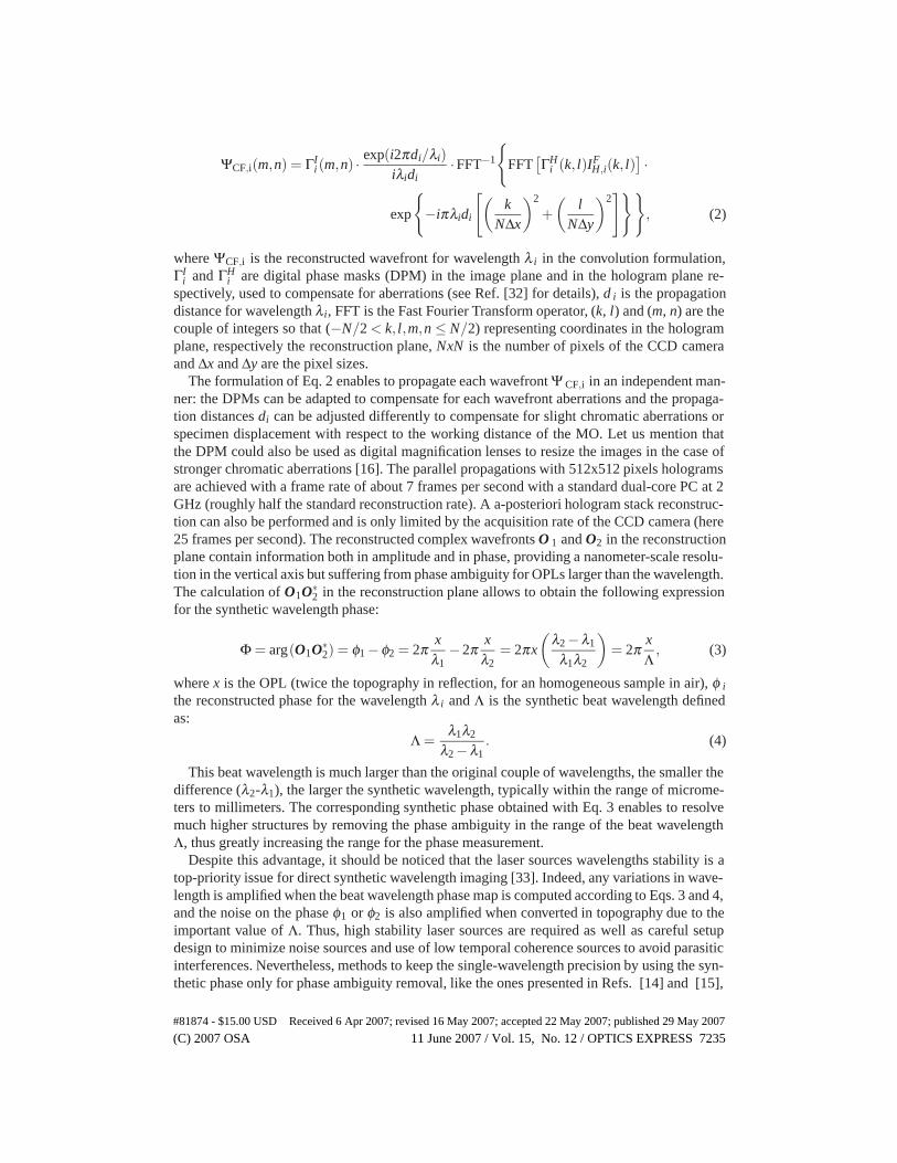
The formulation of Eq. 2 enables to propagate each wavefront Ψ CF,i in an independent man-ner: the DPMs can be adapted to compensate for each wavefront aberrations and the propaga-tion distances di can be adjusted differently to compensate for slight chromatic aberrations orspecimen displacement with respect to the working distance of the MO. Let us mention thatthe DPM could also be used as digital magnification lenses to resize the images in the case ofstronger chromatic aberrations [16]. The parallel propagations with 512x512 pixels hologramsare achieved with a frame rate of about 7 frames per second with a standard dual-core PC at 2GHz (roughly half the standard reconstruction rate). A a-posteriori hologram stack reconstruc-tion can also be performed and is only limited by the acquisition rate of the CCD camera (here25 frames per second). The reconstructed complex wavefronts O 1 and O2 in the reconstructionplane contain information both in amplitude and in phase, providing a nanometer-scale resolu-tion in the vertical axis but suffering from phase ambiguity for OPLs larger than the wavelength.The calculation of O1O∗
2 in the reconstruction plane allows to obtain the following expressionfor the synthetic wavelength phase:
Φ = arg(O1O∗2) = φ1 −φ2 = 2π
xλ1
−2πx
λ2= 2πx
(λ2 −λ1
λ1λ2
)= 2π
xΛ
, (3)
where x is the OPL (twice the topography in reflection, for an homogeneous sample in air), φ i
the reconstructed phase for the wavelength λ i and Λ is the synthetic beat wavelength definedas:
Λ =λ1λ2
λ2 −λ1. (4)
This beat wavelength is much larger than the original couple of wavelengths, the smaller thedifference (λ2-λ1), the larger the synthetic wavelength, typically within the range of microme-ters to millimeters. The corresponding synthetic phase obtained with Eq. 3 enables to resolvemuch higher structures by removing the phase ambiguity in the range of the beat wavelengthΛ, thus greatly increasing the range for the phase measurement.
Despite this advantage, it should be noticed that the laser sources wavelengths stability is atop-priority issue for direct synthetic wavelength imaging [33]. Indeed, any variations in wave-length is amplified when the beat wavelength phase map is computed according to Eqs. 3 and 4,and the noise on the phase φ1 or φ2 is also amplified when converted in topography due to theimportant value of Λ. Thus, high stability laser sources are required as well as careful setupdesign to minimize noise sources and use of low temporal coherence sources to avoid parasiticinterferences. Nevertheless, methods to keep the single-wavelength precision by using the syn-thetic phase only for phase ambiguity removal, like the ones presented in Refs. [14] and [15],
#81874 - $15.00 USD Received 6 Apr 2007; revised 16 May 2007; accepted 22 May 2007; published 29 May 2007
(C) 2007 OSA 11 June 2007 / Vol. 15, No. 12 / OPTICS EXPRESS 7235
can potentially nullify this effect and render the technique more forgiving regarding wavelengthstability.
At this point, if we compute the phase difference Φ (Eq. 3) for each reconstructed hologram,it becomes possible to measure, in real time, the object under investigation as if a source ofwavelength Λ were used. In this paper, the methods is demonstrated with live measurements onsamples up to 2μm high with a synthetic wavelength of Λ = 6.4μm.
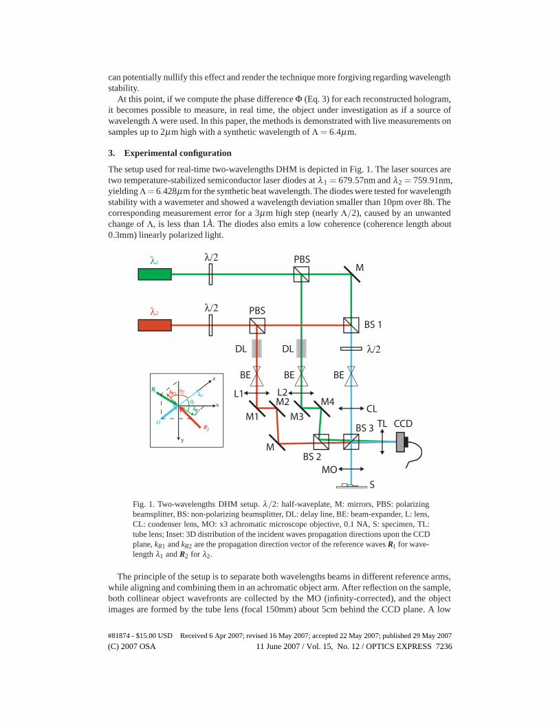
3. Experimental configuration
The setup used for real-time two-wavelengths DHM is depicted in Fig. 1. The laser sources aretwo temperature-stabilized semiconductor laser diodes at λ1 = 679.57nm and λ2 = 759.91nm,yielding Λ = 6.428μm for the synthetic beat wavelength. The diodes were tested for wavelengthstability with a wavemeter and showed a wavelength deviation smaller than 10pm over 8h. Thecorresponding measurement error for a 3μm high step (nearly Λ/2), caused by an unwantedchange of Λ, is less than 1A. The diodes also emits a low coherence (coherence length about0.3mm) linearly polarized light.
λ1
λ2
λ/2
λ/2
λ/2
PBS
PBSBS 1
BS 2
BS 3
DL DL
BE BE BE
M
M1
M2
M3
M4
M
L1 L2
CL
MO
TL CCD
z
x
y
O
R1
R2
θ1
θ2R2
kR1
kOk
S
Fig. 1. Two-wavelengths DHM setup. λ/2: half-waveplate, M: mirrors, PBS: polarizingbeamsplitter, BS: non-polarizing beamsplitter, DL: delay line, BE: beam-expander, L: lens,CL: condenser lens, MO: x3 achromatic microscope objective, 0.1 NA, S: specimen, TL:tube lens; Inset: 3D distribution of the incident waves propagation directions upon the CCDplane, kR1 and kR2 are the propagation direction vector of the reference waves R1 for wave-length λ1 and R2 for λ2.
The principle of the setup is to separate both wavelengths beams in different reference arms,while aligning and combining them in an achromatic object arm. After reflection on the sample,both collinear object wavefronts are collected by the MO (infinity-corrected), and the objectimages are formed by the tube lens (focal 150mm) about 5cm behind the CCD plane. A low
#81874 - $15.00 USD Received 6 Apr 2007; revised 16 May 2007; accepted 22 May 2007; published 29 May 2007
(C) 2007 OSA 11 June 2007 / Vol. 15, No. 12 / OPTICS EXPRESS 7236

magnification x3 MO, with a NA of 0.1, is used in the present case to achieve large field-of-view(FOV), 1x1mm2 with 512x512 pixels, and a large depth-of-field of more than 50μm. We canmention that there is no limitation regarding the use of higher magnification. The CCD camerais a standard 8 bits black and white CCD camera with 6.45μm pixel size. Each reference armcomprise a delay line (DL) adjusted to match the optical path length of its respective objectcounterparts, in order to create an interference on the CCD for both wavelengths. By tiltingthe pair of mirrors M1 and M2 for the first wavelength reference beam, respectively M3 andM4 for the second one, one can finely tune each k-vector incident upon the CCD camera. Inother words, each wavelength interferograms fringes can be independently tuned both in spatialfrequency and orientation.
The ideal configuration for dual-wavelength DHM is the one depicted in the inset of Fig. 1,with orthogonal spatial frequencies for each wavelength interferogram, because it ensures anoptimum repartition of the interference terms in the hologram Fourier domain, minimizing over-laps. A typical dual-wavelength hologram and its Fourier spectrum are represented in Fig. 2,with the real and virtual images components for each wavelength interferogram and the orthog-onal fringes regimes.
(a) (b)
R2*O2 R1*O1
Fig. 2. (a) Two-wavelengths hologram with the inset representing a zoom on the centralfringes, where the orthogonal spatial frequencies can be seen; (b) Fourier-spectrum of (a)(the zero order is filtered to enhance visibility), where the virtual images for each wave-length are easily separately spatial-filtered (red = 760nm, green = 680nm)
As can be seen in Fig. 2, the orthogonal repartition of the fringes spatial frequencies enablesto filter (select) separately the spatial frequencies of each wavelength in the Fourier spectrumof the hologram. In other words, the real image components R iO∗
i , or the virtual image compo-nents R∗
i Oi, or any other set of interference terms, can be selected independently as depicted inFig. 2(b), and this procedure is rendered easier by the clearly visible cut-off frequency of theMO (colored circles in Fig. 2(b). This experimental configuration for recording holograms isvery similar to the one in Ref. [27,28] and permits to encode both wavefronts with only a singleacquisition thanks to orthogonal carrier frequencies. It can also be noted that the circle is a bitlarger at 680nm, indicating a slightly higher cut-off frequency at this wavelength. A transverseresolution of 4.4μm has been measured with a USAF 1950 resolution test target and the systemis diffraction-limited according to the NA of the MO.
It is however important to mention that there is a trade-off here, in the sense that by usingoff-axis holography it is indeed possible to separate the terms in the spatial frequency domain,
#81874 - $15.00 USD Received 6 Apr 2007; revised 16 May 2007; accepted 22 May 2007; published 29 May 2007
(C) 2007 OSA 11 June 2007 / Vol. 15, No. 12 / OPTICS EXPRESS 7237

thus enabling single-acquisition imaging, but at the cost of a reduction by a factor two of thefield of view compared to in-line holography, where the full sampling efficiency of the CCDcan be exploited. That is, one need to use a higher magnification factor in off-axis holographythan with in-line holography to prevent resolution loss due to the use of only half the CCDsampling capability.
Once each wavelength interference term, here the two virtual images components, isspatially-filtered, one can use Eq. 2 to reconstruct and propagate each wavefront in the convo-lution formalism. By correcting for aberrations in the hologram plane before the propagation,especially the tilt, the reconstructed images are naturally centered [16]. This perfect superposi-tion and the achromatic design of the object arm of the setup, allow for an accurate subtractionof the wavefronts in the image plane. The reconstruction distances in the experimental config-uration of Fig. 1 are d1 = 50mm for λ1 = 680nm and d2 = 50.5mm for λ2 = 760nm and theycorrespond to the distances between the image planes and the CCD plane. As the reconstructiondistances difference is very small due to the achromatic conditions, the magnification differencecan be considered negligible and the superposition conditions are fulfilled.
For this setup, a high quality mirror has permitted to evaluate an experimental noise of about2 degrees of phase spatial standard deviation over the whole field-of-view in phase for eachwavefront. It should be noted that this spatial standard deviation value is the same as for single-wavelength DHM. This is valid for a single hologram reconstruction with contribution of boththe setup noise and the shot noise, at the instant of acquisition, which corresponds to a specklenoise for this frame. The time-dependant part of the noise, mainly shot noise for instance, canbe reduced by temporal averaging methods if necessary. When considering the synthetic beatphase Φ, the spatial standard deviation raises to about 3 degrees. In terms of axial topographicresolution, this corresponds to about 2nm precision for monochromatic phases, and 27nm forthe beat-wavelength phase precision, which is a consequence of the noise amplification phe-nomena. The standard deviation value for the synthetic phase is directly related to the propertythat the variance of the sum (or difference) of two Gaussian-noise distributions is the sum of theindividual variances: we have precisely here a
√2 amplification for the standard deviation when
considering the phase difference of two signals with quasi-identical standard deviations. Let usonce again point out that the same method as in Refs. [14] and [15] could be used to keepthe single-wavelength precision by solving the phase ambiguity with the synthetic phase map,and then adding integer multiple of one of the two wavelengths to the corresponding single-wavelength phase map. For such solutions to work, the noise level should be kept below λ i/4Λ[14], which is largely the case in our experimental configuration, but this condition may not bealways satisfied for e.g. noisy data or high-range beat wavelengths.
4. Results
To validate the technique, we have choosen a purely-reflective object with abrupt steps of morethan half a visible-range wavelength in height. Such a specimen cannot be observed with mono-chromatic DHM because the phase ambiguity is nearly impossible to solve with the help of un-wrapping algorithms, due to the steep transitions compared to the lateral resolution. The objectis a micro-structured SiO2 staircase on a Si wafer with a gold coating to ensure a perfect reflec-tivity. It is made of five steps with the following height values: 375, 525, 975, 1200, 1275nminducing up to 2.5μm in term of OPL, which represents about four times a typical red-rangewavelength and out of range of classical single-wavelength DHM. A schematic of this test-object and experimental reconstruction images of this sample from the hologram of Fig. 2 withthe two-wavelength setup of Fig. 1 are presented in Fig. 3
#81874 - $15.00 USD Received 6 Apr 2007; revised 16 May 2007; accepted 22 May 2007; published 29 May 2007
(C) 2007 OSA 11 June 2007 / Vol. 15, No. 12 / OPTICS EXPRESS 7238

(b)
(c)
(a) (d)
(e)
Fig. 3. (a) Schematic of the investigated staircase test-sample; (b,c) amplitude and (d,e)phase of respectively the reconstructed wavefront O1 (λ1 = 680nm, d1 = 5cm) andO2 (λ2 = 760nm, d2 = 5.05cm) obtained from the same hologram presented in Fig. 2(grayscale: black = -180, white = +180 for the phase; field-of-view: 1x1mm2)
The two reconstructed quantitative phase-contrast images of the object in Fig. 3(d,e) obtainedfrom the same hologram recording (Fig. 2) illustrate the phase ambiguity for single-wavelengthimaging: the smallest step of 375nm is invisible in Fig. 3(e) because it corresponds to an OPLof 750nm, which is nearly the value of λ2 = 760nm. Unwrapping algorithms are clearly uselessfor such micro-structures investigation. As we have recorded both wavefronts with the samehologram acquisition, the computation of the phase difference between Figs. 3(d) and 3(e) canbe achieved according to Eq. 3. After inversion of the sign of the phase to render a topographicmap (i.e. a conjugated phase map), as will be done for all synthetic phase-maps further on,we obtain the Λ = 6.428μm synthetic wavelength conjugated phase distribution presented inFig. 4.
(b)(a)
Fig. 4. Single-hologram beat-wavelength conjugated phase map of the sample of Fig. 3 atΛ = 6.428μm (grayscale: black = -180, white = +180). (a) Synthetic phase-contrast imageof the Si staircase sample at Λ = 6.428μm; (b) 3D perspective of (a).
#81874 - $15.00 USD Received 6 Apr 2007; revised 16 May 2007; accepted 22 May 2007; published 29 May 2007
(C) 2007 OSA 11 June 2007 / Vol. 15, No. 12 / OPTICS EXPRESS 7239

The measurement of the object with a beat-wavelength of Λ = 6.428μm straightforwardlyprovides a phase jumps-free result and a real 3D-topography of this up to 1.275μm high speci-men as illustrated in Fig. 4(b). To assess the method, quantitative profiles measurements on thesynthetic map of Fig. 4 are given in Fig. 5 and compared with results obtained with a whitelight interferometer.
-2000
200400600800
100012001400
0 100 200 300 400 500 600 700 800 900x [um]
Hei
ght [
nm]
Dual-wavelength DHM White light interferometer
-2000
200400600800
100012001400
0 100 200 300 400 500 600 700 800 900x [um]
Hei
ght [
nm]
Dual-wavelength DHM White light interferometer(a)
(b)
Fig. 5. (a) Profile line taken along the white line in Fig. 4(a) superposed with a profileobtained with a commercial white light interferometer; (b) spatial average of about 100profiles taken perpendicular to the small edge of the white rectangle defined in Fig. 4(a)compared with the average profile measured with the white light interferometer.
As can be seen in Fig. 5, the quantitative experimental results with two-wavelengths DHMare in agreement with the white-light interferometry results and within the manufacturing er-ror of 2% of the theoretical topographic values. Despite the standard deviation of the beat-wavelength phase of ∼ 27nm, it is still easily possible to discriminate the 1.2μm and 1.275μmsteps. Furthermore, the precision can be enhanced by spatially averaging 100 profiles as inFig. 5(b), where the measure seems even more accurate than with the white light interferome-ter. This spatial averaging is done for a single reconstruction, and it applies on both the setupand the speckle noise (shot noise at the instant of acquisition).
Nevertheless, the requirement to record only a single digital hologram is the true added-valueof the method. Thus, to demonstrate the real-time capability of the technique, the sample ismanually translated in one direction during 40s along different sizes of SiO 2 staircases with thesame heights staircases, and the sequence is recorded at the maximum frame rate of 25 images/s(1’000 acquisitions). Results illustrating the real-time synthetic wavelength phase maps arepresented as multimedia movies in Fig. 6.
#81874 - $15.00 USD Received 6 Apr 2007; revised 16 May 2007; accepted 22 May 2007; published 29 May 2007
(C) 2007 OSA 11 June 2007 / Vol. 15, No. 12 / OPTICS EXPRESS 7240

(a) (b) (c)
Fig. 6. Real-time beat-wavelength phase imaging by DHM. (a) Scanning orientationmap on the micro-structures array; (b) 40s movie of the Λ = 6.428μm phase-contrastimage at 25 images/s (test target ph.mov, 2.62 MB); (c) 3D perspective view of (b)(test target 3D.mov, 2.6 MB)
The real-time capability illustrated above is especially useful for moving samples measure-ments on a conveyor belt, in a similar way like with the translation in Fig. 6, or movingMEMS/MOEMS parts monitoring either in real-time or in stroboscopic mode [34]. To illus-trate this advantage of the method, Fig. 7 presents a 6 seconds movie (25 frames/second, 150acquisitions) of the phase reconstruction of a electrically-actuated 4x4mm 2 micro-mirror oscil-lating at 1Hz, for a single wavelength [Fig. 7(a)] and for synthetic wavelength [Fig. 7(b,c)].
(a) (c)(b)
Fig. 7. Dual-wavelength phase measurements on a moving micro-mirror oscillating at 1Hzduring 6s at 25 frames/s. (grayscale: black = -180, white = +180; field-of-view: 1x1mm2)(a) Phase movie at the wavelength λ1 = 680nm (mems 680nm.mov, 2.79 MB); (b) Phasemovie at the beat wavelength Λ = 6.428μm (mems beat wav.mov, 1.72 MB); (c) 3-D per-spective of (b) (mems 3D.mov, 2.6 MB
Figure 7 shows clearly the efficiency of the synthetic wavelength imaging, free of phasejumps, for such moving micro-parts investigation. Figure 8 demonstrates the usefulness ofdual-wavelength real-time DHM and its ideal application for MEMS/MOEMS investigation byproviding quantitative height measurements expressed by a profile line taken through the wholefield of view (FOV) during half-a-period of oscillation (0.5s). In addition the dual-wavelengthmethod is more robust than a time unwrapping that could be applied for a single wavelength.Indeed, if the mirror raises more than a few hundred of nanometers (λ i/2) between two acqui-sition (as for example between 0.12 and 0.25 second in Fig. 8), a temporal phase unwrappingmethod may fail.
#81874 - $15.00 USD Received 6 Apr 2007; revised 16 May 2007; accepted 22 May 2007; published 29 May 2007
(C) 2007 OSA 11 June 2007 / Vol. 15, No. 12 / OPTICS EXPRESS 7241

-200
0
200
400
600
800
1000
1200
1400
1600
1800
2000
0 100 200 300 400 500 600x [um]
Hei
gth
[nm
]
t = 0 t = 0.12s t = 0.25s t = 0.37s t = 0.5s
x-axis
Fig. 8. Half-a-period monitoring of micro-mirror movements at the synthetic wavelengthΛ = 6.428μm
5. Conclusion
We have presented a method to achieve real-time dual-wavelength digital holographic mi-croscopy with a single hologram acquisition. The principle is based on a spatial multiplexing ofthe hologram by incoherent addition of single-wavelength interferograms, each having differentpropagations directions for the reference waves. The property of off-axis digital holography toseparately extract the spatial frequencies associated to each wavefront, and to propagate them inparallel, permits to reconstruct the synthetic wavelength phase distribution of a reflective objectwith a single acquisition. Consequently, the dynamic range of phase measurements is increasedand the phase ambiguity of single-wavelength imaging is removed. Results obtained with ourmethod on a 1.2μm high test-target imaged at 25 frames/s with a 6.4μm synthetic wavelengthare in good agreement with white light interferometer measurements. Further on, this methodallows for observing fast phenomena and the dynamic performance has been illustrated with a1Hz oscillating micro-mirror monitoring at video frequency.
The development of the technology has been supported by Swiss government through CTIgrants TopNano 21 #6101.3 and NanoMicro #6606.2 and #7152.1. The author thanks the peopleat Lyncee Tec SA (www.lynceetec.com) for their collaboration and the fruitful discussions.
#81874 - $15.00 USD Received 6 Apr 2007; revised 16 May 2007; accepted 22 May 2007; published 29 May 2007
(C) 2007 OSA 11 June 2007 / Vol. 15, No. 12 / OPTICS EXPRESS 7242