real-time communicationfaculty.cs.tamu.edu/bettati/courses/663/2009c/slides/rtcomm.pdfreal-time...
TRANSCRIPT
CPSC-663: Real-Time SystemsReal-Time Communication
1
Real-Time Communication
• Integrated Services: Integration of variety of services withdifferent requirements (real-time and non-real-time)
• Traffic (workload) characterization
• Scheduling mechanisms
• Admission control / Access control (policing)
• Deterministic vs. stochastic analysis– Traffic characterization– Performance guarantees
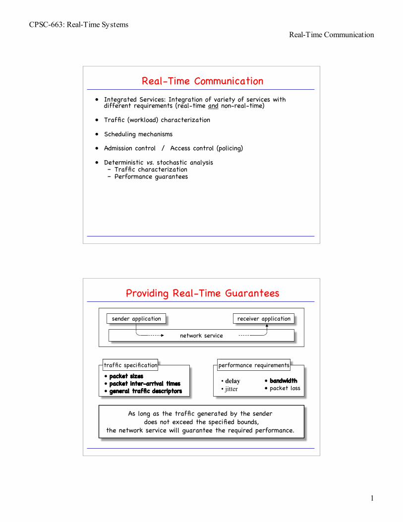
performance requirementstraffic specification
Providing Real-Time Guarantees
network service
sender application receiver application
• packet sizes• packet inter-arrival times• general traffic descriptors
• delay• jitter
• bandwidth• packet loss
As long as the traffic generated by the sender does not exceed the specified bounds,
the network service will guarantee the required performance.

CPSC-663: Real-Time SystemsReal-Time Communication
2
network service
Real-Time Guarantees: Mechanisms
sender application receiver application
deterministicpacket schedulingin switchesand routers
Enforcement:• policing• traffic shaping
connection-orientedservice
rigorous (and robust)delay computation
real-time-connection establishment
Traffic Description: Traffic Bounding Functions
• Arrival as stochastic processA = {A(t), t ≥ 0}
• A and a are poor traffic descriptors:– time dependent
• Deterministic traffic arrival descriptors (time-independent)– Maximum Traffic Function b(I) ≥ maxt>0{A(t+I) – A(t)}
– Maximum Rate Function b(I)/I ≥ maxt>0{A(t+I) – A(t)}/I
t
rate[b/sec]
A(t)
a(t)
CPSC-663: Real-Time SystemsReal-Time Communication
3
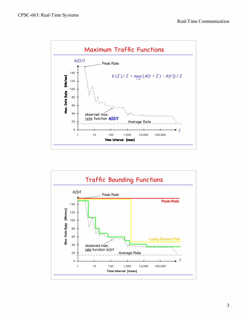
Maximum Traffic Functions
Time Interval [msec]
0
20
40
60
80
100
120
140
1 10 100 1,000 10,000 100,000
M
ax. Dat
a Rat
e
[Mb/
sec]
Peak Rate
Average Rate
observed max.rate function b(I)/I
I
b(I)/I
ItAItAIIbt
/))()((max/)(0
−+=≥
Traffic Bounding Functions
Time Interval [msec]
0
20
40
60
80
100
120
140
1 10 100 1,000 10,000 100,000
M
ax. D
ata
Rat
e [
Mb/
sec]
Peak Rate
Average Rate
observed max.rate function b(I)/I
Peak-Rate
Leaky Bucket Pair
I
b(I)/I
CPSC-663: Real-Time SystemsReal-Time Communication
4
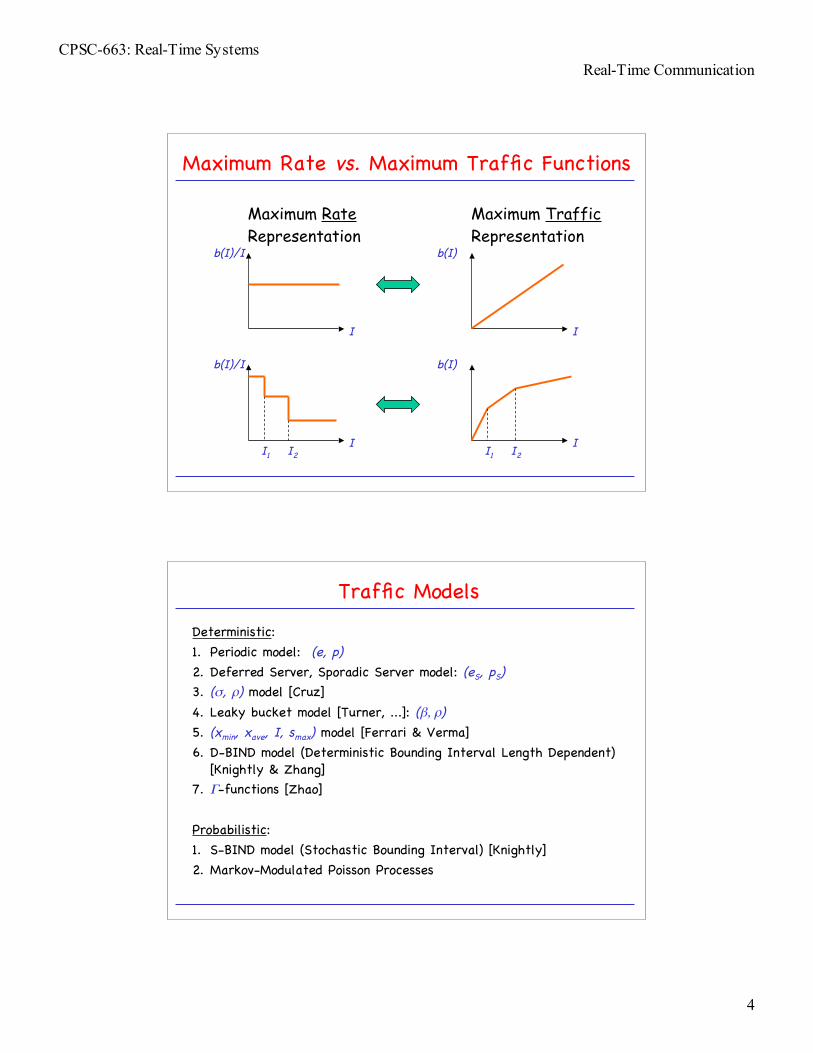
Maximum Rate vs. Maximum Traffic Functions
Maximum Rate Representation
b(I)/I
I
b(I)/I
I
Maximum Traffic Representation
b(I)
I
b(I)
II1 I2 I1 I2
Traffic Models
Deterministic:1. Periodic model: (e, p)2. Deferred Server, Sporadic Server model: (eS, pS)3. (σ, ρ) model [Cruz]4. Leaky bucket model [Turner, ...]: (β, ρ)5. (xmin, xave, I, smax) model [Ferrari & Verma]6. D-BIND model (Deterministic Bounding Interval Length Dependent)
[Knightly & Zhang]7. Γ-functions [Zhao]
Probabilistic:1. S-BIND model (Stochastic Bounding Interval) [Knightly]2. Markov-Modulated Poisson Processes

CPSC-663: Real-Time SystemsReal-Time Communication
5
Traffic Bounding Function b(.)
• Let b(.) be a monotonically increasing function.• b(.) is a deterministic traffic constraint function of a connection
if during any interval of length I, the number of bits arrivingduring the interval is no greater than b(I).
• Let A[t1,t2] be the number of packets arriving during interval[t1,t2]. Then, b(.) is a traffic constraint function if
• Each model defines inherently a traffic constraint function.• The accuracy of models can be compared by comparing their
constraint functions.
Cruz’ (σ, ρ) Model
• If the traffic is fed to a server that works at rate ρ while there iswork to be done, the size of the backlog will never be larger than σ.
• IOW: The number of jobs/cells released during any interval I does notexceed ρI+σ.
• Graphical representation:
I
wor
st c
ase
num
ber b
(.)of
jobs
/cel
ls re
leas
ed
σ
ρ
CPSC-663: Real-Time SystemsReal-Time Communication
6
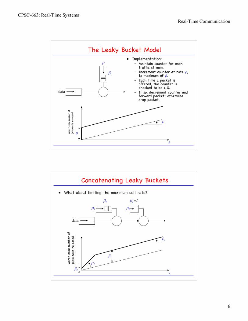
The Leaky Bucket Model• Implementation:
– Maintain counter for eachtraffic stream.
– Increment counter at rate ρ,to maximum of β.
– Each time a packet isoffered, the counter ischecked to be > 0.
– If so, decrement counter andforward packet; otherwisedrop packet.
β
ρ
data
I
wors
t ca
se n
umbe
r of
jo
bs/c
ells
rel
ease
d
β
ρ
Concatenating Leaky Buckets
• What about limiting the maximum cell rate?
β1
ρ1
data
β2=1
ρ2
x
wor
st c
ase
numbe
r of
jo
bs/c
ells r
elea
sed
β1
ρ1
ρ2
β2

CPSC-663: Real-Time SystemsReal-Time Communication
7
(xmin, xave, Iave, smax) model [Ferrari & Verma]
• xmin : minimum packet interarrival time• xave : average packet interarrival time• Iave : averaging interval length• smax : maximum packet length
I
wor
st c
ase
numbe
r of
jo
bs/c
ells r
elea
sed 1/xave
1/xmin
Iave
maxmin
maxmin ,modmin))(,,,( sII
xI
xItIsIxxb
aveave
aveaveaveave
+
=
D-BIND [Knightly & Zhang]
• Other models do not accurately describe burstiness.• Rate-interval representation:
interval length [sec]
boun
ding
rate
[Mbp
s]
long-term average rate
1.6
0.5 1.0
lecture
advertisements
• Model traffic by multiple rate-interval pairs: (Rk, Ik), where rate Rk isthe worst-case rate over every interval of length Ik.

CPSC-663: Real-Time SystemsReal-Time Communication
8
D-BIND (2)
• Constraint function for D-BIND model with P rate-interval pairs:
• Comparison:
interval length
D-BIND
(σ, ρ)xmin, ...
max
imum
bits
PP
kkkkkkk
kkkk
ItIttbtb
b
ItIIRItII
IRIRtb
>−=
=
≤≤+−−
−=
−
−
−−
for )/()(
0)0(
,)()( 11
11
Policing for the D-BIND Model
• Lemma: If b(t) is piece-wise linear concave, then Rk isstrictly decreasing with increasing Ik.
• Lemma: If a piece-wise linear constraint function b(t) withP linear segments is concave, then the source maybe fully policed with a cascade of P leaky buckets.
link rate
concave hull
CPSC-663: Real-Time SystemsReal-Time Communication
9
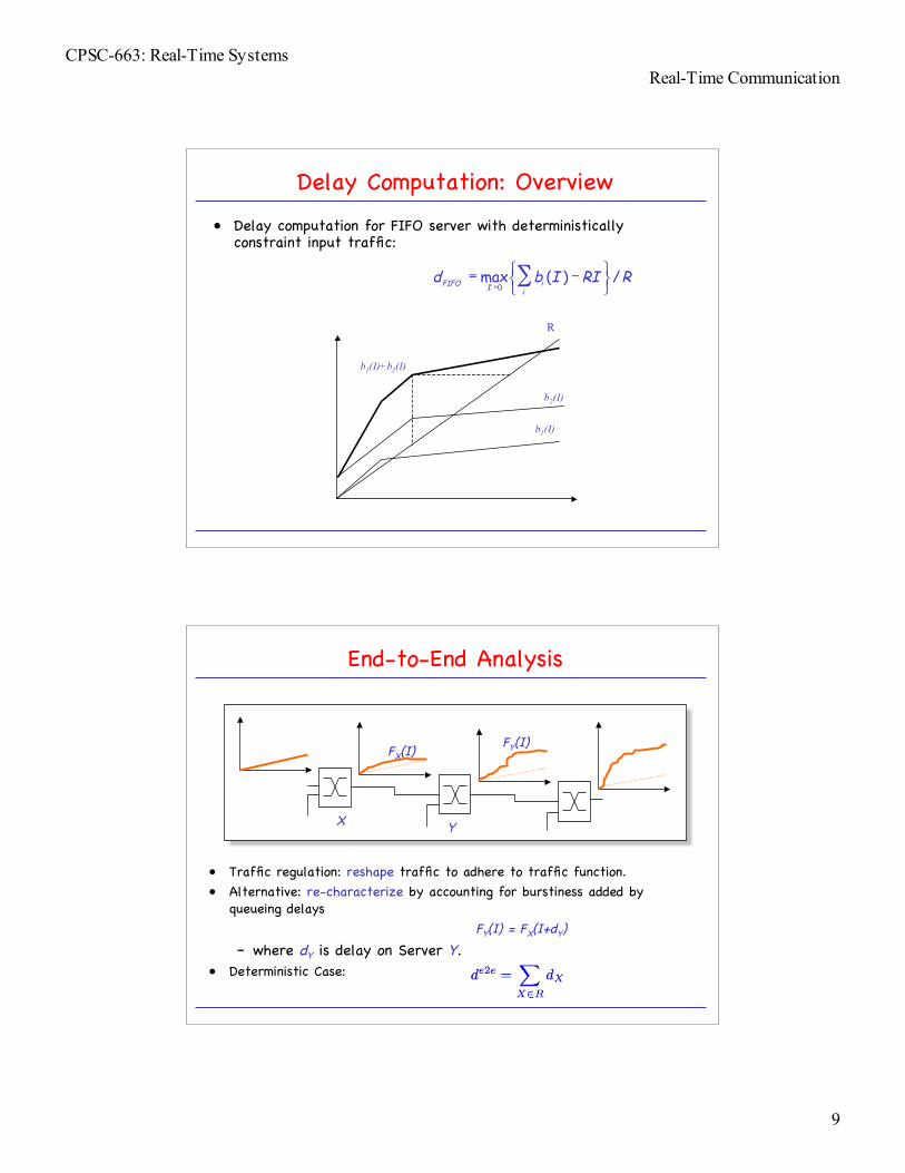
Delay Computation: Overview
• Delay computation for FIFO server with deterministicallyconstraint input traffic:
R
b1(I)
b2(I)
b1(I)+b2(I)
RRIIbdi
iIFIFO /)(max0
−= ∑
>
End-to-End Analysis
• Traffic regulation: reshape traffic to adhere to traffic function.• Alternative: re-characterize by accounting for burstiness added by
queueing delaysFY(I) = FX(I+dY)
– where dY is delay on Server Y.• Deterministic Case:
X Y
FX(I)FY(I)

CPSC-663: Real-Time SystemsReal-Time Communication
10
Switch Scheduling
• Work-conserving (greedy) vs. non-work-conserving (non-greedy)mechanisms.
• Rate-allocating disciplines: Allow packets to be served at higherrates than the guaranteed rate.
• Rate-controlled disciplines: Ensures each connection the guaranteed rate, but does not allow packets to be served aboveguaranteed rate.
• Priority-based scheduling:– fair queuing– virtual clock– earliest due date (EDD)– rate-controlled static
priority (RCSP)
• Weighted Round-Robin scheduling:– WRR
Bit-by-Bit Weighted Round-Robin
• bit-by-bit round robin• each connection is given
a weight• each queue served in
FIFO order
wi

CPSC-663: Real-Time SystemsReal-Time Communication
11
Fair Queueing [Demers, Keshav, Shenker]
• Emulate Bit-by-Bit Round Robin by prioritizing packets.• Prioritize packets on basis of their finish time fj:
– aj: arrival time of j-th packet– ej: length of packet– fj: finish time– BW: allocated fraction of link bandwidth
• Example:
• Complications:– What if connections dynamically change?
1 4 1.5 1 1
BWeaff jjjj /),max( 1+=
−
Virtual Clock Algorithm [L.Zhang]
• Emulate time-division multiplex (TDM) mechanism• However:
– TDM: when some connections idle, the slots assigned are idle– VC: idle slots are deleted from TDM frames
• auxiliary virtual clock (auxVCj): finish time of j-th packet.• virtual tick (Vtickj) :time to complete transmission of ready j-th
packet.Vtickj = ej/BW
• Replace fj by Vtickj: VC becomes identical to WFQ algorithm!
• Will analyze delay analysis later.

CPSC-663: Real-Time SystemsReal-Time Communication
12
Rate-Controlled Static Priority (RCSP) [Zhang&Ferrari]
priorityqueues
RCSP (2)
ratecontroller
priorityqueues
CPSC-663: Real-Time SystemsReal-Time Communication
13
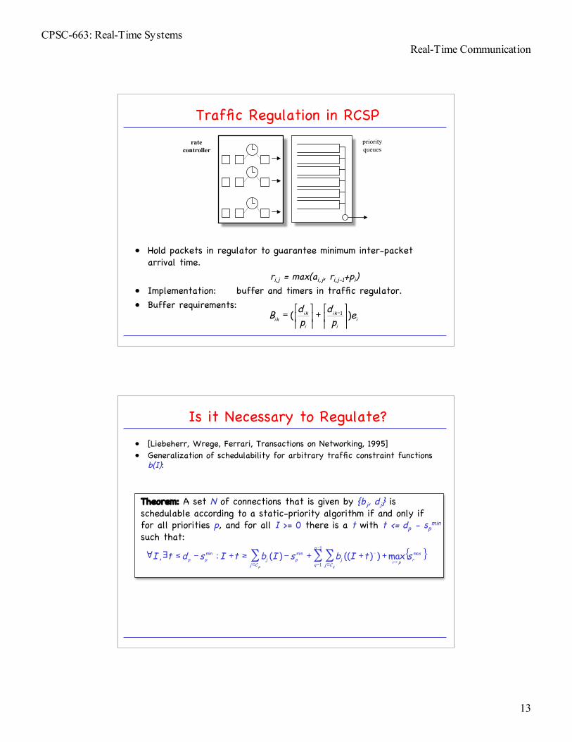
Traffic Regulation in RCSP
• Hold packets in regulator to guarantee minimum inter-packetarrival time.
ri,j = max(ai,j, ri,j-1+pi)• Implementation: buffer and timers in traffic regulator.• Buffer requirements:
ratecontroller
priorityqueues
ii
ik
i
ikik e
pd
pdB )( 1
+
= −
Is it Necessary to Regulate?
• [Liebeherr, Wrege, Ferrari, Transactions on Networking, 1995]• Generalization of schedulability for arbitrary traffic constraint functions
b(I):
Theorem: A set N of connections that is given by {bj, dj} isschedulable according to a static-priority algorithm if and only iffor all priorities p, and for all I >= 0 there is a t with t <= dp - sp
min
such that:
{ }max1
1
minmin max))(()(:, rpr
p
q Cjjp
Cjjpp stIbsIbtIsdtI
qp>
−
= ∈
−
∈
+++−≥+−≤∃∀ ∑∑∑
CPSC-663: Real-Time SystemsReal-Time Communication
14
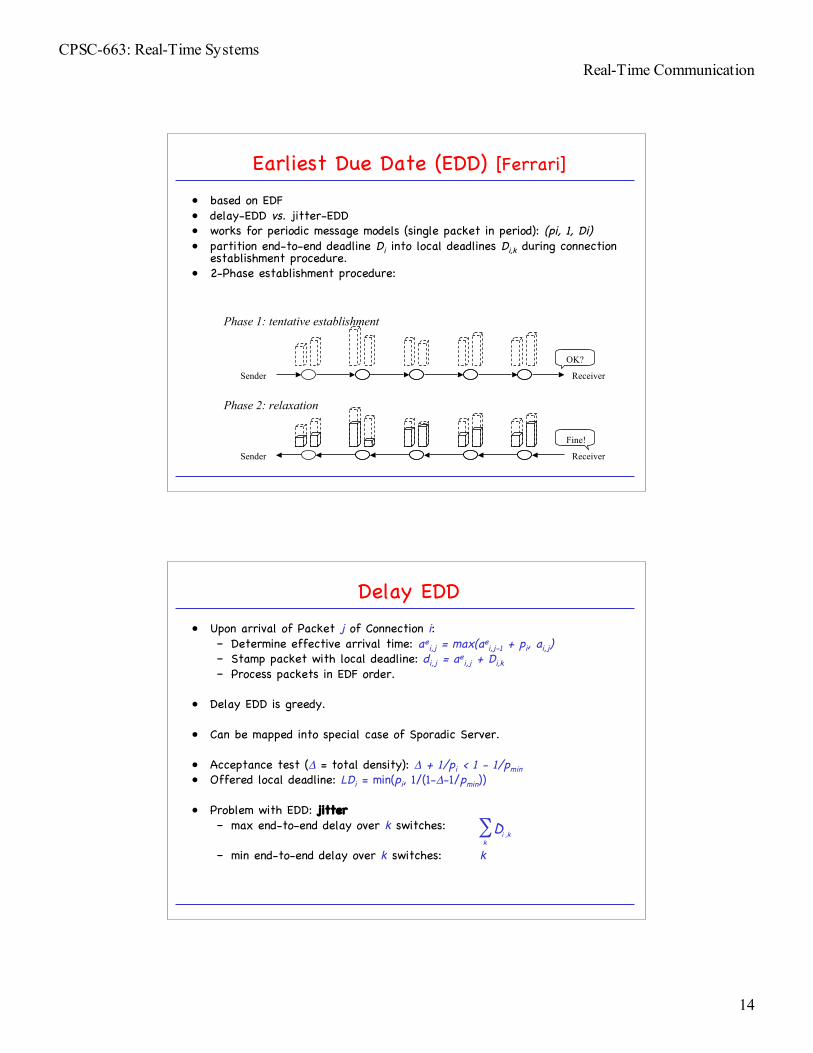
Earliest Due Date (EDD) [Ferrari]
• based on EDF• delay-EDD vs. jitter-EDD• works for periodic message models (single packet in period): (pi, 1, Di)• partition end-to-end deadline Di into local deadlines Di,k during connection
establishment procedure.• 2-Phase establishment procedure:
Sender Receiver
OK?
Sender Receiver
Fine!
Phase 1: tentative establishment
Phase 2: relaxation
Delay EDD
• Upon arrival of Packet j of Connection i:– Determine effective arrival time: ae
i,j = max(aei,j-1 + pi, ai,j)
– Stamp packet with local deadline: di,j = aei,j + Di,k
– Process packets in EDF order.
• Delay EDD is greedy.
• Can be mapped into special case of Sporadic Server.
• Acceptance test (Δ = total density): Δ + 1/pi < 1 - 1/pmin• Offered local deadline: LDi = min(pi, 1/(1-Δ-1/pmin))
• Problem with EDD: jitter– max end-to-end delay over k switches:
– min end-to-end delay over k switches: k
∑k
kiD ,

CPSC-663: Real-Time SystemsReal-Time Communication
15
Jitter EDD• Problem with Delay-EDD: does not control jitter. This has effect
on buffer requirements.• Jitter-EDD maintains Ahead Time ahi,j, which is the difference
between local relative deadline Di,k-1 and actual delay at Switchk-1.
• Ahead time is stored in packet header (alternatively, we useglobal time synchronization)
• Upon receiving the j-th packet of Connection i with ahi,j at timeai,j:– Calculate ready time as Switch k:
aei,j=max(ae
i,j-1 + pi , ai,j)ri,j = max(ae
i,j , ai,j + ahi,j)– Stamp packet with deadline di,j=ri,j+Di,k and process according
to EDF starting from ready time ri,j.• Result: Regenerate traffic at each switch.
Rate Control vs. Jitter Control
• Rate Control
• Jitter Control

CPSC-663: Real-Time SystemsReal-Time Communication
16
Simple EDF with Arbitrary Arrival Functions[Liebeherr, Wrege, Ferrari: Transactions on Networking, 1995]
Theorem: A set Π of connections that is given by {bi; di} iεΠ and di ≤dj whenever i<j is EDF schedulable if and only if for all I ≥ d1:
where
Informal “proof”: A deadline violation occurs at time I if themaximum traffic arrivals with deadline before or at time I, i.e.
exceeds I.
{ }∑Π∈ >
+−≥j
kIdkjj sdIbIk
max,
max)(
{ } { }kkkIdk
dI for , sk Π∈>
>≡ max0max max,
∑Π∈
−<j
jj dIbI )(
• For some traffic models, closed-form expressions for theschedulability test exist.
• For (σ, ρ) traffic:
• A closed form for the delay can be given as follows:
EDF Test for Special Cases: Example (σ,ρ)
{ }
≥−+≥
Π<≤<≤+−+≥
Π
Π
=
+>=
∑
∑
dIdII
jdIdsdII
iiii
jjkjk
j
iiii
for )(
1:for max)(
1
1max
1
ρσ
ρσ
{ }
∑
∑−
=
−
=>
−
+−+=
1
1
1
1
max
1
max)(j
ii
j
ikjkiiij
j
sdd
ρ
ρσσ

CPSC-663: Real-Time SystemsReal-Time Communication
17
Weighted Round Robin (WRR)
• Traffic model:– periodic (pi, ei, Di)– variable bit rate models possible
• Realizations:– greedy WRR– Stop-and-Go (SG)– Hierarchical Round Robin (HRR)
• Each connection i is assigneda weight wi, i.e., it isallocated wi slots during eachround.
• Slot: time to transmitmaximum-sized packet.
wi
Throughput and Delay Guarantees
• Each connection i is guaranteed wi slots in each rounds.• Round length RL : upper bound on sum of weights (design parameter)
• Constraints:
1.
2.
• Delays:
– at first switch:– downstream: once packet passes first
switch, it is immediately eligible onswitches downstream -> has to waitat most RL=> end-to-end delay through N
switches:
RL p≤min
≥
RLpew
i
ii
w RLi≤∑
RLwe
i
i
( ) RLNpRLNweW iiii )1(1 −+≤−+≤

CPSC-663: Real-Time SystemsReal-Time Communication
18
• Greedy WRR does not control jitter:
• min end-to-end delay: ei +(N-1)• max end-to-end delay: pi +(N-1)RL• jitter: pi-ei +(N-1)(RL-1)
• Buffer needed at k-th switch for Connection i:
• Need traffic shaping at each switch.
Problems with Greedy WRR
ii epRLk )/)1)(1(1( −−+
First Switch
Non-Greedy WRR
• Actual length of rounds in greedy WRR varies with amount oftraffic at switch.
• Non-greedy WRR schemes fix round length into fixed-lengthframes.
• Stop-and-Go [Golestani]
• Hierarchical Round Robin [Kalmanek, K., K.]

CPSC-663: Real-Time SystemsReal-Time Communication
19
Stop & Go [Golestani, 1990]
• Frame-based: divide time in frames of length RL.• Packet arriving during frame at input link is eligible for transmission during next
frame on output link.
• Stop-and-Go is not work-conserving.• Traffic model [(r, RL) smooth traffic]: during each frame of length RL,
the total number of bits transmitted by source does not exceed rRL bits.
• Proposition: If the connection satisfies (r,RL) smoothness at the input ofthe first server, and each server ensures that packets will always goout on the next departing frame, the connection will satisfy (r,RL)smoothness at each server throughout the network.
input frames
output frames
input frames
Stop & Go: Implementation
• Implementation of scheduler is not defined by Stop-and-Goframeworks.
• Implementation 1: FIFO scheduler with double-queue structure
• Implementation 2:

CPSC-663: Real-Time SystemsReal-Time Communication
20
• Hierarchical framing with n levels with frame sizes RL1, ..., RLn, whereRLm+1=KmRLm for m = 1, ..., n-1.
• Stop-and-Go rule for packets of level-p connection: Packets that arrivedduring a RLp frame will not become eligible until the start of the nextRLp frame.
• Packets with smaller frame size have higher priority (non-preemptively)over packets with larger frame size.
Multi-Frame Stop-and-Go[For example, Zhang&Knightly: “Comparison of RCSP and SG”, ACM Multimedia, 4(6) 1996]
• Problem with Stop-and-Go (or any other frame-based approach): delay-bandwidth coupling– Delay of packet is bounded by a multiple of frame time. This is a
problem, for example for low-bandwidth, low-delay connections.(Why?)
• Solution: Use multi-level framing. Example:
RL1
RL2
Hierarchical Round Robin[Kalmanek, Kanadia, Keshav, 1990]
• End-to-end delay and jitter of S&G depends on RL only.• How about having multiple S&G servers, with different RL’s, and
multiplex them on the same outgoing link?
wiRLx
swx
• Server X is seen as periodic stream of requests by Server S, with– ex = swx, px = RLx, Dx = RLx– schedule using rate-monotonic scheduler– Configuration time test: check whether task set {(swx,RLx,RLx)} is schedulable.
• Admission Control Test:– Bandwidth test: check sum of required wi’s <= swx– Delay test: End-to-end delay: pi + N RLx– Jitter test: 2 RLx, with buffer requirement 2 wi
Server X
Server S