real instruction set architectures set to make programmers’ task easier –extensive set of data...
TRANSCRIPT

Real instruction set
architectures
Part 2: a representative sample

Some historical architectures
• VAX: Digital’s line of midsize computers,
dominant in academia in the 70s and 80s
• Characteristics:
– Variable-length instructions; anywhere from 2 to 5
operands
– Full set of addressing modes: operands can be
anywhere; single instruction could take up to 31 bytes
– “High level” instructions: complexity built into
instruction set to make programmers’ task easier
– Extensive set of data types at machine level

Variable-length VAX instructions
• Logical & arithmetic operations have 2 or 3
operands
• String operations have 3 or 5 operands

VAX addressing modes
• Anyplace you could have an operand, you could
have any addressing mode, e.g.:
– to/from register
– to/from memory location
– to/from address referenced by register
– to/from address referenced by memory location
– to/from address offset from base address in register
– to/from address offset from base address in memory
– etc.

VAX “high-level” instructions
• Intended to simplify life for assembly
programmers & compiler writers – some
examples:
– ACB: add, compare & branch – useful for count-
controlled loops
– CASE: for switch/case statements
– CALLG: procedure call with general argument list
– POLY: for polynomial evaluation (gets next
coefficient, performs multiply & accumulate)

VAX data types
• Has the standard set: byte, word, floating-
point word
• Includes instructions that support:
– variable-length character strings
– variable-length bit fields
– numeric strings
– packed decimal strings
– queues

Some historical architectures
• Motorola’s 68000 series
– Initial Apple MacIntosh, early Sun
workstations
– Variable-length instructions: 0-2 operands
– Wide variety of addressing modes (but not as
many as VAX)

Performance issues in 68000
• A consequence of 2-operand instructions
(in which one of the operands is also the
storage destination), is that the same
hardware component (such as a register)
must be accessed several times in a
single instruction
• Result: one instruction must be completed
before the next one can begin – effectively
prevents use of pipelining

Intel architectures
• 8086 chip: first produced in 1979
– Handled 16-bit data, 20-bit addresses
– Could address 1 million bytes of memory
– CPU split into 2 parts:
• Execution unit: contained GPRs & ALU
• Bus interface unit: included instruction queue,
segment registers, instruction pointer (SR & IP are
special-purpose registers)

8086 GPRs
• AX: accumulator
• BX: base register: could be used to extend
addressing
• CX: count register
• DX: data register
• Some 8086 instructions require use of
specific GPR, but in general, could use
any of these to hold data

Byte-level addressing
• Each GPR addressable at word or byte
level
• For example, AX divided into:
– AH (contains MSB)
– AL (contains LSB)
• Same for BX, CX, DX
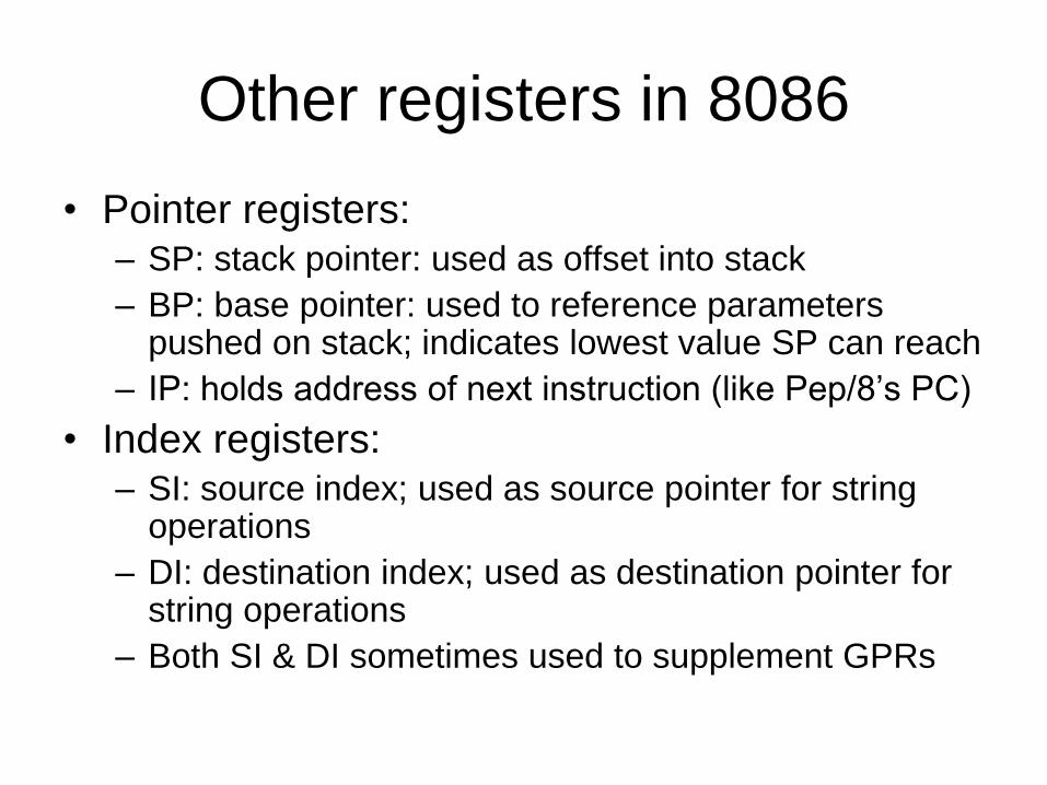
Other registers in 8086
• Pointer registers: – SP: stack pointer: used as offset into stack
– BP: base pointer: used to reference parameters pushed on stack; indicates lowest value SP can reach
– IP: holds address of next instruction (like Pep/8’s PC)
• Index registers: – SI: source index; used as source pointer for string
operations
– DI: destination index; used as destination pointer for string operations
– Both SI & DI sometimes used to supplement GPRs
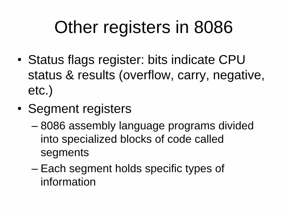
Other registers in 8086
• Status flags register: bits indicate CPU
status & results (overflow, carry, negative,
etc.)
• Segment registers
– 8086 assembly language programs divided
into specialized blocks of code called
segments
– Each segment holds specific types of
information

8086 Segments
• Code segment: program itself
(instructions)
• Data segment: program data
• Stack segment: program’s runtime stack
(for procedure calls)

8086 segments
• To access information in a segment, had to specify item’s offset from segment start
• Segment needed to store segment addresses – these were stored in segment registers: – CS: code segment
– DS: data segment
– SS: stack segment
– ES: extra segment (used by some string operations to handle memory addressing)
• Addresses specified in segment/offset form: XXX:YYY
Where XXX is the value stored in a segment register, and YYY is the offset from the start of the segment

Evolution of Intel platform
• Basic 8086 ISA used in many successor
chips:
– 8087
• Introduced in 1980
• Added floating-point instructions, 80-bit stack
– 80286
• Introduced 1982
• Could address up to 16Mb of memory

Evolution of Intel platform
• 80386
– Could address 4Gb of RAM
– 32-bit chip, with 32-bit bus, 32-bit word
– To achieve backward compatibility, Intel kept same basic architecture, register sets
– Used new naming convention in registers: EAX, EBX, etc. were 32-bit (extended) versions of AX, BX, etc.; could still access original 16-bit registers (and their byte components) using original names

Evolution of Intel platform
• 80486
– Added high-speed cache memory for performance
improvement
– Integrated math co-processor
• Pentium™ series
– Intel quit using numbers: couldn’t trademark them
– 32-bit registers, 64-bit bus
– Employed superscalar design, with multiple ALUs;
could run instructions in parallel, handling more than
one instruction per clock cycle

Pentium™ series
• Pro added branch prediction
• II added MMX
• III added increased support for 3D
graphics using floating-point instructions
• P4: 1.4 GHz and higher clock rates; 42
million transistors per CPU; 400MHz (and
faster) system bus, refinements to cache &
floating-point operations

Pentium™ series
• Itanium: Intel’s first 64-bit chip
– Employs hardware emulator to maintain
backward compatibility with x86
– 4 integer ALUs, 4 floating-point ALUs, 4
cache levels, 128 bit registers for integers and
floating-point numbers
– Multiple miscellaneous registers for dealing
with efficient instruction loading for branching
– Addresses up to 16Gb of RAM

CISC vs. RISC
• CISC: complex instruction set computing
– Employed by Intel up through Pentium Pro
– Pentium II and III used combined CISC/RISC: CISC
architecture with RISC core that could translate CISC
instructions to RISC
• RISC: reduced instruction set computing
• CISC emphasizes complexity in hardware,
simplicity in software; RISC is opposite
• RISC is generally considered superior in
performance

Fetch/execute cycle & pipelining
• In the examples we’ve looked at this far, an underlying theme has been the use of one or more clock cycles per instruction, with additional cycles necessary to control details within certain steps
• Modern CPUs break the fetch/execute cycle into smaller steps, some of which can be performed in parallel, speeding up execution
• This method of overlapping instructions is called pipelining

Pipelining
• We can break the fetch/execute cycle into 6 general steps: – Fetch instruction
– Decode
– Calculate operand address(es)
– Fetch operands
– Execute instruction
– Store result
• Each step can be considered a pipeline stage; goal is to balance time taken by each stage, so that slower ports of process don’t bog down faster parts

Standard von Neumann model vs.
pipelining
Source:
http://www.cs.cmu.edu/afs/cs/academic/class/15745-s06/web/handouts/11.pdf

Pipelining issues
• Although not all instructions require every
stage of pipeline (e.g. no operand) all
instructions proceed through all stages
• Pipeline conflicts:
– resource conflicts
– data dependencies
– conditional branch statements

Intel & pipelining
• 8086-80486 were single-stage pipeline
architectures
• Pentium: 2 five-stage pipelines
– Pentium II increased to 12 (mostly for MMX)
– Pentium III: 14
– Pentium IV: 24

MIPS: a RISC architecture
• Little-endian
• Word-addressable
• Fixed-length instructions
• Load-store architecture:
– only LOAD & store operations have RAM access
– all other instructions must have register operands
– requires large register set
• 5 or 8 stage pipelining

Intel machine language
… and a little bit of 80x86
assembly language
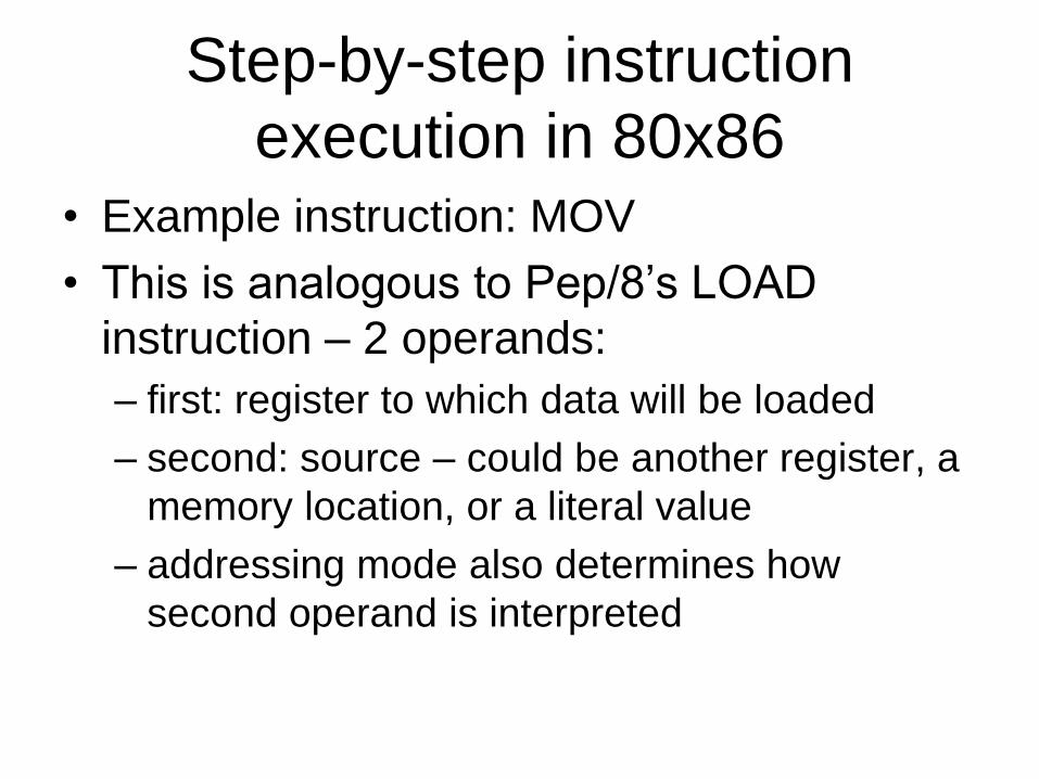
Step-by-step instruction
execution in 80x86 • Example instruction: MOV
• This is analogous to Pep/8’s LOAD
instruction – 2 operands:
– first: register to which data will be loaded
– second: source – could be another register, a
memory location, or a literal value
– addressing mode also determines how
second operand is interpreted

Steps involved in MOV
1. Fetch instruction byte from memory (1
clock cycle)
2. Update IP to point to next byte (1 clock
cycle)
3. Decode instruction (1 clock cycle)

Steps involved in MOV
4. If required, fetch 16-bit instruction
operand from RAM (0-2 clock cycles)
– 0 cycles if no operand
– 1 cycle if 16-bit operand is word-aligned
(begins at even address)
– 2 if operand is not word-aligned (starts at
odd address)
5. If required, update IP to point past
operand (IP + 2): 0-1 clock cycles

Steps involved in MOV
6. If required, compute address of operand
(example: BX + offset) – 0-1 cycles
7. Fetch operand: 0-3 cycles
– if operand is literal value, 0
– if stored in register, 1
– if stored in word-aligned RAM, 2
– if stored in non-word-aligned RAM, 3
8. Store fetched value in destination register
Total clock cycles for MOV: 5-11

MOV memory location, register
1. Fetch instruction (1)
2. Update IP to point to next byte (1)
3. Decode instruction
4. If required, fetch operand from memory (0-2)
5. If required, update IP to point beyond operand (0-1: 0 if no operand)
6. Compute operand address, if necessary (0-2)
7. Get value (of register) to store (1)
8. Store fetched value into destination (1-3)

Data manipulation instructions
• Includes: add, sub, cmp, and, or, not
• First operand is a register; second may
require memory fetch
• Takes 8-17 clock cycles, as described on
next slide

Data manipulation instructions
1. Fetch instruction (1)
2. Update IP (1)
3. Decode (1)
4. If required fetch operand from memory • if [BX] mode: (0)
• if [xxxx], [xxxx+ BX] or xxxx & address is even: (1)
• if xxxx & address odd: (2)
5. If required, update IP to point beyond operand
(0-1)

Data manipulation instructions
6. Compute address of operand • if not [BX] or [xxxx+BX]: (0)
• if [BX]: (1)
• if [xxxx+BX]: (2)
7. Get value of operand & send to ALU • if constant: (0)
• if register: (1)
• if word-aligned RAM: (2)
• if odd-addressed RAM: (3)

Data manipulation instructions
8. Fetch value of first operand (register) &
send to ALU (1)
9. Perform operation (1)
10.Store result in 1st operand (register) (1)

Encoding x86 instructions
• Size variation: 8 or 24 bit
• 8-bit opcode always present
• 16-bit field (after opcode) present if:
– instruction is a JMP (branch to new
instruction)
– operand uses indexed or direct addressing
– operand is an immediate value

x86 instruction format: 1st 8 bits
I I I R R M M M
I fields: instruction
000: special
001: OR
010: AND
011: CMP
100: SUB
101: ADD
110: MOV (register destination)
111: MOV (RAM destination
R fields: register
00: AX
01: BX
10: CX
11: DX
M fields: operand specifier
000: AX
001: BX
010: CX
011: DX
100: [BX]
101: [BX + offset]
110: [offset]
111: literal value

“Special” instructions:
expanding opcodes • If the first 3 bits of the first byte (opcode)
are 000, the byte is interpreted in a
different way than presented on the
previous slide
• The “special” instruction format provides a
way for x86 processors to have a fixed-
size instruction but allows for many more
instructions than would be possible with
just a 3-bit opcode

Expanding opcodes
0 0 0 I I M M M
First 3 bits: 000 Instruction bits:
00: 0 operand instruction
01: jumps
10: not
11: illegal
If instruction bits indicate a NOT, the operand specifier bits (MMM) are
read as follows:
000: AX 100: [BX]
001: BX 101: [BX + offset]
010: CX 110: [offset]
011: DX 111: literal value

0-operand instructions
0 0 0 0 0 I I I
First 5 bits are 0s; last 3 bits give instruction specification:
000, 001, 010: illegal
011 BRK
100 IRET (return from interrupt)
101 HALT
110 get
111 put
Last two are not real instructions
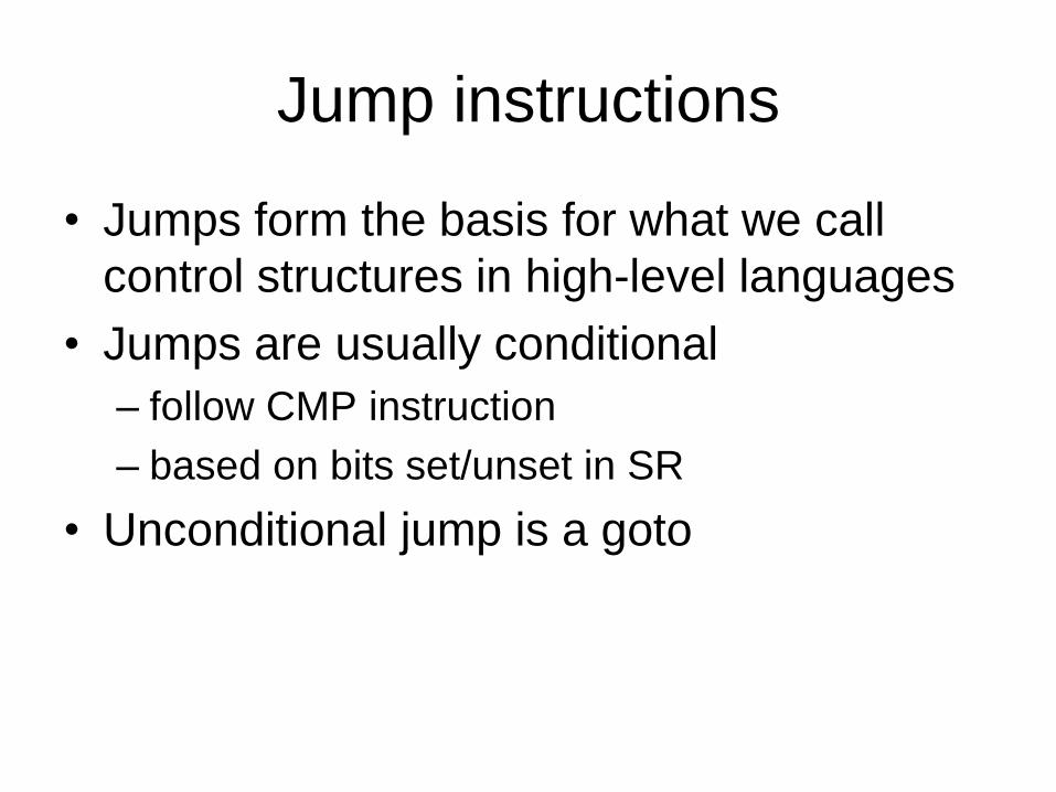
Jump instructions
• Jumps form the basis for what we call
control structures in high-level languages
• Jumps are usually conditional
– follow CMP instruction
– based on bits set/unset in SR
• Unconditional jump is a goto

Jump instructions
0 0 0 1 0 I I I
First 3 bits indicate special, next two indicate jump; instruction specifier bits
(last 3) indicate type of jump:
000: JE
001: JNE
010: JL
011: JLE
100: JG
101: JGE
110: JMP
111: illegal

80x86 looping example
WHILESTART:
CMP AX, DX
JG AFTERLOOP
…
ADD AX, 1
JMP WHILESTART
AFTERLOOP:

Conditional jump execution:
fetch/execute cycle 1. Fetch instruction (1 clock cycle)
2. Update IP (1 clock cycle)
3. Decode instruction (1 clock cycle)
4. Fetch target address from memory
– 1 clock cycle if address is even
– 2 if address is odd

Fetch/execute cycle for
conditional jump 5. Update IP (1 clock cycle)
6. Test flags in SR (1 clock cycle)
7. If flags test true, copy value into IP
The instruction is basically the same as
MOV register, value except the register in
question is IP