real analog - circuits 1 chapter 1: circuit analysis fundamentals
TRANSCRIPT

Real Analog - Circuits 1 Chapter 1: Circuit Analysis Fundamentals
© 2012 Analog Devices and Digilent, Inc.
1
1. Introduction and Chapter Objectives
In this chapter, we introduce all fundamental concepts associated with circuit analysis. Electrical circuits are
constructed in order to direct the flow of electrons to perform a specific task. In other words, in circuit analysis
and design, we are concerned with transferring electrical energy in order to accomplish a desired objective. For
example, we may wish to use electrical energy to pump water into a reservoir; we can adjust the amount of
electrical energy applied to the pump to vary the rate at which water is added to the reservoir. The electrical
circuit, then, might be designed to provide the necessary electrical energy to the pump to create the desired water
flow rate.
This chapter begins with introduction to the basic parameters which describe the energy in an electrical circuit:
charge, voltage, and current. Movement of charge is associated with electrical energy transfer. The energy
associated with charge motion is reflected by two parameters: voltage and current. Voltage is indicative of an
electrical energy change resulting from moving a charge from one point to another in an electric field. Current
indicates the rate at which charge is moving, which is associated with the energy of a magnetic field. We will not
be directly concerned with charge, electrical fields or magnetic fields in this course, we will work almost
exclusively with voltages and currents. Since power quantifies the rate of energy transfer, we will also introduce
power in this chapter.
Electrical circuits are composed of interconnected components. In this chapter, we will introduce two basic types
of components: power supplies and resistors. Power supplies are used to provide power to our electrical circuits,
and resistors dissipate electrical power by converting it to heat. These two types of components will allow us to
introduce and exercise virtually all available circuit analysis techniques. Electrical components are described in
terms of the relationships between the voltages and currents at their terminals, these relationships are called the
voltage-current characteristics of the device. In this chapter, we will introduce voltage-current characteristics for
power supplies and resistors. In later chapters, we will introduce additional circuit components, but our circuit
analysis approaches will not change – we will simply substitute voltage-current characteristics for these
components as appropriate to model future circuits.
Finally, we introduce the two fundamental rules of circuit analysis: Kirchoff’s Current Law and Kirchoff’s
Voltage Law. These rules form the basis of all circuit analysis techniques used throughout this textbook.
Please pay special attention to the passive sign convention introduced in this chapter. Voltages and currents have
signs – they can be positive or negative – and these signs are crucial to understanding the effect of these
parameters on the energy transferred by the circuit. No useful circuit analysis can be performed without following
the passive sign convention.
In summary, this chapter introduces virtually all the basic concepts which will be used throughout this textbook.
After this chapter, little information specific to electrical circuit analysis remains to be learned – the remainder of
the textbook is devoted to developing analysis methods used to increase the efficiency of our circuit analysis and
introducing additional circuit components such as capacitors, inductors, and operational amplifiers. The student
should be aware, however, that all of our circuit analysis is based on energy transfer among circuit components;
this energy transfer is governed by Kirchoff’s Current Law and Kirchoff’s Voltage Law and the circuit
components are modeled by their voltage-current relationships.

Real Analog – Circuits 1 Chapter 1: Circuit Analysis Fundamentals
© 2012 Analog Devices and Digilent, Inc.
2
After completing this chapter, you should be able to:
Define voltage and current in terms of electrical charge
State common prefixes and the symbols used in scientific notation
State the passive sign convention from memory
Determine the power absorbed or generated by an circuit element, based on the current and voltage provided
to it
Write symbols for independent voltage and current sources
State from memory the function of independent voltage and current sources
Write symbols for dependent voltage and current sources
State governing equations for the four types of dependent sources
State Ohm’s Law from memory
Use Ohm’s Law to perform voltage and current calculations for resistive circuit elements
Identify nodes in an electrical circuit
Identify loops in an electrical circuit
State Kirchoff’s current law from memory, both in words and as a mathematical expression
State Kirchoff’s voltage law from memory, both in words and as a mathematical expression
Apply Kirchoff’s voltage and current laws to electrical circuits

Real Analog – Circuits 1 Chapter 1.1: Basic Circuit Parameters and Sign Conventions
© 2012 Analog Devices and Digilent, Inc.
3
1.1 Basic Circuit Parameters and Sign Conventions
This section introduces the basic engineering parameters for electric circuits: voltage, current, and power. The
international system of units is commonly used to describe the units of these parameters; this system as it relates
to electrical circuit analysis is briefly discussed in this section.
This section also introduces the passive sign convention. It is extremely important when analyzing electrical
circuits to use the correct sign convention between the voltage across a circuit element and the current going
through the element. Some of the most common errors of beginning students are associated with applying
incorrect sign conventions when analyzing circuits.
Electrical Charge:
Electron flow is fundamental to operation of electric circuits; the concept of charge can be used to describe the
distribution of electrons in the circuit. Charge can be represented as either positive or negative – generally
relative to some reference level. Charge is represented by the variable q and is measured in coulombs,
abbreviated as C. The charge of one electron corresponds to -1.602210-19
C. Charge can only exist in integer
multiples of the charge of a single electron. Charge, however, is not widely used in electrical circuit analysis;
voltage and current are more convenient ways to represent the electric charge in a system.
Voltage:
Voltage is energy per unit charge. Energy is specified relative to some reference level; thus, voltages are more
accurately specified as voltage differences between two points in a circuit. The voltage difference between two
points can be thought of as a difference in potential energy between charges placed at those two points. Units of
voltage are volts, abbreviated V. The voltage difference between two points indicates the energy necessary to
move a unit charge from one of the points to the other. Voltage differences can be either positive or negative.
Mathematically, voltage is expressed in differential form as:
dq
dwv (1.1)
where v is the voltage difference (in volts), w is the energy (in joules), and q is the charge (in coulombs). The
differences in equation (1.1) are all defined relative to different spatial positions; thus, the differentials dw and dq
are between two different points in space, and the voltage is defined as being between these same two spatial
points.
Current:

Real Analog – Circuits 1 Chapter 1.1: Basic Circuit Parameters and Sign Conventions
© 2012 Analog Devices and Digilent, Inc.
4
Current is the rate at which charge is passing a given point. Current is specified at a particular point in the circuit,
and is not relative to a reference. Since current is caused by charge in motion, it can be thought of as indicating
kinetic energy.
Mathematically, current is represented as:
dt
dqi (1.2)
where i is the current in amperes, q is the charge in coulombs, and t is time in seconds. Thus, current is the time
rate of change of charge and units of charge are coulombs per second or amperes (abbreviated as A).
Power:
An electrical system is often used to drive a non-electrical system (in an electric stove burner, for example,
electric energy is converted to heat). Interactions between electrical and non-electrical systems are generally
described in terms of power. Electrical power associated with a particular circuit element is the product of the
current passing through the element and the voltage difference across the element. This is often written as
)()()( titvtp (1.3)
where p(t) is the instantaneous power at time t, v(t) is the voltage difference at time t, and i(t) is the current at time
t. Power can be either absorbed by a circuit element or generated by a circuit element; the determination as to
whether the element is absorbing or generating power can be made by the relative signs of the values of voltage
and current. These sign conventions are an important issue, and will be addressed separately in the next chapter.
Units of power are watts, abbreviated W.

Real Analog – Circuits 1 Chapter 1.1: Basic Circuit Parameters and Sign Conventions
© 2012 Analog Devices and Digilent, Inc.
5
International System of Units and Prefixes:
We will use the international system of units (SI). The scales of parameters that are of interest to engineers can
vary over many orders of magnitudes. For example, voltages experienced during lightning strikes can be on the
order of 107 V, while voltages measured from an electroencephalograph (EEG) can be on the order of 10
-4 V. For
this reason, numbers represented in SI units are often associated with a prefix, which helps account for the order-
of-magnitude variations in numbers. Table 1 below provides a list of common prefixes and the symbols used to
represent them.
Multiple Prefix Symbol
109 giga G
106 mega M
103 kilo k
10-3
milli m
10-6
micro μ
10-9
nano n
10-12
pico p
Table 1.1. SI prefixes.
Thus, for example, a voltage of 107 V can be represented as 10 MV, or ―ten mega-volts‖.
Passive Sign Convention:
A general two-terminal electrical circuit element is shown in Figure 1.1. In general, there will be some current, i,
flowing through the element and some voltage difference, v, across its terminals. Note that we are currently
representing both voltage and current as constants, but none of the assertions made in this chapter change if they
are functions of time.
a
b
i
+
-
v
Real Analog – Circuits 1 Chapter 1.1: Basic Circuit Parameters and Sign Conventions
© 2012 Analog Devices and Digilent, Inc.
6
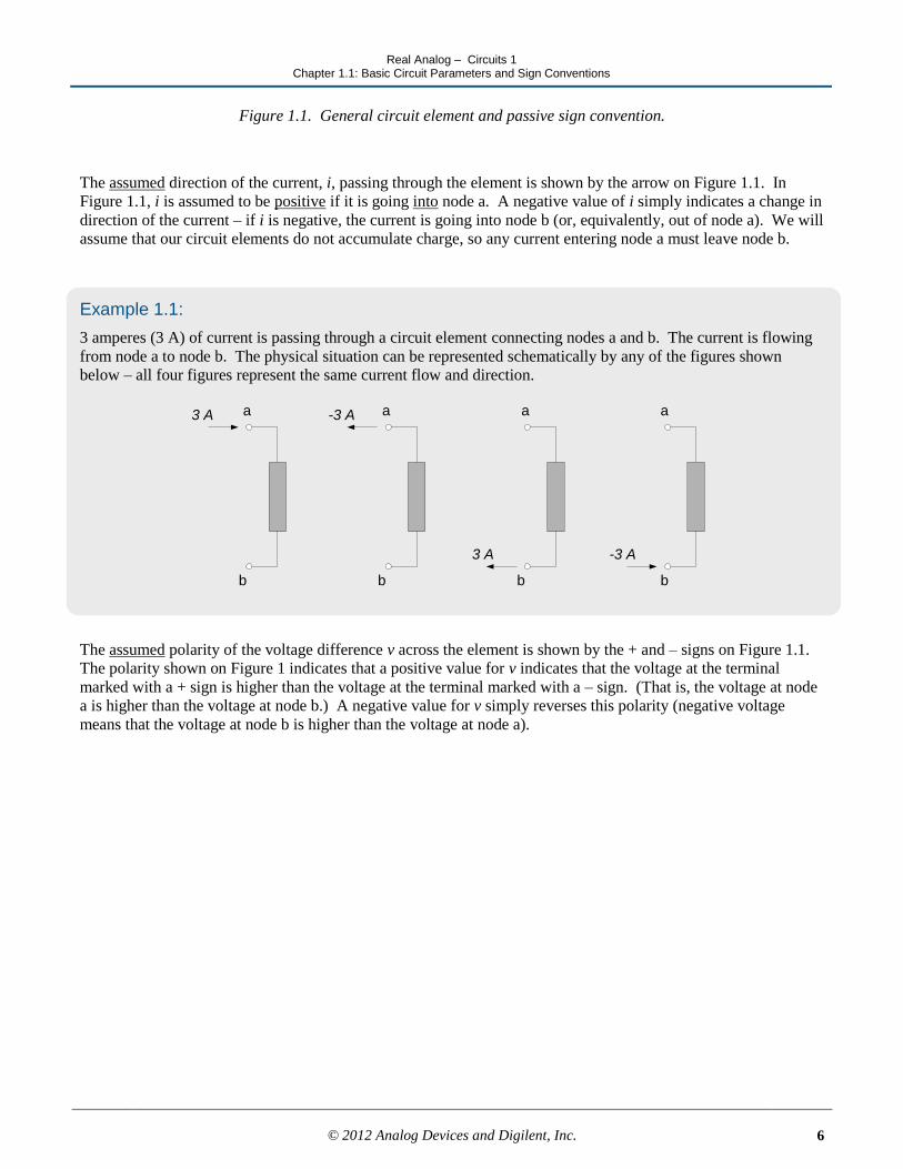
Figure 1.1. General circuit element and passive sign convention.
The assumed direction of the current, i, passing through the element is shown by the arrow on Figure 1.1. In
Figure 1.1, i is assumed to be positive if it is going into node a. A negative value of i simply indicates a change in
direction of the current – if i is negative, the current is going into node b (or, equivalently, out of node a). We will
assume that our circuit elements do not accumulate charge, so any current entering node a must leave node b.
Example 1.1:
3 amperes (3 A) of current is passing through a circuit element connecting nodes a and b. The current is flowing
from node a to node b. The physical situation can be represented schematically by any of the figures shown
below – all four figures represent the same current flow and direction.
3 A -3 A
3 A -3 A
b b b b
a a a a
The assumed polarity of the voltage difference v across the element is shown by the + and – signs on Figure 1.1.
The polarity shown on Figure 1 indicates that a positive value for v indicates that the voltage at the terminal
marked with a + sign is higher than the voltage at the terminal marked with a – sign. (That is, the voltage at node
a is higher than the voltage at node b.) A negative value for v simply reverses this polarity (negative voltage
means that the voltage at node b is higher than the voltage at node a).

Real Analog – Circuits 1 Chapter 1.1: Basic Circuit Parameters and Sign Conventions
© 2012 Analog Devices and Digilent, Inc.
7
Example 1.2:
A 5 volt (5 V) voltage potential difference is applied across a circuit element connecting nodes a and b. The
voltage at node a is positive relative to the voltage at node b. The physical situation can be represented
schematically by either of the figures shown below – both figures represent the same voltage potential difference.
b b
a a
+
-
5 V
+
-
-5 V
The assumed voltage polarity and current direction are not individually significant – the assumed direction of
voltage polarity relative to current direction is important. To satisfy our sign convention, we will assume that
positive current enters the node at which the positive voltage polarity is defined. This sign convention is called
the passive sign convention. In the passive sign convention, the relative assumed sign convention between
voltage and current is as shown in Figure 1.1.
Example 1.3:
The passive sign convention is satisfied for either of the two voltage-current definitions shown below – the
current is assumed to enter the positive voltage node.
+
-
v
+
-
v
i
i
The passive sign convention is not satisfied for either of the two voltage current definitions shown below – the
current is assumed to enter the negative voltage node.
+
-
v
+
-
v
i
i

Real Analog – Circuits 1 Chapter 1.1: Basic Circuit Parameters and Sign Conventions
© 2012 Analog Devices and Digilent, Inc.
8
Note:
Many students attempt to choose current directions and voltage polarities so that their calculations result in
positive values for voltages and currents. In general, this is a waste of time – it is best to arbitrarily assume either
a voltage polarity or current direction for each circuit element.
Choice of a positive direction for current dictates the choice of positive voltage polarity, per Figure 1.1. Choice
of a positive voltage polarity dictates the choice of positive current direction, per Figure 1.1.
Analysis of the circuit is performed using the above assumed signs for voltage and current. The sign of the results
indicates whether the assumed choice of voltage polarity and current direction was correct. A positive magnitude
of a calculated voltage indicates that the assumed sign convention is correct; a negative magnitude indicates that
the actual voltage polarity is opposite to the assumed polarity. Likewise, a positive magnitude of a calculated
current indicates that the assumed current direction is correct; a negative magnitude indicates that the current
direction is opposite to that assumed.
Voltage Subscript and Sign Conventions:
The assumed sign convention for voltage potentials is sometimes expressed by using subscripts. The first
subscript denotes the node at which the positive voltage polarity is assumed and the second subscript is the
negative voltage polarity. For example, vab denotes the voltage difference between nodes a and b, with node a
assumed as having positive voltage relative to node b. Switching the order of the subscripts changes the assumed
polarity of the voltage difference and thus the sign of the voltage, so vab = -vba. Since our passive sign convention
dictates the direction of current relative to voltage polarity, a circuit element whose voltage difference is denoted
as vab will have positive current entering node a.
Reference Voltages and Ground:
For convenience, voltages differences are often not explicitly stated as being differences between two potential
levels – a node will simply be referred to as having some ―voltage‖. This voltage must still be interpreted as a
voltage difference, however. The difference in this case, however, is assumed to be relative to some reference
voltage, with the reference generally assumed to be 0V. The reference voltage is often referred to as ground. The
symbol, , is used to denote the ground or reference voltage from which all other voltages are measured. When
this convention is used, voltages at a node are often identified with a single subscript. For example, va would be
the voltage at node a, relative to ground. It is assumed that positive voltages are positive relative to ground and
negative voltages are negative relative to ground.

Real Analog – Circuits 1 Chapter 1.1: Basic Circuit Parameters and Sign Conventions
© 2012 Analog Devices and Digilent, Inc.
9
Example 1.4:
The two figures below show identical ways of specifying the voltage across a circuit element. In the circuit to the
left, the voltage v is the voltage potential between nodes a and b, with the voltage at node a being assumed
positive relative to the voltage at node b. This can be equivalently specified as vab. In the figure to the right
below, node b has been specified as our ground with the use of the symbol. In this figure, the voltage at node
a can be specified simply as va, with the polarity being assumed positive relative to ground which is implied to be
0V. Thus, for the figures below,
aab vvv
a
b
+
-
v
va
Power and Sign Conventions:
The sign of the voltage across an element relative to the sign of the current through the element governs the sign
of the power. Equation (1.3) above defines power as the product of the voltage times current:
viP
The power is positive if the signs of voltage and current agree with the passive sign convention – that is, if
positive current enters the positive voltage polarity node. If the power is positive, the element is said to be
absorbing power. The power is negative if the signs of voltage and current disagree with the passive sign
convention – that is, if positive current enters the negative voltage polarity node. If the power is negative, the
element is said to be generating power.

Real Analog – Circuits 1 Chapter 1.1: Basic Circuit Parameters and Sign Conventions
© 2012 Analog Devices and Digilent, Inc.
10
Example 1.5:
In figure (a) below, the element agrees with the passive sign convention since a positive current is entering the
positive voltage node. Thus, the element of figure (a) is absorbing energy. In figure (b), the element is absorbing
power – positive current is leaving the negative voltage node, which implies that positive current enters the
positive voltage node. The element of figure (c) generates power; negative current enters the positive voltage
node, which disagrees with the passive sign convention. Figure (d) also illustrates an element which is generating
power, since positive current is entering a negative voltage node.
2 A 2 A
+
-
3V
+
-
3V
(a) 6W absorbed (b) 6W absorbed (c) 6W generated (c) 6W generated
-2 A
+
-
3V
2 A
+
-
3V

Real Analog – Circuits 1 Chapter 1.1: Basic Circuit Parameters and Sign Conventions
© 2012 Analog Devices and Digilent, Inc.
11
Section Summary:
In this text, we will be primarily concerned with the movement of electrical charge. Electrical charge motion
is represented by voltage and current. Voltage indicates the energy change associated with the movement of a
charge from one location to another, while current is indicative of the rate of current motion past a particular
point.
a. Voltage is an energy difference between two physically separated points. The polarity of a voltage is
used to indicate which point is to be assumed to be at the higher energy level. The positive terminal
(+) is assumed to be at a higher voltage than the negative terminal (-). A negative voltage value
simply indicates that the actual voltage polarity is opposite to the assumed polarity.
b. The sign of the current indicates the assumed direction of charge motion past a point. A change in the
sign of the current value indicates that the current direction is opposite to the assumed direction.
The assumed polarity of the voltage across a passive circuit element must be consistent with the assumed
current direction through the element. The assumed positive direction for current must be such that positive
current enters the positive voltage terminal of the element. Since this sign convention is applied only to
passive elements, it is known as the passive sign convention.
c. The assumed current direction or the assumed voltage polarity can be chosen arbitrarily, but once one
parameter is chosen, the other must be chosen to agree with the passive sign convention.
The power absorbed or generated by an electrical circuit component is the product of the voltage difference
across the element and the current through the element: ivp . The relative sign of the voltage and current
are set according to the passive sign convention. Positive power implies that the voltage and current are
consistent with the passive sign convention (the element absorbs or dissipates energy) while negative power
indicates that the relative signs between voltage and current are opposite to the passive sign convention (the
element generates or supplies energy to the circuit).

Real Analog – Circuits 1 Chapter 1.1: Basic Circuit Parameters and Sign Conventions
© 2012 Analog Devices and Digilent, Inc.
12
3. Determine the magnitude and direction of the current in the circuit element below if the element absorbs
10W.
Exercises:
1. Assign reference voltage and current directions to the circuit elements represented by the shaded boxes in the
circuits below.
(a)
+
-3V
Voltage
Source
(b)
2A
Current
Source
2. Either the reference voltage polarity or the reference current direction is provided for the circuit elements
below. Provide the appropriate sign convention for the missing parameters.
+
-9V
+
-
V3
+
-
V2
I1
I4
0.5A
Current
Source
Voltage
Source

Real Analog – Circuits 1 Chapter 1.1: Basic Circuit Parameters and Sign Conventions
© 2012 Analog Devices and Digilent, Inc.
13
+
-
2V
4. Determine the power absorbed or supplied by the circuit element below. State whether the power is absorbed
or supplied.
+
-
3V 2A

Real Analog – Circuits 1 Chapter 1.2: Power Sources
© 2012 Analog Devices and Digilent, Inc.
14
1.2 Power Sources
Circuit elements are commonly categorized as either passive or active. A circuit element is passive if the total
amount of energy it delivers to the rest of the circuit (over all time) is non-positive. (Passive elements can
temporarily deliver energy to a circuit, but only if the energy was previously stored in the passive element by the
circuit.) An active circuit element has the ability to create and provide power to a circuit from mechanisms
external to the circuit. Examples of active circuit elements are batteries (which create electrical energy from
chemical processes) and generators (which create electrical energy from mechanical processes, such spinning a
turbine).
In this section we consider some very important active circuit elements: voltage and current sources. We will
discuss two basic types of sources: independent sources and dependent sources. Independent sources provide a
specified voltage or current, regardless of what is happening elsewhere in the circuit to which they are
connected—batteries and generators are generally considered to be independent sources. Dependent sources
provide a voltage or current based on a voltage or current elsewhere in the circuit. (The source voltage or current
is dependent upon some other voltage or current.) Dependent sources are often used in the mathematical
modeling of common devices such as Metal Oxide Semiconductor Field Effect Transistors (MOSFETs) and
Bipolar Junction Transistors (BJTs).
Independent Voltage Sources:
An independent voltage source maintains a specified voltage across its terminals. The symbol used to indicate a
voltage source delivering a voltage vs(t) is shown in Figure 1.2. As indicated in Figure 1.2, the voltage supplied
by the source can be time varying or constant (a constant voltage is a special case of a time varying voltage). An
alternate symbol that is often used to denote a constant voltage source is shown in Figure 1.3; we, however, will
generally use the symbol of Figure 1.2 for both time-varying and constant voltages.
Note that the sign of the voltage being applied by the source is provided on the source symbol – there is no need
to assume a voltage polarity for voltage sources. The current direction, however, is unknown and must be
determined (if necessary) from an analysis of the overall circuit.
Ideal voltage sources provide a specified voltage regardless of the current flowing through the device. Ideal
sources can, obviously, provide infinite power; all real sources will provide only limited power to the circuit. We
will discuss approaches for modeling non-ideal sources in later chapters.
+
-vs(t)
Figure 1.2. Independent voltage source
Real Analog – Circuits 1 Chapter 1.2: Power Sources
© 2012 Analog Devices and Digilent, Inc.
15
V
+
-
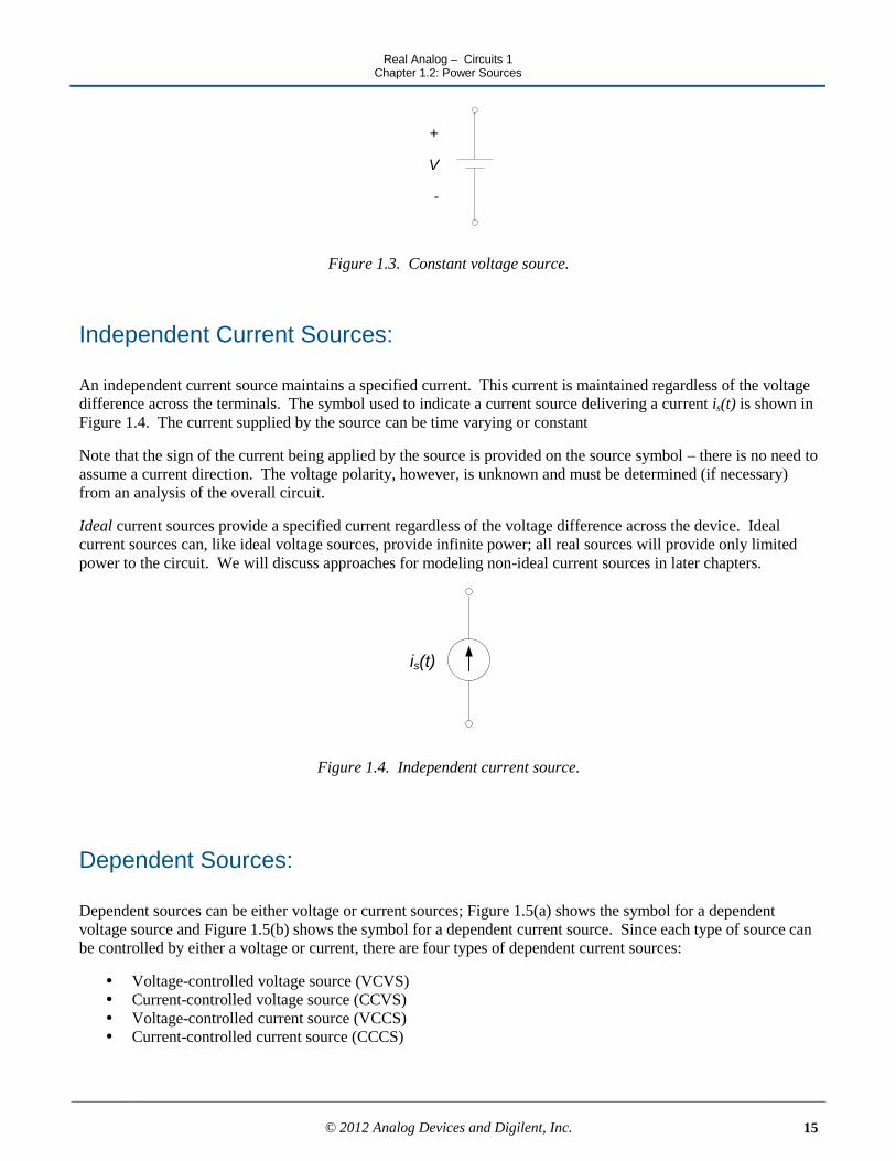
Figure 1.3. Constant voltage source.
Independent Current Sources:
An independent current source maintains a specified current. This current is maintained regardless of the voltage
difference across the terminals. The symbol used to indicate a current source delivering a current is(t) is shown in
Figure 1.4. The current supplied by the source can be time varying or constant
Note that the sign of the current being applied by the source is provided on the source symbol – there is no need to
assume a current direction. The voltage polarity, however, is unknown and must be determined (if necessary)
from an analysis of the overall circuit.
Ideal current sources provide a specified current regardless of the voltage difference across the device. Ideal
current sources can, like ideal voltage sources, provide infinite power; all real sources will provide only limited
power to the circuit. We will discuss approaches for modeling non-ideal current sources in later chapters.
is(t)
Figure 1.4. Independent current source.
Dependent Sources:
Dependent sources can be either voltage or current sources; Figure 1.5(a) shows the symbol for a dependent
voltage source and Figure 1.5(b) shows the symbol for a dependent current source. Since each type of source can
be controlled by either a voltage or current, there are four types of dependent current sources:
Voltage-controlled voltage source (VCVS)
Current-controlled voltage source (CCVS)
Voltage-controlled current source (VCCS)
Current-controlled current source (CCCS)

Real Analog – Circuits 1 Chapter 1.2: Power Sources
© 2012 Analog Devices and Digilent, Inc.
16
+
-v i
(a) Dependent voltage source (b) Dependent current source
Figure 1.5. Symbols for dependent sources
Figure 1.6 illustrates the voltage-controlled dependent sources, and Figure 1.7 illustrates the current-controlled
dependent sources. In all cases, some electrical circuit exists which has some voltage and current combination at
its terminals. Either the voltage or current at these terminals is used to set the voltage or current of the dependent
source. The parameters μ and β in Figures 1.6 and 1.7 are dimensionless constants. μ is the voltage gain of a
VCVS and β is the current gain of a CCCS. The parameter r is the voltage-to-current ratio of a CCVS and has
units of volts/ampere, or ohms. The parameter g is the current-to-voltage ratio of a VCCS and has units of
amperes/volt, or siemens. The units of ohms and siemens will be discussed in more depth in section 1.3.
Electrical
Circuit
i1
+
-
v1
+
-vs = mv1
Electrical
Circuit
i1
+
-
v1 is = gv1
(a) Voltage controlled voltage source (b) Voltage controlled current source
Figure 1.6. Voltage-controlled dependent sources
Electrical
Circuit
i1
+
-
v1
+
-vs = ri1
Electrical
Circuit
i1
+
-
v1 is = bi1
(a) Current controlled voltage source (b) Current controlled current source
Figure 1.7. Current-controlled dependent sources

Real Analog – Circuits 1 Chapter 1.2: Power Sources
© 2012 Analog Devices and Digilent, Inc.
17
Section Summary:
Circuit elements can be either active or passive. Active elements provide electrical energy from a circuit from
sources outside the circuit; active elements can be considered to create energy (from the standpoint of the
circuit, anyway). Passive elements will be discussed in section 1.3, when we introduce resistors. Active
circuit elements introduced in this section are ideal independent and dependent voltage and current sources.
a. Ideal independent sources presented in this section are voltage and current sources. Independent
voltage sources deliver the specified voltage, regardless of the current demanded of them.
Independent current sources provide the specified current, regardless of the voltage levels required to
provide this current. Devices such as batteries are often modeled as independent sources.
b. Dependent sources provide a voltage or current which is controlled by a voltage or current elsewhere
in the circuit. Devices such as operational amplifiers and transistors are often modeled as dependent
sources. We will revisit the subject of dependent sources in chapter 5 of this text, when we discuss
operational amplifier circuits.

Real Analog – Circuits 1 Chapter 1.2: Power Sources
© 2012 Analog Devices and Digilent, Inc.
18
Exercises:
1. The ideal voltage source shown in the circuit below delivers 12V to the circuit element shown. What is the
current I through the circuit element?
+-12V
+-
V
I
2. The ideal current source shown in the circuit below delivers 2A to the circuit element shown. What is the
voltage difference V across the circuit element?
2A
+
-
V

Real Analog – Circuits 1 Chapter 1.3: Resistors and Ohm's Law
© 2012 Analog Devices and Digilent, Inc.
19
1.3 Resistors and Ohm’s Law
Resistance is a property of all materials – this property characterizes the loss of energy associated with passing an
electrical current through some conductive element. Resistors are circuit elements whose characteristics are
dominated by this energy loss. Since energy is always lost when current is passed through an electrical circuit
element, all electrical elements exhibit resistive properties which are characteristic of resistors. Resistors are
probably the simplest and most commonly used circuit elements.
All materials impede the flow of current through them to some extent. Essentially, this corresponds to a statement
that energy is always lost when transferring charge from one point in a circuit to another – this energy loss is
generally due to heat generation and dissipation. The amount of energy required to transfer current in a particular
element is characterized by the resistance of the element. When modeling a circuit, this resistance is represented
by resistors. The circuit symbol for a resistor is shown in Figure 1.8. The value of resistance is labeled in Figure
1.8 as R. i in Figure 1.8 is the current flowing through the resistor and v is the voltage drop across the resistor,
caused by the energy dissipation induced by the resistor. The units of resistance are ohms, abbreviated Ω.
The relationship between voltage and current for a resistor is given by Ohm’s Law:
)()( tRitv (1.5)
where voltage and current are explicitly denoted as functions of time. Note that in Figure 1.8, the current is
flowing from a higher voltage potential to a lower potential, as indicated by the polarity (+ and -) of the voltage
and the arrow indicating direction of current flow. The relative polarity between voltage and current for a resistor
must be as shown in Figure 1.8; the current enters the node at which the voltage potential is highest. Values of
resistance, R, are always positive, and resistors always absorb power.
Note:
The voltage-current relationship for resistors always agrees with the passive sign convention. Resistors always
absorb power.
i(t)
+
-
v(t) R
Figure 1.8. Circuit symbol for resistor.

Real Analog – Circuits 1 Chapter 1.3: Resistors and Ohm's Law
© 2012 Analog Devices and Digilent, Inc.
20
Figure 1.9 shows a graph of v vs. i according to equation (1.5); the resulting plot is a straight line with slope R.
Equation (1.5) thus describes the voltage-current relationship for a linear resistor. Linear resistors do not exist in
reality – all resistors are nonlinear, to some extent. That is, the voltage-current relationship is not exactly a
straight line for all values of current (for example, all electrical devices will fail if enough current is passed
through them). Figure 1.10 shows a typical nonlinear voltage-current relationship. However, many nonlinear
resistors exhibit an approximately linear voltage-current characteristic over some range of voltages and currents;
this is also illustrated in Figure 1.10. We will assume for now that any resistor we use is operating within a range
of voltages and currents over which its voltage-current characteristic is linear and can be approximated by
equation (1.5).
Note:
For the most part, we will consider only linear resistors in this text. These resistors obey the linear voltage-
current relationship shown in equation (1.5). All real resistors are nonlinear to some extent, but can often be
assumed to operate as linear resistors over some range of voltages and currents.
R
1
i
v
Figure 1.9. Linear resistor voltage vs. current characteristic.
i
v
“Linear” operating
range
Figure 1.10. Typical nonlinear resistor voltage vs. current characteristic.

Real Analog – Circuits 1 Chapter 1.3: Resistors and Ohm's Law
© 2012 Analog Devices and Digilent, Inc.
21
Conductance:
Conductance is an important quantity in circuit design and analysis. Conductance is simply the reciprocal of
resistance, defined as:
R
G1
(1.6)
The unit for conductance is siemens, abbreviated S. Ohm’s law, written in terms of conductance, is:
)()( tGvti (1.7)
Some circuit analyses can be performed more easily and interpreted more readily if the elements’ resistance is
characterized in terms of conductance.
Note:
In section 1.2, we characterized a current-controlled voltage source in terms of a parameter with units of ohms,
since it had units of volts/amp. We characterized a voltage-controlled current source in terms of a parameter with
units of siemens, since it had units of amps/volt.
Power Dissipation:
Instantaneous power was defined by equation (1.3) in section 1.1 as:
)()()( titvtP
For the special case of a resistor, we can re-write this (by substituting equation (1.5) into the above) as:
R
tvtRitP
)()()(
22 (1.8)
Likewise, we can write the power dissipation in terms of the conductance of a resistor as:
)()(
)( 22
tGvG
titP (1.9)
Note:
We can write the power dissipation from a resistor in terms of the resistance or conductance of the resistor and
either the current through the resistor or the voltage drop across the resistor.
Practical resistors:

Real Analog – Circuits 1 Chapter 1.3: Resistors and Ohm's Law
© 2012 Analog Devices and Digilent, Inc.
22
All materials have some resistance, so all electrical components have non-zero resistance. However, circuit
design often relies on implementing a specific, desired resistance at certain locations in a circuit; resistors are
often placed in the circuit at these points to provide the necessary resistance. Resistors can be purchased in
certain standard values. Resistors are manufactured in a variety of ways, though most commonly available
commercial resistors are carbon composition or wire-wound. Resistors can have either a fixed or variable
resistance.
Fixed resistors provide a single specified resistance value and have two terminals, as shown in Figure 1.5 above.
Variable resistors or potentiometers (commonly called ―pots‖) have three terminals, two are ―fixed‖ and one is
―movable‖. The symbol for a variable resistor is shown in Figure 1.11. The resistance between two of the
terminals – R23 in Figure 1.11 – of a variable resistor can be set as some fraction of the overall resistance of the
device – R13 in Figure 1.11. The ratio of R23 to R13 is generally set by a dial or set screw on the side of the device.
R13
R23
1
3
2
Figure 1.11. Schematic for variable resistor.
Resistors, which are physically large enough, will generally have their resistance value printed directly on them.
Smaller resistors generally will use a color code to identify their resistance value. The color coding scheme is
provided in Figure 1.12. The resistance values indicated on the resistor will provide a nominal resistance value
for the component; the actual resistance value for the component will vary from this by some amount. The
expected tolerance between the allowable actual resistance values and the nominal resistance is also provided on
the resistor, either printed directly on the resistor or provided as an additional color band. The color-coding
scheme for resistor tolerances is also provided in Figure 1.12.

Real Analog – Circuits 1 Chapter 1.3: Resistors and Ohm's Law
© 2012 Analog Devices and Digilent, Inc.
23
Color
Brown
Black
Red
Orange
Yellow
Green
Blue
Violet
Grey
White
Digit
0
5
4
3
2
1
9
8
7
6Fourth Band Tolerance
None ±20%
Silver
Gold ±5%
±10%
Resistor Color Code
Resistor Tolerance Code
A
B
Exponent
Tolerance
Resistance = (10A+B) 10Exponent
± Tolerance
Figure 1.12. Resistor color code.
Example 1.6:
A resistor has the following color bands below. Determine the resistance value and tolerance.
First band (A): Red
Second band (B): Black
Exponent: Orange
Tolerance: Gold
Resistance = (20+0)103 ± 5% = 20 kΩ ± 1 kΩ

Real Analog – Circuits 1 Chapter 1.3: Resistors and Ohm's Law
© 2012 Analog Devices and Digilent, Inc.
24
Section Summary:
The relationship between voltage and current for a resistor is Ohm’s Law: iRv . Since a resistor only
dissipates energy, the voltage and current for a resistor must always agree with the passive sign convention.
As noted in section 1.2, circuit elements can be either active or passive. Resistors are passive circuit
elements. Passive elements can store or dissipate electrical energy provided to them by the circuit; they can
subsequently return energy to the circuit which they have previously stored, but they cannot create energy.
Resistors cannot store electrical energy, they can only dissipate energy energy by converting it to heat.
Exercises:
1. The ideal voltage source shown in the circuit below delivers 18V to the resistor shown. What is the current I
through the resistor?
+-18V
I
6W
2. The ideal current source shown in the circuit below delivers 4mA to the resistor shown. What is the voltage
difference V across the resistor?
4mA
+
-
V 2kW
3. The ideal voltage source shown in the circuit below delivers 10V to the resistor shown. What is the current I
in the direction shown?
+-10V
I
2kW
Real Analog – Circuits 1 Chapter 1.4: Kirchoff's Law
© 2012 Analog Devices and Digilent, Inc.
25
1.4 Kirchoff’s Laws
This section provides some basic definitions and background information for two important circuit analysis tools:
Kirchoff’s Current Law and Kirchoff’s Voltage Law. These laws, together with the voltage-current
characteristics of the circuit elements in the system, provide us with the ability to perform a systematic analysis of
any electrical network.
We will use a lumped-parameters approach to circuit analysis. This means that the circuit will consist of a
number of discrete circuit elements, connected by perfect conductors. Perfect conductors have no resistance, thus
there is no voltage drop across a perfect conductor regardless of how much current flows through it. There is no
energy stored or dissipated by a perfect conductor. All energy dissipation and energy storage is thus assumed to
reside (or is lumped) in the circuit elements connected by the perfect conductors.
The lumped parameters approach toward modeling circuits is appropriate if the voltages and currents in the circuit
change slowly relative to the rate with which information can be transmitted through the circuit. Since
information propagates in an electrical circuit at a rate comparable to the speed of light and circuit dimensions are
relatively small, this modeling approach is often appropriate.
An alternate approach to circuit analysis is a distributed-parameters approach. This approach is considerably
more mathematically complicated than the lumped parameters approach, but is necessary when dimensions
become very large (as in cross-country power transmission) or when signals are varying extremely rapidly (such
as the rate of bit transmission in modern computers).

Real Analog – Circuits 1 Chapter 1.4: Kirchoff's Law
© 2012 Analog Devices and Digilent, Inc.
26
Nodes:
Identification of circuit nodes will be extremely important to the application of Kirchoff’s Laws. A node is a
point of connection of two or more circuit elements. A node has a single, unique voltage. Since there is no
voltage drop across a perfect conductor, any points in a circuit which are connected by perfect conductors will be
at the same voltage and will thus be part of the same node.
Example 1.7:
The circuit below has four nodes, as shown. A common error for beginning students is to identify points a, b, and
c as being separate nodes, since they appear as separate points on the circuit diagram. However, these points are
connected by perfect connectors (no circuit elements are between points a, b, and c) and thus the points are at the
same voltage and are considered electrically to be at the same point. Likewise, points d, e, f, and g are at the same
voltage potential and are considered to be the same node. Node 2 interconnects two circuit elements (a resistor
and a source) and must be considered as a separate node. Likewise, node 4 interconnects two circuit elements and
qualifies as a node.
+
-v1(t) i2(t)
Node 1
Node 3
Node 2 Node 4
a b c
d e f g
Real Analog – Circuits 1 Chapter 1.4: Kirchoff's Law
© 2012 Analog Devices and Digilent, Inc.
27
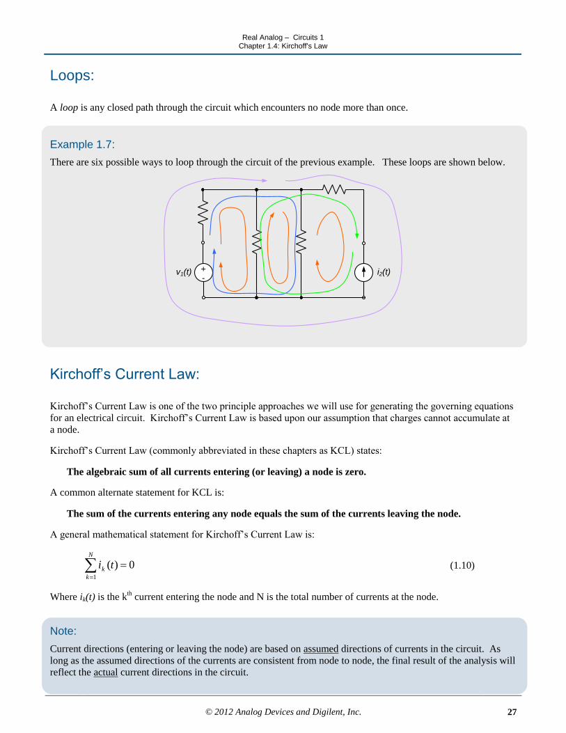
Loops:
A loop is any closed path through the circuit which encounters no node more than once.
Example 1.7:
There are six possible ways to loop through the circuit of the previous example. These loops are shown below.
+-
v1(t) i2(t)
Kirchoff’s Current Law:
Kirchoff’s Current Law is one of the two principle approaches we will use for generating the governing equations
for an electrical circuit. Kirchoff’s Current Law is based upon our assumption that charges cannot accumulate at
a node.
Kirchoff’s Current Law (commonly abbreviated in these chapters as KCL) states:
The algebraic sum of all currents entering (or leaving) a node is zero.
A common alternate statement for KCL is:
The sum of the currents entering any node equals the sum of the currents leaving the node.
A general mathematical statement for Kirchoff’s Current Law is:
N
k
k ti1
0)( (1.10)
Where ik(t) is the kth current entering the node and N is the total number of currents at the node.
Note:
Current directions (entering or leaving the node) are based on assumed directions of currents in the circuit. As
long as the assumed directions of the currents are consistent from node to node, the final result of the analysis will
reflect the actual current directions in the circuit.

Real Analog – Circuits 1 Chapter 1.4: Kirchoff's Law
© 2012 Analog Devices and Digilent, Inc.
28
Example 1.8:
In the figure below, the assumed directions of i1(t), i2(t) and i3(t) are as shown.
i1(t)i3(t)
i2(t)
If we (arbitrarily) choose a sign convention such that currents entering the node are positive then currents leaving
the node are negative and KCL applied at this node results in:
i1(t) + i2(t) - i3(t )= 0
If, on the other hand, we choose a sign convention that currents entering the node are negative, then currents
leaving the node are positive and KCL applied at this node results in:
-i1(t) - i2(t) + i3(t )= 0
These two equations are the same; the second equation is simply the negative of the first equation. Both of the
above equations are equivalent to the statement:
i1(t) + i2(t) = i3(t )

Real Analog – Circuits 1 Chapter 1.4: Kirchoff's Law
© 2012 Analog Devices and Digilent, Inc.
29
Example 1.9:
Use KCL to determine the value of the current i in the figure below.
-1A
i4A
2A
Summing the currents entering the node results in:
4A - (-1A) - 2A – i = 0 ⇒ i = 4A + 1A - 2A = 3A
and i = 3A, leaving the node.
In the figure below, we have reversed our assumed direction of i in the above circuit:
-1A
i4A
2A
Now, if we sum currents entering the node:
4A - (-1A) - 2A + i = 0 ⇒ i = -4A - 1A + 2A = -3A
so now i = -3A, entering the node. The negative sign corresponds to a change in direction, so we can interpret this
result to a +3A current leaving the node, which is consistent with our previous result. Thus, the assumed current
direction has not affected our results.
We can generalize Kirchoff’s Current Law to include any enclosed portion of a circuit. To illustrate this concept,
consider the portion of a larger circuit enclosed by a surface as shown in Figure 1.13 below. Since none of the
circuit elements within the surface store charge, the total charge which can be stored within any enclosed surface
is zero. Thus, the net charge entering an enclosed surface must be zero. This leads to a generalization of our
previous statement of KCL:
The algebraic sum of all currents entering (or leaving) any enclosed surface is zero.
Applying this statement to the circuit of Figure 1 results in:
i1 + i2 + i3 = 0

Real Analog – Circuits 1 Chapter 1.4: Kirchoff's Law
© 2012 Analog Devices and Digilent, Inc.
30
+
-
vs(t)
is(t)
i1
i2
i3
Figure 1.13 KCL applied to closed surface.
Kirchoff’s Voltage Law:
Kirchoff’s Voltage Law is the second of two principle approaches we will use for generating the governing
equations for an electrical circuit. Kirchoff’s Voltage Law is based upon the observation that the voltage at a
node is unique.
Kirchoff’s Voltage Law (commonly abbreviated in these chapters as KVL) states:
The algebraic sum of all voltage differences around any closed loop is zero.
An alternate statement of this law is:
The sum of the voltage rises around a closed loop must equal the sum of the voltage drops around the
loop.
A general mathematical statement for Kirchoff’s Voltage Law is:
N
k
k tv1
0)( (1.11)
Where vk(t) is the kth voltage difference in the loop and N is the total number of voltage differences in the loop.
Note:
Voltage polarities are based on assumed polarities of the voltage differences in the loop. As long as the assumed
directions of the voltages are consistent from loop to loop, the final result of the analysis will reflect the actual
voltage polarities in the circuit.
Example 1.10:
In the figure below, the assumed (or previously known) polarities of the voltages v1, v2, v3, v4, v5, and v6 are as
shown. There are three possible loops in the circuit: a-b-e-d-a, a-b-c-e-d-a, and b-c-e-b. We will apply KVL to
each of these loops.

Real Analog – Circuits 1 Chapter 1.4: Kirchoff's Law
© 2012 Analog Devices and Digilent, Inc.
31
Our sign convention for applying signs to the voltage polarities in our KVL equations will be as follows: when
traversing the loop, if the positive terminal of a voltage difference is encountered before the negative terminal, the
voltage difference will be interpreted as positive in the KVL equation. If the negative terminal is encountered
first, the voltage difference will be interpreted as negative in the KVL equation. We use this sign convention for
convenience; it is not required for proper application of KVL, as long as the signs on the voltage differences are
treated consistently.
+ -v1 +- v2
+ -v6
+
-
v3
+
-
v4
+
-
v5
a b c
d e
Applying KVL to the loop a-b-e-d-a, and using our sign convention as above results in:
v1 – v4 – v6 – v3 = 0
The starting point of the loop and the direction that we loop in is arbitrary; we could equivalently write the same
loop equation as loop d-e-b-a-d, in which case our equation would become:
v6 + v4 – v1 + v3 = 0
This equation is identical to the previous equation, the only difference is that the signs of all variables has
changed and the variables appear in a different order in the equation.
We now apply KVL to the loop b-c-e-b, which results in:
-v2 + v5 + v4 = 0
Finally, application of KVL to the loop a-b-c-e-d-a provides:
v1 – v2 + v5 – v6 – v3 = 0

Real Analog – Circuits 1 Chapter 1.4: Kirchoff's Law
© 2012 Analog Devices and Digilent, Inc.
32
Application Examples: Solving for Circuit Element Variables
Typically, when analyzing a circuit, we will need to determine voltages and/or currents in one or more elements in
the circuit. In this chapter, we discuss use of the tools presented in previous chapters for circuit analysis.
The complete solution of a circuit consists of determining the voltages and currents for every element in the
circuit. A complete solution of a circuit can be obtained by:
1. Writing a voltage-current relationship for each element in the circuit (e.g. write Ohm’s law for the
resistors)
2. Applying KCL at all but one of the nodes in the circuit
3. Applying KVL for all but one of the loops in the circuit
This approach will typically result in a set of N equations in N unknowns, the unknowns consisting of the
voltages and currents for each element in the circuit. Methods exist for defining a reduced set of equations for a
complete analysis of a circuit; these approaches will be presented in later chapters.
If KCL is written for every node in the circuit and KVL written for every loop in the circuit, the resulting set of
equations will typically be overdetermined and the resulting equations will, in general, not be independent. That
is, there will be more than N equations in N unknowns and some of the equations will carry redundant
information.
Generally, we do not need to determine all the variables in the circuit. This often means that we can write fewer
equations than those listed above. The equations to be written will, in these cases, be problem dependent and are
often at the discretion of the person doing the analysis.
Examples of using Ohm’s law, KVL, and KCL for circuit analysis are provided below.
Real Analog – Circuits 1 Chapter 1.4: Kirchoff's Law
© 2012 Analog Devices and Digilent, Inc.
33
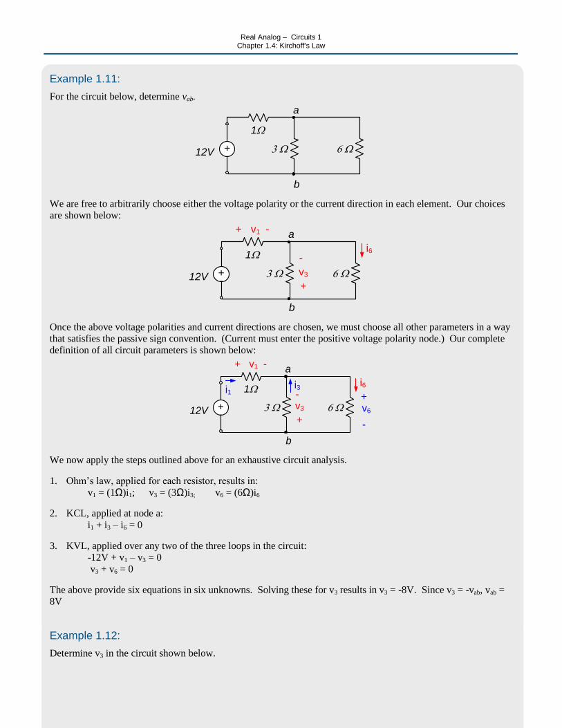
Example 1.11:
For the circuit below, determine vab.
+-12V
1W
3 W 6 W
a
b
We are free to arbitrarily choose either the voltage polarity or the current direction in each element. Our choices
are shown below:
+-12V
1W
3 W 6 W
a
b
i6
+
-
v3
+ -v1
Once the above voltage polarities and current directions are chosen, we must choose all other parameters in a way
that satisfies the passive sign convention. (Current must enter the positive voltage polarity node.) Our complete
definition of all circuit parameters is shown below:
+-12V
1W
3 W 6 W
a
b
i6
+
-v3
+ -v1
i1i3
+
-
v6
We now apply the steps outlined above for an exhaustive circuit analysis.
1. Ohm’s law, applied for each resistor, results in:
v1 = (1Ω)i1; v3 = (3Ω)i3; v6 = (6Ω)i6
2. KCL, applied at node a:
i1 + i3 – i6 = 0
3. KVL, applied over any two of the three loops in the circuit:
-12V + v1 – v3 = 0
v3 + v6 = 0
The above provide six equations in six unknowns. Solving these for v3 results in v3 = -8V. Since v3 = -vab, vab =
8V
Example 1.12:
Determine v3 in the circuit shown below.

Real Analog – Circuits 1 Chapter 1.4: Kirchoff's Law
© 2012 Analog Devices and Digilent, Inc.
34
2 A
2 W
3 W
+
-
v3
We choose voltages and currents as shown below. Since v3 is defined in the problem statement, we define it to be
consistent with the problem statement.
2 A
2 W
3 W
+
-
v3
a
b
i3
+
-
v2
i2
KVL around the single loop in the circuit does not help us – the voltage across the current source is unknown, so
inclusion of this parameter in a KVL equation simply introduces an additional unknown to go with the equation
we write. KVL would, however, be useful if we wished to determine the voltage across the current source.
KCL at node a tells us that i2 = 2A. Likewise, KCL at node b tells us that i2 – i3 = 0, so i3 = i2 = 2A. Ohms law
tells us that v3 = (3Ω)(i3) = (3Ω)(2A) = 6V.

Real Analog – Circuits 1 Chapter 1.4: Kirchoff's Law
© 2012 Analog Devices and Digilent, Inc.
35
Section Summary:
Kirchoff’s Current Law (KCL) and Kirchoff’s Voltage Law (KVL) govern the interactions between circuit
elements. Governing equations for a circuit are created by applying KVL and KCL and applying the circuit
element governing equations, such as Ohm’s Law.
Kirchoff’s current law states that the sum of the currents entering or leaving a node must be zero. A node in a
circuit is an point which has a unique voltage.
a. A node is a point of interconnection between two or more circuit elements. A circuit node has a particular
voltage. Nodes can be ―spread out‖ with perfect conductors.
Kirchoff’s voltage law states that the sum of the voltage differences around any closed loop in a circuit must
sum to zero. A loop in a circuit is any path which ends at the same point at which it starts.
a. A loop is a closed path through a circuit. Loops end at the same node at which they start, and typically
are chosen so that no node is encountered more than once.
Exercises:
1. For the circuit below, determine:
a) The current through the 2Ω resistor
b) The current through the 1Ω resistor
c) The power (absorbed or generated) by the 4V power source
+
-4V 2W1W