reading construction drawing
TRANSCRIPT

8/8/2019 Reading Construction Drawing
http://slidepdf.com/reader/full/reading-construction-drawing 1/7
1.1 INTRODUCTIONConstruction drawings are necessary in most spheresof the building industry, as being the best means of conveying detailed and often complex informationfrom the designer to all those concerned with the job.Building tradespeople, especially carpenters and join-ers, should be familiar with the basic principlesinvolved in understanding and reading drawings cor-rectly. Mistakes on either side – in design or interpret-ation of the design – can be costly, as drawings form alegal part of the contract between architect/client andbuilder.This applies even on small jobs, where only goodwill may suffer; for this reason, if a non-contractualdrawing or sketch is supplied, it should be kept for a
period of time after completion of the job, in case any queries should arise.
1.1.1 Retention of Drawings orSketchesA simple sketch supplied by a client in good faith to abuilder or joinery shop for the production of a replace-ment casement-type window, is shown in Figure 1.1(a). The client’s mistake in measuring between plasteredreveals is illustrated in Figure 1.1(b). Retention of thesketch protects the firm from the possibility of theclient’s wrongful accusation.
Another important rule is to study the whole draw-ing carefully and be reasonably familiar with thedetails before starting work.
The details given in this chapter are based on therecommendations laid down by the British Standards
Institution, in their latest available publications entitledConstruction drawing practice , BS 1192: Part 1: 1984,and BS 1192: Part 3: 1987. BS 1192: Part 5: 1990, which is not referred to here, is a guide for the structur-ing of computer graphic information.
1
Reading ConstructionDrawings
(a)
950
3 0 0
1 1 0 0
F
950
(b)
Figure 1.1 (a) Client’s sketch drawing(b) Horizontal section showing client’smistake
CH001 12/18/06 10:31 AM Page 1
8/8/2019 Reading Construction Drawing
http://slidepdf.com/reader/full/reading-construction-drawing 2/7
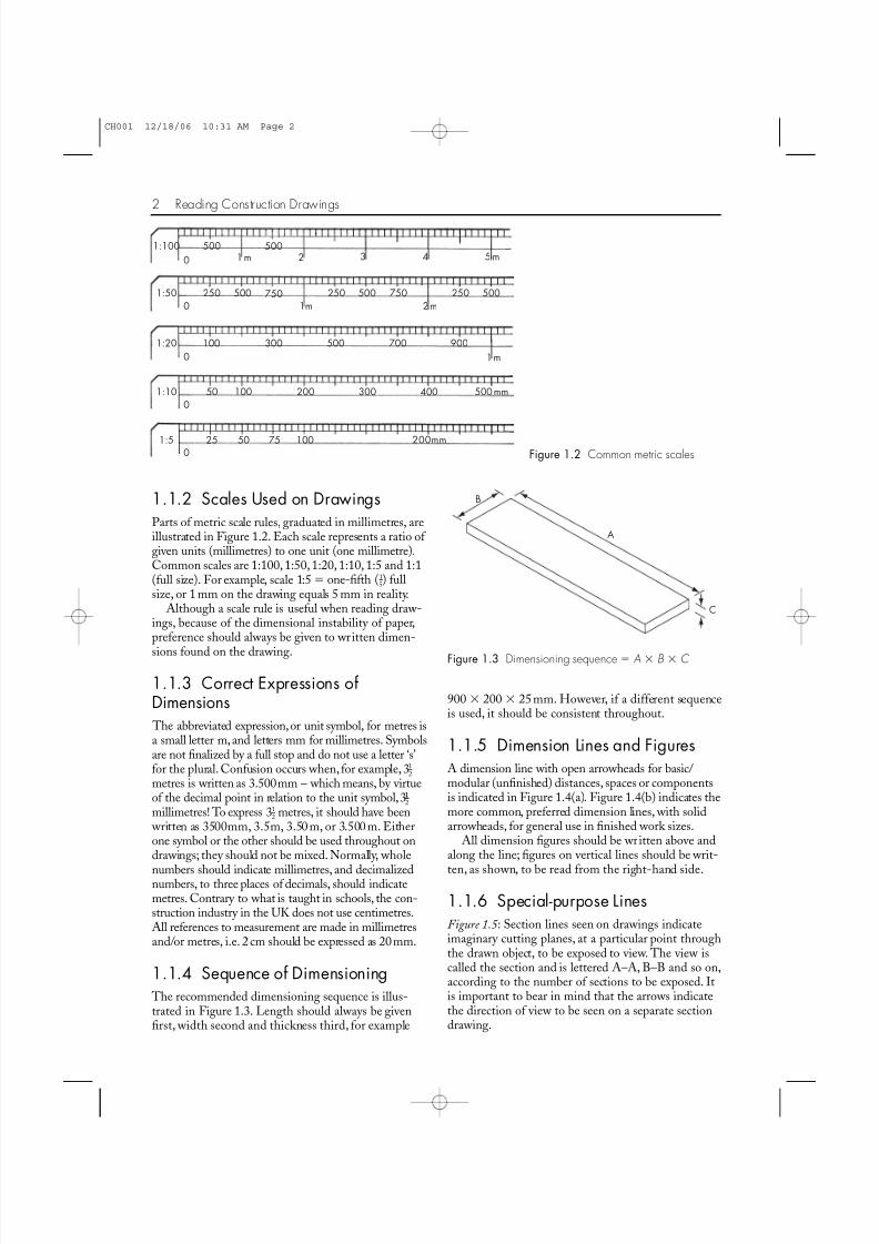
1.1.2 Scales Used on DrawingsParts of metric scale rules, graduated in millimetres, areillustrated in Figure 1.2. Each scale represents a ratio of given units (millimetres) to one unit (one millimetre).Common scales are 1:100, 1:50, 1:20, 1:10, 1:5 and 1:1(full size). For example, scale 1:5 one-fifth (1-5) fullsize, or 1 mm on the drawing equals 5 mm in reality.
Although a scale rule is useful when reading draw-ings, because of the dimensional instability of paper,preference should always be given to written dimen-
sions found on the drawing.
1.1.3 Correct Expressions ofDimensions The abbreviated expression,or unit symbol, for metres isa small letter m,and letters mm for millimetres. Symbolsare not finalized by a full stop and do not use a letter ‘s’for the plural. Confusion occurs when,for example, 31-2metres is written as 3.500mm – which means, by virtueof the decimal point in relation to the unit symbol,31-1-2millimetres! To express 31-2 metres, it should have been written as 3500mm, 3.5m, 3.50 m, or 3.500 m. Eitherone symbol or the other should be used throughout ondrawings; they should not be mixed. Normally, whole
numbers should indicate millimetres, and decimalizednumbers, to three places of decimals, should indicatemetres. Contrary to what is taught in schools, the con-struction industry in the UK does not use centimetres.All references to measurement are made in millimetresand/or metres, i.e. 2 cm should be expressed as 20mm.
1.1.4 Sequence of Dimensioning The recommended dimensioning sequence is illus-trated in Figure 1.3. Length should always be givenfirst, width second and thickness third, for example
900 200 25mm. However, if a different sequenceis used, it should be consistent throughout.
1.1.5 Dimension Lines and FiguresA dimension line with open arrowheads for basic/modular (unfinished) distances, spaces or componentsis indicated in Figure 1.4(a). Figure 1.4(b) indicates themore common, preferred dimension lines, with solidarrowheads, for general use in finished work sizes.
All dimension figures should be written above andalong the line; figures on vertical lines should be writ-
ten, as shown, to be read from the right-hand side.
1.1.6 Special-purpose LinesFigure 1.5 : Section lines seen on drawings indicateimaginary cutting planes, at a particular point throughthe drawn object, to be exposed to view. The view iscalled the section and is lettered A–A, B–B and so on,according to the number of sections to be exposed. Itis important to bear in mind that the arrows indicatethe direction of view to be seen on a separate sectiondrawing.
2 Reading Construction Drawings
1:100
1:50
1:20
1:10
1:5
0
0
0
0
0
2 3 4 5m1m
1m
1m
2m
500 500
250 500
25 50
50 100
75 100
200
200mm
300 400 500mm
750
100 300 500 700 900
250 500 750 250 500
Figure 1.2 Common metric scales
A
B
C
Figure 1.3 Dimensioning sequence A B C
CH001 12/18/06 10:31 AM Page 2

8/8/2019 Reading Construction Drawing
http://slidepdf.com/reader/full/reading-construction-drawing 3/7
Orthographic Projection 3
323 300
2 0 0
(a) (b)
Figure 1.4 Dimension lines(a) Open arrow-head (unfinished)(b) Solid arrow-head (finished)
C
C
D
D
A A
B B
E
E
Staggered section Vertical sectionsHorizontal sections Figure 1.5 Section lines
Figure 1.6 Hidden detail or work to beremoved
1.300
(b)(a) Figure 1.7 Break lines
Figure 1.8 Centre or axial line
Figure 1.6: Hidden detail or work to be removed, isindicated by a broken line.
Figure 1.7(a): End break-lines (zig-zag pattern) indi-cate that the object is not fully drawn.
Figure 1.7(b): Central break-lines (zig-zag pattern)indicate that the object is not drawn to scale in length.
Figure 1.8 : Centre or axial lines are indicated by a thindot-dash chain.
1.2 ORTHOGRAPHICPROJECTION
1.2.1 Introduction
Orthography is a Latin/Greek-derived word meaning‘correct spelling’ or ‘writing’. In technical drawing it isused to mean ‘correct drawing’; orthographic projec-tion, therefore, refers to a conventional drawingmethod used to display the three-dimensional views(length, width and height) of objects or arrangementsas they will be seen on one plane – namely the draw-ing surface.
The recommended methods are known as first-angle (or European) projection for construction draw-ings, and third-angle (or American) projection forengineering drawings.
1.2.2 First-angle Projection The box in Figure 1.9(a) is used here as a means of explaining first-angle projection (F.A.P.). If you canimagine the object shown in Figure 1.9(b) to be sus-pended in the box, with enough room left for you to walk around it, then by looking squarely at the objectfrom all sides and from above, the views seen would bethe ones shown on the surfaces in the background.
1.2.3 Opening the Topless BoxIn Figure 1.9(c) the topless box is opened out to givethe views as you saw them in the box and as they should be laid out on a drawing. Figure 1.9(d) showsthe BS symbol recommended for display on drawingsto indicate that first-angle projection (F.A.P.) has beenused.
Note that when views are separated onto differentdrawings, becoming unrelated orthographically,descriptive captions should be used such as ‘plan’,‘front elevation’, ‘side elevation’, etc.
CH001 12/18/06 10:31 AM Page 3

8/8/2019 Reading Construction Drawing
http://slidepdf.com/reader/full/reading-construction-drawing 4/7
4 Reading Construction Drawings
Vertical planes
FE FE
SE
SE.R/H RE SE.L/H
SE.L/H
Plan Plan
Horizontal plane
RE
Figure 1.9 (a) Theory of first-angle orthographicprojection (SE side elevation, FE front elevation,RE rear elevation, R/H right-hand side, L/H left-
hand side)
Front Side
Figure 1.9 (b) Example object
Side elevation R/H
Horizontal plane
Vertical planes
Plan
Front elevation Side elevation L/H Rear elevation
Figure 1.9 (c) First-angle projection
Figure 1.9 (d) F.A.P. symbol
Side e levation L/H Front elevation
Plan
Horizontal plane
Vertical planes
Side e levat ion R/H Rear e levat ion
Figure 1.9 (e) Third-angle projection
CH001 12/18/06 10:31 AM Page 4
8/8/2019 Reading Construction Drawing
http://slidepdf.com/reader/full/reading-construction-drawing 5/7
1.2.4 Third-angle Projection This is shown in Figure 1.9(e) for comparison only. Thistime the box has a top instead of a bottom; the viewsfrom the front and rear would be shown on the surfacein the background, as before,but the views seen on the
sides would be turned around and seen on the surfaces inthe foreground; the view from above (plan) would beturned and seen on the surface above.Figure 1.9(f)shows the BS symbol for third-angle projection (T.A.P.).
1.2.5 Pictorial ProjectionsFigure 1.10 : Another form of orthographic projectionproduces what is known as pictorial projections, whichpreserve the three-dimensional view of the object.Such views have a limited value in the make-up of actual working drawings, but serve well graphically toillustrate technical notes and explanations.
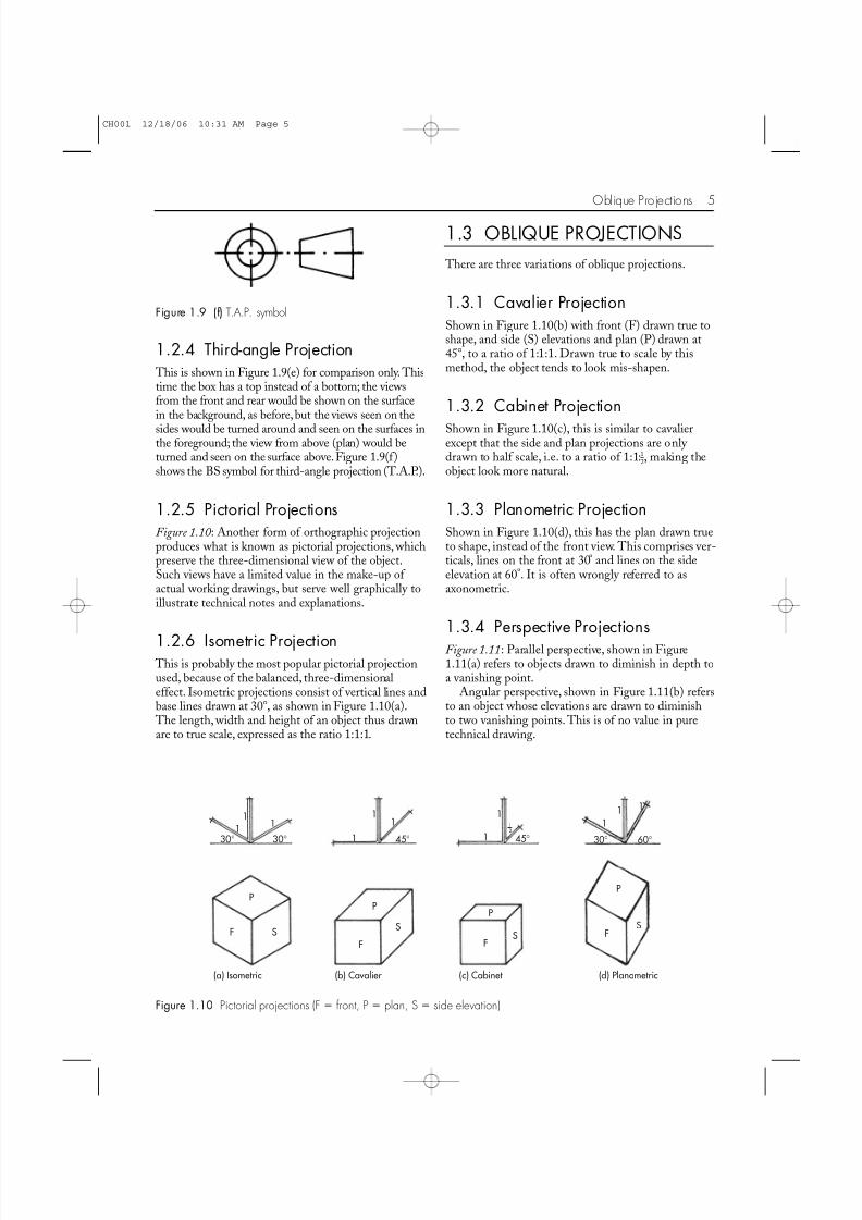
1.2.6 Isometric Projection This is probably the most popular pictorial projectionused, because of the balanced, three-dimensionaleffect. Isometric projections consist of vertical lines andbase lines drawn at 30, as shown in Figure 1.10(a). The length, width and height of an object thus drawnare to true scale, expressed as the ratio 1:1:1.
1.3 OBLIQUE PROJECTIONS
There are three variations of oblique projections.
1.3.1 Cavalier ProjectionShown in Figure 1.10(b) with front (F) drawn true toshape, and side (S) elevations and plan (P) drawn at45, to a ratio of 1:1:1. Drawn true to scale by thismethod, the object tends to look mis-shapen.
1.3.2 Cabinet Projection
Shown in Figure 1.10(c), this is similar to cavalierexcept that the side and plan projections are only drawn to half scale, i.e. to a ratio of 1:1:1-2, making theobject look more natural.
1.3.3 Planometric ProjectionShown in Figure 1.10(d), this has the plan drawn trueto shape, instead of the front view. This comprises ver-ticals, lines on the front at 30º and lines on the sideelevation at 60º. It is often wrongly referred to asaxonometric.
1.3.4 Perspective ProjectionsFigure 1.11: Parallel perspective, shown in Figure1.11(a) refers to objects drawn to diminish in depth toa vanishing point.
Angular perspective, shown in Figure 1.11(b) refersto an object whose elevations are drawn to diminishto two vanishing points. This is of no value in puretechnical drawing.
Oblique Projections 5
Figure 1.9 (f) T.A.P. symbol
11
11
1
11
1 11
PP
P
P
FF F
FS SS
S
1
30° 45° 45° 30° 60°30°
12
(a) Isometric (b) Cavalier (c) Cabinet (d) Planometric
Figure 1.10 Pictorial projections (F front, P plan, S side elevation)
CH001 12/18/06 10:31 AM Page 5

8/8/2019 Reading Construction Drawing
http://slidepdf.com/reader/full/reading-construction-drawing 6/7
1.3.5 Graphical Symbols andRepresentationFigure 1.12: Illustrated here are a selection of graph-ical symbols and representations used on buildingdrawings.Figure 1.13: On more detailed drawings, variousmaterials and elements are identified by such sectionalrepresentation as shown here.
To help reduce the amount of written informationon working drawings, abbreviations are often used. Aselection are shown here:BMA bronze metal antiqueDPC damp-proof courseDPM damp-proof membrane
EML expanded metal lathingpar planed all roundPVA polyvinyl acetate T&G tongue and groovebdg boarding
bldg buildingcpd cupboardhbd hardboardhwd hardwoodms mild steelswd softwood
1.3.6 Window IndicationFigure 1.14 : Windows shown on elevational drawingsusually display indications as to whether a window isfixed (meaning without any opening window or vent)
6 Reading Construction Drawings
VP VP
(a) Parallel perspective (b) Angular perspective
VP
Figure 1.11 Perspective projections (VP vanishing point)
dia (or ∅)
c/c
ffl
1 2 3 4 5 6 7 8 9= Rise of stair
= Finished floor level
= Centre to centre
= Diameter CL
GL
= Rise of ramp
= Ground level
= North point
= Centre line
1:10
Figure 1.12 Graphical symbols and representations
Brickwork
Concrete
Subsoil Insulation Screed/plaster/render
Hardcore Plywood Wood (sawn)
Wood (planed)
Topsoil Blockwork Stone
Figure 1.13 Sectional representation of materials
Horizontalpivot
W8 W7
W9
W6 W5 W4 W3
W2
W1
Verticalpivot
Sliding
Tilt and turn
Sliding Bottom hung Side hungFixing
Top hung
Figure 1.14 Opening/fixed window indication – numbered clockwise round the exterior of the building
CH001 12/18/06 10:31 AM Page 6

8/8/2019 Reading Construction Drawing
http://slidepdf.com/reader/full/reading-construction-drawing 7/7
or opening (meaning that the window is to open in aparticular way, according to the BS indication drawnon the glass area).
1.3.7 Door IndicationFigures 1.15 and 1.16: Doors shown on plan-view drawings are usually shown as a single line with anarrowed arc indicating their opening-direction, asillustrated. Alternatively, the 90 arrowed arc may bereplaced by a 45 diagonal line, from the door-jamb’sedge to the door’s leading edge. Figure 1.16 is theindication for revolving doors.
1.3.8 Block PlansFigure 1.17 : Block plans shown on construction draw-ings, usually taken from Ordinance Survey maps, are to
identify the site (e.g. No. 1 Woodman Road, as illus-trated) and to locate the outline of the building inrelation to its surroundings.
1.3.9 Site PlansFigure 1.18 : Site plans locate the position of buildingsin relation to setting-out points, means of access, andthe general layout of the site; they also give informa-tion on services and drainage, etc.
Oblique Projections 7
Sliding door Single swing
Single doordouble swing
Double doorssingle swing
Double doorsdouble swing
Figure 1.15 Plan view of door indication
Figure 1.16 Revolving doors
1 3 1113 15
14
4 7
4 5
W O O D MAN
R O A D
R O AD
L O F T S
Figure 1.17 Block plan (scale 1:1250)
MH3
SVP GG
G
8 . 7
5 0No. 1
WOODMANROAD
5 . 6
0 0
6.250
1.500
MH2
MH1
Figure 1.18 Site plan (scale 1:200)
1.3.10 Location Drawings These are usually drawn to a scale of 1:50 and are usedto portray the basic, general construction of buildings.Other, more detailed, drawings cover all other aspects.
CH001 12/18/06 10:31 AM Page 7