read this owner’s manual replacements are available from ... manuals/thern 477 series...
TRANSCRIPT
Read this Owner’s Manual thoroughly before operating the equipment. Keep it with the equipment at all times. Replacements are available from Thern, Inc., PO Box 347, Winona, MN 55987, 507-454-2996.www.thern.com
IMPORTANT: Please record product information on page 2. This information is required when calling the factory for service.
A5445I-0915
Owner’s ManualFor 477 SeriesHelical/Worm Gear Power Winches

Owner's Manual for Thern 477 Series Power Winchespage 2
A5445I-0915
Two-Year Limited WarrantyThern, Inc. warrants its products against defects in material or workmanship for two years from the date of purchase by the original using buyer, or if this date cannot be established, the date the product was sold by Thern, Inc. to the dealer. To make a claim under this warranty, contact the factory for an RGA number. The product must be returned, prepaid, directly to Thern, Inc., 5712 Industrial Park Road, Winona, Minnesota 55987. The following information must accompany the product: the RGA number, the date of purchase, the description of the claimed defect, and a complete explanation of the circumstances involved. If the product is found to be defective, it will be repaired or replaced free of charge, and Thern, Inc. will reimburse the shipping cost within the contiguous USA.
This warranty does not cover any damage due to accident, misuse, abuse, or negligence. Any alteration, repair or modification of the product outside the Thern, Inc. factory shall void this warranty. This warranty does not cover any costs for removal of our product, downtime, or any other incidental or consequential costs or damages resulting from the claimed defects. This warranty does not cover brake discs, wire rope or other wear components, as their life is subject to use conditions which vary between applications.
FACTORY AUTHORIZED REPAIR OR REPLACEMENT AS PROVIDED UNDER THIS WARRANTY IS THE EXCLUSIVE REMEDY TO THE CONSUMER. THERN, INC. SHALL NOT BE LIABLE FOR ANY INCIDENTAL OR CONSEQUENTIAL DAMAGES FOR BREACH OF ANY EXPRESS OR IMPLIED WARRANTY ON THIS PRODUCT. EXCEPT TO THE EXTENT PROHIBITED BY APPLICABLE LAW, ANY IMPLIED WARRANTY OF MERCHANTABILITY OR FITNESS FOR A PARTICULAR PURPOSE ON THIS PRODUCT IS LIMITED IN DURATION TO THE DURATION OF THIS WARRANTY.
Some states do not allow the exclusion or limitation of incidental or consequential damages, or allow limitations on how long an implied warranty lasts, so the above limitation or exclusion may not apply to you. This warranty gives you specific legal rights, and you may also have other rights which vary from state to state.
Note: Thern, Inc. reserves the right to change the design or discontinue the production of any product without prior notice.
About This ManualThe Occupational Safety and Health Act of 1970 states that it is the employer’s responsibility to provide a workplace free of hazard. To this end, all equipment should be installed, operated, and maintained in compliance with applicable trade, industrial, federal, state, and local regulations. It is the equipment owner's responsibility to obtain copies of these regulations and to determine the suitability of the equipment to its intended use.
This Owner’s Manual, and warning labels attached to the equipment, are to serve as guidelines for hazard-free installation, operation, and maintenance. They should not be understood to prepare you for every possible situation.
Information contained in this Owner's Manual is applicable only to the Thern 477 Series Power Winches. Do not use this manual as a source of information for any other equipment.
The following symbols are used for emphasis throughout this manual:
Please record the following:Date Purchased:
Model No.:
Serial No.:
This information is required when calling the factory for service.
Failure to follow ‘WARNING!’ instructions may result in equipment damage, property damage, and/or serious personal injury.
Failure to follow ‘CAUTION!’ instructions may result in equipment damage, property damage, and/or minor personal injury.
Important!
Failure to follow ‘important!’ instructions may result in poor performance of the equipment.
Owner's Manual for Thern 477 Series Power Winches page 3
A5445I-0915
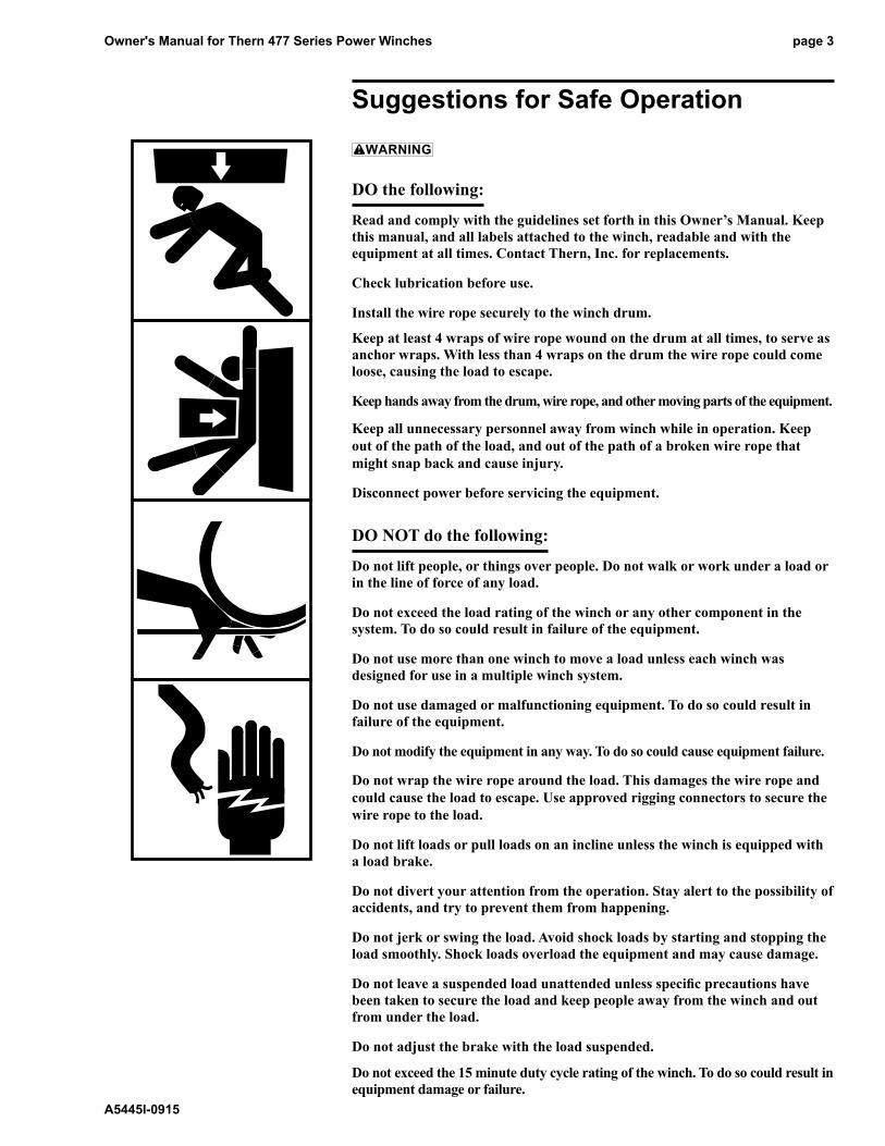
Suggestions for Safe Operation
DO the following:
Read and comply with the guidelines set forth in this Owner’s Manual. Keep this manual, and all labels attached to the winch, readable and with the equipment at all times. Contact Thern, Inc. for replacements.
Check lubrication before use.
Install the wire rope securely to the winch drum.
Keep at least 4 wraps of wire rope wound on the drum at all times, to serve as anchor wraps. With less than 4 wraps on the drum the wire rope could come loose, causing the load to escape.
Keep hands away from the drum, wire rope, and other moving parts of the equipment.
Keep all unnecessary personnel away from winch while in operation. Keep out of the path of the load, and out of the path of a broken wire rope that might snap back and cause injury.
Disconnect power before servicing the equipment.
DO NOT do the following:
Do not lift people, or things over people. Do not walk or work under a load or in the line of force of any load.
Do not exceed the load rating of the winch or any other component in the system. To do so could result in failure of the equipment.
Do not use more than one winch to move a load unless each winch was designed for use in a multiple winch system.
Do not use damaged or malfunctioning equipment. To do so could result in failure of the equipment.
Do not modify the equipment in any way. To do so could cause equipment failure.
Do not wrap the wire rope around the load. This damages the wire rope and could cause the load to escape. Use approved rigging connectors to secure the wire rope to the load.
Do not lift loads or pull loads on an incline unless the winch is equipped with a load brake.
Do not divert your attention from the operation. Stay alert to the possibility of accidents, and try to prevent them from happening.
Do not jerk or swing the load. Avoid shock loads by starting and stopping the load smoothly. Shock loads overload the equipment and may cause damage.
Do not leave a suspended load unattended unless specific precautions have been taken to secure the load and keep people away from the winch and out from under the load.
Do not adjust the brake with the load suspended.
Do not exceed the 15 minute duty cycle rating of the winch. To do so could result in equipment damage or failure.

Owner's Manual for Thern 477 Series Power Winchespage 4
A5445I-0915
1.1 Installing the Winch
Do not install the winch in an area defined as hazardous by the National Electric Code, unless installation in such an area has been thoroughly approved.
Do not install the winch near corrosive chemicals, flammable materials, explosives, or other elements that may damage the winch or injure the operator. Adequately protect the winch and the operator from such elements.
Position the winch so the operator can stand clear of the load, and out of the path of a broken wire rope that could snap back and cause injury.
Attach the winch to a rigid and level foundation that will support the winch and its load under all load conditions, including shock loading.
1.1.1 CONSULT APPLICABLE CODES AND REGULATIONS for specific rules on installing the equipment.
1.1.2 LOCATE THE WINCH in an area clear of traffic and obstacles. Make sure the winch is accessible for maintenance and operation.
1.1.3 LOCATE THE WINCH in an area with adequate temperatures. The winch is rated for operation in ambient temperatures ranging from 0° to 100° F.
1.1.4 MAINTAIN A FLEET ANGLE between 1/2 and 1-1/2 degrees. The proper fleet angle minimizes wire rope damage by helping the wire rope wind uniformly onto the drum. See Figure 2.
1.1.5 POSITION THE WINCH to allow access for proper lubrication.
1.1.6 DETERMINE THE CORRECT MOUNTING POSITION of the winch. Some models can only be floor mounted. See page 23 Motor Adapter Assembly, footnote 2.
1.1.7 FASTEN THE WINCH securely to the foundation.
a FOR STANDARD PRODUCTS referred to in this manual, use 5/16 inch coarse thread fasteners, grade 5 or better, torque dry to 17 ft. lb. without lubrication. Make sure the winch is secured to a solid foundation able to support the winch and the load under all conditions with design factors based on accepted engineering practices.
b NON-STANDARD PRODUCTS that vary from the original design may have different fastening requirements. Contact a structural engineer or Thern, Inc. for this information.
TO COMPLY WITH LOCAL CODES, CONTACT A QUALIFIED PROFESSIONAL TO OBTAIN PROPER STRUCTURE OR FOUNDATION SPECIFICATIONS FOR THE MOUNTING OF THERN PRODUCTS.
Important!
• Inspect the winch immediately following installation according to the Instructions for Periodic Inspection. This will give you a record of the condition of the winch with which to compare future inspections.
• A qualified professional should inspect or design the foundation to insure that it will provide adequate support.
• Locate the winch so it will be visible during the entire operation.
• Do not weld the winch frame to the foundation or support structure. Welding the frame may void warranty, contact Thern, Inc. Use fasteners as instructed.
Owner's Manual for Thern 477 Series Power Winches page 5
A5445I-0915
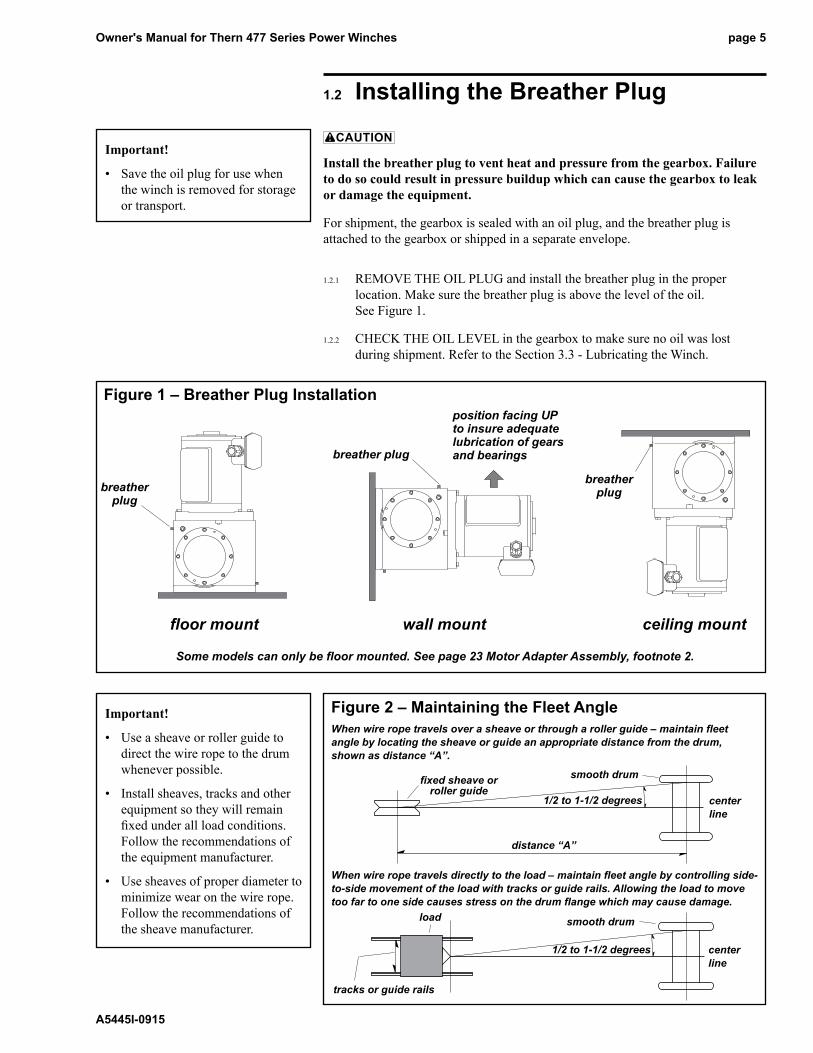
1.2 Installing the Breather Plug
Install the breather plug to vent heat and pressure from the gearbox. Failure to do so could result in pressure buildup which can cause the gearbox to leak or damage the equipment.
For shipment, the gearbox is sealed with an oil plug, and the breather plug is attached to the gearbox or shipped in a separate envelope.
1.2.1 REMOVE THE OIL PLUG and install the breather plug in the proper location. Make sure the breather plug is above the level of the oil. See Figure 1.
1.2.2 CHECk THE OIL LEVEL in the gearbox to make sure no oil was lost during shipment. Refer to the Section 3.3 - Lubricating the Winch.
smooth drum
1/2 to 1-1/2 degrees
distance “A”
center line
fixed sheave or roller guide
Important!
• Use a sheave or roller guide to direct the wire rope to the drum whenever possible.
• Install sheaves, tracks and other equipment so they will remain fixed under all load conditions. Follow the recommendations of the equipment manufacturer.
• Use sheaves of proper diameter to minimize wear on the wire rope. Follow the recommendations of the sheave manufacturer.
Figure 2 – Maintaining the Fleet AngleWhen wire rope travels over a sheave or through a roller guide – maintain fleet angle by locating the sheave or guide an appropriate distance from the drum, shown as distance “A”.
When wire rope travels directly to the load – maintain fleet angle by controlling side-to-side movement of the load with tracks or guide rails. Allowing the load to move too far to one side causes stress on the drum flange which may cause damage.
1/2 to 1-1/2 degrees center line
smooth drum
tracks or guide rails
load
Important!
• Save the oil plug for use when the winch is removed for storage or transport.
Figure 1 – Breather Plug Installation
breather plug
breather plug
position facing UP to insure adequate lubrication of gears and bearings
breather plug
floor mount wall mount ceiling mount
Some models can only be floor mounted. See page 23 Motor Adapter Assembly, footnote 2.
Owner's Manual for Thern 477 Series Power Winchespage 6
A5445I-0915
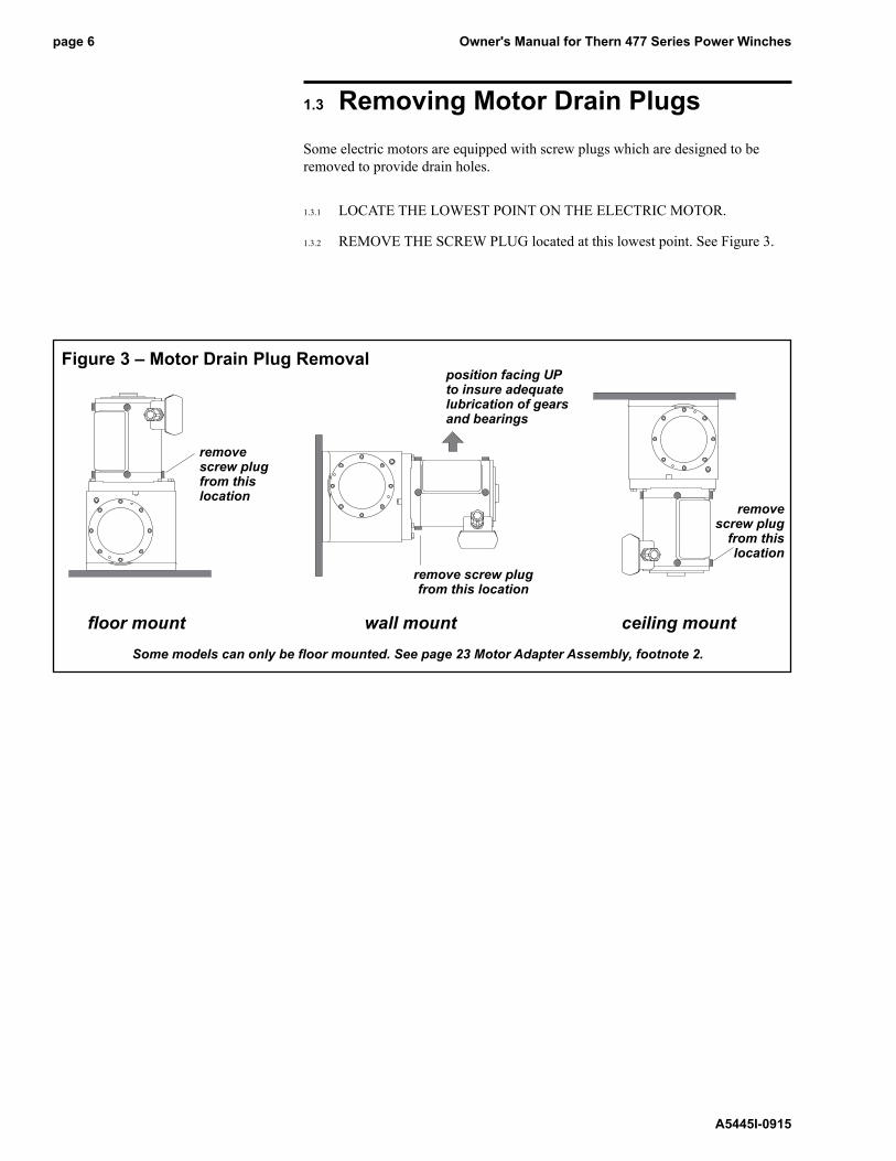
1.3 Removing Motor Drain PlugsSome electric motors are equipped with screw plugs which are designed to be removed to provide drain holes.
1.3.1 LOCATE THE LOWEST POINT ON THE ELECTRIC MOTOR.
1.3.2 REMOVE THE SCREW PLUG located at this lowest point. See Figure 3.
Figure 3 – Motor Drain Plug Removal
remove screw plug from this location
remove screw plug from this location
position facing UP to insure adequate lubrication of gears and bearings
floor mount wall mount ceiling mount
remove screw plug
from this location
Some models can only be floor mounted. See page 23 Motor Adapter Assembly, footnote 2.

Owner's Manual for Thern 477 Series Power Winches page 7
A5445I-0915
1.4 Connecting Electric Power
Install proper branch circuits, disconnect devices, protection, and grounding as required by article 430 of the National Electric Code.
All electrical work must be performed by a licensed electrician. Failure to do so could result in electric shock or poor winch operation.
All control devices must be momentary contact type. Install all control devices so the winch motor will stop when the operator releases the device.
Locate control devices so the operator will be able to view the load through the entire operation.
Locate control devices so the operator will be clear of the load, the wire rope, and the path of a broken wire rope that could snap back and cause injury.
It is the responsibility of the owner to provide equipment for controlling the winch. Controls are available from Thern. The following guidelines are supplied as a reference for the installer.
1.4.1 CONSULT APPLICABLE CODES AND REGULATIONS for specific instructions regarding power supply installation and hookup.
1.4.2 FOR ELECTRIC WINCHES: install a fuse or circuit breaker, and a disconnect device in the power supply circuit, as required by the National Electric Code. The disconnect device should be a switch you can lock in the off position to prevent unauthorized use of the winch.
1.4.3 CONNECT THE POWER CORD to a grounded outlet.
1.4.4 FOR PNEUMATIC WINCHES: install a regulator, filter, lubricator and drier in the air supply line. Failure to operate motor with clean, dry, lubricated air will void warranty.
1.4.5 FOR HYDRAULIC WINCHES: install a filter in the hydraulic supply line. Use Mobil DTE hydraulic fluid, or equal, with a viscosity range of 100 – 200 SUS.
1.4.6 INSTALL A CONTROL DEVICE in the power supply line and connect power to the motor. Make sure the control device is a momentary contact type so the motor will stop when the operator releases the control.
1.4.7 CONNECT OTHER EQUIPMENT to the power supply as necessary.
1.4.8 CHECk POWER SUPPLY at the motor and make sure it agrees with the motor rating. Do not operate the winch until proper power is supplied to the motor.
1.4.9 TEST CONNECTIONS by operating the winch. The rotation of the drum must agree with the labels on the control device, and the motor must stop when the control is released.
CONTACT THE FACTORY OR A QUALIFIED PROFESSIONAL FOR HELP.
Important!
• Use components rated for the power supply you will be using.
• Always disconnect power when the winch is not in use.

Owner's Manual for Thern 477 Series Power Winchespage 8
A5445I-0915
1.5 Installing the Wire Rope
Install the wire rope securely to the winch drum. A poorly secured wire rope could come loose from its anchor and allow the load to escape.
Install the wire rope so it is wound correctly as shown or the winch and brake will not work properly, and could allow the load to escape, see Figure 4.
Anchor fitting must clear the reducer frame when operating. Binding of the anchor fitting between the frame and flange could damage the equipment.
1.5.1 PURCHASE THE PROPER WIRE ROPE for your application. keep the following in mind when selecting a wire rope. Contact a reputable wire rope supplier for help.
a BREAkING STRENGTH of new wire rope should be at least 3 times greater than the largest load placed on the winch. If loads are lifted or pulled on an incline, the breaking strength must be at least 5 times greater than the largest load. These are minimum values and will vary with the type of load and how you are moving it.
b WIRE ROPE LAY must agree with the winding direction of the drum to help insure proper winding.
c WE RECOMMEND 7x19 galvanized aircraft cable for diameters up to 5/16 inch.
1.5.2 ANCHOR THE WIRE ROPE to the drum using either the set screw or quick disconnect anchor.
a SET SCREW ANCHOR. See Figure 4.
• PASS THE WIRE ROPE under the drum from the front and position it in the slot in the drum. Make sure at least 1/2 inch of wire rope extends past the set screw, and the end of the wire rope does not protrude out where it will interfere with wire rope winding onto the drum.
• TIGHTEN THE SET SCREW to hold the wire rope in place. Hold the wire rope down while tightening so the wire rope does not push up out of the slot.
b QUICk DISCONNECT ANCHOR. See Figure 4.
• PASS THE WIRE ROPE under the drum from the front and position the anchor fitting in the groove in the drum.
• PULL THE WIRE ROPE to firmly lodge the anchor fitting in place.
1.5.3 WIND FOUR FULL WRAPS of wire rope onto the drum by operating the winch while holding the wire rope taught. These wraps serve as anchor wraps and must remain on the drum at all times. See Figure 4.
CONTACT A REPUTABLE WIRE ROPE SUPPLIER FOR HELP.
Important!
• Use wire rope and other rigging equipment rated for the size of the largest load you will be moving.
• Do not drag the wire rope through dirt or debris that could cause damage, or poor operation.
• Always wear protective clothing when handling wire rope.
Figure 4 – Installing the Wire Rope
Wire rope assemblies with anchor fittings can be purchased from Thern, Inc.
anchor fitting installation
anchor fitting must clear frame and drum flange when operating.
install the wire rope
so it is underwound on the drum
as shown
set screw
recessed anchor installation

Owner's Manual for Thern 477 Series Power Winches page 9
A5445I-0915
2.1 General Theory of Operation2.1.1 THE FORCE REQUIRED to move the load must not exceed the load rating of
the winch. Consider the total force required to move the load, not the weight of the load.
2.1.2 THE AMOUNT OF TIME required to move the load must not exceed the 15 minute duty cycle rating of the winch. Allow the winch to cool between cycles.
2.1.3 EQUIPMENT CAN DEVELOP forces that will exceed the load rating. It is the responsibility of the equipment user to limit the size of the load. Inspect the equipment regularly for damage according to the instructions contained in this manual and in component manufacturer’s information.
2.1.4 USE A LOAD BRAkE on all winches used to lift loads or pull loads on an incline. Although a new winch may appear to hold the load in place, this characteristic will diminish with use. Do not depend on gearing to hold the load in place.
2.1.5 PERFORMANCE RATINGS of the equipment are affected by the amount of wire rope wound on the drum, the way in which it is wound, and the way the winch is used.
a DRUM CAPACITY depends on how tightly and evenly the wire rope is wound on the drum. Actual drum capacities are usually 25-30% less than values shown in performance tables, due to loose winding and overlapping.
b LINE SPEED increases with each additional layer of wire rope wound onto the drum. Line speed will also vary with load weight and power supply for pneumatic and hydraulic models. Load weight does not affect line speed for electric models.
c LOAD RATING represents the maximum force that can be placed on new equipment. Load ratings are assigned values for specific amounts of load travel or wire rope accumulation. The load rating decreases as layers of wire rope accumulate on the drum.
2.1.6 DUTY RATINGS refer to the type of use the equipment is subject to. Consider the following when determining duty rating. This winch has a 15 minute duty cycle rating.
a ENVIRONMENT: harsh environments include hot, cold, dirty, wet, corrosive, or explosive surroundings. Protect the equipment from harsh environments when possible.
b MAINTENANCE: poor maintenance, meaning poor cleaning, lubrication, or inspection, leads to poor operation and possible damage of the equipment. Minimize poor maintenance by carefully following the instructions contained in this manual.
c LOADING: severe loading includes shock loading and moving loads that exceed the load rating of the equipment. Avoid shock loads, and do not exceed the load rating of the equipment.
d FREQUENCY OF OPERATION: frequent or lengthy operations increase wear and shorten the life span of gears, bearings, and other components. Increase maintenance of the equipment if used in frequent operations. Length of operation should not exceed the 15 minute duty cycle rating.
CONTACT THE FACTORY FOR MORE INFORMATION.
Important!
• Limit nonuniform winding by keeping tension on the wire rope and by maintaining the proper fleet angle.
• To help insure rated performance, make sure voltage at the motor is equal to the motor’s voltage rating.
• It is your responsibility to detect and account for different factors affecting the condition and performance of the equipment.

Owner's Manual for Thern 477 Series Power Winchespage 10
A5445I-0915
2.2 Breaking-In the Winch2.2.1 BREAk-IN OCCURS during the first 30 to 60 minutes of operation. During
break-in, mating surfaces become polished, and clearances increase. This is desired for efficient operation of bearings and gears.
2.2.2 INSPECT THE WINCH following break-in according to the Instructions for Periodic Inspection. See section 3.4 - Inspecting the Equipment.
2.3 Preparing for Operation2.3.1 CONSIDER THE OPERATION. Do not begin until you are sure you can
perform the entire operation without hazard.
2.3.2 INSPECT ALL COMPONENTS of the system.
a INSPECT THE WINCH and other equipment according to the Instructions for Frequent Inspection.
b OPERATORS MUST be in good health, alert, thoroughly trained in operating the equipment, and properly clothed (hard hat, safety shoes and safety glasses, no loose clothing).
c LOAD MUST be clear of other objects and free to move. Make sure the load will not tip, spin, roll away, or in any way move uncontrollably.
2.3.3 kNOW YOUR LOAD and make sure you do not exceed the load rating of the winch or any other equipment in the system.
2.4 Attaching the Load
Do not wrap the wire rope around the load. This damages the wire rope and could cause the load to escape. Use a sling or other approved rigging device.
2.4.1 CLEAR OBjECTS from the path of the load so you can move it freely and observe it at all times during the operation.
2.4.2 ATTACH THE LOAD using a nylon sling, or other approved rigging device. Follow the recommendations of the sling manufacturer.
a SEAT THE SLING in the saddle of the hook with the hook latch completely closed. See Figure 5.
b CENTER THE LOAD on the hook so it will remain balanced and not tip or rotate to one side.
Important!
• When determining whether the load will exceed the load rating, consider the total force required to move the load.
Figure 5 – Attaching Load
latch closed tight against
hook
sling seated in saddle of hook

Owner's Manual for Thern 477 Series Power Winches page 11
A5445I-0915
2.5 Moving the Load2.5.1 MOVE THE LOAD slowly and smoothly, only a small distance at first.
Make sure the load is balanced and securely attached before continuing.
2.5.2 USE THE CONTROL DEVICE to operate the winch. The control device should be momentary contact type, so the winch will stop when the operator releases the control.
2.5.3 DO NOT EXCEED duty cycle rating of the winch. The equipment is rated for a 15 minute duty cycle.
2.5.4 OBSERVE THE WIRE ROPE as it winds onto the drum. If it becomes loose, uneven, or overlapped, stop the operation and rewind the wire rope before continuing. Continued operation with overlapped or uneven wire rope can damage the wire rope and shorten its life.
2.5.5 ALLOW THE WINCH TO COOL DOWN to ambient temperature in rest periods between operations.
2.5.6 OBSERVE THE GEARBOX AND BRAkE during operation for signs of overheating. Frequent overheating may be a sign of damage, or may indicate the need for a larger power winch.
a WATCH FOR SMOkE, the smell of burnt oil, and other signs of overheating. Use a thermocouple or other device to monitor gearbox temperature. The temperature of the oil should not exceed 180° F.
b STOP THE OPERATION if the gearbox or brake overheats, and allow the winch to cool until it reaches ambient temperature. Continued operation may cause damage.
Important!
• Obey a stop signal from anyone.
• Maintain tension on the wire rope to keep it tightly and evenly wound on the drum.
• If the winch and load are not visible during the entire operation, get help from another person.
• Appoint a supervisor if more than one person is involved in the operation. This will reduce confusion and increase safety.
• When lifting a load, use a tag line to keep the load from swinging or twisting, while keeping yourself away from the load.

Owner's Manual for Thern 477 Series Power Winchespage 12
A5445I-0915
2.6 Emergency Operation (for models equipped with this feature)
Do not adjust the brake with the load suspended. Accidental release of the brake could allow the load to escape.
Do not leave a suspended load unattended unless specific precautions have been taken to secure the load and keep unnecessary personnel away from the winch and from under the load.
2.6.1 IN CASE OF POWER FAILURE, turn the control device to OFF and DISCONNECT electric power. Leave electric power DISCONNECTED.
2.6.2 MAkE SURE SAFETY PRECAUTIONS have been taken to secure the load and keep unnecessary personnel away from the winch and from under the load while operating the emergency hand crank. Assign a person to observe and control the load.
2.6.3 IF EQUIPPED WITH A BRAkE MOTOR you must disengage the brake on the motor before using the emergency hand crank. Operating the emergency hand crank with the brake on the motor engaged could result in equipment damage or failure.
a IT IS RECOMMENDED to have more than one person operate the winch using the emergency hand crank.
b ASSIGN ONE PERSON to operate the hand crank while another is assigned to operate the brake. Have control of the hand crank before disengaging the brake on the motor. Accidental release of the brake could allow the load to escape.
c ALWAYS FOLLOW the brake manufacturers operating instructions for engaging or disengaging the brake.
2.6.4 DO NOT USE AN IMPACT WRENCH to operate the emergency hand crank option of the winch. To do so could result in equipment damage or failure. Use a drill-motor.
2.6.5 DO NOT EXCEED THE 15 MINUTE DUTY CYCLE rating of the winch if operating with a drill-motor and do not operate the winch with a drill-motor that exceeds 400 rpm. To do so could result in equipment damage or failure.
2.6.6 IF EQUIPPED WITH A BRAkE MOTOR you must engage the brake on the motor and remove the handle or drill-motor before operating the winch under power.
ANY QUESTIONS ON OPERATING THE EMERGENCY HAND CRANk OPTION OR WINCH APPLICATION CONTACT THERN, INC.
Owner's Manual for Thern 477 Series Power Winches page 13
A5445I-0915
3.1 Cleaning the Winch Clean the winch to remove dirt and help prevent rust and corrosion.
3.1.1 CLEAN THE WINCH every 6 months or whenever it is dirty.
a WIPE ALL EQUIPMENT to remove dirt and grease.
b LEAVE A LIGHT FILM of oil on all surfaces to protect them against rust and corrosion.
c WIPE OFF excessive amounts of oil to avoid the accumulation of dirt.
3.1.2 REMOVE ALL UNNECESSARY OBjECTS from the area surrounding the winch.
3.2 Adjusting the Brake
Do not adjust the brake with the load suspended. Accidental release of the brake could allow the load to escape.
3.2.1 ADjUST THE BRAkE whenever it appears to need adjustment, or at least every 3 months.
3.2.2 CHECk THE BRAkE by operating the winch with a test load equal to the winch load rating.
a RAISE THE LOAD, then lower it and stop it about one foot off the ground.
b OBSERVE THE LOAD when stopped. If it continues to coast or creep, the brake should be tightened.
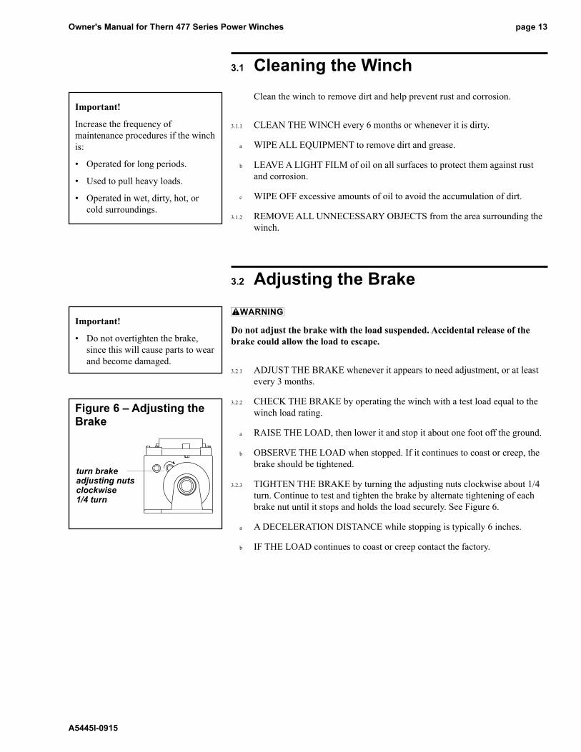
3.2.3 TIGHTEN THE BRAkE by turning the adjusting nuts clockwise about 1/4 turn. Continue to test and tighten the brake by alternate tightening of each brake nut until it stops and holds the load securely. See Figure 6.
a A DECELERATION DISTANCE while stopping is typically 6 inches.
b IF THE LOAD continues to coast or creep contact the factory.
Important!
Increase the frequency of maintenance procedures if the winch is:
• Operated for long periods.
• Used to pull heavy loads.
• Operated in wet, dirty, hot, or cold surroundings.
Important!
• Do not overtighten the brake, since this will cause parts to wear and become damaged.
Figure 6 – Adjusting the Brake
turn brake adjusting nuts clockwise 1/4 turn

Owner's Manual for Thern 477 Series Power Winchespage 14
A5445I-0915
Important!
• Do not leave plug holes in the reducer open. Open plug holes will allow dirt and moisture to contaminate the lubrication.
• Make sure lubricant has a temperature rating appropriate for the ambient temperatures of the operation.
3.3 Lubricating the Winch
Make sure the breather plug is clean and open to vent heat and pressure. Poor ventilation may cause overheating and result in equipment damage.
Check the gearbox for proper level before operating. Too much or too little oil will cause overheating and result in equipment damage.
Lubricate the winch properly to help protect it from wear and rust. Read the following instructions carefully.
3.3.1 FOR 477 SERIES, the winch is shipped from the factory with proper amount (92 ounces) of Mobilgear 600 XP220 lubricant in the gearbox. Lubricate the winch as follows. See Figure 7.
3.3.2 MOTOR BEARINGS are typically lubricated for life by the manufacturer.
a REPLACE MOTOR BEARINGS if the motor is disassembled for any reason.
b REFER TO MOTOR MANUFACTURER’S information for specific instructions regarding motor lubrication.
3.3.3 CHECk OIL LEVEL before every operation and every 10 hours during operation. Remove the level check plug and make sure oil is even with the plug hole. Add oil to the gearbox if necessary. Do not use synthetic lubricants and do not mix different lubricants. See Figure 7.
3.3.4 CHANGE GEARBOX OIL at least every 6 months, or whenever it is dirty or contaminated. Remove the drain plug to drain oil from the gearbox. See Figure 7.
3.3.5 LUBRICATE THE WIRE ROPE and other equipment by following the manufacturer's recommendations.
Figure 7 – Lubricating the Winch
filler plug
drain plug
position facing UP to insure adequate lubrication of gears and bearings
filler/level check plug
floor mount wall mount ceiling mount
level check plug
level check plug
drain plug
filler plug
drain plug
Some models can only be floor mounted. See page 23 Motor Adapter Assembly, footnote 2.

Owner's Manual for Thern 477 Series Power Winches page 15
A5445I-0915
3.4 Inspecting the Equipment
Do not use damaged or malfunctioning equipment. Place an “OUT OF ORDER” sign on the winch. Do not use the winch until the sign is removed by a qualified maintenance person who has completely corrected the problem.
Inspect the winch to detect signs of damage or poor operation before they become hazardous.
3.4.1 CONSULT APPLICABLE CODES AND REGULATIONS for specific rules on inspecting the winch and other equipment.
3.4.2 CONSULT MANUFACTURER’S RECOMMENDATIONS for information on inspecting the wire rope and other equipment.
3.4.3 Instructions for Frequent Inspection
a VISUALLY INSPECT the entire winch and all other equipment involved in the operation.
• Check all equipment for cracks, dents, bending, rust, wear, corrosion and other damage.
• Make sure the wire rope is installed correctly and anchored securely to the drum.
• Make sure the winch is properly lubricated.
• Check the gearbox for signs of leakage, and make sure it is filled with the proper lubricant. Contact the factory if there are any signs of lubricant leaking from the gearbox,
• Make sure the breather plug is clean, open, and installed correctly.
• Make sure mounting fasteners are tightened securely.
• Make sure the foundation is in good condition, and capable of supporting the winch and its load under all load conditions.
• Check electrical wiring and connections for wear, corrosion, cuts, and other damage.
b TEST WINCH PERFORMANCE by moving a test load not exceeding the load rating.
• Listen for unusual noises, and look for signs of damage as you operate the winch.
• Make sure the wire rope winds evenly and tightly onto the drum. If it is loose or uneven, rewind it before continuing.
• Make sure the load moves smoothly, without hesitation or strain.
• Make sure the winch responds to the control device. It must rotate as shown on the control labels, and it must turn off when you release the control.
• Check the brake. Raise the load, then lower it and stop it a few feet off the ground. If the load continues to coast or creep, the brake needs adjustment. See Section 3.2 - Adjusting the Brake.
Completely correct all problems before continuing. Use the Troubleshooting Chart to help determine the cause of certain problems. See Table 2.
Important!
• Start an inspection program as soon as you put the winch into use.
• Appoint a qualified person to be responsible for regularly inspecting the equipment.
• Keep written records of inspection. This allows comparison with comments from previous inspections so you can see changes in condition or performance.
Perform frequent inspections:
• Before each operation.
• Every 3 hours during operation.
• Whenever you notice signs of damage or poor operation.
Frequent Wire Rope Inspection:
• Use ASME B30.7 as a guideline for rope inspection, replacement and maintenance.
• Check the wire rope, end connec-tions and end fittings for corrosion, kinking, bending, crushing, bird-caging or other signs of damage.
• Check the number, distribution and type of visible broken wires. See paragraph 3.4.4 c and Figure 8.
• Check the wire rope for reduc-tion of rope diameter from loss of core support, or wear of outside wires. See Figure 10.
• Take extra care when inspecting sections of rapid deterioration such as sections in contact with saddles, sheaves, repetitive pickup points, crossover points and end connections.
Owner's Manual for Thern 477 Series Power Winchespage 16
A5445I-0915
3.4.4 Instructions for Periodic Inspection, see Table 1.
a VISUALLY INSPECT the winch and all other equipment.
• Disassembly may be required in order to properly inspect individual components. Contact factory for assembly/disassembly instructions. Disassembly of the gearbox before contacting Thern, Inc voids all warranties.
• Check the finish for wear, flaking, or other damage.
• Check all equipment for cracks, dents, bending, rust, wear, corrosion and other damage. If the equipment was overloaded, or if you notice cracks or other signs of overloading and damage, promptly remove equipment from use and have it repaired or replaced. DO NOT CONTINUE TO USE DAMAgED OR OvERLOADED EqUIPMENT OR WIRE ROPE.
• Check all fasteners for stripped threads, wear, bending, and other damage.
• Check the gearbox for signs of leakage. Contact the factory if there are any signs of lubricant leaking from the gearbox,
• Make sure the breather plug is clean, open and installed correctly.
• Make sure all labels and plates are readable, firmly attached, free of damage and clean. Replacements are available from the factory.
b DRAIN A SMALL AMOUNT OF OIL from the gearbox into a clean container.
• Check the oil for dirt, metal particles, water, and other signs of contamination. Completely drain the gearbox if oil is contaminated.
• Make sure the gearbox is properly lubricated. See Section 3.3 - Lubricating the Winch.
c INSPECT THE WIRE ROPE according to the wire rope manufacture's recommendations or follow accepted industry standards for wire rope inspections.
• Always wear protective clothing when handling wire rope.
• Check the entire length of wire rope for bent wires, crushed areas, broken or cut wires, corrosion, and other damage. Carefully inspect areas that pass over sheaves or through roller guides.
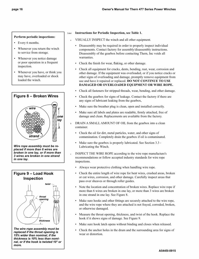
• Note the location and concentration of broken wires. Replace wire rope if more than 6 wires are broken in one lay, or more than 3 wires are broken in one strand in one lay. See Figure 8.
• Make sure hooks and other fittings are securely attached to the wire rope, and the wire rope where they are attached is not frayed, corroded, broken, or otherwise damaged.
• Measure the throat opening, thickness, and twist of the hook. Replace the hook if it shows signs of damage. See Figure 9.
• Make sure hook latch opens without binding and closes when released.
• Check the anchor holes in the drum and the surrounding area for signs of wear or distortion.
twist
throat opening
thickness
Figure 9 – Load Hook Inspection
The wire rope assembly must be replaced if the throat opening is 15% wider than nominal, if the thickness is 10% less than nomi-nal, or if the hook is twisted 10° or more.
Perform periodic inspections:
• Every 6 months.
• Whenever you return the winch to service from storage.
• Whenever you notice damage or poor operation in a frequent inspection.
• Whenever you have, or think you may have, overloaded or shock loaded the winch.
wire
strand
onelay
Figure 8 – Broken Wires
Wire rope assembly must be re-placed if more than 6 wires are broken in one lay, or if more than 3 wires are broken in one strand in one lay.

Owner's Manual for Thern 477 Series Power Winches page 17
A5445I-0915
correct incorrect
Figure 10 – Rope Diameter
diameter
The wire rope assembly must be replaced if the diameter measures less than the minimum diameter at any point.
wire rope diameter minimum diameter
1/4 in 15/64 in (.2344 in)
5/16 in 19/64 in (.2969 in)
d MOVE THE DRUM with your hands. Check for excessive movement indicating worn or loose gears, bearings, or shafts. Slight endplay in the driveshaft is normal. Excessive movement is caused by overloading or overheating, and is a sign that your application may require a larger winch.
e PLACE enough weight to keep the wire rope straight and tightly drawn.
• Measure the diameter of the wire rope, especially in areas where wear is noticeable. Replace the wire rope if the diameter measures below the minimum diameter at any point. See Figure 10.
f INSPECT THE FOUNDATION AND RIGGING
• Check mounting fasteners for stripped threads, wear, and other damage.
• Check the foundation for cracks, corrosion, and other damage.
g TEST WINCH PERFORMANCE by operating the winch with a load equal to the load rating.
• Listen for unusual noises, and look for signs of damage as you operate the winch.
• Make sure the wire rope winds evenly and tightly onto the drum. If it is loose or uneven, rewind it before continuing.
• Observe the rotating drum, look for signs of loose or misaligned bearings.
• Make sure the load moves smoothly, without hesitation or strain.
• Make sure the winch responds to the control device. It must rotate as shown on the control labels, and it must turn off when you release the control.
• Check the brake. Raise the load, then lower it and stop it a few feet off the ground. If the load continues to coast or creep, the brake needs adjustment. See Section 3.2 - Adjusting the Brake.
h DISCONNECT POWER and inspect power supply equipment.
• Check supply lines for wear, cuts, corroded connections, and other damage.
• Check control devices and other power supply components for signs of moisture, corrosion, burn marks, cracks, and other damage.
i CONNECT POWER.
• Check power supply at the motor and make sure it agrees with the motor rating. Do not operate the winch until proper power is supplied to the motor.
Completely correct all problems before continuing. Use the troubleshooting chart to help determine the cause of certain problems. See Table 2.

Owner's Manual for Thern 477 Series Power Winchespage 18
A5445I-0915
Table 1 – Inspection Checklist
damages problemsgeneral finish weathered, flaking, otherwise damaged winch jerks or hesitates during operation
parts cracked, bent, rusted, worn, otherwise damaged unusual noises, other signs of malfunction
fasteners stripped threads, bent, worn, otherwise damaged loose, not tightened to proper torque
reducer gears, bearings, or shafts loose, worn, otherwise damaged not properly lubricated
lubricant leakage lubricant contaminated
wire rope bent, crushed, otherwise damaged wire rope loosely or unevenly wound
broken wires, see Figure 8
replace if more than 6 wires in one lay, number per strand =
or 3 wires in one strand in one lay, are broken number per lay =
diameter reduced, see Figure 10
replace if diameter is excessively worn diameter =
end connections corroded, rusted, worn, otherwise damaged not securely attached
hook or other device twisted, bent, worn, otherwise damaged, see Figure 9 hook latch fails to close when released
replace if twist is 10 degrees or more, twist =
replace if throat width is 15% larger than nominal throat width =
replace if thickness is 10% less than nominal thickness =
drum anchor worn, distorted, otherwise damaged excessive movement or backlash
motor motor corroded, burnt out , otherwise damaged motor is sluggish or operates poorly
brake brake worn, corroded, otherwise damaged brake does not operate properly
power supply components corroded, burnt, otherwise damaged control device fails to control winch properly
supply lines worn, cut, corroded, otherwise damaged supply lines unprotected, obstructing traffic
connections loose, corroded, otherwise damaged power supply at motor =
clutch worn, bent corroded, otherwise damaged does not move freely or engage completely
labels and plates dirty, illegible, otherwise damaged loosely attached or missing
comments
authorized signature date
checked boxes indicate damage or problem in need of repair

Owner's Manual for Thern 477 Series Power Winches page 19
A5445I-0915
Table 2 – Troubleshooting ChartContact the factory for detailed instructions on re-sealing the gearbox if you are required to disassemble the gearbox for any reason. Disassembly of the gearbox before contacting Thern, Inc. voids all warranties.
problem cause correctionmotor won't run • circuit breaker tripped or fuse blown .................... reset circuit breaker or replace fuse
• poor power supply ................................................ inspect and repair as necessary
• power supply lines loose or damaged .................. inspect, repair and tighten as necessary
• power supply failure ............................................. check power supply source
• motor burnt out or damaged ................................. repair or replace as necessary
motor runs, drum doesn't turn • loose or broken spring pins or keys ...................... inspect and replace as necessary
• clutch disengaged ................................................ stop motor and engage clutch
• loose, stripped or broken gears ............................ inspect and replace as necessary
motor tries to turn but can't • unit overheated ..................................................... allow to cool
• load too heavy ...................................................... lighten load
• poor power supply ................................................ inspect supply circuit and repair as needed
• band brake too tight .............................................. loosen brake and readjust
• brake broken or locked ......................................... inspect and replace as necessary
• gears or bearings broken or locked ...................... inspect and replace as necessary
brake does not operate properly • wire rope installed improperly reinstall wire rope correctly
• brake adjusted incorrectly adjust brake
• brake worn or damaged ....................................... inspect and replace as necessary
• brake components seized up or damaged ........... inspect and repair as necessary
lubricant leakage • worn bearings ....................................................... inspect and replace as necessary
• oil seals leaking or damaged ................................ inspect and replace as necessary
• gaskets leaking or damaged ................................ tighten fasteners or replace gasket
• cracked or damaged reducer ............................... inspect and repair as necessary
• hydraulic equipment leaking or damaged ............. inspect and replace as necessary
excessive end play on drive shaft • loose or damaged keys or keyways ..................... inspect and replace as necessary
• excessively worn gears ........................................ inspect and repair as necessary
excessive worn gears or bearings • load too heavy ...................................................... lighten load
• poor lubrication of gears or bearings .................... inspect and lubricate as necessary
overheating • operated too long without rest .............................. allow to cool
• load too heavy ...................................................... lighten load
• poor lubrication ..................................................... inspect and lubricate as necessary
• breather plug clogged or damaged ...................... clean or replace breather plug
• bearing seized up ................................................. inspect and replace as necessary
unusual noises
high pitched squeak • poor lubrication ..................................................... inspect and lubricate as necessary
grinding noise • contaminated oil ................................................... drain, clean and lubricate the winch
• broken gears or bearings ..................................... inspect and replace as necessary
whining motor • load too heavy ...................................................... lighten load
• motor overheated ................................................. allow to cool
• motor bearings burnt out ...................................... replace motor or bearings
whistling noise • air leak in pneumatic equipment ........................... inspect and repair as necessary
rattling noise • loose fasteners or setscrews ................................ tighten all fasteners and screws
heavy thump during operation • contaminants in lubricant ...................................... drain, clean and lubricate the winch
• loose setscrews or keys in gears or shafts ........... inspect and repair as necessary
• bearings defective ................................................ inspect and replace as necessary

Owner's Manual for Thern 477 Series Power Winchespage 20
A5445I-0915
3.5 Repairing the Winch3.5.1 GET FACTORY AUTHORIZATION for all repairs. Unauthorized repairs
will void the warranty, and may lead to damage or failure of the winch.
3.5.2 REPLACE DAMAGED OR POORLY OPERATING PARTS with Thern repair parts.
3.5.3 REFINISH AREAS where the paint is worn or flaking. A good finish helps to protect against corrosion and weather damage.
a REMOVE THE FINISH from damaged areas, down to the bare metal.
b CLEAN THE AREA thoroughly.
c REPAINT with a high quality primer and finishing coat.
3.5.4 TO ORDER REPAIR PARTS, contact your local dealer. Include the following information when ordering:
• model number
• serial number (or code number)
• part number
• date purchased, and from whom
• description of what happened, or what is wrong
• your name and return address
477 Series – Configurations and Performance Characteristics 7
full load rating (lb) wire line speed (fpm) drum capacity (ft)1
model motor load 1st mid full rope 1st full 1st mid fullnumber motor description hp amps layer drum drum dia. (in) layer drum layer drum drum47712 115/1/60 VAC – 6 ft pendant 1.3 16 2000 1500 1200 5/16 13 22 13 40 904771AC-1PH 115/1/60 VAC – less controls 1.3 16 2000 1500 1200 5/16 13 22 13 40 904771AC-1PH2 115/230/1/60 VAC 1.5 16/8 2000 1500 1200 5/16 13 22 13 40 90 – less controls4771AC-3PH 4 230/460/3/60 VAC 1.5 5/2.5 2000 1500 1200 5/16 13 22 13 40 90 – less controls 4771DC 5 12 VDC – with 10 ft pendant 1.0 100 2000 1500 1200 5/16 13 22 13 40 904771PN 5, 6 pneumatic – less controls 1.2 2000 1500 1200 5/16 13 22 13 40 904771HY 5, 6 hydraulic – less controls 2.3 2000 1500 1200 5/16 13 22 13 40 904777 2 115/1/60 VAC – 6 ft pendant 1.3 16 2000 1500 1200 5/16 13 22 7 27 604777DC 6 12 VDC – with 10 ft pendant 1.0 100 2000 1500 1200 5/16 13 22 7 27 60
1 Actual drum capacities may be 25-30% less, due to nonuniform winding. Tension in wire rope will also affect drum capacity.2 Motor includes an 8 ft. power cord with grounded plug, and a push button pendant control on 6 ft cord.4 For Model 4771AC-3PH, please specify voltage when ordering.5 For pneumatic, hydraulic, and DC models, line speed is based on rated load, actual line speed varies with load weight and power supply.6 For Model 4771PN, ratings are for 80 cfm at 100 psi. For Model 4771HY, ratings are for 4 gpm at 1000 psi.7 Performance Characteristics are for standard products referred to in this manual. Non-standard products may vary from the original design. Contact Thern, Inc. for this information.
Important!
• It is your responsibility to determine when to replace parts. When considering whether to continue using a part or to replace it, remember that replacing it is the best way to avoid further equipment damage.
• Replace spring pins, retaining rings, and oil seals whenever the winch is disassembled for inspection or repair.
• During reassembly, use Loctite 598 Ultra Black to create a seal between the two halves of the gearbox. Contact the factory for detailed instructions. Disassembly of the gearbox before contacting Thern, Inc voids all warranties.
• Appoint a qualified person to be responsible for all repairs to the equipment.

Owner's Manual for Thern 477 Series Power Winches page 21
A5445I-0915
Important!
• Keep a record of what you ship, and when you send it.
4.1 Transporting the Winch4.1.1 REMOVE THE BREATHER PLUG and install a sealed oil plug to prevent
the loss of lubrication during shipment.
4.1.2 PACk THE WINCH in an upright position for transport, using the original packaging materials, if possible.
a FASTEN THE WINCH to a wooden base using lag bolts, to keep it from moving during transport.
b SEAL THE WINCH in plastic with a desiccant to help protect it from rust, corrosion, and other damage.
c CONSTRUCT WOODEN SIDES and top to enclose the winch in a solid protective crate.
d PACk LOOSE PARTS in small boxes or ship separately.
4.1.3 INSPECT THE WINCH according to the Instructions for Periodic Inspection before installing it in a new location.
4.2 Storing the Winch4.2.1 LUBRICATE THE WINCH as necessary, and make sure the breather plug is
clean and properly installed. Add a rust preventative for long term storage.
4.2.2 SEAL THE WINCH in plastic with a desiccant to help protect it from rust, corrosion, and other damage.
4.2.3 STORE THE WINCH upright, in a cool clean place away from corrosive chemicals and moisture.
4.2.4 ROTATE THE DRUM periodically to keep bearing and gears surfaces from becoming lacquered.
4.2.5 INSPECT THE WINCH according to the Instructions for Periodic Inspection before installing it for operation.
4.2.6 TEST INSULATION RESISTANCE in the motor to detect moisture damage. Refer to the motor manufacturer’s instructions.
4.2.7 LUBRICATE THE WINCH PROPERLY prior to operation. See section 3.3 - Lubricating the Winch.

Owner's Manual for Thern 477 Series Power Winchespage 22
A5445I-0915
3
2
1
4
4771 Series 4771 4771AC 4771DC 4771HY 4771PNitem description part no. part no. part no. part no. part no. qty.1 MoTor ADAPTer AsseMblY C2906 MTrADPT477AC C3115 C2948 C2949 12 reDuCer AsseMblY D1631 D1631 D1631 D1719 D1631 13 CAPsCrew sokHD .250-20NC x 1.500 A3449 A3449 A3449 A3449 A3449 84 CoNTrol AsseMblY C3048 — — — — 151 Hole seAl .50 — A4833 — — — 261 CAPsCrew sokHD .312-18NC x 1.750 — — — A3447 — 271 loCk wAsHer HelsPr .312 — — — A2925 — 2
1 Items 5, 6 and 7 not shown.
4777 Series 4777 4777AC 4777DC 4777HY 4777PNitem description part no. part no. part no. part no. part no. qty.1 MoTor ADAPTer AsseMblY C2906 MTrADPT477AC C3115 C2948 C2949 12 reDuCer AsseMblY D1706 D1706 D1706 D1726 D1706 13 CAPsCrew sokHD .250-20NC x 1.500 A3449 A3449 A3449 A3449 A3449 84 CoNTrol AsseMblY C3048 — — — — 151 Hole seAl .50 — A4833 — — — 261 CAPsCrew sokHD .312-18NC x 1.750 — — — A3447 — 271 loCk wAsHer HelsPr .312 — — — A2925 — 2
1 Items 5, 6 and 7 not shown.
4771 Power Winch

Owner's Manual for Thern 477 Series Power Winches page 23
A5445I-0915
477 Series Motor Adapter Assembly1 C2906 C3115 C2949item description part number qty part number qty part number qty1 MoTor b5495 1 b3046 1 b1738 12 2 MoTor ADAPTer D1169 1 D1169 1 D1169 13 THrusT beArINg .627 ID x 1.198 oD x .063 brZ A3243 1 A3243 1 A3243 14 sHIM seT A2646 1 A2646 1 A2646 15 sTAT-o-seAl .364 ID x .666 oD x .040 A3240 2 A3240 2 A3240 26 rADIAl bAll beArINg .500 ID x 1.125 oD x .313 sTl A3285 1 A3285 1 A3285 17 PIPe Plug HexsoC .375-18NPT x .425 sAe A3290 1 A3290 1 A3290 18 keY .188 x .188 x .875 4140 HT bes A3254 1 A3254 1 A3254 19 MoTor PINIoN b1695 1 b1695 1 b1695 110 CAPsCrew bTNHD NYlk .312-24NF x .750 blkox A3224 1 A3224 1 A3224 111 MoTor PINIoN wAsHer .319 ID x .900 oD A2636 1 A2636 1 A2636 112 CAPsCrew sokHD .375-16NC x 1.500 AlYsTl A3219 2 A3219 2 A3219 213 CAPsCrew bTNHD NYlk .375-16NC x 1.250 blkox A3218 2 A3218 2 A3218 214 oIl seAl .625 ID x 1.125 oD x .250 VIToN A5335 1 A5335 1 A5335 1
1 Contact factory for C2948 and MTrADPT477AC parts lists. 2 Models having a thick motor adapter D1285 can only be floor mounted. The D1285 motor adapter is 1.36 inches thick and D1169 is .98 inches thick.
1
14
2
354
13
12
8
911
106
13
512
7
C2906 Motor Adapter Assembly
2

Owner's Manual for Thern 477 Series Power Winchespage 24
A5445I-0915
2730
3124
2935
34
32
27
28
letteringface up
2625
3736
20
THIS SIDE UP
477 Series Reducer Assembly3 D1631 D1706item description part number part number qty.151 breATHer Plug .250-18NPT PlN sTl A2768 A2768 116 PIPe Plug HexsoC .250-18NPT x .425 sAe A2797 A2797 317 beArINg HolDer C1382 C1382 118 CAPsCrew sokHD .250-20NC x .750 AlYsTl A3245 A3245 8192 DruM sHAFT AsseMblY C2850 C3006 120 FrAMe D1257 D1257 121 sokHD seTsCrew A3746 A3295 122 DruM C1383 C1514 123 reTAININg rINg exT 1.188 sPrsTl A3287 A3287 124 HelICAl geAr b1728 b1728 125 sPrINg wAsHer .380 x .750 x .034 sPrsTl A3296 A3296 126 Hex JAM NuT .375-16NC ZNPl gr2 A3180 A3180 227 brAke DruM sPACer .660 ID x 1.25 oD A2642 A2642 228 brAke DruM wAsHer .660 ID x 2.00 oD A4058 A4058 129 brAke DruM AsseMblY b1700 b1700 130 keY .188 x .188 x .481 4140 HT ber A2637 A2637 131 reTAININg rINg exT .594 sPrsTl A3241 A3241 1322 worM sHAFT beArINg AsseMblY b2857 b2857 133 rADIAl bAll beArINg 1.181 ID x 2.441 oD x .629 A3251 A3251 1342 brAke bAND CoNNeCTor AsseMblY b2917 b2917 135 o-rINg .250 x .375 x .062 NITrIle A3297 A3297 236 o-rINg .625 x .750 x .063 NITrIle A3321 A3321 237 CoNNeCTor busHINg b1729 b1729 238 sloTTeD sPrINg PIN A4240 A3271 139 oIl seAl 1.375 ID x 2.562 oD x .375 A3261 A3261 1401,2 Pressure PlATe AsseMblY — b2085 11 Item 15 and 40 not shown. 2 Items 19, 32, 34 and 40 are sold as assemblies. 3 Contact factory for D1719 parts list.
D1631 Reducer Assembly

Owner's Manual for Thern 477 Series Power Winches page 25
A5445I-0915
39
332319
17
18
16
16
16
20
21
22
38D1631 Reducer Assembly

Owner's Manual for Thern 477 Series Power Winchespage 26
A5445I-0915
12/24 VOLT DC REVERSING
12/24 VOLT DC SUPPLY
+ -
UP PB
DWN PB
SV1
SV2
SV1 SV2
12/24 VOLT DC MOTOR
JMPR1 JMPR2 JMPR3
Models ending in -DC are equipped with DC MotorsElectric DC Schematic for 12/24 volt DC Controls1
(Controls sold separately)
477 Series Electric AC Schematic for B5495 Motor1
1 schematics are for standard products referred to in this manual. Non-standard products may vary from the original design. If you did not receive a schematic or have questions please contact Thern, Inc. for this information.
Owner's Manual for Thern 477 Series Power Winches page 27
A5445I-0915
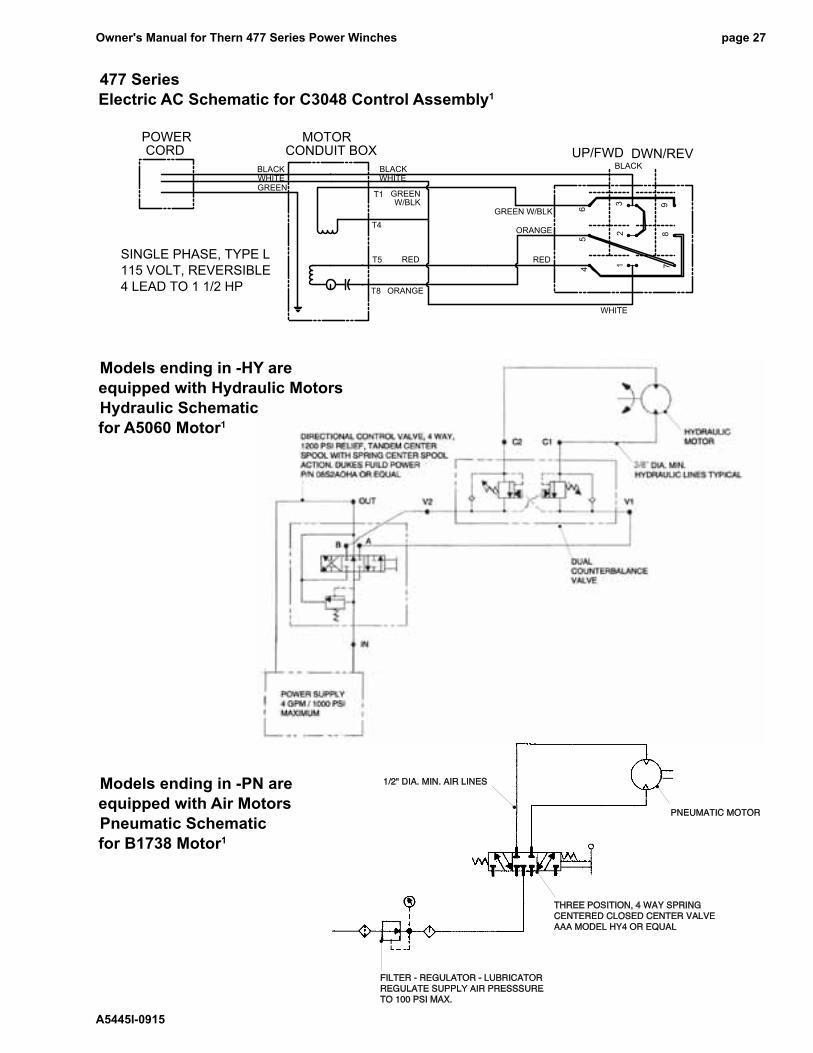
477 Series Electric AC Schematic for C3048 Control Assembly1
RED
T8
T5
POWERCORD CONDUIT BOX
MOTOR
GREENWHITEBLACK
GREENW/BLK
T4
T1
BLACK
97
8
6
31
2
45
WHITEBLACK
GREEN W/BLK
RED
ORANGE
WHITE
ORANGE
UP/FWD DWN/REV
SINGLE PHASE, TYPE L115 VOLT, REVERSIBLE4 LEAD TO 1 1/2 HP
Models ending in -PN are equipped with Air MotorsPneumatic Schematic for B1738 Motor1
Models ending in -HY are equipped with Hydraulic MotorsHydraulic Schematic for A5060 Motor1
1/2" DIA. MIN. AIR LINES
FILTER - REGULATOR - LUBRICATORREGULATE SUPPLY AIR PRESSSURETO 100 PSI MAX.
THREE POSITION, 4 WAY SPRINGCENTERED CLOSED CENTER VALVEAAA MODEL HY4 OR EQUAL
PNEUMATIC MOTOR

Thern, Incorporated5712 Industrial Park roadwinona, MN 55987
PH 507-454-2996FAx 507-454-5282
eMAIl: [email protected]
Thern Europewindmolen 227609 NN AlmeloNetherlands
PH +31-548-659-052
eMAIl: [email protected]