read me table of contents - ansi webstore
TRANSCRIPT

READ ME
TABLE OF CONTENTS
This is a preview of "IAPMO/ANSI UPC 1-201...". Click here to purchase the full version from the ANSI store.

2018UNIFORMPLUMBINGCODE
®
an american national standard
iaPmo/ansi UPc 1 – 2018
This is a preview of "IAPMO/ANSI UPC 1-201...". Click here to purchase the full version from the ANSI store.

copyright © 2018international association of Plumbing and mechanical officials all rights reserved
no part of this work may be reproduced or recorded in any form or by any means, except as may be expressly permitted in writing by the publisher.
twenty-eighth edition First Printing, January 2018second Printing, may 2018third Printing, January 2019Fourth Printing, october 2019
Published by the international association of Plumbing and mechanical officials4755 e. Philadelphia street • ontario, ca 91761-2816 – Usa main Phone: (909) 472-4100 • main Fax: (909) 472-4150
This is a preview of "IAPMO/ANSI UPC 1-201...". Click here to purchase the full version from the ANSI store.

Important Notices and Disclaimersthe 2018 edition of the Uniform Plumbing Code is developed through a consensusstandards development process approved by the american national standards institute.this process brings together volunteers representing varied viewpoints and interests toachieve consensus on plumbing issues. While the international association of Plumbingand mechanical officials (iaPmo) administers the process and establishes rules to promotefairness in the development of consensus, it does not independently test, evaluate, or verifythe accuracy of any information or the soundness of any judgments contained in its codesand standards.
iaPmo disclaims liability for any personal injury, property, or other damages of any naturewhatsoever, whether special, indirect, consequential, or compensatory, directly or indirectlyresulting from the publication, use of, or reliance on this document. iaPmo also makes noguarantee or warranty as to the accuracy or completeness of any information publishedherein.
in issuing and making this document available, iaPmo is not undertaking to renderprofessional or other services for or on behalf of any person or entity. nor is iaPmoundertaking to perform any duty owed by any person or entity to someone else. anyoneusing this document should rely on his or her own independent judgment or, as appropriate,seek the advice of a competent professional in determining the exercise of reasonable carein any given circumstances.
Updating IAPMO CodesUsers of iaPmo codes should be aware that iaPmo codes may be amended from time totime through the issuance of tentative interim amendments or corrected by errata. iaPmocodes consist of the current edition of the document together with any tentative interimamendment and any errata in effect.
in order to determine whether an iaPmo code has been amended through the issuance oftentative interim amendments or corrected by errata, please visit the iaPmo Group codesinformation pages on iaPmo’s website (www.iapmo.org). the codes information pagesprovide a list of iaPmo codes with up-to-date, specific information including any issuedtentative interim amendments and errata.
to access the codes information pages for a specific code, go to http://codes.iapmo.org toselect from the list of iaPmo codes. For tentative interim amendments, go to the standardcouncil decisions. For errata, select the archived revision information.
iii
This is a preview of "IAPMO/ANSI UPC 1-201...". Click here to purchase the full version from the ANSI store.

Origin and Developmentthe advantages of a statewide adopted Uniform Plumbing Code are recognizedthroughout the industry. disorder in the industry because of widely divergent plumbingpractices and the use of many different, often conflicting, plumbing codes by localjurisdictions influenced the Western Plumbing officials association (now the internationalassociation of Plumbing and mechanical officials [iaPmo]) to form a committee. thiscommittee of plumbing inspectors, master and journeyman plumbers, and plumbingengineers, backed by public utility companies and the plumbing industry to create a basicplumbing document for general use. the product of this effort, the first edition of theUniform Plumbing Code® (UPc®) was adopted by iaPmo in 1945. the widespread useof this code over the past seven decades by jurisdictions throughout the United statesand internationally is testament to its merit.
Publishing the 2003 Uniform Plumbing Code, is a significant milestone because it is thefirst time in the history of the United states, a plumbing code was developed through atrue consensus process. the 2018 edition represents the most current approaches in theplumbing field and is the sixth edition developed under the ansi consensus process.contributions to the content of this code consists of diverse interests as consumers,enforcing authorities, installers/maintainers, labor, manufacturers, research/standards/testing laboratories, special experts, and users.
the Uniform Plumbing Code provides consumers with safe and sanitary plumbingsystems while, at the same time, allowing latitude for innovation and new technologies.the public at large is invited and encouraged to take part in iaPmo’s open consensuscode development process. this code is updated every three years. the UniformPlumbing Code is dedicated to all those who, in working to achieve “the ultimateplumbing code,” have unselfishly devoted their time, effort, and personal funds to createand maintain this, the finest plumbing code in existence today.
the Uniform Plumbing Code updates every three years in revision cycles that begin twiceeach year that takes two years to complete.
each revision cycle advances according to a published schedule that includes final datesfor all major events and contains four basic steps as follows:1. Public and committee Proposal stage;2. comment stage;3. association technical meeting;4. council appeals and issuance of code.
iaPmo develops “full consensus” codes built on a foundation of maximum participation andagreement by a broad range of interests. this philosophy has led to producing technicallysound codes that promote health and safety, yet do not stifle design or development.
it is important to stress that; the process remains committed to the principles of consensuscode development where consensus technical committees and correlating committeesrevise codes. the public and membership is offered multiple opportunities to debate, provideinput and raise concerns through amending motions at the annual assembly considerationsession. anyone may submit an appeal related to the issuance of a document through theiaPmo standards council.
the 2018 Uniform Plumbing Code is supported by the mechanical contractors associationof america (mcaa), the Plumbing-Heating-cooling contractors national association (PHcc-na), the United association (Ua), and the World Plumbing council (WPc). the presence ofthese logos, while reflecting support, does not imply any ownership of the copyright to theUPc, which is held exclusively by iaPmo. Further, the logos of these associations indicatethe support of iaPmo’s open consensus process being used to develop iaPmo’s codes andstandards.
iv
FOREWORD
This is a preview of "IAPMO/ANSI UPC 1-201...". Click here to purchase the full version from the ANSI store.

the addresses of the organizations are as follows:asse – 18927 Hickory creek drive, suite 220 • monkena, il 60448 • (708) 995-3019mcaa – 1385 Piccard drive • rockville, md 20850 • (301) 869-5800PHcc-na – Po Box 6808 • Falls church, Va 22040-6808 • (800) 533-7694Ua – three Park Place • annapolis, md 21401 • (410) 269-2000WPc – World Plumbing council secretariat, auf der mauer 11 • Postfach cH 8021 • Zurich
switzerland • www.WorldPlumbing.org
Adoptionthe Uniform Plumbing Code is available for adoption and use by jurisdictions in theUnited states and internationally. its use within a governmental jurisdiction isaccomplished through adoption by reference in accordance with applicable jurisdictionallaws. at adoption, jurisdictions should insert the applicable information in bracketed wordsin the sample ordinance. the sample legislation for adoption of the Uniform PlumbingCode on page xii provides key components, regulations and resolutions.
Revision Markingssolid vertical lines in the margins indicate a technical change from the requirements of the2015 edition. an arrow ( ) in the margin indicates where an entire section, paragraph,exception or table has been deleted, or an item in a list of items or a table has been deleted.
a double right angle («) in the margin indicates that the text or a table has been relocatedwithin the code. the table found on page xiv points out the relocations in the 2018 editionof the Uniform Plumbing Code.
tia indicates that the revision is the result of a tentative interim amendment.
For further information on tentative interim amendments see section 5 of the iaPmoregulations Governing committee Projects available at http://codes.iapmo.org/
a reference in brackets [ ] following a section or paragraph indicates material that has beenextracted from another document. this reprinted material is not the complete and officialposition of the source document on the referenced subject that is represented by thestandard in its entirety. material contained in this document that is taken or extracted fromnFPa standards is used with permission of the national Fire Protection association. thismaterial is not the complete and official position of the nFPa on the reference subject, whichis represented solely by the relevant standard in its entirety. nFPa standards can beaccessed at www.nfpa.org. in addition, this extracted material may include revisions ormodifications developed through iaPmo’s standards development process. therefore,nFPa disclaims responsibility for the content of this code.”
text that is extracted pursuant to iaPmo’s extract Guidelines, but outside of the regularrevision process is denoted with the use of the source document in the margin. this text isnot fully processed by iaPmo in accordance with ansi’s public announcement consensusrequirements for an american national standard (ans) nor approved by ansi’s Board ofstandards review. the next revision cycle processes such text in accordance with thoserequirements.
v
FOREWORD
TIATIATIATIA
This is a preview of "IAPMO/ANSI UPC 1-201...". Click here to purchase the full version from the ANSI store.
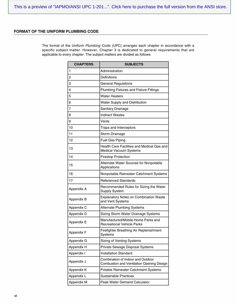
the format of the Uniform Plumbing Code (UPc) arranges each chapter in accordance with aspecific subject matter. However, chapter 3 is dedicated to general requirements that areapplicable to every chapter. the subject matters are divided as follows:
CHAPTERS SUBJECTS
1 administration
2 definitions
3 General regulations
4 Plumbing Fixtures and Fixture Fittings
5 Water Heaters
6 Water supply and distribution
7 sanitary drainage
8 indirect Wastes
9 Vents
10 traps and interceptors
11 storm drainage
12 Fuel Gas Piping
13Health care Facilities and medical Gas andmedical Vacuum systems
14 Firestop Protection
15alternate Water sources for nonpotableapplications
16 nonpotable rainwater catchment systems
17 referenced standards
appendix arecommended rules for sizing the Watersupply system
appendix Bexplanatory notes on combination Wasteand Vent systems
appendix c alternate Plumbing systems
appendix d sizing storm Water drainage systems
appendix emanufactured/mobile Home Parks andrecreational Vehicle Parks
appendix FFirefighter Breathing air replenishmentsystems
appendix G sizing of Venting systems
appendix H Private sewage disposal systems
appendix i installation standard
appendix Jcombination of indoor and outdoorcombustion and Ventilation opening design
appendix K Potable rainwater catchment systems
appendix l sustainable Practices
appendix m Peak Water demand calculator
vi
FORMAT OF THE UNIFORM PLUMBING CODE
This is a preview of "IAPMO/ANSI UPC 1-201...". Click here to purchase the full version from the ANSI store.

the following is a summary of the scope and intent of the provisions addressed within the chapters and appendices of theUniform Plumbing Code:
Chapter 1 Administration. chapter 1 regulates the application, enforcement, and administration of subsequent requirements of the code. as well asestablishing the scope of the code, this chapter is concerned with enforcing the requirements contained in the body of the code. aplumbing code, as with any other code, is intended to be adopted as a legally enforceable document to safeguard health, safety,property and public welfare. the code cannot be effective without satisfactory provisions for its administration and enforcement.the authority Having Jurisdiction is to review the proposed and completed work and to decide whether a plumbing systemconforms to the code requirements. as a public servant, the authority Having Jurisdiction enforces the code in an unbiased, propermanner. the design professional is responsible for the design of a safe plumbing system. the contractor is responsible forinstalling the system in accordance with the plans.
Chapter 2 Definitions. to maintain consistency and encourage the use of common terminology, chapter 2 establishes definitions to provide clarity ofterms and promote the use of a common language throughout the code. Understanding definitions within the context of theirapplication enables greater collaboration, efficiency, standardization and interpretation in applying and enforcing terms usedthroughout the code. codes are technical documents, and every term can impact the meaning of the code text. terms notdefined have a normally accepted meaning.
Chapter 3 General Regulations. chapter 3 regulates the general requirements, not specific to other chapters, for installing plumbing systems. manyregulations are not specific plumbing requirements, but relate to the overall plumbing system. this chapter contains safetyrequirements for installing plumbing and also contains nonplumbing requirements for identifying pipe, pipe fittings, traps,fixtures, materials and devices used in plumbing systems. listing method of approval, based on applicable nationallyrecognized standards, for the safe and proper installation of plumbing systems is essential to ensure protection of publichealth, safety, and welfare. the safety requirements provide protection for piping, material, and structures, with provisions forinstallation practices, removing stress and strain of the pipe, sleeving, and hanger support. the building’s structural stability isprotected by the regulations for cutting and notching of structural members.
Chapter 4 Plumbing Fixtures and Fixture Fittings.this chapter regulates the minimum number of plumbing fixtures of a specific type and quality for each building. the fixturesmust be properly installed to be usable by the individuals occupying the building. the quality and design of every fixture mustconform to the applicable referenced standard. compliance with this chapter will result in a building or structure havingacceptable plumbing fixtures for the sanitary, hygienic, cleaning, washing and food preparation needs of the occupants.
Chapter 5 Water Heaters. chapter 5 regulates the design, approval, installation, and safety devices of fuel burning and other types of water heaters withthe combustion air requirements for ventilation and dilution of flue gases for appliances installed in buildings. this chapterdoes not apply to direct vent appliances. in addition, this chapter regulates the design, construction, installation, maintenanceof chimneys, vents and their connections to fuel burning appliances. methods to supply combustion air may be supplied froman indoor air supply, outdoor air supply, a combination of indoor and outdoor air supply, mechanical air supply, or anengineered system. combustion air provisions are based on the number of openings and the total opening size requiredbased on the total energy input rating of the appliance. acceptable air supply for combustion and ventilation is necessary forproper operation of fuel burning appliances. a shortage of combustion air can result in incomplete combustion and productionof poisonous gases, such as carbon monoxide or appliance overheating. Ventilation air provides cooling for the appliancecasing and internal controls. inadequate ventilation of the space in which an appliance is installed can result in increasedsurrounding temperatures that stress the appliance itself or other appliances in the vicinity.
Chapter 6 Water Supply and Distribution. chapter 6 regulates the design, material and installation of water supply and distribution systems, including residential firesprinklers. the water supply and distribution system is designed to achieve the correct water pressure and flow rates andavoid cross connections. For fixtures to perform properly, an acceptable supply of potable water is essential to their operation
vii
FORMAT OF THE UNIFORM PLUMBING CODE
This is a preview of "IAPMO/ANSI UPC 1-201...". Click here to purchase the full version from the ANSI store.

and use. cross connections and backflow are ranked as the highest priority because of the long history of recognized healthrisks posed by cross connections, outbreaks, or cases of waterborne disease. Piping materials and components are evaluatedfor their possible effect on the potable water with which they are in contact. the intent is to control the potential adverse healtheffects produced by indirect additives, products, and materials that come in contact with potable water. When selectingmaterials for water supply and distribution systems, consider water pressure, water temperature, compatibility with the watersupply, durability, support, and sustainability.
in addition, this chapter regulates the design, location, materials, and installation of multipurpose and stand-alone sprinklersystems that do not include the use of antifreeze. Where systems are installed as a portion of the water distribution systemunder the requirements of this chapter and are not provided with a fire department connection, backflow protection for thewater supply system is not required.
Chapter 7 Sanitary Drainage. this chapter regulates the design and installation of sanitary drainage systems to ensure they will work as intended. drainagepiping should not be oversized nor undersized, and constructed of approved materials to guard against fouling, deposit ofsolids, clogging, and with cleanouts so arranged that the pipes may be readily cleaned. the purpose of the sanitary drainagesystem is to remove effluent discharged from plumbing fixtures and other equipment to an approved point of disposal, such asa public sanitary system or private sewage disposal system.
the basics of a sanitary drainage system include public and private sewage disposal; selection of materials; installation of thebuilding drain and sewer; joining methods for pipe and fittings; drainage fixture units for sizing the drainage system; sumpsand ejectors; vent sizing and length of vents; and testing.
Chapter 8 Indirect Wastes. chapter 8 regulates indirect waste connections that are required for plumbing fixtures and plumbing appliances dealing withfood preparation, dishwashing, potable liquids, and similar equipment. an indirect connection prevents sewage from backingup into a fixture or appliance, thus providing protection against potential health hazards. the waste pipe discharges throughan air gap or air break into a waste receptor or standpipe. the protection in the form of an air gap is necessary when thecontamination is a potential health hazard or cross connection with the potable water system. Where there is no possibility ofcontaminating the potable water (nonpotable discharge), the indirect waste pipe may connect in the form of an air break. thismethod is often preferred to prevent splashing. in addition, health care facilities and special wastes must be protected fromcontamination that may result from the connection to the drainage system. the waste must be treated to prevent any damageto the piping or sewage treatment process. Waste receptors are sized and designed to prevent splashing and allow for peakdischarge conditions.
Chapter 9 Vents. chapter 9 regulates the material, design, and installation of vents. a vent system is a pipe or pipes installed in a drainagesystem that provide a flow of air to and from the system to ventilate it, provide a circulation of air to eliminate trap siphonage,and reduce back-pressure and vacuum surge. in addition, vents provide the rapid and silent flow of waste without exposingoccupants of the building to any sewer gases. Proper installation of vents is crucial, as a telltale sign that there is a problem inthe drain and vent system is related to the elevation of the horizontal portion of the venting. Venting is not limited to sanitarydrainage systems. Venting methods are applicable to other drainage systems such as those for chemical waste, graywaterwaste, and clear water waste. sizing the venting system is directly tied to the design of the drainage system. For example, thevelocities in the drainage system and its peak flow rates affect the diameters in the venting system. Where the vertical distancebetween a fixture outlet and trap is excessive, velocities in the entire drainage system will be greater than those in the ventsizing table. all venting methods in this chapter are categorized as either dry vents or wet vents. Vent stacks, stack vents,branch vents, island vents, relief vents, and individual vents are dry vents. Wet vents (horizontal or vertical), circuit vents,combination drain and vents are versions of “wet venting” in which the vent is wetted by drainage flow.
Chapter 10 Traps and Interceptors. chapter 10 regulates the material, design, and installation of traps, interceptors, and separators. traps are required ondrainage type plumbing fixtures and must be self-scouring without interior partitions. interceptors, on the other hand, aredesigned to control what goes down a drain. interceptors are used to keep harmful substances from entering the sanitarydrainage system, such as grease, sand, oil and other materials. the retained materials need periodic removal to maintain
viii
FORMAT OF THE UNIFORM PLUMBING CODE
This is a preview of "IAPMO/ANSI UPC 1-201...". Click here to purchase the full version from the ANSI store.

ix
efficiency and function of the separating device. the capacity of an interceptor is based on retention and flow rate. there aremany types of interceptors that are used at beauty salons, hospitals, meat, fish or foul packaging, refineries, repair garages, gasstations, car washing facilities, various plants, factories, and processing sites. the designer of the building is responsible forlocating interceptors with the expectation for the frequency of maintenance, ease of cleaning and floor space for equipment.
Chapter 11 Storm Drainage. chapter 11 regulates the removal of stormwater from roofs, yards, paved areas, and similar areas. the objective of stormdrainage systems is to provide a conduit or channel through which runoff will be carried from a point of collection to a point ofdisposal; this protects the property and the public from the uncontrolled flow of runoff and ensures that drains and inlets areadequately sized to receive the volume of runoff that flows to the drains. For the purpose of system design, it’s necessary tospecify the duration of a selected storm. all methods used to determine volumes and peak flow use historical data. drainlocation must be coordinated with the architectural design of the building. When selecting the type of roof drain to use, the roofconstruction and its thickness, along with the intended use of the roof, are required. Where the roof perimeter extends abovethe roof in such a manner that water is entrapped and causes ponding, or if any portion of the roof is designed so water canpond, secondary drainage is required. Where secondary drainage is required, scuppers, or a secondary system of roof drainsand pipes, are installed to prevent the accumulation of excessive rainwater.
Chapter 12 Fuel Gas Piping.chapter 12 regulates the installation of gas piping in a building, structure or within the property lines of buildings up to 5 psi.Gas piping systems must supply the minimum volume of gas required by each gas appliance to perform their proper operationunder working conditions without exceeding the maximum pressure specified by each manufacturer. Because of the hazardsassociated with fuel gas, it is important to ensure the gas system has been inspected and tested, and that it is safe to turn onthe gas supply to the building.
Chapter 13 Health Care Facilities and Medical Gas and Medical Vacuum Systems.chapter 13 regulates the installation, inspection, testing, maintenance, performance, and safe practices for medical gas andvacuum systems located in health care facilities. this chapter addresses the installation and maintenance of health carefixtures, devices, and equipment. the purpose of medical gas and medical vacuum systems is to provide safe and sufficientflows at required pressures to the medical gas outlet or vacuum inlet terminals. system design and layout should allowconvenient access by the medical staff to outlet and inlet terminals, valves, and equipment during patient care oremergencies, as safety is of primary concern.
Chapter 14 Firestop Protection.chapter 14 regulates piping penetrations of fire-resistance-rated walls, partitions, floors, floor and ceiling assemblies, roof andceiling assemblies, or shaft enclosures through firestopping. to firestop is to create a physical barrier that impedes the spreadof smoke, gases, and flames from one compartment in the building design to the next. the firestop is seen as a part that isessential to protecting the lives of people who live or work in the structure, increasing the chances of not succumbing tosmoke or gases before they are able to evacuate the building. Fireproofing of this type helps to restore the fire-resistantproperties of the building materials before the openings were created as part of the construction process.
Chapter 15 Alternate Water Sources for Nonpotable Applications.chapter 15 regulates gray water sources, reclaimed (recycled) water sources and on-site treated nonpotable water systems.Water sources include subsurface irrigation, subsoil irrigation, and mulch basin systems. subsoil water irrigation provides ameans to disperse shallow drip irrigation lines and mulch basins that collect and spread water in various applications. thereclaimed water provisions to on-site nonpotable water systems include gray water and other nonpotable water sources that areused for on-site applications. Water reuse is integral to sustainable water management because it allows water to remain in theenvironment and be preserved for future use while meeting the water requirements of the present. Water reuse reduces energyuse by removing added potable water treatment, offsetting water demands, and providing water for energy production.
Chapter 16 Nonpotable Rainwater Catchment Systems. chapter 16 regulates nonpotable rainwater catchment systems that include irrigation; toilet and urinal flushing with propertreatment; provisions where permits are required; maintenance of alternate water sources; and minimum water quality. thischapter provides guidance on how to optimize rainwater use while ensuring there is a decrease of risk to consumers from poor
FORMAT OF THE UNIFORM PLUMBING CODE
This is a preview of "IAPMO/ANSI UPC 1-201...". Click here to purchase the full version from the ANSI store.

x
FORMAT OF THE UNIFORM PLUMBING CODE
design, installation, and maintenance. rainwater harvesting is the process of capturing, chan neling, and storing water runoff forlater use. most systems are constructed of three principal components: the catchment area, the collection device, and theconveyance system.
Chapter 17 Referenced Standards.
chapter 17 provides two comprehensive tables with referenced standards. the standards listed in table 1701.1 are applied asindicated in the applicable reference section(s). a list of additional standards, publications, practices, and guides that are notreferenced in specific sections appear in table 1701.2 and shall be submitted to the authority Having Jurisdiction for approval.
referenced standards set forth specific details of accepted practices, materials specifications, or test methods in manyspecialized applications. standards provide an efficient method of conveying complex information and specifications on theperformance requirements for materials, products, systems, application, and installation. the manner and purpose for astandard’s use and, in turn, code compliance, must be definitive in all references to the standard. if the standard is intended tobe a requirement for judging code compliance, the code must state its intent for use. the standard should adequately address adefined need and at the same time specify the minimum performance requirements, technical characteristics and methods oftesting, and required test results.
the referenced standards table is organized in a manner that makes it easy to find specific standards in alphabetical order,and by acronym of the publishing agency of the standard. the table lists the title of the standard, the edition, any addenda,and the section or sections of the code that reference the standard. contact information for each publishing agency isprovided at the end of the chapter.
Appendix A Recommended Rules for Sizing the Water Supply System.
appendix a provides a method of sizing the water supply and distribution system that provides precise calculations toestablish the proper pressures and flow to the system’s fixtures. the goal of sizing the system is to deliver an acceptablevolume of water to the most hydraulically remote fixture during minimum pressure and maximum flow conditions; providesatisfactory water pressure to the most hydraulically remote fixture during minimum pressure and maximum flow conditions;and to prevent excessive water velocity during maximum flow conditions.
Appendix B Explanatory Notes on Combination Waste and Vent Systems.
appendix B contains general guidelines for the design and installation of combination waste and vent systems. thesesystems are designed for waste piping and are purposely oversized to serve as both a waste and vent pipe to avoid excessivepneumatic effects at fixture drains.
Appendix C Alternate Plumbing Systems.
the intent of this appendix is to provide clarification of procedures for the design and approval of engineered plumbingsystems, alternate materials, and equipment that are not specifically covered in other parts of the code. alternative methodsare allowed to be used where approved by the authority having jurisdiction. approval of alternatives is based on ademonstration showing that the method or material used is at least equivalent in strength, deflection, and capacity to thatprovided by the prescriptive methods and materials.
Appendix D Sizing Storm Water Drainage Systems.
appendix d provides general guidelines for the sizing of stormwater drainage systems. there are two pieces of informationthat must always be a given. they are the roof size and the rate of rainfall for the area.
Appendix E Manufactured/Mobile Home Parks and Recreational Vehicle Parks.
the provisions of this appendix apply to the plumbing and drainage systems of mobile home and recreational vehicle parks.these provisions also apply to the use, maintenance, and installation for supplying fuel gas, water, electricity, and disposal ofsewage from accessory buildings or structures, and building components.
This is a preview of "IAPMO/ANSI UPC 1-201...". Click here to purchase the full version from the ANSI store.

xi
Appendix F Firefighter Breathing Air Replenishment Systems.appendix F provides guidance on installing firefighter breathing air replenishment systems. system components includeoutside fire department connection panel, interior air fill panel or station, interconnected piping distribution system andpressure monitoring switch. Fire departments access the system through an outside connection panel and are able to pumpair into the system. the firefighters inside the structure access the system at fill stations that are found throughout thebuilding. the piping distribution system is made from stainless tubing or other approved materials. it delivers compressed airto the building interior air fill stations and interior air fill panels. the tubing also acts as a conduit in the interior of the buildingbetween the outside connection panel and the air storage system. if the system becomes over-pressurized, the air monitoringsystem also acts as a pressure relief. a system isolation valve is placed alongside each interior air fill station and interior air fillpanel to isolate the system.
Appendix G Sizing of Venting Systems. appendix G provides added information on the sizing of gas vents. this appendix is useful to the end user for the proper sizing ofventing systems. a series of examples are given that show how to use the tables and other requirements of chapter 5.
Appendix H Private Sewage Disposal Systems. appendix H provides general guidelines for the materials, design, and installation of new or existing private sewage disposalsystems. Where a building cannot be served by a public sewer system, the building site must be provided with a system fortreating the waste water generated from the use of plumbing fixtures in the building. the appendix addresses site evaluations,materials, soil absorption systems, holding tanks, cesspools and on-site waste-water treatment systems. Private sewagedisposal systems must be designed based on the soil conditions, constructed using approved materials, and installedaccording to prescribed dimensions.
Appendix I Installation Standard for PEX Tubing Systems for Hot- and Cold-Water Distribution. the installation standard provides guidelines for sdr 9 crosslinked polyethylene (PeX) tubing and fittings intended for hot-and cold-water distribution systems. Provisions include joining methods, clearances, sizing and flow velocities, handling,storage, exposure to heat and chemicals, and thermal expansion and contraction.
Appendix J Combination of Indoor and Outdoor Combustion and Ventilation Opening Design. appendix J provides an example of how to determine the required combination of indoor and outdoor combustion air openingsizes for appliances. the combustion air example also provides a table that contains the required volume of a space per theappliance BtU/h input that is based on the standard method.
Appendix K Potable Rainwater Catchment Systems. Potable rainwater catchment system is defined as a system that uses the principal of collecting and using rain from a rooftopor other man-made, aboveground collection surface. this appendix applies to new rainwater catchment installations, as wellas changes, additions, maintenance, and repairs to existing installations. rainwater harvesting is the practice of collecting thewater produced during rainfall events before it has a chance to run off into a river or stream or soak into the ground andbecome groundwater.
Appendix L Sustainable Practices. this appendix provides a comprehensive set of technically sound provisions that encourage sustainable practices and workstoward improving the design and construction of plumbing systems that result in a positive long-term environmental impact.environmental sustainability is important because it involves natural resources that human beings need for economic ormanufactured capital. their sustainability is defined by their reliance on infinitely available resources that are naturallyoccurring, constant, and free to access.
Appendix M Peak Water Demand Calculator. this appendix provides a method for estimating the demand load for the building water supply and principal branches forsingle- and multi-family dwellings with water-conserving plumbing fixtures, fixture fittings, and appliances.
FORMAT OF THE UNIFORM PLUMBING CODE
This is a preview of "IAPMO/ANSI UPC 1-201...". Click here to purchase the full version from the ANSI store.

the Uniform codes are designed to be adopted by jurisdictions through an ordinance. Jurisdictions wishing toadopt the 2018 Uniform Plumbing Code as an enforceable regulation governing plumbing systems by referenceshould ensure the legal basis under which adoption and implementation are included in the ordinance.
the following sample ordinance is a guide for drafting an ordinance for adoption that addresses key componentsregulations and resolutions.
ORDINANCE NO.
an ordinance of the [JUrisdiction] adopting the 2018 edition of the Uniform Plumbing Code, regulating andcontrolling the design, construction, quality of materials, erection, installation, alteration, repair, location,relocation, replacement, addition to, use or maintenance of plumbing systems in the [JUrisdiction]; providingfor the issuance of permits and collection of fees therefor; repealing ordinance no. of the [JUrisdiction] andall other ordinances and parts of the ordinances in conflict therewith.
the [GoVerninG BodY] of the [JUrisdiction] does ordain as follows:
section 1 codes adopted by reference. that certain documents, three (3) copies of which are on file in theoffice of the [JUrisdiction's KeePer oF records] and the [JUrisdiction], being marked anddesignated as the 2018 Uniform Plumbing Code, including appendix chapters [Fill in tHe aPPendiXcHaPters BeinG adoPted], as published by the international association of Plumbing and mechanicalofficials, be and is hereby adopted as the code of the [JUrisdiction], in the state of [state name]regulating and controlling the design, construction, quality of materials, erection, installation, alteration, repair,location, relocation, replacement, addition to, use or maintenance of plumbing systems as herein provided;providing for the issuance of permits and collection of fees therefor; and each and all of the regulations,provisions, penalties, conditions and terms of such 2018 Uniform Plumbing Code on file in the office of the[JUrisdiction] are hereby referred to, adopted, and made a part hereof, as if fully set out in this ordinance.
section 2 modifications. the following sections are hereby revised:section 101.1. insert: [name oF JUrisdiction]section 104.5. insert: [aPProPriate Fee scHedUle]
section 3 conflicting ordinances repealed. that ordinance no. of [JUrisdiction] entitled [title oF tHe ordinance or ordinances in eFFect at tHe Present time so tHat tHeY Will BerePealed BY mention] and all other ordinances or parts of ordinances in conflict herewith are hereby repealed.
section 4 Preemption. [JUrisdiction] hereby fully occupies and preempts the entire field of regulation ofdesign, construction, quality of materials, erection, installation, alteration, repair, location, relocation,replacement, addition to, use or maintenance of plumbing systems; and provision for the issuance of permitsand collection of fees therefor; within the boundaries of [JUrisdiction]. [as aPProPriate] cities, towns,and counties or other municipalities may enact only those laws and ordinances relating to this field asspecifically authorized by state law and consistent with this ordinance. local laws and ordinances that areinconsistent with, more restrictive than, or exceed the requirements of [ordinance no.] shall not be enactedand are hereby expressly preempted and repealed, regardless of the nature of the code, charter, or home rulestatus of such city, town, county, or municipality.
section 5 severability. that if any section, subsection, sentence, clause or phrase of this ordinance is, for anyreason, held to be unconstitutional, such decision shall not affect the validity of the remaining portions of thisordinance. the [GoVerninG BodY] hereby declares that it would have passed this ordinance, and eachsection, subsection, clause or phrase thereof, irrespective of the fact that any one or more sections, subsections,sentences, clauses and phrases be declared unconstitutional.
section 6 legal notice. that the [JUrisdiction's KeePer oF records] is hereby ordered and directed tocause this ordinance to be published. (an additional provision may be required to direct the number of times theordinance is to be published and to specify that it is to be in a newspaper in general circulation. Posting mayalso be required.)
section 7 Violations and Penalties. [incorPorate Penalties For Violations]
section 8 effective date. that this ordinance and the rules, regulations, provisions, requirements, orders andmatters established and adopted hereby shall take effect and be in full force and effect [time Period] from andafter the date of its final passage and adoption.
xii
SAMPLE LEGISLATION FOR ADOPTION OF THE UNIFORM PLUMBING CODE
This is a preview of "IAPMO/ANSI UPC 1-201...". Click here to purchase the full version from the ANSI store.

xiii
these lists represent the membership at the time the committee was balloted on the final text of this edition. since that time, changes in themembership may have occurred.
Bob Adler, city of san Jose, california [e]Sarah Aguilar, southland industries [i/m]Julius Ballanco, american society of Plumbing engineers [se]DJ Berger, Plumbers and steamfitters [l]Sylvanus Bloice, roots Plumbing services [i/m]Jeremy Brown, nsF international [r/s/t]Phil Campbell, United association [l]Maggie Carroll, Underwriters laboratories [r/s/t]Ian Chang, intertek testing services [r/s/t]Richard Church, Plastic Pipe and Fittings association [m]Adel Salah-Eddine, city of los angeles - department of Building
and safety [e]Pennie Feehan, copper development association [m]John “Jack” Fischer, self [c]William LeVan, cast iron soil Pipe institute [m]Doug Marian, asse [r/s/t]
David L. Mann, ca Pipe trades council [l]John Nielsen, state of idaho - div. of Building safety [e]Thomas Pape, alliance for Water efficiency (aWe) [c]Phil Ribbs, PHr consultants [se]Arnold Rodio, Jr., Pace setter Plumbing [i/m]Martin “Mo” Salberg, Plumbers, steamfitters and refrigeration Fitters Ua local 393 [l]Anthony Scarano, Plastics Piping consultant [se]Matt Sigler, Plumbing manufacturers international [m]Larry Soskin, ace duraflo [i/m]Jim Stack, Plumbing-Heating-cooling contractors national association [i/m]Donald Surrena, national association of Home Builders [U]Amir Tabakh, city of los angeles - department of Water and Power [e]April Trafton, donald dickerson associates [se]
Alternates
COMMITTEE MEMBERSHIP CLASSIFICATION ABBREVIATIONSthese classifications apply to technical committee members and represent their principal interest in the activity of a committee.
M Manufacturer: a representative of a maker or marketer of a product, assembly or system, or portion thereof, that is affected by thestandard.
U User: a representative of an entity that is subject to the provisions of the standard or that voluntarily uses the standard.I/M Installer/Maintainer: a representative of an entity that is in the business of installing or maintaining a product, assembly or system
affected by the standard.L Labor: a labor representative or employee concerned with safety in the workplace.R/S/T Research/Standards/Testing Laboratory: a representative of an independent research organization; an organization that develops
codes, standards or other similar documents; or an independent testing laboratory.E Enforcing Authority: a representative or an agency or an organization that promulgates and/or enforces standards.C Consumer: a person who is, or represents, the ultimate purchaser of a product, system, or service affected by the standard, but who is
not included in the User classification.SE Special Expert: a person not representing any of the previous classifications, but who has special expertise in the scope of the standard or
portion thereof.
IAPMO Uniform Plumbing Code Technical CommitteeDan Daniels, Chairman
self [c]
IAPMO Standards CouncilLinden Raimer, Chairman
raimer consulting services, llc [U]
Carl Crimmins, mn state Pipe trades [se]Bill Erickson, cJ erickson Plumbing company [U]James Majerowicz, Ua instructor [l]Rich Prospal, asse [c]
Ron Rice, city of st. Paul [c]Robert “Bud” Riestenberg, Piping systems, inc. [U]Bob Siemsen, city of lincoln [e]Kevin Tindall, tindall & ranson Plumbing, Heating & a/c, inc. [i/m]
Nonvoting
Gabriella M. Davis, secretaryinternational association of Plumbing and mechanical officials
Lynne Simnick, recording secretaryinternational association of Plumbing and mechanical officials
Nonvoting
Enrique Gonzalez, iaPmo staff liaisonLaura Montville, nFPa [r/s/t]
Eric Nette, nFPa [r/s/t]DJ Nunez, ex -officio iaPmo [e]
Dan Buuck, national association of Home Builders [U]Terry Burger, nsF international [r/s/t]Carl Cimino, Pipe trades training center [l]Michael Cudahy, Plastic Pipe & Fittings association [m]Shawn Hargis, city of los angeles - department of Building and
safety [e]James Pavesic, United association [l]Leonard Ramociotti, lar consulting [se]
Arnold Rodio, Sr., Pace setter Plumbing [i/m]Robert Sewell, Plumbers & steamfitters, local 159 [l]Billy Smith, american society of Plumbing engineers [se]Don Summers, asse [r/s/t]John Taecker, Underwriters laboratories [r/s/t]Che Timmons, local 342 [l]James Walls, cast iron soil Pipe institute [m]
COMMITTEE ON UNIFORM PLUMBING CODE
This is a preview of "IAPMO/ANSI UPC 1-201...". Click here to purchase the full version from the ANSI store.
xiv
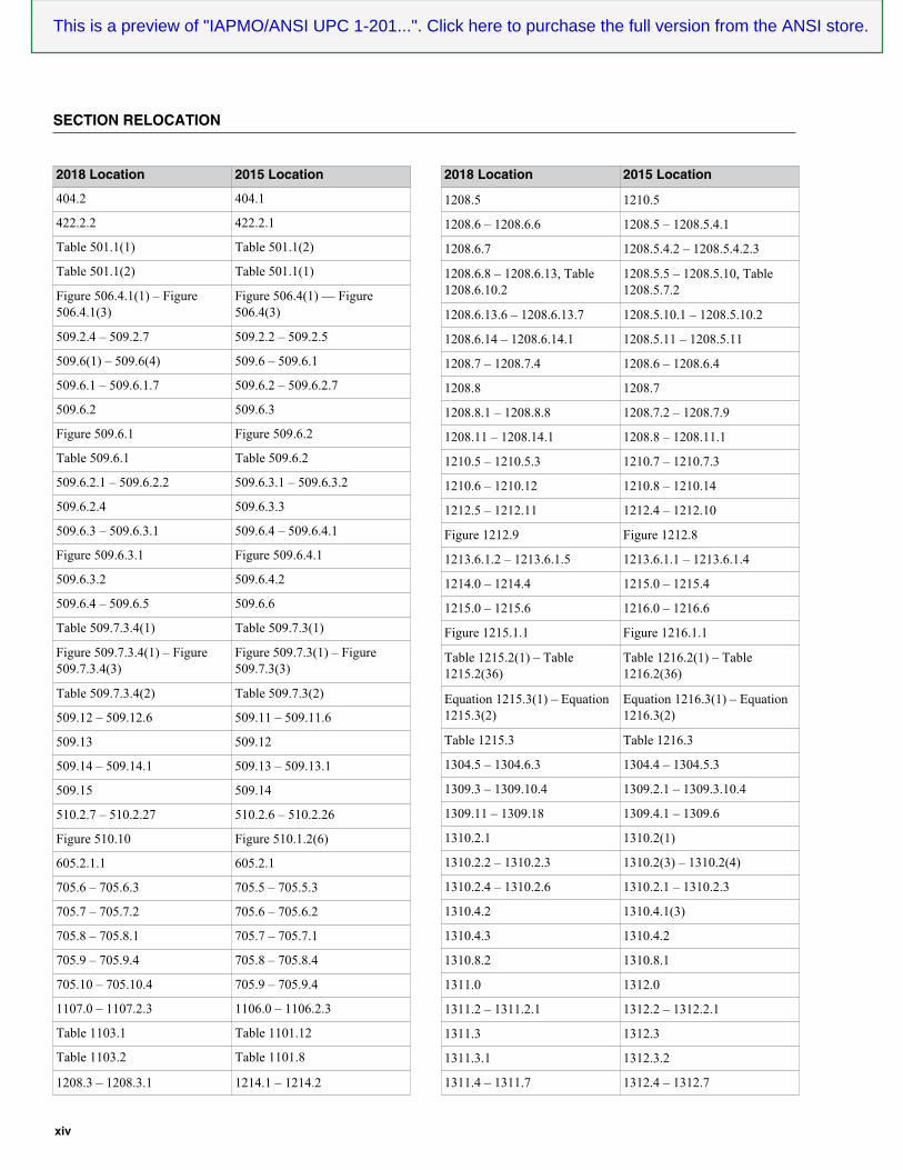
SECTION RELOCATION
2018 Location 2015 Location
404.2 404.1
422.2.2 422.2.1
Table 501.1(1) Table 501.1(2)
Table 501.1(2) Table 501.1(1)
Figure 506.4.1(1) – Figure506.4.1(3)
Figure 506.4(1) — Figure506.4(3)
509.2.4 – 509.2.7 509.2.2 – 509.2.5
509.6(1) – 509.6(4) 509.6 – 509.6.1
509.6.1 – 509.6.1.7 509.6.2 – 509.6.2.7
509.6.2 509.6.3
Figure 509.6.1 Figure 509.6.2
Table 509.6.1 Table 509.6.2
509.6.2.1 – 509.6.2.2 509.6.3.1 – 509.6.3.2
509.6.2.4 509.6.3.3
509.6.3 – 509.6.3.1 509.6.4 – 509.6.4.1
Figure 509.6.3.1 Figure 509.6.4.1
509.6.3.2 509.6.4.2
509.6.4 – 509.6.5 509.6.6
Table 509.7.3.4(1) Table 509.7.3(1)
Figure 509.7.3.4(1) – Figure509.7.3.4(3)
Figure 509.7.3(1) – Figure509.7.3(3)
Table 509.7.3.4(2) Table 509.7.3(2)
509.12 – 509.12.6 509.11 – 509.11.6
509.13 509.12
509.14 – 509.14.1 509.13 – 509.13.1
509.15 509.14
510.2.7 – 510.2.27 510.2.6 – 510.2.26
Figure 510.10 Figure 510.1.2(6)
605.2.1.1 605.2.1
705.6 – 705.6.3 705.5 – 705.5.3
705.7 – 705.7.2 705.6 – 705.6.2
705.8 – 705.8.1 705.7 – 705.7.1
705.9 – 705.9.4 705.8 – 705.8.4
705.10 – 705.10.4 705.9 – 705.9.4
1107.0 – 1107.2.3 1106.0 – 1106.2.3
Table 1103.1 Table 1101.12
Table 1103.2 Table 1101.8
1208.3 – 1208.3.1 1214.1 – 1214.2
2018 Location 2015 Location
1208.5 1210.5
1208.6 – 1208.6.6 1208.5 – 1208.5.4.1
1208.6.7 1208.5.4.2 – 1208.5.4.2.3
1208.6.8 – 1208.6.13, Table1208.6.10.2
1208.5.5 – 1208.5.10, Table1208.5.7.2
1208.6.13.6 – 1208.6.13.7 1208.5.10.1 – 1208.5.10.2
1208.6.14 – 1208.6.14.1 1208.5.11 – 1208.5.11
1208.7 – 1208.7.4 1208.6 – 1208.6.4
1208.8 1208.7
1208.8.1 – 1208.8.8 1208.7.2 – 1208.7.9
1208.11 – 1208.14.1 1208.8 – 1208.11.1
1210.5 – 1210.5.3 1210.7 – 1210.7.3
1210.6 – 1210.12 1210.8 – 1210.14
1212.5 – 1212.11 1212.4 – 1212.10
Figure 1212.9 Figure 1212.8
1213.6.1.2 – 1213.6.1.5 1213.6.1.1 – 1213.6.1.4
1214.0 – 1214.4 1215.0 – 1215.4
1215.0 – 1215.6 1216.0 – 1216.6
Figure 1215.1.1 Figure 1216.1.1
Table 1215.2(1) – Table1215.2(36)
Table 1216.2(1) – Table1216.2(36)
Equation 1215.3(1) – Equation1215.3(2)
Equation 1216.3(1) – Equation1216.3(2)
Table 1215.3 Table 1216.3
1304.5 – 1304.6.3 1304.4 – 1304.5.3
1309.3 – 1309.10.4 1309.2.1 – 1309.3.10.4
1309.11 – 1309.18 1309.4.1 – 1309.6
1310.2.1 1310.2(1)
1310.2.2 – 1310.2.3 1310.2(3) – 1310.2(4)
1310.2.4 – 1310.2.6 1310.2.1 – 1310.2.3
1310.4.2 1310.4.1(3)
1310.4.3 1310.4.2
1310.8.2 1310.8.1
1311.0 1312.0
1311.2 – 1311.2.1 1312.2 – 1312.2.1
1311.3 1312.3
1311.3.1 1312.3.2
1311.4 – 1311.7 1312.4 – 1312.7
This is a preview of "IAPMO/ANSI UPC 1-201...". Click here to purchase the full version from the ANSI store.

xv
SECTION RELOCATION
2018 Location 2015 Location
1311.8 1312.1.3, 1312.1.3.1
1311.9.1 1312.8.1
1311.10 – 1311.10.6 1312.9 – 1312.9.2
1312.0 – 1313.2.1 1313.0 – 1314.1.1
1313.2.2 1314.1.2, 1314.1.2.1
1313.4 1314.1.2.2
1313.5 – 1313.7 1314.1.3 – 1314.2
1313.7.2 1314.2.1
1314.0 – 1315.1 1315.0 – 1316.1
1315.2.2 1316.2.3
1315.3 1316.3
1316.0 – 1317.1 1317.0 – 1318.1
1317.1.1, 1317.3 1318.2
1317.4 1318.3
1318.0 – 1318.5.3 1319.0 – 1319.5.3
1318.8 –1318.8.6 1319.6 –1319.6.61318.9 – 1318.10.7 1319.7 – 1319.8.7
1318.12 – 1318.12.2 1319.9 – 1319.9.2
1318.14 – 1318.15 1319.10 – 1319.11
Table 1318.15 Table 1319.11
1318.16 – 1319.3 1319.12 – 1320.3
1501.9 – 1501.9.1 1501.10 – 1501.10.1
1501.10 1501.9
1502.0, 1502.1 1501.11
1502.2 – 1503.9.7, Table1503.4
1501.11.1 – 1502.9.7, Table1502.4
1504.0, 1504.1 1502.10
1504.2 1502.10.1
Table 1504.2 Table 1502.10
1504.3 – 1504.5.7 1502.10.2 – 1502.11.1.6
Table 1504.5.5 Table 1502.11
1504.6 – 1504.7.3 1502.11.2 – 1502.11.3.3
Table 1504.7.3 Table 1502.11.3
1504.8 – 1505.9 1502.12 – 1503.9
Figure 1505.9 Figure 1503.9
1505.10 – 1602.9.6 1503.10 – 1602.9.4
Table 1602.9.6 Table 1602.9.4
2018 Location 2015 Location
1603.0, 1603.1 1602.9.5
1603.2 – 1603.16 1602.9.5.1 – 1602.9.12
1604.0, 1604.1 1602.10
1604.2 – 1604.3 1602.10.1 – 1602.10.2
1605.0, 1605.1 1602.11
1605.2 – 1605.3.4 1602.11.1 – 1602.11.2.4
Table A 104.4(1) Table A 104.4
Table C 303.2 – Table C 303.3 Table C 303.1(1) – Table C303.1(2)
E 101.2 E 102.1
E 201.0, E 201.1 E 101.2
E 301.0 – E 301.1 E 201.0 – E 201.1
E 301.2 E 203.1
Table E 301.2(1) – Table E301.2(2)
Table E 203.1(1) – Table E203.1(2)
E 301.2.1 – E 301.2.2 E 206.1 – E 206.2
E 301.2.3 – E 301.3.2 E 202.1 – E 204.3
E 301.4 – E 301.4.1 E 207.1 – E 207.2
E 302.0, E 302.1 E 301.0, E 301.1
E 302.2 E 302.1
E 302.2.1 E 310.1
E 302.2.2 E 305.1
E 302.2.3 E 304.1
E 302.2.4 E 303.1
E 302.3-302.6 E 306.1-E 309.1
E 302.7 – E 302.7.2 E 311.1 – E311.3
E 302.8 E 312.1
E 402.2 – E 402.2.1 E 402.1.1 – E 402.1.2
E 402.3 E 403.1
E 402.4 – E 402.4.2 E 404.1 – E 404.3
E 403.1 E 406.1
E 403.2 E 407.0, E 407.1
Table E 403.2 Table E 407.1
E 403.3 – E 403.4 E 408.1 – E 408.2
E 403.5 E 409.0, E 409.1
E 403.6 – E 403.7 E 409.2 – E 409.3
E 403.8 – E 403.9 E 410.1 – E 410.4
E 403.10 E 411.0, E 411.1
This is a preview of "IAPMO/ANSI UPC 1-201...". Click here to purchase the full version from the ANSI store.

xvi
2018 Location 2015 Location
E 403.11 E 412.0, E 412.1
E 403.12 – E 403.13 E 412.2 – E 412.3
E 404.0 – E 406.4 E 413.0 – E 415.4
E 501.2 E 601.0, E601.1
E 501.2.1 E 602.0, E 602.1
E 501.2.2 E 604.0, E 604.1
E 501.2.3 E 611.0, E 611.1
E 501.2.4 E 614.0, E 614.1
E 501.2.5 E 615.0, E 615.1
E 501.3 E 603.0, E 603.1
E 501.3.1 E 608.0, E 608.1
E 501.3.2 E 609.0, E 609.1
E 501.3.3 E 610.0, E 610.1
E 501.4 E 606.0, E 606.1
E 501.5 E 607.0, E 607.1
E 501.6 E 605.0, E 605.1
E 501.7 E 612.0, E 612.1
E 501.7.1 E 613.0, E 613.1
E 501.8 E 803.0, E 803.1
E 502.0 – E 502.1 E 701.0 – E 701.1
E 502.2 E 702.0, E 702.1
E 502.3 E 703.0, E 703.1
E 502.4 E 704.0, E 704.1
E 502.5 E 705.0, E 705.1
E 502.6 E 706.0, E 706.1
E 502.7 E 707.0, E 707.1
E 503.0 – E 503.1 E 801.0 – E 801.1
E 503.2 E 802.0, E 802.1
E 504.0 – E 504.1 E 901.0 – E 901.1
E 504.2 E 904.0, E 904.1
E 504.3 E 902.0, E 902.1
E 504.4 E 903.0, E 903.1
Table E 504.4 Table E 903.1
E 504.5 E 905.0, E 905.1
E 504.6 E 1001.0, E 1001.1
E 504.6.1 E 1002.0, E 1002.1
E 504.6.2 E 1003.0, E 1003.1
2018 Location 2015 Location
E 505.0 – E 505.1 E 1101.0 – E 1101.1
E 505.2 E 1102.0, E 1102.1
E 505.3 E 1103.0, E 1103.1
E 505.4 E 1104.0, E 1104.1
E 506.0 – E 506.1 E 1201.0 – E 1201.1
Table H 201.1(2) – Table H201.1(3)
Table H 201.1(3) – Table H201.1(4)
Table H 201.1(4) Table H 201.1(2)
Table K 101.5.1 Table K 101.5
K 104.2 K 104.1.1
K 104.3 K 104.2
Table K 104.3(1) – Table K104.3(2)
Table K 104.2(1) – Table K104.2(2)
K 104.4 – K 104.6 K 104.2.1 – K 104.3
K 105.0, K 105.1 K 104.4
K 105.2 – K 105.12 K 104.4.1 – K 104.6
K 106.0, K 106.1 K 104.7
K 106.2 – K 106.4.4 K 104.7.1 – K 104.9.4
K 106.5 – K 106.7 K 104.11 – K 104.13
K 107.0 – K 107.1 K 105.0 – K 105.1
K 108.0 – K 108.1 K 106.0 – K 106.1
L 402.5.2 L 402.5.2.1, L 402.5.2.2
L 407.3 – L 407.4 L 407.2 – L 407.3
L 501.0 – L 502.7 L 601.0 – L 602.7
Table L 502.7 Table L 602.7
L 502.7.1 – L 502.7.3 L 602.7.1 – L 602.7.3
L 503.0 – L 503.4.5 L 603.0 – L 603.4.3.1
Table L 503.3.2 – Table L503.3.3
Table L 603.3.2 – Table L603.3.3
L 503.5 L 603.5
L 504.0 – L 506.1 L 604.1 – L 606.1
L 601.0 – L 602.1 L 701.0 – L 702.1
L 701.0 – L 701.2 L 801.9 – L 801.2
Table L 701.2(1) – Table L701.2(2)
Table L 801.2(1) – Table L801.2(2)
SECTION RELOCATION
This is a preview of "IAPMO/ANSI UPC 1-201...". Click here to purchase the full version from the ANSI store.

xvii2018 UNIFORM PLUMBING CODE
CHAPTER 1 ADMINISTRATION . . . . . . . . . . . . .1
101.0 General . . . . . . . . . . . . . . . . . . . . . . .1
101.1 Title . . . . . . . . . . . . . . . . . . . . . . . . . .1
101.2 Scope . . . . . . . . . . . . . . . . . . . . . . . .1
101.3 Purpose . . . . . . . . . . . . . . . . . . . . . .1
101.4 Unconstitutional . . . . . . . . . . . . . . . .1
101.5 Validity . . . . . . . . . . . . . . . . . . . . . . .1
102.0 Applicability . . . . . . . . . . . . . . . . . . . .1
102.1 Conflicts Between Codes . . . . . . . . .1
102.2 Existing Installations . . . . . . . . . . . . .1
102.3 Maintenance . . . . . . . . . . . . . . . . . . .1
102.4 Additions, Alterations,Renovations, or Repairs . . . . . . . . . .1
102.5 Health and Safety . . . . . . . . . . . . . . .1
102.6 Changes in Building Occupancy . . .1
102.7 Moved Structures . . . . . . . . . . . . . . .1
102.8 Appendices . . . . . . . . . . . . . . . . . . . .1
103.0 Duties and Powers of theAuthority Having Jurisdiction . . . . . .2
103.1 General . . . . . . . . . . . . . . . . . . . . . . .2
103.2 Liability . . . . . . . . . . . . . . . . . . . . . . .2
103.3 Applications and Permits . . . . . . . . .2
103.4 Right of Entry . . . . . . . . . . . . . . . . . .2
104.0 Permits . . . . . . . . . . . . . . . . . . . . . . .2
104.1 Permits Required . . . . . . . . . . . . . . .2
104.2 Exempt Work . . . . . . . . . . . . . . . . . .2
104.3 Application for Permit . . . . . . . . . . . .2
104.4 Permit Issuance . . . . . . . . . . . . . . . .3
104.5 Fees . . . . . . . . . . . . . . . . . . . . . . . . .4
105.0 Inspections and Testing . . . . . . . . . .4
105.1 General . . . . . . . . . . . . . . . . . . . . . . .4
105.2 Required Inspections . . . . . . . . . . . .4
105.3 Testing of Systems . . . . . . . . . . . . . .5
105.4 Connection to Service Utilities . . . . .5
106.0 Violations and Penalties . . . . . . . . . .5
106.1 General . . . . . . . . . . . . . . . . . . . . . . .5
106.2 Notices of Correction or Violation . . .5
106.3 Penalties . . . . . . . . . . . . . . . . . . . . . .5
106.4 Stop Orders . . . . . . . . . . . . . . . . . . .6
106.5 Authority to Disconnect Utilitiesin Emergencies . . . . . . . . . . . . . . . . .6
106.6 Authority to Condemn . . . . . . . . . . . .6
107.0 Board of Appeals . . . . . . . . . . . . . . .6
107.1 General . . . . . . . . . . . . . . . . . . . . . . .6
107.2 Limitations of Authority . . . . . . . . . . .6
Table 104.5 Plumbing Permit Fees . . . . . . . . . . .7
CHAPTER 2 DEFINITIONS . . . . . . . . . . . . . . . . . .9
201.0 General . . . . . . . . . . . . . . . . . . . . . . .9
201.1 Applicability . . . . . . . . . . . . . . . . . . . .9
202.0 Definition of Terms . . . . . . . . . . . . . .9
202.1 General . . . . . . . . . . . . . . . . . . . . . . .9
CHAPTER 3 GENERAL REGULATIONS . . . . . .21
301.0 General . . . . . . . . . . . . . . . . . . . . . .21
301.1 Applicability . . . . . . . . . . . . . . . . . . .21
301.2 Minimum Standards . . . . . . . . . . . .21
301.3 Alternate Materials and Methodsof Construction Equivalency . . . . . .21
301.4 Flood Hazard Areas . . . . . . . . . . . .21
301.5 Alternative Engineered Design . . . .22
302.0 Iron Pipe Size (IPS) Pipe . . . . . . . .22
302.1 General . . . . . . . . . . . . . . . . . . . . . .22
303.0 Disposal of Liquid Waste . . . . . . . .22
303.1 General . . . . . . . . . . . . . . . . . . . . . .22
304.0 Connections to PlumbingSystem Required . . . . . . . . . . . . . .22
304.1 General . . . . . . . . . . . . . . . . . . . . . .22
305.0 Damage to Drainage Systemor Public Sewer . . . . . . . . . . . . . . .22
305.1 Unlawful Practices . . . . . . . . . . . . .22
306.0 Industrial Wastes . . . . . . . . . . . . . .22
306.1 Detrimental Wastes . . . . . . . . . . . .22
306.2 Safe Discharge . . . . . . . . . . . . . . . .22
307.0 Location . . . . . . . . . . . . . . . . . . . . .22
307.1 System . . . . . . . . . . . . . . . . . . . . . .22
307.2 Ownership . . . . . . . . . . . . . . . . . . .23
308.0 Improper Location . . . . . . . . . . . . . .23
308.1 General . . . . . . . . . . . . . . . . . . . . . .23
309.0 Workmanship . . . . . . . . . . . . . . . . .23
309.1 Engineering Practices . . . . . . . . . . .23
309.2 Concealing Imperfections . . . . . . . .23
309.3 Burred Ends . . . . . . . . . . . . . . . . . .23
309.4 Installation Practices . . . . . . . . . . . .23
309.5 Sound Transmission . . . . . . . . . . . .23
310.0 Prohibited Fittings andPractices . . . . . . . . . . . . . . . . . . . . .23
310.1 Fittings . . . . . . . . . . . . . . . . . . . . . .23
TABLE OF CONTENTS
This is a preview of "IAPMO/ANSI UPC 1-201...". Click here to purchase the full version from the ANSI store.

310.2 Drainage and Vent Piping . . . . . . .23
310.3 Waste Connection . . . . . . . . . . . . .23
310.4 Use of Vent and Waste Pipes . . . .23
310.5 Obstruction of Flow . . . . . . . . . . . .23
310.6 Dissimilar Metals . . . . . . . . . . . . . .23
310.7 Direction of Flow . . . . . . . . . . . . . . .23
310.8 Screwed Fittings . . . . . . . . . . . . . . .23
311.0 Independent Systems . . . . . . . . . . .23
311.1 General . . . . . . . . . . . . . . . . . . . . . .23
312.0 Protection of Piping, Materials,and Structures . . . . . . . . . . . . . . . .23
312.1 General . . . . . . . . . . . . . . . . . . . . . .23
312.2 Installation . . . . . . . . . . . . . . . . . . .23
312.3 Building Sewer and DrainagePiping . . . . . . . . . . . . . . . . . . . . . . .24
312.4 Corrosion, Erosion, andMechanical Damage . . . . . . . . . . . .24
312.5 Protectively Coated Pipe . . . . . . . .24
312.6 Freezing Protection . . . . . . . . . . . .24
312.7 Fire-Resistant Construction . . . . . .24
312.8 Waterproofing of Openings . . . . . .24
312.9 Steel Nail Plates . . . . . . . . . . . . . . .24
312.10 Sleeves . . . . . . . . . . . . . . . . . . . . . .24
312.11 Structural Members . . . . . . . . . . . .24
312.12 Rodentproofing . . . . . . . . . . . . . . . .24
313.0 Hangers and Supports . . . . . . . . . .24
313.1 General . . . . . . . . . . . . . . . . . . . . . .24
313.2 Material . . . . . . . . . . . . . . . . . . . . . .24
313.3 Suspended Piping . . . . . . . . . . . . .24
313.4 Alignment . . . . . . . . . . . . . . . . . . . .24
313.5 Underground Installation . . . . . . . .24
313.6 Hanger Rod Sizes . . . . . . . . . . . . .24
Table 313.6 Hanger Rod Sizes . . . . . . . . . . . . .24
313.7 Gas Piping . . . . . . . . . . . . . . . . . . .24
314.0 Trenching, Excavation, andBackfill . . . . . . . . . . . . . . . . . . . . . .25
314.1 Trenches . . . . . . . . . . . . . . . . . . . . .25
314.2 Tunneling and Driving . . . . . . . . . .25
314.3 Open Trenches . . . . . . . . . . . . . . . .25
314.4 Excavations . . . . . . . . . . . . . . . . . .25
315.0 Joints and Connections . . . . . . . . .25
315.1 Unions . . . . . . . . . . . . . . . . . . . . . .25
315.2 Prohibited Joints andConnections . . . . . . . . . . . . . . . . . .25
316.0 Increasers and Reducers . . . . . . . .25
316.1 General . . . . . . . . . . . . . . . . . . . . . .25
317.0 Food-Handling Establishments . . . .25
317.1 General . . . . . . . . . . . . . . . . . . . . . .25
318.0 Test Gauges . . . . . . . . . . . . . . . . . .25
318.1 General . . . . . . . . . . . . . . . . . . . . . .25
318.2 Pressure Tests (10 psi or less) . . .25
318.3 Pressure Tests (greater than10 psi to 100 psi) . . . . . . . . . . . . . .25
318.4 Pressure Tests (exceeding100 psi) . . . . . . . . . . . . . . . . . . . . . .25
318.5 Pressure Range . . . . . . . . . . . . . . .26
319.0 Medical Gas and VacuumSystems . . . . . . . . . . . . . . . . . . . . .26
319.1 General . . . . . . . . . . . . . . . . . . . . . .26
320.0 Rehabilitation of Piping Systems . .26
320.1 General . . . . . . . . . . . . . . . . . . . . . .26
Table 313.3 Hangers and Supports . . . . . . . . . .26
CHAPTER 4 PLUMBING FIXTURESAND FIXTURE FITTINGS . . . . . . .27
401.0 General . . . . . . . . . . . . . . . . . . . . . .27
401.1 Applicability . . . . . . . . . . . . . . . . . . .27
401.2 Quality of Fixtures . . . . . . . . . . . . .27
402.0 Installation . . . . . . . . . . . . . . . . . . .27
402.1 Cleaning . . . . . . . . . . . . . . . . . . . . .27
402.2 Joints . . . . . . . . . . . . . . . . . . . . . . .27
402.3 Securing Fixtures . . . . . . . . . . . . . .27
402.4 Wall-Hung Fixtures . . . . . . . . . . . . .27
402.5 Setting . . . . . . . . . . . . . . . . . . . . . .27
402.6 Flanged Fixture Connections . . . . .27
402.7 Supply Fittings . . . . . . . . . . . . . . . .27
402.8 Installation . . . . . . . . . . . . . . . . . . .27
402.9 Design and Installation ofPlumbing Fixtures . . . . . . . . . . . . . .28
402.10 Slip Joint Connections . . . . . . . . . .28
402.11 Future Fixtures . . . . . . . . . . . . . . . .28
403.0 Accessible Plumbing Facilities . . . .28
403.1 General . . . . . . . . . . . . . . . . . . . . . .28
403.2 Fixtures and Fixture Fittingsfor Persons with Disabilities . . . . . .28
403.3 Exposed Pipes and Surfaces . . . . .28
404.0 Waste Fittings and Overflows . . . . .28
404.1 Waste Fittings . . . . . . . . . . . . . . . . .28
404.2 Overflows . . . . . . . . . . . . . . . . . . . .28
405.0 Prohibited Fixtures . . . . . . . . . . . . .28
405.1 Prohibited Water Closets . . . . . . . .28
405.2 Prohibited Urinals . . . . . . . . . . . . . .28
405.3 Miscellaneous Fixtures . . . . . . . . . .28
406.0 Special Fixtures and Specialties . .28
406.1 Water and Waste Connections . . . .28
406.2 Special Use Sinks . . . . . . . . . . . . .28
406.3 Special Use Fixtures . . . . . . . . . . .28
xviii 2018 UNIFORM PLUMBING CODE
This is a preview of "IAPMO/ANSI UPC 1-201...". Click here to purchase the full version from the ANSI store.

406.4 Zinc Alloy Components . . . . . . . . .28
407.0 Lavatories . . . . . . . . . . . . . . . . . . . .28
407.1 Application . . . . . . . . . . . . . . . . . . .28
407.2 Water Consumption . . . . . . . . . . . .28
407.3 Limitation of Hot WaterTemperature for PublicLavatories . . . . . . . . . . . . . . . . . . . .28
407.4 Transient Public Lavatories . . . . . .29
407.5 Waste Outlet . . . . . . . . . . . . . . . . . .29
407.6 Overflow . . . . . . . . . . . . . . . . . . . . .29
408.0 Showers . . . . . . . . . . . . . . . . . . . . .29
408.1 Application . . . . . . . . . . . . . . . . . . .29
408.2 Water Consumption . . . . . . . . . . . .29
408.3 Individual Shower andTub-Shower CombinationControl Valves . . . . . . . . . . . . . . . .29
408.4 Waste Outlet . . . . . . . . . . . . . . . . . .29
408.5 Finished Curb or Threshold . . . . . .29
408.6 Shower Compartments . . . . . . . . . .29
408.7 Lining for Showers andReceptors . . . . . . . . . . . . . . . . . . . .29
408.8 Public Shower Floors . . . . . . . . . . .30
408.9 Location of Valves and Heads . . . .30
408.10 Water Supply Riser . . . . . . . . . . . .30
409.0 Bathtubs and WhirlpoolBathtubs . . . . . . . . . . . . . . . . . . . . .30
409.1 Application . . . . . . . . . . . . . . . . . . .30
409.2 Waste Outlet . . . . . . . . . . . . . . . . . .30
409.3 Overflow . . . . . . . . . . . . . . . . . . . . .30
409.4 Limitation of Hot Water inBathtubs and WhirlpoolBathtubs . . . . . . . . . . . . . . . . . . . . .30
409.5 Backflow Protection . . . . . . . . . . . .30
409.6 Installation and Access . . . . . . . . . .31
410.0 Bidets . . . . . . . . . . . . . . . . . . . . . . .31
410.1 Application . . . . . . . . . . . . . . . . . . .31
410.2 Backflow Protection . . . . . . . . . . . .31
410.3 Limitation of WaterTemperature in Bidets . . . . . . . . . .31
411.0 Water Closets . . . . . . . . . . . . . . . . .31
411.1 Application . . . . . . . . . . . . . . . . . . .31
411.2 Water Consumption . . . . . . . . . . . .31
411.3 Water Closet Seats . . . . . . . . . . . .31
411.4 Personal Hygiene Devices . . . . . . .31
412.0 Urinals . . . . . . . . . . . . . . . . . . . . . .31
412.1 Application . . . . . . . . . . . . . . . . . . .31
412.2 Backflow Protection . . . . . . . . . . . .31
413.0 Flushing Devices . . . . . . . . . . . . . .31
413.1 Where Required . . . . . . . . . . . . . . .31
413.2 Flushometer Valves . . . . . . . . . . . .31
413.3 Flush Tanks . . . . . . . . . . . . . . . . . .32
413.4 Water Supply for Flush Tanks . . . .32
413.5 Overflows in Flush Tanks . . . . . . . .32
414.0 Dishwashing Machines . . . . . . . . . .32
414.1 Application . . . . . . . . . . . . . . . . . . .32
414.2 Backflow Protection . . . . . . . . . . . .32
414.3 Drainage Connection . . . . . . . . . . .32
415.0 Drinking Fountains . . . . . . . . . . . . .32
415.1 Application . . . . . . . . . . . . . . . . . . .32
415.2 Drinking Fountain Alternatives . . . .32
415.3 Drainage Connection . . . . . . . . . . .32
415.4 Location . . . . . . . . . . . . . . . . . . . . .32
416.0 Emergency Eyewash andShower Equipment . . . . . . . . . . . . .32
416.1 Application . . . . . . . . . . . . . . . . . . .32
416.2 Water Supply . . . . . . . . . . . . . . . . .32
416.3 Installation . . . . . . . . . . . . . . . . . . .32
416.4 Location . . . . . . . . . . . . . . . . . . . . .32
416.5 Drain . . . . . . . . . . . . . . . . . . . . . . . .32
417.0 Faucets and Fixture Fittings . . . . . .32
417.1 Application . . . . . . . . . . . . . . . . . . .32
417.2 Deck Mounted Bath/ShowerValves . . . . . . . . . . . . . . . . . . . . . . .32
417.3 Handheld Showers . . . . . . . . . . . . .32
417.4 Faucets and Fixture Fittingswith Hose Connected Outlets . . . . .32
417.5 Separate Controls for Hotand Cold Water . . . . . . . . . . . . . . .32
418.0 Floor Drains . . . . . . . . . . . . . . . . . .33
418.1 Application . . . . . . . . . . . . . . . . . . .33
418.2 Strainer . . . . . . . . . . . . . . . . . . . . . .33
418.3 Location of Floor Drains . . . . . . . . .33
418.4 Food Storage Areas . . . . . . . . . . . .33
418.5 Floor Slope . . . . . . . . . . . . . . . . . . .33
419.0 Food Waste Disposers . . . . . . . . . .33
419.1 Application . . . . . . . . . . . . . . . . . . .33
419.2 Drainage Connection . . . . . . . . . . .33
419.3 Water Supply . . . . . . . . . . . . . . . . .33
420.0 Sinks . . . . . . . . . . . . . . . . . . . . . . . .33
420.1 Application . . . . . . . . . . . . . . . . . . .33
420.2 Water Consumption . . . . . . . . . . . .33
420.3 Pre-Rinse Spray Valve . . . . . . . . . .33
420.4 Waste Outlet . . . . . . . . . . . . . . . . . .33
421.0 Floor Sinks . . . . . . . . . . . . . . . . . . .33
421.1 Application . . . . . . . . . . . . . . . . . . .33
421.2 Strainers . . . . . . . . . . . . . . . . . . . . .33
422.0 Minimum Number ofRequired Fixtures . . . . . . . . . . . . . .33
xix2018 UNIFORM PLUMBING CODE
This is a preview of "IAPMO/ANSI UPC 1-201...". Click here to purchase the full version from the ANSI store.

422.1 Fixture Count . . . . . . . . . . . . . . . . .33
422.2 Separate Facilities . . . . . . . . . . . . .34
422.3 Fixture Requirements forSpecial Occupancies . . . . . . . . . . .34
422.4 Toilet Facilities ServingEmployees and Customers . . . . . .34
422.5 Toilet Facilities for Workers . . . . . .34
Table 422.1 Minimum Plumbing Facilities . . . . .35
CHAPTER 5 WATER HEATERS . . . . . . . . . . . .41
501.0 General . . . . . . . . . . . . . . . . . . . . . .41
501.1 Applicability . . . . . . . . . . . . . . . . . . .41
Table 501.1(1) Water Heaters . . . . . . . . . . . . . . . .41
502.0 Permits . . . . . . . . . . . . . . . . . . . . . .41
502.1 General . . . . . . . . . . . . . . . . . . . . . .41
503.0 Inspection . . . . . . . . . . . . . . . . . . . .41
503.1 Inspection of Chimneys or Vents . .41
503.2 Final Water Heater Inspection . . . .41
504.0 Water Heater Requirements . . . . . .41
504.1 Location . . . . . . . . . . . . . . . . . . . . .41
504.2 Vent . . . . . . . . . . . . . . . . . . . . . . . .41
Table 501.1(2) First Hour Rating . . . . . . . . . . . . . .41
504.3 Clearance . . . . . . . . . . . . . . . . . . . .42
504.4 Pressure-Limiting Devices . . . . . . .42
504.5 Temperature-Limiting Devices . . . .42
504.6 Temperature, Pressure, andVacuum Relief Devices . . . . . . . . .42
505.0 Oil-Burning and Other WaterHeaters . . . . . . . . . . . . . . . . . . . . . .42
505.1 Water Heaters . . . . . . . . . . . . . . . .42
505.2 Safety Devices . . . . . . . . . . . . . . . .42
505.3 Oil-Fired Water Heaters . . . . . . . . .42
505.4 Indirect-Fired Water Heaters . . . . .42
506.0 Air for Combustion andVentilation . . . . . . . . . . . . . . . . . . . .42
506.1 General . . . . . . . . . . . . . . . . . . . . . .42
506.2 Indoor Combustion Air . . . . . . . . . .43
506.3 Indoor Opening Size andLocation . . . . . . . . . . . . . . . . . . . . .43
506.4 Outdoor Combustion Air . . . . . . . . .43
506.5 Combination Indoor andOutdoor Combustion Air . . . . . . . . .45
506.6 Engineered Installations . . . . . . . . .45
506.7 Mechanical Combustion AirSupply . . . . . . . . . . . . . . . . . . . . . . .45
506.8 Louvers, Grilles, and Screens . . . .45
506.9 Combustion Air Ducts . . . . . . . . . . .45
507.0 Appliance and EquipmentInstallation Requirements . . . . . . . .46
507.1 Dielectric Insulator . . . . . . . . . . . . .46
507.2 Seismic Provisions . . . . . . . . . . . . .46
507.3 Appliance Support . . . . . . . . . . . . .46
507.4 Ground Support . . . . . . . . . . . . . . .46
507.5 Drainage Pan . . . . . . . . . . . . . . . . .46
507.6 Added or ConvertedEquipment or Appliances . . . . . . . .46
507.7 Types of Gases . . . . . . . . . . . . . . .46
507.8 Safety Shutoff Devices forUnlisted LP-Gas ApplianceUsed Indoors . . . . . . . . . . . . . . . . .46
507.9 Use of Air or Oxygen UnderPressure . . . . . . . . . . . . . . . . . . . . .46
507.10 Protection of Gas Appliancesfrom Fumes or Gases otherthan Products of Combustion . . . . .46
507.11 Process Air . . . . . . . . . . . . . . . . . . .46
507.12 Flammable Vapors . . . . . . . . . . . . .46
507.13 Installation in ResidentialGarages . . . . . . . . . . . . . . . . . . . . .46
507.14 Installation in CommercialGarages . . . . . . . . . . . . . . . . . . . . .47
507.15 Installation in Aircraft Hangars . . . .47
507.16 Venting of Flue Gases . . . . . . . . . .47
507.17 Extra Device or Attachment . . . . . .47
507.18 Adequate Capacity of Piping . . . . .47
507.19 Avoiding Strain on Gas Piping . . . .47
507.20 Gas Appliance PressureRegulators . . . . . . . . . . . . . . . . . . .47
507.21 Venting of Gas AppliancePressure Regulators . . . . . . . . . . . .47
507.22 Bleed Lines for Diaphragm-TypeValves . . . . . . . . . . . . . . . . . . . . . . .47
507.23 Combination of Appliancesand Equipment . . . . . . . . . . . . . . . .47
507.24 Installation Instructions . . . . . . . . . .47
507.25 Protection of OutdoorAppliances . . . . . . . . . . . . . . . . . . .48
507.26 Accessibility for Service . . . . . . . . .48
507.27 Clearance to CombustibleMaterials . . . . . . . . . . . . . . . . . . . . .48
508.0 Appliances on Roofs . . . . . . . . . . .48
508.1 General . . . . . . . . . . . . . . . . . . . . . .48
508.2 Installation of Applianceson Roofs . . . . . . . . . . . . . . . . . . . . .48
508.3 Appliances on Roofs . . . . . . . . . . .48
508.4 Appliances in Attics andUnder-Floor Spaces . . . . . . . . . . . .48
509.0 Venting of Appliances . . . . . . . . . . .49
509.1 Listing . . . . . . . . . . . . . . . . . . . . . . .49
509.2 Connection to Venting Systems . . .49
xx 2018 UNIFORM PLUMBING CODE
This is a preview of "IAPMO/ANSI UPC 1-201...". Click here to purchase the full version from the ANSI store.

509.3 Design and Construction . . . . . . . .49
509.4 Type of Venting System tobe Used . . . . . . . . . . . . . . . . . . . . .50
Table 509.4 Type of Venting System tobe Used . . . . . . . . . . . . . . . . . . . . .50
509.5 Masonry, Metal, andFactory-Built Chimneys . . . . . . . . .50
509.6 Gas Vents . . . . . . . . . . . . . . . . . . . .52
Table 509.6.1 Roof Slope Heights . . . . . . . . . . . .53
509.7 Single-Wall Metal Pipe . . . . . . . . . .55
Table 509.7.3.4(1) Clearance for Connectors . . . . . . .55
Table 509.7.3.4(2) Reduction of Clearances withSpecified Forms of Protection . . . .57
509.8 Through-the-Wall VentTermination . . . . . . . . . . . . . . . . . . .58
509.9 Condensation Drain . . . . . . . . . . . .59
509.10 Vent Connectors forCategory I Appliances . . . . . . . . . .59
Table 509.10.1.3 Minimum Thickness forGalvanized Steel VentConnectors for Low-HeatAppliances . . . . . . . . . . . . . . . . . . .60
Table 509.10.1.4 Minimum Thickness for SteelVent Connectors forMedium-Heat Appliances . . . . . . . .60
509.11 Vent Connectors for Category II,Category III, and Category IVAppliances . . . . . . . . . . . . . . . . . . .61
509.12 Draft Hoods and Draft Controls . . .61
509.13 Manually Operated Dampers . . . . .62
509.14 Automatically OperatedVent Dampers . . . . . . . . . . . . . . . . .62
509.15 Obstructions . . . . . . . . . . . . . . . . . .62
510.0 Sizing of Category I VentingSystems . . . . . . . . . . . . . . . . . . . . .62
510.1 Single Appliance Vent Table510.1.2(1) throughTable 510.1.2(6) . . . . . . . . . . . . . . .62
510.2 Multiple Appliance Vent Table510.2(1) through Table 510.2(9) . . .63
Table 510.2.1 Vent Connector MaximumLength . . . . . . . . . . . . . . . . . . . . . . .64
Table 510.1.2(1) Type B Double-Wall Gas Vent . . . .68
Table 510.1.2(2) Type B Double-Wall Gas Vent . . . .71
Table 510.1.2(3) Masonry Chimney . . . . . . . . . . . . . .73
Table 510.1.2(4) Masonry Chimney . . . . . . . . . . . . . .75
Table 510.1.2(5) Single-Wall Metal Pipe orType B Asbestos-Cement Vent . . .77
Table 510.1.2(6) Exterior Masonry Chimney . . . . . . .78
Table 510.2(1) Type B Double-Wall Vent . . . . . . . .79
Table 510.2(2) Type B Double-Wall Vent . . . . . . . .83
Table 510.2(3) Masonry Chimney . . . . . . . . . . . . . .85
Table 510.2(4) Masonry Chimney . . . . . . . . . . . . . .87
Table 510.2(5) Single-Wall Metal Pipe orType B Asbestos-Cement Vent . . .89
Table 510.2(6) Exterior Masonry Chimney . . . . . . .89
Table 510.2(7) Exterior Masonry Chimney . . . . . . .90
Table 510.2(8) Exterior Masonry Chimney . . . . . . .91
Table 510.2(9) Exterior Masonry Chimney . . . . . . .92
CHAPTER 6 WATER SUPPLY ANDDISTRIBUTION . . . . . . . . . . . . . . .93
601.0 General . . . . . . . . . . . . . . . . . . . . . .93
601.1 Applicability . . . . . . . . . . . . . . . . . . .93
601.2 Hot and Cold Water Required . . . .93
601.3 Identification of a Potable andNonpotable Water System . . . . . . .93
Table 601.3.2 Minimum Length of ColorField and Size of Letters . . . . . . . .93
602.0 Unlawful Connections . . . . . . . . . . .93
602.1 Prohibited Installation . . . . . . . . . . .93
602.2 Cross-Contamination . . . . . . . . . . .93
602.3 Backflow Prevention . . . . . . . . . . . .94
602.4 Approval by Authority . . . . . . . . . . .94
603.0 Cross-Connection Control . . . . . . .94
603.1 General . . . . . . . . . . . . . . . . . . . . . .94
603.2 Approval of Devices orAssemblies . . . . . . . . . . . . . . . . . . .94
603.3 Backflow Prevention Devices,Assemblies, and Methods . . . . . . .94
603.4 General Requirements . . . . . . . . . .94
Table 603.2 Backflow Prevention Devices,Assemblies, and Methods . . . . . . .95
Table 603.3.1 Minimum Air Gaps for WaterDistribution . . . . . . . . . . . . . . . . . . .97
603.5 Specific Requirements . . . . . . . . . .97
604.0 Materials . . . . . . . . . . . . . . . . . . . .100
604.1 Pipe, Tube, and Fittings . . . . . . . .100
604.2 Lead Content . . . . . . . . . . . . . . . .100
604.3 Copper or Copper Alloy Tube . . .100
604.4 Hard-Drawn Copper or CopperAlloy Tubing . . . . . . . . . . . . . . . . .100
604.5 Flexible Connectors . . . . . . . . . . .100
604.6 Cast-Iron Fittings . . . . . . . . . . . . .100
604.7 Malleable Iron Fittings . . . . . . . . .100
604.8 Previously Used Piping andTubing . . . . . . . . . . . . . . . . . . . . . .100
604.9 Epoxy Coating . . . . . . . . . . . . . . .100
604.10 Plastic Materials . . . . . . . . . . . . . .100
604.11 Solder . . . . . . . . . . . . . . . . . . . . . .100
xxi2018 UNIFORM PLUMBING CODE
This is a preview of "IAPMO/ANSI UPC 1-201...". Click here to purchase the full version from the ANSI store.

604.12 Flexible Corrugated Connectors . .100
Table 604.1 Materials for Building Supplyand Water Distribution Pipingand Fittings . . . . . . . . . . . . . . . . . .101
604.13 Water Heater Connectors . . . . . . .101
605.0 Joints and Connections . . . . . . . .101
605.1 Copper or Copper Alloy Pipe,Tubing, and Joints . . . . . . . . . . . .101
605.2 CPVC Plastic Pipe and Joints . . .102
605.3 CPVC/AL/CPVC Plastic Pipeand Joints . . . . . . . . . . . . . . . . . . .103
605.4 Ductile Iron Pipe and Joints . . . . .103
605.5 Galvanized Steel Pipe andJoints . . . . . . . . . . . . . . . . . . . . . .103
605.6 PE Plastic Pipe/Tubing andJoints . . . . . . . . . . . . . . . . . . . . . .103
605.7 PE-AL-PE Plastic Pipe/Tubingand Joints . . . . . . . . . . . . . . . . . . .104
605.8 PE-RT . . . . . . . . . . . . . . . . . . . . . .104
605.9 PEX Plastic Tubing and Joints . . .104
605.10 PEX-AL-PEX Plastic Tubingand Joints . . . . . . . . . . . . . . . . . . .104
605.11 Polypropylene (PP) Pipingand Joints . . . . . . . . . . . . . . . . . . .104
605.12 PVC Plastic Pipe and Joints . . . . .105
605.13 Stainless Steel Pipe and Joints . .105
605.14 Slip Joints . . . . . . . . . . . . . . . . . . .105
605.15 Dielectric Unions . . . . . . . . . . . . . .105
605.16 Joints Between VariousMaterials . . . . . . . . . . . . . . . . . . . .105
606.0 Valves . . . . . . . . . . . . . . . . . . . . . .105
606.1 General . . . . . . . . . . . . . . . . . . . . .105
606.2 Fullway Valve . . . . . . . . . . . . . . . .106
606.3 Multidwelling Units . . . . . . . . . . . .106
606.4 Multiple Openings . . . . . . . . . . . . .106
606.5 Control Valve . . . . . . . . . . . . . . . .106
606.6 Accessible . . . . . . . . . . . . . . . . . .106
606.7 Multiple Fixtures . . . . . . . . . . . . . .106
607.0 Potable Water Supply Tanks . . . .106
607.1 General . . . . . . . . . . . . . . . . . . . . .106
607.2 Potable Water Tanks . . . . . . . . . .106
607.3 Venting . . . . . . . . . . . . . . . . . . . . .106
607.4 Overflow . . . . . . . . . . . . . . . . . . . .106
607.5 Valves . . . . . . . . . . . . . . . . . . . . . .106
608.0 Water Pressure, PressureRegulators, Pressure ReliefValves, and Vacuum ReliefValves . . . . . . . . . . . . . . . . . . . . . .106
608.1 Inadequate Water Pressure . . . . .106
608.2 Excessive Water Pressure . . . . . .106
608.3 Expansion Tanks, andCombination Temperatureand Pressure-Relief Valves . . . . .106
608.4 Pressure Relief Valves . . . . . . . . .107
608.5 Discharge Piping . . . . . . . . . . . . .107
608.6 Water-Heating Devices . . . . . . . . .107
608.7 Vacuum Relief Valves . . . . . . . . .107
609.0 Installation, Testing, Unions,and Location . . . . . . . . . . . . . . . . .107
609.1 Installation . . . . . . . . . . . . . . . . . .107
609.2 Trenches . . . . . . . . . . . . . . . . . . . .107
609.3 Under Concrete Slab . . . . . . . . . .107
609.4 Testing . . . . . . . . . . . . . . . . . . . . .107
609.5 Unions . . . . . . . . . . . . . . . . . . . . .107
609.6 Location . . . . . . . . . . . . . . . . . . . .108
609.7 Abutting Lot . . . . . . . . . . . . . . . . .108
609.8 Low-Pressure Cutoff Requiredon Booster Pumps for WaterDistribution Systems . . . . . . . . . . .108
609.9 Disinfection of Potable WaterSystem . . . . . . . . . . . . . . . . . . . . .108
609.10 Water Hammer . . . . . . . . . . . . . . .108
609.11 Pipe Insulation . . . . . . . . . . . . . . .108
610.0 Size of Potable Water Piping . . . .108
610.1 Size . . . . . . . . . . . . . . . . . . . . . . . .108
610.2 Pressure Loss . . . . . . . . . . . . . . . .108
610.3 Quantity of Water . . . . . . . . . . . . .109
610.4 Sizing Water Supply andDistribution Systems . . . . . . . . . . .109
610.5 Sizing per AppendicesA and C . . . . . . . . . . . . . . . . . . . .109
610.6 Friction and Pressure Loss . . . . . .109
610.7 Conditions for UsingTable 610.4 . . . . . . . . . . . . . . . . . .109
610.8 Size of Meter and BuildingSupply Pipe Using Table 610.4 . .109
610.9 Size of Branches . . . . . . . . . . . . .109
610.10 Sizing for Flushometer Valves . . .109
Table 610.10 Flushometer Fixture Unitsfor Water Sizing UsingTable 610.3 . . . . . . . . . . . . . . . . . .109
610.11 Sizing Systems forFlushometer Tanks . . . . . . . . . . . .110
610.12 Sizing for Velocity . . . . . . . . . . . . .110
610.13 Exceptions . . . . . . . . . . . . . . . . . .110
611.0 Drinking Water TreatmentUnits . . . . . . . . . . . . . . . . . . . . . . .110
611.1 Application . . . . . . . . . . . . . . . . . .110
611.2 Air Gap Discharge . . . . . . . . . . . .110
611.3 Connection Tubing . . . . . . . . . . . .110
xxii 2018 UNIFORM PLUMBING CODE
This is a preview of "IAPMO/ANSI UPC 1-201...". Click here to purchase the full version from the ANSI store.

611.4 Sizing of Residential Softeners . .110
612.0 Residential Fire SprinklerSystems . . . . . . . . . . . . . . . . . . . .110
612.1 Where Required . . . . . . . . . . . . . .110
Table 610.3 Water Supply Fixture Units(WSFU) and Minimum FixtureBranch Pipe Sizes . . . . . . . . . . . .111
Table 610.4 Fixture Unit Table forDetermining Water Pipe andMeter Sizes . . . . . . . . . . . . . . . . . .112
Table 611.4 Sizing of Residential WaterSofteners . . . . . . . . . . . . . . . . . . .113
612.2 Types of Systems . . . . . . . . . . . . .113
612.3 Sprinklers . . . . . . . . . . . . . . . . . . .113
Table 612.3.3.1 Locations Where IntermediateTemperature Sprinklersare Required . . . . . . . . . . . . . . . . .114
612.4 Sprinkler Piping System . . . . . . . .114
612.5 Sprinkler Piping Design . . . . . . . .114
Table 612.3.6 Minimum Separation FromObstruction . . . . . . . . . . . . . . . . . .115
Table 612.5.3.2(1) Water Service PressureLoss (PLws) . . . . . . . . . . . . . . . . .117
Table 612.5.3.2(2) Minimum Water MeterPressure Loss (PLm) . . . . . . . . . .118
612.6 Instructions and Signs . . . . . . . . .118
612.7 Inspection and Testing . . . . . . . . .118
Table 612.5.3.2(3) Elevation Loss (PLe) . . . . . . . . . .118
Table 612.5.3.2(4) Allowable Pipe Length for3⁄4 Inch Type M CopperWater Tubing . . . . . . . . . . . . . . . .119
Table 612.5.3.2(5) Allowable Pipe Length for1 Inch Type M CopperWater Tubing . . . . . . . . . . . . . . . .120
Table 612.5.3.2(6) Allowable Pipe Length for3⁄4 Inch IPS CPVC Pipe . . . . . . . .121
Table 612.5.3.2(7) Allowable Pipe Length for1 Inch IPS CPVC Pipe . . . . . . . . .122
Table 612.5.3.2(8) Allowable Pipe Length for3⁄4 Inch PEX Tubing . . . . . . . . . . .123
Table 612.5.3.2(9) Allowable Pipe Length for1 Inch PEX Tubing . . . . . . . . . . . .124
CHAPTER 7 SANITARY DRAINAGE . . . . . . . .125
PART I Drainage Systems . . . . . . . . . . .125
701.0 General . . . . . . . . . . . . . . . . . . . . .125
701.1 Applicability . . . . . . . . . . . . . . . . . .125
701.2 Drainage Piping . . . . . . . . . . . . . .125
701.3 Drainage Fittings . . . . . . . . . . . . .125
701.4 Continuous Wastes . . . . . . . . . . .125
701.5 Lead . . . . . . . . . . . . . . . . . . . . . . .125
701.6 Caulking Ferrules . . . . . . . . . . . . .125
701.7 Soldering Bushings . . . . . . . . . . . .125
Table 701.6 Caulking Ferrules . . . . . . . . . . . . .125
Table 701.7 Soldering Bushings . . . . . . . . . . . .125
702.0 Fixture Unit Equivalents . . . . . . . .125
702.1 Trap Size . . . . . . . . . . . . . . . . . . .125
702.2 Intermittent Flow . . . . . . . . . . . . . .125
Table 701.2 Materials for Drain, Waste,Vent Pipe and Fittings . . . . . . . . .126
Table 702.1 Drainage Fixture UnitValues (DFU) . . . . . . . . . . . . . . . .127
702.3 Continuous Flow . . . . . . . . . . . . . .128
Table 702.2(1) Maximum Drainage FixtureUnits for a Trap and Trap Arm . . .128
Table 702.2(2) Discharge Capacity in GallonsPer Minute for IntermittentFlow Only . . . . . . . . . . . . . . . . . . .128
703.0 Size of Drainage Piping . . . . . . . .128
703.1 Minimum Size . . . . . . . . . . . . . . . .128
703.2 Maximum Number of FixtureUnits . . . . . . . . . . . . . . . . . . . . . . .128
703.3 Sizing per Appendix C . . . . . . . . .128
704.0 Fixture Connections (Drainage) . .128
704.1 Inlet Fittings . . . . . . . . . . . . . . . . .128
704.2 Single Vertical Drainage Pipe . . . .128
704.3 Commercial Sinks . . . . . . . . . . . . .128
705.0 Joints and Connections . . . . . . . .128
705.1 ABS and ABS Co-ExtrudedPlastic Pipe and Joints . . . . . . . . .128
705.2 Cast-Iron Pipe and Joints . . . . . . .128
Table 703.2 Maximum Unit Loading andMaximum Length of Drainageand Vent Piping . . . . . . . . . . . . . .129
705.3 Copper or Copper Alloy Pipe(DWV) and Joints . . . . . . . . . . . . .129
705.4 Galvanized Steel Pipeand Joints . . . . . . . . . . . . . . . . . . .130
705.5 Polyethylene (PE) Sewer Pipe . . .130
705.6 PVC and PVC Co-ExtrudedPlastic Pipe and JoiningMethods . . . . . . . . . . . . . . . . . . . .130
705.7 Stainless Steel Pipe and Joints . .130
705.8 Vitrified Clay Pipe and Joints . . . .131
705.9 Special Joints . . . . . . . . . . . . . . . .131
705.10 Joints Between VariousMaterials . . . . . . . . . . . . . . . . . . . .131
706.0 Changes in Direction ofDrainage Flow . . . . . . . . . . . . . . .131
706.1 Approved Fittings . . . . . . . . . . . . .131
706.2 Horizontal to Vertical . . . . . . . . . .131
706.3 Horizontal to Horizontal . . . . . . . .131
xxiii2018 UNIFORM PLUMBING CODE
This is a preview of "IAPMO/ANSI UPC 1-201...". Click here to purchase the full version from the ANSI store.

706.4 Vertical to Horizontal . . . . . . . . . .131
707.0 Cleanouts . . . . . . . . . . . . . . . . . . .131
707.1 Plug . . . . . . . . . . . . . . . . . . . . . . .131
Table 707.1 Cleanouts . . . . . . . . . . . . . . . . . . .132
707.2 Approved . . . . . . . . . . . . . . . . . . .132
707.3 Watertight and Gastight . . . . . . . .132
707.4 Location . . . . . . . . . . . . . . . . . . . .132
707.5 Cleaning . . . . . . . . . . . . . . . . . . . .132
707.6 Extension . . . . . . . . . . . . . . . . . . .132
707.7 Interceptor . . . . . . . . . . . . . . . . . .132
707.8 Access . . . . . . . . . . . . . . . . . . . . .132
707.9 Clearance . . . . . . . . . . . . . . . . . . .132
707.10 Fittings . . . . . . . . . . . . . . . . . . . . .132
707.11 Pressure Drainage Systems . . . . .132
707.12 Countersunk Cleanout Plugs . . . .132
707.13 Hubless Blind Plugs . . . . . . . . . . .132
707.14 Trap Arms . . . . . . . . . . . . . . . . . . .132
708.0 Grade of Horizontal DrainagePiping . . . . . . . . . . . . . . . . . . . . . .132
708.1 General . . . . . . . . . . . . . . . . . . . . .132
709.0 Gravity Drainage Required . . . . . .132
709.1 General . . . . . . . . . . . . . . . . . . . . .132
710.0 Drainage of Fixtures LocatedBelow the Next UpstreamManhole or Below the MainSewer Level . . . . . . . . . . . . . . . . .132
710.1 Backflow Protection . . . . . . . . . . .132
710.2 Sewage Discharge . . . . . . . . . . . .133
710.3 Sewage Ejector and Pumps . . . . .133
710.4 Discharge Line . . . . . . . . . . . . . . .133
710.5 Size of Building Drains andSewers . . . . . . . . . . . . . . . . . . . . .133
710.6 Backwater Valves . . . . . . . . . . . . .133
710.7 Drainage and Venting Systems . .133
710.8 Sump and Receiving TankConstruction . . . . . . . . . . . . . . . . .133
710.9 Alarm . . . . . . . . . . . . . . . . . . . . . .133
710.10 Sump and Receiving TankCovers and Vents . . . . . . . . . . . . .133
710.11 Air Tanks . . . . . . . . . . . . . . . . . . .133
710.12 Grinder Pump Ejector . . . . . . . . . .133
710.13 Macerating Toilet Systemsand Pumped Waste Systems . . . .134
711.0 Suds Relief . . . . . . . . . . . . . . . . . .134
711.1 General . . . . . . . . . . . . . . . . . . . . .134
712.0 Testing . . . . . . . . . . . . . . . . . . . . .134
712.1 Media . . . . . . . . . . . . . . . . . . . . . .134
712.2 Water Test . . . . . . . . . . . . . . . . . .134
712.3 Air Test . . . . . . . . . . . . . . . . . . . . .134
PART II Building Sewers . . . . . . . . . . . . .134
713.0 Sewer Required . . . . . . . . . . . . . .134
713.1 Where Required . . . . . . . . . . . . . .134
713.2 Private Sewage DisposalSystem . . . . . . . . . . . . . . . . . . . . .134
713.3 Public Sewer . . . . . . . . . . . . . . . . .134
713.4 Public Sewer Availability . . . . . . .134
713.5 Permit . . . . . . . . . . . . . . . . . . . . . .134
713.6 Lot . . . . . . . . . . . . . . . . . . . . . . . . .134
713.7 Installation . . . . . . . . . . . . . . . . . .135
714.0 Damage to Public Sewer orPrivate Sewage DisposalSystem . . . . . . . . . . . . . . . . . . . . .135
714.1 Unlawful Practices . . . . . . . . . . . .135
714.2 Prohibited Water Discharge . . . . .135
714.3 Prohibited Sewer Connection . . . .135
714.4 Commercial Food WasteDisposer . . . . . . . . . . . . . . . . . . . .135
714.5 Tanks . . . . . . . . . . . . . . . . . . . . . .135
715.0 Building Sewer Materials . . . . . . .135
715.1 Materials . . . . . . . . . . . . . . . . . . . .135
715.2 Joining Methods and Materials . . .135
715.3 Existing Sewers . . . . . . . . . . . . . .135
716.0 Markings . . . . . . . . . . . . . . . . . . . .135
716.1 General . . . . . . . . . . . . . . . . . . . . .135
717.0 Size of Building Sewers . . . . . . . .135
717.1 General . . . . . . . . . . . . . . . . . . . . .135
Table 717.1 Maximum/Minimum FixtureUnit Loading on BuildingSewer Piping . . . . . . . . . . . . . . . .135
718.0 Grade, Support, andProtection of Building Sewers . . .135
718.1 Slope . . . . . . . . . . . . . . . . . . . . . .135
718.2 Support . . . . . . . . . . . . . . . . . . . . .135
718.3 Protection from Damage . . . . . . .136
719.0 Cleanouts. . . . . . . . . . . . . . . . . . .136
719.1 Locations . . . . . . . . . . . . . . . . . . .136
719.2 No Additional Cleanouts . . . . . . . .136
719.3 Building Sewer Cleanouts . . . . . .136
719.4 Cleaning . . . . . . . . . . . . . . . . . . . .136
719.5 Access . . . . . . . . . . . . . . . . . . . . .136
719.6 Manholes . . . . . . . . . . . . . . . . . . .136
720.0 Sewer and Water Pipes . . . . . . . .136
720.1 General . . . . . . . . . . . . . . . . . . . . .136
721.0 Location . . . . . . . . . . . . . . . . . . . .136
721.1 Building Sewer . . . . . . . . . . . . . . .136
Table 721.1 Minimum Horizontal DistanceRequired from Building Sewer . . .136
721.2 Abutting Lot . . . . . . . . . . . . . . . . .136
xxiv 2018 UNIFORM PLUMBING CODE
This is a preview of "IAPMO/ANSI UPC 1-201...". Click here to purchase the full version from the ANSI store.

722.0 Abandoned Sewers andSewage Disposal Facilities . . . . . .137
722.1 Building (House) Sewer . . . . . . . .137
722.2 Cesspools, Septic Tanks,and Seepage Pits . . . . . . . . . . . . .137
722.3 Filling . . . . . . . . . . . . . . . . . . . . . .137
722.4 Ownership . . . . . . . . . . . . . . . . . .137
722.5 Disposal Facilities . . . . . . . . . . . . .137
723.0 Building Sewer Test . . . . . . . . . . .137
723.1 General . . . . . . . . . . . . . . . . . . . . .137
CHAPTER 8 INDIRECT WASTES . . . . . . . . . .139
801.0 General . . . . . . . . . . . . . . . . . . . . .139
801.1 Applicability . . . . . . . . . . . . . . . . . .139
801.2 Air Gap or Air Break Required . . .139
801.3 Food and Beverage HandlingEstablishments . . . . . . . . . . . . . . .139
801.4 Bar and Fountain Sink Traps . . . .139
801.5 Connections from WaterDistribution System . . . . . . . . . . . .139
801.6 Sterilizers . . . . . . . . . . . . . . . . . . .139
801.7 Drip or Drainage Outlets . . . . . . . .139
802.0 Approvals . . . . . . . . . . . . . . . . . . .139
802.1 General . . . . . . . . . . . . . . . . . . . . .139
803.0 Indirect Waste Piping . . . . . . . . . .139
803.1 Materials . . . . . . . . . . . . . . . . . . . .139
803.2 Copper and Copper Alloys . . . . . .139
803.3 Pipe Size and Length . . . . . . . . . .139
804.0 Indirect Waste Receptors . . . . . . .140
804.1 Standpipe Receptors . . . . . . . . . .140
805.0 Pressure DrainageConnections . . . . . . . . . . . . . . . . .140
805.1 General . . . . . . . . . . . . . . . . . . . . .140
806.0 Sterile Equipment . . . . . . . . . . . . .140
806.1 General . . . . . . . . . . . . . . . . . . . . .140
807.0 Appliances . . . . . . . . . . . . . . . . . .140
807.1 Non-Classed Apparatus . . . . . . . .140
807.2 Undiluted Condensate Waste . . . .140
807.3 Domestic DishwashingMachine . . . . . . . . . . . . . . . . . . . .140
808.0 Cooling Water . . . . . . . . . . . . . . . .140
808.1 General . . . . . . . . . . . . . . . . . . . . .140
809.0 Drinking Fountains . . . . . . . . . . . .140
809.1 General . . . . . . . . . . . . . . . . . . . . .140
810.0 Steam and Hot Water DrainageCondensers and Sumps . . . . . . . .140
810.1 High-Temperature Discharge . . . .140
Table 810.1 Pipe Connections in BlowoffCondensers and Sumps . . . . . . . .141
810.2 Sumps, Condensers, andIntercepting Tanks . . . . . . . . . . . .141
810.3 Cleaning . . . . . . . . . . . . . . . . . . . .141
810.4 Strainers . . . . . . . . . . . . . . . . . . . .141
811.0 Chemical Wastes . . . . . . . . . . . . .141
811.1 Pretreatment . . . . . . . . . . . . . . . . .141
811.2 Waste and Vent Pipes . . . . . . . . .141
811.3 Joining Materials . . . . . . . . . . . . . .141
811.4 Access . . . . . . . . . . . . . . . . . . . . .141
811.5 Permanent Record . . . . . . . . . . . .141
811.6 Chemical Vent . . . . . . . . . . . . . . .141
811.7 Discharge . . . . . . . . . . . . . . . . . . .141
811.8 Diluted Chemicals . . . . . . . . . . . . .141
812.0 Clear Water Wastes . . . . . . . . . . .141
812.1 General . . . . . . . . . . . . . . . . . . . . .141
813.0 Swimming Pools . . . . . . . . . . . . . .141
813.1 General . . . . . . . . . . . . . . . . . . . . .141
814.0 Condensate Waste and Control . . .141
814.1 Condensate Disposal . . . . . . . . . .141
814.2 Condensate Control . . . . . . . . . . .142
814.3 Condensate Waste PipeMaterial and Sizing . . . . . . . . . . . .142
Table 814.3 Minimum CondensatePipe Size . . . . . . . . . . . . . . . . . . .142
814.4 Appliance Condensate Drains . . .142
814.5 Point of Discharge . . . . . . . . . . . .142
814.6 Condensate Waste FromAir-Conditioning Coils . . . . . . . . . .142
814.7 Plastic Fittings . . . . . . . . . . . . . . .142
CHAPTER 9 VENTS . . . . . . . . . . . . . . . . . . . . .143
901.0 General . . . . . . . . . . . . . . . . . . . . .143
901.1 Applicability . . . . . . . . . . . . . . . . . .143
901.2 Vents Required . . . . . . . . . . . . . . .143
901.3 Trap Seal Protection . . . . . . . . . . .143
902.0 Vents Not Required . . . . . . . . . . .143
902.1 Interceptor . . . . . . . . . . . . . . . . . .143
902.2 Bars, Soda Fountains, andCounter . . . . . . . . . . . . . . . . . . . . .143
903.0 Materials . . . . . . . . . . . . . . . . . . . .143
903.1 Applicable Standards . . . . . . . . . .143
903.2 Use of Copper or CopperAlloy Tubing . . . . . . . . . . . . . . . . .143
903.3 Changes in Direction . . . . . . . . . .143
904.0 Size of Vents . . . . . . . . . . . . . . . .143
904.1 Size . . . . . . . . . . . . . . . . . . . . . . . .143
904.2 Length . . . . . . . . . . . . . . . . . . . . . .143
905.0 Vent Pipe Grades andConnections . . . . . . . . . . . . . . . . .143
xxv2018 UNIFORM PLUMBING CODE
This is a preview of "IAPMO/ANSI UPC 1-201...". Click here to purchase the full version from the ANSI store.

905.1 Grade . . . . . . . . . . . . . . . . . . . . . .143
905.2 Horizontal Drainage Pipe . . . . . . .144
905.3 Vent Pipe Rise . . . . . . . . . . . . . . .144
905.4 Roof Termination . . . . . . . . . . . . .144
905.5 Location of Opening . . . . . . . . . . .144
905.6 Common Vertical Pipe . . . . . . . . .144
906.0 Vent Termination . . . . . . . . . . . . .144
906.1 Roof Termination . . . . . . . . . . . . .144
906.2 Clearance . . . . . . . . . . . . . . . . . . .144
906.3 Use of Roof . . . . . . . . . . . . . . . . .144
906.4 Outdoor Installations . . . . . . . . . . .144
906.5 Joints . . . . . . . . . . . . . . . . . . . . . .144
906.6 Lead . . . . . . . . . . . . . . . . . . . . . . .144
906.7 Frost or Snow Closure . . . . . . . . .144
907.0 Vent Stacks and Relief Vents . . . .144
907.1 Drainage Stack . . . . . . . . . . . . . . .144
907.2 Yoke Vent . . . . . . . . . . . . . . . . . . .144
908.0 Wet Venting . . . . . . . . . . . . . . . . .144
908.1 Vertical Wet Venting . . . . . . . . . . .144
908.2 Horizontal Wet Venting for aBathroom Group . . . . . . . . . . . . . .144
909.0 Special Venting for IslandFixtures . . . . . . . . . . . . . . . . . . . . .145
909.1 General . . . . . . . . . . . . . . . . . . . . .145
910.0 Combination Waste and VentSystems . . . . . . . . . . . . . . . . . . . .145
910.1 Where Permitted . . . . . . . . . . . . . .145
910.2 Approval . . . . . . . . . . . . . . . . . . . .145
910.3 Vents . . . . . . . . . . . . . . . . . . . . . .145
910.4 Size . . . . . . . . . . . . . . . . . . . . . . . .145
910.5 Vertical Waste Pipe . . . . . . . . . . .145
910.6 Cleanouts . . . . . . . . . . . . . . . . . . .145
910.7 Fixtures . . . . . . . . . . . . . . . . . . . . .145
911.0 Circuit Venting . . . . . . . . . . . . . . .145
911.1 Circuit Vent Permitted . . . . . . . . .145
911.2 Vent Size and Connection . . . . . .146
911.3 Slope and Size of HorizontalBranch . . . . . . . . . . . . . . . . . . . . .146
911.4 Relief Vent . . . . . . . . . . . . . . . . . .146
911.5 Additional Fixtures . . . . . . . . . . . .146
912.0 Engineered Vent System . . . . . . .146
912.1 General . . . . . . . . . . . . . . . . . . . . .146
912.2 Minimum Requirements . . . . . . . .146
CHAPTER 10 TRAPS ANDINTERCEPTORS . . . . . . . . . . . . .147
1001.0 General . . . . . . . . . . . . . . . . . . . . .147
1001.1 Applicability . . . . . . . . . . . . . . . . . .147
1001.2 Where Required . . . . . . . . . . . . . .147
1002.0 Traps Protected by Vent Pipes . .147
1002.1 Vent Pipes . . . . . . . . . . . . . . . . . .147
1002.2 Fixture Traps . . . . . . . . . . . . . . . .147
Table 1002.2 Horizontal Lengths of TrapArms . . . . . . . . . . . . . . . . . . . . . . .147
1002.3 Change of Direction . . . . . . . . . . .147
1002.4 Vent Pipe Opening . . . . . . . . . . . .147
1003.0 Traps — Described . . . . . . . . . . .147
1003.1 General Requirements . . . . . . . . .147
1003.2 Slip Joint Fittings . . . . . . . . . . . . .147
1003.3 Size . . . . . . . . . . . . . . . . . . . . . . . .147
1004.0 Traps . . . . . . . . . . . . . . . . . . . . . .147
1004.1 Prohibited . . . . . . . . . . . . . . . . . . .147
1004.2 Movable Parts . . . . . . . . . . . . . . . .147
1005.0 Trap Seals . . . . . . . . . . . . . . . . . .148
1005.1 General . . . . . . . . . . . . . . . . . . . . .148
1006.0 Floor Drain Traps . . . . . . . . . . . . .148
1006.1 General . . . . . . . . . . . . . . . . . . . . .148
1007.0 Trap Seal Protection . . . . . . . . . . .148
1007.1 General . . . . . . . . . . . . . . . . . . . . .148
1007.2 Trap Seal Primers . . . . . . . . . . . .148
1008.0 Building Traps . . . . . . . . . . . . . . . .148
1008.1 General . . . . . . . . . . . . . . . . . . . . .148
1009.0 Interceptors (Clarifiers) andSeparators . . . . . . . . . . . . . . . . . .148
1009.1 Where Required . . . . . . . . . . . . . .148
1009.2 Approval . . . . . . . . . . . . . . . . . . . .148
1009.3 Design . . . . . . . . . . . . . . . . . . . . .148
1009.4 Relief Vent . . . . . . . . . . . . . . . . . .148
1009.5 Location . . . . . . . . . . . . . . . . . . . .148
1009.6 Maintenance of Interceptors . . . . .148
1009.7 Discharge . . . . . . . . . . . . . . . . . . .148
1010.0 Slaughterhouses, PackingEstablishments, etc . . . . . . . . . . .148
1010.1 General . . . . . . . . . . . . . . . . . . . . .148
1011.0 Minimum Requirements forAuto Wash Racks . . . . . . . . . . . . .148
1011.1 General . . . . . . . . . . . . . . . . . . . . .148
1012.0 Commercial and IndustrialLaundries . . . . . . . . . . . . . . . . . . .148
1012.1 General . . . . . . . . . . . . . . . . . . . . .148
1013.0 Bottling Establishments . . . . . . . .148
1013.1 General . . . . . . . . . . . . . . . . . . . . .148
1014.0 Grease Interceptors . . . . . . . . . . .148
1014.1 General . . . . . . . . . . . . . . . . . . . . .148
1014.2 Hydromechanical GreaseInterceptors . . . . . . . . . . . . . . . . . .149
xxvi 2018 UNIFORM PLUMBING CODE
This is a preview of "IAPMO/ANSI UPC 1-201...". Click here to purchase the full version from the ANSI store.

Table 1014.2.1 Hydromechanical GreaseInterceptor Sizing UsingGravity Flow Rates . . . . . . . . . . . .149
1014.3 Gravity Grease Interceptors . . . . .150
Table 1014.3.6 Gravity Grease InterceptorSizing . . . . . . . . . . . . . . . . . . . . . .150
1015.0 FOG (Fats, Oils, and Greases)Disposal System . . . . . . . . . . . . . .151
1015.1 Purpose . . . . . . . . . . . . . . . . . . . .151
1015.2 Components, Materials, andEquipment . . . . . . . . . . . . . . . . . .151
1015.3 Sizing and Installation . . . . . . . . .151
1015.4 Performance . . . . . . . . . . . . . . . . .151
1016.0 Sand Interceptors . . . . . . . . . . . . .151
1016.1 Discharge . . . . . . . . . . . . . . . . . . .151
1016.2 Authority Having Jurisdiction . . . .151
1016.3 Construction and Size . . . . . . . . .151
1016.4 Separate Use . . . . . . . . . . . . . . . .151
1017.0 Oil and Flammable LiquidInterceptors . . . . . . . . . . . . . . . . . .151
1017.1 Interceptors Required . . . . . . . . . .151
1017.2 Design of Interceptors . . . . . . . . .151
CHAPTER 11 STORM DRAINAGE . . . . . . . . . .153
1101.0 General . . . . . . . . . . . . . . . . . . . . .153
1101.1 Applicability . . . . . . . . . . . . . . . . . .153
1101.2 Where Required . . . . . . . . . . . . . .153
1101.3 Storm Water Drainage toSanitary Sewer Prohibited . . . . . .153
1101.4 Material Uses . . . . . . . . . . . . . . . .153
Table 1101.4.6 Materials for Subsoil DrainPipe and Fittings . . . . . . . . . . . . . .153
1101.5 Expansion Joints Required . . . . . .153
1101.6 Subsoil Drains . . . . . . . . . . . . . . .153
1101.7 Building Subdrains . . . . . . . . . . . .154
1101.8 Areaway Drains . . . . . . . . . . . . . .154
1101.9 Window Areaway Drains . . . . . . .154
1101.10 Filling Stations and MotorVehicle WashingEstablishments . . . . . . . . . . . . . . .154
1101.11 Paved Areas . . . . . . . . . . . . . . . . .154
1101.12 Roof Drainage . . . . . . . . . . . . . . .154
1101.13 Cleanouts . . . . . . . . . . . . . . . . . . .155
1101.14 Rainwater Sumps . . . . . . . . . . . . .155
1101.15 Traps on Storm Drains andLeaders . . . . . . . . . . . . . . . . . . . . .155
1101.16 Leaders, Conductors, andConnections . . . . . . . . . . . . . . . . .155
1102.0 Roof Drains . . . . . . . . . . . . . . . . . .155
1102.1 Applications . . . . . . . . . . . . . . . . .155
1102.2 Dome Strainers Required . . . . . . .155
1102.3 Roof Drain Flashings . . . . . . . . . .155
1103.0 Size of Leaders, Conductors,and Storm Drains . . . . . . . . . . . . .155
1103.1 Vertical Conductors andLeaders . . . . . . . . . . . . . . . . . . . . .155
1103.2 Size of Horizontal Storm Drainsand Sewers . . . . . . . . . . . . . . . . . .155
1103.3 Size of Roof Gutters . . . . . . . . . . .155
1103.4 Side Walls Draining onto a Roof .155
1104.0 Values for Continuous Flow . . . . .156
1104.1 General . . . . . . . . . . . . . . . . . . . . .156
1105.0 Controlled-Flow RoofDrainage . . . . . . . . . . . . . . . . . . . .156
1105.1 Application . . . . . . . . . . . . . . . . . .156
Table 1105.1(1) Controlled-Flow MaximumRoof Water Depth . . . . . . . . . . . . .156
Table 1105.1(2) Distance of Scupper BottomsAbove Roof . . . . . . . . . . . . . . . . . .156
1105.2 Setback Roofs . . . . . . . . . . . . . . .156
1106.0 Engineered Storm DrainageSystem . . . . . . . . . . . . . . . . . . . . .156
1106.1 General . . . . . . . . . . . . . . . . . . . . .156
1106.2 Siphonic Roof DrainageSystems . . . . . . . . . . . . . . . . . . . .157
1106.3 Siphonic Roof Drains . . . . . . . . . .157
1107.0 Testing . . . . . . . . . . . . . . . . . . . . .157
1107.1 Testing Required . . . . . . . . . . . . .157
1107.2 Methods of Testing StormDrainage Systems . . . . . . . . . . . .157
Table 1103.1 Sizing Roof Drains, Leaders,and Vertical Rainwater Piping . . .158
Table 1103.2 Sizing of HorizontalRainwater Piping . . . . . . . . . . . . .159
Table 1103.3 Size of Gutters . . . . . . . . . . . . . . .160
CHAPTER 12 FUEL GAS PIPING . . . . . . . . . . .161
1201.0 General . . . . . . . . . . . . . . . . . . . . .161
1201.1 Applicability . . . . . . . . . . . . . . . . . .161
1202.0 Coverage of Piping System . . . . .161
1202.1 General . . . . . . . . . . . . . . . . . . . . .161
1202.2 Piping System Requirements . . . .161
1202.3 Applications . . . . . . . . . . . . . . . . .161
1203.0 Inspection . . . . . . . . . . . . . . . . . . .161
1203.1 Inspection Notification . . . . . . . . .161
1203.2 Excavation . . . . . . . . . . . . . . . . . .161
1203.3 Type of Inspections . . . . . . . . . . .161
1203.4 Inspection Waived . . . . . . . . . . . .162
1204.0 Certificate of Inspection . . . . . . . .162
1204.1 Issuance . . . . . . . . . . . . . . . . . . . .162
xxvii2018 UNIFORM PLUMBING CODE
This is a preview of "IAPMO/ANSI UPC 1-201...". Click here to purchase the full version from the ANSI store.

1204.2 Gas Supplier . . . . . . . . . . . . . . . . .162
1204.3 Unlawful . . . . . . . . . . . . . . . . . . . .162
1205.0 Authority to Render GasService . . . . . . . . . . . . . . . . . . . . .162
1205.1 Authorized Personnel . . . . . . . . . .162
1205.2 Outlets . . . . . . . . . . . . . . . . . . . . .162
1206.0 Authority to Disconnect . . . . . . . .162
1206.1 Disconnection . . . . . . . . . . . . . . . .162
1206.2 Notice . . . . . . . . . . . . . . . . . . . . . .162
1206.3 Capped Outlets . . . . . . . . . . . . . . .162
1207.0 Temporary Use of Gas . . . . . . . . .162
1207.1 General . . . . . . . . . . . . . . . . . . . . .162
1208.0 Gas Piping System Design,Materials, and Components . . . . .162
1208.1 Installation of Piping System . . . .162
1208.2 Provision for Location ofPoint of Delivery . . . . . . . . . . . . . .162
1208.3 Interconnections BetweenGas Piping Systems . . . . . . . . . . .162
1208.4 Sizing of Gas Piping Systems . . .162
Table 1208.4.1 Approximate Gas Input forTypical Appliances . . . . . . . . . . . .163
1208.5 Maximum Design OperatingPressure . . . . . . . . . . . . . . . . . . . .163
1208.6 Acceptable Piping Materialsand Joining Methods . . . . . . . . . .163
Table 1208.6.10.2 Specifications for ThreadingMetallic Pipe . . . . . . . . . . . . . . . . .165
1208.7 Gas Meters . . . . . . . . . . . . . . . . . .166
1208.8 Gas Pressure Regulators . . . . . . .166
1208.9 Overpressure ProtectionDevices . . . . . . . . . . . . . . . . . . . . .167
1208.10 Pressure LimitationRequirements . . . . . . . . . . . . . . . .167
1208.11 Backpressure Protection . . . . . . .167
1208.12 Low-Pressure Protection . . . . . . .168
1208.13 Shutoff Valves . . . . . . . . . . . . . . .168
1208.14 Expansion and Flexibility . . . . . . .168
1209.0 Excess Flow Valve . . . . . . . . . . . .168
1209.1 General . . . . . . . . . . . . . . . . . . . . .168
1210.0 Gas Piping Installation . . . . . . . . .168
1210.1 Piping Underground . . . . . . . . . . .168
1210.2 Installation of Piping . . . . . . . . . . .169
Table 1210.2.4.1 Support of Piping . . . . . . . . . . . . .170
1210.3 Concealed Piping in Buildings . . .170
1210.4 Piping in Vertical Chases . . . . . . .171
1210.5 Gas Pipe Turns . . . . . . . . . . . . . .171
1210.6 Drips and Sediment Traps . . . . . .171
1210.7 Outlets . . . . . . . . . . . . . . . . . . . . .171
1210.8 Branch Pipe Connection . . . . . . . .172
1210.9 Manual Gas Shutoff Valves . . . . .172
1210.10 Prohibited Devices . . . . . . . . . . . .172
1210.11 Systems Containing Gas-AirMixtures Outside theFlammable Range . . . . . . . . . . . .172
1210.12 Systems Containing FlammableGas-Air Mixtures . . . . . . . . . . . . . .172
1211.0 Electrical Bonding andGrounding . . . . . . . . . . . . . . . . . . .173
1211.1 Pipe and Tubing other thanCSST . . . . . . . . . . . . . . . . . . . . . .173
1211.2 Bonding of CSST Gas Piping . . . .173
1211.3 Prohibited Use . . . . . . . . . . . . . . .174
1211.4 Lightning Protection System . . . . .174
1211.5 Electrical Circuits . . . . . . . . . . . . .174
1211.6 Electrical Connections . . . . . . . . .174
1212.0 Appliance and EquipmentConnections to Building Piping . . .174
1212.1 Connecting Appliances andEquipment . . . . . . . . . . . . . . . . . .174
1212.2 Suspended Low-IntensityInfrared Tube Heaters . . . . . . . . .174
1212.3 Use of Nonmetallic GasHose Connectors . . . . . . . . . . . . .174
1212.4 Injection (Bunsen) Burners . . . . . .174
1212.5 Connection of Portableand Mobile IndustrialGas Appliances . . . . . . . . . . . . . .174
1212.6 Appliance Shutoff Valvesand Connections . . . . . . . . . . . . . .175
1212.7 Quick-Disconnect Devices . . . . . .175
1212.8 Gas Convenience Outlets . . . . . .175
1212.9 Sediment Trap . . . . . . . . . . . . . . .175
1212.10 Installation of Piping . . . . . . . . . . .175
1212.11 Liquefied Petroleum GasFacilities and Piping . . . . . . . . . . .175
1213.0 Pressure Testing, Inspection,and Purging . . . . . . . . . . . . . . . . .175
1213.1 Piping Installations . . . . . . . . . . . .175
1213.2 Test Preparation . . . . . . . . . . . . . .176
1213.3 Test Pressure . . . . . . . . . . . . . . . .176
1213.4 Detection of Leaks and Defects . .176
1213.5 Piping System Leak Test . . . . . . .176
1213.6 Purging Requirements . . . . . . . . .176
Table 1213.6.1 Size and Length of Piping . . . . . .177
1214.0 Required Gas Supply . . . . . . . . . .178
1214.1 General . . . . . . . . . . . . . . . . . . . . .178
1214.2 Volume . . . . . . . . . . . . . . . . . . . . .178
1214.3 Gas Appliances . . . . . . . . . . . . . .178
1214.4 Size of Piping Outlets . . . . . . . . . .178
xxviii 2018 UNIFORM PLUMBING CODE
This is a preview of "IAPMO/ANSI UPC 1-201...". Click here to purchase the full version from the ANSI store.

1215.0 Required Gas Piping Size . . . . . .178
1215.1 Pipe Sizing Methods . . . . . . . . . . .178
1215.2 Tables for Sizing Gas PipingSystems . . . . . . . . . . . . . . . . . . . .178
1215.3 Sizing Equations . . . . . . . . . . . . . .178
Table 1215.3 Cr and Y for Natural Gas andUndiluted Propane at StandardConditions . . . . . . . . . . . . . . . . . . .179
1215.4 Sizing of Piping Sections . . . . . . .179
1215.5 Engineering Methods . . . . . . . . . .179
1215.6 Variable Gas Pressure . . . . . . . . .179
Table 1215.2(1) Schedule 40 Metallic Pipe . . . . . .181
Table 1215.2(2) Schedule 40 Metallic Pipe . . . . . .182
Table 1215.2(3) Schedule 40 Metallic Pipe . . . . . .183
Table 1215.2(4) Schedule 40 Metallic Pipe . . . . . .184
Table 1215.2(5) Schedule 40 Metallic Pipe . . . . . .185
Table 1215.2(6) Schedule 40 Metallic Pipe . . . . . .186
Table 1215.2(7) Semi-Rigid Copper Tubing . . . . . .187
Table 1215.2(8) Semi-Rigid Copper Tubing . . . . . .188
Table 1215.2(9) Semi-Rigid Copper Tubing . . . . . .189
Table 1215.2(10) Semi-Rigid Copper Tubing . . . . . .190
Table 1215.2(11) Semi-Rigid Copper Tubing . . . . . .191
Table 1215.2(12) Semi-Rigid Copper Tubing . . . . . .192
Table 1215.2(13) Semi-Rigid Copper Tubing . . . . . .193
Table 1215.2(14) Corrugated Stainless SteelTubing (CSST) . . . . . . . . . . . . . . .194
Table 1215.2(15) Corrugated Stainless SteelTubing (CSST) . . . . . . . . . . . . . . .195
Table 1215.2(16) Corrugated Stainless SteelTubing (CSST) . . . . . . . . . . . . . . .196
Table 1215.2(17) Corrugated Stainless SteelTubing (CSST) . . . . . . . . . . . . . . .197
Table 1215.2(18) Corrugated Stainless SteelTubing (CSST) . . . . . . . . . . . . . . .198
Table 1215.2(19) Polyethylene Plastic Pipe . . . . . . .199
Table 1215.2(20) Polyethylene Plastic Pipe . . . . . . .200
Table 1215.2(21) Polyethylene Plastic Pipe . . . . . . .201
Table 1215.2(22) Polyethylene Plastic Tubing . . . . .202
Table 1215.2(23) Polyethylene Plastic Tubing . . . . .202
Table 1215.2(24) Schedule 40 Metallic Pipe . . . . . .203
Table 1215.2(25) Schedule 40 Metallic Pipe . . . . . .204
Table 1215.2(26) Schedule 40 Metallic Pipe . . . . . .205
Table 1215.2(27) Schedule 40 Metallic Pipe . . . . . .206
Table 1215.2(28) Semi-Rigid Copper Tubing . . . . . .207
Table 1215.2(29) Semi-Rigid Copper Tubing . . . . . .208
Table 1215.2(30) Semi-Rigid Copper Tubing . . . . . .209
Table 1215.2(31) Corrugated Stainless SteelTubing (CSST) . . . . . . . . . . . . . . .210
Table 1215.2(32) Corrugated Stainless SteelTubing (CSST) . . . . . . . . . . . . . . .211
Table 1215.2(33) Corrugated Stainless SteelTubing (CSST) . . . . . . . . . . . . . . .212
Table 1215.2(34) Polyethylene Plastic Pipe . . . . . . .213
Table 1215.2(35) Polyethylene Plastic Pipe . . . . . . .214
Table 1215.2(36) Polyethylene Plastic Tubing . . . . .215
CHAPTER 13 HEALTH CARE FACILITIES ANDMEDICAL GAS AND MEDICALVACUUM SYSTEMS . . . . . . . . . .217
PART I General Requirements . . . . . . . .217
1301.0 General . . . . . . . . . . . . . . . . . . . . .217
1301.1 Applicability . . . . . . . . . . . . . . . . . .217
1301.2 Where Not Applicable . . . . . . . . . .217
1301.3 Conflict of Requirements . . . . . . .217
1301.4 Terms . . . . . . . . . . . . . . . . . . . . . .217
1301.5 Where Required . . . . . . . . . . . . . .217
1301.6 Existing Systems . . . . . . . . . . . . .217
1302.0 Design Requirements . . . . . . . . . .217
1302.1 Building System RiskCategories . . . . . . . . . . . . . . . . . .217
1302.2 Patient Care Spaces . . . . . . . . . .217
1302.3 Anesthesia . . . . . . . . . . . . . . . . . .217
1302.4 Wet Procedure Locations . . . . . . .217
1303.0 Health Care Facilities . . . . . . . . . .217
1303.1 Drinking Fountain ControlValves . . . . . . . . . . . . . . . . . . . . . .217
1303.2 Psychiatric Patient Rooms . . . . . .217
1303.3 Locations for Ice Storage . . . . . . .217
1303.4 Sterilizers and BedpanSteamers . . . . . . . . . . . . . . . . . . .217
1303.5 Aspirators . . . . . . . . . . . . . . . . . . .218
1303.6 Drains . . . . . . . . . . . . . . . . . . . . . .218
1303.7 Clinical Sinks . . . . . . . . . . . . . . . .218
1303.8 Water Supply for Hospitals . . . . . .218
1304.0 Medical Gas and MedicalVacuum Piping Systems . . . . . . .218
1304.1 General . . . . . . . . . . . . . . . . . . . . .218
1304.2 Manufacturer’s Instructions . . . . .218
1304.3 Category 2 Piped MedicalGas and Medical Vacuum . . . . . .218
1304.4 Category 3 Piped MedicalGas and Medical Vacuum . . . . . .218
1304.5 Certification of Systems . . . . . . . .218
1304.6 Construction Documents . . . . . . .218
1305.0 System Performance . . . . . . . . . .218
1305.1 Required Operating Pressures . . .218
1305.2 Minimum Flow Rates . . . . . . . . . .218
1305.3 Minimum Station Outletsand Inlets . . . . . . . . . . . . . . . . . . .219
xxix2018 UNIFORM PLUMBING CODE
This is a preview of "IAPMO/ANSI UPC 1-201...". Click here to purchase the full version from the ANSI store.

Table 1305.1 Standard Designation Colorsand Operating Pressures forGas and Vacuum Systems . . . . . .219
1306.0 Qualifications of Installers . . . . . .219
1306.1 General . . . . . . . . . . . . . . . . . . . . .219
Table 1305.2 Minimum Flow Rates . . . . . . . . . .219
1306.2 Brazing . . . . . . . . . . . . . . . . . . . . .219
1306.3 Health Care OrganizationPersonnel . . . . . . . . . . . . . . . . . . .219
1307.0 Brazing Procedures . . . . . . . . . . .219
1307.1 General . . . . . . . . . . . . . . . . . . . . .219
1307.2 Examination . . . . . . . . . . . . . . . . .219
1307.3 Brazing Procedure Specification . .219
1307.4 Documentation . . . . . . . . . . . . . . .219
Table 1305.3 Minimum Outlets and InletsPer Station . . . . . . . . . . . . . . . . . .220
1307.5 Procedures . . . . . . . . . . . . . . . . . .220
1307.6 Conditions of Acceptance . . . . . . .220
1307.7 Qualifications . . . . . . . . . . . . . . . .220
PART II Medical Gas and Vacuum System Piping . . . . . . .220
1308.0 Pipe Materials . . . . . . . . . . . . . . . .220
1308.1 General . . . . . . . . . . . . . . . . . . . . .220
1308.2 Cleaning . . . . . . . . . . . . . . . . . . . .220
1308.3 Delivery . . . . . . . . . . . . . . . . . . . . .220
1308.4 Tubes for Medical GasSystems . . . . . . . . . . . . . . . . . . . .220
1308.5 Tubes for Medical VacuumSystems . . . . . . . . . . . . . . . . . . . .221
1308.6 Category 3 Systems . . . . . . . . . . .221
1309.0 Joints and Connections . . . . . . . .221
1309.1 General . . . . . . . . . . . . . . . . . . . . .221
1309.2 Changes in Direction . . . . . . . . . .221
1309.3 Medical Vacuum Systems . . . . . .221
1309.4 Brazed Joints and Fittings . . . . . .221
1309.5 Tube Ends . . . . . . . . . . . . . . . . . .221
1309.6 Cleaning Procedures . . . . . . . . . .222
1309.7 Brazing Dissimilar Metals . . . . . . .222
1309.8 Nitrogen Purge . . . . . . . . . . . . . . .222
1309.9 Assembling and HeatingBrazed Joints . . . . . . . . . . . . . . . .223
1309.10 Inspection of Brazed Joints . . . . .223
1309.11 Memory Metal Fittings . . . . . . . . .223
1309.12 Axially Swaged Fittings . . . . . . . .223
1309.13 Threaded Fittings . . . . . . . . . . . . .223
1309.14 Dielectric Fittings . . . . . . . . . . . . .224
1309.15 Other Types of Fittings . . . . . . . . .224
1309.16 Welded Joints . . . . . . . . . . . . . . . .224
1309.17 Welding for Stainless Tube . . . . .224
1309.18 Prohibited Joints . . . . . . . . . . . . . .224
1310.0 Installation of Piping . . . . . . . . . . .224
1310.1 General . . . . . . . . . . . . . . . . . . . . .224
1310.2 Required Pipe Sizing . . . . . . . . . .224
Table 1310.2.1(1) System Sizing – FlowRequirements for StationOutlets and Inlets . . . . . . . . . . . . .225
Table 1310.2.2(1) Maximum Permitted PressureLoss in Medical Gas andMedical Vacuum Systems . . . . . .225
1310.3 Pipe Protection . . . . . . . . . . . . . . .225
1310.4 Location of Piping . . . . . . . . . . . . .225
1310.5 Pipe Support . . . . . . . . . . . . . . . . .225
Table 1310.5.4(1) Maximum Pipe Support Spacing . . . . . . . . . . . . . . . . . . . . .226
Table 1310.5.4(2) Maximum Plastic Pipe SupportSpacing . . . . . . . . . . . . . . . . . . . . .226
1310.6 Backfilling and Trenching . . . . . . .226
1310.7 Connectors . . . . . . . . . . . . . . . . . .226
Table 1310.2.1(2) Pressure Loss for Medical Air . . .227
Table 1310.2.1(3) Pressure Loss for Nitrogen . . . . . .227
Table 1310.2.1(4) Pressure Loss for NitrousOxide and Carbon Dioxide . . . . . .228
Table 1310.2.1(5) Pressure Loss for Oxygen . . . . . .228
Table 1310.2.1(6) Pressure Loss for Vacuum . . . . . .229
Table 1310.2.1(7) Pressure Loss for Vacuum(Category 3) . . . . . . . . . . . . . . . . .229
1310.8 Prohibited SystemInterconnections . . . . . . . . . . . . . .230
1310.9 Changes in System Use . . . . . . . .230
1310.10 Breaching or PenetratingMedical Gas Piping . . . . . . . . . . .230
1310.11 Labeling, Identification andOperating Pressure. . . . . . . . . . . .230
1311.0 Valves . . . . . . . . . . . . . . . . . . . . . .230
1311.1 General . . . . . . . . . . . . . . . . . . . . .230
1311.2 Source Valves . . . . . . . . . . . . . . .231
1311.3 Main Line Valve . . . . . . . . . . . . . .231
1311.4 Riser Valves . . . . . . . . . . . . . . . . .231
1311.5 Service Valves . . . . . . . . . . . . . . .231
1311.6 Zone Valves . . . . . . . . . . . . . . . . .231
1311.7 In-Line Shutoff Valves . . . . . . . . .231
1311.8 Emergency Shutoff Valves . . . . . .231
1311.9 Valves for Future Connections . . .232
1311.10 Identification of Shutoff Valves . . .232
PART III Systems, Equipment,and Components . . . . . . . . . . . .232
1312.0 Central Supply Systems . . . . . . . .232
1312.1 Permitted Locations forMedical Gas . . . . . . . . . . . . . . . . .232
xxx 2018 UNIFORM PLUMBING CODE
This is a preview of "IAPMO/ANSI UPC 1-201...". Click here to purchase the full version from the ANSI store.

1312.2 Materials . . . . . . . . . . . . . . . . . . . .232
1312.3 Pressure-Relief ValveRequirements . . . . . . . . . . . . . . . .232
1313.0 Medical Air Supply Systems . . . . .233
1313.1 Quality of Medical Air . . . . . . . . . .233
1313.2 Medical Air Compressors . . . . . . .233
1313.3 Category 2 Medical AirSupply Systems . . . . . . . . . . . . . .233
1313.4 Category 3 Systems . . . . . . . . . . .233
1313.5 Air Sources . . . . . . . . . . . . . . . . . .233
1313.6 Air Intakes . . . . . . . . . . . . . . . . . . .234
1313.7 Medical Air Receivers . . . . . . . . . .234
1314.0 Medical Vacuum System . . . . . . .234
1314.1 General . . . . . . . . . . . . . . . . . . . . .234
1314.2 Medical-Surgical VacuumSources . . . . . . . . . . . . . . . . . . . .234
1314.3 Vacuum Pumps . . . . . . . . . . . . . .235
1314.4 Vacuum Receivers . . . . . . . . . . . .235
1314.5 Vacuum Source Exhausts . . . . . .235
1315.0 Pressure-Regulating Equipment . .235
1315.1 Where Required . . . . . . . . . . . . . .235
1315.2 Pressure Relief Valves . . . . . . . . .235
1315.3 Pressure and VacuumIndicator Locations . . . . . . . . . . . .235
1316.0 Station Outlets and Inlets . . . . . . .236
1316.1 General . . . . . . . . . . . . . . . . . . . . .236
1316.2 Required Valves . . . . . . . . . . . . . .236
1316.3 Post Installation . . . . . . . . . . . . . .236
1316.4 Identification . . . . . . . . . . . . . . . . .236
1317.0 Warning Systems . . . . . . . . . . . . .236
1317.1 Category 1 . . . . . . . . . . . . . . . . . .236
1317.2 Category 2 Systems . . . . . . . . . . .236
1317.3 Category 3 Systems . . . . . . . . . . .237
1317.4 Components . . . . . . . . . . . . . . . . .237
PART IV Testing, Inspection, andCertification . . . . . . . . . . . . . . . . .237
1318.0 Testing and Inspection . . . . . . . . .237
1318.1 Where Required . . . . . . . . . . . . . .237
1318.2 Breached Systems . . . . . . . . . . . .237
1318.3 Reports . . . . . . . . . . . . . . . . . . . . .237
1318.4 Initial Piping Blowdown . . . . . . . . .237
1318.5 Initial Pressure Tests –Medical Gas and VacuumSystems . . . . . . . . . . . . . . . . . . . .237
1318.6 Initial Pressure Test -Category 3 Copper PipingSystems . . . . . . . . . . . . . . . . . . . .237
1318.7 Initial Leak Test – Category 3Plastic Vacuum Piping Systems . . .238
1318.8 Cross-Connection Tests –Medical Gas and VacuumSystems . . . . . . . . . . . . . . . . . . . .238
1318.9 Standing Pressure Tests – forPositive Pressure MedicalGas Piping Systems . . . . . . . . . . .239
1318.10 Standing Pressure Tests –Medical Vacuum PipingSystems . . . . . . . . . . . . . . . . . . . .239
1318.11 Standing Pressure Tests – forCategory 3 Gas PoweredDevice Distribution Piping . . . . . .239
1318.12 Medical Gas Piping SystemPurge Tests . . . . . . . . . . . . . . . . .239
1318.13 Category 3 Dental Air andNitrogen Supply SystemsPurge Tests . . . . . . . . . . . . . . . . .239
1318.14 Operational Pressure Test . . . . . .240
1318.15 Medical Gas Concentration Test . .240
Table 1318.15 Gas Concentrations . . . . . . . . . . .240
1318.16 System Verification . . . . . . . . . . . .240
1319.0 System Certification . . . . . . . . . . .240
1319.1 Certification . . . . . . . . . . . . . . . . . .240
1319.2 Certification Tests . . . . . . . . . . . . .240
1319.3 Report Items . . . . . . . . . . . . . . . . .240
CHAPTER 14 FIRESTOP PROTECTION . . . . . .241
1401.0 General . . . . . . . . . . . . . . . . . . . . .241
1401.1 Applicability . . . . . . . . . . . . . . . . . .241
1402.0 Construction Documents . . . . . . .241
1402.1 Penetrations . . . . . . . . . . . . . . . . .241
1403.0 Installation . . . . . . . . . . . . . . . . . .241
1403.1 Materials . . . . . . . . . . . . . . . . . . . .241
1404.0 Combustible PipingInstallations . . . . . . . . . . . . . . . . . .241
1404.1 General Requirements . . . . . . . . .241
1404.2 Fire-Resistance Rating . . . . . . . . .241
1404.3 Firestop Systems . . . . . . . . . . . . .241
1404.4 Connections . . . . . . . . . . . . . . . . .241
1404.5 Insulation and Coverings . . . . . . .241
1404.6 Sleeves . . . . . . . . . . . . . . . . . . . . .241
1405.0 Noncombustible PipingInstallations . . . . . . . . . . . . . . . . . .241
1405.1 General Requirements . . . . . . . . .241
1405.2 Fire-Resistance Rating . . . . . . . . .241
1405.3 Firestop Systems . . . . . . . . . . . . .241
1405.4 Connections . . . . . . . . . . . . . . . . .241
1405.5 Unshielded Couplings . . . . . . . . . .242
1405.6 Sleeves . . . . . . . . . . . . . . . . . . . . .242
1405.7 Insulation and Coverings . . . . . . .242
xxxi2018 UNIFORM PLUMBING CODE
This is a preview of "IAPMO/ANSI UPC 1-201...". Click here to purchase the full version from the ANSI store.

1406.0 Required Inspection . . . . . . . . . . .242
1406.1 General . . . . . . . . . . . . . . . . . . . . .242
1406.2 Examination . . . . . . . . . . . . . . . . .242
1406.3 Penetrations . . . . . . . . . . . . . . . . .242
1406.4 Field Installations . . . . . . . . . . . . .242
CHAPTER 15 ALTERNATE WATER SOURCESFOR NONPOTABLEAPPLICATIONS . . . . . . . . . . . . . .243
1501.0 General . . . . . . . . . . . . . . . . . . . . .243
1501.1 Applicability . . . . . . . . . . . . . . . . . .243
1501.2 System Design . . . . . . . . . . . . . . .243
1501.3 Permit . . . . . . . . . . . . . . . . . . . . . .243
1501.4 Component Identification . . . . . . .243
1501.5 Maintenance and Inspection . . . .243
Table 1501.5 Minimum Alternate WaterSource Testing, Inspection,and Maintenance Frequency . . . .243
1501.6 Operation and MaintenanceManual . . . . . . . . . . . . . . . . . . . . .243
1501.7 Minimum Water QualityRequirements . . . . . . . . . . . . . . . .244
1501.8 Material Compatibility . . . . . . . . . .244
1501.9 Commercial, Industrial, andInstitutional Restroom Signs . . . . .244
1501.10 System Controls . . . . . . . . . . . . . .244
1502.0 Inspection and Testing . . . . . . . . .244
1502.1 General . . . . . . . . . . . . . . . . . . . . .244
1502.2 Supply System Inspectionand Test . . . . . . . . . . . . . . . . . . . .244
1502.3 Annual Cross-ConnectionInspection and Testing . . . . . . . . .244
1502.4 Separation Requirements . . . . . . .245
1502.5 Abandonment . . . . . . . . . . . . . . . .245
1502.6 Sizing . . . . . . . . . . . . . . . . . . . . . .245
1503.0 Gray Water Systems . . . . . . . . . .245
1503.1 General . . . . . . . . . . . . . . . . . . . . .245
1503.2 System Requirements . . . . . . . . .245
1503.3 Connections to Potable andReclaimed (Recycled) WaterSystems . . . . . . . . . . . . . . . . . . . . .245
1503.4 Location . . . . . . . . . . . . . . . . . . . .246
Table 1503.4 Location of Gray Water System . . .246
1503.5 Plot Plan Submission . . . . . . . . . .246
1503.6 Prohibited Location . . . . . . . . . . . .246
1503.7 Drawings and Specifications . . . .246
1503.8 Procedure for Estimating GrayWater Discharge . . . . . . . . . . . . . .246
1503.9 Gray Water SystemComponents . . . . . . . . . . . . . . . . .247
1504.0 Subsurface Irrigation SystemZones . . . . . . . . . . . . . . . . . . . . . .247
1504.1 General . . . . . . . . . . . . . . . . . . . . .247
1504.2 Required Area of SubsurfaceIrrigation Fields, SubsoilIrrigation Fields, andMulch Basins . . . . . . . . . . . . . . . .247
1504.3 Determination of MaximumAbsorption Capacity . . . . . . . . . . .247
1504.4 Groundwater Level . . . . . . . . . . . .248
Table 1504.2 Design of Six Typical Soils . . . . . .248
1504.5 Subsurface and SubsoilIrrigation Field Design andConstruction . . . . . . . . . . . . . . . . .248
Table 1504.5.5 Subsurface Irrigation DesignCriteria for Six Typical Soils . . . . .248
1504.6 Mulch Basin Design andConstruction . . . . . . . . . . . . . . . . .248
1504.7 Subsoil Irrigation Field . . . . . . . . .249
Table 1504.7.3 Subsoil Irrigation FieldConstruction . . . . . . . . . . . . . . . . .249
1504.8 Gray Water System Colorand Marking Information . . . . . . . .249
1504.9 Other Collection andDistribution Systems . . . . . . . . . . .249
1504.10 Testing . . . . . . . . . . . . . . . . . . . . .249
1504.11 Maintenance . . . . . . . . . . . . . . . . .249
1505.0 Reclaimed (Recycled) WaterSystems . . . . . . . . . . . . . . . . . . . .249
1505.1 General . . . . . . . . . . . . . . . . . . . . .249
1505.2 Permit . . . . . . . . . . . . . . . . . . . . . .249
1505.3 System Changes . . . . . . . . . . . . .249
1505.4 Connections to Potable orReclaimed (Recycled)Water Systems . . . . . . . . . . . . . . .249
1505.5 Initial Cross-Connection Test . . . .249
1505.6 Reclaimed (Recycled)Water System Materials . . . . . . . .250
1505.7 Reclaimed (Recycled) WaterSystem Color and MarkingInformation . . . . . . . . . . . . . . . . . .250
1505.8 Valves . . . . . . . . . . . . . . . . . . . . . .250
1505.9 Hose Bibbs . . . . . . . . . . . . . . . . . .250
1505.10 Required Appurtenances . . . . . . .250
1505.11 Same Trench as PotableWater Pipes . . . . . . . . . . . . . . . . .250
1505.12 Signs . . . . . . . . . . . . . . . . . . . . . . .250
1505.13 Inspection and Testing . . . . . . . . .250
1506.0 On-Site Treated NonpotableWater Systems . . . . . . . . . . . . . . .250
1506.1 General . . . . . . . . . . . . . . . . . . . . .250
xxxii 2018 UNIFORM PLUMBING CODE
This is a preview of "IAPMO/ANSI UPC 1-201...". Click here to purchase the full version from the ANSI store.

1506.2 Plumbing Plan Submission . . . . . .250
1506.3 System Changes . . . . . . . . . . . . .250
1506.4 Connections to Potable orReclaimed (Recycled)Water Systems . . . . . . . . . . . . . . .250
1506.5 Initial Cross-Connection Test . . . .250
1506.6 On-Site Treated NonpotableWater System Materials . . . . . . . .250
1506.7 On-Site Treated NonpotableWater Devices and Systems . . . .250
1506.8 On-Site Treated NonpotableWater System Color andMarking Information . . . . . . . . . . .250
1506.9 Design and Installation . . . . . . . . .251
1506.10 Valves . . . . . . . . . . . . . . . . . . . . . .251
1506.11 Signs . . . . . . . . . . . . . . . . . . . . . . .251
1506.12 Inspection and Testing . . . . . . . . .251
CHAPTER 16 NONPOTABLE RAINWATERCATCHMENT SYSTEMS . . . . . . .253
1601.0 General . . . . . . . . . . . . . . . . . . . . .253
1601.1 Applicability . . . . . . . . . . . . . . . . . .253
1601.2 System Design . . . . . . . . . . . . . . .253
1601.3 Permit . . . . . . . . . . . . . . . . . . . . . .253
1601.4 Component Identification . . . . . . .253
1601.5 Maintenance and Inspection . . . .253
Table 1601.5 Minimum Alternate WaterSource Testing, Inspection,and Maintenance Frequency . . . .253
1601.6 Operation and MaintenanceManual . . . . . . . . . . . . . . . . . . . . .254
1601.7 Minimum Water QualityRequirements . . . . . . . . . . . . . . . .254
1601.8 Material Compatibility . . . . . . . . . .254
1601.9 System Controls . . . . . . . . . . . . . .254
1601.10 Separation Requirements . . . . . . .254
1601.11 Abandonment . . . . . . . . . . . . . . . .254
1601.12 Sizing . . . . . . . . . . . . . . . . . . . . . .254
1602.0 Nonpotable RainwaterCatchment Systems . . . . . . . . . . .254
1602.1 General . . . . . . . . . . . . . . . . . . . . .254
1602.2 Plumbing Plan Submission . . . . . .254
1602.3 System Changes . . . . . . . . . . . . .254
1602.4 Connections to Potable orReclaimed (Recycled) WaterSystems . . . . . . . . . . . . . . . . . . . .254
1602.5 Initial Cross-Connection Test . . . .254
1602.6 Sizing . . . . . . . . . . . . . . . . . . . . . .254
1602.7 Rainwater Catchment SystemMaterials . . . . . . . . . . . . . . . . . . . .254
1602.8 Rainwater Catchment SystemColor and Marking Information . . .255
1602.9 Design and Installation . . . . . . . . .255
1603.0 Rainwater Storage Tanks . . . . . . .255
1603.1 General . . . . . . . . . . . . . . . . . . . . .255
1603.2 Construction . . . . . . . . . . . . . . . . .255
1603.3 Location . . . . . . . . . . . . . . . . . . . .255
1603.4 Above Grade . . . . . . . . . . . . . . . .255
1603.5 Below Grade . . . . . . . . . . . . . . . . .255
1603.6 Drainage and Overflow . . . . . . . . .255
Table 1602.9.6 Minimum Water Quality . . . . . . . .256
1603.7 Opening and Access Protection . . .256
1603.8 Marking . . . . . . . . . . . . . . . . . . . . .256
1603.9 Storage Tank Venting . . . . . . . . . .256
1603.10 Pumps . . . . . . . . . . . . . . . . . . . . .256
1603.11 Roof Drains . . . . . . . . . . . . . . . . . .256
1603.12 Water Quality Devices andEquipment . . . . . . . . . . . . . . . . . .256
1603.13 Freeze Protection . . . . . . . . . . . . .256
1603.14 Debris Removal . . . . . . . . . . . . . .256
1603.15 Required Filters . . . . . . . . . . . . . .256
1603.16 Roof Gutters . . . . . . . . . . . . . . . . .256
1604.0 Signs . . . . . . . . . . . . . . . . . . . . . . .256
1604.1 General . . . . . . . . . . . . . . . . . . . . .256
1604.2 Commercial, Industrial, andInstitutional Restroom Signs . . . . .256
1604.3 Equipment Room Signs . . . . . . . .257
1605.0 Inspection and Testing . . . . . . . . .257
1605.1 General . . . . . . . . . . . . . . . . . . . . .257
1605.2 Supply System Inspectionand Test . . . . . . . . . . . . . . . . . . . .257
1605.3 Annual Cross-ConnectionInspection and Testing . . . . . . . . .257
CHAPTER 17 REFERENCED STANDARDS . . .259
1701.0 General . . . . . . . . . . . . . . . . . . . . .259
1701.1 Standards . . . . . . . . . . . . . . . . . . .259
Table 1701.1 Referenced Standards . . . . . . . . .259
1701.2 Standards, Publications, Practices, and Guides . . . . . . . . .270
Table 1701.2 Standards, Publications, Practices, and Guides . . . . . . . . .270
APPENDICES TABLE OF CONTENTS . . . . . . . .277
Appendix A Recommended Rules forSizing the Water SupplySystem . . . . . . . . . . . . . . . . . . . . .279
Appendix B Explanatory Notes onCombination Waste and VentSystems . . . . . . . . . . . . . . . . . . . .293
xxxiii2018 UNIFORM PLUMBING CODE
This is a preview of "IAPMO/ANSI UPC 1-201...". Click here to purchase the full version from the ANSI store.

Appendix C Alternate Plumbing Systems . . . .295
Appendix D Sizing Storm Water DrainageSystems . . . . . . . . . . . . . . . . . . . .303
Appendix E Manufactured/Mobile HomeParks and RecreationalVehicle Parks . . . . . . . . . . . . . . . .311
Appendix F Firefighter Breathing AirReplenishment Systems . . . . . . . .321
Appendix G Sizing of Venting Systems . . . . . .325
Appendix H Private Sewage DisposalSystems . . . . . . . . . . . . . . . . . . . .335
Appendix I Installation Standard for PEX Tubing Systems for Hot- and Cold-Water Distribution . . . . . . . . . . . . . . . . . .345
Appendix J Combination of Indoor andOutdoor Combustion andVentilation Opening Design . . . . .353
Appendix K Potable Rainwater CatchmentSystems . . . . . . . . . . . . . . . . . . . .355
Appendix L Sustainable Practices . . . . . . . . . .359
Appendix M Peak Water Demand Calculator . . . . . . . . . . . . . . . . . . .375
INDEX . . . . . . . . . . . . . . . . . . . . . . . . . . .381
xxxiv 2018 UNIFORM PLUMBING CODE
This is a preview of "IAPMO/ANSI UPC 1-201...". Click here to purchase the full version from the ANSI store.

101.0 General.101.1 Title. This document shall be known as the “UniformPlumbing Code,’’ may be cited as such, and will be referredto herein as “this code.”101.2 Scope. The provisions of this code shall apply to theerection, installation, alteration, repair, relocation, replace-ment, addition to, use, or maintenance of plumbing systemswithin this jurisdiction.101.3 Purpose. This code is an ordinance providing mini-mum requirements and standards for the protection of thepublic health, safety, and welfare.101.4 Unconstitutional. Where a section, subsection, sen-tence, clause, or phrase of this code is, for a reason, held to beunconstitutional, such decision shall not affect the validity ofthe remaining portions of this code. The legislative bodyhereby declares that it would have passed this code, and eachsection, subsection, sentence, clause, or phrase thereof, irre-spective of the fact that one or more sections, subsections,sentences, clauses, and phrases are declared unconstitutional.101.5 Validity. Where a provision of this code, or the appli-cation thereof to a person or circumstance, is held invalid, theremainder of the code, or the application of such provision toother persons or circumstances, shall not be affected thereby.
102.0 Applicability.102.1 Conflicts Between Codes.Where the requirementswithin the jurisdiction of this plumbing code conflict with therequirements of the mechanical code, this code shall prevail.In instances where this code, applicable standards, or themanufacturer’s installation instructions conflict, the morestringent provisions shall prevail. Where there is a conflictbetween a general requirement and a specific requirement,the specific requirement shall prevail.102.2 Existing Installations. Plumbing systems lawfullyin existence at the time of the adoption of this code shall bepermitted to have their use, maintenance, or repair continuedwhere the use, maintenance, or repair is in accordance withthe original design and location and no hazard to life, health,or property has been created by such plumbing system.102.3 Maintenance. The plumbing and drainage system,both existing and new, of a premise under the Authority Hav-ing Jurisdiction shall be maintained in a sanitary and safeoperating condition. Devices or safeguards required by thiscode shall be maintained in accordance with the code editionunder which installed.
The owner or the owner’s designated agent shall beresponsible for maintenance of plumbing systems. To deter-mine compliance with this subsection, the Authority HavingJurisdiction shall be permitted to cause a plumbing system tobe reinspected.
102.4 Additions, Alterations, Renovations, orRepairs. Additions, alterations, renovations or repairs shallconform to that required for a new system without requiringthe existing plumbing system to be in accordance with therequirements of this code. Additions, alterations, renovations,or repairs shall not cause an existing system to becomeunsafe, insanitary, or overloaded.
Additions, alterations, renovations, or repairs to existingplumbing installations shall comply with the provisions for newconstruction unless such deviations are found to be necessaryand are first approved by the Authority Having Jurisdiction.
102.4.1 Building Sewers and Drains. Existingbuilding sewers and building drains shall be permitted tobe used in connection with new buildings or new plumb-ing and drainage work where they are found on exami-nation and test to be in accordance with the requirementsgoverning new work, and the proper Authority HavingJurisdiction shall notify the owner to make changes nec-essary to be in accordance with this code. No building, orpart thereof, shall be erected or placed over a part of adrainage system that is constructed of materials otherthan those approved elsewhere in this code for use underor within a building.102.4.2 Openings. Openings into a drainage or ventsystem, excepting those openings to which plumbing fix-tures are properly connected or which constitute vent ter-minals, shall be permanently plugged or capped in anapproved manner, using the appropriate materials inaccordance with this code.
102.5 Health and Safety. Where compliance with the pro-visions of this code fails to eliminate or alleviate a nuisance,or other dangerous or insanitary condition that involves healthor safety hazards, the owner or the owner’s agent shall installsuch additional plumbing and drainage facilities or shall makesuch repairs or alterations as ordered by the Authority HavingJurisdiction.102.6 Changes in Building Occupancy. Plumbing sys-tems that are a part of a building or structure undergoing achange in use or occupancy, as defined in the building code,shall be in accordance with the requirements of this code thatare applicable to the new use or occupancy.102.7 Moved Structures. Parts of the plumbing system ofa building or part thereof that is moved from one foundationto another, or from one location to another, shall be in accor-dance with the provisions of this code for new installationsand completely tested as prescribed elsewhere in this sectionfor new work, except that walls or floors need not be removedduring such test where other equivalent means of inspectionacceptable to the Authority Having Jurisdiction are provided.102.8 Appendices. The provisions in the appendices areintended to supplement the requirements of this code andshall not be considered part of this code unless formallyadopted as such.
12018 UNIFORM PLUMBING CODE
CHAPTER 1ADMINISTRATION
This is a preview of "IAPMO/ANSI UPC 1-201...". Click here to purchase the full version from the ANSI store.