rci can - migatronic · rci canopen can be used with a motoman nx100 robot ... this parameter must...
TRANSCRIPT
RCI Can Instruction manual
Valid from 2016 week 33 50173748

3
The RCI interface is a general interface for controlling and monitoring the SIGMA via the most common industrial busses. The RCI Interface can be configured to support various functions. 1. RCI handles convertion between the internal
SIGMA CAN-protocol and the most common industrial busses.
2. The Robot Interface is fully galvanic isolated from
the SIGMA. Connection of the Robot Interface to the robot controller and the welding machine should always be carried out with the mains supply disconnected on all units. Otherwise malfunction could occur.
Dispose of the product according to local standards and regulations. www.migatronic.com/goto/weee
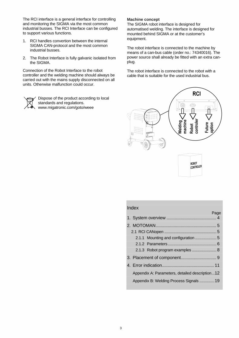
Machine concept The SIGMA robot interface is designed for automatised welding. The interface is designed for mounted behind SIGMA or at the customer’s equipment. The robot interface is connected to the machine by means of a can-bus cable (order no.: 74340016). The power source shall already be fitted with an extra can-plug. The robot interface is connected to the robot with a cable that is suitable for the used industrial bus.
Index Page 1. System overview .......................................... 4
2. MOTOMAN ................................................... 5 2.1 RCI CANopen ................................................. 5
2.1.1 Mounting and configuration .................... 5
2.1.2 Parameters .............................................. 6
2.1.3 Robot program examples ....................... 8
3. Placement of component.............................. 9
4. Error indication ............................................ 11
Appendix A: Parameters, detailed description ... 12
Appendix B: Welding Process Signals .............. 19
4
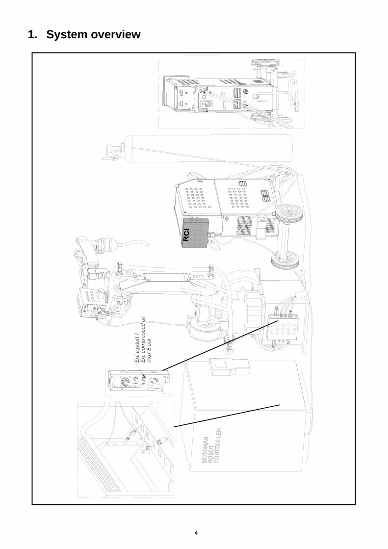
1. System overview
5
2. MOTOMAN 2.1 RCI CANopen
2.1.1 Mounting and configuration
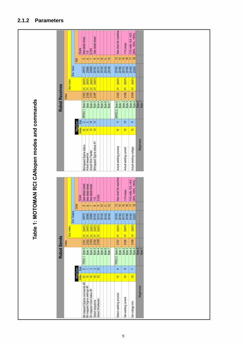
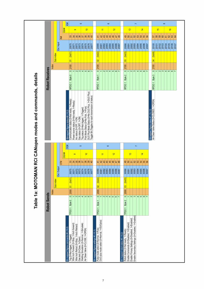
RCI CANopen can be used with a MOTOMAN NX100 robot controller, mounted with XFB01/CANopen slave interface board. RCI must be configured with a configuration file for MOTOMAN robot with article number xxxxxxxx. XFB01/CANopen must be set to the following: Baudrate : 250 Node address : 3 Please read MOTOMAN manual describing: Motoman NX100 Controller Fieldbus (XFB01) Instruction Manual Optional Anybus Interface Board Partnumber 147380-2 before mounting and configuring the XFB01/CANopen. RCI is connected to the XFB01/CANopen with a cable (article no.: 74340021) Hereafter, there will be access to control of the welding machine settings and commands as described in table 1. Detailed description of commands and settings can be seen in Appendix A
6
2.1.2 Parameters
7
8
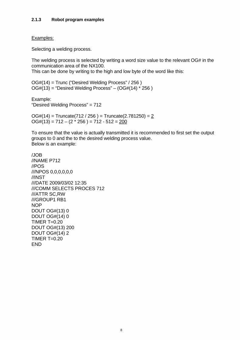
2.1.3 Robot program examples
Examples: Selecting a welding process. The welding process is selected by writing a word size value to the relevant OG# in the communication area of the NX100. This can be done by writing to the high and low byte of the word like this: OG#(14) = Trunc (“Desired Welding Process” / 256 ) OG#(13) = “Desired Welding Process” – (OG#(14) * 256 ) Example: “Desired Welding Process” = 712 OG#(14) = Truncate(712 / 256 ) = Truncate(2.781250) = 2 OG#(13) = 712 – (2 * 256 ) = 712 - 512 = 200 To ensure that the value is actually transmitted it is recommended to first set the output groups to 0 and the to the desired welding process value. Below is an example: /JOB //NAME P712 //POS ///NPOS 0,0,0,0,0,0 //INST ///DATE 2009/03/02 12:35 ///COMM SELECTS PROCES 712 ///ATTR SC,RW ///GROUP1 RB1 NOP DOUT OG#(13) 0 DOUT OG#(14) 0 TIMER T=0.20 DOUT OG#(13) 200 DOUT OG#(14) 2 TIMER T=0.20 END

9
3. Placement of component

11
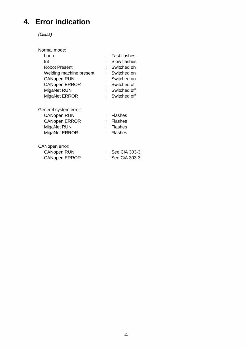
4. Error indication
(LEDs) Normal mode: Loop : Fast flashes Int : Slow flashes Robot Present : Switched on Welding machine present : Switched on CANopen RUN : Switched on CANopen ERROR : Switched off MigaNet RUN : Switched off MigaNet ERROR : Switched off
Generel system error: CANopen RUN : Flashes CANopen ERROR : Flashes MigaNet RUN : Flashes MigaNet ERROR : Flashes
CANopen error: CANopen RUN : See CiA 303-3 CANopen ERROR : See CiA 303-3

12
Appendix A:
Parameters, detailed description Behavior related parameters:
Name: Enable Commands
Description: This parameter must be set to “ON” before the welding machine accepts robot control of the commands: “Trig” “Wire Inch Forward” “Wire Inch Reverse” “Gas Test”
Restrictions: Unit: Binary Range: “OFF”, “ON” Name: Enable Primary Settings
Description: This parameter must be set to “ON” before the welding machine accepts robot control of the settings: “Select Welding Process” “Select Sequence”
Restrictions: Unit: Binary Range: “OFF”, “ON”
Name: Robot Status
Description: This parameter must be set to “ON” before the robot starts sending commands or settings to the welding machine.
Restrictions: Unit: Binary Range: “OFF”, “ON”
13
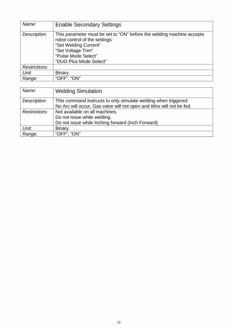
Name: Enable Secondary Settings
Description: This parameter must be set to “ON” before the welding machine accepts robot control of the settings: “Set Welding Current” “Set Voltage Trim” “Pulse Mode Select” “DUO Plus Mode Select”
Restrictions: Unit: Binary Range: “OFF”, “ON” Name: Welding Simulation
Description: This command instructs to only simulate welding when triggered. No Arc will occur, Gas valve will not open and Wire will not be fed.
Restrictions: Not available on all machines. Do not issue while welding. Do not issue while Inching forward (Inch Forward)
Unit: Binary Range: “OFF”, “ON”
14
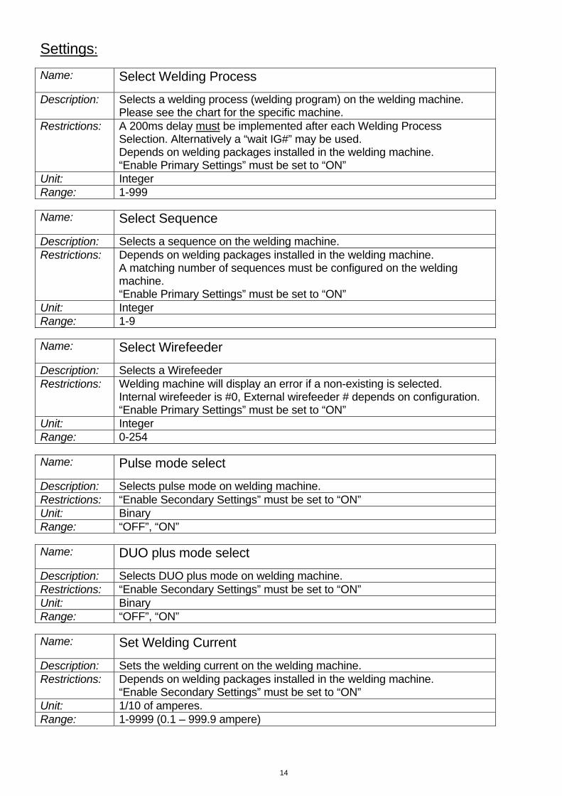
Settings: Name: Select Welding Process
Description: Selects a welding process (welding program) on the welding machine. Please see the chart for the specific machine.
Restrictions: A 200ms delay must be implemented after each Welding Process Selection. Alternatively a “wait IG#” may be used. Depends on welding packages installed in the welding machine. “Enable Primary Settings” must be set to “ON”
Unit: Integer Range: 1-999 Name: Select Sequence
Description: Selects a sequence on the welding machine. Restrictions: Depends on welding packages installed in the welding machine.
A matching number of sequences must be configured on the welding machine. “Enable Primary Settings” must be set to “ON”
Unit: Integer Range: 1-9 Name: Select Wirefeeder
Description: Selects a Wirefeeder Restrictions: Welding machine will display an error if a non-existing is selected.
Internal wirefeeder is #0, External wirefeeder # depends on configuration. “Enable Primary Settings” must be set to “ON”
Unit: Integer Range: 0-254 Name: Pulse mode select
Description: Selects pulse mode on welding machine. Restrictions: “Enable Secondary Settings” must be set to “ON” Unit: Binary Range: “OFF”, “ON” Name: DUO plus mode select
Description: Selects DUO plus mode on welding machine. Restrictions: “Enable Secondary Settings” must be set to “ON” Unit: Binary Range: “OFF”, “ON” Name: Set Welding Current
Description: Sets the welding current on the welding machine. Restrictions: Depends on welding packages installed in the welding machine.
“Enable Secondary Settings” must be set to “ON” Unit: 1/10 of amperes. Range: 1-9999 (0.1 – 999.9 ampere)

15
Name: Set Voltage Trim
Description: Sets the trim voltage on the welding machine. Restrictions: Depends on welding packages installed in the welding machine.
“Enable Secondary Settings” must be set to “ON” Unit: 1/10 of volts. Range: 50%..150% (equals -9.9..+9.9 volt)
16
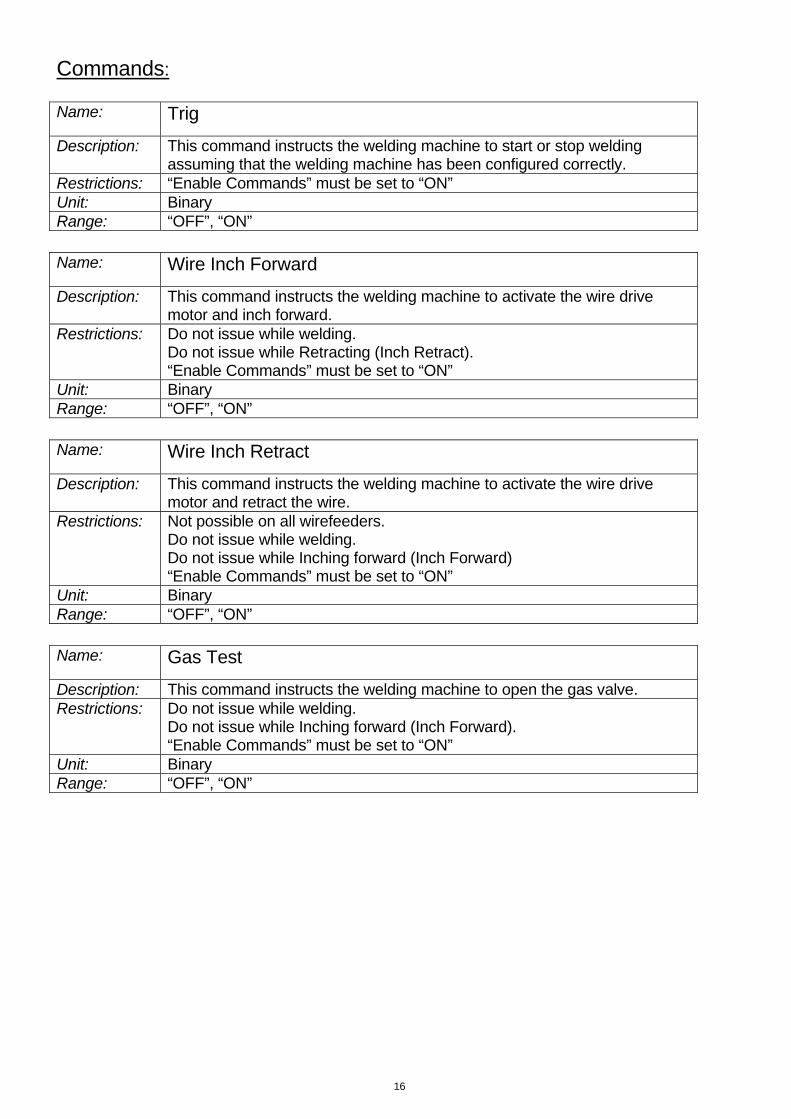
Commands: Name: Trig
Description: This command instructs the welding machine to start or stop welding assuming that the welding machine has been configured correctly.
Restrictions: “Enable Commands” must be set to “ON” Unit: Binary Range: “OFF”, “ON” Name: Wire Inch Forward
Description: This command instructs the welding machine to activate the wire drive motor and inch forward.
Restrictions: Do not issue while welding. Do not issue while Retracting (Inch Retract). “Enable Commands” must be set to “ON”
Unit: Binary Range: “OFF”, “ON” Name: Wire Inch Retract
Description: This command instructs the welding machine to activate the wire drive motor and retract the wire.
Restrictions: Not possible on all wirefeeders. Do not issue while welding. Do not issue while Inching forward (Inch Forward) “Enable Commands” must be set to “ON”
Unit: Binary Range: “OFF”, “ON” Name: Gas Test
Description: This command instructs the welding machine to open the gas valve. Restrictions: Do not issue while welding.
Do not issue while Inching forward (Inch Forward). “Enable Commands” must be set to “ON”
Unit: Binary Range: “OFF”, “ON”
17
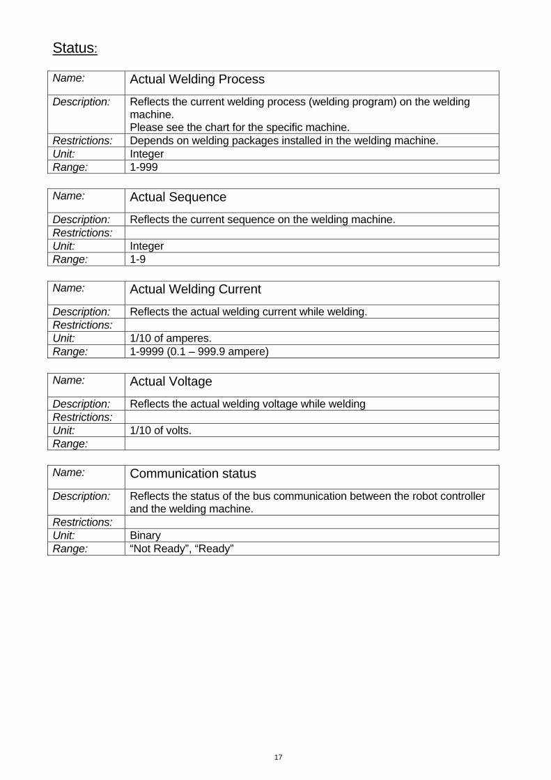
Status: Name: Actual Welding Process
Description: Reflects the current welding process (welding program) on the welding machine. Please see the chart for the specific machine.
Restrictions: Depends on welding packages installed in the welding machine. Unit: Integer Range: 1-999 Name: Actual Sequence
Description: Reflects the current sequence on the welding machine. Restrictions: Unit: Integer Range: 1-9 Name: Actual Welding Current
Description: Reflects the actual welding current while welding. Restrictions: Unit: 1/10 of amperes. Range: 1-9999 (0.1 – 999.9 ampere) Name: Actual Voltage
Description: Reflects the actual welding voltage while welding Restrictions: Unit: 1/10 of volts. Range: Name: Communication status
Description: Reflects the status of the bus communication between the robot controller and the welding machine.
Restrictions: Unit: Binary Range: “Not Ready”, “Ready”
18
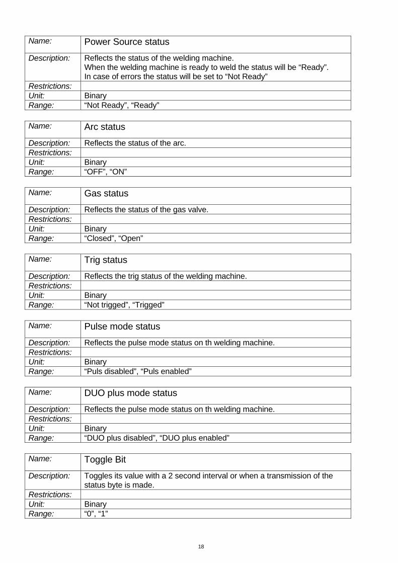
Name: Power Source status
Description: Reflects the status of the welding machine. When the welding machine is ready to weld the status will be “Ready”. In case of errors the status will be set to “Not Ready”
Restrictions: Unit: Binary Range: “Not Ready”, “Ready” Name: Arc status
Description: Reflects the status of the arc. Restrictions: Unit: Binary Range: “OFF”, “ON” Name: Gas status
Description: Reflects the status of the gas valve. Restrictions: Unit: Binary Range: “Closed”, “Open” Name: Trig status
Description: Reflects the trig status of the welding machine. Restrictions: Unit: Binary Range: “Not trigged”, “Trigged” Name: Pulse mode status
Description: Reflects the pulse mode status on th welding machine. Restrictions: Unit: Binary Range: “Puls disabled”, “Puls enabled” Name: DUO plus mode status
Description: Reflects the pulse mode status on th welding machine. Restrictions: Unit: Binary Range: “DUO plus disabled”, “DUO plus enabled” Name: Toggle Bit
Description: Toggles its value with a 2 second interval or when a transmission of the status byte is made.
Restrictions: Unit: Binary Range: “0”, “1”
19
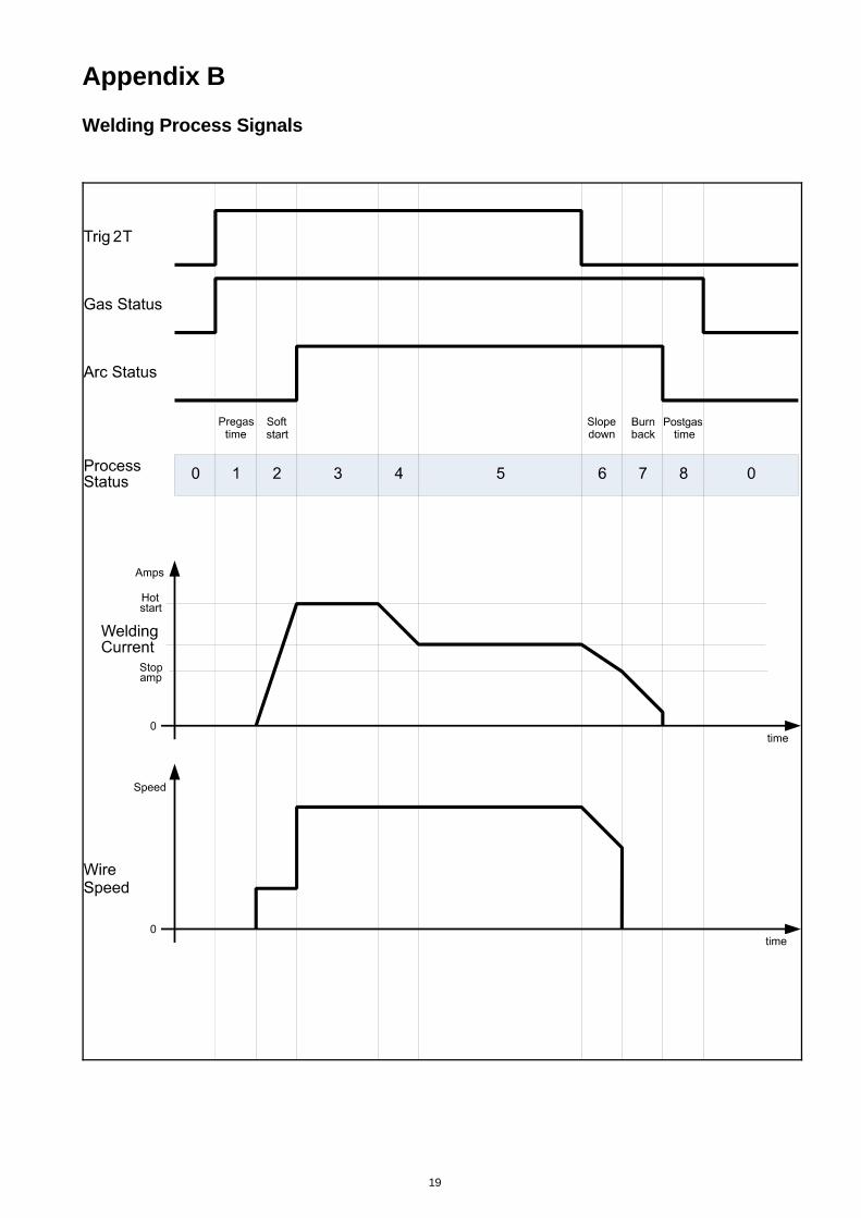
Appendix B
Welding Process Signals
20
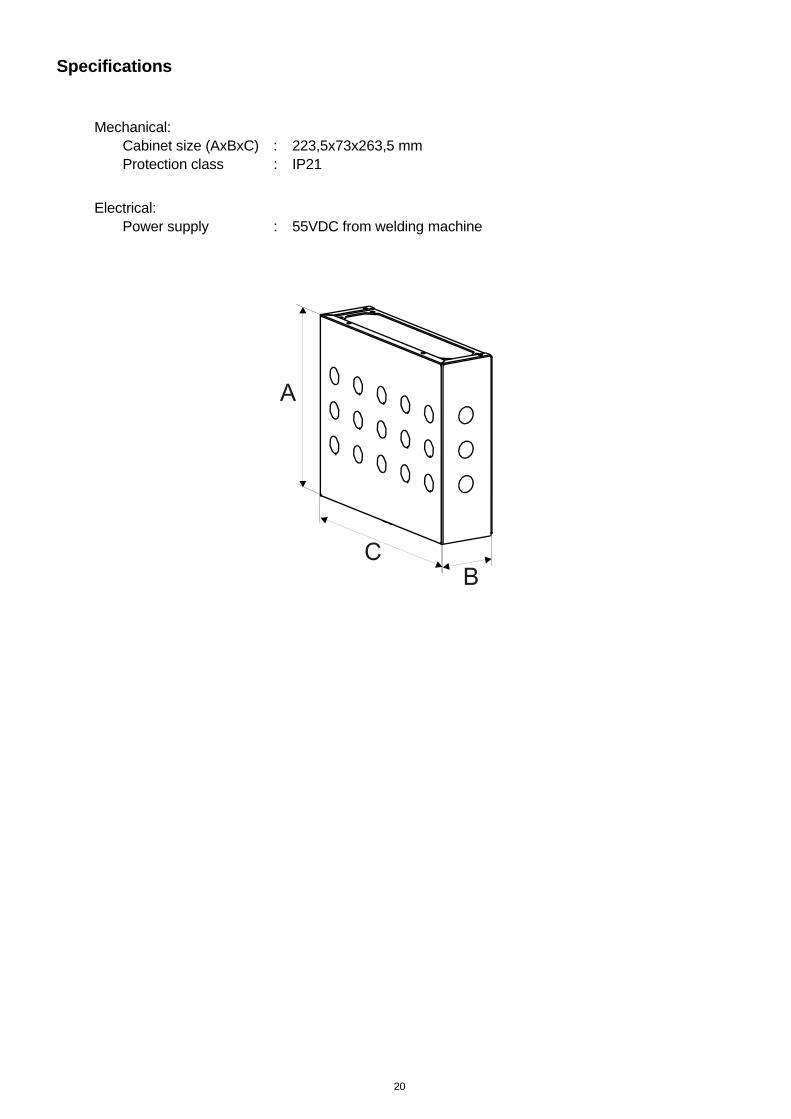
Specifications
Mechanical: Cabinet size (AxBxC) : 223,5x73x263,5 mm Protection class : IP21
Electrical: Power supply : 55VDC from welding machine

21
Reservedelsliste
Spare parts list
Ersatzteilliste
Liste des pièces de rechange
22
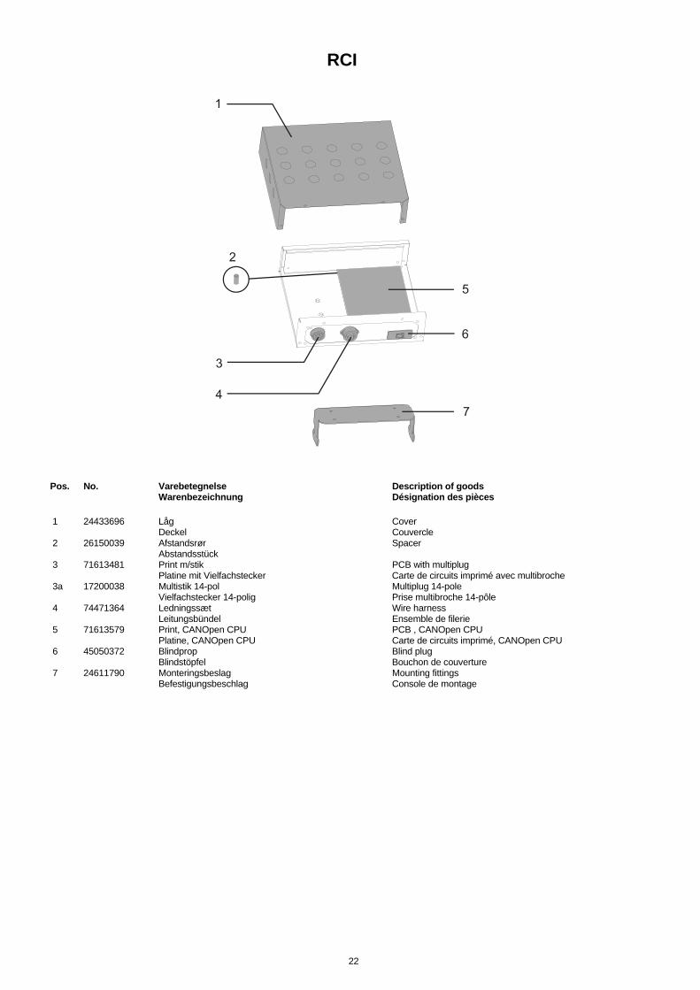
RCI
Pos. No. Varebetegnelse Description of goods Warenbezeichnung Désignation des pièces 1 24433696 Låg Cover Deckel Couvercle 2 26150039 Afstandsrør Spacer Abstandsstück 3 71613481 Print m/stik PCB with multiplug Platine mit Vielfachstecker Carte de circuits imprimé avec multibroche 3a 17200038 Multistik 14-pol Multiplug 14-pole Vielfachstecker 14-polig Prise multibroche 14-pôle 4 74471364 Ledningssæt Wire harness Leitungsbündel Ensemble de filerie 5 71613579 Print, CANOpen CPU PCB , CANOpen CPU Platine, CANOpen CPU Carte de circuits imprimé, CANOpen CPU 6 45050372 Blindprop Blind plug Blindstöpfel Bouchon de couverture 7 24611790 Monteringsbeslag Mounting fittings Befestigungsbeschlag Console de montage

23
.
Bundesrepublik Deutschland: MIGATRONIC SCHWEISSMASCHINEN GmbH Sandusweg 12, D-35435 Wettenberg Telefon: (+49) 641 982840 Telefax: (+49) 641 9828450 Czech Republic: MIGATRONIC CZECH REPUBLIC a.s. Tolstého 451, 415 03 Teplice, Czech Republic Telefon: (+42) 0411 135 600 Telefax: (+42) 0417 533 072 Danmark: MIGATRONIC AUTOMATION A/S Knøsgårdvej 112, 9440 Aabybro Telefon: (+45) 96 96 27 00 Telefax: (+45) 96 96 27 01 Danmark: SVEJSEMASKINEFABRIKKEN MIGATRONIC Aggersundvej 33, 9690 Fjerritslev Telefon: (+45) 96 500 600 Telefax: (+45) 96 500 601 Finland: MIGATRONIC OY PL105, 04301 Tuusula, Finland Tel. (+358) 0102 176500
France: MIGATRONIC EQUIPEMENT DE SOUDURE S.A.R.L. Parc Avenir II, 313 Rue Marcel Merieux, F-69530 Brignais Tél: (+33) 478 50 6511 Télécopie: (+33) 478 50 1164 Hungary: MIGATRONIC KFT Szent Miklos u. 17/a, H-6000 Kecskemét Tel./fax:+36/76/505-969;481-412;493-243 India: Migatronic India Private Ltd. 22, Sowri Street, Alandur, 600 016 Chennai, India Tel.: (0091 44) 22300074 Telefax: (0091 44) 22300064 Italia: MIGATRONIC s.r.l. Via dei Quadri 40, 20871 Vimercate (MB) Italy Tel.: (+39) 039 92 78 093 Telefax: (+39) 039 92 78 094 Nederland: MIGATRONIC NEDERLAND B.V. Hallenweg 34, NL-5683 CT Best Tel.:(+31) 499 37 50 00 Telefax: (+31) 499 37 57 95
Norge: MIGATRONIC NORGE A/S Industriveien 1, N-3300 Hokksund Tel. (+47) 32 25 69 00 Telefax: (+47) 32 25 69 01 Sverige: MIGATRONIC SVETSMASKINER AB Nääs Fabriker, Box 5015, S-448 50 TOLLERED Tel. (+46) 31 44 00 45 Telefax: (+46) 31 44 00 48 United Kingdom: MIGATRONIC WELDING EQUIPMENT LTD. 21, Jubilee Drive, Belton Park, Loughborough GB-Leicestershire LE11 5XS Tel. (+44) 15 09 26 74 99 Fax: (+44) 15 09 23 19 59 Homepage: www.migatronic.com