rc48c - mining publicationsminingpublications.com/images/hitlist/rc48c.pdf · bender industrial...
TRANSCRIPT
Bender Industrial Products - 700 Fox Chase - Coatesville PA 19320 - Tel. (800)-356-4266 - Fax. (610) 383-7100 - www.bender.org
RC48C
Ground-Fault Ground-Continuity Monitorfor AC systems in Mining applications
FunctionThe RC48C ground-fault ground-continuity monitor:
- Measures the residual current in the respective circuit or branch of the system by means of a BENDER residual current transformer. For that purpose, all active conductors (phases + neutral) are to be passed through the residual current transformer.If the residual current exceeds the response value the “Alarm Ground Fault” LED lights and the alarm relay switches. The alarm contact can be delayed by a selectable time. The alarm remains stored until the RESET button is pressed.
- Monitors the the impedance of the grounding conductor. For that purpose, the RC48C superimposes a voltage of 12 V between the terminals G (G = grounding conductor) and GC (GC = ground check). Connect the respective conductors of the cable to these terminals. Connect a termination device E6... between both conductors at the other end of the cable to be monitored. By evaluating the voltage drop at this termination device, the RC48C recognizes series resistance faults (cable high-resistance or open) or cross resistance faults (short circuit) of the cable.
The alarm relay trips immediately if a series resistance or a cross resistance fault occurs. As soon as the cause of the alarm no longer exists, the relay automatically deenergizes again.
Alarm messages are also indicated by the LED “Alarm Ground Fault” on the RC48C or on a remote alarm indicator and operator panel. The alarm message “Ground Check Fault” is indicated at the RC48C only.
The alarm relay can be used for the tripping of a contactor or load switch. Depending on the type of load switch the operating mode of the alarm relay can be set to N/O (shunt) operation or N/C (UV) operation.
The termination device E6S-T is distinguished from the other termination devices in that it has an additional resistor for remote switch-off. If this resistor is activated by an external NC contact, an alarm (Ground Check Fault) occurs. The connected load switch disconnects the system via the alarm relay.
RC48C
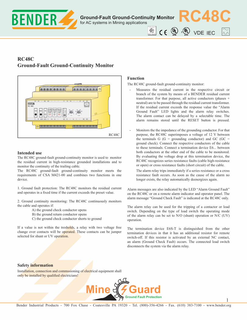
RC48CGround-Fault Ground-Continuity Monitor
Intended useThe RC48C ground-fault ground-continuity monitor is used to monitor the residual current in high-resistance grounded installations and to monitor the continuity of the trailing cable. The RC48C ground-fault ground-continuity monitor meets the requirements of CSA M421-00 and combines two functions in one device.
1. Ground fault protection: The RC48C monitors the residual current and operates in a fixed time if the current exceeds the preset value.
2. Ground continuity monitoring: The RC48C continuously monitors the cable and operates if: A) the ground check conductor opens B) the ground return conductor opens C) the ground check conductor shorts to ground
If a value is not within the tresholds, a relay with two voltage free change over contacts will be operated. These contacts can be jumper selected for shunt or UV operation.
Safety information Installation, connection and commssioning of electrical equipment shall only be installed by qualified electricians!
1
Quality SystemCertif ied
I S O 9 0 0 1 VDE IEC
Bender Industrial Products - 700 Fox Chase - Coatesville PA 19320 - Tel. (800)-356-4266 - Fax. (610) 383-7100 - www.bender.org
RC48C
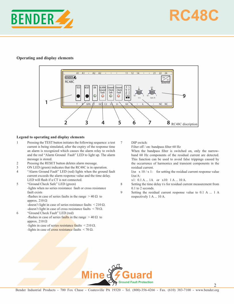
Operating and display elements
Legend to operating and display elements 1 Pressing the TEST button initiates the following sequence: a test
current is being simulated, after the expiry of the response time an alarm is recognized which causes the alarm relay to switch and the red “Alarm Ground Fault” LED to light up. The alarm message is stored.
2 Pressing the RESET button deletes alarm message.3 ON LED (green) indicates that the RC48C is in operation.4 “Alarm Ground Fault” LED (red) lights when the ground fault
current exceeds the alarm response value and the time delay. LED will flash if a CT is not connected.5 “Ground Check Safe” LED (green) -lights when no series resistance fault or cross resistance fault exists -flashes in case of series faults in the range > 40 Ω to approx. 210 Ω -doesn’t light in case of series resistance faults < 210 Ω. -doesn’t light in case of cross resistance faults < 70 Ω.6 “Ground Check Fault” LED (red) -flashes in case of series faults in the range > 40 Ω to approx. 210 Ω -lights in case of series resistance faults < 210 Ω. -lights in case of cross resistance faults < 70 Ω.
7 DIP switch: Filter off / on: bandpass filter 60 Hz When the bandpass filter is switched on, only the narrow-
band 60 Hz components of the residual current are detected. This function can be used to avoid false trippings caused by the occurrence of harmonics and transient components in the residual current.
I∆n x 10 / x 1: for setting the residual current response value I∆n/A:
x1: 0.1 A ... 1A or x10: 1 A ... 10 A.8 Setting the time delay t/s for residual current measurement from
0.1 to 2 seconds.9 Setting the residual current response value to 0.1 A ... 1 A
respectively 1 A ... 10 A.
RC48C discription
2
Bender Industrial Products - 700 Fox Chase - Coatesville PA 19320 - Tel. (800)-356-4266 - Fax. (610) 383-7100 - www.bender.org
RC48C
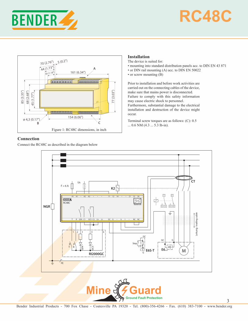
InstallationThe device is suited for:• mounting into standard distribution panels acc. to DIN EN 43 871• or DIN rail mounting (A) acc. to DIN EN 50022• or screw mounting (B)
Prior to installation and before work activities are carried out on the connecting cables of the device, make sure that mains power is disconnected.Failure to comply with this safety information may cause electric shock to personnel.Furthermore, substantial damage to the electrical installation and destruction of the device might occur.
Terminal screw torques are as follows: (C): 0.5 ... 0.6 NM (4.3 ... 5.3 lb-in).
Figure 1: RC48C dimensions, in inch
ConnectionConnect the RC48C as described in the diagram below
3
Bender Industrial Products - 700 Fox Chase - Coatesville PA 19320 - Tel. (800)-356-4266 - Fax. (610) 383-7100 - www.bender.org
RC48C
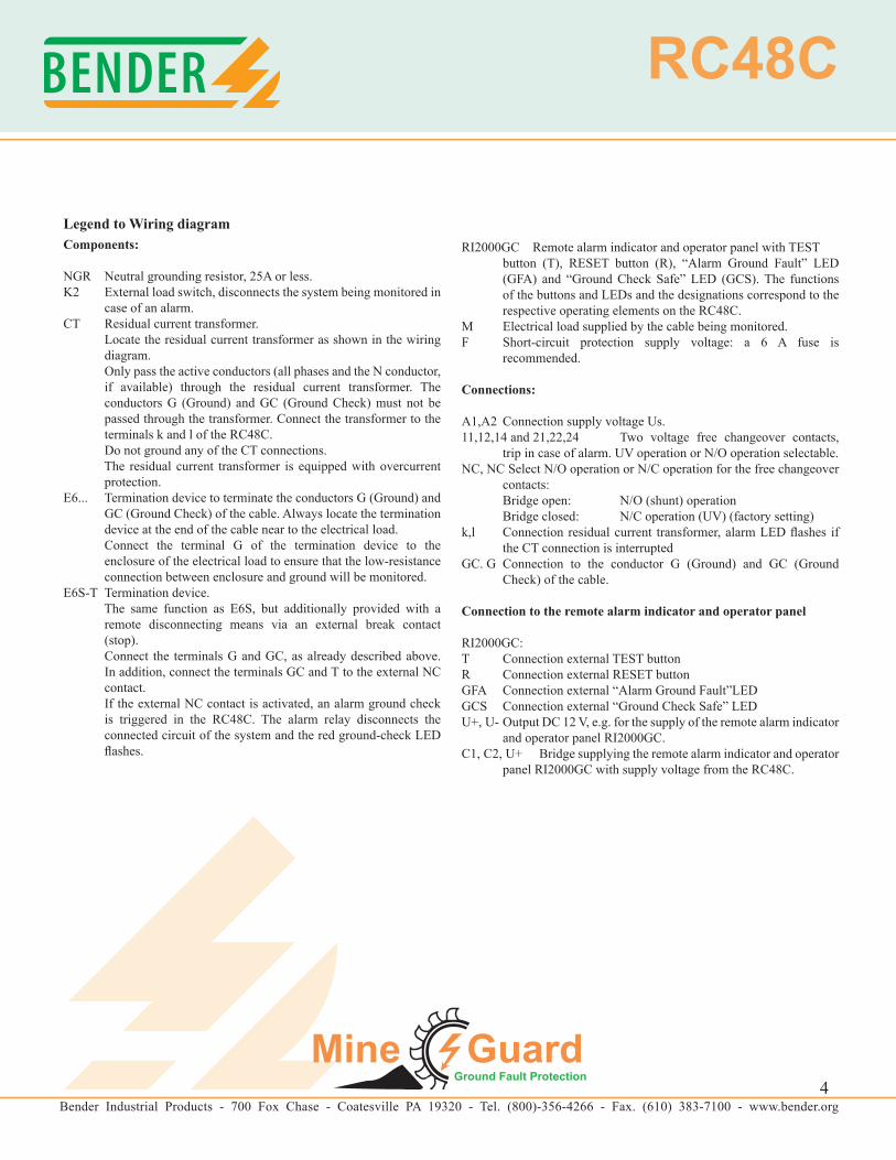
Legend to Wiring diagramComponents:
NGR Neutral grounding resistor, 25A or less.K2 External load switch, disconnects the system being monitored in
case of an alarm.CT Residual current transformer. Locate the residual current transformer as shown in the wiring
diagram. Only pass the active conductors (all phases and the N conductor,
if available) through the residual current transformer. The conductors G (Ground) and GC (Ground Check) must not be passed through the transformer. Connect the transformer to the terminals k and l of the RC48C.
Do not ground any of the CT connections. The residual current transformer is equipped with overcurrent
protection.E6... Termination device to terminate the conductors G (Ground) and
GC (Ground Check) of the cable. Always locate the termination device at the end of the cable near to the electrical load.
Connect the terminal G of the termination device to the enclosure of the electrical load to ensure that the low-resistance connection between enclosure and ground will be monitored.
E6S-T Termination device. The same function as E6S, but additionally provided with a
remote disconnecting means via an external break contact (stop).
Connect the terminals G and GC, as already described above. In addition, connect the terminals GC and T to the external NC contact.
If the external NC contact is activated, an alarm ground check is triggered in the RC48C. The alarm relay disconnects the connected circuit of the system and the red ground-check LED flashes.
RI2000GC Remote alarm indicator and operator panel with TEST button (T), RESET button (R), “Alarm Ground Fault” LED (GFA) and “Ground Check Safe” LED (GCS). The functions of the buttons and LEDs and the designations correspond to the respective operating elements on the RC48C.
M Electrical load supplied by the cable being monitored.F Short-circuit protection supply voltage: a 6 A fuse is
recommended.
Connections:
A1,A2 Connection supply voltage Us.11,12,14 and 21,22,24 Two voltage free changeover contacts,
trip in case of alarm. UV operation or N/O operation selectable.NC, NC Select N/O operation or N/C operation for the free changeover
contacts: Bridge open: N/O (shunt) operation Bridge closed: N/C operation (UV) (factory setting)k,l Connection residual current transformer, alarm LED flashes if
the CT connection is interrupted GC. G Connection to the conductor G (Ground) and GC (Ground
Check) of the cable.
Connection to the remote alarm indicator and operator panel
RI2000GC:T Connection external TEST buttonR Connection external RESET buttonGFA Connection external “Alarm Ground Fault”LEDGCS Connection external “Ground Check Safe” LEDU+, U- Output DC 12 V, e.g. for the supply of the remote alarm indicator
and operator panel RI2000GC.C1, C2, U+ Bridge supplying the remote alarm indicator and operator
panel RI2000GC with supply voltage from the RC48C.
4

Bender Industrial Products - 700 Fox Chase - Coatesville PA 19320 - Tel. (800)-356-4266 - Fax. (610) 383-7100 - www.bender.org
RC48C
Technical dataInsulation coordination acc. to IEC 60664-1:Rated insulation voltage AC 250 VRated impulse withstand voltage/contamination level 2.5 kV/3
Voltage Ranges:Supply voltage US AC/DC 60 ... 264 V, 50 / 60 HzFuse recommended: 6 A slow fusePower consumption approx. 5 VA at AC 60 V approx. 8.5 VA at AC 264 V
Residual-Current Monitoring:Response value, residual current adjustable 0.1 ... 1 A resp. 1 ... 10 A Accuracy + 0 ... - 25 %Response delay adjustable 0.1 ... 2 sAccuracy of the response delay ± 20 %Continuous short circuit current 200 A 2500 A for 2 secondsOperating mode latching
Ground-Conductor Monitoring:Response value, series resistance fault 40 ΩAccuracy +/-10 ΩNo-load voltage DC12VΟutput impedance 240 ΩRated current of the measuring loop AC25V continuousProtection against stray voltage AC120V for 3 secondsDelay on release 1.5 sResponse time, series resistance faults 0.2 sResponse time, cross resistance faults 0,2 sAccuracy of the response time ± 20 %Operating mode non latching
Inputs:Connection to the residual current transformer: Single wire, 0.75 mm2 (AWG 18) up to 1 m (3’)Single wire, twisted 0,.5 mm2 (AWG 18) 1 ... 10 m (3 ... 30’)Shielded cable 0.75 mm2 (AWG 18) (shield to Ground) 10 ... 25 m (30 ... 75’)
Outputs:Switching elements (alarm relay) 2 Form C contactsRated contact voltage AC 250 V / DC 300 VLimited making capacity AC/DC 5 ALimited breaking capacity AC/DC 2/0.2 APermissible number of operating cycles 12000 cyclesOperating mode (alarm relay), selectable N/O (shunt) operation
or N/C (UV) operationSwitching elements (GFA, GCS) 1 NO contact eachRated contact voltage AC 250 V / DC 300 VLimited making capacity AC/DC 5 ALimited breaking capacity AC/DC 2/0.2 APermissible number of operating cycles 12000 cycles
Type Tests: Test of the electromagnetic compatibility (EMC) Immunity according to IEC 62020 Emission according to EN 50081 Emissions according to EN 55011/CISPR11 class A
General data:Ambient temperature, during operation - 40 °C ...+ 60 °C
(233 K ... 333 K)Storage temperature range - 55 °C ... + 80 °C
(218 ... 353 K)Climatic class acc. to IEC 60721 3K5Operating mode continuous operationMounting any positionConnection screw terminalsCross sectional area of connecting cable, single wire 0,2 ... 4 mm2 (AWG 24 to 12)Cross sectional area of connecting cable, flexible 0,2 ... 2,5 mm2 (AWG 24 to 14)Protection class according to DIN EN 60529 Built-in components IP 30Terminals/with terminal covers IP 20Flammability class UL94V-0Weight approx. 360 g
Applied StandardsCSA M421-00: July 2000: Use of electricity in minesAS 2081.1 - AS2081.5: Electrical equipment for Coal and Shale MinesIEC 62020:1998-08 Residual Current Monitors
5
Bender Industrial Products - 700 Fox Chase - Coatesville PA 19320 - Tel. (800)-356-4266 - Fax. (610) 383-7100 - www.bender.org
RC48C
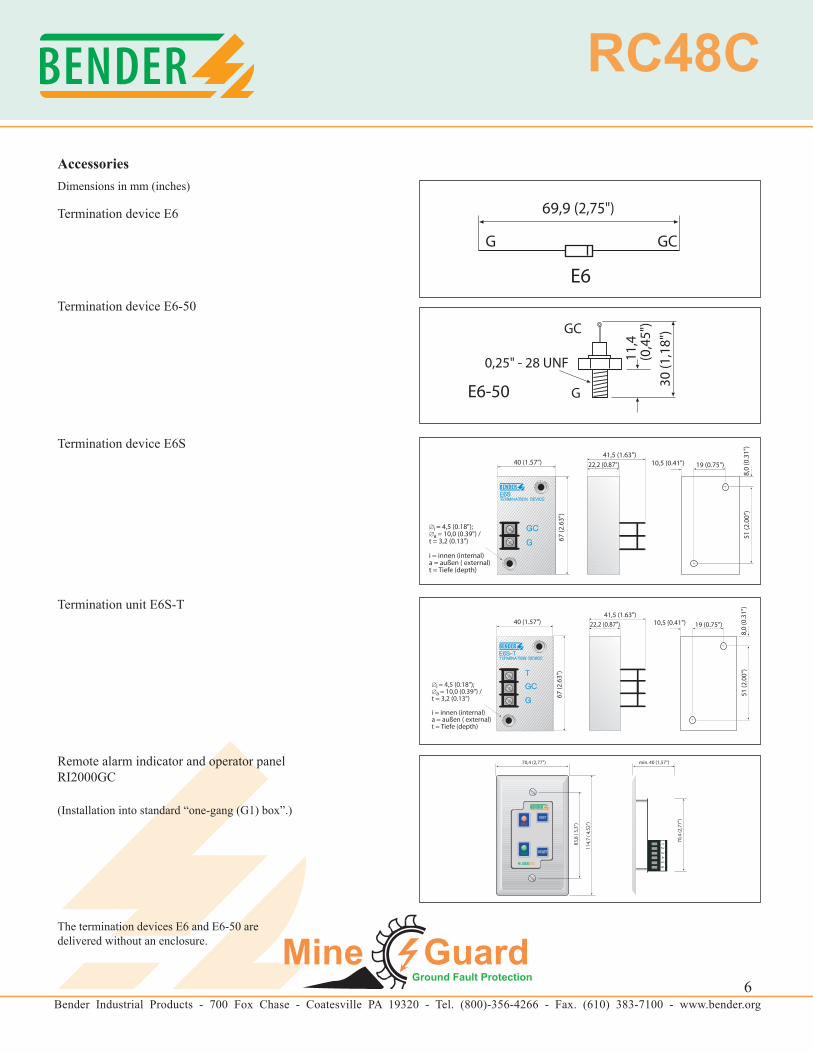
AccessoriesDimensions in mm (inches)
Termination device E6
Termination device E6-50
Termination device E6S
Termination unit E6S-T
Remote alarm indicator and operator panelRI2000GC
(Installation into standard “one-gang (G1) box”.)
The termination devices E6 and E6-50 are delivered without an enclosure.
6
Bender Industrial Products - 700 Fox Chase - Coatesville PA 19320 - Tel. (800)-356-4266 - Fax. (610) 383-7100 - www.bender.org
RC48C
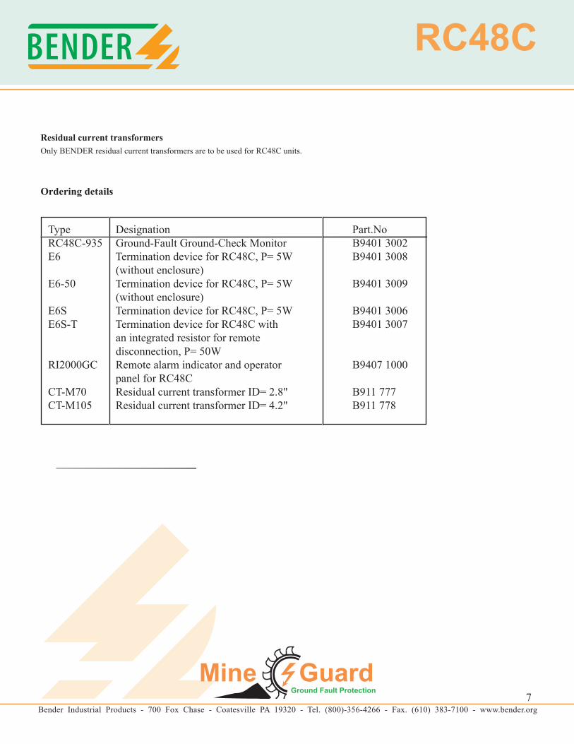
Residual current transformersOnly BENDER residual current transformers are to be used for RC48C units.
Ordering details
Type Designation Part.NoRC48C-935 Ground-Fault Ground-Check Monitor B9401 3002E6 Termination device for RC48C, P= 5W B9401 3008 (without enclosure)E6-50 Termination device for RC48C, P= 5W B9401 3009 (without enclosure)E6S Termination device for RC48C, P= 5W B9401 3006E6S-T Termination device for RC48C with B9401 3007 an integrated resistor for remote disconnection, P= 50WRI2000GC Remote alarm indicator and operator B9407 1000 panel for RC48C CT-M70 Residual current transformer ID= 2.8" B911 777CT-M105 Residual current transformer ID= 4.2" B911 778
7