rapport sgc 201 · rapport sgc 201 •1102-7371 • isrn ... in collaboration between cat and swep...
TRANSCRIPT
Rapport SGC 201
Catalytic burners in larger boiler appliances
©Svenskt Gastekniskt Center – Februari 2009
Fredrik Silversand & Mikael PerssonFredrik Silversand & Mikael PerssonCatator AB
Rapport SGC 201 •1102-7371 • ISRN SGC-R-201-SE
SGC:s FÖRORD FUD-projekt inom Svenskt Gastekniskt Center AB avrapporteras normalt i rapporter som är fritt tillgängliga för envar intresserad. SGC svarar för utgivningen av rapporterna medan uppdragstagarna för respektive projekt eller rapportförfattarna svarar för rapporternas innehåll. Den som utnyttjar eventuella beskrivningar, resultat e dyl i rapporterna gör detta helt på eget ansvar. Delar av rapport får återges med angivande av källan. En förteckning över hittills utgivna SGC-rapporter finns på SGC´s hemsida www.sgc.se. Svenskt Gastekniskt Center AB (SGC) är ett samarbetsorgan för företag verksamma inom energigasområdet. Dess främsta uppgift är att samordna och effektivisera intressenternas insatser inom områdena forskning, utveckling och demonstration (FUD). SGC har följande delägare: Svenska Gasföreningen, E.ON Gas Sverige AB, E.ON Sverige AB, Lunds Energikoncernen AB (publ), Göteborg Energi AB, och Öresundskraft AB. Följande parter har gjort det möjligt att genomföra detta utvecklingsprojekt: Statens Energimyndighet Catator AB ICI Caldaie S.p.A SVENSKT GASTEKNISKT CENTER AB Jörgen Held
34
Summary Catator AB (CAT) has been working in the field of catalytic combustion technology for more than one decade. Specially designed catalysts and burner systems have been developed for a variety of applications. Indeed, catalytic combustion offers a high degree of flexibility with respect to fuel composition and operation conditions. Moreover, the emissions of nitrogen oxides are generally far below the values found in conventional combustion. The possibility to combine CATs wire-mesh catalyst [1] with an innovative boiler design has previously been demonstrated in collaboration between CAT and SWEP International AB (SWEP) [2]. Catalytic combustion enables a super compact packaging approach together with excellent combustion performance, low emissions and peak efficiency. The capacity approaches 10 MW/m3 of gross volume and the emission of nitrogen oxides is generally less than 30 mg/kWh at 105-107% efficiency (LHV). The CAT-SWEP heat engine is currently under pre-evaluation for large-scale commercialization. The implementation of the Ecodesign directive is expected to speed up the commercialization of clean combustion technology [3]. This project focuses on the scale up of a CATs catalytic burner technology to enable retrofit installation in existing boilers and the design of new innovative combinations of catalytic burners and boilers. Different design approaches are discussed and evaluated in the report and suggestions are made concerning scale-up. Preliminary test data, extracted from a large boiler installation are discussed together with an accurate analysis of technical possibilities following an optimization of the boiler design to benefit from the advantages of catalytic combustion. The experimental work was conducted in close collaboration with ICI Caldaie (ICI), located in Verona, Italy. ICI is a leading European boiler manufacturer in the effect segment ranging from about 20 kWt to several MWt.ICI is also designing CHP-platforms based on the fuel cell technology. The study shows that it is possibly to scale up the burner technology and to maintain low emissions. The boilers used in the study were designed around conventional combustion and were consequently not optimized for implementation of catalytic burners. From previous experiences it stands clear that the furnace volume can be dramatically decreased when applying catalytic combustion [2]. In flame combustion, this volume is normally dimensioned to avoid flame impingement on cold surfaces and to facilitate completion of the gas-phase reactions. The emissions of nitrogen oxides can be reduced by decreasing the residence time in the furnace. Even with the over-dimensioned furnace used in this study, we easily reached emission values close to 35 mg/kWh. The emissions of carbon monoxide and unburned hydrocarbons were negligible (less than 5 ppmv). It is possible to decrease the emissions of nitrogen oxides further by designing the furnace/boiler around the catalytic burner, as suggested in the report. Simultaneously, the size of the boiler installation can be reduced greatly, which also will result in material savings, i.e. the production cost can be reduced. It is suggested to optimize the boiler design to benefit from all advantages provided by catalytic combustion. Such work will include design and construction of an innovative boiler system, in the effect segment of 100- 200 kWt. The boiler system will then be evaluated with CATs catalytic burner technology.

35
Sammanfattning Catator AB (CAT) har varit verksamma inom området katalytisk förbränning under mer än ett decennium. Ett antal förbränningskatalysatorer och brännaresystem har utvecklats för ett stort antal applikationer. Katalytisk förbränning erbjuder en stor förbränningsmässig flexibilitet och kan, om systemen utformas på lämpligt sätt, möjliggöra betydande miljövinster med avseende på bl.a. kväveoxider (NOx). Möjligheterna att kombinera CATs nätkatalysator [1] med innovativa panndesigner har demonstrerats i tidigare projekt, bl.a. genom samarbetet mellan CAT och SWEP International AB (SWEP) [2]. Katalytisk förbränning medger miljövänlig förbränning vid hög verkningsgrad i mycket kompakta panngeometrier. I innovativa panngeometrier är det möjligt att uppnå full avgaskondensation vid effekttätheter på 10 MW per kubikmeter och samtidigt begränsa emissionerna till ca. 30 mg NOx/kWh. CAT-SWEP-designen utvärderas f.n. av ett flertal ledande panntillverkare i Europa. EcoDesign-direktivet förväntas påskynda kommersialiseringen av miljövänlig förbränningsteknik [3]. Detta projekt fokuserar på en uppskalning av CATs katalytiska brännare för att möjliggöra efterinstallation i befintliga pannor. Dessutom undersöks möjligheterna att nyttja katalytisk förbränning i större innovativa panndesigner där pannans egenskaper anpassats efter de möjligheter som katalytisk förbränning ger. I rapporten redovisas experimentella resultat från undersökningar med olika designalternativ. Katalytiska brännare har installerats i pannor från ICI Caldaie (ICI) i Verona, Italien. ICI är en ledande tillverkare av pannor i effektsegmentet ca 20 kWt upp till flera MWt. ICI håller också på att utveckla system för kombinerad värme-och kraft baserade på bränslecellsteknik. Studien visar att det är möjligt att konstruera större katalytiska brännare som medger låga NOx-emissioner. De kommersiella pannor som har använts i denna studie är utvecklade för konventionell flamförbränning och har således inte optimerats för katalytisk förbränning. Det är sedan tidigare känt att pannvolymen kan reduceras väsentligt vid insats av katalytisk förbränning. Vid konventionell flamförbränning dimensioneras pannrummet generellt efter flammans storlek. Detta medför att förbränningsrummet blir voluminöst och att rökgasernas uppehållstid i förbränningsrummet förlängs. Detta förhållande medför sekundärt att NOx-bildningen ökar. Ett sätt att reducera NOx-bildningen är således att begränsa rökgasernas uppehållstid i den heta zonen, d.v.s. att nyttja en innovativ panndesign inkluderande katalytisk förbränning. Resultaten visar att det är fullt möjligt att nå låga NOx-värden (nära 35 mg/kWh) även i överdimensionerade konventionella pannor. Emissionerna av CO och oförbrända kolväten är samtidigt försumbara (fåtal ppmv). Det är möjligt att ytterligare minska emissionerna av kväveoxider genom att anpassa pannan efter den katalytiska brännarens förutsättningar, vilket diskuteras i rapporten. Samtidigt kan pannans storlek minskas avsevärt, vilket leder till lägre materialkostnader. En eventuell fortsättning av arbetet bör fokusera på förbättrad panndesign så att fördelarna med katalytisk förbränning kan utnyttjas maximalt. En lämplig storlek på pannan är 100-200 kWt.

List of content Section Page 1. Introduction 1 2. Aims and objective 2 3. Fundamentals of catalytic combustion 2
3.1 Nitrogen oxides 2 3.2 Modes of combustion 5 3.3 Flash back 9 3.4 Durability 10
4. Previous work 11 5. Pre-evaluations in a small boiler installation 14
5.1 Boiler design 14 5.2 Design options and results 17
6. Scale-up possibilities and issues 25 7. Innovative boiler designs 30 8. Conclusions and future work 32 9. Literature 33

1
1. Introduction Catator AB (CAT) has been working in the field of catalytic combustion for a number of years. A special wire-mesh catalyst has been developed for this application and the concept has been evaluated in a number of applications [4]. Catalytic combustion is very flexible with respect to fuel composition and operation conditions. Indeed, the same catalyst and burner configuration can be used for different gases, i.e. Hythane, natural gas, LPG, biogas and landfill gas. It is even possible to burn liquid fuels with minor modifications of the fuel inlet. Catalytic burners can be designed for ultralow emission of nitrogen oxides (NOx), carbon monoxide (CO) and hydrocarbons (HC). Depending on the surface load (kWt/dm2), it is possible to reach NOx-levels as low as 5 mg/kWh. The Ecodesign directive under implementation will demand NOx-emissions of less than 35 mg/kWh for the highest rating. Catalytic burners will easily comply with such demands. In catalytic combustion, the combustion mechanism is somewhat different as compared to ordinary flame combustion. The combustion reaction is initiated by a surface reaction involving a catalytic component, usually palladium. If the gas velocity is low enough, all combustion will occur on the catalyst surface. When the gas load is increased, we will reach an intermediate region where radicals are produced on the catalyst and are emitted into the gas. These free radicals will speed up the combustion process greatly and we normally talk about hybrid combustion and heterogeneously assisted homogeneous combustion [5]. If the gas load is increased further, the catalyst will merely act as a gas distributor for surface combustion. Very thin blue flames are formed over the surface and the NOx-emission will increase as compared to pure surface combustion or hybrid combustion. Even if it is possible to almost reach zero emissions with respect to NOx, catalytic burners are generally designed to work in the transition regime between hybrid combustion and blue-flame combustion. Such design approaches enable a compact burner/boiler design. CAT has previously reported on an innovative heat-exchanger burner, which has been developed in close collaboration with SWEP International [2]. This device was originally designed for wall-hanged boilers in the effect segment up to about 30 kWt. Following a number of design optimizations and long-term evaluations this design is now ready for commercialization. The Ecodesign criteria are expected to speed up the implementation phase. This study focuses on the scale-up of catalytic burners for installation in large boiler appliances. Retrofit installations are possible even if it is believed that such measures will suffer from inadequate utilization of the advantages of catalytic combustion. In order to take full advantage of catalytic combustion, the boiler should be re-designed to some extent. Careful evaluations indicate that such re-design generally will provide relatively more compact and light-weight boilers. In addition, it would be possible to reduce the production cost in total.
2
This study has been conducted in collaboration with ICI Caldaie (ICI) in Verona Italy. ICI is a leading boiler manufacturer with export to several European countries. They produce different types of boilers according to: - Steel boilers, 22 kWt – 3.5 MWt - High power hot water boilers, up to 20 MWt - Condensing boilers, 57 kWt – 2.3 MWt - Industrial steam boilers, 67 kWt – 14 MWt - Thermal oil heater, 116 kWt – 10 MWt In addition, ICI is developing a complete CHP-unit based on fuel cells (Sidera 30). ICI has provided boilers for this study and they have also contributed with their expertise with respect to burners, boilers and control/automation. Experimental evaluations have been conducted at CATs facilities in Lund and at ICIs facilities in Verona. The overarching goal of the study was to scale-up and to demonstrate the possibility to use catalytic combustion in large appliances. It was recognized from the beginning that further optimization should be necessary to provide an optimized burner-boiler installation. Such optimization work is planned to be conducted in subsequent studies. Apart from discussing the combustion data, some design guidelines are given for further evaluations. 2. Aim and objectives This study was conducted in a close collaboration between Catator and ICI Caldaie. The aim was to scale-up and evaluate catalytic burners in existing boilers and to suggest design modifications in the boiler design to benefit from the advantages of catalytic combustion. The project as a whole was divided into four phases according to the list below:
a) Design & Evaluation of different design approaches concerning catalytic burners b) Test of different design approaches in a 30 kWt-boiler c) Test of scaled-up burners in a 150 kWt boiler d) Data evaluation and re-design proposals concerning the boiler
3. Fundamentals of catalytic combustion 3.1 Nitrogen oxides The main driver for implementing catalytic burners is environmental concern. Indeed, it is well-known that catalytic combustion can reduce the formation of nitrogen oxides by 90% or more as compared to conventional flame combustion. Nitrogen oxides (NOx, NO + NO2) are formed through three different schemes according to:
a) Thermal NOx b) Prompt NOx c) Fuel derived NOx

3
Fuel derived NOx is only of interest if the fuel itself contains chemically bound nitrogen. This is generally not the case when combusting gaseous fuels, Thermal NOx is generated through radical species originating from oxygen and nitrogen. The reaction scheme was proposed by Zeldovichs in the 40s and includes three elementary reactions [6]: 1) O2 + M 2O. + M 2) N2 + O. NO + N.
3) O2 + N. NO + O.
M is an arbitrary molecule, which transmits thermal energy. Reaction 2) is considered as the rate-determining step, which leads to the following expression for the rate of NOx-formation [6]: dC(NO)/dt = 2 k2COCN2 (mol m-3s-1), where k2 = 107.8 exp (-314000/(RT)) (m3mol-1s) and CO = (1.2 103 T exp (-54245/T) CO2)1/2 The concentration of oxygen radicals can sometimes be higher than the equilibrium concentration, thus giving rise to a higher formation rate. This phenomenon is called radical overshooting. Figure 1 below shows the NOx-formation rate (ppm/s) versus the flue-gas temperature. As can be seen in the figure, thermal NOx is only formed at very high temperatures, preferably above 1500 ºC.
0.010.1
110
1001000
10000100000
1200
1300
1400
1500
1600
1700
1800
1900
2000
2100
Temperature (ºC)
NO
x-fo
rmat
ion
(ppm
v/s)
Figure 1 NOx-formation rate vs. temperature at 6% O2 in the flue gases.
Typical flame temperatures

4
Prompt NOx is generated via radical reactions involving hydrocarbon species, which attack molecular nitrogen to produce hydrogen cyanide and free nitrogen radicals. Nitrogen radicals then react with oxygen or oxygen-containing components to form NO. A lumped parametric expression for the formation of prompt NOx is given below [7]: dXNO/dt = 1.2 107 Xb
O2 XN2 XRH exp (-30240/T), where Xi = Molar fraction of component i b = Constant which depends on the molar fraction of oxygen, b=0 if XO2>0.02 Since the hydrocarbons will be combusted in a few milliseconds in a pre-mixed flame, the contribution of prompt NOx to the overall NOx-emission is low. At low combustion temperatures, however, the combustion process is sluggish and the tiny amount of NOx formed (a few ppmv) under such circumstances might be attributed to prompt NOx. By adopting a full radicale scheme to the combustion of methane, it is possible to get some information of the specific reaction time vs. temperature. The specific reaction time is defined as the time it takes to reduce the hydrocarbon concentration by 99%+ in a hot environment. Figure 2 below gives the specific reaction time vs. the temperature at a global lambda value of 1.3. At temperatures above 1000ºC we should not expect to see any unburned methane in the flue gases. Methane combustion, however, produce a lot of CO as an intermediate and CO-combustion appears to be a rather slow reaction.
020406080
100120140
800
900
1000
1100
1200
Temperature (ºC)
Rea
ctio
n tim
e (m
s)
Figure 2 Specific reaction time for methane combustion vs. temperature. Specific reaction time 99% depletion of hydrocarbons. The adiabatic reaction temperature at lambda=1.3 is above 1700ºC, which means that the specific reaction time will be less than 1 ms. Since carbon monoxide is formed as an intermediate in the oxidation of methane, it is possible to find traces of this substance in the flue gases, especially if the residence time in the hot zone is short.
5
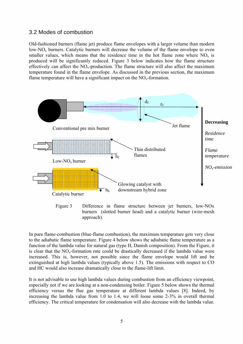
3.2 Modes of combustion Old-fashioned burners (flame jet) produce flame envelopes with a larger volume than modern low-NOx burners. Catalytic burners will decrease the volume of the flame envelope to even smaller values, which means that the residence time in the hot flame zone where NOx is produced will be significantly reduced. Figure 3 below indicates how the flame structure effectively can affect the NOx-production. The flame structure will also affect the maximum temperature found in the flame envelope. As discussed in the previous section, the maximum flame temperature will have a significant impact on the NOx-formation.
Figure 3 Difference in flame structure between jet burners, low-NOx burners (slotted burner head) and a catalytic burner (wire-mesh approach).
In pure flame-combustion (blue-flame combustion), the maximum temperature gets very close to the adiabatic flame temperature. Figure 4 below shows the adiabatic flame temperature as a function of the lambda value for natural gas (type H, Danish composition). From the Figure, it is clear that the NOx-formation rate could be drastically decreased if the lambda value were increased. This is, however, not possible since the flame envelope would lift and be extinguished at high lambda values (typically above 1.5). The emissions with respect to CO and HC would also increase dramatically close to the flame-lift limit. It is not advisable to use high lambda values during combustion from an efficiency viewpoint, especially not if we are looking at a non-condensing boiler. Figure 5 below shows the thermal efficiency versus the flue gas temperature at different lambda values [8]. Indeed, by increasing the lambda value from 1.0 to 1.4, we will loose some 2-3% in overall thermal efficiency. The critical temperature for condensation will also decrease with the lambda value.
Low-NOx burner
Conventional pre mix burner Jet flame
Thin distributed flames
Glowing catalyst with downstream hybrid zone
zf df
hf
hh
Decreasing Residence time Flame temperature NOx-emission
Catalytic burner

6
At too high lambda values it will not be practical possible to implement flue-gas condensation. An upper practical limit would be around lambda=1.4, as shown in the Figure.
0
500
1000
1500
2000
2500
1
1.1
1.2
1.3
1.4
1.5
1.6
1.7
1.8
1.9 2
Lambda value
Adi
abat
ic fl
ame
tem
pera
ture
(ºC
)
Figure 4 Adiabatic flame temperature vs. lambda value. Gas composition: 89.8% C1, 5.8% C2, 2.3% C3, 0.9% C4, 0.3% C5+, 0.7% CO2, 0.3% N2. Calculations performed with Design II (WinSim Corp.)
85
90
95
100
105
110
115
20 40 60 80 100
120
140
160
180
200
Flue gas temperature (ºC)
Ther
mal
effi
cien
cy (%
)
lambda=1lambda=1.4
Figure 5 Thermal efficiency as a function of the flue-gas temperature given at various global lambda values.
Condensing boiler
Typical values

7
If it were possible to decrease the temperature in the flame envelope it should be possible to reduce the NOx-emissions. By implementing a combustion catalyst it is possible to stabilize the combustion process at higher lambda values (avoid flame-lift) and to decrease the gas temperature since the heat produced on the hot catalyst surface is transmitted via thermal radiation. There are a number of phenomena and important design criteria to take into consideration when designing a catalytic burner. The choice of catalyst is of great importance since the thermal impact will be very high. Different catalyst structures have been evaluated as suitable candidates over the years: - Pellets - Foams, ceramic and sintered metal - Fibres, ceramic and metalic - Ceramic monoliths - Metalic monoliths - Wire-mesh structures The catalyst must show a high mass-and heat transfer capacity together with a high intrinsic activity for methane combustion. The catalyst must be able to transmit heat via thermal radiation (i.e. the structure needs to be open). Furthermore, the substrate needs to be mechanically flexible and durable and show a negligible pressure drop. The only substrate, which successfully complies with all these demands, is the wire-mesh concept. By adopting a porous catalytic layer to the wire-mesh structure, it is possible to arrive at a very high catalytic activity. If the catalyst layer is applied according to CATs proprietary technology, the durability and stability of the catalytic layer will be superior as demonstrated by various long-term evaluations and cycling tests [9]. When the pre-mixed gas is led through the catalytic wire-mesh, combustion will be accomplished on the surface and the heat is transmitted to the surroundings via thermal radiation and convection (hot gases). Depending on the surface load (kWt/dm2), we talk about different modes of combustion. At very low loads, typically below 3 kWt/dm2, we talk about pure catalytic combustion, characterized by very low NOx-emissions (typically 1-3 ppmv). When the load is increased, some of the reaction will be conducted in the gas-phase downstream the catalyst. The gas temperature and so the NOx-emissions will increase to some extent. At 8-10 kWt/dm2, we typically see 5-10 ppmv NOx in the flue gases. When the surface load increases, relatively more of the combustion is accomplished in the gas phase. The catalyst temperature will decrease and the flue-gas temperature will increase. The catalyst merely functions as a source for free radicals for gas-phase combustion, i.e. the catalyst stabilizes the combustion process. This domain of combustion is often attributed to as catalytically assisted homogeneous combustion. We normally see 10-15 (20) ppmv NOx in the flue gases and the upper limit for this type of combustion is about 15 kWt/dm2. If the surface load is increased further, blue flames will form over the wire-mesh structure and we are talking about blue-flame combustion. Sine the flames are very thin, the average flame temperature is less than in conventional flames, which means that this mode of combustion also will show rather low NOx-values - typically between 20 and 30 ppmv. Figure 6 below sows the modes of combustion as described above.

8
Figure 6 Different modes of combustion over a wire-mesh catalyst. The wire temperature (catalyst temperature) will vary greatly depending on combustion mode. Emission data have been recorded in various projects over the years. If we plot the NOx-emissions as a function of the surface load we get a rather illustrative picture of this relationship, see Figure 7 below. Most data were recording in combustion of natural gas (type H) and pure methane over CATs proprietary wire-mesh catalyst. The residence time of the hot flue gases in the furnace was limited to less than 100 ms, i.e. we have in all cases utilized compact furnace designs. Traditional furnaces often show higher residence times for the hot flue gases, which might lead to somewhat higher emissions, i.e. a poor boiler design might mask the favourable characteristics provided by the catalytic burner.
0
5
10
15
20
25
0 10 20 30 40
Surface load (kWt/dm2)
NO
x-va
lue
(ppm
v)
#1#2#3#4#5#6#7#8
Figure 7 Recorded NOx-emissions (ppmv) vs.
surface load (kWt/dm2), various test series.
Load, < 3 kWt/dm2 NOx, 1 - 3 ppmv
Catalytic combustion
Hybrid combustion
Heterogeneous assisted
homogeneous combustion
Blue flame combustion
Load, 10-15 kWt/dm2
NOx, 10 - 15 ppmv Load, 3 – 10 kWt/dm2
NOx, 5 – 10 ppmv Load, >15 kWt/dm2 NOx, ≈ 20 ppmv
Catalytic combustion
Hybrid combustion Flameless
oxidation

9
As can be seen in the Figure, all data are located in a narrow corridor, which initially follows a rather linear relationship with the surface load. At about 12 – 14 kWt/dm2, we see a maximum in NOx-emission, typically around 20 ppmv. If the surface load is increased further, the NOx-emission will slowly decrease again, probably due to less residence time (i.e. less time for formation of NOx). This effect is, however, very much dependant on the furnace design, i.e. the correlation will depend on the furnace volume and the temperature profiles within furnace. Too short residence times might lead to increased emissions of CO. Traditionally furnaces are designed to give negligible emissions of CO. A catalytic burner shall preferably be combined with an innovative furnace where the residence time is reduced to very low values. Such a design will also enable us to present a very compact and light-weight burner/boiler-approach. 3.3 Flash back Flash back is a condition where a flame is established at an undesired location upstream the burner nozzle. Apart from giving rise to sound sensations and poor emissions such conditions might damage the burner head. The combustion process is a delicate balance between the flame velocity (depends on the fundamental burning velocity), the flame-port load and the turbulence conditions. In catalytic combustion over a wire-mesh structure, the geometric structure of the mesh is also of importance. The inlet velocity to the burner head must be high enough to cause flame-lift to the surface of the burner, i.e. to the wire-mesh layer. The wire-mesh structure must also be designed in accordance with the minimum quenching distance of the gas mixture (methane-air, typically about 1 mm). The inlet of the burner needs cooling, either by the gas mixture itself or actively by air or cooling water. The presence of hot surfaces adjacent to the gas inlet will indefinitely cause flash-back. The auto ignition temperature of methane is about 500ºC and a surface that hot will stabilize a flame even if the flow rate exceeds the flame velocity [10]. Consequently, the burner head needs to be designed according to three criteria:
a) High inlet velocity to the burner head, typically >5 m/s b) Cooling of inlet section, Tsurf <200ºC c) Utilization of wire-mesh catalyst with high enough mesh no., >20 meshes/inch
If the burner is designed according to these criteria, flash-back can be avoided. The burner can be either cylindrical or flat. In order to shift the catalytic mode to somewhat higher surface loads, it is possible to include a secondary wire-mesh structure (or perforated cylinder) around the primary combustion catalyst. This structure will transfer heat to the wire-mesh catalyst via thermal radiation to circumvent the convective cooling of the air/gas-mixture. In between the combustion catalyst and the secondary structure a hot gas volume is generated, which powers the completion of any gas-phase reactions in a reasonable flame-less mode. By designing around critical distances, residence times and geometrical parameters, it is possible to more or less extinguish the flames and to arrive at flameless oxidation (FLOX), which also is characterized by very low NOx-emissions.

10
In this study, the intention was to use a traditional low-NOx-burner as a backbone for the catalytic burner. The burner consists of an inlet nozzle, a diffuser and a distributor matrix. On top of this we then have a slotted metal cylinder with a number of nozzles for combustion and flame stabilization. A catalytic cylinder is finally added on top of the slotted cylinder. As an alternative, a flat burner design was also tested. Flash-back issues can be a problem, especially in the cylindrical version at part load (surface combustion) since the cooling of the inlet section is poor. The residence time in the furnace is high (≈1 s), which also means that additional thermal NOx can be formed downstream the burner but upstream the boiler sections. 3.4 Durability A number of cycling experiments and long-term evaluations have been performed over the years. The main issues are associated with destructive oxidation of the metal mesh and geometrical disorder following cycling and corrosion phenomena. The wire-mesh consists of FeCrAlloy, which has been very well characterized with respect to destructive oxidation in combustion environment. Figure 8 below shows the life time versus the wire temperature. The maximum wire-mesh temperature is generally obtained at rather low surface loads (ca. 3 kWt/dm2) and does normally not get above 1000ºC. The longevity at 1000ºC exceeds 20,000 hrs of operation. The design target is to show a lifetime of at least 40,000 hrs (calendar time). The accumulated impact following 20,000 hrs at the worst condition should be more harmful to the catalyst than 40,000 hrs of normal cycling.
Figure 8 Longevity vs. wire temperature (ºC), ø 0.5 mm.
10
100
1000
10 4
10 5
0 500 1000 1500
Life
tim
e (h
rs)
Operation temperature (°C)
Operation interval in catalytic burners

11
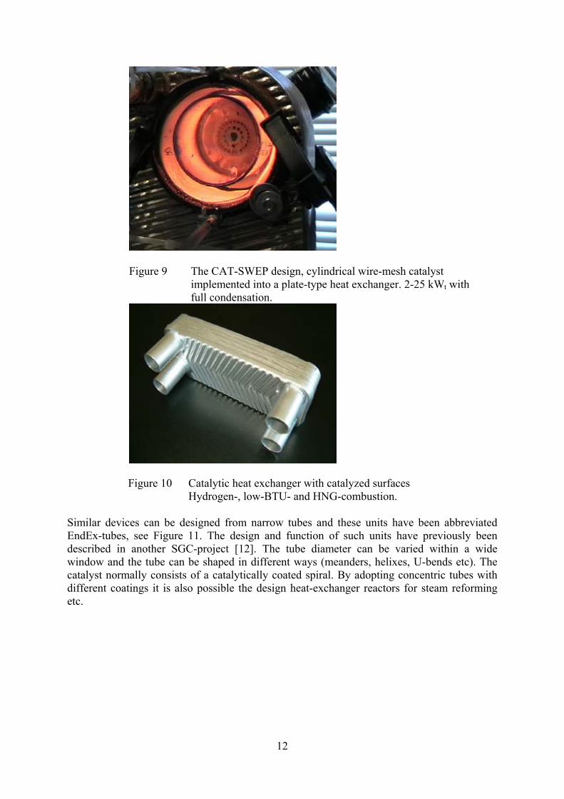
The combustion catalyst is stable to evaporation at these temperatures and will consequently not be affected. A long-term activity study was performed in collaboration with Gaz de France (GdF), where a wire-mesh catalyst was run at a high surface temperature (about 3 kWt/dm2) for over 10,000 hrs without any detected deactivation [11]. The catalyst temperature will normally not exceed about 1000ºC. Additional cycling experiments between 3 and 9 kWt/dm2 were performed in a specially designed cycling rig. In total 300,000 cycles were run without any signs of deactivation. A serious long term deactivation might be associated with corrosion in the rather acidic environment in the boiler, especially when it is condensing. The pH can get as low as 1 – 2, when water evaporates, leaving the acidic components from the odorant behind. This situation can occur during shutdown of a condensing boiler. The results so far let us believe that this problem is possible to handle since we have no evidence for wet corrosion of this kind in our systems under study. It is, however, quite time consuming to accumulate enough time to demonstrate this in practice over 40,000 hrs. Also the ionization probe/ignitor is produced from a similar material and no such problems have been reported for this component. Indeed, this device is located in exactly the same position as the catalytic burner. 4. Previous work CAT has designed and evaluated a number of catalytic burners differing in size, operation conditions and choice of fuels. Catalytic combustion adds a new dimension to combustion since the technology is very flexible with respect to the design and the operation. Indeed, it has been possible to present flexi fuel burners capable of utilizing gaseous as well as liquid fuels in the same design. Burners can be designed as cylindrical or flat units and they can readily be integrated with heat recovery systems. One innovative design has been presented previously and consists of a cylindrical burner, which has been inserted into a plate-type heat exchanger [2], see Figure 9 below. An even more integrated design was proposed in a PhD-project a decade ago [5]. This design was based on catalytic inserts between individual plates. These kinds of units function very well with gaseous fuels, which are easy to ignite like hydrogen and carbon monoxide. During later years we have also presented alternatives were the surfaces of the heat exchanger are coated to get an even closer coupling between combustion and heat recovery. These units can be used in fuel-cell system for combustion of lean gases downstream a fuel cell, see Figure 10 below.
12
Figure 9 The CAT-SWEP design, cylindrical wire-mesh catalyst implemented into a plate-type heat exchanger. 2-25 kWt with full condensation.
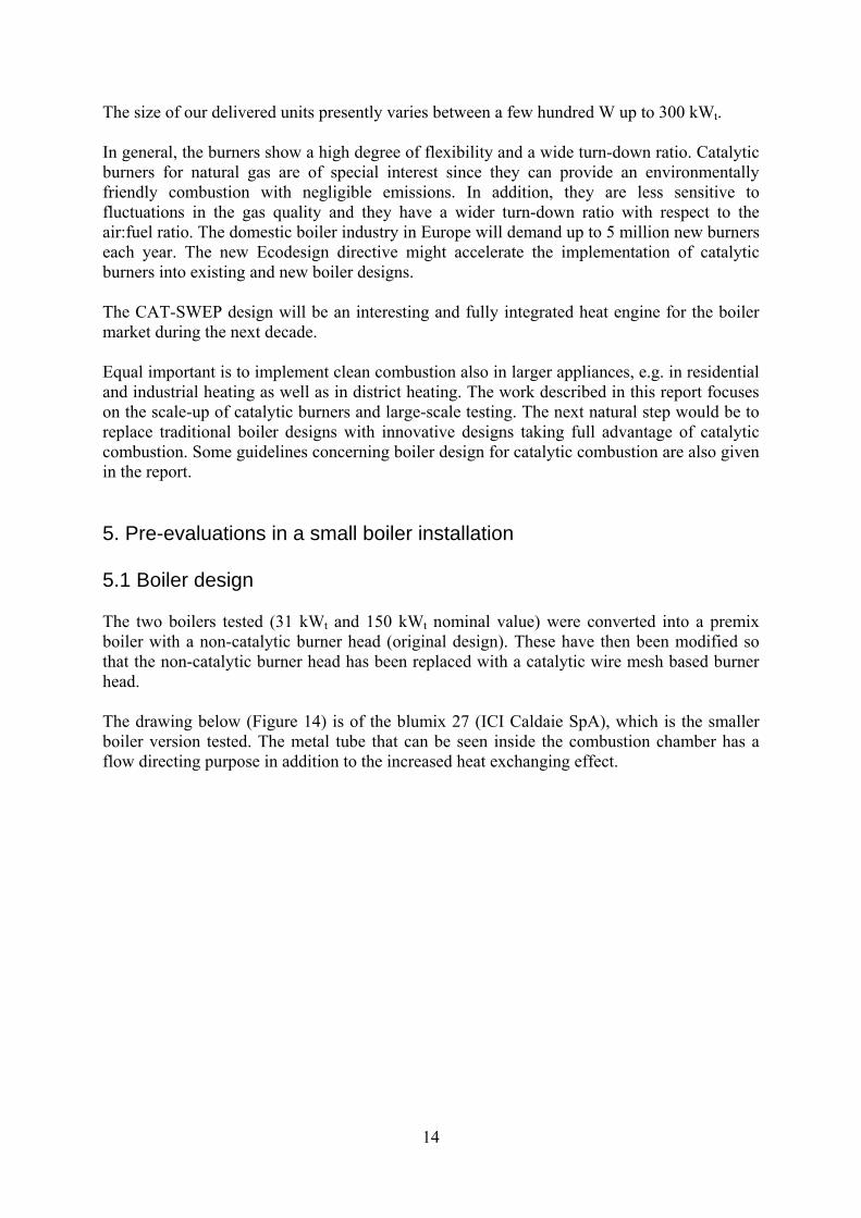
Figure 10 Catalytic heat exchanger with catalyzed surfaces Hydrogen-, low-BTU- and HNG-combustion.
Similar devices can be designed from narrow tubes and these units have been abbreviated EndEx-tubes, see Figure 11. The design and function of such units have previously been described in another SGC-project [12]. The tube diameter can be varied within a wide window and the tube can be shaped in different ways (meanders, helixes, U-bends etc). The catalyst normally consists of a catalytically coated spiral. By adopting concentric tubes with different coatings it is also possible the design heat-exchanger reactors for steam reforming etc.

13
Figure 11 EndEx tubes Flexi fuel burners capable of utilizing fuel gases like natural gas and LPG and low-BTU gases in the same design have been presented in the fuel cell area. Some burners combine the capability of combusting liquid fuels like methanol, ethanol, kerosene and diesel together with low BTU-gases, see Figure 12.
Figure 12 Flexi fuel burner One type of burner works under oxygen starvation with staggered supply of oxygen to avoid runaway reactions (e.g. in stochiometric combustion of hydrogen), see Figure 13 below.
Figure 13 90 kWt catalytic burner for combustion of hydrogen at global lambda=1.
14
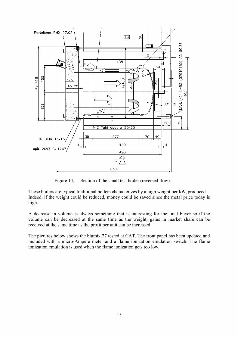
The size of our delivered units presently varies between a few hundred W up to 300 kWt. In general, the burners show a high degree of flexibility and a wide turn-down ratio. Catalytic burners for natural gas are of special interest since they can provide an environmentally friendly combustion with negligible emissions. In addition, they are less sensitive to fluctuations in the gas quality and they have a wider turn-down ratio with respect to the air:fuel ratio. The domestic boiler industry in Europe will demand up to 5 million new burners each year. The new Ecodesign directive might accelerate the implementation of catalytic burners into existing and new boiler designs. The CAT-SWEP design will be an interesting and fully integrated heat engine for the boiler market during the next decade. Equal important is to implement clean combustion also in larger appliances, e.g. in residential and industrial heating as well as in district heating. The work described in this report focuses on the scale-up of catalytic burners and large-scale testing. The next natural step would be to replace traditional boiler designs with innovative designs taking full advantage of catalytic combustion. Some guidelines concerning boiler design for catalytic combustion are also given in the report. 5. Pre-evaluations in a small boiler installation 5.1 Boiler design The two boilers tested (31 kWt and 150 kWt nominal value) were converted into a premix boiler with a non-catalytic burner head (original design). These have then been modified so that the non-catalytic burner head has been replaced with a catalytic wire mesh based burner head. The drawing below (Figure 14) is of the blumix 27 (ICI Caldaie SpA), which is the smaller boiler version tested. The metal tube that can be seen inside the combustion chamber has a flow directing purpose in addition to the increased heat exchanging effect.
15
Figure 14, Section of the small test boiler (reversed flow). These boilers are typical traditional boilers characterizes by a high weight per kWt produced. Indeed, if the weight could be reduced, money could be saved since the metal price today is high. A decrease in volume is always something that is interesting for the final buyer so if the volume can be decreased at the same time as the weight, gains in market share can be received at the same time as the profit per unit can be increased The pictures below shows the blumix 27 tested at CAT. The front panel has been updated and included with a micro-Ampere meter and a flame ionization emulation switch. The flame ionization emulation is used when the flame ionization gets too low.

16
1.
2.
Figure 15 Pictures of the small unit for pre-evaluation tests The 31 kWt boiler tests were performed at CATs premises. Since the boilers are of non-condensing version, it is most important not to use too cold water on the water side of the boiler. Thermocouples were used for temperature measurements and a flow meter was installed to measure the flow. No insulation of the piping was implemented and this will result in some heat losses. This study mainly focuses on the performance of the catalytic burner and the heat recovery efficiency is secondary since this is attributed to the boiler design and has been carefully mapped before. The input fuel effect was calculated from the mass flow rate of natural gas measured during the experiments. The furnace efficiency is associated with the heat balance of the combustion gases when passing through the boiler. The parameters used are the temperature of the premixed gas and the flue gases in combination with the composition of the flue gases. The boiler efficiency also takes possibly thermal losses in the water circuit into consideration. Traditional flame combustion boilers have sensors for measuring the gas ionization, i.e. the current going through the “flame area” when putting a potential to an electrode is measured.

17
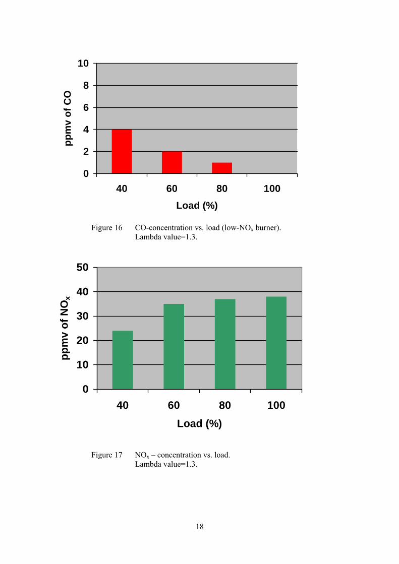
Normal ionization current is in the area of 20 μA and the flame alarm is set at around 2 μA. To measure the ionization current during testing, a micro-Ampere meter was installed. A flame ionization emulation switch was also installed so that testing could be continued if the ionization current got under the 2 μA. This had to be done at lower loads since catalytic combustion is associated with very low ionization signals. When it comes to flue gas emissions and composition the following values were measured: CO (carbon monoxide), CO2 (carbon dioxide), NOx (nitrogen oxides), O2 (oxygen). The O2 gives the lambda value, which is one important parameter in many of the presented graphs. The analyses have been made with the instrument ECOM J2KN. A number of thermocouples were inserted at different positions in the boiler system and the ones of higher relevance are presented later on. 5.2 Design options and results There are really a number of ways to design a catalytic burner. In this study, one intention was to find a way to retrofit the original flame-burner with a catalytic device. Two main design approaches were chosen, a cylindrical burner and a flat burner. The original burner was a slotted metal cylinder comprising a great number of gas nozzles along the surface. These burners provide distributed blue-flame combustion, characterized by very thin flame envelopes and reasonable low NOx-emissions. Other types of low-NOx-burners exist and some are composed by twinned metal fibres. All tests were performed on Danish natural gas [13]. The lambda value was set to 1.3 as a reference value, since the boiler was preset with this value on arrival. When analyzing the flue gases, it could be seen that the emissions were rather good, even with the conventional low-NOx-burner, see Figure 16 and 17 below. The CO-emissions are negligible since the residence time in the gas phase is high enough and no flame impingement occurs on to cold surfaces. In addition, the NOx-emissions are 30 – 40% lower than our expectations for conventional flame combustion. These rather fair NOx-values are attributed to the distributed combustion process comprising very thin flames. The formation of NOx is primarily associated with the flame temperature and the residence time in the hot zone. When reducing the flame temperature and/or the residence time, we shall see a reduction in NOx-formation. Thin flames are normally cooler and the residence time is less than in thick flames originating from traditional flame burners. As can be seen in Figure 17 below, the NOx-emission levels out at about 40 ppmv (air surplus at 30%). At low load conditions, the NOx-level decreases to about 20 ppmv, which is in line with what we normally find in our catalytic heat exchanger at full load [2].
18
0
2
4
6
8
10
40 60 80 100Load (%)
ppm
v of
CO
Figure 16 CO-concentration vs. load (low-NOx burner). Lambda value=1.3.
0
10
20
30
40
50
40 60 80 100Load (%)
ppm
v of
NO
x
Figure 17 NOx – concentration vs. load.
Lambda value=1.3.
19
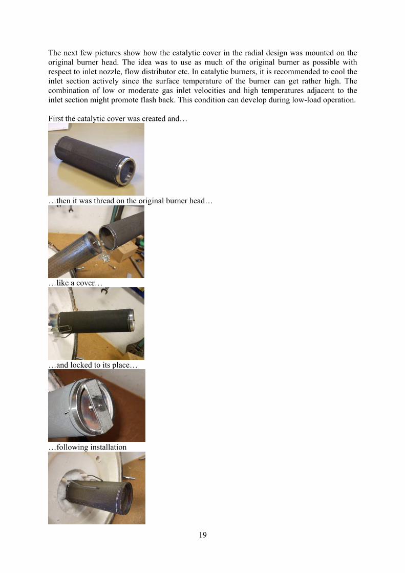
The next few pictures show how the catalytic cover in the radial design was mounted on the original burner head. The idea was to use as much of the original burner as possible with respect to inlet nozzle, flow distributor etc. In catalytic burners, it is recommended to cool the inlet section actively since the surface temperature of the burner can get rather high. The combination of low or moderate gas inlet velocities and high temperatures adjacent to the inlet section might promote flash back. This condition can develop during low-load operation. First the catalytic cover was created and…
…then it was thread on the original burner head…
…like a cover…
…and locked to its place…
…following installation

20
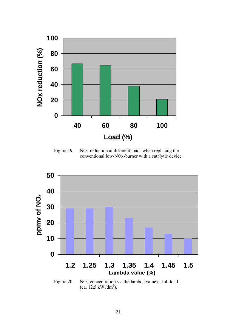
Due to increased surface temperature in catalytic combustion, the original burner head metal became too hot and caused flashback. Thus, data are only recorded at higher loads. Experimental data indicate lower emissions of CO as well as NOx as compared to conventional low-NOx burners. At 20 kWt, the NOx-emission is reduced by 40% whereas the CO-emission is close to zero. If it were possible to go further down in load, we should see an even more dramatic decrease in NOx-emission in catalytic mode. At the highest heat output, the surface load on the wire-mesh catalyst is so high that we approach blue-flame combustion. This also explains why the difference in NOx-emissions between the low-NOx burner and the catalytic burner is smaller at high loads. When relating the observed surface load (kWt/dm2) to NOx-emissions, we obtain a close match between these data and previously obtained data (see Figure 7 in section 3.2). Extrapolation to lower heat loads enables us to forecast NOx-emissions also in the range 5-15 kWt. If we compare data obtained in catalytic combustion with data for the low-NOx-burner, we can obviously demonstrate a NOx-reduction ranging from 20 to 70% over the load interval, see Figure 19 below. All these experiments were run at a lambda value of 1.3. This also means that the NOx reducing potential is even higher since catalytic burners can operate at higher lambda values than conventional burners. In such cases, however, it is important to use condensing boilers in order not to suffer from increased flue gas losses. Figure 20 shows experimentally obtained NOx-data at different lambda values at full load.
0
10
20
30
40
50
40 60 80 100Load (%)
ppm
v of
NO
x
Figure 18 NOx-concentration vs. load (cylindrical catalyst)
Lambda value=1.3
Estimated data
21
0
20
40
60
80
100
40 60 80 100Load (%)
NO
x re
duct
ion
(%)
Figure 19 NOx-reduction at different loads when replacing the conventional low-NOx-burner with a catalytic device.
0
10
20
30
40
50
1.2 1.25 1.3 1.35 1.4 1.45 1.5Lambda value (%)
ppm
v of
NO
x
Figure 20 NOx-concentration vs. the lambda value at full load
(ca. 12.5 kWt/dm2).

22
The planar circular catalytic burner head (axial design) shows some advantages and some disadvantages as compared to the cylindrical catalytic burner head. The most obvious advantage is that the structural strength is much higher. The most important drawbacks are associated with poor flow distribution, risk of overheating of the catalyst manifold (flash back) and problems in positioning the igniter. Figure 21 below shows a picture of the axial burner.
Figure 21 Axial catalytic burner (ø 180 mm) . In this case, the metal tube inside the combustion chamber has to be mounted on the burner head itself due to practical reasons. The holes on the end of the metal tube were an attempt to try to increase the level of radiation in the combustion chamber. Following some initial by-pass problems with high emissions of CO/HC, it was possible to arrive at fair combustion performance with only negligible CO-emissions and acceptable NOx-emissions at low load conditions. At full load, the combustion was in the blue-flame mode, at least at lambda values below 1.4.

23
0
20
40
60
80
100
1.2 1.25 1.3 1.3
5 1.4 1.45 1.5
Lambda value
ppm
v of
NO
x
Figure 22 NOx-emission vs. lambda value at 40 and 100% load.
A CFD-calculation (COMSOL, Chemical Engineering Module) of the NOx-formation was performed on the geometry of Blumix 27 with recorded temperature data for the surfaces inside the furnace, see Figure 23 below. As can be seen in the figure, it should be possible to reduce the NOx-emission by simply reducing the volume of the furnace (i.e. reduction of residence time). Such measures would, however, also involve a careful re-design of the heat recovery surfaces to gain high enough heat transfer and to avoid possible problems with thermal fatigue. The NOx-emissions can also be decreased by increasing the global lambda value in order to reduce the maximum temperature in the furnace. Figure 24 shows the predicted NOx-emission as a function of the global lambda value. Only thermal NOx was considered and the simulations were performed in the turbulent flow regime using the k-ε model. The results should be considered indicative since an accurate prediction of the NOx-levels would need extensive calibration with experimental data. The surface temperatures were taken as the adiabatic flame temperatures, which might exaggerate the NOx-formation – especially at high temperatures were gas-phase radiation might play an increasingly important role.
Flame combustion @ 100% load!
Catalytic combustion @ 40% load

24
Figue 23 Simulation of NOx-formation in Blumix 27 at full load (lambda value =1.3). Concentration is given in ppmv. Burner surface at
the adiabatic flame temperature (1708ºC) and the walls at 100ºC.
1,2
1,25 1,3
1,35 1,4
1,45 1,5
020406080
100120140
ppm
v of
NO
x
Lambda value
Experiments-CATExperiments-LOWCFD
Figure 24 NOx-emission vs. lambda value when combusting natural gas (type
H) at full load in Blumix 27 (Low-NOx-burner and catalytic burner). Comparison between calculations and experimental data.
Burner surface
Symmetry
Cylindrical insert
Wall
ppmv
25
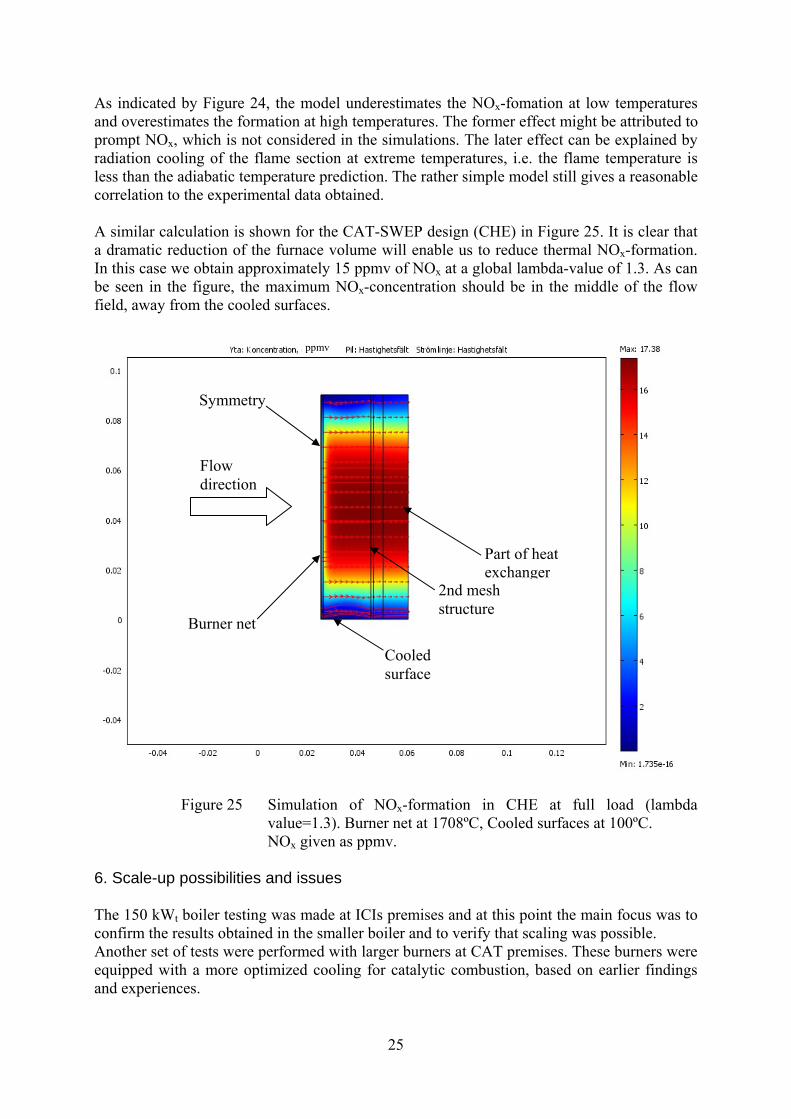
As indicated by Figure 24, the model underestimates the NOx-fomation at low temperatures and overestimates the formation at high temperatures. The former effect might be attributed to prompt NOx, which is not considered in the simulations. The later effect can be explained by radiation cooling of the flame section at extreme temperatures, i.e. the flame temperature is less than the adiabatic temperature prediction. The rather simple model still gives a reasonable correlation to the experimental data obtained. A similar calculation is shown for the CAT-SWEP design (CHE) in Figure 25. It is clear that a dramatic reduction of the furnace volume will enable us to reduce thermal NOx-formation. In this case we obtain approximately 15 ppmv of NOx at a global lambda-value of 1.3. As can be seen in the figure, the maximum NOx-concentration should be in the middle of the flow field, away from the cooled surfaces.
Figure 25 Simulation of NOx-formation in CHE at full load (lambda value=1.3). Burner net at 1708ºC, Cooled surfaces at 100ºC.
NOx given as ppmv. 6. Scale-up possibilities and issues The 150 kWt boiler testing was made at ICIs premises and at this point the main focus was to confirm the results obtained in the smaller boiler and to verify that scaling was possible. Another set of tests were performed with larger burners at CAT premises. These burners were equipped with a more optimized cooling for catalytic combustion, based on earlier findings and experiences.
Part of heat exchanger
2nd mesh structure
Burner net
Cooled surface
Flow direction
Symmetry
ppmv
26
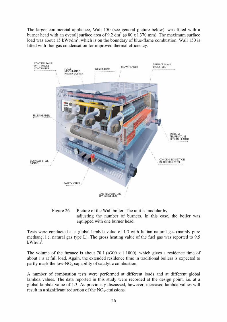
The larger commercial appliance, Wall 150 (see general picture below), was fitted with a burner head with an overall surface area of 9.2 dm2 (ø 80 x l 370 mm). The maximum surface load was about 15 kWt/dm2, which is on the boundary of blue-flame combustion. Wall 150 is fitted with flue-gas condensation for improved thermal efficiency.
Figure 26 Picture of the Wall boiler. The unit is modular by
adjusting the number of burners. In this case, the boiler was equipped with one burner head.
Tests were conducted at a global lambda value of 1.3 with Italian natural gas (mainly pure methane, i.e. natural gas type L). The gross heating value of the fuel gas was reported to 9.5 kWh/m3. The volume of the furnace is about 70 l (ø300 x l 1000), which gives a residence time of about 1 s at full load. Again, the extended residence time in traditional boilers is expected to partly mask the low-NOx capability of catalytic combustion. A number of combustion tests were performed at different loads and at different global lambda values. The data reported in this study were recorded at the design point, i.e. at a global lambda value of 1.3. As previously discussed, however, increased lambda values will result in a significant reduction of the NOx-emissions.

27
Figure 27 shows the CO- and NOx-emissions from the tests in Wall 150.
40 100CO
NOx0
1020
30
40
50pp
mv
of C
O, N
Ox
Load (%)
CONOx
Figure 27 CO-and NOx-emissions obtained at a lambda value of 1.3 in
Wall 150.
The tests performed at CATs premises with Blumix 27 showed NOx-emissions in the region 20 – 30 ppmv and negligible CO-emissions. In this case of Wall 150 we obtain about 25% higher NOx-emissions whereas the CO-emissions are very low. The relatively higher NOx-emission can be attributed to the design and the operation of the boiler. Careful analysis involving CFD-modeling let us believe that the residence time in the hot environment is somewhat higher as compared to Bluemix27 and certainly in comparison to the CHE-concept. A way to decrease the NOx-formation is to increase the lambda value. This measure will affectively decrease the peak temperature in the combustion zone and also reduce the residence time at a certain load. Complementary tests were performed at CAT with actively cooled catalytic burners. The first burner head had a cylindrical design and operated in the transition between catalytic and hybrid combustion, i.e. ranging between 3 kW/dm2 and 15 kW/dm2. The burner was equipped with a secondary radiation shield and a cooling coil adjacent to the radiant surface, see picture 28 below. The inlet section (nozzle section) and the end plates were actively cooled to prevent flash back.
28
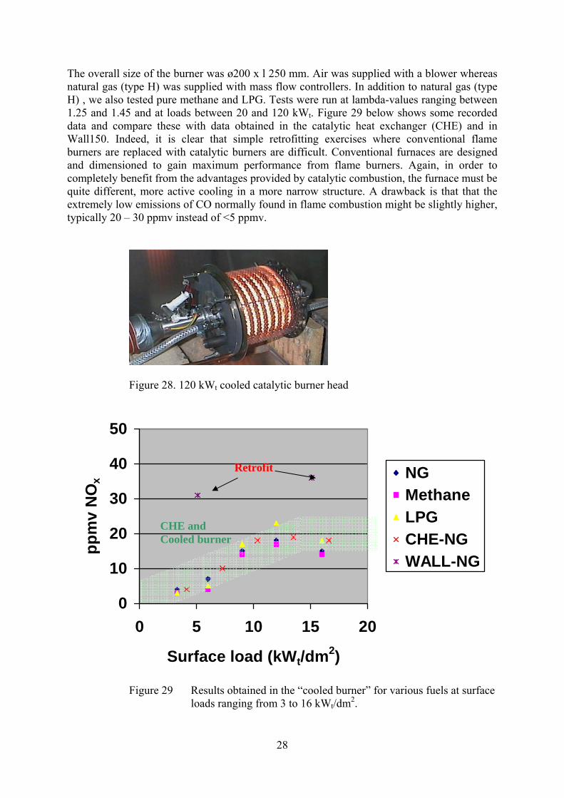
The overall size of the burner was ø200 x l 250 mm. Air was supplied with a blower whereas natural gas (type H) was supplied with mass flow controllers. In addition to natural gas (type H) , we also tested pure methane and LPG. Tests were run at lambda-values ranging between 1.25 and 1.45 and at loads between 20 and 120 kWt. Figure 29 below shows some recorded data and compare these with data obtained in the catalytic heat exchanger (CHE) and in Wall150. Indeed, it is clear that simple retrofitting exercises where conventional flame burners are replaced with catalytic burners are difficult. Conventional furnaces are designed and dimensioned to gain maximum performance from flame burners. Again, in order to completely benefit from the advantages provided by catalytic combustion, the furnace must be quite different, more active cooling in a more narrow structure. A drawback is that that the extremely low emissions of CO normally found in flame combustion might be slightly higher, typically 20 – 30 ppmv instead of <5 ppmv.
Figure 28. 120 kWt cooled catalytic burner head
0
10
20
30
40
50
0 5 10 15 20
Surface load (kWt/dm2)
ppm
v N
Ox NG
MethaneLPGCHE-NGWALL-NG
Figure 29 Results obtained in the “cooled burner” for various fuels at surface loads ranging from 3 to 16 kWt/dm2.
Retrofit
CHE and Cooled burner

29
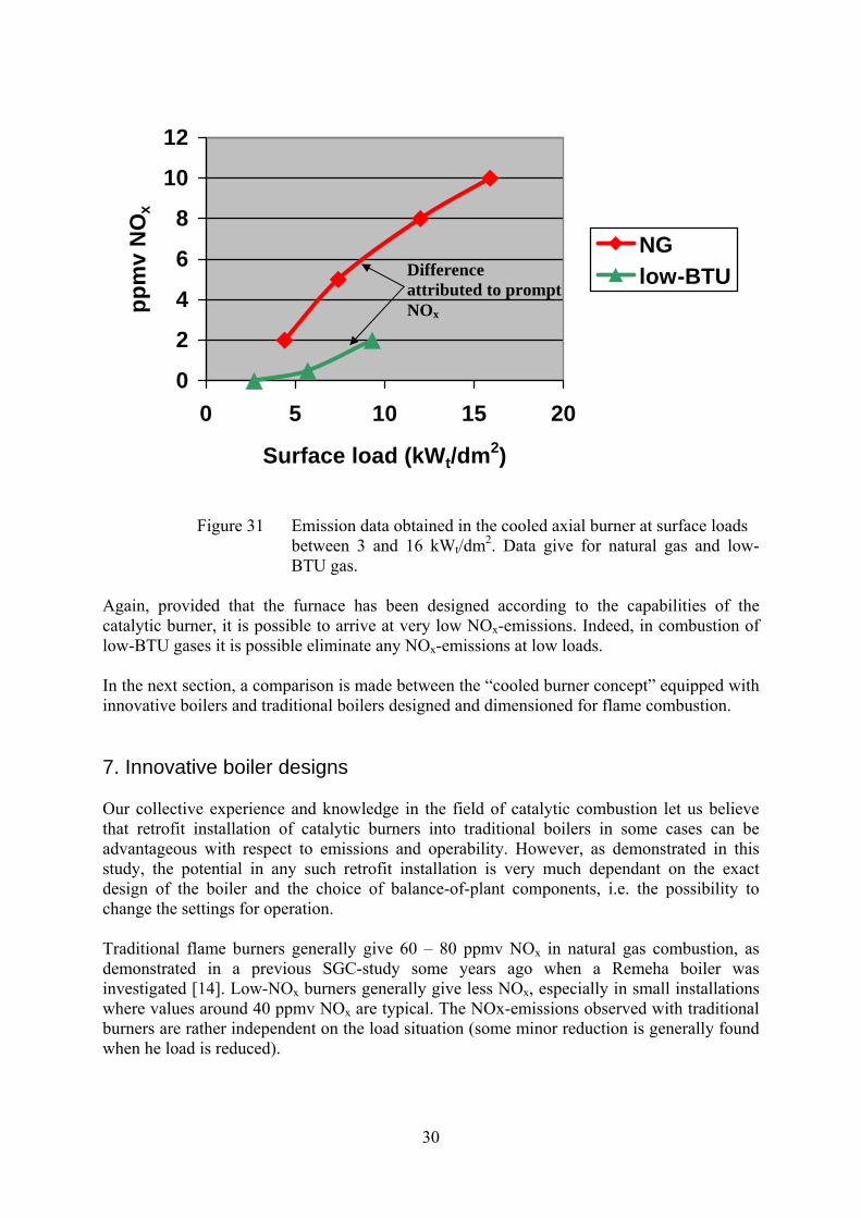
As can be seen in the Figure, there is no significant difference between combusting natural gas (type H), methane or LPG. Thus the same general type of burner can be used for all type of fuels. It is also quite clear that active cooling has a positive effect on the emissions of nitrogen oxides. In addition, flash-back does not occur if sections adjacent to the nozzle/distributor are cooled. Even if the cooled burner is a laboratory prototype it provides important information concerning the possibilities with catalytic combustion, provided that the cooling of the burner is correctly designed and dimensioned. A complete 150 kWt furnace with an axial burner was also designed and tested for its performance, see figure 30-31 below. The maximum surface load was about 16 kWt/dm2at full thermal load (150 kWt). Addition of flue-gas condensation should improve the thermal output by more than 15%.
Figure 30 Cooled axial burner equipped with a burner head comprising a Ø310 mm wire mesh disc contained in a secondary radiating
structure.
The unit was tested with pure natural gas (type H) as well as low-BTU-gas since similar units are used in fuel-cell systems for tail-gas combustion. Reformate and tail-gas contains hydrogen and carbon monoxide in addition to methane.
Combustion air
Fuel
Exhausts
Coolant
30
0
2
4
6
8
10
12
0 5 10 15 20
Surface load (kWt/dm2)
ppm
v N
Ox
NGlow-BTU
Figure 31 Emission data obtained in the cooled axial burner at surface loads
between 3 and 16 kWt/dm2. Data give for natural gas and low-BTU gas.
Again, provided that the furnace has been designed according to the capabilities of the catalytic burner, it is possible to arrive at very low NOx-emissions. Indeed, in combustion of low-BTU gases it is possible eliminate any NOx-emissions at low loads. In the next section, a comparison is made between the “cooled burner concept” equipped with innovative boilers and traditional boilers designed and dimensioned for flame combustion. 7. Innovative boiler designs Our collective experience and knowledge in the field of catalytic combustion let us believe that retrofit installation of catalytic burners into traditional boilers in some cases can be advantageous with respect to emissions and operability. However, as demonstrated in this study, the potential in any such retrofit installation is very much dependant on the exact design of the boiler and the choice of balance-of-plant components, i.e. the possibility to change the settings for operation. Traditional flame burners generally give 60 – 80 ppmv NOx in natural gas combustion, as demonstrated in a previous SGC-study some years ago when a Remeha boiler was investigated [14]. Low-NOx burners generally give less NOx, especially in small installations where values around 40 ppmv NOx are typical. The NOx-emissions observed with traditional burners are rather independent on the load situation (some minor reduction is generally found when he load is reduced).
Difference attributed to prompt NOx

31
A catalytic burner will behave similar as a traditional low-NOx burner in the blue-flame mode, but will enable significant turn-down effects on the NOx-emissions. In addition, catalytic burners can operate at higher lambda values and they also show a more narrow flame envelope. The latter characteristic makes it possible to reduce the distance between the surface of the burner and the cooling surfaces without flame impingement and detrimental CO-emissions. A number of advantages can be achieved if the boiler is designed around the catalytic burner:
a) Extremely low NOx-emissions, < 15 ppmv at full load b) Reduced size & weight of the installation = less production cost c) Increased thermal efficiency
High thermal efficiency and low NOx-emissions will put any such device in the frontier of the boiler technology. Simultaneously, which is important for the manufacturer, the material expenses can be significantly reduced. The CHE-unit, previously discussed is an innovative design, which will comply with all these items. It is, however, only available for small domestic appliances (currently about 30 kWt). Similar design approaches with or without plate-type heat exchangers should be investigated in larger heating appliances and for steam production. CATs proprietary wire-mesh technology and methods to catalyze hardware (body fitted catalysis) is highly flexible to any geometric demands. The Figure below shows the potential in reducing the size and weight of a large appliance when adopting catalytic combustion.
Figure 32 Size comparison between a traditional burner/boiler and an innovative heat-exchanger boiler equipped with a catalytic burner.
Conventional Burner/boiler 100 – 300 kWt/m3
Innovative CatBurn/boiler > 1 MWt/m3

32
Typical volume effects found for modern commercial units in the effect class 200 – 1000 kWt are between 100 and 300 kWt per m3 of gross volume [15-17]. We have previously discussed and demonstrated the possibility to scale the catalytic burner technology. It is possible to present effect densities as high as 7 MWt/m3 (even 10 MWt/m3) of burner/boiler with the innovative CHE-design. In addition to the burner/boiler-volume there are a number of auxiliary components and electronics to contain. A careful evaluation let us believe that it should be possible to present a complete condensing unit with an effect density of about 1000 kWt per m3 of gross volume. The size reduction makes it easier to handle and install the unit. In parallel to this, the weight will be greatly reduced. The NOx-emission will comply with the Ecodesign criterion and the thermal efficiency in the condensing device will be above 105% (LHV). An additional advantage with catalytic combustion is that the technology is insensitive to variations in the gas quality. Indeed, the same technology might be used in combusting natural gas (H/L), biogas, LPG, HNG/Hythane and even liquid fuels. This would then mean that the number of different versions of burner/boiler designs can be reduced and replaced with a generic platform. 8. Conclusions and future work From the tests is clear that catalytic combustion can decrease the emissions of NOx to various degrees, depending on the operation conditions and different design features. If the NOx-emissions are plotted against the surface load, we see a deviation from previous work with compact boiler designs. Indeed, the extended residence time in the furnane will contribute to additional production of NOx. The most effective way to further decrease the NOx-emission is thus to reduce the volume of the furnane. In the present design, it is possible to arrive at NOx-emissions in the range of 20 to 30 ppmv with negligible emissions of CO and hydrocarbons. To further decrease the emissions, it is also advisable to increase the lambda value somewhat and to implement flue-gas condensation for increased thermal efficiency. The cooling of the burner head needs to be improved in order to avoid flash-back situations at low surface load (pure catalytic combustion). To further simplify the boiler design, it is recommended to use a one-pass flow configuration instead of a reversed flow design. The study clearly shows the importance to design the boiler around the furnace instead of retrofitting an innovative burner into a traditional furnace/boiler. In retrofit installation, the benefits of the innovative burner will be masked by the characteristics of the furnace. A natural continuation of this work will be to present an innovative furnace design suitable for catalytic combustion and to construct and demonstrate this.

33
9. Literature 1. F. Silversand, EP 0871 543 2. F. Silversand, Catalytic heat exchangers – a long term evaluation, SGC-report
no. 140, Swedish Gas Centre 2003. 3. Eco-design Directive for Energy Using Products, 2005/32/EC, Lot 1 & Lot 2. (CH-boilers and Water heaters) 4. F. Silversand, Fuel Processor for small-scale production of hydrogen –
Experimental study, SGC-report no.139, Swedish Gas Centre 2003. 5. F. Silversand, Catalytic Combustion in Energy Production and Environmental
Protection, Doctoral thesis, Lund University 1996, sid. 44. 6. H. Edner, G. Holmstedt, S. Wallin, Bildning och begränsning av NOx vid
naturgasförbränning, Stiftelen för Värmeteknisk Forskning, Stockholm 1985. 7. M. Grimsberg, Formation of Nitrogen Oxides during Combustion, Licentiate
thesis, Lund University, 1990, p. 2 8. Industriell Naturgasteknik, Styrelsen för teknisk utveckling, info. nr. 702-1988 Stockholm 1988, ISBN 91-7850-272-1, sid 44 9. A.-K. Jannasch, F. Silversand, E. Tena, M. Berger, Development of a novel
catalytic burner for natural gas combustion for gas stoves and cooking plate applications, Catalysis Today, 117, 433 (2006).
10. F. P. Lees, Loss Prevention in the Process Industry, Butterworth-Heinemann Ltd, Oxford 1980, sid. 488.
11. A.-K. Hjelm, F. Silversand, E. Tena, M. Berger, Development of Catalytic Coking plates, SGC-report. no. 145, Swedish Gas Centre 2004.
12. A.-K. Jannasch, Utveckling av katalytisk rörbrännare för naturgasförbränning för luftuppvärmning i matlagningsugn, SGC-report nr. 158, Swedish Gas Centre 2005.
13. www.dgc.dk 14. F. Silversand, Evaluation of three-way catalysis for NOx-abatement in large gas-
fired appliance, SGC-report no. 104, Swedish Gas Centre 1999. 15. Information material, ICI Caldaie, GreeNOx.e 47 @ 470 kWt 16. Information material, Remeha, Gas 310 ECO, 106-531 kWt 17. Information material, Veissmann, Vitocrossal 200,135-628 kWt

Scheelegatan 3, 212 28 Malmö ● Tel 040-680 07 60 ● Fax 040-680 07 69www.sgc.se ● [email protected]