rapid tooling development - intech -...
TRANSCRIPT

3
Rapid Tooling Development
Sadegh Rahmati Islamic Azad University (IAU) – Majlesi Branch
Iran
1. Introduction
Now a days, rapid prototyping (RP) technology is commonly used to quickly realise the conceptualization of a product design by creating prototypes. These prototypes allow designers and engineers to visualise potential problems, and to implement different solutions in the early product design stages. These prototypes may be used in different industries such as aerospace, aeronautics, automobile, home appliances, industrial equipment, electronic devices, etc. The selection of the suitable RP technique for the manufacturing of a certain product is a very complex problem and depends on several factors (Chen and Cheng, 2000). Rapid tooling (RT) provides a significant increase in speed and reduction in cost, while for small production runs and complex objects, RP is often the best manufacturing technique available (Ilyas et al., 2010). Moreover, RP, RT and Rapid Manufacturing (RM) techniques can also be used to rapid manufacture parts with excellent quality (Quail et al., 2010; Campbell, et al., 2011). Currently, companies are experiencing increasing pressure to produce complex and diverse products in shorter product development cycles, aiming to achieve less overall cost with improved quality (Evans and Campbell, 2003). As delivery time and cost of products are on a downward trend, the modern mould manufacturers are increasingly more under pressure to produce moulds quickly, accurately, and at lower cost. Evidently, rapid prototyping and rapid tooling have shortened time to produce a physical prototype or tool. Hence, RP, RT and RM are playing an increasingly significant role in responding to intense global markets competition and achieving compressed time-to-market solutions (Bibb et al., 2009). In order to investigate the success of rapid tooling technology, two case studies are presented and analysed in this chapter. The first case study is the development of stereolithography (SL) tooling for short run plastic injection mould tooling. The second case study is dealing with development of rapid wax injection mould tooling to be used for investment casting process.
2. Stereolithography rapid tooling
In the first case study the development of stereolithography (SL) tooling for short run plastic injection mould tooling is investigated. As manufacturing industry encounters a growing demand for rapid tooling, RP technology in particular stereolithography tooling has demonstrated to have significant potential in product and tool development. However, among different tooling processes, the process of rapid plastic injection mould tooling is
www.intechopen.com
Rapid Prototyping Technology – Principles and Functional Requirements
56
significantly critical for the industry. Compared to still higher resolving techniques, stereolithography bears the advantages of short processing times and good surface finish. Tool makers and manufacturers usually describe the performance of their devices in terms of accuracy or minimal layer thickness, and minimal surface roughness achieved. Due to the fact that stereolithography has obtained a resolution as high as 60 μm, this significant advance in resolution enables stereolithography to build insert components with improved performance. High performance stereolithography resins, minimum layer thickness of 0.06 mm, minimum surface roughness of 4 μm, and nearly zero shrinkage, has made SL an ideal candidate for rapid tooling purposes. Consequently SL tooling techniques are improving and are becoming increasingly popular among manufacturers (Decelles & Barritt, 1996; Greaves, 1997; Jacobs, 1996). During the last few years, significant research and developments are achieved by different research groups which have worked on rapid tooling issues. Weiss has demonstrated that a rapid prototype model can be used as a master to get a shell of metal and with a supporting material such as epoxy resin, it can be used for injection moulding, metal forming and EDM electrode (Weiss et al., 1990). Paul Jacobs has discussed the non-homogeneous mechanical property of SL models. He showed that the mechanical property of SLA models are a function of laser exposure and prior knowledge about it can help to reduce the shrinkage generated distortion during part building process and post curing operation (Jacobs, 1992). Gargiulo carried out an experiment with various hatch styles to improve part accuracy of stereolithography (Gargiulo, 1992). Richard discussed the effects of parameters on the accuracy of parts built by SL process (Richard, 1993). Rahmati and Dickens developed a series of experiments to demonstrate the performance of SL rapid tooling to utilise them as injection moulding tools (Rahmati & Dickens, 1997). In this case study, the SL injection mould has been analysed using different CAE simulation softwares. In particular, MoldFlow is used to get plastic injection moulding parameters such as speed, and pressure. Next, ANSYS software is utilised to investigate the forces exerted on different features of the inserts and to investigate the locations of stress concentration during injection cycle. The result of MoldFlow and ANSYS software analysis demonstrates and confirms the practical results, and assures the possibility of using stereolithography rapid tooling for batch production. Previous work at Nottingham University has shown that SL injection mould tooling can be used successfully in low to medium shot numbers (Rahmati & Dickens, 2005). Previous work included the tool experimental procedure, testing mechanical properties of the epoxy resin on tensile and impact strength, tool temperatures studies, and tool injection pressure analysis. However, this work is focusing on development of simulation and analysis of SL rapid tooling, where the SL injection mould has been analysed using MoldFlow to get plastic injection parameters such as speed, and pressure. The forces exerted on different features of the insert are calculated and utilised at ANSYS to investigate the stress concentration locations.
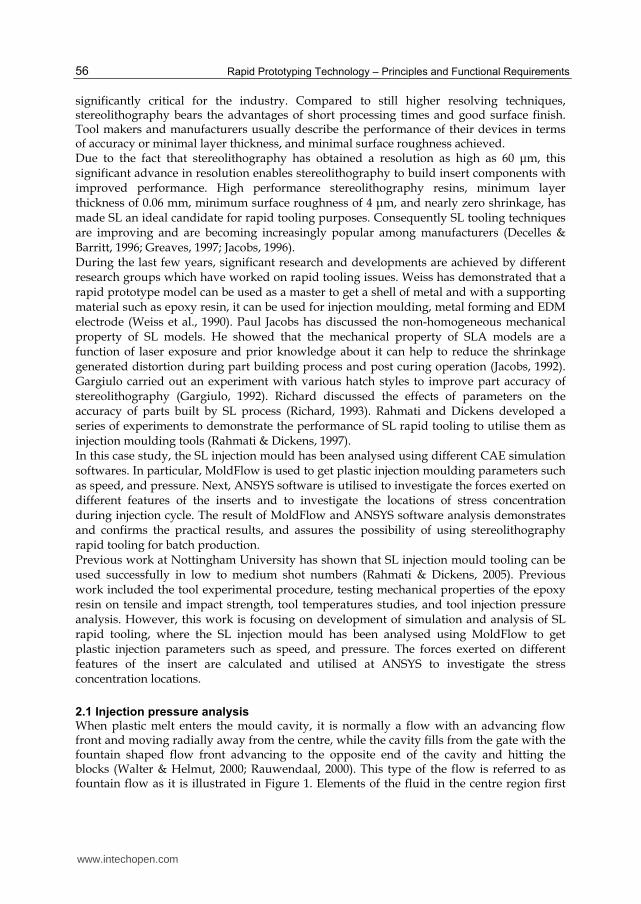
2.1 Injection pressure analysis When plastic melt enters the mould cavity, it is normally a flow with an advancing flow front and moving radially away from the centre, while the cavity fills from the gate with the fountain shaped flow front advancing to the opposite end of the cavity and hitting the blocks (Walter & Helmut, 2000; Rauwendaal, 2000). This type of the flow is referred to as fountain flow as it is illustrated in Figure 1. Elements of the fluid in the centre region first
www.intechopen.com
Rapid Tooling Development
57
decelerate as they approach the flow front, then the elements start to move tangentially towards the wall. The wall is relatively cold and a frozen skin layer will form behind the advancing flow front. The elements in the flow front are stretched as they move from the centre towards the wall. The fountain flow mechanism is responsible for a high degree of orientation of the surface layers of the moulded product. This is due to the stretching of the fluid elements approaching the wall while cooling occurs at the wall. The cooling rate is much slower as moving away from the wall and as a result, more relaxation can occur inside the material. Many studies have confirmed significant gradients in orientation and morphology from the outside layers to the inside of injection moulded parts.
Fig. 1. Illustration of fountain flow into a mould cavity (Rauwendaal, 2000)
The flow loses heat and pressure as it moves away from the centre and in addition to this
pressure loss, the flow moving upwards faces additional loss due to the bends. There are
two main forces acting on the blocks, one due to the shear stress acting on the base, the other
is the bending stress trying to tip over the blocks. In general, at any instant where the
injection pressure is higher than the tool strength, failure is feasible. To avoid this, care is
taken to inject at a temperature where the tool has sufficient strength. This criteria has led to
a well defined cycle, where injection always takes place when the tool temperature has
dropped to 45oC, where the material’s strength and toughness is able to resist the injection
pressure. Stresses exerted on the cavity are dependent on parameters such as melt velocity,
and injection pressure.
2.2 MoldFlow & ANSYS fundamentals
According to the principle of continuity which is based on the mass conservation, the mass of melt entering at a control volume in unit time is equal to the mass leaving (Fig. 2).
.
. 0c v
dv dAt v
(1)
Thus the equation of mass conservation by integral is derived. Now the differential presentation of the above is given as:
.( ) 0p
V p vt
(2)
www.intechopen.com

Rapid Prototyping Technology – Principles and Functional Requirements
58
Here, V is the velocity of the fluid, A is the control area, is mass volume, v is the control
volume, p is the pressure, and t is the time. Then the continuity equation is simplified for
special case of incompressible fluid ( )cont .
.
.
. 0c v
c s
dv v d At
(3)
Fig. 2. Rectangular element within the enclosed volume
Integral presentation of the Newton second law of motion is given as follows:
. .
.S B
c v c v
F F F v dv v v d At
(4)
This states that the sum of body force and surface force is equivalent to the change of
reference volume plus net motion leaving the reference volume. Here, sF is the shear force,
and BF is the normal force. F is the sum of effective external forces on the reference
volume. It is possible to expand this equation in any desired direction. Differential
presentation of this equation, assuming and to be constant, is known as Navier-Stokes
equations. Hence, Euler's equation along the streamline for a steady flow, regardless of
volume forces is given as follows:
1 P v
vs s
(5)
When the Euler's equation is integrated along the streamline, Bernoulli's equation is obtained as follows:
2
2
P vgz const (6)
When applying the above equation, one of the two assumptions must be satisfied: equation is given along the streamline, the flow is irrotational. Since the polymer melt flow in the cavity is rotational, thus Euler's equation must be applied along the streamline. Fig. 3
www.intechopen.com
Rapid Tooling Development
59
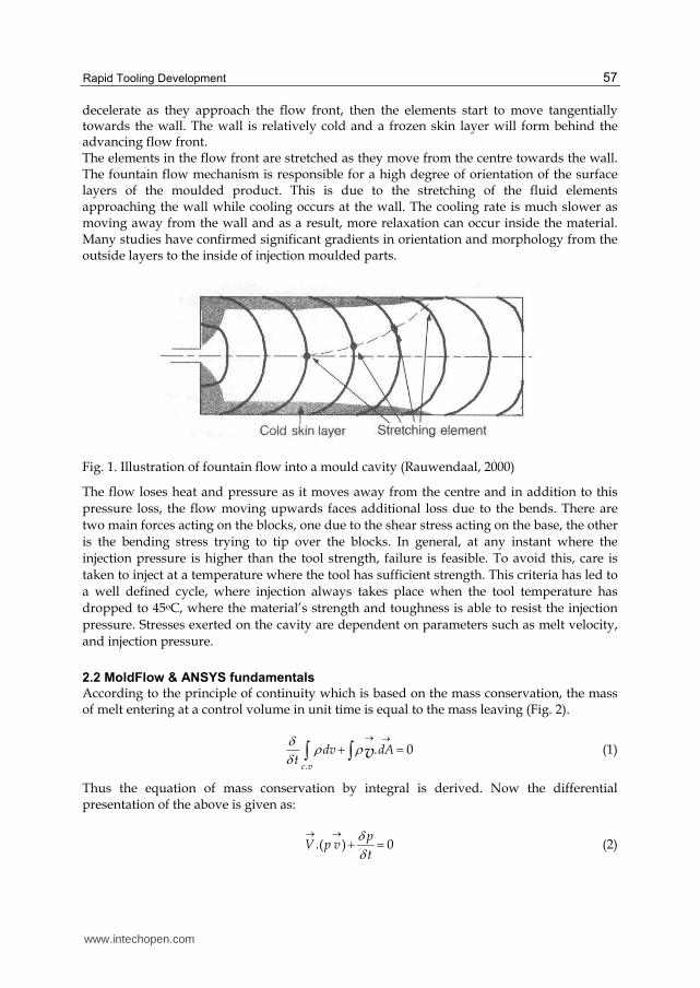
illustrates the flow between two parallel plates at a distance of 'a', where the flow is developed as lamina, steady, and incompressible.
Fig. 3. Flow between parallel plates
Solving the Bernoulli's equation for the above situation, velocity distribution and shear stress distribution for the flow within the parallel plates is obtained.
2
2( ) ( ) ( )2
y ya Pv
x a a (7)
1
( )( )2
yx
ydu Pa
dy x a (8)
Moreover, flow rate passing within two parallel plates is given as follows:
3
31( )
12 12
P a PQ a
x L (9)
Here L is the melt path length. Applying the continuity equation, the forces exerted over the cube surfaces (Fig. 4) is calculated as follows:
1 1 2 2 1 1 1 2 1( ) ( ( ) )nF P A P A Cos V A V Cos V (10)
2 2 1 1 1 2( ) ( ( ))sF P A Sin w V A V Sin (11)
Fig. 4. Schematic representation of flow continuity
www.intechopen.com

Rapid Prototyping Technology – Principles and Functional Requirements
60
Here nF and sF are the normal force and shear force respectively, 1P and 2P are the
primary and secondary pressure respectively, 1A and 2A are the primary and secondary
area respectively, 1V and 2V are the primary and secondary velocity respectively, and is
the melt path angle with respect to horizon.
2.3 Simulation results of MoldFlow
First, the part is designed three dimensionally using the geometrical dimensions shown in
Fig. 5. The applied SL injection mould consists of different hollow cubes varying of
dimension in the X, Y, and Z axes, i.e. two 10x10x10mm cubes, two 10x9x10mm, two
10x8x10mm, and two 10x7x10mm cubes, all located symmetrically. Then the created
3D model is entered into the MoldFlow software. Next the model is meshed using the
FUSION style.
When a 3D volume mesh is created, Moldflow Plastics Insight (MPI) first creates a Fusion
mesh from the input file. Then any defects present in the Fusion mesh must be corrected and
meshed again using the Generate Mesh dialog. This time, MPI will create the 3D mesh.
Fusion works by simulating the flow of the melt on both the top and bottom parts of the
mould cavity. Consistency between the results on the opposite sides is maintained by using
"connectors" - elements with zero flow and heat resistance. The connectors are inserted
automatically at locations determined according to the geometrical features of the model.
Fig. 5. Geometrical dimensions of the moulding
Next the moulding material is chosen. The material chosen for the MoldFlow analysis has
the properties and characteristics, as given in Table 1, and therefore the results of MoldFlow
analysis of injection parameters are calculated and presented in Table 1. Now it is possible
to analyze the best choice for sprue location, which the result is presented in Fig. 6 in color.
As shown in Fig. 6, the best gate location as expected is at the middle of the moulding. After
deciding on the gate best location, FILL analysis is carried out.
www.intechopen.com

Rapid Tooling Development
61
Table 1. Moulding material properties and injection parameters results
Fig. 6. MoldFlow analyses for sprue bush location
Fig. 7. The identification number of each edge of a cube
Material data: POLYPROPYLENES (PP) Material structure: Crystalline Melt density: 0.72848 g/cm^3 Solid density: 0.90628 g/cm^3 Specific heat (Cp): 3000.0000 J/kg-C Thermal conductivity: 0.1500 W/m-C Fill time: 2.1000 s Cooling time: 20.0000 s Velocity/pressure switch-over: Automatic Packing/holding time: 10.0000 s
www.intechopen.com

Rapid Prototyping Technology – Principles and Functional Requirements
62
The purpose of the FILL analysis is to investigate the pressure and velocity for choosing
interested location for cavity. Therefore the result of the FILL analysis about Time at the end
of filling is 2.4184s and Total moulding weight is 20.4960 and required clamping force is
13.9166 tones. Comparing the filling time of 2.2 sec resulted from FUSION mesh in Table 1,
with the result of FILL analysis of 2.4184 sec, 0.2184 sec difference is due to the fact that FILL
analysis has taken the mass of melt including the sprue bush.
Next, the velocity at the edge of the cubes as identified in Figure 7, is analysed. The melt
velocity at different cube locations is presented in Table 2 in terms of cm/sec. Due to the
fountain effect of melt flow into the cavity, the maximum melt velocity is randomly
assigned to one of the cubes in each run of the FILL analysis. However, in order to account
for the critical situation, the velocity on edge 8 is assumed to be zero, because the failure
may happen while there is a maximum differential pressure build up between the front side
and back side of the cubes.
Edge 1 2 3 4
Velocity 91.56 48.38 88.59 98.64
Edge 5 6 7 8
Velocity 14.52 76.5 65.36 19.3
Table 2. Velocities of all edges of a cube in cm/sec
According to the fountain flow behavior of the polymer melt into the cavity, velocities are determined as shown in the Table 2. It is observed that on edge 4 (Fig. 7) which the melt front hits first, the velocity is maximum, while the velocity on the other edges is less. Subsequently, the pressure at all cube edges is determined as in the Table 3 in terms of MPa.
cube1 cube2 cube3 cube4
Edge1 (MPa) 15.89 16.63 16.25 14.91
Edge2 (MPa) 15.21 15.96 15.73 14.55
Edge3 (MPa) 15.03 15.71 15.36 14.05
Edge4 (MPa) 15.53 16.07 15.57 14.02
Edge5 (MPa) 14.34 15.19 15.28 14.12
Edge6 (MPa) 14.38 15.11 14.9 13.65
Edge7 (MPa) 13.11 15.39 14.97 13.54
Table 3. Pressure of all edges of a cube in MPa
Pressure gradients exerted on each surface is derived from the pressure changes of its edges. Due to the fact that larger surface refers to the bigger cube; subsequently larger pressure changes are expected to happen on bigger cube as well. Accordingly, decreasing pressure
www.intechopen.com

Rapid Tooling Development
63
differential trend is expected on the subsequent cubes. Now, with regard to the results obtained from the MoldFlow software and the following fluid dynamics relationships, the forces exerted on each cube is extracted.
Fig. 8. The identification number of each face of a cube
Due to the fact that only the critical situations are of interest in this analysis, therefore only
the maximum differential pressures have been taken into consideration, as presented in
Table 4. This table is presenting the normal and shear forces (Fn, Fs) which exists on the cube
surfaces shown in Figure 8, where surface "A" is the front face, surface "B" is the left side
face, surface "D" is the right side face, and surface "C" is the top face of the cube.
CUBE1 A B C D
Fn (N) 266.08 255.36 0 257.12
Fs (N) 224.8 225.92 218.4 209.76
CUBE2 A B C D
Fn (N) 232.82 223.44 0 224.98
Fs (N) 196.7 197.68 191.1 183.54
CUBE3 A B C D
Fn (N) 199.56 191.52 0 192.84
Fs (N) 168.6 169.44 163.8 157.32
CUBE4 A B C D
Fn (N) 166.3 159.6 0 160.7
Fs (N) 140.5 141.2 136.5 131.1
Table 4. Forces exerted on each surfaces of cubes (N)
2.4 Simulation results of ANSYS
Now considering the forces obtained from fluid analysis, the core side of the mould is analyzed using ANSYS software for stress investigation. Due to the fact that the mould is designed to be symmetric (Fig. 5), therefore the ANSYS analysis is carried out only for half of the tool (Fig. 9). The 3D model generated, is entered into the ANSYS software. Next the model is meshed using the SOLID95 style which is compatible with three dimensional displacements resulted from the force exerted by melt pressure. SOLID95 mesh is three dimensional and is able to monitor any displacements. In addition SOLID95 elements have
www.intechopen.com

Rapid Prototyping Technology – Principles and Functional Requirements
64
compatible displacement shapes and are well suited to model curved boundaries. The element is defined by 20 nodes having three degrees of freedom per node: translations in the nodal x, y, and z directions. The element may have any spatial orientation. SOLID95 has plasticity, creep, stress stiffening, large deflection, and large strain capabilities.
Fig. 9. Half of the core while SILD95 mesh is applied
Fig. 10. Displacement analysis of the core
www.intechopen.com

Rapid Tooling Development
65
Fig. 11. Von-Mises stress analysis of the core
While the starting conditions of normal forces (Fn) and shear forces (Fs), as well as boundary conations around the core, are applied, next, the exerted forces are applied at different nodes. In addition, displacements around the core are defined in three axes (i.e 3 degrees of freedom). Next the results of analysis are presented and hence the total displacement is investigated as shown in Fig. 10 where the red color region is the sign of maximum displacement or more chances of failure on the smallest cubes.
2.5 Summary of stereolithography rapid tooling
Evidently, product diversity, high product complexity, increase in product variety, and shorter product life are prime motives for SL tooling development. Due to the fact that many moulding parameters inside the cavity such as net pressure on the mould features, melt velocities at different points, etc. are not possible to be measured, therefore CAE simulation softwares are unique and inexpensive alternatives to analyse and evaluate different rapid tools. Obviously those CAE simulation softwares such as MoldFlow and ANSYS are significant aids in rapid tooling analysis, acquiring tooling parameters and melt behavior in the cavity; and it is a promising technique for today’s rapid tooling analysis of different SL tooling techniques which have been developed and are complementary for each other. The experimental results of tool failure on one hand, and simulation results of MoldFlow and ANSYS on the other hand, have good correlation in particular about the first failure which happened on the smallest cube. As shown from Fig.11, stress generated is maximum on the smallest cube, hence the chances of failure is the most, relative to other cubes.
www.intechopen.com
Rapid Prototyping Technology – Principles and Functional Requirements
66
Design of SL rapid tools must be in such a way that while controlling the stress, the maximum stress exerted on cubes must resist tensile and bending stresses. SL rapid tools having very narrow ribs and fragile features are not recommended with such SL tooling method.
3. Rapid wax injection tooling for investment casting
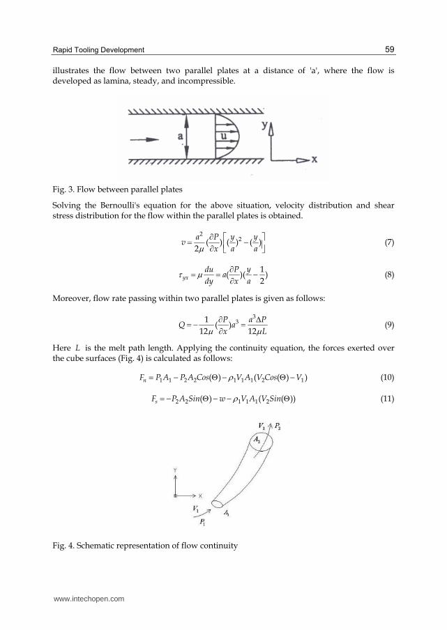
In the second case study, rapid wax injection mould tooling to be used for investment casting process is being developed. Investment casting process is considered as an economic approach in mass production of metal parts with complex shapes using different material alloys. In order to produce wax models for investment casting process, usually conventional tools manufactured via machining process are being used. On the other hand, using conventional tooling for wax model production may lead to extra time and cost, resulting in reduction of overall throughput and reducing the benefit of using such approach particularly for batch production. Rapid prototyping technology and its downstream applications in rapid tooling can lead to significant reduction in time and cost of design and production (Rosochowski & Matuszak, 2000). One of such applications is direct or indirect production of wax models needed in investment casting industry (Bonilla et al., 2001).
Fig. 12. Shift fork of Peugeot engine gearbox
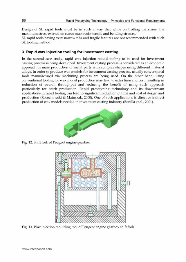
Fig. 13. Wax injection moulding tool of Peugeot engine gearbox shift fork
www.intechopen.com

Rapid Tooling Development
67
Applications in wax models demand a kind of processes which are able to produce the final shape and geometry of the part's critical features in near to the net shape with minimum post processing requirements. In this research stereolithography technique is used to fabricate the shell for tool master model of a shift fork of Peugeot engine gearbox (Fig. 12), then this shell is used to make the tool for producing wax model of shift fork via epoxy tooling and direct ACES injection moulding tooling method.
3.1 Methodology
In this research, first the 3-D model of the part was created in Catia software. Then, the CAD model of the shift fork was analyzed using MoldFlow to investigate the ideal and optimum conditions of tool operation during wax injection moulding process. In order to construct wax injection moulding tool, epoxy insert shells were fabricated directly from CAD data on an SL machine. These inserts were then fitted into steel mould bases through steel frames accompanied by cooling pipes and were back-filled with aluminum powder/aluminum chip/epoxy resin mixture (Fig. 13). The back-filled mixture added strength to the inserts and allowed heat to be conducted away from the mould.
Fig. 14. Tool assembly components and the steel frames
www.intechopen.com

Rapid Prototyping Technology – Principles and Functional Requirements
68
The modular steel mould bases were two standard base plates machined with a pocket to fit the steel frames and the inserts (Fig. 14) (Menges & Mohren, 1986). Next, vacuum casting machine (MCP 006) was used for creating wax patterns. Experiments were focused on optimization of casting parameters such as wax temperature, vacuum pressure, and mould temperature to achieve better dimensional accuracy of the wax models.
3.1.1 Design of wax model
The first step was creating the specific shape of the product. Therefore, the 3-D model of the part, based on the nominal dimensions, was created in Catia software (Fig. 15). The ideal dimensions are the nominal dimensions plus the shrinkage factors due to the wax material and final casting metal. Therefore, the actual dimensions of the model are the dimensions of the actual casting wax.
Fig. 15. Wax model parameters
3.1.2 Determination of shrinkage
In traditional moulding, the shrinkages of casting metal and wax material must be considered while creating the mould cavity (Siegfried & Wadenius, 2000). Thus, the mould cavity dimensions should be bigger than the nominal data to compensate the shrinkages of wax and casting metal. The wax shrinkage depends on the thermal conductivity of the mould and the wax solidification rate. Linear shrinkage of the wax could be estimated as follows:
100W FL
W
L LS
L
(12)
where SL is the linear shrinkage, LW is the tool dimension, and LF is the wax model dimension. However, if ┙ is defined as tool expansion coefficient and ┚ as wax expansion coefficient, C can be defined as the tool actual dimension as follows:
LF=LW(1+┙),C=LF(1+┚) C=LW(1+┙)(1+┚) (13)
www.intechopen.com
Rapid Tooling Development
69
However, in this research the shrinkage of casting metal was determined from casting design handbook and POULADIR Investment Casting Company (Investment Casting, 1968).
3.2 Tool simulation and analysis
Computer CAE simulation can reveal tool/model design problems, injection parameters, and difficulties encountered during operation, well before commencing the real operation. In this research, all tool design stages are simulated repeatedly to achieve optimum wax tool performance.
3.2.1 Wax injection process simulation
MoldFlow package was applied to simulate and predict different scenarios and investigate the optimum tool design and injection parameters according to the MoldFlow User Manual. Parameters investigated include filling patterns, temperature profiles, residual stresses, tool clamping force centre of gravity, the pressure at different time intervals, tool temperature at any time, and freeze time. Providing correct data input results in appropriate analysis. While providing wax model and tool data to the MoldFlow, the proposed wax data did not exist at the MoldFlow database. Therefore, by consulting MoldFlow Company, a similar wax data from Argueso Company was provided to the MoldFlow database. Among injection setting parameters, injection time was set at 10 s and freeze time at 30 s. Running different simulations resulted in the most favourable setting appropriate to produce 100 wax models per hour, whereas in conventional tooling these two parameters are 5 s and 10 s, which results in 300 shots per hour. Regarding tool surface temperature determination in MoldFlow, thermal analysis of ANSYS at permanent phase and MoldFlow at the transient phase was conducted according to the ANSYS User Manual, Version 6.1.
3.2.2 Simulation results analysis
Problems encountered during actual wax injection process such as weld lines and blush, are determined and corrected by the proper mould design, gate location, and gate design. Fig. 16 indicates air trap spots locations which may occur during wax injection. Fig. 17 indicates weld lines on the wax model where by choosing appropriate gate location, it avoids any weld lines. Filling process is clearly a complicated process. Fig. 18 indicates the mould filling time of 10.21 s and Fig. 19 indicates the complete melt temperature after the cavity being completely filled to analyze the consistency of uniform temperature distribution of the wax model. Fig. 20 indicates that the freeze time needed for the wax model is 30 s. The injection pressure of the mould cavity is 0.5 MPa.
3.3 Wax tool fabrication
For fabrication of the insert cavity using stereolithography machine, the 3-D CAD model from Catia software was corrected by applying the shrinkage values of wax and metal casting to the nominal dimensions. Then, the final CAD wax model was converted into STL format by 3-D Lightyear software. STL is a standard format in RP industries which approximates 3-D-model surfaces with several triangle facets. After implementation of some complementary actions on the STL model, like model review, defining supports, and build orientation, the final CAD file was sent to rapid prototyping apparatus. In this project, insert
www.intechopen.com

Rapid Prototyping Technology – Principles and Functional Requirements
70
Fig. 16. Air trap spots locations
Fig. 17. Wax model weld lines
www.intechopen.com

Rapid Tooling Development
71
Fig. 18. Wax model filling time
Fig. 19. Wax model temperature distribution
www.intechopen.com

Rapid Prototyping Technology – Principles and Functional Requirements
72
Fig. 20. Wax model freeze time
cavity was fabricated by photo-curable WaterShed 11120 resin with a 3-D SLA-5000™ machine (Fig. 21). Part layer thickness used in this process was 0.1 mm. After producing SLA inserts, post-processing operations such as washing excessive resin and removing supports were carried out, and finally core and cavity inserts were post cured in a UV oven. The final stage of post-processing operation was delicately finishing the inserts using a very fine sand paper.
Fig. 21. Fabricated inserts of Peugeot engine gearbox shift fork using stereolithography
www.intechopen.com
Rapid Tooling Development
73
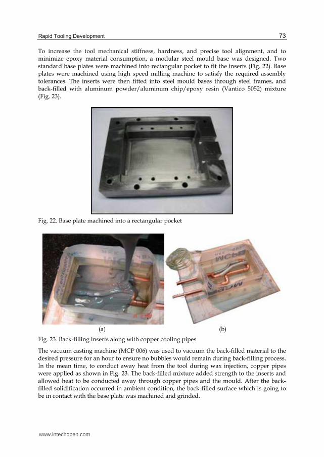
To increase the tool mechanical stiffness, hardness, and precise tool alignment, and to minimize epoxy material consumption, a modular steel mould base was designed. Two standard base plates were machined into rectangular pocket to fit the inserts (Fig. 22). Base plates were machined using high speed milling machine to satisfy the required assembly tolerances. The inserts were then fitted into steel mould bases through steel frames, and back-filled with aluminum powder/aluminum chip/epoxy resin (Vantico 5052) mixture (Fig. 23).
Fig. 22. Base plate machined into a rectangular pocket
(a) (b)
Fig. 23. Back-filling inserts along with copper cooling pipes
The vacuum casting machine (MCP 006) was used to vacuum the back-filled material to the desired pressure for an hour to ensure no bubbles would remain during back-filling process. In the mean time, to conduct away heat from the tool during wax injection, copper pipes were applied as shown in Fig. 23. The back-filled mixture added strength to the inserts and allowed heat to be conducted away through copper pipes and the mould. After the back-filled solidification occurred in ambient condition, the back-filled surface which is going to be in contact with the base plate was machined and grinded.
www.intechopen.com

Rapid Prototyping Technology – Principles and Functional Requirements
74
Fig. 24. Wax moulding of Peugeot engine gearbox shift fork
3.4 Wax tool injection process
During the initial moulding process, the wax injection test was carried out at SAPCO Co. manually, in such a way that two mould halves were held against each other using different holders and clamps. Then five shots of wax were injected at 80°C and at two bars pressure. Next, for the actual moulding process, the tool was taken to the POLADIR Investment Casting Company to produce final wax patterns. MV30 wax injection machine was used at vertical orientation and parameter settings were applied using the simulation analysis results. During the moulding process, the temperature and pressure of the cavity was monitored, and the melt temperature was controlled using different thermocouples to ensure that the conditions within the cavity remains as consistent as possible. Finally, 100 shots of shift fork of Peugeot engine gearbox were made with wax melt temperature at 65°C and 5 bars pressure (Fig. 24).
www.intechopen.com

Rapid Tooling Development
75
3.5 Discussion
The rapid wax injection tool was successfully tested and the results revealed the success of the technique. Slim edges and sharp corners have been very well reflected on the wax model. This is specially highlighted when compared with traditional tooling which requires special attention while machining sharp corners. For example, during machining the traditional tools, the tool radius leads to undesirable fillets, which requires additional process such as EDM machining to trim such fillets into sharp corners. Any additional process means additional time and cost, probably sacrificing accuracy as well. During wax model production, in spite of the abrupt difference in heat conductivity coefficient between epoxy and steel tool, heat of wax melt was conducted well to the tool base and the cycle time had no significant change compared with traditional tooling. Temperature data regarding barrel and nozzle during injection process is given in Table 5. The proper tool design, with copper cooling pipes and continuous tool temperature monitoring using different thermocouples, has resulted in uniform cycle profiles as shown in Fig. 25. According to the present production rate, the tool has produced 100 shots in an hour versus 300 shots in an hour in traditional tooling, which seems to be acceptable. It is possible to improve this rate using multi-cavity tool, which makes this technique further suitable and economical for fast part production.
Nozzle Barrel Upper plate Lower plate Wax model
65 60 13 14 45
Table 5. Temperature settings during wax injection process (°C)
Fig. 25. Temperature changes at tool cavity surface versus time in consecutive cycles
In order to check the dimensional accuracy of the wax model, optical measuring system was applied to extract the interested dimensions. The standard deviation of the wax model was 0.08 mm (Fig. 15). The general tolerance of the wax model was found to be in the range of ±0.1 mm, which was acceptable by the manufacturer. The nominal dimensions of the wax model are given at Table 6, and the actual dimensions of the produced wax model are given at Table 7.
www.intechopen.com

Rapid Prototyping Technology – Principles and Functional Requirements
76
L1 L2 L3 L4 L5 L6
77.8 62.42 15.38 11.99 11.33 45.1
L7 L8 L9 L10 L11 D1
32.7 21.12 9.74 8.2 15.38 19.47
Table 6. Wax model nominal dimensions (mm)
L1 L2 L3 L4 L5 L6
77.5 62.1 15.17 11.8 11.25 45.3
L7 L8 L9 L10 L11 D1
32.53 20.82 9.55 8.15 15.1 19.25
Table 7. Wax model actual dimensions (mm)
Comparing the results of Table 6 and Table 7, the largest difference belongs to L1 and L3, which is 0.3 mm. These two parameters are located where they can have free shrinkage while other parameters have constraint in shrinkage. With respect to the thickness, except L4 which has 0.19 mm increase in thickness, the remaining parameters fit within the tolerance. Parameter L11 has shrinkage of 0.29 mm which is precisely equivalent to the forecasted value suggested by the simulation software (Fig. 26).
Fig. 26. Wax model warpage and shrinkage after ejection
Considering the difference between the nominal and actual dimensions, and with respect to the applied coefficient of shrinkage, it could be concluded that the tool cooling method has influence on the wax shrinkage (Modukuru et al., 1996). Moreover, those parameters which
www.intechopen.com
Rapid Tooling Development
77
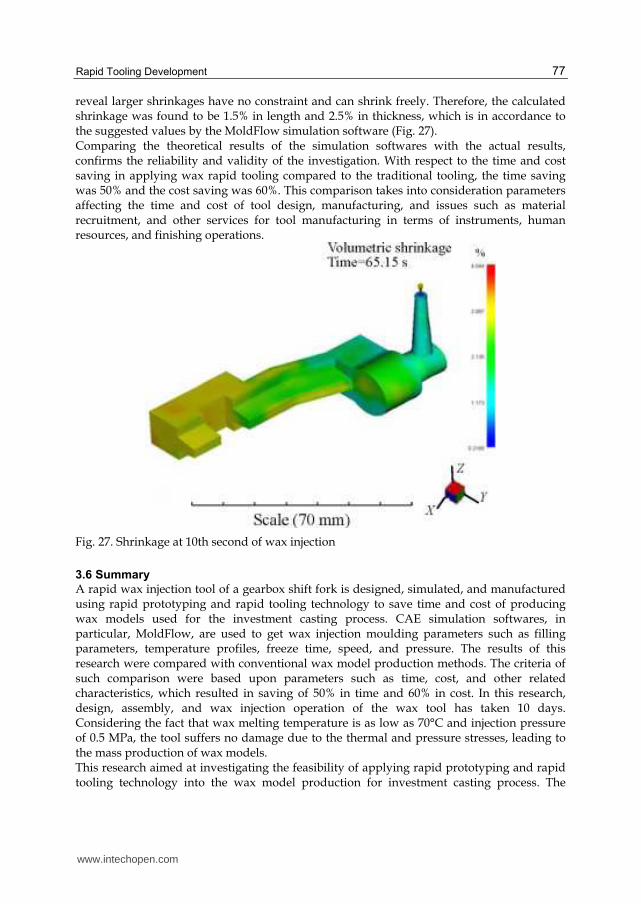
reveal larger shrinkages have no constraint and can shrink freely. Therefore, the calculated shrinkage was found to be 1.5% in length and 2.5% in thickness, which is in accordance to the suggested values by the MoldFlow simulation software (Fig. 27). Comparing the theoretical results of the simulation softwares with the actual results, confirms the reliability and validity of the investigation. With respect to the time and cost saving in applying wax rapid tooling compared to the traditional tooling, the time saving was 50% and the cost saving was 60%. This comparison takes into consideration parameters affecting the time and cost of tool design, manufacturing, and issues such as material recruitment, and other services for tool manufacturing in terms of instruments, human resources, and finishing operations.
Fig. 27. Shrinkage at 10th second of wax injection
3.6 Summary
A rapid wax injection tool of a gearbox shift fork is designed, simulated, and manufactured using rapid prototyping and rapid tooling technology to save time and cost of producing wax models used for the investment casting process. CAE simulation softwares, in particular, MoldFlow, are used to get wax injection moulding parameters such as filling parameters, temperature profiles, freeze time, speed, and pressure. The results of this research were compared with conventional wax model production methods. The criteria of such comparison were based upon parameters such as time, cost, and other related characteristics, which resulted in saving of 50% in time and 60% in cost. In this research, design, assembly, and wax injection operation of the wax tool has taken 10 days. Considering the fact that wax melting temperature is as low as 70°C and injection pressure of 0.5 MPa, the tool suffers no damage due to the thermal and pressure stresses, leading to the mass production of wax models. This research aimed at investigating the feasibility of applying rapid prototyping and rapid tooling technology into the wax model production for investment casting process. The
www.intechopen.com
Rapid Prototyping Technology – Principles and Functional Requirements
78
results not only confirm the success of such application, but also prove valuable benefits with respect to the common tooling techniques.
Due to the fact that many moulding parameters inside the cavity such as pressure and melt temperature, are not easily possible to be measured; therefore, CAE simulation softwares are unique and inexpensive alternatives to analyze and evaluate such rapid tools.
Obviously, CAE simulation softwares such as MoldFlow and ANSYS are significant aids in rapid tooling analysis, acquiring tooling parameters and melt behavior in the cavity; and today's rapid tooling analyses of different tooling techniques have been developed and are complementary.
The results of this research indicate saving of 50% in time and 60% in cost. Design, assembly, and wax injection operation took 10 days, compared with the traditional techniques which may take at least two month.
Considering the fact that wax melting temperature is as low as 70°C and injection pressure of 0.5 MPa, the tool may suffer no damage due to the thermal and pressure stresses, leading to the mass production of wax models.
Using simulation softwares prevents common moulding defects well in advance before being encountered during operation.
Injection cycle time is found to be between 40–50 sec which is longer than the common tooling techniques (5–15 sec), which is due to the fact that the tool cavity is a nonconductive material; however, this may be improved by increasing the number of cavities (multi cavity).
Due to the modular nature of tool plate and frame assembly, it is possible to reuse the material for similar tool dimensions, leading to more saving in time and cost for new tools.
According to the above findings, it could be concluded that the rapid wax injection tooling is an appropriate alternative for mass production via investment casting process. Therefore, rapid wax injection tooling technique could replace many expensive, time consuming, and complex machining techniques.
4. Acknowledgment
The author would like to thank the Islamic Azad University – Majlesi Branch, Rapid Prototyping & Tooling Branch of SAPCO Part Supplier of Car Manufacturing Co. of Iran-Khodro and POULADIR Investment Casting Company for supporting this project.
5. References
Bibb, et al. (2009). Rapid manufacture of custom-fitting surgical guides, Rapid Prototyping
Journal, Vol. 15, No. 5, pp. 346–354, DOI: 10.1108/13552540910993879, ISSN 1355-
2546.
Bonilla, W.; Masood, SH. & Iovenitti, P. (2001). An investigation of wax patterns for
accuracy improvement in investment cast parts, The International Journal of Advanced
Manufacturing Technology, 18 (5), pp. 348–356, DOI: 10.1007/s001700170058, ISSN
0268-3768.
www.intechopen.com
Rapid Tooling Development
79
Campbell, et al. (2011). Additive manufacturing in South Africa: building on the
foundations, Rapid Prototyping Journal, Vol. 17, No. 2, pp. 156–162, DOI:
10.1108/13552541111113907, ISSN 1355-2546.
Chen, D. & Cheng, F. (2000). Integration of Product and Process Development Using Rapid
Prototyping and Work-Cell Simulation Technology, Journal of Industrial Technology,
Vol. 16, No. 1.
Decelles, P. & Barritt, M. (1996). Direct AIM Prototype Tooling, 3D Systems, P/N 70275/11-
25-96.
Evans, M.A. & Campbell, R. I. (2003). A Comparative evaluation of industrial design models
produced using Rapid Prototyping and workshop-based fabrication techniques.
Rapid Prototyping Journal, Vol. 9, No. 5, DOI: 10.1108/13552540310502248, ISSN
1355-2546.
Gargiulo, E.P. (1992). Stereolithography Process Accuracy; user experience. Proceedings of 1st
European conference on rapid prototyping, pp. 187-201.
Greaves, T. (1997). Case Study: Using Stereolithography to Directly Develop Rapid Injection
Mold Tooling, (Delphi-GM), TCT Conference.
Ilyas, et al. (2010). Design and manufacture of injection mould tool inserts, Rapid Prototyping
Journal, Vol. 16, No. 6, pp. 429-440, DOI: 10.1108/13552541011083353, ISSN 1355-
2546.
Investment Casting Institute. (1968). Investment Casting Handbook. Chicago.
Jacobs, P.F. (1992). Rapid Prototyping and Manufacturing - Fundamentals of
Stereolithography, McGraw-Hill Inc, New York.
Jacobs, P.F. (1996). Recent Advances in Rapid Tooling from Stereolithography, A Rapid
Prototyping Conference, University of Maryland, USA.
Menges, G. & Mohren, P. (1986). How to Make Injection Molds, Hanser, Munich.
Modukuru, SC.; Ramakrishnan, N. & Sriramamurthy, AM. (1996). Determination of the die
profile for the investment casting of aerofoil-shaped turbine blades using the finite-
element, Journal of Materials Processing Technology, 58 (2-3), pp. 223–226,
DOI:10.1016/0924-0136(95)02127-2.
Rahmati, S. & Dickens, P.M. (1997). Stereolithography for Injection Mould tooling. Rapid
Prototyping Journal, Vol. 3, No. 2, pp. 53-60, DOI: 10.1108/13552549710176671, ISSN
1355-2546.
Rahmati, S., and Dickens, P. M., (2005) Stereolithography Rapid tooling for Injection
Moulding, 2nd International Conference on Advanced Research in Virtual and
Rapid Prototyping, Leiria, Portugal, Edited by Dr P.J. Bártolo et al., Taylor &
Francis, ISBN 0-415-39062-1.
Rauwendaal, Chris. (2000). Statistical Process Control in Injection Molding and Extrusion,
Hanser, Munich, ISBN 3-446-18814-2.
Richard, P. C. (1993). Material and Process Parameters that Affect Accuracy in
Stereolithography, Solid freeform fabrication proceedings, pp. 245-252.
Rosochowski, A. & Matuszak, A. (2000). Rapid tooling: The state of art, Journal of Materials
Processing Technology, 106, pp. 191–198, DOI:10.1016/S0924-0136(00)00613-0.
www.intechopen.com

Rapid Prototyping Technology – Principles and Functional Requirements
80
Quail, et al. (2010). Development of a regenerative pump impeller using rapid
manufacturing techniques, Rapid Prototyping Journal , Vol. 16, No. 5, pp. 337–344,
DOI: 10.1108/13552541011065731, ISSN 1355-2546.
Siegfried, W. & Wadenius, B. (2000). The expansion/shrinkage behaviour of wax. Report
from J. F. Mccaughin Co.
Walter, M. & Helmut, G. (2000). Training in Injection, Molding, , Hanser, Munich, ISBN 10:
1-56990-302-6
Weiss, et al. (1990). A Rapid Tool Manufacturing System Based on Stereolithography and
Thermal Spraying, ASME Manufacturing Review, Vol. 3, pp. 40-48.
www.intechopen.com

Rapid Prototyping Technology - Principles and FunctionalRequirementsEdited by Dr. M. Hoque
ISBN 978-953-307-970-7Hard cover, 392 pagesPublisher InTechPublished online 26, September, 2011Published in print edition September, 2011
InTech EuropeUniversity Campus STeP Ri Slavka Krautzeka 83/A 51000 Rijeka, Croatia Phone: +385 (51) 770 447 Fax: +385 (51) 686 166www.intechopen.com
InTech ChinaUnit 405, Office Block, Hotel Equatorial Shanghai No.65, Yan An Road (West), Shanghai, 200040, China
Phone: +86-21-62489820 Fax: +86-21-62489821
Modern engineering often deals with customized design that requires easy, low-cost and rapid fabrication.Rapid prototyping (RP) is a popular technology that enables quick and easy fabrication of customizedforms/objects directly from computer aided design (CAD) model. The needs for quick product development,decreased time to market, and highly customized and low quantity parts are driving the demand for RPtechnology. Today, RP technology also known as solid freeform fabrication (SFF) or desktop manufacturing(DM) or layer manufacturing (LM) is regarded as an efficient tool to bring the product concept into the productrealization rapidly. Though all the RP technologies are additive they are still different from each other in theway of building layers and/or nature of building materials. This book delivers up-to-date information about RPtechnology focusing on the overview of the principles, functional requirements, design constraints etc. ofspecific technology.
How to referenceIn order to correctly reference this scholarly work, feel free to copy and paste the following:
Sadegh Rahmati (2011). Rapid Tooling Development, Rapid Prototyping Technology - Principles andFunctional Requirements, Dr. M. Hoque (Ed.), ISBN: 978-953-307-970-7, InTech, Available from:http://www.intechopen.com/books/rapid-prototyping-technology-principles-and-functional-requirements/rapid-tooling-development

© 2011 The Author(s). Licensee IntechOpen. This chapter is distributedunder the terms of the Creative Commons Attribution-NonCommercial-ShareAlike-3.0 License, which permits use, distribution and reproduction fornon-commercial purposes, provided the original is properly cited andderivative works building on this content are distributed under the samelicense.