rapid pcb - cuhk electronic engineering programmeymfung/lpkf.pdf · 1.introduction circuitcam 4.0...
TRANSCRIPT

Rapid Rapid PCBPCBPrototyping Prototyping
Laboratory TutorialLaboratory TutorialM60

1.Introduction1.Introduction
CircuitCAMCircuitCAM 4.04.0Is a combined computer aided design and computer aided Is a combined computer aided design and computer aided manufacturing.manufacturing.import, check and edit circuit board production data (Gerber import, check and edit circuit board production data (Gerber data) then output a CAM format (LMD file) for M60.data) then output a CAM format (LMD file) for M60.
BoardMasterBoardMaster 4.04.0Is a program for the automatic control LPKFIs a program for the automatic control LPKF--M60 circuit M60 circuit board plotter.board plotter.

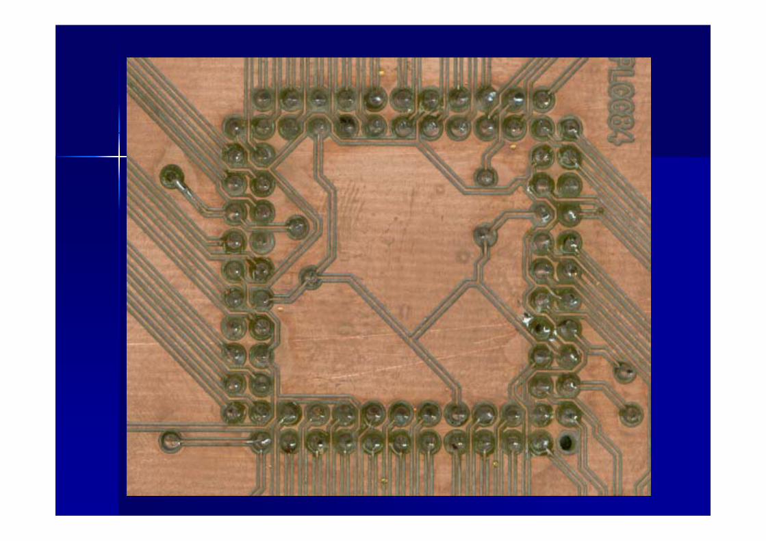
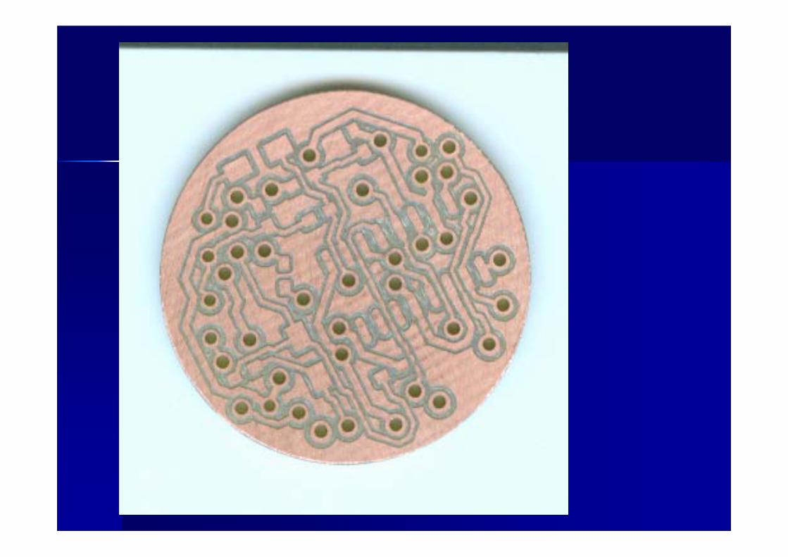
Drill
Contour
RuboutIsolate


1. Gerber data(machine-readable files that describe the layers on PCB)-Aperture list-Tool list
2. Excellon data(Describe the drills size and position)

Gerber data

Isotation Milling Tool36mm long
CuFR4
Contour Milling Tool38mm long

Drilling Tool38mm long

Changing Tool
1.Turn right or left until it hold2.Push Down3.Counter-Clockwise to release tool4.Clockwise to tie tool5.Pull up.
2
5

2. Prepare CAM format in 2. Prepare CAM format in PowerPCBPowerPCB 5.05.0

Board Outline
Example : 2 layers
Origin
Top layer
Bottom layer
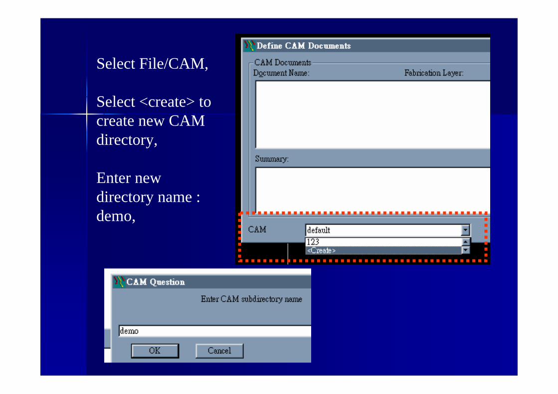
Select File/CAM,
Select <create> to create new CAM directory,
Enter new directory name :demo,
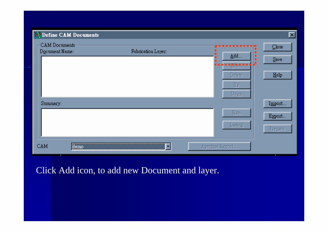
Click Add icon, to add new Document and layer.

Type name in Document Name, “demotop”
Select Document Type “Routing”.

Select “Top”layer.
The output file is art001.pho

Click the layers icon, and check “Board Outline” box in other field.

Click “Preview Selections” icon,To preview top layer.
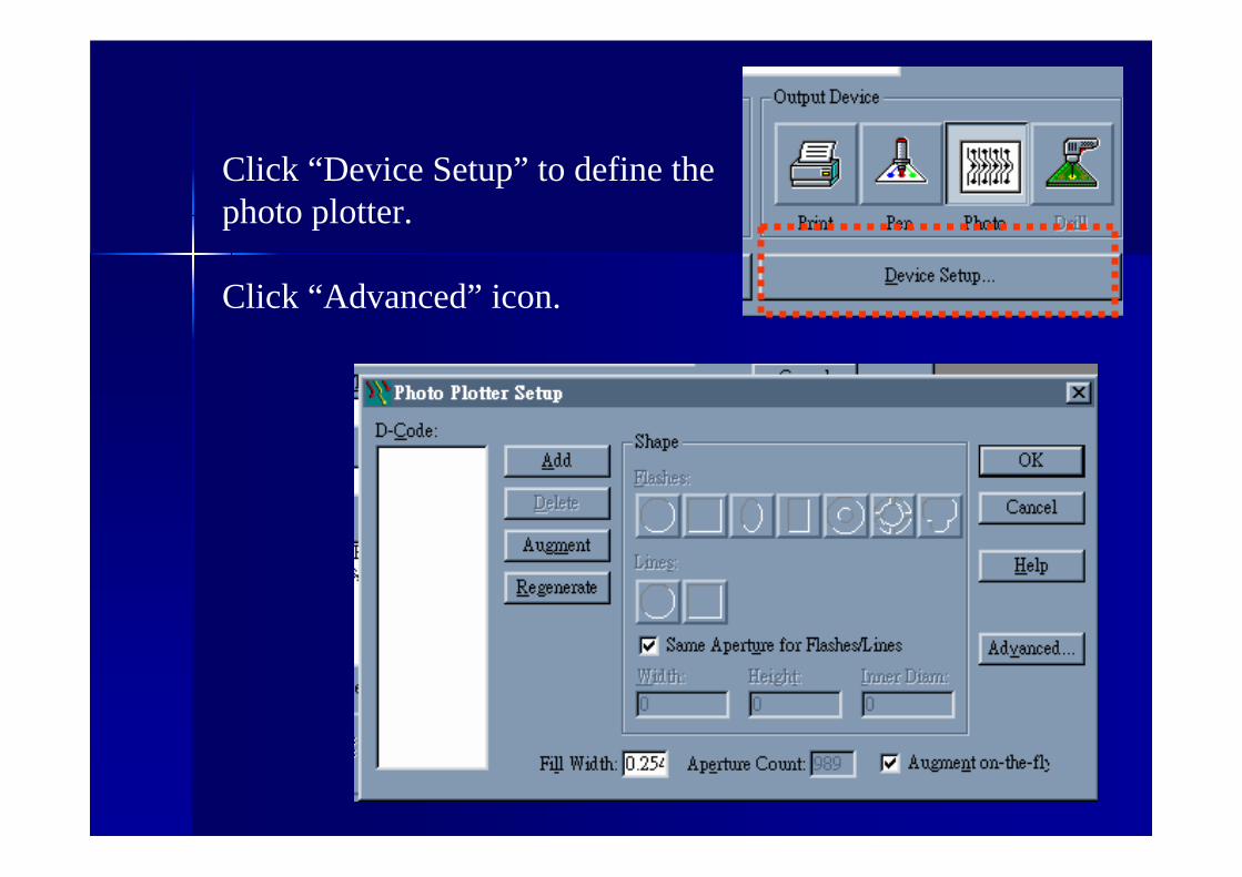
Click “Device Setup” to define the photo plotter.
Click “Advanced” icon.

Set units, number of digits, coordinates, zero suppress and output format as below. Output Format is RS-274X format.

Click “Add” icon in photo plotter setup, and enter 10 in Aperture number.

Select Circle Flashes and enter width “0.02”

Click “Augment” icon, to automatically add aperture table.

D-Code will generate for your design.

Click Add icon, to add another document bottom layer.Select Routing in document type.Select Bottom layer in Layer Association windows.Output file is art002.pho for bottom layer.

Click Add to add NC_drill file for drill pattern.

Select NC_Drillformat in Document Type.
The output file is drl001.drl
Document Name is demodrill

Click device setup to view NC Drill file setting.
Addition Note: Here is toollist for CircuitCAM : PowerPCBx x Exc mm Inch23AbsLead.txt (NCDrill)

Now three layer is added.Top layer, bottom layer and drill file

Select three file, and click “Run” icon to generate CAM file.

Click “Y” to generate output file.
Also, Click “Aperture Report” icon, to generate aperture report file.
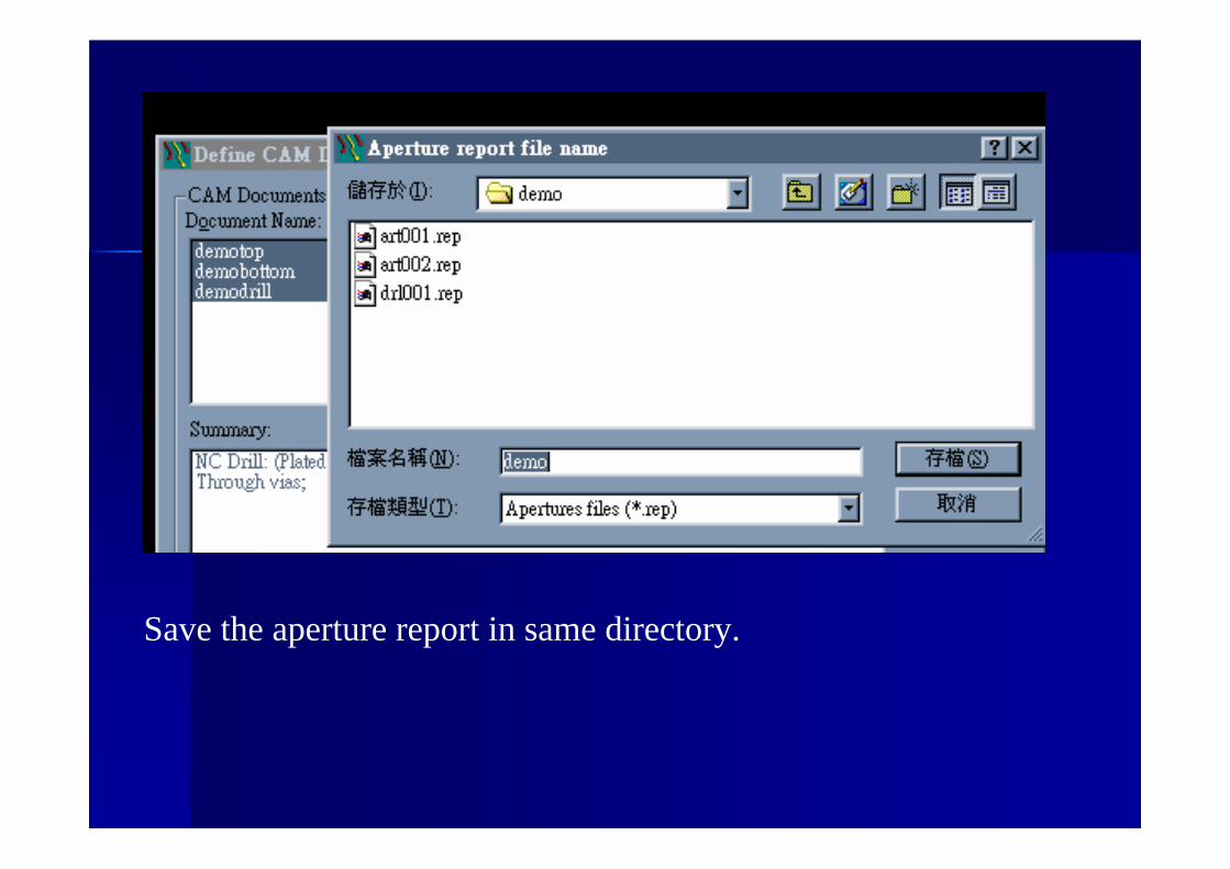
Save the aperture report in same directory.

Notepad will open aperture report automatically.
3. Import CAM format3. Import CAM formattotoCircuitCAMCircuitCAM 4.04.0

Open CircuitCAM 4.0

In Wizard Mode,
Click Graphic Mode to change to Graphic mode from Wizard Mode.

Here is Graphic Mode.

Select File/New/DoubleSided.catto select double layer design template.
Click “import” icon or select File/import to import top layer .
Art001.pho is gerber file of top layer.
Import art001.pho as top layer.

Select GerberX format in file-type field,
Select toplayer in layer field,
Ignore aperture list.

Make sure size x,y is correct, or click preview to measure the size of your design.
Otherwise change the values, unit, decimal position, digits m.n in order to correct the x,y size.

After import gerber file of top layer art001.pho.

Select File/Import to import bottom layer of art002.pho.
Select Bottomlayerin layer field.

After import top and bottom layer,In Default setting, Red is top layer, green is bottom layer.

Select File/import, import drl001.rep to define the drill tool list.
Select Apertures/Tools select in File-Type field.
Select PowerPCBx x Exc mm Inch23AbsLead.txt (NCDrill) in Aperture/Tool Template field.

Diameter is about 0.9mm ~ 3mm

Select File/import, import drl001.drl to define drill position.
Select DrillPlated in Layer field.
Wrong Size x,yToo large…,
Change the option and digits m.n.

Click Trailing zeros present to correct the size x,y,Click “Preview” icon to preview.

Click “import” icon to import drillplated layer.

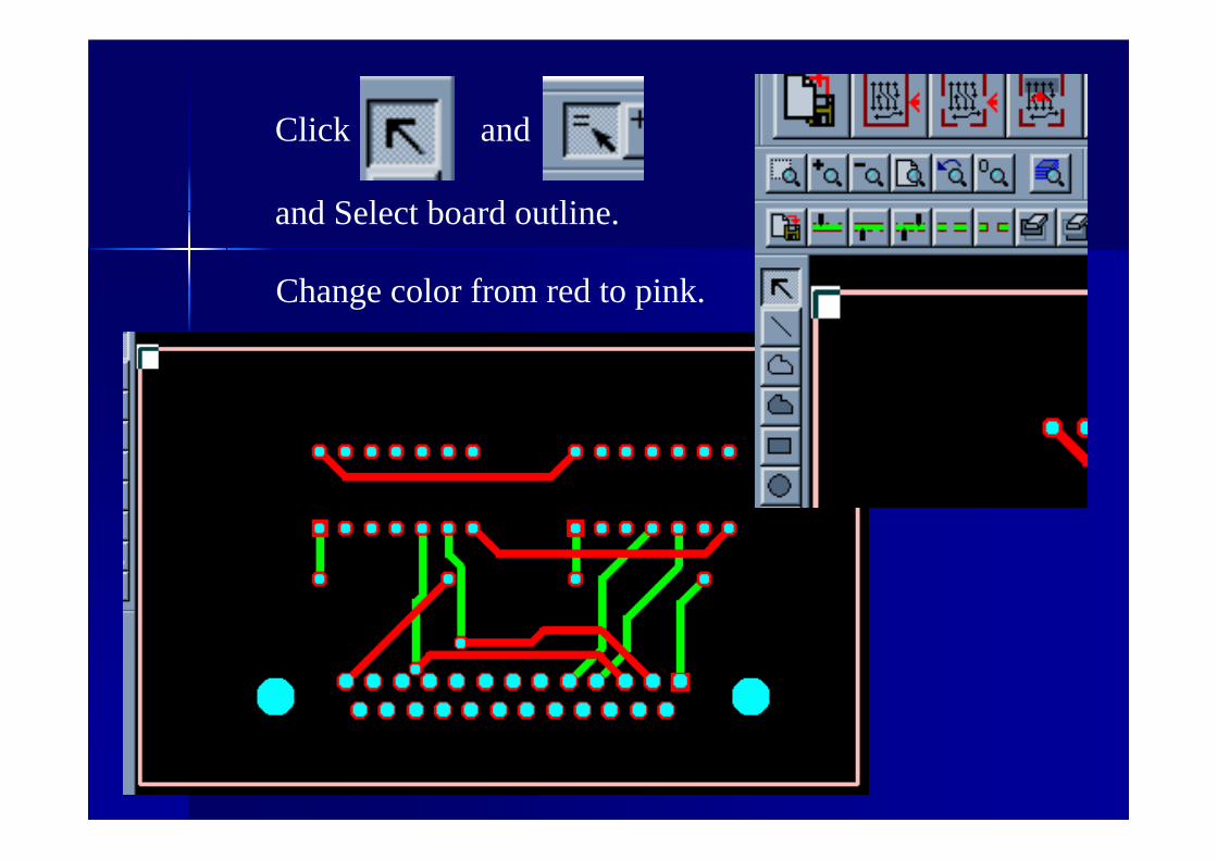
Click and
and Select board outline.
Change color from red to pink.

Click “contour routing” icon to create contour.
Click “Run” icon to create contour.

Grey color of contour is created.Press delete key to delete the selected board outline.
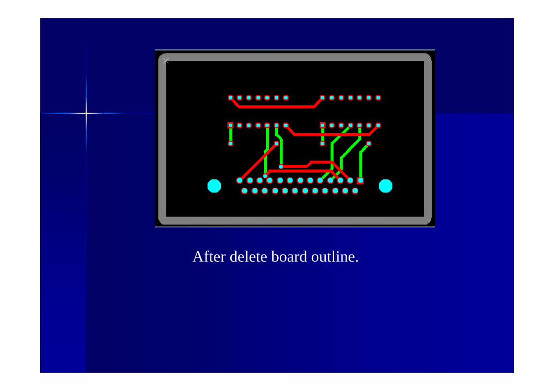
After delete board outline.
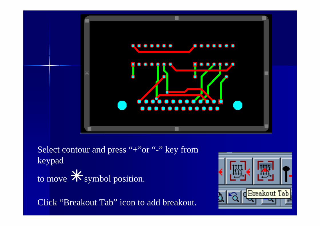
Select contour and press “+”or “-” key from keypad
to move symbol position.
Click “Breakout Tab” icon to add breakout.

After add two breakout.

Click “insulate all layer” icon to create insulate.

After insulate.

insulate

Define the width of insulate,Base 0.2mm, Special 0.3mmClick Run icon.


Click “Export LpkfCircuitBoard Plotter” icon to export LMD file for boardmaster4.0.

Click “Layers” icon to show used layers.


4. Import LMD format4. Import LMD formattotoBoardMasterBoardMaster 4.04.0
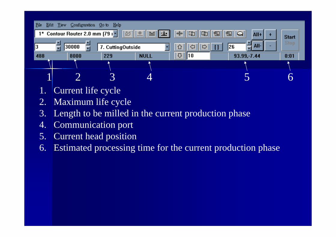
1. Current life cycle2. Maximum life cycle3. Length to be milled in the current production phase4. Communication port5. Current head position6. Estimated processing time for the current production phase
1 2 3 4 5 6

1. Pause position3. Home position5. Exchange position
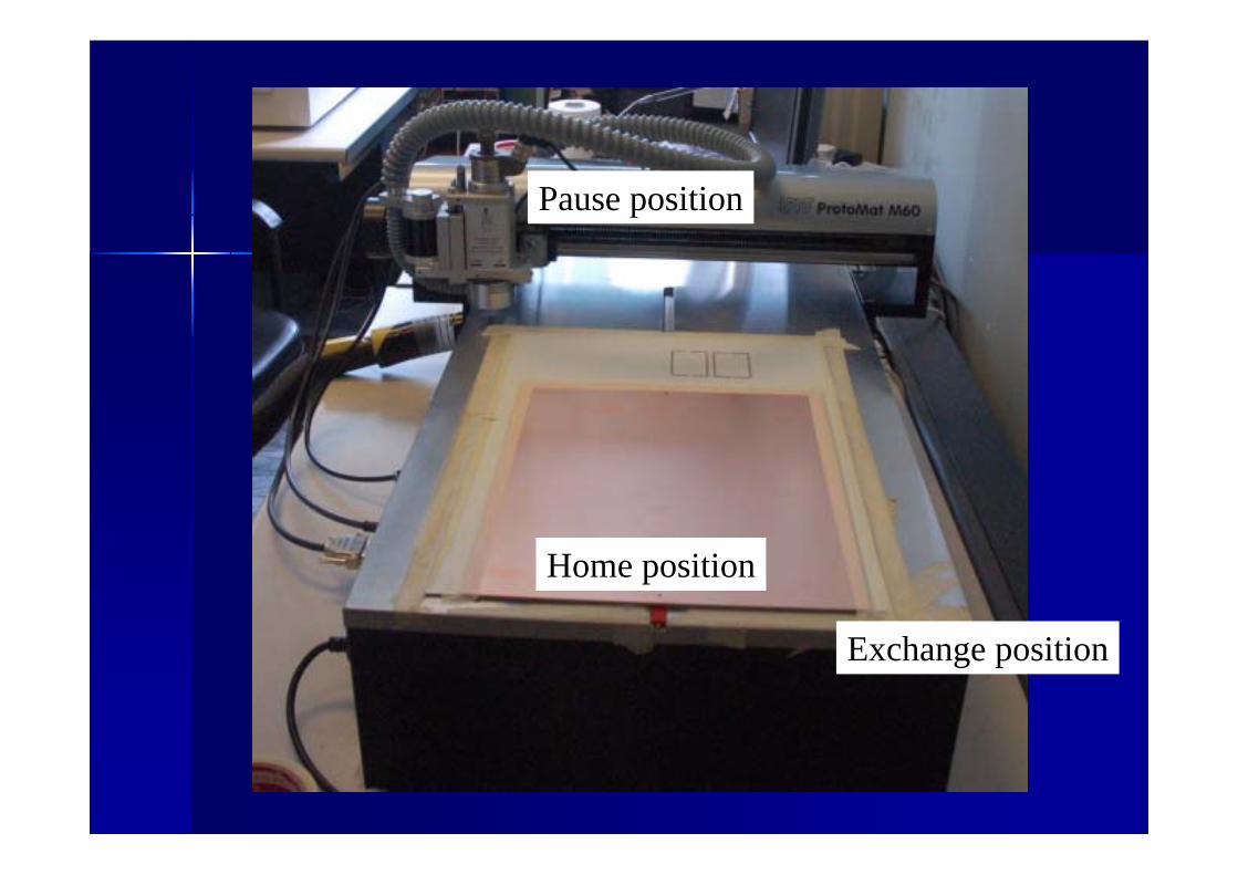
Pause position
Home position
Exchange position

For double side PCB fabrication,Drill 3.0mm is used to define the PCB positionThe distance between to hole is 287mm.
For single side, no need to drill hole.
Home
x
x

Select Configuration/Connect,Click “Channel” to connect PC and Plotter.

Click “BoardMaster4.0” icon to open BoardMaster4.0 program.
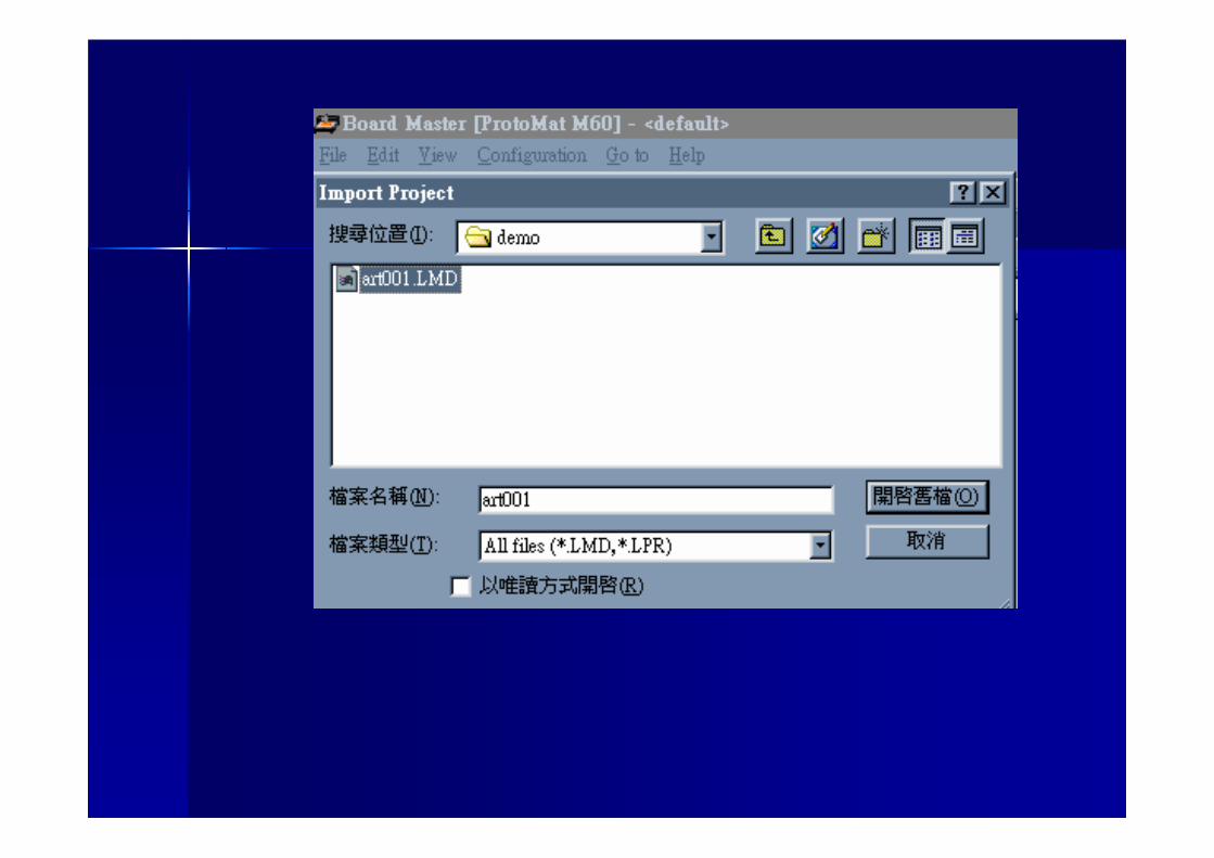
Select File/Import to import LMD file.

Select File/SAVE to save job
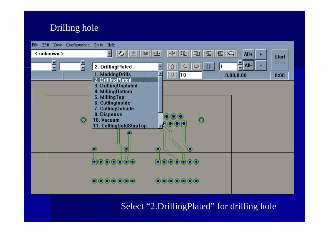
Select “2.DrillingPlated” for drilling hole
Drilling hole

Click Move icon to move the project

Click “All+”icon to select all drill.Change color from dark blue to light blue.
Click Start to start drilling process.
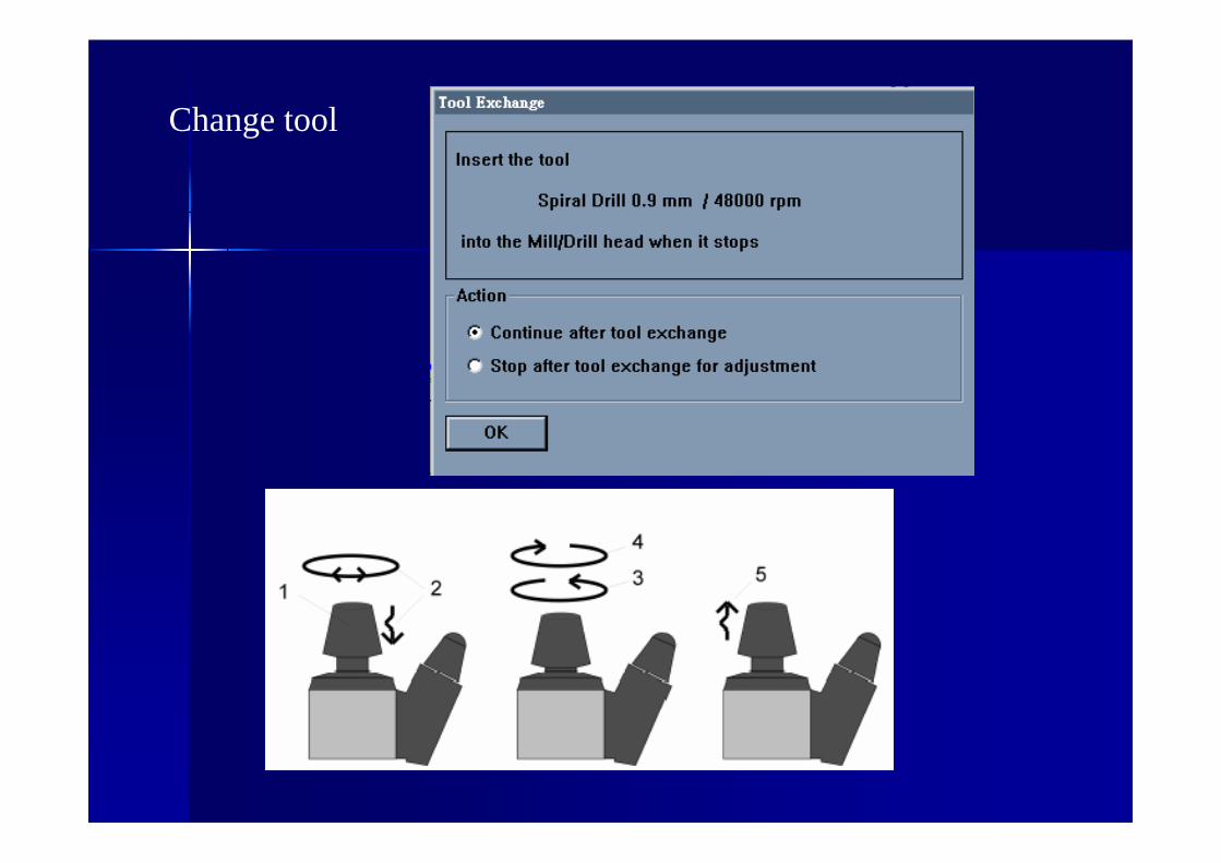
Change tool

Change tool

Change tool
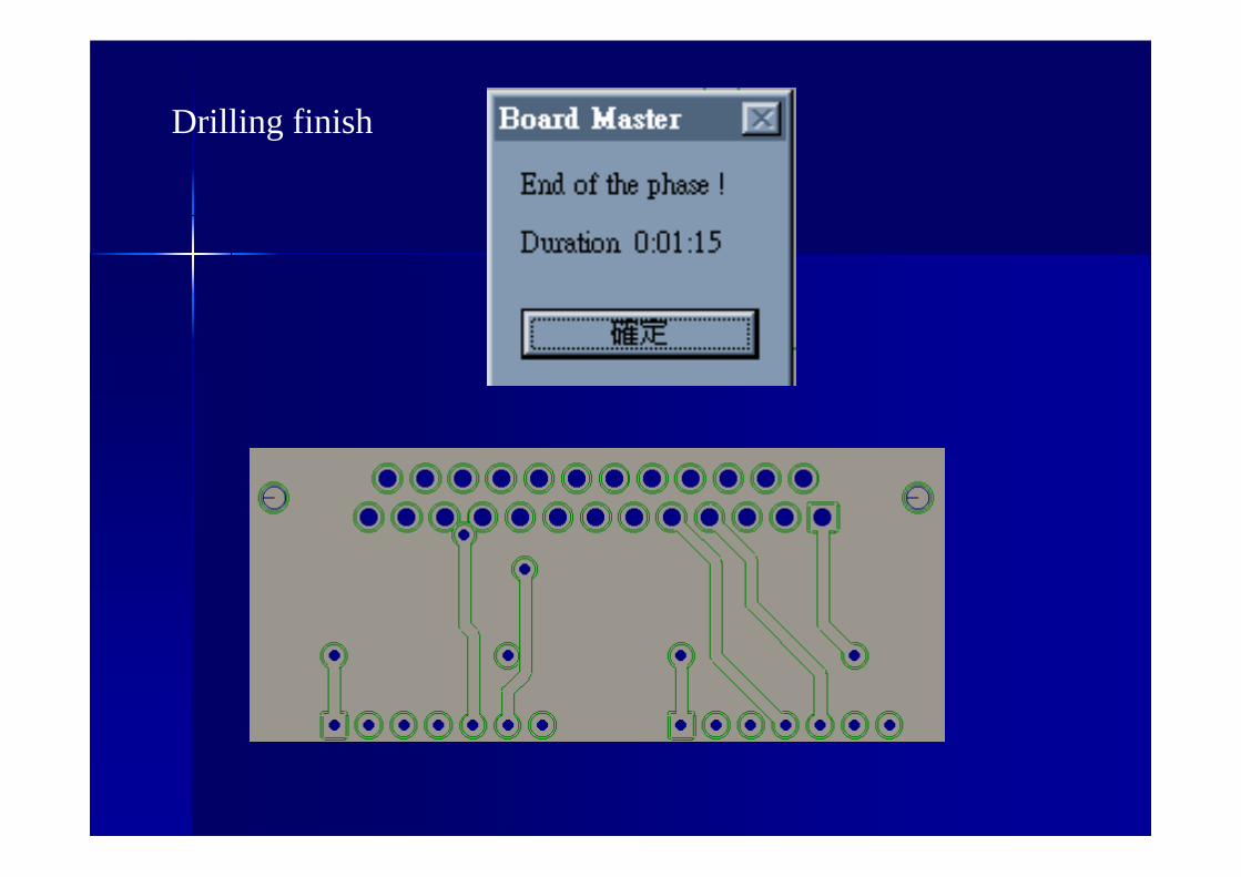
Drilling finish

Milling Bottom layer
Select “4.MillingBottom” to milling bottom layerClick “All+” icon to select all milling top.Click Start to start milling process.
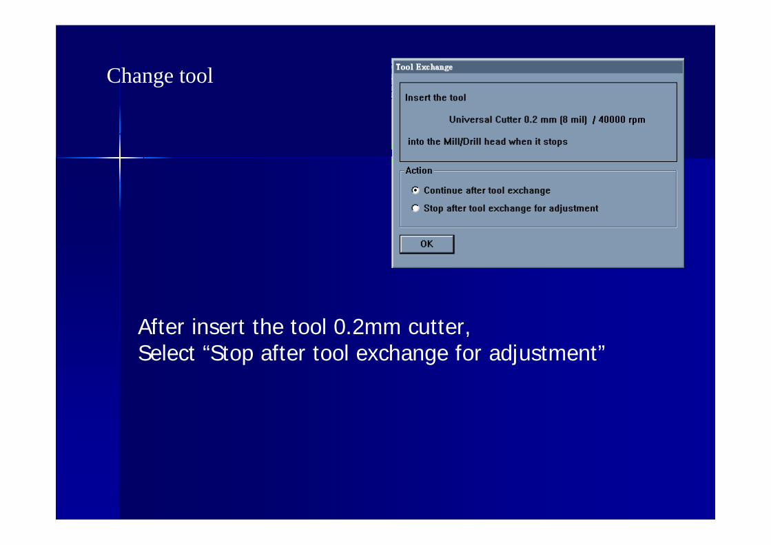
Change tool
After insert the tool 0.2mm cutter, Select “Stop after tool exchange for adjustment”

Click icon to move the header to free space of PCBfor adjustment.
Input 3 for header movement step in mm
Click icon motor on to turn on the motor
Click icon down the motor
and press the direction icon. After milling, click icon to up the motor

Inspection Microscopes for adjustment
After milling 3mm,
Use inspection microscopes to measure the milling width.
The milling width for universal cutter is 0.2mm
Click “Start” icon to mill if milling width is about 0.2mm in microscopes adjustment.

If the width is not exactly 0.2mm, turn the screw.
And repeat the adjustment process !!

During milling
Milled.

Select “4.MillingTop” to milling top layer
Milling top layer
Click “All+” icon to select all milling top.Click Start to start milling process.

During milling
Milled.

Milling contour
Select “7.CuttingOutside” to milling contour.
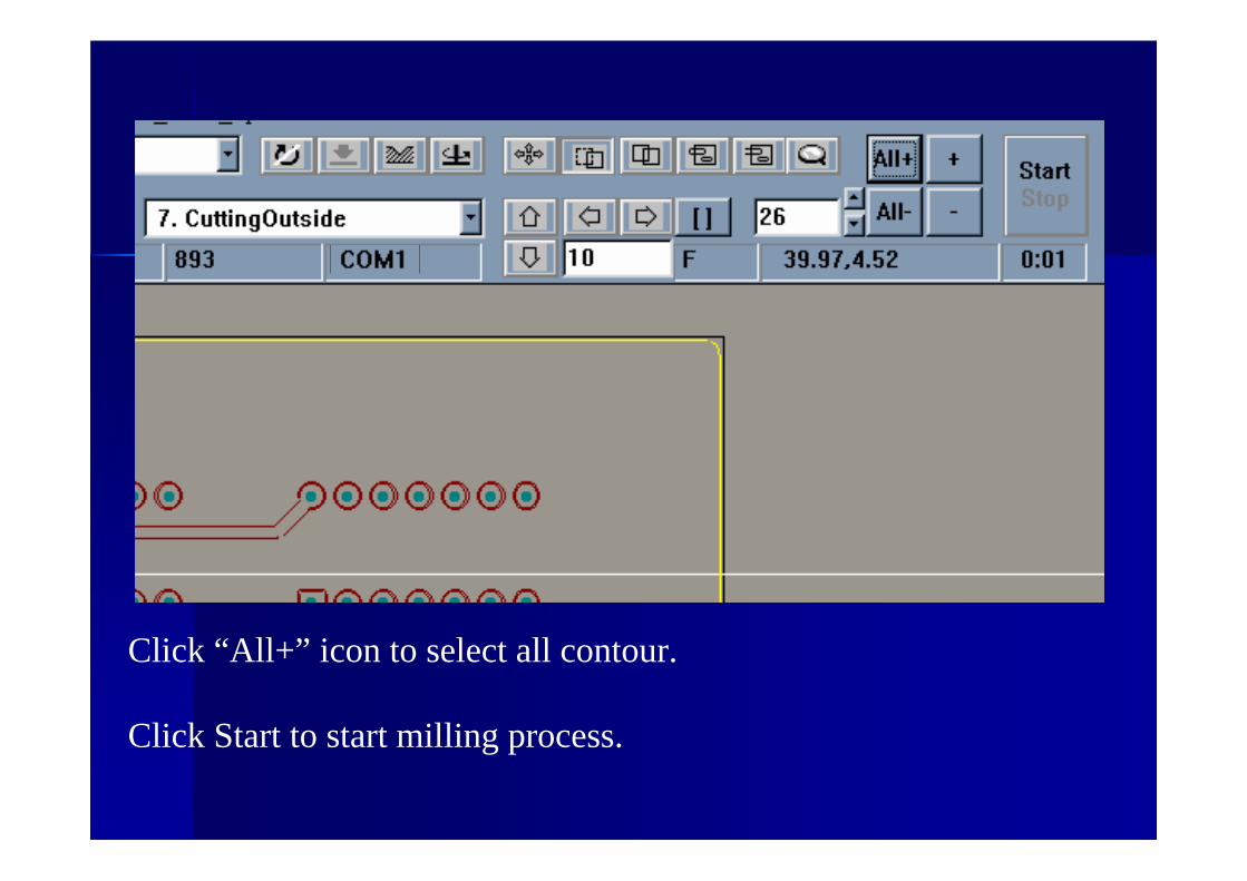
Click “All+” icon to select all contour.
Click Start to start milling process.

Change tool
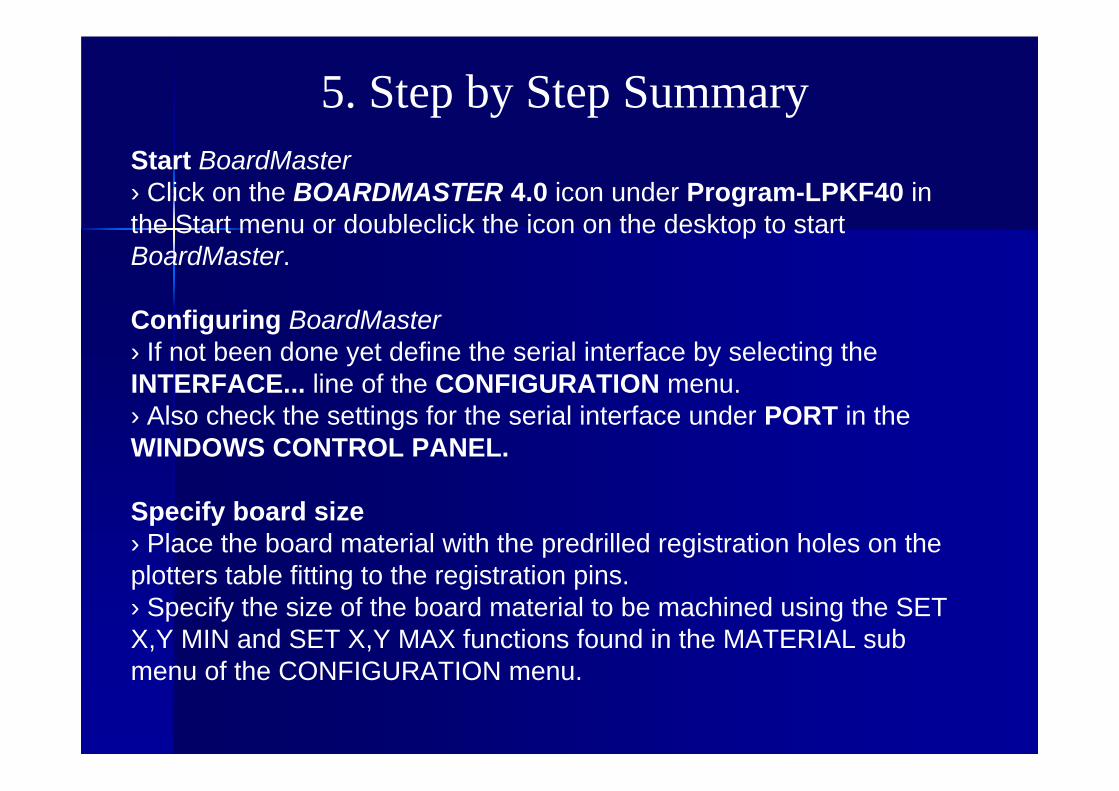
5. Step by Step Summary Start BoardMaster› Click on the BOARDMASTER 4.0 icon under Program-LPKF40 inthe Start menu or doubleclick the icon on the desktop to startBoardMaster.
Configuring BoardMaster› If not been done yet define the serial interface by selecting theINTERFACE... line of the CONFIGURATION menu.› Also check the settings for the serial interface under PORT in theWINDOWS CONTROL PANEL.
Specify board size› Place the board material with the predrilled registration holes on theplotters table fitting to the registration pins.› Specify the size of the board material to be machined using the SETX,Y MIN and SET X,Y MAX functions found in the MATERIAL submenu of the CONFIGURATION menu.

Open or create the job
› Open an existing job by selecting OPEN... line from the FILE menu
or create a new job by selecting the NEW line of the FILE menu.
Import production data
› Import LMD production data created by CircuitCAM or HP-GL project
files already created by BoardMaster by selecting the LMD OR
LPR... line from the IMPORT sub menu of the FILE menu.

Place production data
› Place the imported production data or projects by selecting the
PLACEMENT... line from the EDIT menu or using
the buttons in the tool bar.
Save job
› Save the job following placement of all projects by selecting the
SAVE AS line from the FILE menu.

Enable Automotor
› Enable the Automotor function by clicking on in the tool bar.
Disabled function is indicated by a white slash through the icon .
Select data
› Select the data to be sent to the circuit board plotter using the
selection buttons in the tool bar:
Start drilling/milling operation for the production phase selected
› Click on in the tool bar to send the selected data for the
current production phase to the circuit board plotter via the serial
interface.