rapid fabrication and characterization of mems...
TRANSCRIPT

IOP PUBLISHING JOURNAL OF MICROMECHANICS AND MICROENGINEERING
J. Micromech. Microeng. 22 (2012) 115031 (11pp) doi:10.1088/0960-1317/22/11/115031
Rapid fabrication and characterization ofMEMS Parylene C bellows for largedeflection applicationsH M Gensler1 and E Meng1,2
1 Department of Biomedical Engineering, Viterbi School of Engineering, University of SouthernCalifornia, 1042 Downey Way, DRB-140, Los Angeles, CA 90089-1111, USA2 Ming Hsieh Department of Electrical Engineering, University of Southern California, 3740 McClintockAvenue, EEB-100, Los Angeles, CA 90089-2560, USA
E-mail: [email protected]
Received 13 July 2012, in final form 27 August 2012Published 11 October 2012Online at stacks.iop.org/JMM/22/115031
AbstractWe present a rapid, high-yield fabrication process for Parylene C microbellows for largedeflection applications and their characterization. Bellows having different convolutionnumber, wall thickness, inner diameter and outer diameter and layer height were fabricatedusing a lost wax-like process. The effect of design parameters on overall bellows performancewas evaluated through load–deflection testing and finite element modeling (FEM) simulations.Large deflection (!mm) was achieved under relatively low applied pressure (!kPa). The onsetof bellows hysteresis (4.19 kPa or 0.60 psi) was determined in mechanical testing andapproximated by FEM. For the bellows tested, convolution number, wall thickness and outerdiameter had the greatest impact on load–deflection (axial extension) performance.Demonstration of bellows for fluid pumping was achieved through integration withelectrochemical actuators operated under low power (!3 mW). Combined with thebiocompatibility, chemical inertness and low permeability of Parylene C,microelectromechanical systems (MEMS) bellows have the potential to enable novelapplications in MEMS actuators and microfluidic systems.
(Some figures may appear in colour only in the online journal)
1. Introduction
A bellows is a thin-walled corrugated tube [1] typically usedas a pressure-responsive device (switch, gauge), flexible shaftcoupling, or as a hermetic housing [2]. Miniature metal andceramic bellows have been employed extensively in manyapplications, but often require large driving pressures (>MPa)to produce only modest deflections (tens of microns) dueto the relatively high Young’s modulus of the materials[3]. A polymer bellows typically has a Young’s modulusorders of magnitude less than those of metal and ceramicbellows; thus they require lower pressure (and thus lesspower) to achieve larger deflections than metal or ceramicbellows. Applications of polymer bellows include electrostaticactuators [4], endoscopic pressure sensors [5], microfluidicchannel connectors [6], fuel cell reservoirs [7], piston
actuators [8], pneumatic artificial rubber muscles [9], bendingpneumatic actuators [10] and electrochemical actuators[11, 12].
Microelectromechanical systems (MEMS) bellows madeof nonpolymer materials [3] have been produced using surfacemicromachining in which alternating layers of structural andsacrificial materials are deposited and patterned until the finalstacked multiconvolution structure is achieved. However, thelayer-by-layer nature of the process is time consuming andimpractical for producing polymer bellows having more thana few convolutions. MEMS polymer bellows have generallybeen fabricated using an alternate process in which a sacrificialbellows template is first produced using a microfabricatedmold. The template is then coated with the desired polymer andthe sacrificial material removed to release the polymer bellowsstructure. Mold features from µm to mm can be achieved by
0960-1317/12/115031+11$33.00 1 © 2012 IOP Publishing Ltd Printed in the UK & the USA

J. Micromech. Microeng. 22 (2012) 115031 H M Gensler and E Meng
Table 1. MEMS fabrication techniques for polymer bellows.
Fabrication Sacrificial material Bellows material Application Dimensions Operation range Ref.Mold patterning via subtractive process
Excimer laserablation (PI mold),oblique evaporation(Au), vapordeposition(Parylene)
Polyimide, brass ParyleneC-gold-ParyleneC-gold
Electrostaticactuator
1.2 mmdiameter,!900 µm L,23 µm threadpitch
NA [4]
Mold patterning via additive processSacrificial waxmolding, vapordeposition
Wax (not specified) Parylene C Microfluidicchannelconnectors
NA NA [6]
Stereolithography,sacrificial waxmolding, vapordeposition
Wax (not specified) ParyleneC-PDMS-Parylene C
Fuel celldelivery systemsreservoir
!100 µm totalwall thickness;10 mmOD " 12.7 L;15.7 mm L
44.8 kPa (lineardesign), 13.8kPa (rotarydesign)
[7]
Sacrificial PDMSand wax molding;vapor deposition
PDMS, PEG Parylene C Electrochem-icalactuator
6 mmID " 9 mmOD; 10 µmthick
up to !12 kPa [11]
Reusable PDMS andsacrificial waxmolding; vapordeposition
PEG Parylene C Drug deliverydevice actuator
6 mmID " 9 mmOD; 13.5 µmthick
up to 3.45 kPa [12]
Reusable PDMS andsacrificial waxmolding; vapordeposition
PEG Parylene C Electrochem-icalactuator
Varies withdesign, seetable 3
up to 3.45 kPa;higher for bursttesting
This work
Direct fabrication of bellows via additive processFocused-ion-beamchemical vapordeposition(FIBCVD)
None Phenanthrene DemonstrateFIBCVDfabricationmethod
0.8 µm pitch,0.1 µmthickness,2.75 µm OD,6.1 µm H
NA [13]
NA = information not available.
either subtractive or additive MEMS processes. A brief surveyof recent work in fabrication of MEMS polymer bellows isgiven in table 1 and is grouped according to the manner inwhich the template molds were produced.
Minami et al [4] used subtractive laser ablation for moldgeneration paired with metal oblique evaporation and Parylenedeposition to fabricate a composite metal–polymer bellows forapplication in an electrostatic actuator. Although resolutionof this subtractive process was relatively high (23 µm), theprocess required multiple intermediate sacrificial materialsthat were not reusable and was time consuming due tothe serial nature of producing the laser ablated molds. Inadditive processes [6, 7, 11–13], molds are constructed in abottom-up approach. Luharuka et al [7] fabricated bellows forstorage reservoirs in a fuel delivery system. Stereolithography(SLA) negative molds achieved 50 µm minimum features butsubsequent processing steps limited the final part’s minimumfeature size to 0.5 mm. Wax impressions formed with the SLAmolds were coated with Parylene. The wax was then removedwith boiling borax and a brush-coat of PDMS was applied tothe Parylene bellows for structural strength. Boiling, if usinga high melting temperature wax, could induce thermal stresson the Parylene and contamination with borax is undesirablefor in vivo applications. Feng et al [6] presented a room
temperature sacrificial wax molding technique for Parylenebellows, but also required a non-biocompatible solvent toremove the wax, which induced residual stress in the Parylene.Although submicron resolution is possible, current additivemethods are limited by the use of expensive equipment,to select materials, or by low throughput. Finally, theproduction of bellows-like structures directly by focused-ion-beam chemical vapor deposition (FIBCVD) was reported withsubmicron feature sizes [13], but at the cost of long exposuretime and was limited to phenanthrene. Extrapolating to a 1 mmhigh structure, fabrication would require over 13 h.
Of these methods, a sacrificial wax process is attractive asit does not require specialized equipment and can be relativelylow cost. Our group previously developed a sacrificial moldingtechnique utilizing polyethylene glycol (PEG) for MEMSelectrochemically driven bellows actuators for drug delivery.The actuator consisted of a Parylene bellows filled withelectrolyte (water) and attached to platinum interdigitatedelectrodes [11, 14]. The bellows shape was chosen overcorrugated or flat membranes because it can achieve higherdeflection (in simulations, 1.5 mm for bellows versus 0.8 mmfor corrugated diaphragm of similar dimensions) with lessapplied pressure [11]. When activated, the actuator pumpeddrug out of an adjacent reservoir. PEG was selected as the
2

J. Micromech. Microeng. 22 (2012) 115031 H M Gensler and E Meng
(a)
(b)
Figure 1. (a) Standard profile of a bellows with design parameterslabeled. (b) Application of load to a bellows results in axialextension, axial bending or a combination thereof.
template for its biocompatibility and ability to dissolve inwarm water. However, only a 1.5 convolution bellows wasachieved, and the fabrication process of bellows was timeintensive and had low yield. To foster new applications withMEMS bellows, fabrication needs to progress from serial toparallel or batch production, molds should be reusable orinexpensive, the molding step should not stress the polymerand the intermediate sacrificial materials should not pose acontamination concern when the bellows are integrated withmicrofluidic systems.
Here, we report a new rapid high-yield fabrication processfor polymer bellows and characterization of five bellowsdesign parameters using mechanical load–deflection testingand finite element models. Preliminary results on a limitednumber of bellows designs were presented in [15]. Thenew nonlithography-based process reduces fabrication time(1 week down to 1 day) features reusable molds, does notrequire expensive equipment, utilizes wax that is water solubleat room temperature and achieves higher yields in contrast to[11]. To the best of our knowledge, this work presents the firststudy of polymer bellows design parameters and their effectson axial extension.
2. Bellows modeling
A standard profile of a bellows fixed at one end is shown infigure 1, where t is the wall thickness, ID the inner diameterof the bellows, OD the outer diameter of the bellows and Hthe height of one layer. The number of convolutions will bereferred to as N. As shown in figure 1, under applied loads,and assuming no twisting, bellows undergo axial extension (thefocus of this work), axial bending or a combination thereof.
Metal and ceramic bellows are typically treated as aseries of stacked diaphragms (or plates) [2], each of whichbehaves according to classical plate theory as they undergosmall deflection relative to the diaphragm thickness. The totalbellows deflection is the sum of the individual diaphragm
Table 2. Finite element model material properties and bellowsdimensions.
Dimension Value
Wall thickness (µm) 13.5Inner diameter (mm) 6Outer diameter (mm) 9Layer height (mm) 0.4Number of convolutions 1, 2, and 3Material properties ValueYoung’s modulus (GPa) 2.76Tensile strength (MPa) 68.9Yield strength (MPa) 55.2Poisson’s ratio 0.40Density (g cm#3) 1.289
deflections and can be approximated using linear analyticalmodels. Thin polymer bellows, which exhibit highly nonlinearbehavior, violate the assumption of small or moderately largedeflection and are not adequately described by diaphragm oreven thin diaphragm (membrane) theory. Due to the complexgeometry of the bellows and highly nonlinear behavior of thinpolymers, an analytical closed-form solution is impractical[16] and instead finite element modeling (FEM) can beemployed to model deflection and stress under various loads.FEM has previously been used for characterization andmodeling of complex polymer structures, such as in [17, 18].
Three-dimensional finite element models were developedfor nonlinear static simulations (Solidworks Simulation 2010,Dassault Systemes SolidWorks Corp., Concord, MA) ofthree bellows designs (varying number of convolutions).Quarter models were used given the geometric symmetryand to minimize processing time. The large displacementformulation and direct sparse solver were used to account forthe highly nonlinear nature of the polymer bellows. Loads from0.00 kPa to 3.45 kPa (0.50 psi, 25.86 mmHg) were appliedand the resulting deflection and von Mises stress values wererecorded. Material properties and dimensions used for thefinite element models are shown in table 2.
3. Design and fabrication
Chlorinated poly(para-xylylene), or Parylene C, was chosen asthe material for the bellows for its ability to be vapor depositedat room temperature, low permeability to gases and liquids,low Young’s modulus (2.76 GPa (manufacturer) to 4.75 GPa[19]), biocompatibility (USP Class VI and ISO 10993) andinertness to a broad range of chemicals (no known solvents atroom temperature).
Bellows were made with varying dimensions in orderto evaluate the effect of design parameters (wall thickness,inner diameter, outer diameter, layer height, number ofconvolutions) on overall bellows performance. The inner andouter bellows diameters were chosen to correspond withthe active area of the electrochemical actuator, in whichbellows utility was demonstrated. Bellows overall height wasintentionally kept low to minimize profile. The bellows wallthickness was varied in order to determine the appropriatethickness for robustness and to evaluate the effect of thickness
3

J. Micromech. Microeng. 22 (2012) 115031 H M Gensler and E Meng
Table 3. Summary of the fabricated bellows designs.
Dimensionsa Number of Parylene-coated(ID–OD–H) convolutions ID/OD PEG template
5–10-0.4 2 0.50
5–9-0.4 2 0.56
6–9-0.4 3 0.67
6–9-0.4 2 0.67
6–9-0.4 1 0.67
6–9-0.4(15.5 µm)
2 0.67
6–9-0.3 2 0.67
7–10-0.4 2 0.70a All wall thicknesses 13.5 µm unless otherwise specified.
on deflection. Each bellows design is shown in table 3 alongwith its inner to outer diameter ratio. The naming conventionused for designs was as follows: ID–OD–H, N, t. Thus,6–9-0.4, 2, 13.5 describes a bellows with inner diameter of6 mm, outer diameter of 9 mm, layer height of 0.4 mm, 2convolutions and a wall thickness of 13.5 µm.
Fabrication of the bellows consisted of a two part moldingprocess (figure 2). First, a set of reusable polydimethylsiloxane(PDMS, Sylgard 184; Dow Corning Corp., Midland, MI)sheets were made of a specified thickness (0.3 and 0.4 mm)using a custom frame of brass shims (Precision Brand,Downers Grove, IL) mounted to a flat glass plate (Nanofilm,Westlake Village, CA). Uncured PDMS was poured into theframe and excess removed with a squeegee. After curing in anoven at 80 $C for 1 h, the PDMS sheet was cut into 15 " 15 mmsquares. Perforations equal to the dimensions of the inner orouter diameters of the bellows were made in the center of thePDMS squares using metal arch punches (C.S. Osborne & Co.,Harrison, NJ). The edges of the metal punches were polished
(b)(a)
Figure 2. Two part molding process for fabrication of bellows.(a) Three modules of PEG-filled PDMS molding sheets withpunched holes were used in various combinations to rapidly formany desired number of convolutions, and then PEG forms acted as(b) a sacrificial template for Parylene C coating.
with ultrafine sandpaper to improve smoothness of the cut.The sheets were visually aligned (horizontal alignment within!50 µm with use of a microscope) and stacked as shown infigure 2 to form three different modules. Alignment of PDMSmolding sheets for a dozen bellows required less than 1 h.Glass slides served as the base substrate for stacking. Polyestertape (8403; 3M, St. Paul, MN) placed below the PDMS stackfacilitated removal of bellows after Parylene coating. Middleand top modules included an additional flat solid sheet ofPDMS to facilitate transfer of the modules during stacking. Thenumber of convolutions was increased by adding additionalmiddle modules.
The reusable modules were filled with molten (50 $C) lowmolecular weight (Mn 1000) polyethylene glycol (PEG; AlfaAesar, Ward Hill, MA). With lower molecular weight PEG(1000 instead of 14 000) smoother and less brittle replicaswere obtained upon cooling than in [11]. In addition, the lowermelting temperature of the PEG 1000 eliminated the need forvacuuming and mold reinforcement as described in [11], whichwas used to prevent the molten PEG from leaking between thestacked PDMS molding sheets. PEG 1000 did not leak betweenour PDMS sheets as long as the temperature was kept below60 $C. Removing the reinforcement step saved time during themold preparation steps and allowed reuse of molding sheets,such that total fabrication time was reduced from 1 week to1 day. Solidified PEG templates, consisting of one or twolayers each as shown in figure 2, were stacked and fusedby moistening the opposing faces of the modules to createbellows templates in increments of 1 convolution. Bellowstemplates (1, 2, or 3 convolutions) were coated with 13.5 or15.5 µm of Parylene C (PDS 2010; Specialty Coating Systems,Indianapolis, IN), after which the sacrificial PEG was removedby soaking in room-temperature deionized water. This newimproved fabrication process of bellows features reusablemolds, does not induce thermal stress in the bellows material,uses a sacrificial material that is available in biocompatibleformulations, achieves yields of up to 90% and takes only1 day.
4

J. Micromech. Microeng. 22 (2012) 115031 H M Gensler and E Meng
Figure 3. Load–deflection testing of the bellows. Nitrogen supply was regulated to obtain discrete pressures and a compound microscope(100 " objective, 1 µm vertical resolution) was used to measure deflection.
4. Experimental methods
4.1. Mechanical characterization
Bellows were clamped in a custom acrylic test fixtureconnected to a custom pressure setup (figure 3). An electronicpressure regulator (900X; ControlAir Inc., Amherst, NH)controlled using a LabView (National Instruments, Austin,TX) interface regulated nitrogen supplied from a pressurizednitrogen gas cylinder. Loads were applied at room temperatureto the bellows mounted in the fixture and deflection of thecenter of the top of the bellows was recorded using a compoundmicroscope (PSM-1000; Motic China Group Co., Xiamen,China) with a 100 " objective lens. The fine focus knob hasa calibrated resolution of 1 µm per division. The center pointof the bellows top surface was brought into focus under noload, then refocused under loading to determine the deflectionin microns based on the number of divisions. To minimizebacklash, the knob was continually adjusted in one directiononly. Verification with a pressure calibrator mounted at the testfixture outlet ensured that delays were minimal (<5 s) betweenthe pressure measured at the regulator and at the test fixture.
For mechanical characterization in the elastic range, loadsfrom 0.00 kPa to 3.45 kPa (25.86 mmHg, 0.50 psi) wereapplied in discrete steps of 0.69 kPa every 2 min. The onsetof plastic deformation was determined by load cycling tosuccessively higher pressures until hysteresis of the deflectioncurve was observed. Between each load cycle, the bellows wasleft unloaded for approximately 15 min to observe relaxation.Load cycling was previously used to characterize flat ParyleneC membranes [19]. Burst pressure (ultimate tensile strength)was evaluated by increasing pressure until the bellows burst orleaked.
4.2. Demonstration in an electrochemical actuator
Bellows were integrated with electrochemical actuators asdescribed in [12, 20]. Platinum electrodes with a titaniumadhesion layer were fabricated on a glass substrate with adual-layer photolithography and liftoff process, after which
Figure 4. Bellows integrated with MEMS electrochemical actuatorswere mounted in a reservoir for flow rate testing.
they were coated with Nafion R! [20]. Bellows were filled withelectrolyte (water) and assembled onto electrodes using thedouble-sided pressure sensitive adhesive film (3M
TMDouble
Coated Tape 415, 3M, St. Paul, MN) and reinforced withmarine epoxy (Loctite; Henkel Corp., Rocky Hill, CT) toform bellows electrochemical actuators (BEA). Kynar
TMwire-
wrap wires (30 AWG; Jameco Electronics, Belmont, CA)were attached to the electrodes with silver epoxy (EPO-TEK R! H20E, Epoxy Technology, Inc., Billerica, MA) andfurther insulated with marine epoxy.
Acrylic reservoirs were custom machined and the BEAplaced within for flow rate testing at room temperature(figure 4). Constant current of 2.0 or 5.0 mA was applied (2400Sourcemeter; Keithley Instruments Inc., Cleveland, OH) to thewires of the BEA to induce electrolysis within the bellows.The phase changed-induced pressure increase extended thebellows and applied pressure to reservoir fluid surroundingthe bellows to force fluid out of the reservoir. Flow rates andvolumes were measured by a calibrated micropipette (100 µL;VWR International, Radnor, PA) attached at the outlet. Notethat in contrast to the pressure setup, in which pressure wasapplied to a closed system and held at static pressure values,the integrated reservoir system is open (via the cannula outlet)and the pressure values were dynamic.
5

J. Micromech. Microeng. 22 (2012) 115031 H M Gensler and E Meng
(a)
(b)
Figure 5. Finite element model simulation of (a) deflection and(b) von Mises stress for bellows with 1, 2 and 3 convolutions, but allother parameters constant (6 mm ID, 9 mm OD, 0.4 mm H, 13.5 µmwall thickness).
4.3. Statistical analysis
Each of the bellows design parameters (outer diameter, innerdiameter, wall thickness, layer height, number of convolutions)was subjected to a two-tailed t-test for two independentsamples with unequal variances. For load–deflection testing,each sample consisted of three bellows of the same designtested three times. For flow rate testing, three measurementswere made for each bellows design at each applied currentvalue.
5. Results
5.1. Finite element model simulations
The resulting curves for 3D nonlinear static FEM deflectionsimulations (figure 5) showed that the yield stress of Parylene(55.2 MPa according to the manufacturer and 59 MPaaccording to [19]) was not exceeded at 3.45 kPa, the maximumpressure applied. The highest stresses were observed at the90$ corners at the base of the bellows (figure 5(b)). The 1and 2 convolution bellows FEM simulations of deflectionwere slightly larger but on the same order of magnitudeas mechanical testing, but the 3 convolution was noticeablyunderestimated in the simulation compared to the mechanicalresults which are discussed in subsequent sections.
(a)
(b)
Figure 6. Photographs of the sidewall of (a) PDMS molding sheetand (b) Parylene C-coated bellows template prior to sacrificial PEGremoval.
Figure 7. Mechanical testing of three identical bellows (6 mm ID,9 mm OD, 0.4 mm H, 2 convolutions, 13.5 µm wall thickness)demonstrating uniform performance during load–deflection testing.
5.2. Fabrication
The sidewall profile is determined by the smoothness of thecut into the PDMS. Photographs of the PDMS molding sheetsidewall and the Parylene C-coated PEG sacrificial templateare shown in figure 6.
5.3. Mechanical characterization
5.3.1. Repeated loading of individual bellows and uniformitybetween bellows of same design. Three bellows of the exactsame design were each subjected to the same load–deflectiontest three times. Individual bellows showed no signs of plasticdeformation up to 3.45 kPa for the three cycles. The load–deflection curves of three bellows of the same design wereextremely similar. Typically, the standard error for a group ofbellows of the same design was 5–10% of the deflection value.As shown in figure 7, the standard error can be as low as 3%(at 3.45 kPa).
6
J. Micromech. Microeng. 22 (2012) 115031 H M Gensler and E Meng
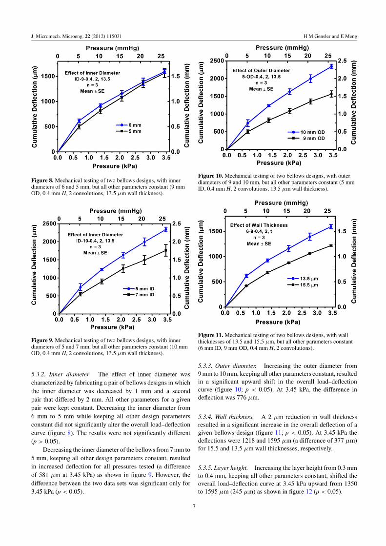
Figure 8. Mechanical testing of two bellows designs, with innerdiameters of 6 and 5 mm, but all other parameters constant (9 mmOD, 0.4 mm H, 2 convolutions, 13.5 µm wall thickness).
Figure 9. Mechanical testing of two bellows designs, with innerdiameters of 5 and 7 mm, but all other parameters constant (10 mmOD, 0.4 mm H, 2 convolutions, 13.5 µm wall thickness).
5.3.2. Inner diameter. The effect of inner diameter wascharacterized by fabricating a pair of bellows designs in whichthe inner diameter was decreased by 1 mm and a secondpair that differed by 2 mm. All other parameters for a givenpair were kept constant. Decreasing the inner diameter from6 mm to 5 mm while keeping all other design parametersconstant did not significantly alter the overall load–deflectioncurve (figure 8). The results were not significantly different(p > 0.05).
Decreasing the inner diameter of the bellows from 7 mm to5 mm, keeping all other design parameters constant, resultedin increased deflection for all pressures tested (a differenceof 581 µm at 3.45 kPa) as shown in figure 9. However, thedifference between the two data sets was significant only for3.45 kPa (p < 0.05).
Figure 10. Mechanical testing of two bellows designs, with outerdiameters of 9 and 10 mm, but all other parameters constant (5 mmID, 0.4 mm H, 2 convolutions, 13.5 µm wall thickness).
Figure 11. Mechanical testing of two bellows designs, with wallthicknesses of 13.5 and 15.5 µm, but all other parameters constant(6 mm ID, 9 mm OD, 0.4 mm H, 2 convolutions).
5.3.3. Outer diameter. Increasing the outer diameter from9 mm to 10 mm, keeping all other parameters constant, resultedin a significant upward shift in the overall load–deflectioncurve (figure 10; p < 0.05). At 3.45 kPa, the difference indeflection was 776 µm.
5.3.4. Wall thickness. A 2 µm reduction in wall thicknessresulted in a significant increase in the overall deflection of agiven bellows design (figure 11; p < 0.05). At 3.45 kPa thedeflections were 1218 and 1595 µm (a difference of 377 µm)for 15.5 and 13.5 µm wall thicknesses, respectively.
5.3.5. Layer height. Increasing the layer height from 0.3 mmto 0.4 mm, keeping all other parameters constant, shifted theoverall load–deflection curve at 3.45 kPa upward from 1350to 1595 µm (245 µm) as shown in figure 12 (p < 0.05).
7

J. Micromech. Microeng. 22 (2012) 115031 H M Gensler and E Meng
Figure 12. Mechanical testing of two bellows designs, with layerheights of 0.3 and 0.4 mm, but all other parameters constant (6 mmID, 9 mm OD, 2 convolutions, 13.5 µm wall thickness).
Figure 13. Mechanical testing of three bellows designs with 1, 2,and 3 convolutions, but all other parameters constant (6 mm ID,9 mm OD, 0.4 mm H, 13.5 µm wall thickness).
5.3.6. Number of convolutions. Increasing the number ofconvolutions from 1 to 2 and 2 to 3 resulted in a statisticallysignificant upward shift of the load–deflection curve (figure 13;p < 0.05). The shift from 2 to 3 convolutions was noticeablygreater (1595–2941 µm at 3.45 kPa) than the shift from 1 to 2convolutions (1080–1595 µm at 3.45 kPa).
5.3.7. Summary of load–deflection testing. The effects ofvarying the bellows design parameters are summarized intable 4. Entries with a % indicate statistical significance, asobtained from a t-test. Decreasing the inner-to-outer diameter(ID/OD) ratio resulted in an increase in overall deflection,but was more effective with an increase in OD rather thana decrease in ID. The wall thickness, layer height andconvolution number were varied (individually) and resultedin statistically significant changes in deflection.
(a)
(b)
Figure 14. (a) Hysteresis of the bellows (6 mm ID, 9 mm OD,0.4 mm H, 3 convolutions, 13.5 µm wall thickness) upon unloadingwas observed after load cycling the bellows up to 4.19 kPa (0.6 psi).(b) Above 4.19 kPa, dimpling (arrows) occurred at the outer edgesof the convolutions and plastic deformation was observed.
Table 4. Summary of the effects of individual bellows designparameters on load–deflection performance.
Parameter VariationEffect on deflectionat 3.45 kPa
Outer diameter Increase %Increase5–9-0.4 versus5–10-0.4 (2 convo,13.5 µm)
1 mm (11%) 776 µm (50%)
Inner diameter Decrease Increase7–10-0.4 versus5–10-0.4 (2 convo,13.5 µm)
2 mm (29%) 581 µm (33%)
Wall thickness Decrease %Increase15.5 µm versus13.5 µm (6–9-0.4, 2convo)
2 µm (13%) 377 µm (31%)
Layer height Increase %Increase6–9-0.3 versus6–9-0.4 (2 convo,13.5 µm)
0.1 mm (33%) 245 µm (18%)
Convolution number Increase %Increase1 versus 2 convo(6–9-0.4, 13.5 µm)
1 to 2 (100%) 515 µm (48%)
Convolution number Increase %Increase2 versus 3 convo(6–9-0.4, 13.5 µm)
2 to 3 (50%) 1345 µm (84%)
%Statistical significance (p < 0.05).
5.3.8. Elastic range and burst pressure. The upper limit ofthe elastic range was determined by load cycling one of thebellows (6–9-0.4, 3, 13.5 µm) until hysteresis was observed inthe load–deflection curve (figure 14). Cycling from 0.00 kPa
8
J. Micromech. Microeng. 22 (2012) 115031 H M Gensler and E Meng
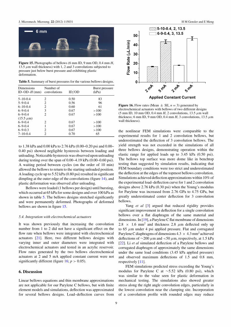
Figure 15. Photographs of bellows (6 mm ID, 9 mm OD, 0.4 mm H,13.5 µm wall thickness) with 1, 2 and 3 convolutions subjected topressure just below burst pressure and exhibiting plasticdeformation.
Table 5. Summary of burst pressures for the various bellows designs.
DimensionsID–OD–H (mm)
Number ofconvolutions ID/OD
Burst pressure(kPa)
5–10-0.4 2 0.50 835–9-0.4 2 0.56 966–10-0.4 2 0.60 616–9-0.4 3 0.67 >1006–9-0.4(15.5 µm)
2 0.67 >100
6–9-0.4 2 0.67 >1006–9-0.4 1 0.67 >1006–9-0.3 2 0.67 >1007–10-0.4 2 0.70 65
to 1.38 kPa and 0.00 kPa to 2.76 kPa (0.00–0.20 psi and 0.00–0.40 psi) showed negligible hysteresis between loading andunloading. Noticeable hysteresis was observed upon unloadingduring testing over the span of 0.00–4.19 kPa (0.00–0.60 psi).A waiting period between cycles (on the order of 10 min)allowed the bellows to return to the starting unloaded position.A loading cycle up to 5.52 kPa (0.80 psi) resulted in significantdimpling at the outer edge of the convolutions (figure 14), andplastic deformation was observed after unloading.
Bellows were loaded (1 bellows per design) until bursting,which occurred at 65 kPa for some designs and over 100 kPa asshown in table 5. The bellows designs stretched significantlyand were permanently deformed. Photographs of deformedbellows are shown in figure 15.
5.4. Integration with electrochemical actuators
It was shown previously that increasing the convolutionnumber from 1 to 2 did not have a significant effect on theflow rate when bellows were integrated with electrochemicalactuators [21]. Here, two different bellows designs withvarying inner and outer diameters were integrated withelectrochemical actuators and tested in an acrylic reservoir.Flow rates generated by the two bellows electrochemicalactuators at 2 and 5 mA applied constant current were notsignificantly different (figure 16; p > 0.05).
6. Discussion
Linear bellows equations and thin membrane approximationsare not applicable for our Parylene C bellows, but with finiteelement models and simulations, deflection was approximatedfor several bellows designs. Load–deflection curves from
Figure 16. Flow rates (Mean ± SE, n = 3) generated byelectrochemical actuators with bellows of two different designs(5 mm ID, 10 mm OD, 0.4 mm H, 2 convolutions, 13.5 µm wallthickness; 6 mm ID, 9 mm OD, 0.4 mm H, 3 convolutions, 13.5 µmwall thickness).
the nonlinear FEM simulations were comparable to theexperimental results for 1 and 2 convolution bellows, butunderestimated the deflection of 3 convolution bellows. Theyield strength was not exceeded in the simulations of allthree bellows designs, demonstrating operation within theelastic range for applied loads up to 3.45 kPa (0.50 psi).The bellows top surface was more dome like in benchtoptesting than suggested by simulation results, indicating thatFEM boundary conditions were too strict and underestimatedthe deflection at the edges of the topmost bellows convolution.Simulations achieved deflection approximations within 10% ofthe experimental load–deflection curve for 1 and 2 convolutiondesigns above 2.76 kPa (0.30 psi) when the Young’s modulusfor Parylene was increased from 2.76 GPa to 4.75 GPa, butgreatly underestimated center deflection for 3 convolutionbellows.
Yang et al [3] argued that reduced rigidity providessignificant improvement in deflection for a single convolutionbellows over a flat diaphragm of the same material anddimensions. In [19], a Parylene C flat membrane of dimensions2.8 " 1.6 mm2 and thickness 2.8 µm deflected only upto 65 µm under 4 psi applied pressure. Flat and corrugatedParylene C diaphragms of dimensions 4.3 " 4.3 mm2 achieveddeflections of !200 µm and <50 µm, respectively, at 1.5 kPa[22]. Li et al simulated deflection of a Parylene bellows andcorrugated diaphragm of approximately the same dimensionsunder the same load conditions (3.45 kPa applied pressure)and observed maximum deflections of 1.5 and 0.8 mm,respectively [11].
FEM simulations predicted stress exceeding the Young’smodulus for Parylene C at !5.52 kPa (0.80 psi), whichwas similar to the value seen for plastic deformation inmechanical testing. The simulations also showed greaterstress along the right angle convolution edges, particularly inthe lowest convolution near the clamping site. Incorporationof a convolution profile with rounded edges may reduce
9

J. Micromech. Microeng. 22 (2012) 115031 H M Gensler and E Meng
stress concentration at these locations. Sites of high stressconcentration identified by FEM simulation were highlycorrelated to sites of burst failure of fabricated bellows.
The fabrication process was relatively quick and usedminimal resources. A large number of molds can be made forthe initial fabrication steps, but the overall throughput of theprocess is limited by the manual stacking step. Automationor an improved method for stacking the PEG modulescould further increase the fabrication process throughput.The sidewall profiles of this simple hole punching methodare restricted to the smoothness obtained from the polishedmetal punches, and could be a factor in material performance.Improved mold forming technologies need to be explored forfurther improvement in mold surface quality.
Smaller ID/OD ratios and larger convolution depths(difference between outer and inner radius) may allow forgreater achievable deflection of bellows on this size scale,particularly at higher pressures. Although a power analysiswith our t-test parameters indicated that the studies wererelatively low power, we were still able to detect significancein all but one design parameter, ID. Small changes in ID from1 to 2 mm did not have a noticeable effect except at the highestpressure tested for the 2 mm case (3.45 kPa). In the case of5–9-0.4 versus 6–9-0.4, the ID to OD ratio increases from 0.56to 0.67 and in 5–10-0.4 versus 7–10-0.4, the increase is from0.50 to 0.70. This suggests that larger ID or ID to OD ratiochanges or possibly sample sizes are required to elucidate theeffect on achievable deflection. We expected that increasingOD while keeping all other parameters constant would enhancemobility and allow for greater deflection of the bellows. Thiswas confirmed in the load–deflection testing for the magnitudeof dimension change tested and the difference between the twobellows designs (varying only OD) was statistically significant.Reducing layer height (H), and thus overall bellows height,produced a statistically significant difference in deflection forthe dimension change tested, but the deflection change wasrelatively small compared to the reduction in H and wouldneed to be evaluated in the context of a given application.The number of convolutions (N) were varied to evaluatethe potential benefit of additional convolutions to increasepotential deflection range, but was kept low to minimizethe overall bellows height in consideration of minimizingdimensions for integration in low profile MEMS devices. Forthe design parameters evaluated in this work, the most effectiveway to increase bellows deflection was to increase outerdiameter, increase the number of convolutions or decreasewall thickness (table 4). Modifying these parameters providedthe greatest change in deflection while requiring relativelysmall changes in initial bellows volume under no load. Thus,there are several options for addressing the balance betweenmechanical strength and anticipated displacement volumerequirements with the overall volume occupied by the bellowsonce integrated with a MEMS actuator or system.
The load–deflection curves showed hysteresis at lowerapplied pressure loads than that with Parylene flat membranestested by Shih et al where !28 kPa (!4 psi) was the onsetof hysteresis. Time for mechanical relaxation between cycles(after dropping from 0.69 kPa to 0.00) was on the order of
10 to 20 min, which is in agreement with stress relaxationtime constants reported in [23]. Dimpling was observedat approximately the onset of hysteresis in the loading–unloading cycle. This was likely due to compressive stressesthat developed near the edge of the convolutions, as is seen insimply supported diaphragms [16].
Burst pressure testing indicated that the designs withlarger convolution depths (table 5) tended to burst at lowerloads, corresponding with the relatively larger deflection andhigher associated stress. The pressure transducer’s range waslimited to (!100 kPa) which in turn limited investigationof some parameters (such as wall thickness) on mechanicalstrength. In addition, only one bellows was used for eachdestructive test so further studies with larger sample sizesand a transducer with greater range would be needed toevaluate the effects of design parameter changes with statisticalsignificance.
Two different bellows designs integrated with electro-chemical actuators showed a statistically insignificant differ-ence in generated flow rate. It is important to note that thepressure testing and the flow rate testing setups were in differ-ent fluidic environments (air versus liquid), which may havecontributed to the insignificant effect of the tested design pa-rameter variations (number of convolutions, diameter) on flowrate. For pressure testing, bellows were clamped in an opentest fixture and deflected in ambient air. Static pressure wasapplied at the previously described values. During flow ratetesting pressure was continuously increasing via electrolysiswithin the bellows, resulting in dynamic pressure values. Thebellows deflected against fluid (water) in the rigid reservoirand the coupled fluid column in the rigid cannula, which wasopen at one end. Further investigation of bellows design pa-rameters and their effect on flow rate is warranted and will beexamined in future work. An individual bellows electrochem-ical actuator was tested over 100 times (much greater thanthat required by our intended applications) without noticeablechanges in performance when operated in the elastic range (upto 3.45 kPa). Large deflection was achieved under relativelylow applied pressures (!kPa) compared with a bellows inte-grated with a thermopneumatic actuator [3] while consumingsignificantly less power (!mm with !3 mW versus !µm with!720 mW).
7. Conclusion
We demonstrated a rapid, high-yield fabrication process forMEMS Parylene C bellows for large deflection applications.The fabricated thin film polymer bellows exhibited repeatablebehavior under loading within the determined elastic range andbellows of same design demonstrated uniform load–deflectionperformance. FEM simulations provided approximations ofload–deflection curves for several bellows designs. The onsetof hysteresis for the Parylene C bellows structure (4.19 kPaor 0.60 psi) was determined in mechanical testing. Largedeflection (!mm) was achieved under relatively low appliedpressure (!kPa). Bellows design parameters were evaluatedand it was found that convolution number, wall thickness andouter diameter had the greatest effect on load–deflection (axial
10

J. Micromech. Microeng. 22 (2012) 115031 H M Gensler and E Meng
extension) performance for the bellows designs fabricated.Bellows were combined with interdigitated electrodes to formelectrochemical actuators and fluid pumping under low power(!3 mW) was demonstrated. Several design parameters canbe adjusted to achieve a desired magnitude of deflection whilemaintaining dimensions appropriate for incorporation withMEMS actuators and devices. The bellows offer completeseparation of the electrolyte from the reservoir fluid whenintegrated with electrochemical actuators and could haveapplications in other actuators where a separation of theactuation fluids and mechanisms from other system chambersis necessary. When constructed with Parylene C, which boastsbiocompatibility, inertness to a broad range of chemicals, andlow permeability, bellows are poised to become an enablingtechnology for novel applications in MEMS actuators andmicrofluidic systems.
Acknowledgments
This work was funded in part by a National Science FoundationGraduate Research Fellowship under grant no DGE-0937362(HG) and the Wallace H Coulter Foundation Early CareerTranslational Research Award. The authors would like tothank Ms Roya Sheybani for supplying Nafion R!-coatedelectrochemical actuators and Ms Diya Dwarakanath, MsHeather Chen and Mr Jason Hoffman for their assistancewith fabrication of bellows. The authors would also like toacknowledge Dr Donghai Zhu and members of the BiomedicalMicrosystems Laboratory for their assistance with this project.
References
[1] Wilson J F 1984 Mechanics of bellows: a critical survey Int. J.Mech. Sci. 26 593–605
[2] Di Giovanni M 1982 Flat and Corrugated Diaphragm DesignHandbook (New York: Dekker)
[3] Yang X, Tai Y-C and Ho C-M 1997 Micro bellow actuatorsProc. IEEE Int. Conf. TRANSDUCERS (Beijing)pp 45–8
[4] Minami K, Morishita H and Esashi M 1999 A bellows-shapeelectrostatic microactuator Sensors Actuators A72 269–76
[5] Bonanomi G, Rebello K, Lebouitz K, Riviere C, Di Martino E,Vorp D and Zenati M A 2003 Microelectromechanicalsystems for endoscopic cardiac surgery J. Thorac.Cardiovasc. Surg. 126 851–2
[6] Feng G-H and Kim E S 2003 Universal concept for fabricatingmicron to millimeter sized 3-D parylene structures on rigidand flexible substrates Proc. IEEE Int. Conf.Microelectromechanical Systems (MEMS) (Kyoto, Japan)pp 594–7
[7] Luharuka R, Wu C-F and Hesketh P J 2004 Design,fabrication, and testing of a near constant pressure fuel
delivery system for miniature fuel cells Sensors Actuators A112 187–95
[8] Liu H-Y, Pi X-T, Zhou C-W, Zheng X-L, Hou W-Sand Wen Z-Y 2008 Design of site specific delivery capsulebased on MEMS Proc. IEEE Int. Conf. Nano/MicroEngineered and Molecular Systems (NEMS) (Sanya,Hainan Island) pp 498–501
[9] Takashima K, Noritsugu T, Rossiter J, Guo S and Mukai T2011 Development of curved type pneumatic artificialrubber muscle using shape-memory polymer Proc. SICEAnnual Conf. on Instrumentation, Control, InformationTechnology and System Integration (Tokyo, Japan)pp 1691–5
[10] Shapiro Y, Wolf A and Gabor K 2011 Bi-bellows: pneumaticbending actuator Sensors Actuators A 167 484–94
[11] Li P-Y, Sheybani R, Gutierrez C, Kuo J T W and Meng E2010 A Parylene bellows electrochemical actuatorJ. Microelectromech. Syst. 19 215–28
[12] Gensler H, Sheybani R, Li P-Y, Mann R L and Meng E 2012An implantable MEMS micropump system for drugdelivery in small animals Biomed. Microdevices14 483–96
[13] Matsui S 2003 Three-dimensional nanostructure fabrication byfocused-Ion-beam chemical vapor deposition Proc. IEEEInt. Conf. TRANSDUCERS (Boston, USA)pp 179–81
[14] Gensler H et al 2010 Implantable MEMS drug delivery devicefor cancer radiation reduction Proc. IEEE Int. Conf.Microelectromechanical Systems (MEMS) (Hong Kong,SAR, China) pp 23–6
[15] Gensler H, Sheybani R and Meng E 2011 Rapidnon-lithography based fabrication process andcharacterization of Parylene C bellows for applications inMEMS electrochemical actuators Proc. IEEE Int. Conf.TRANSDUCERS (Beijing, China) pp 2347–50
[16] Ugural A C 2009 Stresses in Beams, Plates, and Shells (BocaRaton, FL: CRC Press)
[17] Metz P, Alici G and Spinks G M 2006 A finite element modelfor bending behaviour of conducting polymerelectromechanical actuators Sensors Actuators A130–131 1–11
[18] Kim K H, Yoon H J, Jeong O C and Yang S S 2005Fabrication and test of a micro electromagnetic actuatorSensors Actuators A 117 8–16
[19] Shih C Y, Harder T A and Tai Y-C 2004 Yield strength ofthin-film parylene-C Microsyst. Technol. 10 407–11
[20] Sheybani R and Meng E 2012 High efficiency MEMSelectrochemical actuators and electrochemical impedancespectroscopy characterization J. Microelectromech. Syst.2 1197–208
[21] Sheybani R, Gensler H and Meng E 2011 Rapid and repeatedbolus drug delivery enabled by high efficiencyelectrochemical bellows actuators Proc. IEEE Int. Conf.TRANSDUCERS (Beijing, China: IEEE) pp 490–3
[22] Sim W, Kim B, Choi B and Park J-O 2005 Theoretical andexperimental studies on the parylene diaphragms formicrodevices Microsyst. Technol. 11 11–15
[23] Lin J C-H, Lam G and Tai Y-C 2012 Viscoplasticity ofparylene-C film at body temperature Proc. IEEE Int. Conf.Microelectromechanical Systems (MEMS) (Paris, France:IEEE) pp 476–9
11